EP3198246B1 - Procédé de détermination d'un état dans un véhicule ferroviaire - Google Patents
Procédé de détermination d'un état dans un véhicule ferroviaire Download PDFInfo
- Publication number
- EP3198246B1 EP3198246B1 EP15767471.4A EP15767471A EP3198246B1 EP 3198246 B1 EP3198246 B1 EP 3198246B1 EP 15767471 A EP15767471 A EP 15767471A EP 3198246 B1 EP3198246 B1 EP 3198246B1
- Authority
- EP
- European Patent Office
- Prior art keywords
- vehicle
- capturing
- end device
- mobile end
- signal
- Prior art date
- Legal status (The legal status is an assumption and is not a legal conclusion. Google has not performed a legal analysis and makes no representation as to the accuracy of the status listed.)
- Active
Links
Images
Classifications
-
- B—PERFORMING OPERATIONS; TRANSPORTING
- B61—RAILWAYS
- B61L—GUIDING RAILWAY TRAFFIC; ENSURING THE SAFETY OF RAILWAY TRAFFIC
- B61L15/00—Indicators provided on the vehicle or train for signalling purposes
- B61L15/0094—Recorders on the vehicle
-
- B—PERFORMING OPERATIONS; TRANSPORTING
- B61—RAILWAYS
- B61K—AUXILIARY EQUIPMENT SPECIALLY ADAPTED FOR RAILWAYS, NOT OTHERWISE PROVIDED FOR
- B61K9/00—Railway vehicle profile gauges; Detecting or indicating overheating of components; Apparatus on locomotives or cars to indicate bad track sections; General design of track recording vehicles
- B61K9/08—Measuring installations for surveying permanent way
-
- G—PHYSICS
- G01—MEASURING; TESTING
- G01H—MEASUREMENT OF MECHANICAL VIBRATIONS OR ULTRASONIC, SONIC OR INFRASONIC WAVES
- G01H1/00—Measuring characteristics of vibrations in solids by using direct conduction to the detector
-
- G—PHYSICS
- G01—MEASURING; TESTING
- G01M—TESTING STATIC OR DYNAMIC BALANCE OF MACHINES OR STRUCTURES; TESTING OF STRUCTURES OR APPARATUS, NOT OTHERWISE PROVIDED FOR
- G01M17/00—Testing of vehicles
- G01M17/08—Railway vehicles
-
- G—PHYSICS
- G01—MEASURING; TESTING
- G01H—MEASUREMENT OF MECHANICAL VIBRATIONS OR ULTRASONIC, SONIC OR INFRASONIC WAVES
- G01H3/00—Measuring characteristics of vibrations by using a detector in a fluid
-
- H—ELECTRICITY
- H04—ELECTRIC COMMUNICATION TECHNIQUE
- H04W—WIRELESS COMMUNICATION NETWORKS
- H04W88/00—Devices specially adapted for wireless communication networks, e.g. terminals, base stations or access point devices
- H04W88/02—Terminal devices
Definitions
- the present invention relates to a method for determining a value of at least one state parameter of a rail vehicle and/or a route of a rail vehicle, in which in at least one detection step at least one current first detection signal correlated with the current value of the state parameter is detected via a first signal sensor on a structure inside the rail vehicle, wherein a first signal sensor of a mobile terminal is used to detect the current first detection signal.
- the invention further relates to a corresponding arrangement and a corresponding mobile terminal for determining a value of such a state parameter.
- rail vehicles typically require damage or certain wear and tear on vehicle components to be identified as early as possible and appropriate measures to be taken to avert dangers for passengers or the vehicle's surroundings.
- modern rail vehicles are often equipped with appropriate proprietary sensor units that record signals on the vehicle from which the current value of certain condition parameters of the vehicle can be derived, which in turn are characteristic of a certain condition of the vehicle (typically a certain condition of one or more components of the vehicle).
- certain vibration patterns in the vehicle structure can typically be used to draw conclusions about the type of damage, and possibly even the degree of damage, to certain moving or driven components of the vehicle.
- certain vibration patterns on the vehicle can indicate certain damage to an engine rotor, the transmission, the shafts and/or wheels, etc. of the vehicle.
- the JP 2008-81102 A discloses a measuring system for a rail vehicle, which is made up of several separate components, namely acceleration sensors, a sound sensor, a GPS receiver and an A/D converter card. These components are housed in separate units and connected via corresponding signal lines to a notebook, which handles the processing of the recorded and preprocessed signals from the measuring sensors; the vibration signals are processed in a frequency range above 1 Hz.
- the present invention is therefore based on the object of providing a method, an arrangement and a mobile terminal of the type mentioned at the outset, which does not entail the above-mentioned problems or at least entails them to a lesser extent and in particular enables a simple, reliable and cost-effective determination of current values of corresponding condition parameters of the rail vehicle or the track traveled on, from which conclusions can be drawn about the current state of wear or damage of the vehicle or track.
- the present invention solves this problem on the basis of a method according to the preamble of claim 1 by the features specified in the characterizing part of claim 1. It further solves this problem on the basis of an arrangement according to the preamble of claim 13 by the features specified in the characterizing part of Claim 13. It further solves this problem starting from a mobile terminal according to the preamble of claim 16 by the features specified in the characterizing part of claim 16.
- the present invention is based on the technical teaching that it is possible to easily and reliably determine current values of corresponding condition parameters of the rail vehicle or the track traveled on, from from which conclusions can be drawn about the current state of wear or damage of the vehicle or track if higher frequency ranges of a detection signal, but in particular several different detection signals, are analyzed to determine the value of at least one state parameter. It has been shown that the internal sensors of such mobile devices generate signals with sufficient frequency resolution, which enables evaluation in higher frequency ranges above 2 Hz, preferably above 4 Hz. It is precisely in these higher frequency ranges that the system responses of the vehicle (such as the mechanical and/or acoustic vibrations) lie, which are relevant for the analysis of the state of wear or damage of the vehicle or track. It is understood that different frequency ranges can be considered or analyzed depending on the component of the vehicle of interest, depending on the aspect of the track of interest, depending on the vibration excitation of interest, or depending on the type of signal sensor used.
- the respective rotation frequency of the vibration-exciting component(s) and, if applicable, its harmonics can typically be examined.
- the respective usable frequency range of the signal pickup used also plays a role in the analysis.
- frequency ranges from 1 Hz to 10 Hz, preferably from 1 Hz to 4 Hz, more preferably from 1 Hz to 2 Hz, are typically preferably examined in the vibration analysis of suspension components of the chassis.
- frequency ranges above 2 Hz to 50 Hz, preferably from 4 Hz to 40 Hz, more preferably from 5 Hz to 30 Hz are typically preferably examined.
- frequency ranges from 10 Hz to 20 kHz, preferably from 50 Hz to 10 kHz, more preferably from 100 Hz to 1 kHz are typically preferably examined.
- such mobile devices usually allow the simultaneous recording of several different signals (such as acceleration signals, yaw rate signals, acoustic signals, etc.), the combined evaluation of which enables enables a more reliable assessment of the state of wear or damage to the vehicle or roadway.
- signals such as acceleration signals, yaw rate signals, acoustic signals, etc.
- the signal pickup in variants not according to the invention does not necessarily have to be an internal sensor of the mobile terminal. Rather, it can also be an external sensor that is (temporarily or permanently) connected to the mobile terminal (wired and/or wireless) in order to generate the relevant detection signal.
- the invention therefore relates to a method for determining a value of at least one state parameter of a rail vehicle and/or a route of a rail vehicle, in which in at least one detection step at least one current first detection signal correlated with the current value of the state parameter is detected via a first signal sensor on a structure inside the rail vehicle, wherein a first signal sensor of a mobile terminal is used to detect the current first detection signal.
- any mobile device that has at least one suitable signal pickup of this kind can be used as a mobile device.
- a mobile phone in particular a smartphone, or a tablet computer or a mobile navigation device or a smart watch is preferably used as the mobile device. This allows particularly cost-effective solutions to be achieved.
- any signal pickup can be used whose signal, with a sufficiently high frequency resolution, allows conclusions to be drawn about the current state of wear or damage of the vehicle or roadway.
- Particularly simple solutions with meaningful results regarding the current state of wear or damage can be achieved if, according to the invention, at least one acceleration sensor of the mobile terminal is used as the signal pickup and at least one yaw rate sensor of the mobile terminal and at least one microphone of the mobile terminal are used.
- at least one camera of the mobile terminal and/or at least one temperature sensor of the mobile terminal and/or at least one magnetic field sensor of the mobile terminal can be used.
- it can also be an external sensor. which is connected (temporarily or permanently) to the mobile terminal (wired and/or wireless) in order to generate the detection signal in question.
- any structure inside the vehicle is suitable as the structure inside the vehicle from which the corresponding signal is tapped or recorded, as long as the signal-technical coupling (and therefore the transfer function) between the structure and the vehicle component or the route of interest (for the condition analysis) is known to a sufficient extent.
- the structure inside the vehicle is a storage device, in particular a luggage rack and/or a table and/or a seat rack and/or a compartment of the vehicle, in particular a lockable one, wherein the mobile terminal is then connected to the storage device for the detection step, in particular placed on the storage device.
- the structure inside the vehicle can be a wall device, in particular a side wall, wherein the mobile terminal is then connected to the wall device for the detection step.
- the mobile terminal for the detection step can be firmly, in particular essentially rigidly, connected to the structure inside the vehicle, thereby ensuring in particular a sufficiently defined signal transmission or transmission function between the structure and the mobile terminal. Additionally or alternatively, the mobile terminal for the detection step can be connected to the structure inside the vehicle by means of a clamping device, in particular to ensure in particular a sufficiently defined signal transmission or transmission function between the structure and the mobile terminal.
- the mobile terminal can be connected to the structure inside the vehicle by means of a holder for the detection step.
- the holder can be arranged at any suitable location in the vehicle. For example, it can be arranged in the area of a table or a seat in the vehicle.
- the holder can be arranged in a compartment in the vehicle, with the compartment preferably being designed to be lockable. It is particularly advantageous if the holder is spatially assigned to a charging device for the power supply of the terminal. It is of course particularly convenient and therefore advantageous if it is a (for example inductive) charging device which, if necessary, enables the battery of the terminal to be charged wirelessly.
- the mobile terminal can always be connected to the structure inside the vehicle in the same measuring position and/or measuring orientation.
- the mobile terminal is connected to the structure inside the vehicle in a predeterminable first measuring position and/or measuring orientation for a first detection step when a predeterminable section of the route is driven through for the first time, while the mobile terminal is connected to the structure inside the vehicle in a predeterminable second measuring position and/or measuring orientation for a second detection step when the predeterminable section of the route is driven through for the second time.
- the value of the at least one state parameter is determined in a determination step using the current first detection signal from at least one previous detection step.
- the value of the at least one state parameter can be determined in particular using the current first detection signals from a plurality of previous detection steps. This makes it easy to take the history of the detection signals, and therefore also the state of wear or damage of the unit of interest, into account in the analysis.
- the comparison state can be recorded in any way, in particular mathematically and/or via corresponding comparison measurements on the vehicle itself or a comparison vehicle.
- the value of the at least one state parameter is determined in the determination step using at least one comparison detection signal from at least one previous comparison detection step.
- the value of the at least one state parameter can be determined in the determination step in particular using the current first detection signals from a plurality of previous detection steps and a plurality of comparison detection signals from a plurality of previous comparison detection steps.
- the at least one comparison detection step was carried out on the vehicle itself or on a comparison vehicle which corresponds to the vehicle at least in terms of the vehicle type. Additionally or alternatively, it can be provided that the at least one comparison detection step was carried out on the vehicle itself in a known state, in particular in a new state or a serviced state, in which a defined value of the at least one state parameter is given.
- the value of the at least one state parameter can be determined in the determination step using at least one comparison model value, which in turn was determined from a comparison model of the vehicle. It can be provided that the comparison model in particular supplies at least one expected value of the first detection signal at the time of detection of the at least one current first detection signal.
- At least one detection step at least one current second detection signal correlated with the current value of the at least one state parameter is detected via a second signal sensor on the rail vehicle and in the determination step, the value of the at least one state parameter is determined using the current first detection signal and the current second detection signal is determined from at least one preceding detection step, in particular from a plurality of preceding detection steps.
- a second signal sensor of the mobile terminal is used to detect the current second detection signal.
- a frequency range of the current second detection signal above 4 Hz to 15 kHz, preferably from 10 Hz to 1 kHz can be evaluated in order to also take the meaningful frequency ranges into account.
- first and second detection signals different frequencies or frequency ranges can be used for the first and second detection signals, in particular depending on the frequency range in which the wear or damage affects the respective detection signal.
- essentially the same frequency range of the current first and second detection signals can also be evaluated to determine the value of the at least one state parameter.
- any combination of detection signals can be analyzed. However, particularly meaningful results are obtained if at least one acceleration sensor and/or at least one rotation rate sensor of the mobile terminal is used as the first signal sensor and at least one microphone of the mobile terminal is used as the second signal sensor. It is precisely this combined observation of mechanical and acoustic vibrations that enables reliable conclusions to be drawn about the current state of wear or damage.
- the analyzed state parameter can in principle be any state parameter that allows suitable conclusions to be drawn about the state of wear or damage of the unit of interest. Any units can also be the subject of the analysis.
- the value of the at least one state parameter is therefore preferably representative of a state, in particular a state of wear and/or an integrity state of at least one vehicle component of the vehicle, wherein the vehicle component can in particular be a component of a chassis of the vehicle and/or a component of a drive device of the vehicle and/or a component of an auxiliary operating device of the vehicle, in particular an air conditioning system and/or a compressor of the vehicle.
- the first detection signal can be stored linked to a time identifier representative of the time of its detection and/or to a position identifier representative of the current position of the vehicle and/or the terminal and/or to at least one operating information representative of the current operating state of the vehicle, in particular a current driving speed of the vehicle, and/or to an identifier of the vehicle, in particular a unique and unambiguous identifier of the vehicle, and/or to measurement position information representative of the position of the terminal within the vehicle during the detection step.
- This advantageously makes it possible to incorporate the corresponding time information or position information or operating state information or vehicle identification or measurement position information into the analysis. This is particularly helpful in cases in which several chronologically successive series of measurements are analyzed.
- vehicle identification allows a quick assignment of the detection signal to the respective vehicle, while the measurement position information allows conclusions to be drawn about the signal transmission or transmission function between the structure and the mobile device and thus enables a more precise analysis overall.
- the value of the at least one state parameter can therefore be determined in the determination step using the position identifier and route information representative of the state of the route traveled. This has the advantage that the proportion or contribution of the route to the detected signal response of the vehicle can be estimated or taken into account using the route information.
- the at least one state parameter can be a state parameter of the vehicle, wherein the value of the at least one state parameter is determined in the determination step using the position identifier and first detection signals from a plurality of passes of the vehicle over a predeterminable section of the route. This allows the actual state of wear or damage to be determined with greater reliability based on the change in the detected signal response of the vehicle between the passes of the vehicle.
- the at least one state parameter can be a state parameter of the route, wherein the value of the at least one state parameter is then determined in the determination step using the position identifier and is determined from first detection signals from a plurality of vehicle crossings over a predeterminable section of the route and/or from crossings by a plurality of different vehicles over a predeterminable section of the route.
- the first detection signal can in principle be stored in any suitable manner and forwarded for further processing.
- the first detection signal is stored and/or forwarded in a manner that is protected against manipulation, in particular in a manner that is protected against undetected manipulation. Any suitable cryptographic methods or mechanisms can be used for this purpose.
- the first detection signal can be encrypted and/or provided with a digital signature. The same naturally applies to data that has already been prepared accordingly and is generated from the first detection signal. Such logical protection of the recorded and/or further processed data is particularly advantageous with regard to a reliable and tamper-proof analysis of the vehicle and/or the route.
- the vehicle identifier and/or the measurement position information is preferably entered into the terminal device in a recognition step via a corresponding input device.
- a corresponding input device This can be a simple input via a keyboard on the terminal device.
- the input is made via a wireless communication device and/or a barcode scanner on the terminal device.
- the input can be made by the user of the terminal device, who initiates the reading of the vehicle identification and/or the measurement position information by actuating the terminal device accordingly.
- the user of the terminal device can enter a machine-readable code attached to the vehicle (for example a barcode or the like) via a corresponding reading device (for example a barcode scanner) of the terminal device.
- a corresponding reading device for example a barcode scanner
- NFC near field communication
- Such electronic reading can in particular take place automatically, for example when entering the vehicle and/or when connecting the terminal device to a holder in the vehicle.
- the analysis of the recorded data can in principle take place anywhere.
- the determination step can be carried out in a data processing unit of the mobile terminal and/or the vehicle and/or a remote data center. Additionally or alternatively, the detection signals of the mobile terminal recorded in the at least one detection step and/or evaluation data derived therefrom for carrying out the determination step can be transmitted as transmission data to a data processing unit of the vehicle and/or a remote data center in a transmission step via a communication device of the mobile terminal, in particular via a wireless communication network.
- the above-mentioned incentive system for end device users can be implemented. It can be provided that, depending on the successful verification of the transmission data (in particular depending on its authenticity and/or usability for analysis), a remuneration for the transmission of the transmission data is made in a remuneration step following the transmission step.
- the user of the transmitting end device can receive a credit to their account (for example their bank account or a bonus points account with the vehicle operator or with a third party) as remuneration for the transmission of the transmission data. The user can then use this credit, for example, to purchase tickets from the vehicle operator, etc.
- the transmission data is logically secured (in the manner already described above) and also includes a corresponding (preferably one-time and unambiguous) identification of the terminal device and/or the user of the terminal device.
- Linking the recorded data for evaluation with a sufficiently precise identification of the terminal device can of course be advantageous in any of the above-mentioned variants. This allows conclusions to be drawn about the properties of the relevant signal sensor of the terminal device, which can then be taken into account in the evaluation. This does not necessarily have to be a clear and unique identification of the terminal device; rather, a type number of the terminal device or something similar can be sufficient to draw sufficient conclusions about the relevant signal sensor.
- a reaction can take place in a reaction step depending on the value of the at least one state parameter that was determined in the determination step.
- This can be any reaction, for example a corresponding indication to the driver or, depending on the importance of the detected state for the safety of the passengers or the vehicle environment, also an immediate, possibly automatic intervention in the operation of the vehicle (for example slowing down or completely braking the vehicle to a standstill, etc.).
- the present invention further relates to an arrangement for determining a value of at least one state parameter of a rail vehicle and/or a route of a rail vehicle, which is particularly suitable for carrying out the method according to the invention, according to claim 13.
- the present invention further relates to a mobile terminal, in particular a mobile phone, which is particularly suitable for carrying out the method according to the invention, according to claim 16.
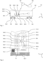
- the vehicle 101 comprises a car body 102, which is supported in the region of its two ends in a conventional manner on a chassis unit in the form of a bogie 103 with two wheel units in the form of a first wheel set 104.1 and a second wheel set 104.2. It is understood, however, that the present invention can also be used in connection with other configurations in which the car body is only supported directly on a chassis. Likewise, other wheel units, such as wheel pairs or even individual wheels, can also be provided instead of wheel sets.
- a vehicle coordinate system x, y, z (defined by the wheel contact plane of the bogie 103) is shown in the figures, in which the x-coordinate designates the vehicle longitudinal direction, the y-coordinate designates the vehicle transverse direction and the z-coordinate designates the vehicle height direction of the rail vehicle 101.
- the vehicle 101 is a vehicle for transporting people, wherein in the interior of the car body 102 there are provided seating (not shown in detail) and, in some places, tables 105.1 for the passengers, which are (essentially rigidly) attached both to the wall structure 102.1 and to the floor structure 102.2 of the car body 102.
- a mobile terminal in the form of a smartphone 106 is used to determine the current state of wear or damage of certain components of the vehicle 101 and the route T traveled, which is placed on the table 105.1 and, if necessary, fastened to the table via a holder or clamping device in the form of a clamp 110.
- the mobile terminal 106 has a series of signal sensors, in particular a first signal sensor in the form of an acceleration sensor 106.1, a second A signal pickup in the form of a microphone 106.2 and a third signal pickup in the form of a rotation rate sensor 106.3 are provided.
- the acceleration sensor 106.1 records the accelerations acting on the mobile terminal 106 in all three spatial axes or spatial directions (x, y, z) as a first detection signal S1
- the microphone 106.2 records the ambient noise as a second detection signal S2
- the rotation rate sensor 106.3 records the rotation rates around all three spatial axes (x, y, z) as a third detection signal S3.
- the mobile terminal 106 further comprises a first data processing unit in the form of a processor 106.4, which accesses a memory 106.5. Both programs and data, which the processor 106.4 uses in the operation of the mobile terminal 106, are stored in the memory 106.5.
- the mobile terminal 106 has a communication module 106.6 and a position determination device in the form of a GPS module 106.7.
- data can be exchanged with a remote second data processing unit in the form of a remote data center 108 in a conventional manner, e.g. via a wireless communication network 107.
- a connection to another data processing unit 109 of the vehicle 101 can also be made via a local wireless data connection (e.g. via a WLAN or a Bluetooth connection, etc.).
- the GPS module 106.7 is also used in a conventional manner to determine current position information of the mobile terminal 106 and to transmit it to the processor 106.4.
- the GPS module 106.7 can also be used in a conventional manner to synchronize a time recording module, such as an internal real-time clock of the processor 106.4, with an external time source. Synchronization can also be carried out via the mobile network 107.
- a measurement program is stored in the memory 106.5, during the processing of which the processor 106.4 addresses the signal sensors 106.1 to 106.3 in order to record the current values of the signals S1 to S3 via the signal sensors 106.1 to 106.3 in a first recording step and to store them as the first series of measurements MR1 in the memory 106.5.
- the values of the signals S1 to S3 are stored linked to position information PI, which is derived from the position signal of the GPS module 106.7, and linked to time information TI, which is generated in the processor 106.4.
- the detection signals S1 to S3 can also be stored linked to at least one item of operating information BI representative of the current operating state of the vehicle, in particular a current driving speed of the vehicle. Furthermore, the detection signals S1 to S3 are stored linked to a unique and unambiguous identifier VID of the vehicle 101 and to measurement position information MPI representative of the position of the terminal 106 within the vehicle 101 during the detection step. This advantageously makes it possible to also incorporate this operating information BI, vehicle identification VID and measurement position information MPI into the analysis alongside the corresponding time information TI or position information PI. This is particularly helpful in cases in which several chronologically successive measurement series MR1 to MRn are analyzed.
- the vehicle identification VID allows a quick assignment of the detection signals S1 to S3 to the respective vehicle 101, while the measurement position information MPI allows conclusions to be drawn about the signal transmission or transmission function between the structure of the vehicle 101 and the mobile terminal 106 and thus overall a more precise analysis of the detection signals S1 to S3.
- the vehicle identification or identifier VID of the vehicle 101 and the measurement position information MPI are entered or read into the terminal 106 in a recognition step.
- the reading takes place via a camera 106.9, via which the user of the terminal 106 records a barcode 112.1 that is attached to the table 105.1.
- the processor 106.4 of the terminal 106 uses a barcode scanner program stored in the memory 106.5 to extract the identifier VID of the vehicle 101 and the measurement position information MPI from the recorded barcode 112.
- the measurement position information MPI particularly indicates the exact position of the table 105.1 within the vehicle 101.
- the vehicle identification VID and the measurement position information MPI can also be carried out automatically when the terminal device 106 is attached to the table 105.1.
- the corresponding information VID, MPI can be read wirelessly via a so-called near field communication (NFC) by the communication module 106.6 from a memory 112.2 attached to the table 105.1, for example. This can be triggered by the user of the terminal device 106 or automatically, for example when the device comes sufficiently close to the memory 112.2 or by a corresponding switch (not shown) on the table 105.1.
- NFC near field communication
- the signals S1 to S3 of the first measurement series MR1 which are processed with the position identifier PI, the time identifier TI, the vehicle identification VID and the measurement position information MPI, are then transmitted as transmission data TMD via the mobile radio network 107 to the remote data center 108.
- the signals S1 to S3 of the first series of measurements MR1 which have been processed to form the transmission data TMD, are stored and forwarded by the processor 106.4 (with access to corresponding cryptographic programs in the memory 106.5) in a manner that is protected against undetected manipulation. Any suitable cryptographic methods or mechanisms can be used for this purpose.
- the processed signals S1 to S3 of the first series of measurements MR1 are linked to a unique, unique identification SID of the terminal device 106 and provided with a digital signature SIG of the terminal device 106.
- Such logical protection of the recorded and/or further processed data is particularly advantageous with regard to a reliable and tamper-proof analysis of the vehicle 101 and the route of the vehicle 101.
- the identification SID of the terminal device 106 makes it possible to draw conclusions about the location and/or properties of the signal sensors 106.1 to 106.3 installed in the terminal device 106 during the subsequent analysis of the transmission data TMD, and to incorporate this information into the analysis if necessary. It is understood that in other variants, less precise information about the terminal device 106 may also be sufficient for this purpose. For example, a type number of the terminal device may be sufficient for this purpose.
- the processed signals S1 to S3 of the first series of measurements MR1 are then analyzed in the data center 108 in order to draw conclusions about the current state of wear or damage of certain components of the vehicle 101 or the track T.
- the system responses of the vehicle 101 (such as the mechanical and/or acoustic vibrations) are located, which are relevant for the analysis of the state of wear or damage of certain components of the vehicle 101 or the track T.
- specific wear and tear conditions or damage to the individual vehicle components or the track T are typically associated with characteristic vibration patterns, which are taken into account in the analysis.
- the analysis of several signals S1 to S3 recorded simultaneously allows improved identification of the current state or a representative state parameter of the relevant component of the vehicle 101 or the track T, since specific vibration patterns of a signal (e.g. signal S1) can be associated with several different states of one or more components of the vehicle 101 or the track T, and the vibration patterns of at least one other signal recorded simultaneously (e.g. signal S2 and/or S3) enable the signal to be associated with a specific state of a component of the vehicle 101 or the track T.
- specific vibration patterns of a signal e.g. signal S1
- the vibration patterns of at least one other signal recorded simultaneously e.g. signal S2 and/or S3
- the signals S1 to S3 are evaluated in the data center 108 or the value of the at least one state parameter of the vehicle 101 or of the travel path is determined in a frequency range above 2 Hz, preferably from 4 Hz to 15 kHz, more preferably from 10 Hz to 1 kHz.
- the signals S1 and S3 are preferably examined in the frequency range above 2 Hz to 10 Hz, preferably above 2 Hz to 4 Hz, in the vibration analysis of suspension components of the chassis 103. Furthermore, for the mechanical vibration analysis of the vehicle structures, the signals S1 and S3 are each examined in a frequency range above 2 Hz to 50 Hz, preferably from 4 Hz to 40 Hz, more preferably from 5 Hz to 30 Hz. In contrast, the signal S2 is examined for the acoustic analysis in a frequency range from 10 Hz to 20 kHz, preferably from 50 Hz to 10 kHz, more preferably from 100 Hz to 1 kHz.
- the mobile terminal 106 is connected to the table 105.1 as a structure inside the vehicle 101, at which the corresponding signal S1 to S3 can be picked up or recorded.
- the structure such as the table 105.1
- the route T of interest condition analysis
- the structure inside the vehicle can be the wall device, in particular the side wall 102.1, or the floor 102.2, with the mobile terminal 106 then being connected to the wall device 102.1 or the floor 102.2 for the detection step. It is also possible to use a storage device of a seat 105.2 or to use a holder 105.3 arranged on the seat 105.2 for the mobile terminal 106.
- the storage device can also be a preferably lockable compartment 105.4 in a cabinet 105.5 connected to the vehicle structure in the vehicle 101, which then preferably has a corresponding holder for the mobile terminal 106.
- the mobile terminal 106 for the detection step can also simply be placed on the tables 105.1 if necessary.
- the mobile terminal for the detection step is firmly, in particular essentially rigidly, connected to the table 105.1 (or the relevant structure inside the vehicle 101) via the holder or clamping device 110 as described, which in particular ensures a sufficiently defined signal transmission or transmission function between the relevant structure (e.g. the table 105.1) and the mobile terminal 106.
- the holder or clamping device 110 is spatially assigned to a charging device 111 for the power supply of the terminal device. It is of course particularly convenient and therefore advantageous if it is a (for example inductive) charging device 111, which optionally also enables wireless charging of the battery 106.8 of the terminal device 106.
- a series of measurements MR1 from one recording step. This may, for example, be a series of measurements that was recorded when driving over a specific section of the route once.
- the mobile terminal 106 can basically always be connected to the structure inside the vehicle 101 (e.g. the table 105.1) in the same measurement position and/or measurement orientation.
- the mobile terminal 106 is connected to the structure inside the vehicle 101 (e.g. the table 105.1) in a predeterminable first measuring position and/or measuring orientation when a predeterminable section of the route T is first traveled through for a first detection step or a first series of measurements MR1, while the mobile terminal 106 is connected to the structure inside the vehicle 101 (e.g. the table 105.1) in a predeterminable second measuring position and/or measuring orientation when the predeterminable section of the route T is first traveled through for a second detection step or a second series of measurements MR2.
- the value of the at least one state parameter is determined using the detection signals S1 to S3 from one or more previous detection steps or one or more previous series of measurements MR2 to MRn.
- a comparison is preferably made between a sufficiently known previous state and the current state as it results from the current measurement or series of measurements MR1, since this allows reliable conclusions to be drawn in particular about the wear mechanisms or damage mechanisms underlying the change in state.
- the comparison state can in principle have been recorded in any way, in particular mathematically and/or via corresponding comparison measurements on the vehicle 101 itself or a comparison vehicle.
- the value of the at least one state parameter is determined in the determination step using comparison detection signals VS1 to VS3 from at least one previous comparison detection step or at least one previous series of measurements MR2 to MRn.
- the value of the at least one state parameter can be determined in the determination step using the current first detection signals from a plurality of previous detection steps or series of measurements MR2 to MRn and a plurality of comparison detection signals from a plurality of previous comparison detection steps VS1 to VS3.
- the at least one comparison detection step (with the comparison detection signals VS1 to VS3) was carried out via the mobile terminal 106 on the vehicle 101 itself in a known state, in particular in a new state or a maintenance state, in which a defined value of the at least one state parameter is given.
- the value of the at least one state parameter can be determined in the determination step using at least one comparison model value VM1 to VM3, which in turn was determined from a comparison model of the vehicle 101. It can be provided that the comparison model with the comparison model values VM1 to VM3 each delivers the expected value of the respective detection signal S1 to S3 at the time of detection of the current detection signal S1 to S3.
- different frequencies or frequency ranges can be used for the different detection signals S1 to S3, in particular depending on the frequency range in which the wear or damage affects the respective detection signal S1 to S3.
- essentially the same frequency range of the respective current detection signal S1 to S3 can also be evaluated to determine the value of the at least one state parameter.
- any components of the vehicle 101 can be the subject of the analysis.
- the vehicle component can be a component of a bogie 103 and/or a component of a drive device of the vehicle 101 and/or a component of an auxiliary operating device of the vehicle 101, in particular an air conditioning system and/or a compressor of the vehicle 101.
- the analysis in the determination step can also be determined using the position information and route information representative of the state of the route traveled (at the location corresponding to the position information PI). This has the advantage that the proportion or contribution of the route T to the detected signal response of the vehicle 101 can be estimated or taken into account using the route information.
- the value of the relevant state parameter of a component of the vehicle 101 can be determined in the determination step using the position identifier or position information PI and detection signals S1 to S3 from a plurality of passes of the vehicle 101 (or corresponding measurement series MR1 to MRn) over a predeterminable section of the route T. This makes it possible to draw conclusions about the actual state of wear or damage of the component of the vehicle 101 with greater reliability based on the change in the detected signal response of the vehicle 101 between the passes of the vehicle 101.
- the value of a state parameter of the route T can then be determined in the determination step using the position identifier or position information PI and detection signals S1 to S3 from a plurality of crossings of the vehicle 101 over a predeterminable section of the route and/or from crossings of a plurality of different vehicles 101 over a predeterminable section of the route T.
- the analysis of the recorded data or measurement series MR1 to MRn takes place in the remote data center 108.
- the analysis i.e. the determination step
- the analysis is additionally or alternatively carried out in the processor 106.4 of the mobile terminal 106 and/or in the data processing unit 109 of the vehicle 101.
- a reaction can take place in a reaction step depending on the result of the analysis, i.e. depending on the value of the at least one state parameter that was determined in the determination step.
- This can be any reaction, for example a corresponding indication to the driver of the vehicle 101 or, depending on the importance of the detected state for the safety of the passengers or the vehicle environment, also an immediate, possibly automatic intervention in the operation of the vehicle 101 (for example slowing down or completely braking the vehicle to a standstill, etc.).
- an incentive system for terminal users can also be implemented in an advantageous manner. It can be provided that, depending on the successful verification of the transmission data TMD (in particular depending on its authenticity and/or usability for analysis), a remuneration for the transmission of the transmission data TMD is made in a remuneration step following the transmission step.
- the user of the transmitting terminal 106 can receive a credit to his account (for example his bank account or a bonus points account with the operator of the vehicle or with a third party) as remuneration for the transmission of the transmission data TMD. The user can then use this credit, for example, to purchase tickets from the operator of the vehicle 101, etc.
- the transmission data TMD are logically secured via the digital signature SIG in the manner already described above and can also be clearly assigned to the terminal 106 and thus to the user of the terminal 106 in a tamper-proof manner via the one-time and unambiguous identification SID of the terminal 106.
- the present invention has been described above exclusively using examples in which the detection signals S1 and S3 were evaluated in all three spatial directions (x, y, z). However, it is understood that the invention can also be used in connection with detection signals in which fewer or only some of the three spatial directions (x, y, z) are evaluated, if meaningful conclusions can be drawn from this alone.
Landscapes
- Physics & Mathematics (AREA)
- General Physics & Mathematics (AREA)
- Engineering & Computer Science (AREA)
- Mechanical Engineering (AREA)
- Electric Propulsion And Braking For Vehicles (AREA)
- Time Recorders, Dirve Recorders, Access Control (AREA)
- Train Traffic Observation, Control, And Security (AREA)
- Navigation (AREA)
- Fittings On The Vehicle Exterior For Carrying Loads, And Devices For Holding Or Mounting Articles (AREA)
- Measurement Of Mechanical Vibrations Or Ultrasonic Waves (AREA)
Claims (16)
- Procédé pour déterminer une valeur d'au moins un paramètre d'état d'un véhicule ferroviaire (101) et/ou d'un itinéraire d'un véhicule ferroviaire (101), dans lequel- dans au moins une étape de prise, au moins un premier signal de détection actuel corrélé avec la valeur actuelle du paramètre d'état est pris via un premier capteur de signal (106.1, 106.2, 106.3) sur une structure à l'intérieur du véhicule ferroviaire (101), dans lequel- pour prendre le premier signal de prise actuel, un premier capteur de signal (106.1, 106.2 , 106.3) d'un terminal mobile (106) est utilisé,caractérisé en ce que- pour déterminer la valeur de l'au moins un paramètre d'état, une plage de fréquences du premier signal de prise actuel supérieure à 2 Hz est évalué, dans lequel- le premier capteur de signal (106.1, 106.2 , 106.3) est un capteur interne (106.1, 106.2 , 106.3) du terminal mobile (106), dans lequel- comme capteur de signal, au moins un capteur d'accélération (106.1) du terminal mobile (106) est utilisé
et- comme capteur de signal, au moins un capteur de vitesse de rotation (106.3) du terminal mobile (106.3). le terminal mobile (106) est utilisé
et- comme capteur de signal au moins un microphone (106.2) du terminal mobile (106) est utilisé. - Procédé selon la revendication 1, caractérisé en ce que- un téléphone mobile, en particulier un smartphone, est utilisé comme terminal mobile (106)
ou- une tablette est utilisée comme terminal mobile (106)
ou- un appareil de navigation mobile est utilisé comme terminal mobile (106)
ou- une SmartWatch est utilisée comme terminal mobile (106). - Procédé selon la revendication 1 ou 2, dans lequel- comme capteur de signal au moins une caméra du terminal mobile (106) est utilisée
et/ou- comme capteur de signal, au moins un capteur de température du terminal mobile et/ou au moins un capteur de champ magnétique du terminal mobile (106) est utilisé. - Procédé selon l'une des revendications 1 à 3, dans lequel- la structure interne du véhicule (101) est un dispositif de rangement, notamment un porte-bagages et/ou une table (105) et/ou un dépôt d'une siège (105.2), et/ou un compartiment, notamment verrouillable, du véhicule (105.4), et le terminal mobile (106) pour l'étape de prise est placé sur le dispositif de rangement (105), et/ou- la structure à l'intérieur du véhicule (101) est un dispositif de paroi (102.1. 102.2), notamment une paroi latérale (102.1), et le terminal mobile (106) pour l'étape de prise est connecté avec le dispositif mural (102.1, 102.2),
et/ou- le terminal mobile (106) pour l'étape de prise est relié de manière ferme, en particulier sensiblement rigide, à la structure à l'intérieur du véhicule (101),
et/ou- le terminal mobile (106) pour l'étape de prise est relié à la structure à l'intérieur du véhicule (101) au moyen d'un dispositif de serrage,
et/ou- le terminal mobile (106) pour l'étape de prise est relié à la structure à l'intérieur du véhicule (101) à l'aide d'un support (105.3, 110), le support notamment étant disposé dans un compartiment (105.4) du véhicule (101), le compartiment (105.4) étant notamment conçu pour être verrouillable, et/ou le support (105.3, 110) notamment étant spatialement attribué à un dispositif de chargement (11 1) pour le terminal (106),
et/ou- le terminal mobile (106) pour une première étape de prise lors d'un roulage premier sur un tronçon prédéterminé de l'itinéraire est connecté dans une première position de mesure et/ou dans une première orientation de mesure prédéterminée à la structure à l'intérieur du véhicule (101) et le terminal mobile (106) lors d'un roulage deuxième sur le tronçon prédéterminé de l'itinéraire est connecté dans une deuxième position de mesure et/ou dans une deuxième orientation de mesure prédéterminée à la structure à l'intérieur du véhicule (101). - Procédé selon l'une des revendications 1 à 4, dans lequel- dans une étape de détermination, la valeur du au moins un paramètre d'état est déterminée à l'aide du premier signal de prise actuel provenant d'au moins une étape de prise précédente, dans lequel- dans l'étape de détermination, la valeur du ou des paramètres d'état, en particulier à l'aide des premiers signaux de détection actuels, est déterminée à partir d'une pluralité d'étapes de détection précédentes.
- Procédé selon la revendication 5, dans lequel- la valeur du au moins un paramètre d'état est déterminée dans l'étape de détermination en utilisant au moins un signal de prise de comparaison provenant d'au moins une étape de prise de comparaison précédente,
dans lequel- la valeur du au moins un paramètre d'état dans l'étape de détermination utilisant notamment les premiers signaux de prise courants issus d'une pluralité d'étapes de prise précédentes et une pluralité de signaux de prise de comparaison sont déterminés à partir d'une pluralité d'étapes de prise de comparaison précédentes,
et/ou- l'au moins une étape de prise de comparaison a été réalisée notamment sur le véhicule ou a été réalisée sur un véhicule de comparaison qui correspond au véhicule au moins en termes de type de véhicule,
et/ou- l'au moins une étape de prise de comparaison a été réalisée notamment sur le véhicule dans un état connu, en particulier dans un nouvel état ou un état de maintenance, dans lequel une valeur définie de l'au moins un paramètre d'état est donnée. - Procédé selon la revendication 5 ou 6, dans lequel- la valeur du au moins un paramètre d'état est déterminée dans l'étape de détermination en utilisant au moins une valeur de modèle de comparaison qui a été déterminée à partir d'un modèle de comparaison du véhicule (101), dans lequel- le modèle de comparaison notamment donne au moins une valeur attendue du premier signal de prise au moment de la détection de l'au moins un premier signal de prise courant.
- Procédé selon l'une des revendications 1 à 7, dans lequel- dans au moins une étape de prise, au moins un deuxième signal de prise actuel corrélé à la valeur actuelle du au moins un paramètre d'état est pris via un deuxième capteur de signal (106.1, 106.2, 106.3) sur le véhicule ferroviaire et- dans l'étape de détermination, la valeur du au moins un paramètre d'état est déterminée à l'aide du premier signal de prise actuel et du deuxième signal de prise actuel provenant d'au moins une étape de prise précédente, en particulier d'une pluralité de étapes de détection précédentes,
dans lequel- pour détecter le deuxième signal de prise actuel, en particulier un deuxième capteur de signal (106.1, 106.2, 106.3) du terminal mobile (106) est utilisé,
et/ou- pour déterminer la valeur d'au moins un paramètre d'état, en particulier une plage de fréquence du deuxième signal de prise actuel au-dessus 4 Hz à 15 kHz, de préférence de 10 Hz à 1 kHz, est évaluée,
et/ou- pour déterminer la valeur d'au moins un paramètre d'état, en particulier essentiellement la même plage de fréquences du premier et du deuxième signal de prise actuels, est évalué,
et/ou- en tant que premier capteur de signal (106.1, 106.2, 106.3), en particulier au moins un capteur d'accélération et/ou au moins un capteur de vitesse de rotation, du terminal mobile (106) est utilisé et comme deuxième capteur de signal (106.1, 106.2, 106.3), en particulier au moins un microphone du terminal mobile (106) ets utilisé. - Procédé selon l'une des revendications 1 à 8, dans lequel- la valeur de l'au moins un paramètre d'état est représentative d'un état, notamment d'un état d'usure et/ou d'un état d'intégrité d'au moins un composant du véhicule (101),
dans lequel- le composant du véhicule est en particulier un composant d'un châssis du véhicule (101)et/ou- le composant du véhicule en particulier un composant d'un dispositif d'entraînement du véhicule (101)
et/ou- le composant du véhicule dans en particulier un composant d'un dispositif auxiliaire du véhicule (101), en particulier un système de climatisation et/ou un compresseur du véhicule (101). - Procédé selon l'une des revendications 1 à 9, dans lequel- le premier signal de prise est stocké de manière liée avec un identifiant temporel représentatif de l'heure de sa capture et/ou avec un identifiant de position représentatif de la position actuelle du véhicule (101) et/ou du terminal et/ou avec au moins une information de fonctionnement représentative pour l'état de fonctionnement actuel du véhicule (101), en particulier, pour une vitesse de conduite actuelle du véhicule (101), et/ou avec un identifiant du véhicule (101), notamment avec un identifiant singulaire et unique du véhicule (101), et/ou avec un identifiant de position de prise représentatif de la position actuelle du terminal dans le véhicule (101),
dans lequel- la valeur d'au moins un paramètre d'état est déterminée dans l'étape de détermination utilisant notamment l'identifiant de position et des informations d'itinéraire représentatives de l'itinéraire du véhicule conduit,
et/ou- l'au moins un paramètre d'état notamment est un paramètre d'état du véhicule (101), et la valeur de l'au moins un paramètre d'état est déterminée dans l'étape de détermination utilisant l'identifiant de position et les premiers signaux de détection provenant d'une pluralité de passages du véhicule (101) sur une section prédéterminée de l'itinéraire,
et/ou- l'au moins un paramètre d'état est notamment un paramètre d'état de l'itinéraire et la valeur de l'au moins un paramètre d'état est déterminé dans l'étape de détermination à l'aide de l'identifiant de position et de premiers signaux de prise issus d'une pluralité de traversées du véhicule (101) sur un tronçon prédéterminé de l'itinéraire et/ou à partir de traversées de plusieurs véhicules différents sur un tronçon prédéterminé de l'itinéraire,
et/ou- le premier signal de détection est stocké de manière protégée contre toute manipulation, en particulier de manière protégée contre une manipulation non détectée, en particulier est crypté et/ou est doté d'une signature digitale;
et/ou- l'identifiant du véhicule (101) et/ou l'information de position de mesure est entrée dans le terminal (106) dans une étape de reconnaissance via un dispositif de saisie, notamment un dispositif de communication sans fil et/ou un lecteur de code-barres, notamment automatiquement lors de l'entrée dans le véhicule et/ou lors de la connexion du terminal (106) à un support (105.3, 110) du véhicule (101). - Procédé selon l'une des revendications 1 à 10, dans lequel- l'étape de détermination est réalisée dans une unité de traitement de données du terminal mobile (106) et/ou du véhicule (101) et/ou d'un centre de données distant (108)
et/ou- les signaux de détection du terminal mobile (106) enregistrés lors de l'au moins une étape de prise et/ou les données d'évaluation qui en dérivent pour sont transmis, dans une étape de transmission, pour effectuer l'étape de détermination via un dispositif de communication (106.6) du terminal mobile (106), notamment via un réseau de communication sans fil (107), vers une unité de traitement de données du véhicule (101) et/ou un centre de données distant (108), dans lequel notamment dans une étape de rémunération suivant l'étape de transmission une compensation pour la transmission des données a lieu,
et/ou- dans une étape de réaction, une réaction a lieu en fonction de la valeur du ou des paramètres d'état qui ont été déterminés lors de l'étape de détermination. - Procédé selon l'une des revendications 1 à 10, dans lequel- pour déterminer la valeur de l'au moins un premier paramètre d'état, une plage de fréquence du premier signal de prise actuel au-dessus 4 Hz à 15 kHz, de préférence de 10 Hz à 1 kHz, est évaluée.
- Agencement pour déterminer une valeur d'au moins un paramètre d'état d'un véhicule ferroviaire (101) et/ou d'un itinéraire d'un véhicule ferroviaire (101), notamment pour mettre en oeuvre le procédé selon l'une des revendications 1 à 11, avec- un véhicule ferroviaire (101),- un dispositif de prise (106) et- au moins un dispositif de traitement de données (106.4, 108, 109), dans lequel- le dispositif de prise (106) est conçu pour, dans au moins une étape de prise, prendre au moins un premier signal de prise actuel corrélé à la valeur actuelle du paramètre d'état via un premier capteur de signal (106.1, 106.2, 106.3) sur le véhicule ferroviaire, et- le dispositif de traitement de données (106.4, 108, 109) est conçu pour déterminer la valeur du au moins un paramètre d'état dans une étape de détermination utilisant le premier signal de prise actuel du dispositif de détection (106) provenant d'au moins une étape de prise précédente,- le premier capteur de signal (106.1, 106.2, 106.3) est un capteur de signal (106.1, 106.2, 106.3) d'un terminal mobile (106), qui est disposé sur une structure à l'intérieur du véhicule (101) dans au moins une position de mesure et/ou dans au moins une orientation de mesure,caractérisé en ce que- le dispositif de traitement de données (106.4, 108, 109) est conçu pour déterminer la valeur du au moins un paramètre d'état, une plage de fréquence du premier signal de prise actuel supérieure à 2 Hz, dans lequel- le premier capteur de signal (106.1, 106.2 , 106.3) est un capteur interne (106.1, 106.2 , 106.3) du terminal mobile (106), dans lequel- comme capteur de signal, au moins un capteur d'accélération (106.1) du terminal mobile (106) est utilisé
et- comme capteur de signal, au moins un capteur de vitesse de rotation (106.3) du terminal mobile (106.3). le terminal mobile (106) est utilisé
et- comme capteur de signal au moins un microphone (106.2) du terminal mobile (106) est utilisé. - Agencement selon la revendication 13, dans lequel- le terminal mobile (106) est un téléphone mobile, en particulier un smartphone, ou une tablette ou un appareil de navigation mobile ou une SmartWatch,
et/ou- comme l'au moins un capteur de signal en plus au moins une caméra du terminal mobile (106) et/ou au moins un capteur de température du terminal mobile et/ou au moins un capteur de champ magnétique du terminal mobile (106) est utilisé.
et/ou- la structure interne du véhicule (101) est un dispositif de rangement, notamment un porte-bagages et/ou une table (105) et/ou un dépôt d'une siège (105.2), et/ou un compartiment, notamment verrouillable, du véhicule (105.4), et le terminal mobile (106) pour l'étape de prise est connectable au dispositif de rangement (105), notamment place sur le dispositif de rangement (105),
et/ou- la structure à l'intérieur du véhicule (101) comprend un dispositif de paroi (102.1. 102.2), notamment une paroi latérale (102.1), et le terminal mobile (106) pour l'étape de prise est connectable avec le dispositif de paroi (102.1, 102.2),
et/ou- le terminal mobile (106) pour l'étape de prise est relié de manière ferme, en particulier sensiblement rigide, à la structure à l'intérieur du véhicule (101),
et/ou- le terminal mobile (106) pour l'étape de prise est relié à la structure à l'intérieur du véhicule (101) au moyen d'un dispositif de serrage,
et/ou- un support (105.3, 110) est prévu, le terminal mobile (106) pour l'étape de prise pouvant être relié à la structure à l'intérieur du véhicule (101) à l'aide du support (105.3, 110), le support notamment étant disposé dans un compartiment (105.4) du véhicule (101), le compartiment (105.4) étant notamment conçu pour être verrouillable, et/ou le support (105.3, 110) notamment étant spatialement attribué à un dispositif de chargement (11 1) pour le terminal (106),
et/ou- un support (105.3, 110) connectable à la structure à l'intérieur du véhicule (101) est prévu, le support (105.3, 110) étant conçu pour tenir le terminal mobile (106) pour une première étape de prise lors d'un roulage premier sur un tronçon prédéterminé de l'itinéraire dans une première position de mesure et/ou dans une première orientation de mesure prédéterminée et de tenir le terminal mobile (106) lors d'un roulage deuxième sur le tronçon prédéterminé de l'itinéraire est connecté dans une deuxième position de mesure et/ou dans une deuxième orientation de mesure prédéterminée. - Agencement selon la revendication 12 ou 13, dans lequel- le au moins un dispositif de traitement de données (109) est un dispositif de traitement de données du véhicule (101)
et/ou- le au moins un dispositif de traitement de données (106.4) est un dispositif de traitement de données du terminal mobile (106). - Terminal mobile, en particulier téléphone mobile, pour déterminer une valeur d'au moins un paramètre d'état d'un véhicule ferroviaire (101) et/ou un itinéraire d'un véhicule ferroviaire (101), notamment pour mettre en oeuvre le procédé selon l'un des revendications 1 à 11, avec- au moins un premier capteur de signal (106.1, 106.2, 106.3) et- un dispositif de traitement de données (106.4), dans lequel- le au moins un premier capteur de signal (106.1, 106.2, 106.3) est conçu pour détecter au moins un premier signal de prise actuel corrélé à la valeur actuelle du paramètre d'état,caractérisé en ce que- le premier capteur de signal (106.1, 106.2 , 106.3) est un capteur interne (106.1, 106.2 , 106.3) du terminal mobile (106), dans lequel- comme capteur de signal, au moins un capteur d'accélération (106.1) du terminal mobile (106) est utilisé
et- comme capteur de signal, au moins un capteur de vitesse de rotation (106.3) du terminal mobile (106.3). le terminal mobile (106) est utilisé
et- comme capteur de signal au moins un microphone (106.2) du terminal mobile (106) est utilisé,dans lequel- le dispositif de traitement de données (106.) est conçu pour évaluer une plage de fréquences du premier signal de prise actuel supérieure à 2 Hz.
Priority Applications (1)
| Application Number | Priority Date | Filing Date | Title |
|---|---|---|---|
| EP24208018.2A EP4474781A3 (fr) | 2014-09-22 | 2015-09-22 | Procédé de détermination d'un état dans un véhicule ferroviaire |
Applications Claiming Priority (2)
| Application Number | Priority Date | Filing Date | Title |
|---|---|---|---|
| DE102014113669.1A DE102014113669A1 (de) | 2014-09-22 | 2014-09-22 | Verfahren zur Zustandsermittlung in einem Schienenfahrzeug |
| PCT/EP2015/071767 WO2016046217A1 (fr) | 2014-09-22 | 2015-09-22 | Procédé de détermination d'un état dans un véhicule ferroviaire |
Related Child Applications (1)
| Application Number | Title | Priority Date | Filing Date |
|---|---|---|---|
| EP24208018.2A Division EP4474781A3 (fr) | 2014-09-22 | 2015-09-22 | Procédé de détermination d'un état dans un véhicule ferroviaire |
Publications (2)
| Publication Number | Publication Date |
|---|---|
| EP3198246A1 EP3198246A1 (fr) | 2017-08-02 |
| EP3198246B1 true EP3198246B1 (fr) | 2024-11-20 |
Family
ID=54185955
Family Applications (2)
| Application Number | Title | Priority Date | Filing Date |
|---|---|---|---|
| EP15767471.4A Active EP3198246B1 (fr) | 2014-09-22 | 2015-09-22 | Procédé de détermination d'un état dans un véhicule ferroviaire |
| EP24208018.2A Pending EP4474781A3 (fr) | 2014-09-22 | 2015-09-22 | Procédé de détermination d'un état dans un véhicule ferroviaire |
Family Applications After (1)
| Application Number | Title | Priority Date | Filing Date |
|---|---|---|---|
| EP24208018.2A Pending EP4474781A3 (fr) | 2014-09-22 | 2015-09-22 | Procédé de détermination d'un état dans un véhicule ferroviaire |
Country Status (12)
| Country | Link |
|---|---|
| US (1) | US10343700B2 (fr) |
| EP (2) | EP3198246B1 (fr) |
| JP (1) | JP2017529544A (fr) |
| CN (2) | CN116878567A (fr) |
| AU (1) | AU2015320850B2 (fr) |
| CA (1) | CA2962116C (fr) |
| DE (1) | DE102014113669A1 (fr) |
| ES (1) | ES3001565T3 (fr) |
| PL (1) | PL3198246T3 (fr) |
| RU (1) | RU2691547C2 (fr) |
| WO (1) | WO2016046217A1 (fr) |
| ZA (1) | ZA201702823B (fr) |
Families Citing this family (19)
| Publication number | Priority date | Publication date | Assignee | Title |
|---|---|---|---|---|
| US11208129B2 (en) * | 2002-06-04 | 2021-12-28 | Transportation Ip Holdings, Llc | Vehicle control system and method |
| WO2018110553A1 (fr) * | 2016-12-16 | 2018-06-21 | 株式会社エイクラ通信 | Oscillomètre portable et programme de mesure d'oscillation |
| DE102017100444C5 (de) * | 2017-01-11 | 2020-12-03 | Dormakaba Deutschland Gmbh | Verfahren und Konfigurationssystem zum Konfigurieren eines Bewegungsablaufs einer zumindest teilautomatisierten Türanlage |
| CN110651305B (zh) * | 2017-06-22 | 2023-02-03 | 北京嘀嘀无限科技发展有限公司 | 车辆价值评估的系统和方法 |
| DE102017217300A1 (de) * | 2017-09-28 | 2019-03-28 | Siemens Mobility GmbH | Verfahren und Vorrichtung zum Ermitteln einer Streckeninformation in Bezug auf eine von einem spurgebundenen Fahrzeug befahrbare Strecke |
| CN108248616A (zh) * | 2017-12-28 | 2018-07-06 | 安徽铁总智能装备有限公司 | 一种货运动车组 |
| US12371077B2 (en) * | 2018-01-24 | 2025-07-29 | Amsted Rail Company, Inc. | Sensing method, system and assembly for railway assets |
| CA3089133C (fr) * | 2018-01-24 | 2024-07-02 | Amsted Rail Company, Inc. | Procede, systeme et ensemble de detection de trappe de dechargement |
| CN110304104B (zh) * | 2018-03-20 | 2022-01-28 | 张海龙 | 一种轨道晃动实时动态监测方法、装置及系统 |
| AU2019300171B2 (en) | 2018-07-12 | 2022-09-29 | Amsted Rail Company, Inc. | Brake monitoring systems for railcars |
| CN109327854B (zh) * | 2018-11-15 | 2022-05-31 | 中国联合网络通信集团有限公司 | 轨道用户识别方法及装置 |
| CN110542569B (zh) * | 2019-09-23 | 2024-12-10 | 天津航天瑞莱科技有限公司 | 一种可调节式行李架通用夹具 |
| EP3843421A1 (fr) | 2019-12-23 | 2021-06-30 | Bombardier Transportation GmbH | Surveillance des conditions à bord d'un véhicule |
| CN111693246B (zh) * | 2020-06-23 | 2021-04-06 | 中国空气动力研究与发展中心超高速空气动力研究所 | 连续在轨运动的主体和分离体轨迹捕获实验运动分配方法 |
| CN113155465B (zh) * | 2021-04-22 | 2022-06-21 | 上海工程技术大学 | 一种便携式地铁牵引电机轴承状态检测装置 |
| CN113624517A (zh) * | 2021-08-02 | 2021-11-09 | 李俊 | 一种基于轨道线路设备联合gps系统的振动测试方法 |
| CN114117591B (zh) * | 2021-11-12 | 2024-09-03 | 北京市科学技术研究院城市安全与环境科学研究所 | 地铁车辆段上盖建筑室内振动剂量评价方法及装置 |
| CN116046147A (zh) | 2023-02-22 | 2023-05-02 | 浙江省计量科学研究院 | 一种智能噪声传感器 |
| DE102023209589A1 (de) * | 2023-09-29 | 2025-04-03 | Zf Friedrichshafen Ag | Verfahren und System zum Bestimmen eines Zustands einer Komponente eines Zuges für ein Bestimmen eines Wartungsplans des Zuges |
Citations (13)
| Publication number | Priority date | Publication date | Assignee | Title |
|---|---|---|---|---|
| US20060219016A1 (en) | 2005-03-31 | 2006-10-05 | Li-Peng Wang | Silicon micromachined ultra-sensitive vibration spectrum sensor array (VSSA) |
| US20070208841A1 (en) * | 2006-03-01 | 2007-09-06 | L-3 Communications Corporation | Self-assembling wireless network, vehicle communications system, railroad wheel and bearing monitoring system and methods therefor |
| JP2008081102A (ja) | 2006-08-31 | 2008-04-10 | Hokkaido Railway Co | 車両走行動揺/騒音解析システム、車両走行動揺/騒音解析方法、車両走行騒音解析システムおよび車両走行騒音解析方法 |
| US20080272906A1 (en) | 2002-06-11 | 2008-11-06 | Intelligent Technologies International, Inc. | Vehicle Monitoring Using Cellular Phones |
| US20090001226A1 (en) | 2007-06-27 | 2009-01-01 | Rftrax, Inc. | Acoustic monitoring of railcar running gear and railcars |
| US20120053805A1 (en) * | 2010-08-30 | 2012-03-01 | The University Of North Texas | Methods for detection of driving conditions and habits |
| DE102012211041A1 (de) | 2012-06-27 | 2014-01-02 | Robert Bosch Gmbh | Verfahren zur Unterstützung eines Einparksystems mittels portabler Sensoren |
| EP2687818A2 (fr) | 2012-07-20 | 2014-01-22 | MAN Truck & Bus AG | Procédé et dispositif pour cartographier des états routiers |
| DE102012106807A1 (de) * | 2012-07-26 | 2014-01-30 | Continental Reifen Deutschland Gmbh | Verfahren zum Anzeigen einer Handlungsempfehlung auf einem Smartphone bei einer Beschädigung an einem Fahrzeugreifen |
| DE102012015188A1 (de) | 2012-08-02 | 2014-02-06 | Deutsches Forschungszentrum für künstliche Intelligenz GmbH | Aktiv oder passiv angetriebenes Rad mit einer Odometrie-Sensoreinheit, muskelkraft- oder motorbetriebenes Fortbewegungsmittel mit selbigem und System mit selbigem und Basisgerät |
| DE102012219111A1 (de) | 2012-10-19 | 2014-04-24 | Deutsches Zentrum für Luft- und Raumfahrt e.V. | Verfahren zur Lokalisierung eines Schienenfahrzeugs innerhalb eines Schienennetzes |
| DE102013202521A1 (de) | 2013-02-15 | 2014-08-21 | Robert Bosch Gmbh | Vorrichtung und Verfahren zum Ermitteln mindestens eines Qualitätsparameters eines Streckenabschnitts eines Verkehrsweges für ein Kleinfahrzeug |
| EP2833115A1 (fr) | 2012-03-28 | 2015-02-04 | NTN Corporation | Système de détection du mauvais fonctionnement d'un palier de véhicule ferroviaire |
Family Cites Families (14)
| Publication number | Priority date | Publication date | Assignee | Title |
|---|---|---|---|---|
| US5433111A (en) * | 1994-05-05 | 1995-07-18 | General Electric Company | Apparatus and method for detecting defective conditions in railway vehicle wheels and railtracks |
| US6570497B2 (en) * | 2001-08-30 | 2003-05-27 | General Electric Company | Apparatus and method for rail track inspection |
| KR100674475B1 (ko) * | 2006-01-12 | 2007-01-25 | 한정식 | 아크형 손톱깎이 날체의 제조방법 및 이에 의한 손톱깎이날체 및 손톱깎이 |
| US8326582B2 (en) * | 2008-12-18 | 2012-12-04 | International Electronic Machines Corporation | Acoustic-based rotating component analysis |
| GB0915322D0 (en) * | 2009-09-03 | 2009-10-07 | Westinghouse Brake & Signal | Railway systems using fibre optic hydrophony systems |
| US9365223B2 (en) * | 2010-08-23 | 2016-06-14 | Amsted Rail Company, Inc. | System and method for monitoring railcar performance |
| US8532842B2 (en) * | 2010-11-18 | 2013-09-10 | General Electric Company | System and method for remotely controlling rail vehicles |
| TWI449883B (zh) * | 2011-02-10 | 2014-08-21 | Univ Nat Taiwan Science Tech | 結構體安全性之分析方法 |
| JP5351219B2 (ja) | 2011-07-26 | 2013-11-27 | 独立行政法人交通安全環境研究所 | 鉄道の車両走行音を用いた車両状態診断装置、診断方法、及びプログラム |
| JP5832258B2 (ja) * | 2011-11-30 | 2015-12-16 | 三菱電機株式会社 | エレベータ異常診断装置 |
| EP2602168B1 (fr) * | 2011-12-07 | 2015-07-22 | Railway Metrics and Dynamics Sweden AB | Procédé et système pour la détection et l'analyse de problèmes opérationnels de bogie de véhicule ferroviaire |
| US9389205B2 (en) * | 2012-05-23 | 2016-07-12 | International Electronic Machines Corp. | Resonant signal analysis-based inspection of rail components |
| US9310340B2 (en) * | 2012-05-23 | 2016-04-12 | International Electronic Machines Corp. | Resonant signal analysis-based inspection of rail components |
| AU2013374131A1 (en) * | 2013-01-16 | 2015-07-09 | Nestec S.A. | Vibration monitoring system for a liquid food producing apparatus |
-
2014
- 2014-09-22 DE DE102014113669.1A patent/DE102014113669A1/de active Pending
-
2015
- 2015-09-22 WO PCT/EP2015/071767 patent/WO2016046217A1/fr not_active Ceased
- 2015-09-22 ES ES15767471T patent/ES3001565T3/es active Active
- 2015-09-22 CN CN202310808258.3A patent/CN116878567A/zh active Pending
- 2015-09-22 PL PL15767471.4T patent/PL3198246T3/pl unknown
- 2015-09-22 CA CA2962116A patent/CA2962116C/fr active Active
- 2015-09-22 EP EP15767471.4A patent/EP3198246B1/fr active Active
- 2015-09-22 US US15/513,360 patent/US10343700B2/en active Active
- 2015-09-22 JP JP2017535140A patent/JP2017529544A/ja active Pending
- 2015-09-22 AU AU2015320850A patent/AU2015320850B2/en active Active
- 2015-09-22 EP EP24208018.2A patent/EP4474781A3/fr active Pending
- 2015-09-22 CN CN201580050562.XA patent/CN106716087A/zh active Pending
- 2015-09-22 RU RU2017113870A patent/RU2691547C2/ru active
-
2017
- 2017-04-21 ZA ZA2017/02823A patent/ZA201702823B/en unknown
Patent Citations (13)
| Publication number | Priority date | Publication date | Assignee | Title |
|---|---|---|---|---|
| US20080272906A1 (en) | 2002-06-11 | 2008-11-06 | Intelligent Technologies International, Inc. | Vehicle Monitoring Using Cellular Phones |
| US20060219016A1 (en) | 2005-03-31 | 2006-10-05 | Li-Peng Wang | Silicon micromachined ultra-sensitive vibration spectrum sensor array (VSSA) |
| US20070208841A1 (en) * | 2006-03-01 | 2007-09-06 | L-3 Communications Corporation | Self-assembling wireless network, vehicle communications system, railroad wheel and bearing monitoring system and methods therefor |
| JP2008081102A (ja) | 2006-08-31 | 2008-04-10 | Hokkaido Railway Co | 車両走行動揺/騒音解析システム、車両走行動揺/騒音解析方法、車両走行騒音解析システムおよび車両走行騒音解析方法 |
| US20090001226A1 (en) | 2007-06-27 | 2009-01-01 | Rftrax, Inc. | Acoustic monitoring of railcar running gear and railcars |
| US20120053805A1 (en) * | 2010-08-30 | 2012-03-01 | The University Of North Texas | Methods for detection of driving conditions and habits |
| EP2833115A1 (fr) | 2012-03-28 | 2015-02-04 | NTN Corporation | Système de détection du mauvais fonctionnement d'un palier de véhicule ferroviaire |
| DE102012211041A1 (de) | 2012-06-27 | 2014-01-02 | Robert Bosch Gmbh | Verfahren zur Unterstützung eines Einparksystems mittels portabler Sensoren |
| EP2687818A2 (fr) | 2012-07-20 | 2014-01-22 | MAN Truck & Bus AG | Procédé et dispositif pour cartographier des états routiers |
| DE102012106807A1 (de) * | 2012-07-26 | 2014-01-30 | Continental Reifen Deutschland Gmbh | Verfahren zum Anzeigen einer Handlungsempfehlung auf einem Smartphone bei einer Beschädigung an einem Fahrzeugreifen |
| DE102012015188A1 (de) | 2012-08-02 | 2014-02-06 | Deutsches Forschungszentrum für künstliche Intelligenz GmbH | Aktiv oder passiv angetriebenes Rad mit einer Odometrie-Sensoreinheit, muskelkraft- oder motorbetriebenes Fortbewegungsmittel mit selbigem und System mit selbigem und Basisgerät |
| DE102012219111A1 (de) | 2012-10-19 | 2014-04-24 | Deutsches Zentrum für Luft- und Raumfahrt e.V. | Verfahren zur Lokalisierung eines Schienenfahrzeugs innerhalb eines Schienennetzes |
| DE102013202521A1 (de) | 2013-02-15 | 2014-08-21 | Robert Bosch Gmbh | Vorrichtung und Verfahren zum Ermitteln mindestens eines Qualitätsparameters eines Streckenabschnitts eines Verkehrsweges für ein Kleinfahrzeug |
Non-Patent Citations (16)
| Title |
|---|
| "Bachelorarbeit", 20 July 2012, UNIVERSITÄT KOBLEMZ-LANDAU, article MILKER SVEN: "Bewegungserkennung mit Smartphones mittels deren Sensoren", pages: 1 - 51, XP093309006 |
| "Smartphones unterstützen die Mobilitätsforschung : Neue Einblicke in das Mobilitätsverhalten durch Wege-Tracking", 25 August 2014, SPRINGER FACHMEDIEN WIESBADEN, ISBN: 978-3-658-01848-1, article BOCK BENNO, LOEWEL THOMAS, ROSCH JOHANNES, RITZER JOSEF, LIENKAMP MARKUS, TWELE HEIKE, STÜRZEKARN DIRK: "Bestimmung von Wegen und Verkehrsmitteln mittels Ortungstechnologien – Stand der Technik und Herausforderungen : Neue Einblicke in das Mobilitätsverhalten durch Wege-Tracking", pages: 47 - 82, XP093309036, DOI: 10.1007/978-3-658-01848-1_4 |
| ANTONIO GINART ; IRFAN N. ALI ; IRTAZA BARLAS ; ANTONIO A. GINART ; JEREMY S. SHELDON ; PATRICK W. KALGREN ; MICHAEL J. ROEMER: "Smart phone machinery vibration measurement", AEROSPACE CONFERENCE, 5 March 2011 (2011-03-05), pages 1 - 7, XP031938159, ISBN: 978-1-4244-7350-2, DOI: 10.1109/AERO.2011.5747577 |
| ANTONIO GINART ET AL: "Smart phone machinery vibration measurement", AEROSPACE CONFERENCE, 2011 IEEE, IEEE, 5 March 2011 (2011-03-05), pages 1 - 7, XP031938159, ISBN: 978-1-4244-7350-2, DOI: 10.1109/AERO.2011.5747577 * |
| BOMBACH GERD: "ENTWICKLUNG EINES CROWDSOURCING ANSATZES ZUR BEOBACHTUNG DER STRASSENVERHÄLTNISSE FÜR RADFAHRER IN DRESDEN MIT GOOGLE ANDROID", DIPLOMARBEIT, TU DRESDEN, FAKULTÄT FÜR INFORMATIK INSTITUT FÜR SYSTEMARCHITEKTUR, PROFESSUR FÜR RECHNERNETZE, 22 January 2014 (2014-01-22), pages 1 - 106, XP093309031, Retrieved from the Internet <URL: https://www.rn.inf.tudresden.de/uploads/Studentische_Arbeiten/Diplomar beit_Bombach_Gerd.pdf> |
| CHELLASWAMY C ET AL: "Green controller for rail track condition monitoring and information system", 2013 INTERNATIONAL CONFERENCE ON GREEN COMPUTING, COMMUNICATION AND CONSERVATION OF ENERGY (ICGCE), IEEE, 12 December 2013 (2013-12-12), pages 562 - 567, XP032598979, DOI: 10.1109/ICGCE.2013.6823499 * |
| CHELLASWAMY C.; AISHWARYA R.; MURTHY SANJNA L.N; VIGNESHWAR C.: "Green controller for rail track condition monitoring and information system", 2013 INTERNATIONAL CONFERENCE ON GREEN COMPUTING, COMMUNICATION AND CONSERVATION OF ENERGY (ICGCE), IEEE, 12 December 2013 (2013-12-12), pages 562 - 567, XP032598979, DOI: 10.1109/ICGCE.2013.6823499 |
| DOUANGPHACHANH VIENGNAM, ONEYAMA HIROYUKI: "A Study on the Use of Smartphones for Road Roughness Condition Estimation", JOURNAL OF THE EASTERN ASIA SOCIETY FOR TRANSPORTATION STUDIES, vol. 10, 21 December 2013 (2013-12-21), pages 1555 - 1564, XP093308960, ISSN: 1341-8521, DOI: 10.11175/easts.10.1551 |
| HEIRICH OLIVER ET AL: "Velocity and location information from onboard vibration measurements of rail vehicles", PROCEEDINGS OF THE 16TH INTERNATIONAL CONFERENCE ON INFORMATION FUSION, ISIF ( INTL SOCIETY OF INFORMATION FUSI, 9 July 2013 (2013-07-09), pages 1835 - 1840, XP032512580, ISBN: 978-605-86311-1-3, [retrieved on 20131018] * |
| HEIRICH OLIVER; STEINGASS ALEXANDER; LEHNER ANDREAS; STRANG THOMAS: "Velocity and location information from onboard vibration measurements of rail vehicles", PROCEEDINGS OF THE 16TH INTERNATIONAL CONFERENCE ON INFORMATION FUSION, ISIF ( INTL SOCIETY OF INFORMATION FUSI, 9 July 2013 (2013-07-09), pages 1835 - 1840, XP032512580, ISBN: 978-605-86311-1-3 |
| LU PAN, RAJ BRIDGELALL, DENVER TOLLIVER: "Rolling-stock Automatic in-situ Line Deterioration and Operating Condition Sensing", PROC. 92ND ANNUAL MEETING OF THE TRANSPORTATION RESEARCH BOARD, 13-0312, WASHINGTON, DC, JANUARY 13-17, 2013, TRANSPORTATION RESEARCH BOARD, 1 January 2013 (2013-01-01) - 17 January 2013 (2013-01-17), pages 1 - 20, XP093308956 |
| PRASHANTH MOHAN ; VENKATA N. PADMANABHAN ; RAMACHANDRAN RAMJEE: "Nericell", SENSYS '08 PROCEEDINGS OF THE 6TH ACM CONFERENCE ON EMBEDDED NETWORK SENSOR SYSTEMS, ACM, NEW YORK, NY, USA, 5 November 2008 (2008-11-05) - 7 November 2008 (2008-11-07), NEW YORK, NY, USA , pages 323 - 336, XP058289561, ISBN: 978-1-59593-990-6, DOI: 10.1145/1460412.1460444 |
| RITZER JOSEF, THOMAS PESCE, STEPHAN SCHICKRAM, MARKUS LIENKAMP : "Einsatz von Smartphones zur Erfassung von mobilitätsrelevanten Daten in Flottenversuchen Mobilitätsuntersuchungen mit Elektrofahrzeugen", 2. AUTOMOBILTECHNISCHES KOLLOQUIUM MÜNCHEN: 11. - 12. APRIL 2011, MÜNCHEN-GARCHING, 11 April 2011 (2011-04-11) - 12 April 2011 (2011-04-12), pages 1 - 14, XP093308968 |
| THOMMEN KARIMPANAL GEORGE ; HARIT MAGANLAL GADHIA ; RUBEN SUKUMAR ; JOHN-JOHN CABIBIHAN: "Sensing discomfort of standing passengers in public rail transportation systems using a smart phone", CONTROL AND AUTOMATION (ICCA), 2013 10TH IEEE INTERNATIONAL CONFERENCE ON, IEEE, 12 June 2013 (2013-06-12), pages 1509 - 1513, XP032438894, ISBN: 978-1-4673-4707-5, DOI: 10.1109/ICCA.2013.6565130 |
| THOMMEN KARIMPANAL GEORGE ET AL: "Sensing discomfort of standing passengers in public rail transportation systems using a smart phone", CONTROL AND AUTOMATION (ICCA), 2013 10TH IEEE INTERNATIONAL CONFERENCE ON, IEEE, 12 June 2013 (2013-06-12), pages 1509 - 1513, XP032438894, ISBN: 978-1-4673-4707-5, DOI: 10.1109/ICCA.2013.6565130 * |
| WARD C P, WESTON P F, STEWART E J C, LI H, GOODALL R M, ROBERTS C, MEI T X, CHARLES G, DIXON R: "Condition monitoring opportunities using vehicle-based sensors", PROCEEDINGS OF THE INSTITUTION OF MECHANICAL ENGINEERS. PART F,JOURNAL OF RAIL AND RAPID TRANSIT, MECHANICAL ENGINEERING PUBLICATIONS, LONDON, GB, vol. 1, no. -1, 1 January 2010 (2010-01-01), GB , pages 1 - 17, XP093309039, ISSN: 0954-4097, DOI: 10.1243/09544097JRRT406 |
Also Published As
| Publication number | Publication date |
|---|---|
| ZA201702823B (en) | 2019-06-26 |
| AU2015320850A1 (en) | 2017-04-13 |
| RU2691547C2 (ru) | 2019-06-14 |
| PL3198246T3 (pl) | 2025-03-24 |
| EP4474781A2 (fr) | 2024-12-11 |
| WO2016046217A1 (fr) | 2016-03-31 |
| US20170305445A1 (en) | 2017-10-26 |
| JP2017529544A (ja) | 2017-10-05 |
| ES3001565T3 (en) | 2025-03-05 |
| CA2962116A1 (fr) | 2016-03-31 |
| US10343700B2 (en) | 2019-07-09 |
| CA2962116C (fr) | 2023-08-08 |
| DE102014113669A1 (de) | 2016-03-24 |
| AU2015320850B2 (en) | 2021-03-04 |
| CN116878567A (zh) | 2023-10-13 |
| CN106716087A (zh) | 2017-05-24 |
| EP3198246A1 (fr) | 2017-08-02 |
| RU2017113870A (ru) | 2018-10-24 |
| EP4474781A3 (fr) | 2025-02-26 |
| RU2017113870A3 (fr) | 2019-04-09 |
Similar Documents
| Publication | Publication Date | Title |
|---|---|---|
| EP3198246B1 (fr) | Procédé de détermination d'un état dans un véhicule ferroviaire | |
| DE102012017497B3 (de) | Verkehrsanlage zum autonomen Befahren und Verfahren zum Ermitteln einer Kraftfahrzeugbeschädigung | |
| DE102013209055A1 (de) | Datenquellenidentifizierung, Datensammlung und Datenspeicherung für Verkehrsereignisse | |
| EP3504697B1 (fr) | Procédé pour mesurer un événement de conduite, dispositif serveur et système constitué de ce dispositif serveur et de plusieurs véhicules automobiles | |
| DE102015015944A1 (de) | Verfahren zur Unterstützung eines Fahrers eines Kraftfahrzeugs hinsichtlich bevorstehender Überholmanöver und Kraftfahrzeug | |
| DE102013003044A1 (de) | Übertragen von Informationen über ein Anzeigesystem eines Fahrzeugs | |
| DE102012003981A1 (de) | System und Verfahren zum Erfassen von Daten einer Fahrt eines Kraftfahrzeugs | |
| DE102012009610A1 (de) | Verfahren und Vorrichtung zur Erfassung und Abrechnung von Leistungsentgelten in öffentlichen Verkehrsmitteln | |
| WO2015074845A1 (fr) | Dispositif d'enregistrement et de transmission de données de véhicules | |
| DE102020004792A1 (de) | Verfahren und Vorrichtung zur Erkennung und Meldung von Parkunfällen für Fahrzeuge | |
| DE102013006070A1 (de) | Verfahren und Vorrichtung zur Übermittlung fahrzeugspezifischer Informationen an ein Endgerät eines Nutzers durch Mittel der drahtlosen Kommunikation | |
| DE102013213872A1 (de) | Fahrzeug mit Auslöseeinrichtung und Verfahren zur Erfassung und/oder Meldung einer Unfallsituation | |
| EP2756327A1 (fr) | Dispositif et procédé permettant de déterminer des informations d'itinéraire | |
| DE102019000403A1 (de) | Verfahren zumindest zur Ausgabe einer Warnung vor einer Gefahrenstelle | |
| DE102017207782B4 (de) | Erleichterung des Einstiegs in Fahrzeuge für Blinde und Sehbehinderte | |
| DE102017103391A1 (de) | Verfahren zur Verbesserung der Benutzerfreundlichkeit eines Fahrzeugs | |
| DE112007002981T5 (de) | Sperreinrichtung für Fahrzeuge | |
| DE112017007950T5 (de) | Fahrunterstützungsvorrichtung und Fahrunterstützungsverfahren | |
| EP1271448A1 (fr) | Procédé pour un tachygraphe de véhicule au moyen de communication radio | |
| CH710964B1 (de) | Verfahren zum Bereitstellen von Daten für eine Bremsplattenerkennung von Schienenfahrzeugen. | |
| DE102016216201A1 (de) | Verfahren zur Zuordnung eines Nutzerprofils eines Nutzers zu einem Sitzplatz in einem Kraftfahrzeug, mobile Einheit und Kraftfahrzeug | |
| DE102014213058A1 (de) | Verfahren zur Ausgabe von Fahrzeuginformation | |
| EP3174015B1 (fr) | Reconnaissance d'erreurs dans une unité embarquée à bord d'une véhicule d'un système de péage | |
| DE102013003035A1 (de) | Fahrroutenerkennung von Kraftfahrzeugen | |
| DE102009059802A1 (de) | Verfahren und Vorrichtung zur Überwachung eines Fahrzeuges |
Legal Events
| Date | Code | Title | Description |
|---|---|---|---|
| STAA | Information on the status of an ep patent application or granted ep patent |
Free format text: STATUS: THE INTERNATIONAL PUBLICATION HAS BEEN MADE |
|
| PUAI | Public reference made under article 153(3) epc to a published international application that has entered the european phase |
Free format text: ORIGINAL CODE: 0009012 |
|
| STAA | Information on the status of an ep patent application or granted ep patent |
Free format text: STATUS: REQUEST FOR EXAMINATION WAS MADE |
|
| 17P | Request for examination filed |
Effective date: 20170308 |
|
| AK | Designated contracting states |
Kind code of ref document: A1 Designated state(s): AL AT BE BG CH CY CZ DE DK EE ES FI FR GB GR HR HU IE IS IT LI LT LU LV MC MK MT NL NO PL PT RO RS SE SI SK SM TR |
|
| AX | Request for extension of the european patent |
Extension state: BA ME |
|
| DAV | Request for validation of the european patent (deleted) | ||
| DAX | Request for extension of the european patent (deleted) | ||
| STAA | Information on the status of an ep patent application or granted ep patent |
Free format text: STATUS: EXAMINATION IS IN PROGRESS |
|
| 17Q | First examination report despatched |
Effective date: 20180327 |
|
| RAP1 | Party data changed (applicant data changed or rights of an application transferred) |
Owner name: ALSTOM HOLDINGS |
|
| P01 | Opt-out of the competence of the unified patent court (upc) registered |
Effective date: 20230822 |
|
| GRAP | Despatch of communication of intention to grant a patent |
Free format text: ORIGINAL CODE: EPIDOSNIGR1 |
|
| STAA | Information on the status of an ep patent application or granted ep patent |
Free format text: STATUS: GRANT OF PATENT IS INTENDED |
|
| RIC1 | Information provided on ipc code assigned before grant |
Ipc: G01H 3/00 20060101ALI20240521BHEP Ipc: G01H 1/00 20060101AFI20240521BHEP |
|
| INTG | Intention to grant announced |
Effective date: 20240612 |
|
| GRAS | Grant fee paid |
Free format text: ORIGINAL CODE: EPIDOSNIGR3 |
|
| GRAA | (expected) grant |
Free format text: ORIGINAL CODE: 0009210 |
|
| STAA | Information on the status of an ep patent application or granted ep patent |
Free format text: STATUS: THE PATENT HAS BEEN GRANTED |
|
| AK | Designated contracting states |
Kind code of ref document: B1 Designated state(s): AL AT BE BG CH CY CZ DE DK EE ES FI FR GB GR HR HU IE IS IT LI LT LU LV MC MK MT NL NO PL PT RO RS SE SI SK SM TR |
|
| REG | Reference to a national code |
Ref country code: GB Ref legal event code: FG4D Free format text: NOT ENGLISH |
|
| REG | Reference to a national code |
Ref country code: CH Ref legal event code: EP |
|
| REG | Reference to a national code |
Ref country code: DE Ref legal event code: R096 Ref document number: 502015016985 Country of ref document: DE |
|
| REG | Reference to a national code |
Ref country code: IE Ref legal event code: FG4D Free format text: LANGUAGE OF EP DOCUMENT: GERMAN |
|
| REG | Reference to a national code |
Ref country code: LT Ref legal event code: MG9D |
|
| REG | Reference to a national code |
Ref country code: NL Ref legal event code: MP Effective date: 20241120 |
|
| PG25 | Lapsed in a contracting state [announced via postgrant information from national office to epo] |
Ref country code: IS Free format text: LAPSE BECAUSE OF FAILURE TO SUBMIT A TRANSLATION OF THE DESCRIPTION OR TO PAY THE FEE WITHIN THE PRESCRIBED TIME-LIMIT Effective date: 20250320 Ref country code: HR Free format text: LAPSE BECAUSE OF FAILURE TO SUBMIT A TRANSLATION OF THE DESCRIPTION OR TO PAY THE FEE WITHIN THE PRESCRIBED TIME-LIMIT Effective date: 20241120 Ref country code: PT Free format text: LAPSE BECAUSE OF FAILURE TO SUBMIT A TRANSLATION OF THE DESCRIPTION OR TO PAY THE FEE WITHIN THE PRESCRIBED TIME-LIMIT Effective date: 20250320 |
|
| PG25 | Lapsed in a contracting state [announced via postgrant information from national office to epo] |
Ref country code: FI Free format text: LAPSE BECAUSE OF FAILURE TO SUBMIT A TRANSLATION OF THE DESCRIPTION OR TO PAY THE FEE WITHIN THE PRESCRIBED TIME-LIMIT Effective date: 20241120 Ref country code: NL Free format text: LAPSE BECAUSE OF FAILURE TO SUBMIT A TRANSLATION OF THE DESCRIPTION OR TO PAY THE FEE WITHIN THE PRESCRIBED TIME-LIMIT Effective date: 20241120 |
|
| PG25 | Lapsed in a contracting state [announced via postgrant information from national office to epo] |
Ref country code: BG Free format text: LAPSE BECAUSE OF FAILURE TO SUBMIT A TRANSLATION OF THE DESCRIPTION OR TO PAY THE FEE WITHIN THE PRESCRIBED TIME-LIMIT Effective date: 20241120 |
|
| PG25 | Lapsed in a contracting state [announced via postgrant information from national office to epo] |
Ref country code: NO Free format text: LAPSE BECAUSE OF FAILURE TO SUBMIT A TRANSLATION OF THE DESCRIPTION OR TO PAY THE FEE WITHIN THE PRESCRIBED TIME-LIMIT Effective date: 20250220 |
|
| PG25 | Lapsed in a contracting state [announced via postgrant information from national office to epo] |
Ref country code: LV Free format text: LAPSE BECAUSE OF FAILURE TO SUBMIT A TRANSLATION OF THE DESCRIPTION OR TO PAY THE FEE WITHIN THE PRESCRIBED TIME-LIMIT Effective date: 20241120 Ref country code: GR Free format text: LAPSE BECAUSE OF FAILURE TO SUBMIT A TRANSLATION OF THE DESCRIPTION OR TO PAY THE FEE WITHIN THE PRESCRIBED TIME-LIMIT Effective date: 20250221 |
|
| PG25 | Lapsed in a contracting state [announced via postgrant information from national office to epo] |
Ref country code: RS Free format text: LAPSE BECAUSE OF FAILURE TO SUBMIT A TRANSLATION OF THE DESCRIPTION OR TO PAY THE FEE WITHIN THE PRESCRIBED TIME-LIMIT Effective date: 20250220 |
|
| PG25 | Lapsed in a contracting state [announced via postgrant information from national office to epo] |
Ref country code: SM Free format text: LAPSE BECAUSE OF FAILURE TO SUBMIT A TRANSLATION OF THE DESCRIPTION OR TO PAY THE FEE WITHIN THE PRESCRIBED TIME-LIMIT Effective date: 20241120 |
|
| PG25 | Lapsed in a contracting state [announced via postgrant information from national office to epo] |
Ref country code: DK Free format text: LAPSE BECAUSE OF FAILURE TO SUBMIT A TRANSLATION OF THE DESCRIPTION OR TO PAY THE FEE WITHIN THE PRESCRIBED TIME-LIMIT Effective date: 20241120 |
|
| PG25 | Lapsed in a contracting state [announced via postgrant information from national office to epo] |
Ref country code: EE Free format text: LAPSE BECAUSE OF FAILURE TO SUBMIT A TRANSLATION OF THE DESCRIPTION OR TO PAY THE FEE WITHIN THE PRESCRIBED TIME-LIMIT Effective date: 20241120 |
|
| PG25 | Lapsed in a contracting state [announced via postgrant information from national office to epo] |
Ref country code: RO Free format text: LAPSE BECAUSE OF FAILURE TO SUBMIT A TRANSLATION OF THE DESCRIPTION OR TO PAY THE FEE WITHIN THE PRESCRIBED TIME-LIMIT Effective date: 20241120 |
|
| PG25 | Lapsed in a contracting state [announced via postgrant information from national office to epo] |
Ref country code: SK Free format text: LAPSE BECAUSE OF FAILURE TO SUBMIT A TRANSLATION OF THE DESCRIPTION OR TO PAY THE FEE WITHIN THE PRESCRIBED TIME-LIMIT Effective date: 20241120 |
|
| PG25 | Lapsed in a contracting state [announced via postgrant information from national office to epo] |
Ref country code: CZ Free format text: LAPSE BECAUSE OF FAILURE TO SUBMIT A TRANSLATION OF THE DESCRIPTION OR TO PAY THE FEE WITHIN THE PRESCRIBED TIME-LIMIT Effective date: 20241120 |
|
| PG25 | Lapsed in a contracting state [announced via postgrant information from national office to epo] |
Ref country code: IT Free format text: LAPSE BECAUSE OF FAILURE TO SUBMIT A TRANSLATION OF THE DESCRIPTION OR TO PAY THE FEE WITHIN THE PRESCRIBED TIME-LIMIT Effective date: 20241120 |
|
| REG | Reference to a national code |
Ref country code: DE Ref legal event code: R026 Ref document number: 502015016985 Country of ref document: DE |
|
| PLBI | Opposition filed |
Free format text: ORIGINAL CODE: 0009260 |
|
| PLAX | Notice of opposition and request to file observation + time limit sent |
Free format text: ORIGINAL CODE: EPIDOSNOBS2 |
|
| PG25 | Lapsed in a contracting state [announced via postgrant information from national office to epo] |
Ref country code: SE Free format text: LAPSE BECAUSE OF FAILURE TO SUBMIT A TRANSLATION OF THE DESCRIPTION OR TO PAY THE FEE WITHIN THE PRESCRIBED TIME-LIMIT Effective date: 20241120 |
|
| 26 | Opposition filed |
Opponent name: SIEMENS MOBILITY GMBH Effective date: 20250820 |
|
| REG | Reference to a national code |
Ref country code: CH Ref legal event code: U11 Free format text: ST27 STATUS EVENT CODE: U-0-0-U10-U11 (AS PROVIDED BY THE NATIONAL OFFICE) Effective date: 20251001 |
|
| PGFP | Annual fee paid to national office [announced via postgrant information from national office to epo] |
Ref country code: DE Payment date: 20250919 Year of fee payment: 11 |
|
| PGFP | Annual fee paid to national office [announced via postgrant information from national office to epo] |
Ref country code: PL Payment date: 20250912 Year of fee payment: 11 |
|
| PGFP | Annual fee paid to national office [announced via postgrant information from national office to epo] |
Ref country code: GB Payment date: 20250919 Year of fee payment: 11 |
|
| PGFP | Annual fee paid to national office [announced via postgrant information from national office to epo] |
Ref country code: FR Payment date: 20250922 Year of fee payment: 11 Ref country code: AT Payment date: 20250919 Year of fee payment: 11 |