EP3197020B1 - Stator und elektrische drehmaschine mit diesem stator - Google Patents
Stator und elektrische drehmaschine mit diesem stator Download PDFInfo
- Publication number
- EP3197020B1 EP3197020B1 EP15841467.2A EP15841467A EP3197020B1 EP 3197020 B1 EP3197020 B1 EP 3197020B1 EP 15841467 A EP15841467 A EP 15841467A EP 3197020 B1 EP3197020 B1 EP 3197020B1
- Authority
- EP
- European Patent Office
- Prior art keywords
- terminal
- coil
- slot
- accommodated
- stator
- Prior art date
- Legal status (The legal status is an assumption and is not a legal conclusion. Google has not performed a legal analysis and makes no representation as to the accuracy of the status listed.)
- Active
Links
- 239000008358 core component Substances 0.000 claims description 22
- 238000004804 winding Methods 0.000 claims description 22
- 238000000034 method Methods 0.000 description 34
- 238000004519 manufacturing process Methods 0.000 description 26
- 230000008859 change Effects 0.000 description 20
- 230000000052 comparative effect Effects 0.000 description 16
- 238000009413 insulation Methods 0.000 description 15
- 238000003466 welding Methods 0.000 description 15
- 230000008569 process Effects 0.000 description 12
- 238000005452 bending Methods 0.000 description 7
- 230000003247 decreasing effect Effects 0.000 description 6
- 230000000694 effects Effects 0.000 description 6
- 230000006872 improvement Effects 0.000 description 4
- 239000004020 conductor Substances 0.000 description 2
- 230000006866 deterioration Effects 0.000 description 2
- 238000005304 joining Methods 0.000 description 2
- 238000003825 pressing Methods 0.000 description 2
- 230000015572 biosynthetic process Effects 0.000 description 1
- 239000007888 film coating Substances 0.000 description 1
- 238000009501 film coating Methods 0.000 description 1
- 230000001771 impaired effect Effects 0.000 description 1
- 238000003780 insertion Methods 0.000 description 1
- 230000037431 insertion Effects 0.000 description 1
- 230000007246 mechanism Effects 0.000 description 1
- 230000009467 reduction Effects 0.000 description 1
Images


Classifications
-
- H—ELECTRICITY
- H02—GENERATION; CONVERSION OR DISTRIBUTION OF ELECTRIC POWER
- H02K—DYNAMO-ELECTRIC MACHINES
- H02K15/00—Methods or apparatus specially adapted for manufacturing, assembling, maintaining or repairing of dynamo-electric machines
- H02K15/04—Methods or apparatus specially adapted for manufacturing, assembling, maintaining or repairing of dynamo-electric machines of windings, prior to mounting into machines
- H02K15/0414—Windings consisting of separate elements, e.g. bars, hairpins, segments, half coils
- H02K15/0421—Windings consisting of separate elements, e.g. bars, hairpins, segments, half coils consisting of single conductors, e.g. hairpins
-
- H—ELECTRICITY
- H02—GENERATION; CONVERSION OR DISTRIBUTION OF ELECTRIC POWER
- H02K—DYNAMO-ELECTRIC MACHINES
- H02K1/00—Details of the magnetic circuit
- H02K1/06—Details of the magnetic circuit characterised by the shape, form or construction
- H02K1/12—Stationary parts of the magnetic circuit
- H02K1/14—Stator cores with salient poles
- H02K1/146—Stator cores with salient poles consisting of a generally annular yoke with salient poles
-
- H—ELECTRICITY
- H02—GENERATION; CONVERSION OR DISTRIBUTION OF ELECTRIC POWER
- H02K—DYNAMO-ELECTRIC MACHINES
- H02K15/00—Methods or apparatus specially adapted for manufacturing, assembling, maintaining or repairing of dynamo-electric machines
- H02K15/02—Methods or apparatus specially adapted for manufacturing, assembling, maintaining or repairing of dynamo-electric machines of stator or rotor bodies
- H02K15/024—Methods or apparatus specially adapted for manufacturing, assembling, maintaining or repairing of dynamo-electric machines of stator or rotor bodies with slots
- H02K15/026—Wound cores
-
- H—ELECTRICITY
- H02—GENERATION; CONVERSION OR DISTRIBUTION OF ELECTRIC POWER
- H02K—DYNAMO-ELECTRIC MACHINES
- H02K15/00—Methods or apparatus specially adapted for manufacturing, assembling, maintaining or repairing of dynamo-electric machines
- H02K15/04—Methods or apparatus specially adapted for manufacturing, assembling, maintaining or repairing of dynamo-electric machines of windings, prior to mounting into machines
- H02K15/0435—Wound windings
- H02K15/0464—Lap windings
-
- H—ELECTRICITY
- H02—GENERATION; CONVERSION OR DISTRIBUTION OF ELECTRIC POWER
- H02K—DYNAMO-ELECTRIC MACHINES
- H02K15/00—Methods or apparatus specially adapted for manufacturing, assembling, maintaining or repairing of dynamo-electric machines
- H02K15/06—Embedding prefabricated windings in machines
- H02K15/062—Windings in slots; salient pole windings
- H02K15/065—Windings consisting of complete sections, e.g. coils, waves
- H02K15/066—Windings consisting of complete sections, e.g. coils, waves inserted perpendicularly to the axis of the slots or inter-polar channels
-
- H—ELECTRICITY
- H02—GENERATION; CONVERSION OR DISTRIBUTION OF ELECTRIC POWER
- H02K—DYNAMO-ELECTRIC MACHINES
- H02K15/00—Methods or apparatus specially adapted for manufacturing, assembling, maintaining or repairing of dynamo-electric machines
- H02K15/08—Forming windings by laying conductors into or around core parts
- H02K15/085—Forming windings by laying conductors into or around core parts by laying conductors into slotted stators
-
- H—ELECTRICITY
- H02—GENERATION; CONVERSION OR DISTRIBUTION OF ELECTRIC POWER
- H02K—DYNAMO-ELECTRIC MACHINES
- H02K3/00—Details of windings
- H02K3/04—Windings characterised by the conductor shape, form or construction, e.g. with bar conductors
- H02K3/12—Windings characterised by the conductor shape, form or construction, e.g. with bar conductors arranged in slots
-
- H—ELECTRICITY
- H02—GENERATION; CONVERSION OR DISTRIBUTION OF ELECTRIC POWER
- H02K—DYNAMO-ELECTRIC MACHINES
- H02K3/00—Details of windings
- H02K3/04—Windings characterised by the conductor shape, form or construction, e.g. with bar conductors
- H02K3/28—Layout of windings or of connections between windings
Definitions
- the present invention relates to a stator, a rotary electric machine, a method for manufacturing a stator, and a method for manufacturing a rotary electric machine, and in particular, to a technique for improving the productivity and the quality using a distributed-winding coil.
- stators that allow improvement in the assembly process for mounting a coil to a stator core is shown below.
- the coil is formed in a concentric-winding manner, gaps in which conductive wires can be inserted are provided between the adjacent conductive wires, and lane change portions formed in coil end portions cross the width of one conductive wire.
- a plurality of the coils are arranged in the circumferential direction to form a coil basket, and the formed coil basket is arranged in a stator core, and the stator is manufactured (for example, see Patent Document 1).
- Patent Document 2 discusses a method for manufacturing a winding body used for an armature winding for an electric machine which allows a winding body constituted by spirally winding a connection wire by a preset number of turns to be produced at low cost with a simple mechanism.
- connection between terminal wires of concentric-winding coils is performed by welding a terminal wire (referred to as an innermost terminal wire) positioned on the radially innermost side of one coil and a terminal wire (referred to as an outermost terminal wire) positioned on the radially outermost side of another coil with each other. Therefore, it is necessary to bring one or both of the innermost terminal wire and the outermost terminal wire to be gathered with each other before welding, thus a problem exists in that the productivity of the stator manufacturing is reduced.
- the present invention has been made to solve the above problem, and an object of the present invention is to obtain a stator, a rotary electric machine using the stator, and methods for manufacturing these, which can facilitate connection of terminal wires of the stator coil and improve the productivity in the stator in which concentric-winding stator coils are arranged in slots of a stator core.
- a stator according to the present invention is given in claim 1 and comprises a stator core having a plurality of teeth and a plurality of slots, which are arranged in a circumferential direction, and stator coils arranged in the stator core and wound by distributed-winding.
- the stator coil is formed by a plurality of unit coils arranged so as to be shifted from each other in the circumferential direction, the unit coils each being formed by winding one conductive wire.
- the unit coils comprise a first slot-accommodated portion; a second slot-accommodated portion; a first terminal wire extending from the first slot-accommodated portion; a second terminal wire extending from the second slot-accommodated portion; a terminal-side coil end portion connecting the first slot-accommodated portion and the second slot-accommodated portion, on a terminal side in which the first terminal wire and the second terminal wire are present; and anti-terminal-side coil end portions connecting the first slot-accommodated portion and the second slot-accommodated portion, on an anti-terminal side opposite to the terminal side in an axial direction.
- the first slot-accommodated portion is accommodated in the slot at one of positions separated from each other with a predetermined number of the teeth therebetween in the circumferential direction
- the second slot-accommodated portion is accommodated in the slot at the other of the positions separated from each other with the predetermined number of the teeth therebetween in the circumferential direction.
- the first slot-accommodated portion and the second slot-accommodated portion are respectively formed by n (n is an integer not less than 2) lines of the conductive wire.
- the terminal-side coil end portion is formed by (n - 1) lines of the conductive wire.
- the anti-terminal-side coil end portions are formed by a first anti-terminal-side coil end portion and a second anti-terminal-side coil end portion, the first anti-terminal-side coil end portion being formed by (n - 1) lines of the conductive wire, the second anti-terminal-side coil end portion being formed by one line of the conductive wire. Gaps corresponding to one line of the conductive wire in the radial direction are provided between respective lines of the conductive wire of the first slot-accommodated portion and between respective lines of the conductive wire of the second slot-accommodated portion.
- the (n - 1) lines of the conductive wire of the terminal-side coil end portion and the (n - 1) lines of the conductive wire of the first anti-terminal-side coil end portion respectively connect the corresponding conductive wire of the first slot-accommodated portion and the corresponding conductive wire of the second slot-accommodated portion that are shifted from each other by one line of the conductive wire in the radial direction.
- the one line of the conductive wire of the second anti-terminal-side coil end portion connects the corresponding conductive wire of the first slot-accommodated portion and the corresponding conductive wire of the second slot-accommodated portion that are shifted from each other by (2n - 1) lines of the conductive wire in the radial direction.
- the first terminal wire and the second terminal wire are shifted from each other by one line of the conductive wire in the radial direction.
- the first terminal wire and the second terminal wire of respective different ones of the unit coils are joined with each other.
- the first terminal wire and the second terminal wire are shifted from each other by one line of conductive wires in the radial direction.
- connection of the terminal wires of stator coils can be facilitated, whereby the productivity can be improved and the insulation reliability can be improved.
- the load applied to the stator coils is small. Thus, deterioration in the insulation property of the stator coils can be prevented.
- stator a stator, a rotary electric machine, and methods for manufacturing the stator and the rotary electric machine according to the present invention will be described with reference to the drawings.
- a circumferential direction, a radial direction, and an axial direction in the present invention refer to the circumferential direction, the radial direction, and the axial direction of the stator, respectively, unless otherwise specified.
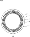
- FIG. 1 is a schematic perspective view of a stator according to Embodiment 1 of the present invention.
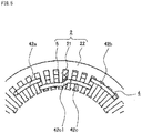
- FIG. 2 is a schematic sectional view taken along the line A-A of the stator in FIG. 1 .
- the stator 100 of the present embodiment comprises an annular stator core 2 and a stator coil 10.
- the stator core 2 is formed of a back yoke 22 which is an outer circumferential part, and teeth 21 which protrude in the radial direction from the inner circumferential surface of the back yoke 22. Slots 5 are formed between the respective teeth 21.
- the stator coil 10 is formed of a plurality of unit coils 4 described later, and three phases of U phase, V phase and W phase are Y-connected.
- the unit coils 4 are inserted in the slots 5 and wound around the teeth 21.
- Each unit coil 4 is partially exposed from the stator core 2 in the axial direction.
- the exposed part side where a first terminal wire 42a and a second terminal wire 42b of each unit coil 4 are present is referred to as a terminal side, and the opposite side is referred to as a anti-terminal side.
- stator core 2 having forty-eight slots 5 and forty-eight teeth 21 is shown as an example, but the numbers of the slots 5 and the teeth 21 are not limited thereto.
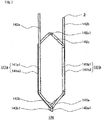
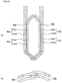
- FIG. 3 is a schematic front view (a) and a schematic perspective view (b) of the unit coil according to Embodiment 1 of the present invention.
- FIG. 4 is a partial schematic view of a cross section along a direction perpendicular to the axial direction, of the stator core in which one unit coil is arranged, according to Embodiment 1 of the present invention.
- the unit coil 4 is formed by winding, substantially in a hexagonal shape, one conductive wire 3 composed of a conductor portion and an insulation film coating the surface of the conductor portion. That is, the coil unit 4 is formed in a concentric-winding manner.
- the unit coil 4 is arranged in two slots 5 across a plurality of teeth 21. That is, the stator coil 10 of the present embodiment is a distributed-winding coil.
- the unit coil 4 comprises: slot-accommodated portions to be respectively accommodated in the two slots 5; coil end portions connecting the slot-accommodated portions; and terminal wires extending from the respective slot-accommodated portions.
- the slot-accommodated portion positioned at the left on the drawing plane is referred to as a first slot-accommodated portion 41a
- the other slot-accommodated portion positioned at the right on the drawing plane is referred to as a second slot-accommodated portion 41b.
- the first slot-accommodated portion 41a and the second slot-accommodated portion 41b are each composed of two lines of the conductive wire 3.
- the first slot-accommodated portion 41a is composed of a first slot-accommodated portion inner-side conductive wire 41a1 positioned on the inner side, and a first slot-accommodated portion outer-side conductive wire 41a2 positioned on the outer side.
- the second slot-accommodated portion 41b is composed of a second slot-accommodated portion inner-side conductive wire 41b1 positioned on the inner side, and a second slot-accommodated portion outer-side conductive wire 41b2 positioned on the outer side.
- the first slot-accommodated portion inner-side conductive wire 41a1 is positioned at a radially inner side of the first slot-accommodated portion outer-side conductive wire 41a2, and the second slot-accommodated portion inner-side conductive wire 41bl is positioned at a radially inner side of the second slot-accommodated portion outer-side conductive wire 41b2.
- the slot 5 in which the first slot-accommodated portion 41a is provided and the slot 5 in which the second slot-accommodated portion 41b is provided are located at positions separated from each other with a predetermined number of teeth therebetween in the radial direction.
- the slot 5 in which the second slot-accommodated portion 41b of one unit coil 4 is provided is located at a position separated from the slot 5 in which the first slot-accommodated portion 41a of the one unit coil 4 is provided, with a predetermined number of teeth therebetween in the clockwise circumferential direction.
- the first slot-accommodated portion 41a is provided in the slot 5 at the left in the circumferential direction
- the second slot-accommodated portion 41b is provided in the slot 5 at the right in the circumferential direction.
- the first slot-accommodated portion inner-side conductive wire 41a1 is located on the radially inner side and the first slot-accommodated portion outer-side conductive wire 41a2 is located on the radially outer side.
- the second slot-accommodated portion inner-side conductive wire 41bl is located on the radially inner side and the second slot-accommodated portion outer-side conductive wire 41b2 is located on the radially outer side.
- the positional relationship in the radial direction between the conductive wires in each slot-accommodated portion of the unit coil 4 is as follows.
- the position of the second slot-accommodated portion inner-side conductive wire 41b1 is shifted outward from the position of the first slot-accommodated portion inner-side conductive wire 41a1 by one line of the conductive wire 3.
- the position of the first slot-accommodated portion outer-side conductive wire 41a2 is shifted outward from the position of the second slot-accommodated portion inner-side conductive wire 41b1 by one line of the conductive wire 3.
- the position of the second slot-accommodated portion outer-side conductive wire 41b2 is shifted outward from the position of the first slot-accommodated portion outer-side conductive wire 41a2 by one line of the conductive wire 3.
- the position of the second slot-accommodated portion outer-side conductive wire 41b2 is shifted outward from the position of the first slot-accommodated portion inner-side conductive wire 41a1 by three lines of the conductive wire 3.
- a gap in which one line of the conductive wire 3 can be inserted is present between the first slot-accommodated portion inner-side conductive wire 41a1 and the first slot-accommodated portion outer-side conductive wire 41a2, and between the first slot-accommodated portion outer-side conductive wire 41a2 and the back yoke 22.
- a gap in which one line of the conductive wire 3 can be inserted is present between the second slot-accommodated portion inner-side conductive wire 41bl and the second slot-accommodated portion outer-side conductive wire 41b2.
- the unit coil 4 has a first terminal wire 42a extending from the first slot-accommodated portion outer-side conductive wire 41a2, and a second terminal wire 42b extending from the second slot-accommodated portion outer-side conductive wire 41b2.
- a coil end portion (referred to as a terminal-side coil end portion) 42c connecting the first slot-accommodated portion inner-side conductive wire 41a1 and the second slot-accommodated portion inner-side conductive wire 41b1, is provided.
- a coil end portion (referred to as a first anti-terminal-side coil end portion) 43a connecting the first slot-accommodated portion outer-side conductive wire 41a2 and the second slot-accommodated portion inner-side conductive wire 41b1, and a coil end portion (referred to as a second anti-terminal-side coil end portion) 43b connecting the first slot-accommodated portion inner-side conductive wire 41a1 and the second slot-accommodated portion outer-side conductive wire 41b2, are provided.
- a coil end portion (referred to as a first anti-terminal-side coil end portion) 43a connecting the first slot-accommodated portion outer-side conductive wire 41a2 and the second slot-accommodated portion inner-side conductive wire 41b1
- a coil end portion (referred to as a first anti-terminal-side coil end portion) 43a connecting the first slot-accommodated portion outer-side conductive wire 41a2 and the second slot-accommodated portion inner-side conductive wire 41
- FIG. 5 is a partial schematic view of the terminal-side end surface of the stator core in which one unit coil is arranged, according to Embodiment 1 of the present invention.
- FIG. 6 is a partial schematic view of the anti-terminal-side end surface of the stator core in which one unit coil is arranged, according to Embodiment 1 of the present invention.
- the terminal-side coil end portion 42c has a lane change portion 42c1 for adjusting the shifting of the second slot-accommodated portion inner-side conductive wire 41b1 radially outward from the first slot-accommodated portion inner-side conductive wire 41a1 by one line of the conductive wire 3. That is, the lane change portion 42c1 crosses the width of one line of the conductive wire 3 in the radial direction.
- the first anti-terminal-side coil end portion 43a has a lane change portion 43a1 for adjusting the shifting of the first slot-accommodated portion outer-side conductive wire 41a2 radially outward from the second slot-accommodated portion inner-side conductive wire 41b1 by one line of the conductive wire 3. That is, the lane change portion 43a1 crosses the width of one line of the conductive wire 3 in the radial direction.
- the second anti-terminal-side coil end portion 43b has a lane change portion 43b1 for adjusting the shifting of the second slot-accommodated portion outer-side conductive wire 41b2 radially outward from the first slot-accommodated portion inner-side conductive wire 41a1 by three lines of the conductive wire 3. That is, the lane change portion 43b1 crosses the width of three lines of the conductive wire 3 in the radial direction.
- the second anti-terminal-side coil end portion 43b is located axially outward with respect to the first anti-terminal-side coil end portion 43a, and crosses the first anti-terminal-side coil end portion 43a.
- the second terminal wire 42b extends from the second slot-accommodated portion outer-side conductive wire 41b2 positioned on the radially outermost side, and the first terminal wire 42a extends from the first slot-accommodated portion outer-side conductive wire 41a2 at a position shifted inward from the radially outermost side by one line of the conductive wire 3.
- the first terminal wire 42a extends from the first slot-accommodated portion outer-side conductive wire 41a2
- the second terminal wire 42b extends from the second slot-accommodated portion outer-side conductive wire 41b2
- the terminal-side coil end portion 42c connects the first slot-accommodated portion inner-side conductive wire 41a1 and the second slot-accommodated portion inner-side conductive wire 41b1.
- first terminal wire 42a may extend from the first slot-accommodated portion inner-side conductive wire 41a1
- the second terminal wire 42b may extend from the second slot-accommodated portion inner-side conductive wire 41b1
- the terminal-side coil end portion 42c may connect the first slot-accommodated portion outer-side conductive wire 41a2 and the second slot-accommodated portion outer-side conductive wire 41b2.
- the first slot-accommodated portion 41a and the second slot-accommodated portion 41b are each formed of two lines of the conductive wire 3.
- the number of lines of the conductive wire forming each slot-accommodated portion may be n within a range that allows formation of the stator coil.
- n is an integer not less than 2.
- the unit coil has (n - 1) number of terminal-side coil end portions, (n - 1) number of first anti-terminal-side coil end portions, and one second anti-terminal-side coil end portion.
- the terminal-side coil end portions and the first anti-terminal-side coil end portions each have a lane change portion crossing the width of one line of the conductive wire. That is, the terminal-side coil end portions and the first anti-terminal-side coil end portions each connect the first slot-accommodated portion conductive wire and the second slot-accommodated portion conductive wire that are shifted from each other by one line of the conductive wire in the radial direction.
- the second anti-terminal-side coil end portion has a lane change portion crossing the width of (2n - 1) lines of the conductive wire. That is, the second anti-terminal-side coil end portion connects the first slot-accommodated portion conductive wire and the second slot-accommodated portion conductive wire that are shifted from each other by (2n - 1) lines of the conductive wire in the radial direction.
- the second anti-terminal-side coil end portion is located axially outward with respect to the first anti-terminal-side coil end portions, and crosses (n - 1) number of the first anti-terminal-side coil end portions 43a.
- the second terminal wire extends from the second slot-accommodated portion conductive wire positioned on the radially outermost side
- the first terminal wire extends from the first slot-accommodated portion conductive wire at a position shifted inward by one line of the conductive wire 3 in the radial direction from the second slot-accommodated portion conductive wire positioned on the radially outermost side.
- the first terminal wire may extend from the first slot-accommodated portion conductive wire positioned on the radially innermost side
- the second terminal wire may extend from the second slot-accommodated portion conductive wire at a position shifted outward by one line of the conductive wire 3 in the radial direction from the first slot-accommodated portion conductive wire positioned on the radially innermost side.
- the conductive wires extending from the terminal wires are not connected in the terminal-side coil end portion.
- the first terminal wire and the second terminal wire are shifted from each other by one line of the conductive wire in the radial direction.
- FIG. 7 is a schematic front view of the conventional unit coil.
- the conventional unit coil 104 is also formed by winding one conductive wire in a lap winding manner, and comprises a first slot-accommodated portion 141a, a second slot-accommodated portion 141b, a coil end portion connecting the slot-accommodated portions, and terminal wires extending from the respective slot-accommodated portions.
- the first slot-accommodated portion 141a is formed by two conductive wires comprising a first slot-accommodated portion inner-side conductive wire 141a1 on the near side on the drawing plane in FIG. 7 , and a first slot-accommodated portion outer-side conductive wire 141a2 on the far side on the drawing plane in FIG. 7 .
- the second slot-accommodated portion 141b is formed by two conductive wires comprising a second slot-accommodated portion inner-side conductive wire 141b1 on the near side on the drawing plane in FIG. 7 , and a second slot-accommodated portion outer-side conductive wire 141b2 on the far side on the drawing plane in FIG. 7 .
- first anti-terminal-side coil end portion 143a connecting the first slot-accommodated portion inner-side conductive wire 141a1 and the second slot-accommodated portion inner-side conductive wire 141b1
- terminal-side coil end portion 142c connecting the second slot-accommodated portion inner-side conductive wire 141b1 and the first slot-accommodated portion outer-side conductive wire 141a2
- second anti-terminal-side coil end portion 143b connecting the first slot-accommodated portion outer-side conductive wire 141a2 and the second slot-accommodated portion outer-side conductive wire 141b2.
- the terminal-side coil end portion 142c has a lane change portion 142c1 crossing the width of one line of the conductive wire 3 in the radial direction.
- the first anti-terminal-side coil end portion 143a has a lane change portion 143a1 crossing the width of one line of the conductive wire 3 in the radial direction.
- the second anti-terminal-side coil end portion 143b has a lane change portion 143b1 crossing the width of one line of the conductive wire 3 in the radial direction.
- the position of the second slot-accommodated portion outer-side conductive wire 141b2 is shifted outward from the position of the first slot-accommodated portion inner-side conductive wire 141a1 by three lines of the conductive wire 3.
- terminal wires there are a first terminal wire 142a extending from the first slot-accommodated portion inner-side conductive wire 141a1, and a second terminal wire 142b extending from the second slot-accommodated portion outer-side conductive wire 141b2. That is, in the radial direction, the position of the first terminal wire 142a and the position of the second terminal wire 142b are shifted from each other by three lines of the conductive wire 3.
- FIG. 8 is a schematic perspective view of a stator intermediate in which the unit coil of the comparative example is mounted to the stator core.
- FIG. 9 is a partial schematic end surface view of the stator intermediate in FIG. 8 as seen from a direction indicated by arrow F.
- each terminal wire is not joined with a terminal wire of another unit coil.
- the first terminal wire 142a of one unit coil 104 is joined with the second terminal wire 142b of the unit coil 104 separated from the first terminal wire 142a with, for example, five slots therebetween in the counterclockwise circumferential direction
- the second terminal wire 142b is joined with the first terminal wire 142a of the unit coil 104 separated from the second terminal wire 142b with, for example, five slots therebetween in the clockwise circumferential direction.
- the first terminal wire 142a of each unit coil 104 and the second terminal wire 142b of another unit coil 104 to be joined with the first terminal wire 142a are not located at the positions opposing to each other in the radial direction.
- the first terminal wire 142a of each unit coil 104 is bent in the counterclockwise direction indicated by arrow L in FIG. 9 .
- the bent first terminal wire 142a is formed into an arc shape substantially parallel with the inner circumferential surface of the stator core 2.
- the inner circumferential surface of the stator core 2 is a surface opposing to the outer circumferential surface of a rotor to be provided when the rotary electric machine is formed.
- the second terminal wire 142b of the unit coil 104 is bent in the clockwise direction indicated by arrow R in FIG. 9 .
- the bent second terminal wire 142b is formed into an arc shape substantially parallel with the inner circumferential surface of the stator core 2.
- the bending of the first terminal wires 142a and the bending of the second terminal wires 142b are performed at the same time for all the unit coils 104.
- FIG. 10 is a schematic perspective view showing the stator intermediate in which each first terminal wire and each second terminal wire to be joined with each other, of the unit coils of the comparative example, are opposed to each other in the radial direction.
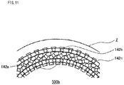
- FIG. 11 is a partial schematic end surface view of the stator intermediate in FIG. 10 as seen from a direction indicated by arrow F.
- the first terminal wire 142a of each unit coil 104 and the second terminal wire 142b of another unit coil 104 are located at the positions opposing to each other in the radial direction.
- each first terminal wire 142a is located away in the radial direction from the second terminal wire 142b of another unit coil 104. Therefore, in order to join the first terminal wire 142a and the second terminal wire 142b, at least one terminal wire of the first terminal wire 142a and the second terminal wire 142b needs to be bent in the radial direction so that the terminal wires are gathered.
- FIG. 12 is a partial schematic perspective view showing the stator intermediate in which the first terminal wire of each unit coil of the comparative example is brought to be gathered with the second terminal wire.
- FIG. 13 is a partial schematic end surface view of the stator intermediate in FIG. 12 as seen from a direction indicated by arrow F.
- FIG. 14 is a partial schematic perspective view showing the stator of the comparative example.
- stator intermediate 500c in which the first terminal wire 142a of each unit coil of the comparative example is brought to be gathered with the second terminal wire 142b as shown in FIG. 12 and FIG. 13 , gathered portions 144a are joined by welding, and the stator 500 of the comparative example as shown in FIG. 14 is obtained.
- welded portions 144c are top portions of the first terminal wire 142a and the second terminal wire 142b. However, without limitation thereto, the welded portions 144c may be any parts of the gathered portions 144a.
- stator coil of the stator 500 of the comparative example at least one terminal wire of the first terminal wire 142a and the second terminal wire 142b crosses over the terminal-side coil end portion. That is, the stator coil has a crossing portion 144b.
- FIG. 15 is a schematic view showing the unit coil according to Embodiment 1 of the present invention in the state in which the unit coil is not yet mounted to the stator core.
- the unit coil 4 having the first terminal wire 42a extending from the first slot-accommodated portion outer-side conductive wire 41a2 without being bent, and the second terminal wire 42b extending from the second slot-accommodated portion outer-side conductive wire 41b2 without being bent as shown in FIG. 15 is mounted to the stator core 2.
- FIG. 16 is a schematic perspective view of a stator intermediate to which the unit coils having the terminal wires that are not bent are mounted, according to Embodiment 1 of the present invention.
- FIG. 17 is a partial schematic end surface view of the stator intermediate in FIG. 16 as seen from a direction indicated by arrow F.
- a plurality of the unit coils 4 are mounted to the stator core 2. At this time, between the conductive wires of the slot-accommodated portion of each unit coil 4, conductive wires of the slot-accommodated portion of another unit coil 4 are inserted.
- FIG. 16 and FIG. 17 show the state in which each terminal wire is not joined with the terminal wire of another unit coil.
- the first terminal wire 42a of one unit coil 4 is joined with the second terminal wire 42b of another unit coil 4 separated from the first terminal wire 42a with, for example, five slots therebetween in the counterclockwise circumferential direction
- the second terminal wire 42b of one unit coil 4 is joined with the first terminal wire 42a of another unit coil 4 separated from the second terminal wire 42b with, for example, five slots therebetween in the clockwise circumferential direction.
- the first terminal wire 42a of each unit coil 4 and the second terminal wire 42b of another unit coil 4 to be joined with the first terminal wire 42a are not located at positions opposing to each other in the radial direction.
- the first terminal wire 42a of each unit coil 4 is bent in the counterclockwise direction indicated by arrow L as shown in FIG. 17 .
- the bent first terminal wire 42a is formed into an arc shape substantially parallel with the inner circumferential surface of the stator core 2.
- the second terminal wire 42b of the unit coil 4 is bent in the clockwise direction indicated by arrow R as shown in FIG. 17 .
- the bent second terminal wire 42b is formed into an arc shape substantially parallel with the inner circumferential surface of the stator core 2.
- the bending of the first terminal wires 42a and the bending of the second terminal wires 42b are performed at the same time for all the unit coils 4.
- FIG. 18 is a schematic perspective view showing the stator intermediate in which each first terminal wire and each second terminal wire to be joined with each other, of the unit coils, are opposed to each other in the radial direction, according to Embodiment 1 of the present invention.
- FIG. 19 is a partial schematic end surface view of the stator intermediate in FIG. 18 as seen from a direction indicated by arrow F.
- the first terminal wire 42a of each unit coil 4 and the second terminal wire 42b of another unit coil 4 to be joined with the first terminal wire 42a are located at the positions opposing to each other in the radial direction.
- first terminal wire 42a of each unit coil 4 and the second terminal wire 42b of another unit coil 4 to be joined with the first terminal wire 42a are in contact with each other in the radial direction.
- portions (referred to as contact portions) 44a that are opposed to each other and in contact with each other are joined by welding, and the stator 100 of the present embodiment is obtained.
- welded portions 44c are top portions of the first terminal wire 42a and the second terminal wire 42b.
- the welded portions 44c may be any parts of the contact portions 44a of the first terminal wire 42a and the second terminal wire 42b.
- stator 100 of the present embodiment it is not necessary to bend, in the radial direction, at least one terminal wire of the first terminal wire 42a and the second terminal wire 42b to gather the terminal wires. Therefore, the number of times for bending the conductive wire 3 forming the coil is decreased and the number of processes in manufacturing of the stator is decreased, whereby the productivity is improved.
- the frequency at which the insulation film of the conductive wire 3 is impaired can be reduced and the coil is less damaged.
- the insulation reliability of the stator is enhanced.
- FIG. 20 is a partial schematic view showing a cross section along a direction perpendicular to the circumferential direction of the stator of the comparative example.
- FIG. 21 is a partial schematic view showing a cross section along a direction perpendicular to the circumferential direction of the stator according to Embodiment 1 of the present invention.
- FIG. 20 and FIG. 21 both show the terminal side of the stator.
- the first terminal wire 142a is bent to be gathered with the second terminal wire 142b, whereby the crossing portion 144b is formed.
- the height of the coil end can be reduced by an amount corresponding to the crossing portion.
- a round wire is used as the conductive wire.
- a rectangular wire may be used instead of the round wire.
- the slot 5 in which the second slot-accommodated portion 41b is provided is located at a position separated from the slot 5 in which the first slot-accommodated portion 41a is provided, with a predetermined number of teeth therebetween in the clockwise circumferential direction.
- the slot 5 in which the second slot-accommodated portion 41b is provided may be located at a position separated from the slot 5 in which the first slot-accommodated portion 41a is provided, with a predetermined number of teeth therebetween in the counterclockwise circumferential direction.
- the first slot-accommodated portion 41a is accommodated in the slot 5 at one of positions separated from each other with a predetermined number of teeth therebetween in the circumferential direction, and the second slot-accommodated portion 41b is accommodated in the slot 5 at the other position.
- a stator according to Embodiment 2 of the present invention comprises stator coils formed as a coil basket, and a stator core mounted to the stator coils.
- a unit coil used in the present embodiment has the same shape as the unit coil 4 of Embodiment 1, and is formed by winding one conductive wire.
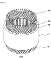
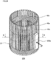
- FIG. 22 is a schematic perspective view showing a stator intermediate in which the stator core is mounted to the coil basket, in the stator according to Embodiment 2 of the present invention.
- each first terminal wire 42a and each second terminal wire 42b have not been bent in the circumferential direction yet and have not been joined by welding or the like yet.
- the stator core 202 is formed by connecting stator core components 202a in the circumferential direction and arranging them in an annular shape.
- FIG. 23 is a schematic perspective view (a) of the stator core component used for the stator according to Embodiment 2 of the present invention, and a schematic view (b) of the end surface of the stator core component in the axial direction.
- the stator core component 202a of the present embodiment comprises a back yoke forming portion 222a, and two teeth 221 protruding from an inner circumferential surface 222c of the back yoke forming portion 222a.
- the side surface at the tip end of each tooth 221 is provided with no protruding portion such as a tip end shoe, and the side surfaces in the circumferential direction of each tooth 221 are flat.
- the gap between the two teeth 221 is a slot 205.
- An end surface (referred to as a tooth circumferential-direction outer-side end surface) 221b on the outer side in the circumferential direction of each tooth 221 is positioned on the inner side in the circumferential direction relative to an end surface (referred to as a back yoke forming portion circumferential-direction end surface) 222b in the circumferential direction of the back yoke forming portion 222a.
- stator core components 202a are joined with each other by causing their back yoke forming portion circumferential-direction end surfaces 222b to come in contact with each other.
- slots 205 are formed also between the tooth circumferential-direction outer-side end surfaces 221b opposing to each other of the teeth 221 of the adjacent stator core components 202a.
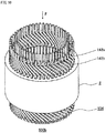
- FIG. 24 is a schematic perspective view of the coil basket used for the stator according to Embodiment 2 of the present invention.
- the coil basket 206 of the present embodiment is formed by arranging a plurality of the unit coils 4 in the circumferential direction.
- the coil basket 206 is formed by inserting, between the conductive wires of the slot-accommodated portion of one unit coil 4, a conductive wire of the slot-accommodated portion of another unit coil 4 adjacent thereto, and by arranging the plurality of unit coils 4 in an annular shape.
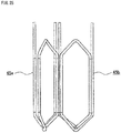
- FIG. 25 is a schematic front view showing two unit coils used for producing the coil basket according to Embodiment 2 of the present invention.
- a unit coil (referred to as an inserting-side unit coil) 45 a of which a conductive wire of the slot-accommodated portion is to be inserted is shown at the left on the drawing plane
- a unit coil (referred to as a receiving-side unit coil) 45b in which the conductive wire is to be inserted between the conductive wires of the slot-accommodated portion is shown at the right on the drawing plane.
- FIG. 26 is a schematic terminal-side top view illustrating the state in which the inserting-side unit coil is arranged with respect to the receiving-side unit coil in an overlapping manner in production of the coil basket according to Embodiment 2 of the present invention.
- the second slot-accommodated portion inner-side conductive wire 41b1 of the inserting-side unit coil 45a is moved while being turned in a direction indicated by arrow S, to pass between the first slot-accommodated portion inner-side conductive wire 41a1 and the first slot-accommodated portion outer-side conductive wire 41a2 of the receiving-side unit coil 45b, and the inserting-side unit coil 45a is arranged.
- the second slot-accommodated portion outer-side conductive wire 41b2 of the inserting-side unit coil 45a is moved while being turned in a direction indicated by arrow S, to pass by the radially outer side of the first slot-accommodated portion outer-side conductive wire 41a2 of the receiving-side unit coil 45b, and the inserting-side unit coil 45a is arranged.
- the inserting-side unit coil 45a and the receiving-side unit coil 45b are arranged to overlap each other so as to be shifted from each other in the circumferential direction.
- FIG. 27 is a schematic front view (a) and a schematic terminal-side top view (b) illustrating the state in which the inserting-side unit coil is arranged with respect to the receiving-side unit coil, in production of the coil basket according to Embodiment 2 of the present invention.
- the first slot-accommodated portion 41a of the inserting-side unit coil 45a is shifted from the first slot-accommodated portion 41a of the receiving-side unit coil 45b by one slot 205 in the counterclockwise circumferential direction
- the second slot-accommodated portion 41b of the inserting-side unit coil 45a is shifted from the second slot-accommodated portion 41b of the receiving-side unit coil 45b by one slot 205 in the counterclockwise circumferential direction.
- the coil basket 206 is formed by arranging the unit coils in an annular shape while overlapping each other in a shifted manner.
- the shift amount corresponding to one slot is such that the angle between two sides connecting the center in the same positions of the unit coil and the overlapping unit coil is 7.5°.
- the number of the slots differs, the shift amount corresponding to one slot also differs, thus the number of the slots is not limited to 7.5°.
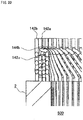
- FIG. 28 is a schematic perspective view illustrating the state in which the stator core components are attached to the coil basket according to Embodiment 2 of the present invention.
- FIG. 29 is a schematic sectional view taken along B-B line of the coil basket in FIG. 28 .
- the teeth 221 of the stator core components 202a are inserted between the slot-accommodated portions of a plurality of unit coils 4 forming the coil basket 206.
- the insertion of the teeth 221 into the coil basket 206 is performed by pressing the stator core components 202a in a direction indicated by arrow P from the outer circumferential side of the coil basket 206 to move the stator core components 202a inwardly in the radial direction.
- stator core components 202a are attached to the coil basket 206, and the stator intermediate 200a shown in FIG. 22 is produced.
- stator intermediate 200a all the slot-accommodated portions are accommodated in the slots 205.
- stator core components 202a attached to the coil basket 206 and arranged in an annular shape with their back yoke forming portion circumferential-direction end surfaces 222b being in contact with each other are integrated by joining the back yoke forming portions 222a by welding or the like.
- the integrated part of the back yoke forming portions 222a becomes a back yoke of the stator core 202, whereby the stator core 202 is formed.
- the first terminal wire 42a and the second terminal wire 42b of each unit coil 4 are bent. Then, the first terminal wire 42a of each unit coil 4 and the second terminal wire 42b of another unit coil 4 are opposed to each other in the radial direction and come in contact with each other.
- first terminal wire 42a of each unit coil 4 and the second terminal wire 42b of another unit coil 4 which are opposed to each other and in contact with each other are joined by welding or the like to complete the stator coil, whereby the stator is manufactured.
- the stator of the present embodiment since the first terminal wire 42a and the second terminal wire 42b of each unit coil 4 are arranged so as to be shifted from each other by one line of the conductive wire in the radial direction, it is possible to cause the first terminal wire 42a of each unit coil 4 and the second terminal wire 42b of another unit coil 4 to be opposing to each other in the radial direction and to be in contact with each other, without providing a crossing portion. Thus, the same effect as in the stator of Embodiment 1 is provided.
- stator is manufactured by inserting the stator core components 202a into the coil basket 206 from the outer circumferential side in the radial direction, the stator core can be easily attached to the stator coil and thus the productivity is improved.
- a load applied to the stator coil is small when the stator core components 202a are inserted into the coil basket 206, thus deterioration in the insulation property of the unit coils 4 can be prevented.
- each stator core component has two teeth, but the number of the teeth is not limited to two.
- a stator according to Embodiment 3 of the present invention comprises stator coils and a stator core to which the stator coils are mounted.
- a unit coil used in the present embodiment has the same shape as the unit coil 4 of Embodiment 1, and is formed by winding one conductive wire.
- a coil basket forming the stator coils is the same as the coil basket 206 of Embodiment 2.
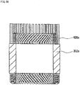
- FIG. 30 is a schematic perspective view showing a stator intermediate in which a contracted coil basket is mounted to the stator core, in the stator according to Embodiment 3 of the present invention.
- each first terminal wire 342a and each second terminal wire 342b have not been bent in the circumferential direction yet and have not been joined by welding or the like yet.
- the stator core 302 shown in FIG. 30 is formed into an inner core 302a located on the radially inner side, and an outer core 302b separate from the inner core 302a and located on the radially outer side.
- the outer core 302b is a back yoke of the stator core 302.
- FIG. 31 is a schematic view of the end surface in the axial direction of the stator core used in the stator according to Embodiment 3 of the present invention.
- the inner core 302a is formed by a plurality of teeth 321 and a plurality of connection portions 321a.
- the plurality of teeth 321 are radially arranged at regular intervals along the circumferential direction.
- Each connection portion 321a connects the radially-inner-side ends of the adjacent teeth 321.
- the radially-inner-side ends of the plurality of teeth 321 and the plurality of connection portions 321a form an annular body.
- the outer core 302b serving as a back yoke of the stator core 302 has a cylindrical shape.
- the inner circumferential surface of the outer core 302b fixes the radially-outer-side ends of the teeth 321 of the inner core 302a.
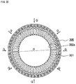
- FIG. 32 is a schematic view of the end surface in the axial direction, showing the state in which the inner core is arranged in the coil basket, according to Embodiment 3 of the present invention.
- the coil basket 306 is produced by the same operation as in Embodiment 2.
- the width in the circumferential direction of the terminal-side coil end portion and the width in the circumferential direction of the anti-terminal-side coil end portion are increased, and the inner diameter of the coil basket 306 is greater than the outer diameter D of the inner core 302a.
- the inner core 302a is arranged on the inner circumferential side of the coil basket 306.
- the coil basket 306 is tightened from the outer circumferential part indicated by arrows Q, whereby the bending angles of the coil end portions on the terminal side and the anti-terminal side in each unit coil are decreased and the unit coil becomes a contracted unit coil in which the widths in the circumferential direction of the coil end portions are reduced.
- the coil basket 306 is contracted to reduce its inner diameter, the teeth 321 are inserted between the slot-accommodated portions of the unit coils, whereby the coil basket (referred to as a contracted coil basket) 306a that has been contracted is mounted to the inner core 302a.
- FIG. 33 is a schematic view of the end surface in the axial direction, showing the state in which the contracted coil basket is mounted to the inner core, according to Embodiment 3 of the present invention.
- the inner core 302a to which the contracted coil basket 306a is mounted is pressed into the outer core 302b, and the stator intermediate 300a shown in FIG. 30 is produced.
- the first terminal wire 342a and the second terminal wire 342b of each contracted unit coil are bent. Then, the first terminal wire 342a of each contracted unit coil and the second terminal wire 342b of another contracted unit coil to be joined with the first terminal wire 342a are opposed to each other in the radial direction and are in contact with each other.
- first terminal wire 342a of each contracted unit coil and the second terminal wire 342b of another contracted unit coil which are opposed to each other and are in contact with each other are joined by welding or the like to complete the stator coil, whereby the stator is manufactured.
- the first terminal wire 342a and the second terminal wire 342b of each arranged unit coil are arranged so as to be shifted from each other by one line of the conductive wire in the radial direction, it is possible to cause the first terminal wire 342a of each arranged unit coil and the second terminal wire 342b of another arranged unit coil to be opposed to each other in the radial direction and to be in contact with each other, without providing a crossing portion.
- the same effect as in the stator of Embodiment 1 is provided.
- stator core 302 used as the stator of the present embodiment since the radially-inner-side ends of the teeth 321 are connected by the connection portions 321a, the accuracy of the shape of the inner circumference of the stator core is enhanced. Therefore, in the rotary electric machine using the stator of the present embodiment, cogging torque and torque ripple are reduced.
- a stator according to Embodiment 4 of the present invention also comprises stator coils and a stator core to which the stator coils are mounted.
- the stator core used in the present embodiment is the same as the stator core 302 of Embodiment 3.
- the shape of the unit coil and the shape of the coil basket are different from those in Embodiment 3.
- the number of lines of the conductive wire in each slot-accommodated portion, the number of the coil end portions, and the width which the lane change portion crosses are the same as those in Embodiment 3.
- Each unit coil is formed by winding one conductive wire.
- FIG. 34 is a schematic front view of the unit coil according to Embodiment 4 of the present invention.
- a width (referred to as the width of the terminal-side coil end portion) E1 in the circumferential direction of a terminal-side coil end portion 442c is greater than a width (referred to as the width of the anti-terminal-side coil end portion) E2 in the circumferential direction of a first anti-terminal-side coil end portion 443a and a second anti-terminal-side coil end portion 443b.
- the terminal-side coil end portion 442c has a lane change portion 442c1
- the first anti-terminal-side coil end portion 443a has a lane change portion 443a1
- the second anti-terminal-side coil end portion 443b has a lane change portion 443b1.
- a first slot-accommodated portion 441a is composed of a first slot-accommodated portion inner-side conductive wire 441a1 and a first slot-accommodated portion outer-side conductive wire 441a2.
- a second slot-accommodated portion 441b is composed of a second slot-accommodated portion inner-side conductive wire 441b1 and a second slot-accommodated portion outer-side conductive wire 441b2.
- FIG. 35 is a schematic side view of one unit coil forming the coil basket according to Embodiment 4 of the present invention.
- first and second terminal wires 442a and 442b and a terminal-side coil end portion 442c are bent, inward in the radial direction of the coil basket as indicated by arrow M, with respect to the extended line from the first and second slot-accommodated portions 441a and 441b.
- first and second anti-terminal-side coil end portions 443a and 443b are bent, outward in the radial direction of the coil basket as indicated by arrow N, with respect to the extended line from the first and second slot-accommodated portions 441a and 441b.
- a distance T1 between the central axis X of the coil basket 406 and the terminal-side end of the slot-accommodated portion is greater than a distance T2 between the central axis X of the coil basket 406 and the anti-terminal-side end of the slot-accommodated portion.
- each unit coil 404 forming the coil basket 406 of the present embodiment the slot-accommodated portions 441a and 441b are inclined.
- the coil basket 406 of the present embodiment is produced by the same method as in the coil basket 206 of Embodiment 2.
- the conductive wire of the second slot-accommodated portion 441b of the inserting-side unit coil 404 passes between the conductive wires of the first slot-accommodated portion 441a of the receiving-side unit coil 404, thereby the unit coils 404 are overlapped each other so as to be shifted from each other in the circumferential direction. Then, all the unit coils 404 are overlapped each other so as to be shifted from each other in the circumferential direction and are arranged in an annular shape, whereby the coil basket 406 is produced.
- FIG. 36 is a schematic perspective view of the coil basket used as the stator according to Embodiment 4 of the present invention.
- the inner diameter on the terminal side of the coil basket 406 of the present embodiment is greater than the inner diameter on the anti-terminal side.
- the inner diameter on the terminal side of the coil basket 406 is greater than the outer diameter D of the inner core 302a shown in FIG. 32 .
- the inner diameter on the anti-terminal side of the coil basket 406 is greater than a diameter (referred to as an inter-slot diameter) G between the bottoms of the slots 305 opposed to each other in the inner core 302a shown in FIG. 31 .
- the difference between the inner diameter on the terminal side of the coil basket 406 and the outer diameter D of the inner core 302a, and the difference between the inner diameter on the anti-terminal side of the coil basket 406 and the inter-slot diameter G are small.
- the coil basket 406 is mounted to the inner core 302a.
- FIG. 37 is a schematic sectional view showing the state in which the inner core is arranged in the coil basket according to Embodiment 4 of the present invention.
- FIG. 38 is a schematic perspective view showing the inner core to which the contracted coil basket is mounted, according to Embodiment 4 of the present invention.
- FIG. 39 is a schematic view showing a cross section along a direction perpendicular to the radial direction, of the inner core to which the contracted coil basket is mounted in FIG. 38 .
- the inner core 302a is inserted from the terminal side of the coil basket 406. Then, as shown in FIG. 37 , a force is applied to the coil basket 406 from the outer circumferential side as indicated by arrows Q.
- the teeth 321 of the inner core 302a are inserted into the gaps between the slot-accommodated portions of the coil basket 406, and the coil basket 406 is contracted, whereby all the slot-accommodated portions are accommodated in the slots 305.
- FIG. 40 is a schematic front view showing each contracted unit coil forming the contracted coil basket according to Embodiment 4 of the present invention.
- the width in the circumferential direction of the terminal-side coil end portion 442c of the unit coil 404 is reduced.
- the unit coil 404 becomes the contracted unit coil 404a in which the width in the circumferential direction of the terminal-side coil end portion 442c is almost the same as the width E2 in the circumferential direction of the anti-terminal-side coil end portions.
- stator intermediate 400a is produced.
- FIG. 41 is a schematic perspective view showing the stator intermediate according to Embodiment 4 of the present invention.
- the first terminal wire 442a and the second terminal wire 442b of each contracted unit coil 404a are bent. Then, the first terminal wire 442a of each contracted unit coil 404a and the second terminal wire 442b of another contracted unit coil 404a to be joined with the first terminal wire 442a are opposing to each other in the radial direction and are in contact with each other.
- first terminal wire 442a of each contracted unit coil 404a and the second terminal wire 442b of another contracted unit coil 404a which are opposed to each other and in contact with each other are joined by welding or the like, and the stator coil is completed, whereby the stator is manufactured.
- the first terminal wire 442a and the second terminal wire 442b of each arranged unit coil are arranged so as to be shifted from each other by one line of the conductive wire in the radial direction, it is possible to cause the first terminal wire 442a of each arranged unit coil and the second terminal wire 442b of another arranged unit coil to be opposing to each other in the radial direction and to be in contact with each other, without providing a crossing portion.
- the same effect as in the stator of Embodiment 1 is provided.
- stator core is the same as that in Embodiment 3, the accuracy of the shape of the inner circumference of the stator core is enhanced, and thus, also in the rotary electric machine using the stator of the present embodiment, cogging torque and torque ripple are reduced.
- the terminal-side coil end portion of each unit coil 404 is deformed. But the anti-terminal-side coil end portion is not deformed. Therefore, a force applied to the unit coil is small, and the insulation reliability of the coil is enhanced.
- a stator according to Embodiment 5 of the present invention is the same as the stator of Embodiment 4 except that the shape of each unit coil forming a coil basket is different.
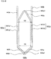
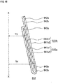
- FIG. 42 is a schematic side view of one unit coil forming the coil basket according to Embodiment 5 of the present invention.
- FIG. 43 is a schematic sectional view showing the state in which an inner core is arranged in the coil basket used for the stator according to Embodiment 5 of the present invention.
- the inner core 302a in FIG. 43 is arranged by being inserted into the coil basket 506 from the terminal side.
- the unit coil 504 shown in FIG. 42 which is used for the coil basket 506, is the same as the unit coil 404 except that first and second terminal wires 542a and 542b, a terminal-side coil end portion 542c, and first and second anti-terminal-side coil end portions 543a and 543b are not bent in the radial direction of the coil basket with respect to the extended line from first and second slot-accommodated portions 541a and 541b.
- the first slot-accommodated portion 541a is composed of a first slot-accommodated portion inner-side conductive wire 541a1 and a first slot-accommodated portion outer-side conductive wire 541a2.
- the second slot-accommodated portion 541b is composed of a second slot-accommodated portion inner-side conductive wire 541b1 and a second slot-accommodated portion outer-side conductive wire 541b2.
- the process for forming a contracted coil basket and mounting the contracted coil basket to the inner core 302a, the process for pressing the inner core 302a to which the contracted coil basket is mounted, into the outer core 302b, to produce a stator intermediate, and the process for joining the first terminal wire 542a of each contracted unit coil and the second terminal wire 542b of another contracted unit coil to be joined with the first terminal wire 542a, are the same as processes in manufacturing of the stator of Embodiment 4.
- stator using the coil basket 506 of the present embodiment provides the same effect as in the stator using the coil basket 406.
- first and second terminal wires 542a and 542b, the terminal-side coil end portion 542c, and the first and second anti-terminal-side coil end portions 543a and 543b are not bent in the radial direction of the coil basket, the number of parts of the unit coil that are bent is decreased. Thus, the number of processes for manufacturing the unit coil can be decreased, and the productivity is further improved. In addition, the frequency at which the insulation film of the conductive wire 3 is damaged can be reduced, whereby damage on the coil is reduced and the insulation reliability of the stator is further improved.
- a stator according to Embodiment 6 of the present invention also comprises stator coils and a stator core to which the stator coils are mounted.
- the stator core used in the present embodiment is the same as the stator core 302 of Embodiment 3.
- the shape of a unit coil and the shape of a coil basket are different from those in Embodiment 4.
- the number of lines of the conductive wire in each slot-accommodated portion, the number of the coil end portions, and the width which a lane change portion crosses are the same as those in Embodiment 4.
- Each unit coil is formed by winding one conductive wire.
- FIG. 44 is a schematic front view of the unit coil according to Embodiment 6 of the present invention.
- a width (referred to as the width of the anti-terminal-side coil end portion) E4 in the circumferential direction of a first anti-terminal-side coil end portion 643a and a second anti-terminal-side coil end portion 643b is greater than a width (referred to as the width of the terminal-side coil end portion) E3 in the circumferential direction of a terminal-side coil end portion 642c.
- the terminal-side coil end portion 642c has a lane change portion 642c1
- the first anti-terminal-side coil end portion 643a has a lane change portion 643a1
- the second anti-terminal-side coil end portion 643b has a lane change portion 643b1.
- a first slot-accommodated portion 641a is composed of a first slot-accommodated portion inner-side conductive wire 641a1 and a first slot-accommodated portion outer-side conductive wire 641a2.
- a second slot-accommodated portion 641b is composed of a second slot-accommodated portion inner-side conductive wire 641b1 and a second slot-accommodated portion outer-side conductive wire 641b2.
- FIG. 45 is a schematic side view of one unit coil forming the coil basket according to Embodiment 6 of the present invention.
- first and second terminal wires 642a and 642b, a terminal-side coil end portion 642c, and first and second anti-terminal-side coil end portions 643a and 643b are not bent in the radial direction of the coil basket 606 with respect to the extended line from the first and second slot-accommodated portions 641a and 641b.
- a distance T4 between the central axis X of the coil basket 606 and the anti-terminal-side end of the slot-accommodated portion is greater than a distance T3 between the central axis X of the coil basket 606 and the terminal-side end of the slot-accommodated portion.
- the coil basket 606 of the present embodiment is produced by the same method as in the coil basket 206 of Embodiment 2.
- the conductive wire of the second slot-accommodated portion 641b of the inserting-side unit coil 604 passes between the conductive wires of the first slot-accommodated portion 641a of the receiving-side unit coil 604, thereby the unit coils 604 are overlapped each other so as to be shifted from each other in the circumferential direction. Then, all the unit coils 604 are overlapped each other so as to be shifted from each other in the circumferential direction and are arranged in an annular shape, whereby the coil basket 606 is produced.
- the coil basket 606 is mounted to the inner core 302a.
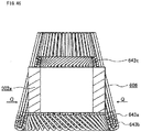
- FIG. 46 is a schematic sectional view showing the state in which the inner core is inserted into the coil basket used for the stator according to Embodiment 6 of the present invention.
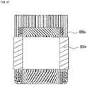
- FIG. 47 is a schematic sectional view showing the inner core to which a contracted coil basket is mounted, according to Embodiment 6 of the present invention.
- the inner diameter of the anti-terminal side of the coil basket 606 of the present embodiment is greater than the inner diameter of the terminal side.
- the inner diameter of the anti-terminal side of the coil basket 606 is greater than the outer diameter D of the inner core 302a shown in FIG. 32 .
- the inner diameter of the terminal side of the coil basket 606 is greater than the inter-slot diameter G of the inner core 302 shown in FIG. 31 .
- the difference between the inner diameter of the anti-terminal side of the coil basket 606 and the outer diameter D of the inner core 302a, and the difference between the inner diameter of the terminal side of the coil basket 606 and the inter-slot diameter G, are small.
- the inner core 302a is inserted from the anti-terminal side of the coil basket 606, whereby the state in which the inner core 302a is inserted into the coil basket 606 as shown in FIG. 46 is obtained.
- FIG. 48 is a schematic front view showing each contracted unit coil forming the contracted coil basket according to Embodiment 6 of the present invention.
- the width in the circumferential direction of the first and second anti-terminal-side coil end portions 643a and 643b of the unit coil 604 is reduced.
- the contracted unit coil 604a is obtained in which the width in the circumferential direction of the anti-terminal-side coil end portions is the same as the width E3 in the circumferential direction of the terminal-side coil end portion.
- the inner core 302a to which the contracted coil basket 606a is mounted is pressed into the outer core 302b (not shown), and a stator intermediate (not shown) is produced.
- the first terminal wire 642a and the second terminal wire 642b of each contracted unit coil 604a are bent. Then, the first terminal wire 642a of each contracted unit coil 604a and the second terminal wire 642b of another contracted unit coil 604a to be joined with the first terminal wire 642a are opposing to each other in the radial direction and are in contact with each other.
- first terminal wire 642a of each contracted unit coil 604a and the second terminal wire 642b of another contracted unit coil 604a which are opposed to each other and in contact with each other are joined by welding or the like, and the stator coil is completed, whereby the stator is manufactured.
- the first terminal wire 642a and the second terminal wire 642b of each arranged unit coil are arranged so as to be shifted from each other by one line of the conductive wire in the radial direction, it is possible to cause the first terminal wire 642a of each arranged unit coil and the second terminal wire 642b of another arranged unit coil to be opposing to each other in the radial direction and to be in contact with each other, without providing a crossing portion.
- the same effect as in the stator of Embodiment 4 is provided.
- stator core is the same as that in Embodiment 3, the accuracy of the shape of the inner circumference of the stator core is enhanced, and thus, also in the rotary electric machine using the stator of the present embodiment, cogging torque and torque ripple are reduced.
- each unit coil 604 is deformed. But the terminal-side coil end portion is not deformed. Therefore, a force applied to the unit coil is small, and the insulation reliability of the coil is enhanced.
- the first and second terminal wires 642a and 642b and the terminal-side coil end portion 642c may be bent outward in the radial direction of the coil basket with respect to the extended line from the first and second slot-accommodated portions 641a and 641b, and the first and second anti-terminal-side coil end portions 643a and 643b may be bent inward in the radial direction of the coil basket with respect to the extended line from the first and second slot-accommodated portions 641a and 641b.
- FIG. 49 is a schematic side sectional view of a rotary electric machine according to Embodiment 7 of the present invention.
- the rotary electric machine 700 of the present embodiment comprises the stator 100 of Embodiment 1, a rotor 61 arranged on the inner circumferential side of the stator 100 with a predetermined gap therebetween, and a rotary shaft 62 inserted in the axial direction through the center of the rotor 61 and fixing the rotor 61.
- the rotary shaft 62 is rotatably held by bearings 63 provided in the housing 60.
- the stator used for the rotary electric machine 700 of the present embodiment may be the stator of any one of Embodiments 2 to 6.
- the rotary electric machine 700 of the present embodiment is excellent in insulation reliability and productivity because the stator thereof is the stator of any one of embodiments 1 to 6.
- the method for manufacturing the rotary electric machine according to the present embodiment includes: a process for manufacturing the stator 100 by the method described in Embodiment 1; and a process for inserting the rotor 61 fixed to the rotary shaft 62 by, for example, shrink fit, into a space on the inner circumferential side of the manufactured stator 100, from the axial direction.
- the stator is manufactured by the method described in Embodiment 1.
- the stator may be manufactured by the method described in any one of Embodiments 2 to 6.
- the stator is manufactured by the method described in any one of Embodiments 1 to 6, the rotary electric machine that is excellent in insulation reliability and productivity can be obtained.
- the stator of the present invention and the rotary electric machine using the stator are excellent in insulation reliability and productivity, and thus are applicable to industrial apparatuses which require cost reduction and high reliability.
Claims (11)
- Stator (100), der Folgendes aufweist:- einen Statorkern (2), der eine Vielzahl von Zähnen (21) und eine Vielzahl von Schlitzen (5) aufweist, die in Umfangsrichtung angeordnet sind; und- Statorspulen (10), die im Statorkern (2) angeordnet und mittels einer verteilten Wicklung gewickelt sind,wobei die Statorspule (10) mittels einer Vielzahl von Einheitsspulen (4) ausgebildet ist, die derart angeordnet sind, dass sie in Umfangsrichtung gegeneinander versetzt sind, wobei die Einheitsspulen (4) jeweils durch Wickeln eines leitenden Drahtes (3) ausgebildet sind,
wobei die Einheitsspulen (4) Folgendes aufweisen:einen ersten im Schlitz angeordneten Bereich (41a); einen zweiten im Schlitz angeordneten Bereich (41b); einen ersten Anschlussdraht (42a), der sich von dem ersten im Schlitz angeordneten Bereich (41a) aus erstreckt; einen zweiten Anschlussdraht (42b), der sich von dem zweiten im Schlitz angeordneten Bereich (41b) aus erstreckt; einen anschlussseitigen Spulenendbereich (42c), der den ersten im Schlitz angeordneten Bereich (41a) und den zweiten im Schlitz angeordneten Bereich (41b) verbindet, und zwar auf einer Anschlussseite, in der der erste Anschlussdraht (42a) und der zweite Anschlussdraht (42b) vorliegen; und anti-anschlussseitige Spulenendbereiche (43a, 43b), die den ersten im Schlitz angeordneten Bereich (41a) und den zweiten im Schlitz angeordneten Bereich (41b) verbinden, und zwar auf einer Anti-Anschlussseite gegenüber von der Anschlussseite in axialer Richtung,wobei der erste im Schlitz angeordnete Bereich (41a) in dem Schlitz (5) an einer von Positionen angeordnet ist, die mit einer vorbestimmten Anzahl der Zähne dazwischen in Umfangsrichtung voneinander getrennt sind, undwobei der zweite im Schlitz angeordnete Bereich (41b) in dem Schlitz (5) an der anderen Position von den Positionen angeordnet ist, die mit der vorbestimmten Anzahl der Zähne dazwischen in Umfangsrichtung voneinander getrennt sind,wobei der erste im Schlitz angeordnete Bereich (41a) und der zweite im Schlitz angeordnete Bereich (41b) jeweils mittels n (n ist eine ganze Zahl nicht kleiner als 2) Leitungen des leitenden Drahts (3) ausgebildet sind,wobei der anschlussseitige Spulenendbereich (42c) mittels (n - 1) Leitungen des leitenden Drahts (3) ausgebildet ist,wobei die anti-anschlussseitigen Spulenendbereiche mittels eines ersten anti-anschlussseitigen Spulenendbereichs (43a) und eines zweiten anti-anschlussseitigen Spulenendbereichs (43b) ausgebildet sind, wobei der erste anti-anschlussseitige Spulenendbereich (43a) mittels (n - 1) Leitungen des leitenden Drahts (3) ausgebildet ist, wobei der zweite anti-anschlussseitige Spulenendbereich (43b) mittels einer Leitung des leitenden Drahts (3) ausgebildet ist,wobei Spalte, die einer Leitung des leitenden Drahtes (3) in radialer Richtung entsprechen, zwischen den jeweiligen Leitungen des leitenden Drahts (3) des ersten im Schlitz angeordneten Bereichs (41a) und zwischen den jeweiligen Leitungen des leitenden Drahts (3) des zweiten im Schlitz angeordneten Bereichs (41b) angeordnet sind,wobei die (n - 1) Leitungen des leitenden Drahts (3) des anschlussseitigen Spulenendbereichs (42c) und die (n - 1) Leitungen des leitenden Drahts (3) des ersten anti-anschlussseitigen Spulenendbereichs (43a) jeweils den entsprechenden leitenden Draht des ersten im Schlitz angeordneten Bereichs (41a) und den entsprechenden leitenden Draht des zweiten im Schlitz angeordneten Bereichs (41b) verbinden, die um eine Leitung des leitenden Drahts (3) in radialer Richtung gegeneinander versetzt sind,dadurch gekennzeichnet,dass die eine Leitung des leitenden Drahts des zweiten anti-anschlussseitigen Spulenendbereichs (43b) den entsprechenden leitenden Draht des ersten im Schlitz angeordneten Bereichs (41a) und den entsprechenden leitenden Draht des zweiten im Schlitz angeordneten Bereichs (41b) verbindet, die um (2n - 1) Leitungen des leitenden Drahtes (3) in radialer Richtung gegeneinander versetzt sind,dass der erste Anschlussdraht (42a) und der zweite Anschlussdraht (42b) um eine Leitung des leitenden Drahtes (3) in radialer Richtung gegeneinander versetzt sind, unddass der erste Anschlussdraht (42a) und der zweite Anschlussdraht (42b) von jeweils unterschiedlichen Einheitsspulen der Einheitsspulen (4) miteinander verbunden sind. - Stator nach Anspruch 1,
wobei die Anzahl n von Leitungen des leitenden Drahts (3), die den ersten im Schlitz angeordneten Bereich (41a) und den zweiten im Schlitz angeordneten Bereich (41b) ausbilden, nicht kleiner als 2 und nicht größer als die Anzahl der Leitungen des leitenden Drahts ist, die in den Schlitzen (5) angeordnet werden können. - Stator nach Anspruch 1,
wobei der Statorkern (202) durch Anordnen von Statorkern-Komponenten (202a) in einer Ringform ausgebildet ist, die einen ein rückseitiges Joch ausbildenden Bereich (222a) und einen Zahn (221) aufweisen, der von einer inneren Umfangsfläche des das rückseitige Joch ausbildenden Bereichs (222a) aus vorsteht,
wobei die Statorspulen (10) einen Spulenkorb (206) bilden, der durch Anordnen einer Vielzahl von Einheitsspulen (4) in Umfangsrichtung ausgebildet ist,
wobei der Spulenkorb (206) dadurch ausgebildet ist, dass bewirkt wird, dass der leitende Draht (3) des zweiten im Schlitz angeordneten Bereichs (41b) von jeder Einheitsspule (4) zwischen den entsprechenden Leitungen des leitenden Drahts (3) des ersten im Schlitz angeordneten Bereichs (41a) der anderen Einheitsspule (4) hindurchgeht, so dass jede Einheitsspule und die andere Einheitsspule einander derart überlappen, dass sie in Umfangsrichtung gegeneinander versetzt sind, und
wobei die Zähne (221) von der äußeren Umfangsseite in den Spulenkorb (206) eingesetzt werden und alle im Schlitz angeordneten Bereiche in den Schlitzen (205) angeordnet sind, die zwischen den Zähnen (221) ausgebildet sind. - Stator nach Anspruch 1,
wobei der Statorkern (302) mittels eines inneren Kerns (302a), der auf einer radial inneren Seite angeordnet ist, und eines äußeren Kerns (302b) ausgebildet ist, der von dem inneren Kern (302a) getrennt und auf einer radial äußeren Seite angeordnet ist,
wobei der innere Kern (302a) mittels einer Vielzahl von den Zähnen (321), die in regelmäßigen Abständen entlang der Umfangsrichtung radial angeordnet sind, und mittels Verbindungsbereichen (321a) ausgebildet ist, die radial innenseitige Enden der benachbarten Zähne verbinden;
wobei die Enden der Zähne (321) und die Verbindungsbereiche (321a) einen ringförmigen Körper ausbilden, wobei die Schlitze (305) zwischen den benachbarten Zähnen (321) ausgebildet sind;
wobei der äußere Kern (302b) eine zylindrische Form aufweist, und eine innere Umfangsfläche des äußeren Kerns (302b) radial außenseitige Enden der Zähne (321) des inneren Kerns (302a) festlegt,
wobei die Statorspulen (10) einen kontrahierten Spulenkorb (306a) bilden, der durch Kontrahieren eines Spulenkorbes (306) in radialer Richtung erhalten wird, der durch Anordnen einer Vielzahl von den Einheitsspulen (4) in Umfangsrichtung ausgebildet ist,
wobei der Spulenkorb (306) dadurch ausgebildet ist, dass bewirkt wird, dass der leitende Draht (3) des zweiten im Schlitz angeordneten Bereichs (41b) von jeder Einheitsspule (4) zwischen den entsprechenden Leitungen des leitenden Drahts (3) des ersten im Schlitz angeordneten Bereichs (41a) der anderen Einheitsspule (4) hindurchgeht, so dass jede Einheitsspule und die andere Einheitsspule einander derart überlappen, dass sie in Umfangsrichtung gegeneinander versetzt sind, und
wobei der kontrahierte Spulenkorb (306a) an dem inneren Kern (302a) angebracht ist und alle im Schlitz angeordneten Bereiche (41a, 41b) in den Schlitzen (305) angeordnet sind, und
wobei der innere Kern (302a), an dem der kontrahierte Spulenkorb (306a) angebracht ist, an dem äußeren Kern (302b) festlegt ist. - Stator nach Anspruch 1,
wobei der Statorkern (302) mittels eines inneren Kerns (302a), der auf einer radial inneren Seite angeordnet ist, und eines äußeren Kerns (302b) ausgebildet ist, der von dem inneren Kern (302a) getrennt und auf einer radial äußeren Seite angeordnet ist,
wobei der innere Kern (302a) mittels einer Vielzahl von den Zähnen (321), die in regelmäßigen Abständen entlang der Umfangsrichtung radial angeordnet sind, und mittels Verbindungsbereichen (321a) ausgebildet ist, die radial innenseitige Enden der benachbarten Zähne verbinden;
wobei die Enden der Zähne (321) und die Verbindungsbereiche (321a) einen ringförmigen Körper ausbilden, wobei die Schlitze (305) zwischen den benachbarten Zähnen ausgebildet sind;
wobei der äußere Kern (302b) eine zylindrische Form aufweist, und eine innere Umfangsfläche des äußeren Kerns (302b) radial außenseitige Enden der Zähne (321) des inneren Kerns (302a) festlegt,
wobei die Statorspulen (10) einen kontrahierten Spulenkorb (406a) bilden, der durch Kontrahieren eines Spulenkorbs (406) in radialer Richtung erhalten wird, der durch Anordnen einer Vielzahl von den Einheitsspulen (404) in Umfangsrichtung ausgebildet ist,
wobei der Spulenkorb (406) dadurch ausgebildet ist, dass bewirkt wird, dass der leitende Draht (3) des zweiten im Schlitz angeordneten Bereichs (441b) von jeder Einheitsspule (404) zwischen den entsprechenden Leitungen des leitenden Drahts (3) des ersten im Schlitz angeordneten Bereichs (441a) der anderen Einheitsspule (404) hindurchgeht, so dass jede Einheitsspule und die andere Einheitsspule einander derart überlappen, dass sie in Umfangsrichtung gegeneinander versetzt sind, und der Durchmesser des Spulenkorbs auf der Anschlussseite größer ist als der Durchmesser des Spulenkorbs auf der Anti-Anschlussseite, wobei die Breite (E1) in Umfangsrichtung des anschlussseitigen Spulenendbereichs (442c) von jeder Einheitsspule (404) größer ist als die Breite in Umfangsrichtung des anti-anschlussseitigen Spulenendbereichs (443a),
wobei der kontrahierte Spulenkorb (406a) an dem inneren Kern (302a) angebracht ist und alle im Schlitz angeordneten Bereiche (441a, 441b) in den Schlitzen (305) angeordnet sind, und
wobei der innere Kern (302a), an dem der kontrahierte Spulenkorb (406a) angebracht ist, an dem äußeren Kern (302b) befestigt ist. - Stator nach Anspruch 5,
wobei jede Einheitsspule (404) derart ausgebildet ist, dass, bezogen auf eine verlängerte Leitung von dem ersten im Schlitz angeordneten Bereich (441a) und eine verlängerte Leitung von dem zweiten im Schlitz angeordneten Bereich (441b), der erste Anschlussdraht (442a), der zweite Anschlussdraht (442b) und der anschlussseitige Spulenendbereich (442c) in radialer Richtung des Spulenkorbes nach innen gebogen sind, und
wobei der erste anti-anschlussseitigen Spulenendbereich (443a) und der zweite anti-anschlussseitigen Spulenendbereich (443b) in radialer Richtung des Spulenkorbes nach außen gebogen sind. - Stator nach Anspruch 5,
wobei jede Einheitsspule (504) derart ausgebildet ist, dass, bezogen auf eine verlängerte Leitung von dem ersten im Schlitz angeordneten Bereich (541a) und eine verlängerte Leitung von dem zweiten im Schlitz angeordneten Bereich (541b), der erste Anschlussdraht (542a), der zweite Anschlussdraht (542b), der anschlussseitige Spulenendbereich (542c), der erste anti-anschlussseitigen Spulenendbereich (543a) und der zweite anti-anschlussseitige Spulenendbereich (543b) nicht in radialer Richtung des Spulenkorbes (506) gebogen sind. - Stator nach Anspruch 1,
wobei der Statorkern (302) mittels eines inneren Kerns (302a), der auf einer radial inneren Seite angeordnet ist, und eines äußeren Kerns (302b), der von dem inneren Kern (302a) getrennt und auf einer radial äußeren Seite angeordnet ist, ausgebildet ist,
wobei der innere Kern (302a) mittels einer Vielzahl der Zähne (321) ausgebildet ist, die in regelmäßigen Abständen entlang der Umfangsrichtung radial angeordnet sind, und mittels Verbindungsbereichen (321a), die radial innenseitige Enden der benachbarten Zähne verbinden; wobei die Enden der Zähne (321) und die Verbindungsbereiche (321a) einen ringförmigen Körper ausbilden, wobei die Schlitze (305) zwischen den benachbarten Zähnen ausgebildet sind;
wobei der äußere Kern (302b) eine zylindrische Form aufweist, und eine innere Umfangsfläche des äußeren Kerns (302b) radial außenseitige Enden der Zähne (321) des inneren Kerns (302a) festlegt,
wobei die Statorspulen (10) einen kontrahierten Spulenkorb (606a) bilden, der durch Kontrahieren eines Spulenkorbes (606) in radialer Richtung erhalten wird, der durch Anordnen einer Vielzahl von den Einheitsspulen (604) in Umfangsrichtung ausgebildet wird,
wobei der Spulenkorb (606) dadurch ausgebildet ist, dass bewirkt wird, dass der leitende Draht (3) des zweiten im Schlitz angeordneten Bereichs (641b) von jeder Einheitsspule (604) zwischen den entsprechenden Leitungen des leitenden Drahts (3) des ersten im Schlitz angeordneten Bereichs (641a) der anderen Einheitsspule (604) hindurchgeht, so dass jede Einheitsspule und die andere Einheitsspule einander derart überlappen, dass sie in Umfangsrichtung gegeneinander versetzt sind, und der Durchmesser (T4) des Spulenkorbs auf der Anti-Anschlussseite größer ist als der Durchmesser (T3) des Spulenkorbes auf der Anschlussseite, wobei die Breite (E4) in Umfangsrichtung des anti-anschlussseitigen Spulenendbereichs (643a, 643b) von jeder Einheitsspule (604) größer ist als die Breite (E3) in Umfangsrichtung des anschlussseitigen Spulenendbereichs (642c),
wobei der kontrahierte Spulenkorb (606a) an dem inneren Kern (302a) angebracht ist und alle im Schlitz angeordneten Bereiche (641a, 641b) in den Schlitzen (305) angeordnet sind, und
wobei der innere Kern (302a), an dem der kontrahierte Spulenkorb (606a) montiert ist, an dem äußeren Kern (302b) befestigt ist. - Stator nach Anspruch 8,
wobei jede Einheitsspule (604) derart ausgebildet ist, dass, bezogen auf eine verlängerte Leitung von dem ersten im Schlitz angeordneten Bereich (641a) und eine verlängerte Leitung von dem zweiten im Schlitz angeordneten Bereich (641b), der erste Anschlussdraht (642b), der zweite Anschlussdraht (642b) und der anschlussseitige Spulenendbereich (642c) in radialer Richtung des Spulenkorbes (606) nach außen gebogen sind, und
wobei der erste anti-anschlussseitige Spulenendbereich (643a) und der zweite anti-anschlussseitige Spulenendbereich (643b) in radialer Richtung des Spulenkorbs (606) nach innen gebogen sind. - Stator nach Anspruch 8,
wobei jede Einheitsspule (604) derart ausgebildet ist, dass, bezogen auf eine verlängerte Leitung von dem ersten im Schlitz angeordneten Bereich (641a) und eine verlängerte Leitung von dem zweiten im Schlitz angeordneten Bereich (641b), der erste Anschlussdraht (642a), der zweite Anschlussdraht (642b), der anschlussseitige Spulenendbereich (642c), der erste anti-anschlussseitige Spulenendbereich (643a) und der zweite anti-anschlussseitige Spulenendbereich (643b) nicht in radialer Richtung des Spulenkorbs (606) gebogen sind. - Rotierende elektrische Maschine, die Folgendes aufweist:- einen Stator (100);- einen Rotor (61), der auf einer inneren Umfangsseite des Stators (100) mit einem vorbestimmten Spalt dazwischen angeordnet ist; und- eine Drehwelle (62), die durch das Zentrum des Rotors (61) in axialer Richtung eingeführt ist und den Rotor (61) fixiert, wobei die Drehwelle (62) drehbar mittels Lagern (63) gehalten wird, die in einem Gehäuse (60) angeordnet sind,wobei der Stator (100) ein Stator nach einem der Ansprüche 1 bis 10 ist.
Priority Applications (1)
| Application Number | Priority Date | Filing Date | Title |
|---|---|---|---|
| EP17204075.0A EP3306787A1 (de) | 2014-09-19 | 2015-08-19 | Verfahren zur herstellung eines stators und verfahren zur herstellung einer rotierenden elektrischen maschine |
Applications Claiming Priority (2)
| Application Number | Priority Date | Filing Date | Title |
|---|---|---|---|
| JP2014190821 | 2014-09-19 | ||
| PCT/JP2015/073262 WO2016042968A1 (ja) | 2014-09-19 | 2015-08-19 | 固定子およびこの固定子を用いた回転電機並びに固定子の製造方法および回転電機の製造方法 |
Related Child Applications (2)
| Application Number | Title | Priority Date | Filing Date |
|---|---|---|---|
| EP17204075.0A Division EP3306787A1 (de) | 2014-09-19 | 2015-08-19 | Verfahren zur herstellung eines stators und verfahren zur herstellung einer rotierenden elektrischen maschine |
| EP17204075.0A Division-Into EP3306787A1 (de) | 2014-09-19 | 2015-08-19 | Verfahren zur herstellung eines stators und verfahren zur herstellung einer rotierenden elektrischen maschine |
Publications (3)
| Publication Number | Publication Date |
|---|---|
| EP3197020A1 EP3197020A1 (de) | 2017-07-26 |
| EP3197020A4 EP3197020A4 (de) | 2018-04-25 |
| EP3197020B1 true EP3197020B1 (de) | 2019-07-31 |
Family
ID=55533010
Family Applications (2)
| Application Number | Title | Priority Date | Filing Date |
|---|---|---|---|
| EP15841467.2A Active EP3197020B1 (de) | 2014-09-19 | 2015-08-19 | Stator und elektrische drehmaschine mit diesem stator |
| EP17204075.0A Withdrawn EP3306787A1 (de) | 2014-09-19 | 2015-08-19 | Verfahren zur herstellung eines stators und verfahren zur herstellung einer rotierenden elektrischen maschine |
Family Applications After (1)
| Application Number | Title | Priority Date | Filing Date |
|---|---|---|---|
| EP17204075.0A Withdrawn EP3306787A1 (de) | 2014-09-19 | 2015-08-19 | Verfahren zur herstellung eines stators und verfahren zur herstellung einer rotierenden elektrischen maschine |
Country Status (5)
| Country | Link |
|---|---|
| US (1) | US10491056B2 (de) |
| EP (2) | EP3197020B1 (de) |
| JP (1) | JP6227155B2 (de) |
| CN (2) | CN106575895B (de) |
| WO (1) | WO2016042968A1 (de) |
Families Citing this family (10)
| Publication number | Priority date | Publication date | Assignee | Title |
|---|---|---|---|---|
| CN109586456B (zh) * | 2017-09-29 | 2021-06-18 | 比亚迪股份有限公司 | 电机、定子组件及其线圈绕线方法 |
| CN107749701B (zh) * | 2017-12-07 | 2019-07-16 | 重庆水轮机厂有限责任公司 | 一种避免水轮发电机定子线圈干涉的方法 |
| EP3930149A1 (de) * | 2018-11-29 | 2021-12-29 | Marsilli S.p.A. | Verfahren zur bereitstellung der wicklung einer vielzahl von drähten innerhalb eines statorpacks eines stators für elektromotoren und verarbeitungslinie zur bereitstellung des verfahrens |
| KR102343403B1 (ko) | 2019-12-04 | 2021-12-27 | 현대모비스 주식회사 | 헤어핀 권선모터의 고정자 어셈블리 및 이의 제조방법 |
| JP2021122170A (ja) * | 2020-01-31 | 2021-08-26 | 日立Astemo株式会社 | 回転電機及びこの回転電機を備えた車両 |
| FR3118349B1 (fr) | 2020-12-17 | 2024-03-01 | Nidec Psa Emotors | Bobine destinée à être insérée dans des encoches d’un stator d’une machine électrique tournante |
| FR3118351B1 (fr) | 2020-12-17 | 2023-09-08 | Nidec Psa Emotors | Bobine destinée à être insérée dans des encoches d’un stator d’une machine électrique tournante |
| FR3118340A1 (fr) | 2020-12-17 | 2022-06-24 | Nidec Psa Emotors | Stator avec une couronne ayant des encoches ouvertes radialement vers l’extérieur et recevant des bobines et une culasse rapportée. |
| EP4264795A1 (de) | 2020-12-17 | 2023-10-25 | Nidec PSA Emotors | Spule zum einsetzen in nuten eines stators einer rotierenden elektrischen maschine |
| DE102021211589A1 (de) | 2021-10-14 | 2023-04-20 | Robert Bosch Gesellschaft mit beschränkter Haftung | Montageverfahren zum Einstecken eines Hairpinzopfes einer Steckwicklung in Nuten eines Blechpakets eines Stators, Computerprogramm und Montageanlage |
Family Cites Families (27)
| Publication number | Priority date | Publication date | Assignee | Title |
|---|---|---|---|---|
| JP4318827B2 (ja) * | 2000-02-24 | 2009-08-26 | 三菱電機株式会社 | 交流発電機 |
| JP4546112B2 (ja) * | 2004-03-02 | 2010-09-15 | 日立オートモティブシステムズ株式会社 | 回転電機 |
| US6940202B1 (en) * | 2004-05-19 | 2005-09-06 | Visteon Global Technologies, Inc. | Electrical machine having a stator winding with a plurality of filars |
| JP4234749B2 (ja) * | 2006-10-19 | 2009-03-04 | 株式会社日立製作所 | 回転電機、クランク形状の連続巻きコイル、分布巻き固定子及びそれらの形成方法 |
| JP5040303B2 (ja) * | 2006-12-28 | 2012-10-03 | 株式会社日立製作所 | 回転電機 |
| DE112007003172A5 (de) * | 2006-12-29 | 2009-12-31 | Robert Bosch Gmbh | Elektrische Maschine |
| JP4468411B2 (ja) * | 2007-06-21 | 2010-05-26 | 三菱電機株式会社 | 交流発電機 |
| JP5028234B2 (ja) * | 2007-11-27 | 2012-09-19 | 株式会社日立製作所 | 回転電機、及び固定子の製造方法 |
| US8384263B2 (en) * | 2008-02-14 | 2013-02-26 | Hitachi, Ltd. | Rotating electrical machine having a compact stator |
| JP4600508B2 (ja) * | 2008-04-21 | 2010-12-15 | 株式会社デンソー | インナーロータ型回転電機のステータ製造方法 |
| WO2010001463A1 (ja) * | 2008-07-01 | 2010-01-07 | 三菱電機株式会社 | 車両用回転電機の固定子 |
| JP5458627B2 (ja) * | 2009-03-30 | 2014-04-02 | アイシン・エィ・ダブリュ株式会社 | ステータの製造方法及び製造装置 |
| JP5260399B2 (ja) * | 2009-04-24 | 2013-08-14 | 日立オートモティブシステムズ株式会社 | 車両駆動用回転電機およびそれを用いた車両 |
| CN102668333A (zh) * | 2010-02-18 | 2012-09-12 | 爱信艾达株式会社 | 旋转电机用电枢 |
| JP5299515B2 (ja) * | 2010-10-14 | 2013-09-25 | トヨタ自動車株式会社 | モータ |
| JP5560176B2 (ja) | 2010-12-08 | 2014-07-23 | トヨタ自動車株式会社 | モータ及びモータ製造方法 |
| US8916999B2 (en) * | 2011-01-01 | 2014-12-23 | Asmo Co., Ltd. | Motors containing segment conductor coils |
| JP5590225B2 (ja) * | 2011-04-01 | 2014-09-17 | トヨタ自動車株式会社 | 回転電機のステータ及びその製造方法並びに製造装置 |
| JP5418686B2 (ja) * | 2011-04-05 | 2014-02-19 | トヨタ自動車株式会社 | ステータ及びステータ製造方法 |
| US9293957B2 (en) * | 2011-10-27 | 2016-03-22 | Toyota Jidosha Kabushiki Kaisha | Segment coil, method of manufacturing segment coil, and stator including segment coil |
| WO2014006927A1 (ja) | 2012-07-06 | 2014-01-09 | 三菱電機株式会社 | 回転電機およびその製造方法 |
| US9634548B2 (en) | 2012-09-26 | 2017-04-25 | Mitsubishi Electric Corporation | Method for manufacturing an armature winding for an electric machine |
| US9680358B2 (en) * | 2012-10-22 | 2017-06-13 | Mitsubishi Electric Corporation | Method for manufacturing a winding body that is used in an armature winding for an electric machine |
| DE112013006691T5 (de) * | 2013-02-18 | 2015-10-29 | Mitsubishi Electric Corporation | Drehende elektrische Maschine |
| JP6044382B2 (ja) * | 2013-02-20 | 2016-12-14 | 株式会社デンソー | マルチギャップ型回転電機 |
| EP3057205B1 (de) * | 2013-10-08 | 2018-08-01 | Mitsubishi Electric Corporation | Stator für eine elektrische drehmaschine |
| EP3142235A4 (de) * | 2014-08-11 | 2017-09-27 | Aisin Aw Co., Ltd. | Statorherstellungsverfahren und stator |
-
2015
- 2015-08-19 JP JP2016548784A patent/JP6227155B2/ja active Active
- 2015-08-19 CN CN201580045297.6A patent/CN106575895B/zh active Active
- 2015-08-19 EP EP15841467.2A patent/EP3197020B1/de active Active
- 2015-08-19 EP EP17204075.0A patent/EP3306787A1/de not_active Withdrawn
- 2015-08-19 CN CN201811098846.8A patent/CN109167453A/zh active Pending
- 2015-08-19 WO PCT/JP2015/073262 patent/WO2016042968A1/ja active Application Filing
- 2015-08-19 US US15/321,047 patent/US10491056B2/en active Active
Non-Patent Citations (1)
| Title |
|---|
| None * |
Also Published As
| Publication number | Publication date |
|---|---|
| CN106575895B (zh) | 2018-11-30 |
| EP3306787A1 (de) | 2018-04-11 |
| CN106575895A (zh) | 2017-04-19 |
| CN109167453A (zh) | 2019-01-08 |
| EP3197020A4 (de) | 2018-04-25 |
| EP3197020A1 (de) | 2017-07-26 |
| US10491056B2 (en) | 2019-11-26 |
| JP6227155B2 (ja) | 2017-11-08 |
| JPWO2016042968A1 (ja) | 2017-04-27 |
| WO2016042968A1 (ja) | 2016-03-24 |
| US20170201134A1 (en) | 2017-07-13 |
Similar Documents
| Publication | Publication Date | Title |
|---|---|---|
| EP3197020B1 (de) | Stator und elektrische drehmaschine mit diesem stator | |
| US8674577B2 (en) | Stator for electric rotating machine | |
| JP6593315B2 (ja) | 回転電機 | |
| JP5299515B2 (ja) | モータ | |
| WO2010007950A1 (ja) | ステータ及びその製造方法 | |
| US9793772B2 (en) | Stator for rotating electric machine | |
| WO2010047194A1 (ja) | 回転電機 | |
| JP5315644B2 (ja) | 回転電機のステータコイル巻装方法及び回転電機 | |
| EP3379704A1 (de) | Spulenbildungsvorrichtung und spulenbildungsverfahren | |
| US20110241462A1 (en) | Stator for electric rotating machine | |
| US9887601B2 (en) | Stator of rotary electric machine | |
| US8225484B2 (en) | Method of manufacturing stator for electric rotating machine | |
| JP6638629B2 (ja) | 回転電機のステータ | |
| WO2020246406A1 (ja) | ステータ、モータ及びステータの製造方法 | |
| JP5773963B2 (ja) | 電動機のステータ及び電動機 | |
| WO2014157621A1 (ja) | ステータの構造 | |
| JP2009044780A (ja) | 回転電機の渡り導体接合型ステータコイル | |
| JP5705153B2 (ja) | 回転電機の固定子と回転電機の固定子の製造方法 | |
| JP2012161148A (ja) | 回転電機用電機子の製造方法及び回転電機用電機子 | |
| JP2007166751A (ja) | 回転電機の固定子の製造方法 | |
| JP2019205230A (ja) | 回転電機の固定子の製造方法 | |
| JP2015019452A (ja) | コイル及びコイル形成方法 | |
| WO2024069694A1 (ja) | 回転電機のステータ及びその製造方法 | |
| WO2021153552A1 (ja) | 電機子 | |
| WO2020246408A1 (ja) | バスバーユニット、ステータ及びバスバーユニットの製造方法 |
Legal Events
| Date | Code | Title | Description |
|---|---|---|---|
| STAA | Information on the status of an ep patent application or granted ep patent |
Free format text: STATUS: THE INTERNATIONAL PUBLICATION HAS BEEN MADE |
|
| PUAI | Public reference made under article 153(3) epc to a published international application that has entered the european phase |
Free format text: ORIGINAL CODE: 0009012 |
|
| STAA | Information on the status of an ep patent application or granted ep patent |
Free format text: STATUS: REQUEST FOR EXAMINATION WAS MADE |
|
| 17P | Request for examination filed |
Effective date: 20170213 |
|
| AK | Designated contracting states |
Kind code of ref document: A1 Designated state(s): AL AT BE BG CH CY CZ DE DK EE ES FI FR GB GR HR HU IE IS IT LI LT LU LV MC MK MT NL NO PL PT RO RS SE SI SK SM TR |
|
| AX | Request for extension of the european patent |
Extension state: BA ME |
|
| DAV | Request for validation of the european patent (deleted) | ||
| DAX | Request for extension of the european patent (deleted) | ||
| REG | Reference to a national code |
Ref country code: DE Ref legal event code: R079 Ref document number: 602015034966 Country of ref document: DE Free format text: PREVIOUS MAIN CLASS: H02K0003040000 Ipc: H02K0003120000 |
|
| A4 | Supplementary search report drawn up and despatched |
Effective date: 20180326 |
|
| RIC1 | Information provided on ipc code assigned before grant |
Ipc: H02K 15/06 20060101ALI20180320BHEP Ipc: H02K 3/12 20060101AFI20180320BHEP Ipc: H02K 15/04 20060101ALI20180320BHEP |
|
| GRAP | Despatch of communication of intention to grant a patent |
Free format text: ORIGINAL CODE: EPIDOSNIGR1 |
|
| STAA | Information on the status of an ep patent application or granted ep patent |
Free format text: STATUS: GRANT OF PATENT IS INTENDED |
|
| INTG | Intention to grant announced |
Effective date: 20190214 |
|
| GRAS | Grant fee paid |
Free format text: ORIGINAL CODE: EPIDOSNIGR3 |
|
| GRAA | (expected) grant |
Free format text: ORIGINAL CODE: 0009210 |
|
| STAA | Information on the status of an ep patent application or granted ep patent |
Free format text: STATUS: THE PATENT HAS BEEN GRANTED |
|
| AK | Designated contracting states |
Kind code of ref document: B1 Designated state(s): AL AT BE BG CH CY CZ DE DK EE ES FI FR GB GR HR HU IE IS IT LI LT LU LV MC MK MT NL NO PL PT RO RS SE SI SK SM TR |
|
| REG | Reference to a national code |
Ref country code: CH Ref legal event code: EP Ref country code: GB Ref legal event code: FG4D |
|
| REG | Reference to a national code |
Ref country code: AT Ref legal event code: REF Ref document number: 1161982 Country of ref document: AT Kind code of ref document: T Effective date: 20190815 |
|
| REG | Reference to a national code |
Ref country code: IE Ref legal event code: FG4D |
|
| REG | Reference to a national code |
Ref country code: DE Ref legal event code: R096 Ref document number: 602015034966 Country of ref document: DE |
|
| REG | Reference to a national code |
Ref country code: NL Ref legal event code: MP Effective date: 20190731 |
|
| REG | Reference to a national code |
Ref country code: LT Ref legal event code: MG4D |
|
| REG | Reference to a national code |
Ref country code: AT Ref legal event code: MK05 Ref document number: 1161982 Country of ref document: AT Kind code of ref document: T Effective date: 20190731 |
|
| PG25 | Lapsed in a contracting state [announced via postgrant information from national office to epo] |
Ref country code: PT Free format text: LAPSE BECAUSE OF FAILURE TO SUBMIT A TRANSLATION OF THE DESCRIPTION OR TO PAY THE FEE WITHIN THE PRESCRIBED TIME-LIMIT Effective date: 20191202 Ref country code: NO Free format text: LAPSE BECAUSE OF FAILURE TO SUBMIT A TRANSLATION OF THE DESCRIPTION OR TO PAY THE FEE WITHIN THE PRESCRIBED TIME-LIMIT Effective date: 20191031 Ref country code: BG Free format text: LAPSE BECAUSE OF FAILURE TO SUBMIT A TRANSLATION OF THE DESCRIPTION OR TO PAY THE FEE WITHIN THE PRESCRIBED TIME-LIMIT Effective date: 20191031 Ref country code: AT Free format text: LAPSE BECAUSE OF FAILURE TO SUBMIT A TRANSLATION OF THE DESCRIPTION OR TO PAY THE FEE WITHIN THE PRESCRIBED TIME-LIMIT Effective date: 20190731 Ref country code: HR Free format text: LAPSE BECAUSE OF FAILURE TO SUBMIT A TRANSLATION OF THE DESCRIPTION OR TO PAY THE FEE WITHIN THE PRESCRIBED TIME-LIMIT Effective date: 20190731 Ref country code: NL Free format text: LAPSE BECAUSE OF FAILURE TO SUBMIT A TRANSLATION OF THE DESCRIPTION OR TO PAY THE FEE WITHIN THE PRESCRIBED TIME-LIMIT Effective date: 20190731 Ref country code: FI Free format text: LAPSE BECAUSE OF FAILURE TO SUBMIT A TRANSLATION OF THE DESCRIPTION OR TO PAY THE FEE WITHIN THE PRESCRIBED TIME-LIMIT Effective date: 20190731 Ref country code: LT Free format text: LAPSE BECAUSE OF FAILURE TO SUBMIT A TRANSLATION OF THE DESCRIPTION OR TO PAY THE FEE WITHIN THE PRESCRIBED TIME-LIMIT Effective date: 20190731 Ref country code: SE Free format text: LAPSE BECAUSE OF FAILURE TO SUBMIT A TRANSLATION OF THE DESCRIPTION OR TO PAY THE FEE WITHIN THE PRESCRIBED TIME-LIMIT Effective date: 20190731 |
|
| PG25 | Lapsed in a contracting state [announced via postgrant information from national office to epo] |
Ref country code: AL Free format text: LAPSE BECAUSE OF FAILURE TO SUBMIT A TRANSLATION OF THE DESCRIPTION OR TO PAY THE FEE WITHIN THE PRESCRIBED TIME-LIMIT Effective date: 20190731 Ref country code: RS Free format text: LAPSE BECAUSE OF FAILURE TO SUBMIT A TRANSLATION OF THE DESCRIPTION OR TO PAY THE FEE WITHIN THE PRESCRIBED TIME-LIMIT Effective date: 20190731 Ref country code: LV Free format text: LAPSE BECAUSE OF FAILURE TO SUBMIT A TRANSLATION OF THE DESCRIPTION OR TO PAY THE FEE WITHIN THE PRESCRIBED TIME-LIMIT Effective date: 20190731 Ref country code: ES Free format text: LAPSE BECAUSE OF FAILURE TO SUBMIT A TRANSLATION OF THE DESCRIPTION OR TO PAY THE FEE WITHIN THE PRESCRIBED TIME-LIMIT Effective date: 20190731 Ref country code: GR Free format text: LAPSE BECAUSE OF FAILURE TO SUBMIT A TRANSLATION OF THE DESCRIPTION OR TO PAY THE FEE WITHIN THE PRESCRIBED TIME-LIMIT Effective date: 20191101 |
|
| PG25 | Lapsed in a contracting state [announced via postgrant information from national office to epo] |
Ref country code: TR Free format text: LAPSE BECAUSE OF FAILURE TO SUBMIT A TRANSLATION OF THE DESCRIPTION OR TO PAY THE FEE WITHIN THE PRESCRIBED TIME-LIMIT Effective date: 20190731 |
|
| PG25 | Lapsed in a contracting state [announced via postgrant information from national office to epo] |
Ref country code: IT Free format text: LAPSE BECAUSE OF FAILURE TO SUBMIT A TRANSLATION OF THE DESCRIPTION OR TO PAY THE FEE WITHIN THE PRESCRIBED TIME-LIMIT Effective date: 20190731 Ref country code: RO Free format text: LAPSE BECAUSE OF FAILURE TO SUBMIT A TRANSLATION OF THE DESCRIPTION OR TO PAY THE FEE WITHIN THE PRESCRIBED TIME-LIMIT Effective date: 20190731 Ref country code: DK Free format text: LAPSE BECAUSE OF FAILURE TO SUBMIT A TRANSLATION OF THE DESCRIPTION OR TO PAY THE FEE WITHIN THE PRESCRIBED TIME-LIMIT Effective date: 20190731 Ref country code: PL Free format text: LAPSE BECAUSE OF FAILURE TO SUBMIT A TRANSLATION OF THE DESCRIPTION OR TO PAY THE FEE WITHIN THE PRESCRIBED TIME-LIMIT Effective date: 20190731 Ref country code: EE Free format text: LAPSE BECAUSE OF FAILURE TO SUBMIT A TRANSLATION OF THE DESCRIPTION OR TO PAY THE FEE WITHIN THE PRESCRIBED TIME-LIMIT Effective date: 20190731 |
|
| PG25 | Lapsed in a contracting state [announced via postgrant information from national office to epo] |
Ref country code: LU Free format text: LAPSE BECAUSE OF NON-PAYMENT OF DUE FEES Effective date: 20190819 Ref country code: CZ Free format text: LAPSE BECAUSE OF FAILURE TO SUBMIT A TRANSLATION OF THE DESCRIPTION OR TO PAY THE FEE WITHIN THE PRESCRIBED TIME-LIMIT Effective date: 20190731 Ref country code: MC Free format text: LAPSE BECAUSE OF FAILURE TO SUBMIT A TRANSLATION OF THE DESCRIPTION OR TO PAY THE FEE WITHIN THE PRESCRIBED TIME-LIMIT Effective date: 20190731 Ref country code: SK Free format text: LAPSE BECAUSE OF FAILURE TO SUBMIT A TRANSLATION OF THE DESCRIPTION OR TO PAY THE FEE WITHIN THE PRESCRIBED TIME-LIMIT Effective date: 20190731 Ref country code: CH Free format text: LAPSE BECAUSE OF NON-PAYMENT OF DUE FEES Effective date: 20190831 Ref country code: IS Free format text: LAPSE BECAUSE OF FAILURE TO SUBMIT A TRANSLATION OF THE DESCRIPTION OR TO PAY THE FEE WITHIN THE PRESCRIBED TIME-LIMIT Effective date: 20200224 Ref country code: LI Free format text: LAPSE BECAUSE OF NON-PAYMENT OF DUE FEES Effective date: 20190831 Ref country code: SM Free format text: LAPSE BECAUSE OF FAILURE TO SUBMIT A TRANSLATION OF THE DESCRIPTION OR TO PAY THE FEE WITHIN THE PRESCRIBED TIME-LIMIT Effective date: 20190731 |
|
| REG | Reference to a national code |
Ref country code: BE Ref legal event code: MM Effective date: 20190831 |
|
| REG | Reference to a national code |
Ref country code: DE Ref legal event code: R097 Ref document number: 602015034966 Country of ref document: DE |
|
| PLBE | No opposition filed within time limit |
Free format text: ORIGINAL CODE: 0009261 |
|
| STAA | Information on the status of an ep patent application or granted ep patent |
Free format text: STATUS: NO OPPOSITION FILED WITHIN TIME LIMIT |
|
| PG2D | Information on lapse in contracting state deleted |
Ref country code: IS |
|
| PG25 | Lapsed in a contracting state [announced via postgrant information from national office to epo] |
Ref country code: IE Free format text: LAPSE BECAUSE OF NON-PAYMENT OF DUE FEES Effective date: 20190819 Ref country code: IS Free format text: LAPSE BECAUSE OF FAILURE TO SUBMIT A TRANSLATION OF THE DESCRIPTION OR TO PAY THE FEE WITHIN THE PRESCRIBED TIME-LIMIT Effective date: 20191030 |
|
| 26N | No opposition filed |
Effective date: 20200603 |
|
| PG25 | Lapsed in a contracting state [announced via postgrant information from national office to epo] |
Ref country code: BE Free format text: LAPSE BECAUSE OF NON-PAYMENT OF DUE FEES Effective date: 20190831 Ref country code: SI Free format text: LAPSE BECAUSE OF FAILURE TO SUBMIT A TRANSLATION OF THE DESCRIPTION OR TO PAY THE FEE WITHIN THE PRESCRIBED TIME-LIMIT Effective date: 20190731 |
|
| GBPC | Gb: european patent ceased through non-payment of renewal fee |
Effective date: 20191031 |
|
| PG25 | Lapsed in a contracting state [announced via postgrant information from national office to epo] |
Ref country code: GB Free format text: LAPSE BECAUSE OF NON-PAYMENT OF DUE FEES Effective date: 20191031 |
|
| PG25 | Lapsed in a contracting state [announced via postgrant information from national office to epo] |
Ref country code: CY Free format text: LAPSE BECAUSE OF FAILURE TO SUBMIT A TRANSLATION OF THE DESCRIPTION OR TO PAY THE FEE WITHIN THE PRESCRIBED TIME-LIMIT Effective date: 20190731 |
|
| PG25 | Lapsed in a contracting state [announced via postgrant information from national office to epo] |
Ref country code: HU Free format text: LAPSE BECAUSE OF FAILURE TO SUBMIT A TRANSLATION OF THE DESCRIPTION OR TO PAY THE FEE WITHIN THE PRESCRIBED TIME-LIMIT; INVALID AB INITIO Effective date: 20150819 Ref country code: MT Free format text: LAPSE BECAUSE OF FAILURE TO SUBMIT A TRANSLATION OF THE DESCRIPTION OR TO PAY THE FEE WITHIN THE PRESCRIBED TIME-LIMIT Effective date: 20190731 |
|
| PG25 | Lapsed in a contracting state [announced via postgrant information from national office to epo] |
Ref country code: MK Free format text: LAPSE BECAUSE OF FAILURE TO SUBMIT A TRANSLATION OF THE DESCRIPTION OR TO PAY THE FEE WITHIN THE PRESCRIBED TIME-LIMIT Effective date: 20190731 |
|
| REG | Reference to a national code |
Ref country code: DE Ref legal event code: R084 Ref document number: 602015034966 Country of ref document: DE |
|
| P01 | Opt-out of the competence of the unified patent court (upc) registered |
Effective date: 20230512 |
|
| PGFP | Annual fee paid to national office [announced via postgrant information from national office to epo] |
Ref country code: FR Payment date: 20230703 Year of fee payment: 9 Ref country code: DE Payment date: 20230627 Year of fee payment: 9 |