EP3197020B1 - Stator and rotary electric machine using said stator - Google Patents
Stator and rotary electric machine using said stator Download PDFInfo
- Publication number
- EP3197020B1 EP3197020B1 EP15841467.2A EP15841467A EP3197020B1 EP 3197020 B1 EP3197020 B1 EP 3197020B1 EP 15841467 A EP15841467 A EP 15841467A EP 3197020 B1 EP3197020 B1 EP 3197020B1
- Authority
- EP
- European Patent Office
- Prior art keywords
- terminal
- coil
- slot
- accommodated
- stator
- Prior art date
- Legal status (The legal status is an assumption and is not a legal conclusion. Google has not performed a legal analysis and makes no representation as to the accuracy of the status listed.)
- Active
Links
- 239000008358 core component Substances 0.000 claims description 22
- 238000004804 winding Methods 0.000 claims description 22
- 238000000034 method Methods 0.000 description 34
- 238000004519 manufacturing process Methods 0.000 description 26
- 230000008859 change Effects 0.000 description 20
- 230000000052 comparative effect Effects 0.000 description 16
- 238000009413 insulation Methods 0.000 description 15
- 238000003466 welding Methods 0.000 description 15
- 230000008569 process Effects 0.000 description 12
- 238000005452 bending Methods 0.000 description 7
- 230000003247 decreasing effect Effects 0.000 description 6
- 230000000694 effects Effects 0.000 description 6
- 230000006872 improvement Effects 0.000 description 4
- 239000004020 conductor Substances 0.000 description 2
- 230000006866 deterioration Effects 0.000 description 2
- 238000005304 joining Methods 0.000 description 2
- 238000003825 pressing Methods 0.000 description 2
- 230000015572 biosynthetic process Effects 0.000 description 1
- 239000007888 film coating Substances 0.000 description 1
- 238000009501 film coating Methods 0.000 description 1
- 230000001771 impaired effect Effects 0.000 description 1
- 238000003780 insertion Methods 0.000 description 1
- 230000037431 insertion Effects 0.000 description 1
- 230000007246 mechanism Effects 0.000 description 1
- 230000009467 reduction Effects 0.000 description 1
Images


Classifications
-
- H—ELECTRICITY
- H02—GENERATION; CONVERSION OR DISTRIBUTION OF ELECTRIC POWER
- H02K—DYNAMO-ELECTRIC MACHINES
- H02K15/00—Methods or apparatus specially adapted for manufacturing, assembling, maintaining or repairing of dynamo-electric machines
- H02K15/04—Methods or apparatus specially adapted for manufacturing, assembling, maintaining or repairing of dynamo-electric machines of windings, prior to mounting into machines
- H02K15/0414—Windings consisting of separate elements, e.g. bars, hairpins, segments, half coils
- H02K15/0421—Windings consisting of separate elements, e.g. bars, hairpins, segments, half coils consisting of single conductors, e.g. hairpins
-
- H—ELECTRICITY
- H02—GENERATION; CONVERSION OR DISTRIBUTION OF ELECTRIC POWER
- H02K—DYNAMO-ELECTRIC MACHINES
- H02K1/00—Details of the magnetic circuit
- H02K1/06—Details of the magnetic circuit characterised by the shape, form or construction
- H02K1/12—Stationary parts of the magnetic circuit
- H02K1/14—Stator cores with salient poles
- H02K1/146—Stator cores with salient poles consisting of a generally annular yoke with salient poles
-
- H—ELECTRICITY
- H02—GENERATION; CONVERSION OR DISTRIBUTION OF ELECTRIC POWER
- H02K—DYNAMO-ELECTRIC MACHINES
- H02K15/00—Methods or apparatus specially adapted for manufacturing, assembling, maintaining or repairing of dynamo-electric machines
- H02K15/02—Methods or apparatus specially adapted for manufacturing, assembling, maintaining or repairing of dynamo-electric machines of stator or rotor bodies
- H02K15/024—Methods or apparatus specially adapted for manufacturing, assembling, maintaining or repairing of dynamo-electric machines of stator or rotor bodies with slots
- H02K15/026—Wound cores
-
- H—ELECTRICITY
- H02—GENERATION; CONVERSION OR DISTRIBUTION OF ELECTRIC POWER
- H02K—DYNAMO-ELECTRIC MACHINES
- H02K15/00—Methods or apparatus specially adapted for manufacturing, assembling, maintaining or repairing of dynamo-electric machines
- H02K15/04—Methods or apparatus specially adapted for manufacturing, assembling, maintaining or repairing of dynamo-electric machines of windings, prior to mounting into machines
- H02K15/0435—Wound windings
- H02K15/0464—Lap windings
-
- H—ELECTRICITY
- H02—GENERATION; CONVERSION OR DISTRIBUTION OF ELECTRIC POWER
- H02K—DYNAMO-ELECTRIC MACHINES
- H02K15/00—Methods or apparatus specially adapted for manufacturing, assembling, maintaining or repairing of dynamo-electric machines
- H02K15/06—Embedding prefabricated windings in machines
- H02K15/062—Windings in slots; salient pole windings
- H02K15/065—Windings consisting of complete sections, e.g. coils, waves
- H02K15/066—Windings consisting of complete sections, e.g. coils, waves inserted perpendicularly to the axis of the slots or inter-polar channels
-
- H—ELECTRICITY
- H02—GENERATION; CONVERSION OR DISTRIBUTION OF ELECTRIC POWER
- H02K—DYNAMO-ELECTRIC MACHINES
- H02K15/00—Methods or apparatus specially adapted for manufacturing, assembling, maintaining or repairing of dynamo-electric machines
- H02K15/08—Forming windings by laying conductors into or around core parts
- H02K15/085—Forming windings by laying conductors into or around core parts by laying conductors into slotted stators
-
- H—ELECTRICITY
- H02—GENERATION; CONVERSION OR DISTRIBUTION OF ELECTRIC POWER
- H02K—DYNAMO-ELECTRIC MACHINES
- H02K3/00—Details of windings
- H02K3/04—Windings characterised by the conductor shape, form or construction, e.g. with bar conductors
- H02K3/12—Windings characterised by the conductor shape, form or construction, e.g. with bar conductors arranged in slots
-
- H—ELECTRICITY
- H02—GENERATION; CONVERSION OR DISTRIBUTION OF ELECTRIC POWER
- H02K—DYNAMO-ELECTRIC MACHINES
- H02K3/00—Details of windings
- H02K3/04—Windings characterised by the conductor shape, form or construction, e.g. with bar conductors
- H02K3/28—Layout of windings or of connections between windings
Landscapes
- Engineering & Computer Science (AREA)
- Power Engineering (AREA)
- Manufacturing & Machinery (AREA)
- Manufacture Of Motors, Generators (AREA)
- Windings For Motors And Generators (AREA)
Description
- The present invention relates to a stator, a rotary electric machine, a method for manufacturing a stator, and a method for manufacturing a rotary electric machine, and in particular, to a technique for improving the productivity and the quality using a distributed-winding coil.
- In recent years, rotary electric machines such as an electric motor and an electric generator are required to adapt to various uses, and improvement in the productivity and improvement in the quality are desired. In particular, in the case of using a distributed-winding coil, the process for mounting the coil to a stator core is complicated, and improvement in the assembling performance is desired.
- An example of stators that allow improvement in the assembly process for mounting a coil to a stator core is shown below. The coil is formed in a concentric-winding manner, gaps in which conductive wires can be inserted are provided between the adjacent conductive wires, and lane change portions formed in coil end portions cross the width of one conductive wire. A plurality of the coils are arranged in the circumferential direction to form a coil basket, and the formed coil basket is arranged in a stator core, and the stator is manufactured (for example, see Patent Document 1).
-
Patent Document 2 discusses a method for manufacturing a winding body used for an armature winding for an electric machine which allows a winding body constituted by spirally winding a connection wire by a preset number of turns to be produced at low cost with a simple mechanism. -
- Patent Document 1: Japanese Laid-Open Patent Publication
JP 2012 125 043 A pages 8 to 10,FIGS. 3 ,4 , and7 ) - Patent Document 2:
WO 2014/065026 - In a stator disclosed in Patent Document 1, connection between terminal wires of concentric-winding coils is performed by welding a terminal wire (referred to as an innermost terminal wire) positioned on the radially innermost side of one coil and a terminal wire (referred to as an outermost terminal wire) positioned on the radially outermost side of another coil with each other. Therefore, it is necessary to bring one or both of the innermost terminal wire and the outermost terminal wire to be gathered with each other before welding, thus a problem exists in that the productivity of the stator manufacturing is reduced.
- The present invention has been made to solve the above problem, and an object of the present invention is to obtain a stator, a rotary electric machine using the stator, and methods for manufacturing these, which can facilitate connection of terminal wires of the stator coil and improve the productivity in the stator in which concentric-winding stator coils are arranged in slots of a stator core.
- A stator according to the present invention is given in claim 1 and comprises a stator core having a plurality of teeth and a plurality of slots, which are arranged in a circumferential direction, and stator coils arranged in the stator core and wound by distributed-winding. The stator coil is formed by a plurality of unit coils arranged so as to be shifted from each other in the circumferential direction, the unit coils each being formed by winding one conductive wire.
- The unit coils comprise a first slot-accommodated portion; a second slot-accommodated portion; a first terminal wire extending from the first slot-accommodated portion; a second terminal wire extending from the second slot-accommodated portion; a terminal-side coil end portion connecting the first slot-accommodated portion and the second slot-accommodated portion, on a terminal side in which the first terminal wire and the second terminal wire are present; and anti-terminal-side coil end portions connecting the first slot-accommodated portion and the second slot-accommodated portion, on an anti-terminal side opposite to the terminal side in an axial direction.
- The first slot-accommodated portion is accommodated in the slot at one of positions separated from each other with a predetermined number of the teeth therebetween in the circumferential direction, and the second slot-accommodated portion is accommodated in the slot at the other of the positions separated from each other with the predetermined number of the teeth therebetween in the circumferential direction. The first slot-accommodated portion and the second slot-accommodated portion are respectively formed by n (n is an integer not less than 2) lines of the conductive wire. The terminal-side coil end portion is formed by (n - 1) lines of the conductive wire.
- The anti-terminal-side coil end portions are formed by a first anti-terminal-side coil end portion and a second anti-terminal-side coil end portion, the first anti-terminal-side coil end portion being formed by (n - 1) lines of the conductive wire, the second anti-terminal-side coil end portion being formed by one line of the conductive wire. Gaps corresponding to one line of the conductive wire in the radial direction are provided between respective lines of the conductive wire of the first slot-accommodated portion and between respective lines of the conductive wire of the second slot-accommodated portion.
- The (n - 1) lines of the conductive wire of the terminal-side coil end portion and the (n - 1) lines of the conductive wire of the first anti-terminal-side coil end portion respectively connect the corresponding conductive wire of the first slot-accommodated portion and the corresponding conductive wire of the second slot-accommodated portion that are shifted from each other by one line of the conductive wire in the radial direction.
- The one line of the conductive wire of the second anti-terminal-side coil end portion connects the corresponding conductive wire of the first slot-accommodated portion and the corresponding conductive wire of the second slot-accommodated portion that are shifted from each other by (2n - 1) lines of the conductive wire in the radial direction. The first terminal wire and the second terminal wire are shifted from each other by one line of the conductive wire in the radial direction. The first terminal wire and the second terminal wire of respective different ones of the unit coils are joined with each other.
- In a stator according to the present invention, the first terminal wire and the second terminal wire are shifted from each other by one line of conductive wires in the radial direction. Thus, connection of the terminal wires of stator coils can be facilitated, whereby the productivity can be improved and the insulation reliability can be improved.
- In methods for manufacturing the stator according to the present invention, the load applied to the stator coils is small. Thus, deterioration in the insulation property of the stator coils can be prevented.
-
-
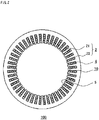
FIG. 1 is a schematic perspective view of a stator according to Embodiment 1 of the present invention. -
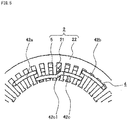
FIG. 2 is a schematic sectional view taken along the line A-A of the stator inFIG. 1 . -
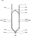
FIG. 3 discloses a schematic front view inFIG. 3(a) and a schematic perspective view inFIG. 3(b) of a unit coil according to Embodiment 1 of the present invention. -
FIG. 4 is a partial schematic view of a cross section along a direction perpendicular to the axial direction, of a stator core in which one unit coil is arranged, according to Embodiment 1 of the present invention. -
FIG. 5 is a partial schematic view of a terminal side end surface of the stator core in which one unit coil is arranged, according to Embodiment 1 of the present invention. -
FIG. 6 is a partial schematic view of an anti-terminal side end surface of the stator core in which one unit coil is arranged, according to Embodiment 1 of the present invention. -
FIG. 7 is a schematic front view of a conventional unit coil. -
FIG. 8 is a schematic perspective view of a stator intermediate in which unit coils of a comparative example are mounted to a stator core. -
FIG. 9 is a partial schematic end surface view of the stator intermediate inFIG. 8 as seen from a direction indicated by arrow F. -
FIG. 10 is a schematic perspective view showing the stator intermediate in which a first terminal wire and a second terminal wire to be joined with each other, of each unit coil of the comparative example, are opposed to each other in the radial direction. -
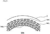
FIG. 11 is a partial schematic end surface view of the stator intermediate inFIG. 10 as seen from a direction indicated by arrow F. -
FIG. 12 is a partial schematic perspective view showing the stator intermediate in which the first terminal wire of each unit coil of the comparative example is brought to be gathered with the second terminal wire. -
FIG. 13 is a partial schematic end surface view of the stator intermediate inFIG. 12 as seen from a direction indicated by arrow F. -
FIG. 14 is a partial schematic perspective view showing the stator of the comparative example. -
FIG. 15 is a schematic view showing the unit coil according to Embodiment 1 of the present invention in the state in which the unit coil is not yet mounted to the stator core. -
FIG. 16 is a schematic perspective view of a stator intermediate to which the unit coils having the terminal wires that are not bent are mounted, according to Embodiment 1 of the present invention. -
FIG. 17 is a partial schematic end surface view of the stator intermediate inFIG. 16 as seen from a direction indicated by arrow F. -
FIG. 18 is a schematic perspective view showing the stator intermediate in which each first terminal wire and each second terminal wire to be joined with each other, of the unit coils, are opposed to each other in the radial direction, according to Embodiment 1 of the present invention. -
FIG. 19 is a partial schematic end surface view of the stator intermediate inFIG. 18 as seen from a direction indicated by arrow F. -
FIG. 20 is a partial schematic view showing a cross section along a direction perpendicular to the circumferential direction of the stator of the comparative example. -
FIG. 21 is a partial schematic view showing a cross section along a direction perpendicular to the circumferential direction of the stator according to Embodiment 1 of the present invention. -
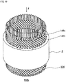
FIG. 22 is a schematic perspective view showing a stator intermediate in which a stator core is mounted to a coil basket, in a stator according toEmbodiment 2 of the present invention. -
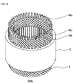
FIG. 23 is a schematic perspective view inFIG. 23(a) of a stator core component used for the stator according toEmbodiment 2 of the present invention, and a schematic view inFIG. 23(b) of the end surface of the stator core component in the axial direction. -
FIG. 24 is a schematic perspective view of the coil basket used for the stator according toEmbodiment 2 of the present invention. -
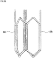
FIG. 25 is a schematic front view showing two unit coils used for producing the coil basket according to Embodiment 2 of the present invention. -
FIG. 26 is a schematic terminal-side top view illustrating the state in which an inserting-side unit coil is arranged with respect to a receiving-side unit coil in an overlapping manner in production of the coil basket according toEmbodiment 2 of the present invention. -
FIG. 27 is a schematic front view inFIG. 27(a) and a schematic terminal-side top view inFIG. 27(b) illustrating the state in which the inserting-side unit coil is arranged with respect to the receiving-side unit coil, in production of the coil basket according toEmbodiment 2 of the present invention. -
FIG. 28 is a schematic perspective view illustrating the state in which the stator core components are being attached to the coil basket according toEmbodiment 2 of the present invention. -
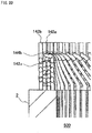
FIG. 29 is a schematic sectional view taken along B-B line of the coil basket inFIG. 28 . -
FIG. 30 is a schematic perspective view showing a stator intermediate in which a contracted coil basket is mounted to a stator core, in a stator according toEmbodiment 3 of the present invention. -
FIG. 31 is a schematic view of the end surface in the axial direction of the stator core used in the stator according toEmbodiment 3 of the present invention. -
FIG. 32 is a schematic view of the end surface in the axial direction, showing the state in which an inner core is arranged in a coil basket, according toEmbodiment 3 of the present invention. -
FIG. 33 is a schematic view of the end surface in the axial direction, showing the state in which the contracted coil basket is mounted to the inner core, according toEmbodiment 3 of the present invention. -
FIG. 34 is a schematic front view of a unit coil according toEmbodiment 4 of the present invention. -
FIG. 35 is a schematic side view of one unit coil forming a coil basket according toEmbodiment 4 of the present invention. -
FIG. 36 is a schematic perspective view of the coil basket used as a stator according toEmbodiment 4 of the present invention. -
FIG. 37 is a schematic sectional view showing the state in which an inner core is arranged in the coil basket according toEmbodiment 4 of the present invention. -
FIG. 38 is a schematic perspective view showing the inner core to which a contracted coil basket is mounted, according toEmbodiment 4 of the present invention. -
FIG. 39 is a schematic view showing a cross section along a direction perpendicular to the radial direction, of the inner core to which the contracted coil basket is mounted inFIG. 38 . -
FIG. 40 is a schematic front view showing each contracted unit coil forming the contracted coil basket according toEmbodiment 4 of the present invention. -
FIG. 41 is a schematic perspective view showing a stator intermediate according toEmbodiment 4 of the present invention. -
FIG. 42 is a schematic side view of one unit coil forming a coil basket according toEmbodiment 5 of the present invention. -
FIG. 43 is a schematic sectional view showing the state in which an inner core is arranged in the coil basket used for a stator according toEmbodiment 5 of the present invention. -
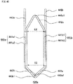
FIG. 44 is a schematic front view of a unit coil according to Embodiment 6 of the present invention. -
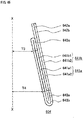
FIG. 45 is a schematic side view of one unit coil forming a coil basket according to Embodiment 6 of the present invention. -
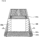
FIG. 46 is a schematic sectional view showing the state in which an inner core is inserted into the coil basket used for a stator according to Embodiment 6 of the present invention. -
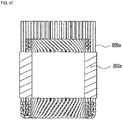
FIG. 47 is a schematic sectional view showing the inner core to which a contracted coil basket is mounted, according to Embodiment 6 of the present invention. -
FIG. 48 is a schematic front view showing each contracted unit coil forming the contracted coil basket according to Embodiment 6 of the present invention. -
FIG. 49 is a schematic side sectional view of a rotary electric machine according toEmbodiment 7 of the present invention. - Hereinafter, a stator, a rotary electric machine, and methods for manufacturing the stator and the rotary electric machine according to the present invention will be described with reference to the drawings.
- A circumferential direction, a radial direction, and an axial direction in the present invention refer to the circumferential direction, the radial direction, and the axial direction of the stator, respectively, unless otherwise specified.
-
FIG. 1 is a schematic perspective view of a stator according to Embodiment 1 of the present invention. -
FIG. 2 is a schematic sectional view taken along the line A-A of the stator inFIG. 1 . - As shown in
FIG. 1 andFIG. 2 , thestator 100 of the present embodiment comprises anannular stator core 2 and astator coil 10. - The
stator core 2 is formed of aback yoke 22 which is an outer circumferential part, andteeth 21 which protrude in the radial direction from the inner circumferential surface of theback yoke 22.Slots 5 are formed between therespective teeth 21. - The
stator coil 10 is formed of a plurality of unit coils 4 described later, and three phases of U phase, V phase and W phase are Y-connected. - The unit coils 4 are inserted in the
slots 5 and wound around theteeth 21. - Each
unit coil 4 is partially exposed from thestator core 2 in the axial direction. In thestator 100, the exposed part side where afirst terminal wire 42a and asecond terminal wire 42b of eachunit coil 4 are present is referred to as a terminal side, and the opposite side is referred to as a anti-terminal side. - In the present embodiment, the
stator core 2 having forty-eightslots 5 and forty-eightteeth 21 is shown as an example, but the numbers of theslots 5 and theteeth 21 are not limited thereto. -
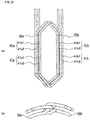
FIG. 3 is a schematic front view (a) and a schematic perspective view (b) of the unit coil according to Embodiment 1 of the present invention. -
FIG. 4 is a partial schematic view of a cross section along a direction perpendicular to the axial direction, of the stator core in which one unit coil is arranged, according to Embodiment 1 of the present invention. - The
unit coil 4 is formed by winding, substantially in a hexagonal shape, oneconductive wire 3 composed of a conductor portion and an insulation film coating the surface of the conductor portion. That is, thecoil unit 4 is formed in a concentric-winding manner. - As shown in
FIG. 4 , theunit coil 4 is arranged in twoslots 5 across a plurality ofteeth 21. That is, thestator coil 10 of the present embodiment is a distributed-winding coil. - The
unit coil 4 comprises: slot-accommodated portions to be respectively accommodated in the twoslots 5; coil end portions connecting the slot-accommodated portions; and terminal wires extending from the respective slot-accommodated portions. - In the present embodiment, in
FIG. 3 , the slot-accommodated portion positioned at the left on the drawing plane is referred to as a first slot-accommodatedportion 41a, and the other slot-accommodated portion positioned at the right on the drawing plane is referred to as a second slot-accommodatedportion 41b. - As shown in
FIG. 3 , the first slot-accommodatedportion 41a and the second slot-accommodatedportion 41b are each composed of two lines of theconductive wire 3. - That is, in
FIG. 3(a) , the first slot-accommodatedportion 41a is composed of a first slot-accommodated portion inner-side conductive wire 41a1 positioned on the inner side, and a first slot-accommodated portion outer-side conductive wire 41a2 positioned on the outer side. InFIG. 3(a) , the second slot-accommodatedportion 41b is composed of a second slot-accommodated portion inner-side conductive wire 41b1 positioned on the inner side, and a second slot-accommodated portion outer-side conductive wire 41b2 positioned on the outer side. - As shown in
FIG. 3(b) , the first slot-accommodated portion inner-side conductive wire 41a1 is positioned at a radially inner side of the first slot-accommodated portion outer-side conductive wire 41a2, and the second slot-accommodated portion inner-side conductive wire 41bl is positioned at a radially inner side of the second slot-accommodated portion outer-side conductive wire 41b2. - In the
stator core 2, theslot 5 in which the first slot-accommodatedportion 41a is provided and theslot 5 in which the second slot-accommodatedportion 41b is provided are located at positions separated from each other with a predetermined number of teeth therebetween in the radial direction. - In the present embodiment, the
slot 5 in which the second slot-accommodatedportion 41b of oneunit coil 4 is provided is located at a position separated from theslot 5 in which the first slot-accommodatedportion 41a of the oneunit coil 4 is provided, with a predetermined number of teeth therebetween in the clockwise circumferential direction. - As shown in
FIG. 4 , in the present embodiment, in thestator core 2 as seen from the terminal side, the first slot-accommodatedportion 41a is provided in theslot 5 at the left in the circumferential direction, and the second slot-accommodatedportion 41b is provided in theslot 5 at the right in the circumferential direction. - As shown in
FIG. 4 , in theslot 5 in which the first slot-accommodatedportion 41a is provided, the first slot-accommodated portion inner-side conductive wire 41a1 is located on the radially inner side and the first slot-accommodated portion outer-side conductive wire 41a2 is located on the radially outer side. - In the
slot 5 in which the second slot-accommodatedportion 41b is provided, the second slot-accommodated portion inner-side conductive wire 41bl is located on the radially inner side and the second slot-accommodated portion outer-side conductive wire 41b2 is located on the radially outer side. - As shown in
FIG. 4 , the positional relationship in the radial direction between the conductive wires in each slot-accommodated portion of theunit coil 4 is as follows. - In the radial direction, the position of the second slot-accommodated portion inner-side conductive wire 41b1 is shifted outward from the position of the first slot-accommodated portion inner-side conductive wire 41a1 by one line of the
conductive wire 3. - In radial direction, the position of the first slot-accommodated portion outer-side conductive wire 41a2 is shifted outward from the position of the second slot-accommodated portion inner-side conductive wire 41b1 by one line of the
conductive wire 3. - In the radial direction, the position of the second slot-accommodated portion outer-side conductive wire 41b2 is shifted outward from the position of the first slot-accommodated portion outer-side conductive wire 41a2 by one line of the
conductive wire 3. - In the radial direction, the position of the second slot-accommodated portion outer-side conductive wire 41b2 is shifted outward from the position of the first slot-accommodated portion inner-side conductive wire 41a1 by three lines of the
conductive wire 3. - A gap in which one line of the
conductive wire 3 can be inserted is present between the first slot-accommodated portion inner-side conductive wire 41a1 and the first slot-accommodated portion outer-side conductive wire 41a2, and between the first slot-accommodated portion outer-side conductive wire 41a2 and theback yoke 22. - Also, a gap in which one line of the
conductive wire 3 can be inserted is present between the second slot-accommodated portion inner-side conductive wire 41bl and the second slot-accommodated portion outer-side conductive wire 41b2. - As shown in
FIG. 3 , theunit coil 4 has afirst terminal wire 42a extending from the first slot-accommodated portion outer-side conductive wire 41a2, and asecond terminal wire 42b extending from the second slot-accommodated portion outer-side conductive wire 41b2. - On the terminal side where the
terminal wires - On the anti-terminal side, a coil end portion (referred to as a first anti-terminal-side coil end portion) 43a connecting the first slot-accommodated portion outer-side conductive wire 41a2 and the second slot-accommodated portion inner-side conductive wire 41b1, and a coil end portion (referred to as a second anti-terminal-side coil end portion) 43b connecting the first slot-accommodated portion inner-side conductive wire 41a1 and the second slot-accommodated portion outer-side conductive wire 41b2, are provided.
-
FIG. 5 is a partial schematic view of the terminal-side end surface of the stator core in which one unit coil is arranged, according to Embodiment 1 of the present invention. -
FIG. 6 is a partial schematic view of the anti-terminal-side end surface of the stator core in which one unit coil is arranged, according to Embodiment 1 of the present invention. - As shown in
FIG. 5 , the terminal-sidecoil end portion 42c has a lane change portion 42c1 for adjusting the shifting of the second slot-accommodated portion inner-side conductive wire 41b1 radially outward from the first slot-accommodated portion inner-side conductive wire 41a1 by one line of theconductive wire 3. That is, the lane change portion 42c1 crosses the width of one line of theconductive wire 3 in the radial direction. - As shown in
FIG. 6 , the first anti-terminal-sidecoil end portion 43a has a lane change portion 43a1 for adjusting the shifting of the first slot-accommodated portion outer-side conductive wire 41a2 radially outward from the second slot-accommodated portion inner-side conductive wire 41b1 by one line of theconductive wire 3. That is, the lane change portion 43a1 crosses the width of one line of theconductive wire 3 in the radial direction. - In addition, the second anti-terminal-side
coil end portion 43b has a lane change portion 43b1 for adjusting the shifting of the second slot-accommodated portion outer-side conductive wire 41b2 radially outward from the first slot-accommodated portion inner-side conductive wire 41a1 by three lines of theconductive wire 3. That is, the lane change portion 43b1 crosses the width of three lines of theconductive wire 3 in the radial direction. - The second anti-terminal-side
coil end portion 43b is located axially outward with respect to the first anti-terminal-sidecoil end portion 43a, and crosses the first anti-terminal-sidecoil end portion 43a. - The
second terminal wire 42b extends from the second slot-accommodated portion outer-side conductive wire 41b2 positioned on the radially outermost side, and thefirst terminal wire 42a extends from the first slot-accommodated portion outer-side conductive wire 41a2 at a position shifted inward from the radially outermost side by one line of theconductive wire 3. - In the present embodiment, the
first terminal wire 42a extends from the first slot-accommodated portion outer-side conductive wire 41a2, thesecond terminal wire 42b extends from the second slot-accommodated portion outer-side conductive wire 41b2, and the terminal-sidecoil end portion 42c connects the first slot-accommodated portion inner-side conductive wire 41a1 and the second slot-accommodated portion inner-side conductive wire 41b1. - However, the
first terminal wire 42a may extend from the first slot-accommodated portion inner-side conductive wire 41a1, thesecond terminal wire 42b may extend from the second slot-accommodated portion inner-side conductive wire 41b1, and the terminal-sidecoil end portion 42c may connect the first slot-accommodated portion outer-side conductive wire 41a2 and the second slot-accommodated portion outer-side conductive wire 41b2. - In the present embodiment, in the
unit coil 4, the first slot-accommodatedportion 41a and the second slot-accommodatedportion 41b are each formed of two lines of theconductive wire 3. However, the number of lines of the conductive wire forming each slot-accommodated portion may be n within a range that allows formation of the stator coil. Here, n is an integer not less than 2. - In this case, the unit coil has (n - 1) number of terminal-side coil end portions, (n - 1) number of first anti-terminal-side coil end portions, and one second anti-terminal-side coil end portion.
- The terminal-side coil end portions and the first anti-terminal-side coil end portions each have a lane change portion crossing the width of one line of the conductive wire. That is, the terminal-side coil end portions and the first anti-terminal-side coil end portions each connect the first slot-accommodated portion conductive wire and the second slot-accommodated portion conductive wire that are shifted from each other by one line of the conductive wire in the radial direction.
- The second anti-terminal-side coil end portion has a lane change portion crossing the width of (2n - 1) lines of the conductive wire. That is, the second anti-terminal-side coil end portion connects the first slot-accommodated portion conductive wire and the second slot-accommodated portion conductive wire that are shifted from each other by (2n - 1) lines of the conductive wire in the radial direction.
- The second anti-terminal-side coil end portion is located axially outward with respect to the first anti-terminal-side coil end portions, and crosses (n - 1) number of the first anti-terminal-side
coil end portions 43a. - The second terminal wire extends from the second slot-accommodated portion conductive wire positioned on the radially outermost side, and the first terminal wire extends from the first slot-accommodated portion conductive wire at a position shifted inward by one line of the
conductive wire 3 in the radial direction from the second slot-accommodated portion conductive wire positioned on the radially outermost side. - However, the first terminal wire may extend from the first slot-accommodated portion conductive wire positioned on the radially innermost side, and the second terminal wire may extend from the second slot-accommodated portion conductive wire at a position shifted outward by one line of the
conductive wire 3 in the radial direction from the first slot-accommodated portion conductive wire positioned on the radially innermost side. - The conductive wires extending from the terminal wires are not connected in the terminal-side coil end portion.
- The first terminal wire and the second terminal wire are shifted from each other by one line of the conductive wire in the radial direction.
- Next, as a comparative example, a conventional unit coil disclosed in Patent Document 1 will be described.
-
FIG. 7 is a schematic front view of the conventional unit coil. - As shown in
FIG. 7 , theconventional unit coil 104 is also formed by winding one conductive wire in a lap winding manner, and comprises a first slot-accommodatedportion 141a, a second slot-accommodatedportion 141b, a coil end portion connecting the slot-accommodated portions, and terminal wires extending from the respective slot-accommodated portions. - The first slot-accommodated
portion 141a is formed by two conductive wires comprising a first slot-accommodated portion inner-side conductive wire 141a1 on the near side on the drawing plane inFIG. 7 , and a first slot-accommodated portion outer-side conductive wire 141a2 on the far side on the drawing plane inFIG. 7 . - The second slot-accommodated
portion 141b is formed by two conductive wires comprising a second slot-accommodated portion inner-side conductive wire 141b1 on the near side on the drawing plane inFIG. 7 , and a second slot-accommodated portion outer-side conductive wire 141b2 on the far side on the drawing plane inFIG. 7 . - As coil end portions, there are a first anti-terminal-side
coil end portion 143a connecting the first slot-accommodated portion inner-side conductive wire 141a1 and the second slot-accommodated portion inner-side conductive wire 141b1, a terminal-sidecoil end portion 142c connecting the second slot-accommodated portion inner-side conductive wire 141b1 and the first slot-accommodated portion outer-side conductive wire 141a2, and a second anti-terminal-sidecoil end portion 143b connecting the first slot-accommodated portion outer-side conductive wire 141a2 and the second slot-accommodated portion outer-side conductive wire 141b2. - The terminal-side
coil end portion 142c has a lane change portion 142c1 crossing the width of one line of theconductive wire 3 in the radial direction. The first anti-terminal-sidecoil end portion 143a has a lane change portion 143a1 crossing the width of one line of theconductive wire 3 in the radial direction. The second anti-terminal-sidecoil end portion 143b has a lane change portion 143b1 crossing the width of one line of theconductive wire 3 in the radial direction. - In the radial direction, the position of the second slot-accommodated portion outer-side conductive wire 141b2 is shifted outward from the position of the first slot-accommodated portion inner-side conductive wire 141a1 by three lines of the
conductive wire 3. - As terminal wires, there are a
first terminal wire 142a extending from the first slot-accommodated portion inner-side conductive wire 141a1, and asecond terminal wire 142b extending from the second slot-accommodated portion outer-side conductive wire 141b2. That is, in the radial direction, the position of thefirst terminal wire 142a and the position of thesecond terminal wire 142b are shifted from each other by three lines of theconductive wire 3. -
FIG. 8 is a schematic perspective view of a stator intermediate in which the unit coil of the comparative example is mounted to the stator core. -
FIG. 9 is a partial schematic end surface view of the stator intermediate inFIG. 8 as seen from a direction indicated by arrow F. - In the stator intermediate shown in
FIG. 8 andFIG. 9 , each terminal wire is not joined with a terminal wire of another unit coil. - In a
stator 500 of the comparative example described later, thefirst terminal wire 142a of oneunit coil 104 is joined with thesecond terminal wire 142b of theunit coil 104 separated from thefirst terminal wire 142a with, for example, five slots therebetween in the counterclockwise circumferential direction, and thesecond terminal wire 142b is joined with thefirst terminal wire 142a of theunit coil 104 separated from thesecond terminal wire 142b with, for example, five slots therebetween in the clockwise circumferential direction. - In the stator intermediate 500a shown in
FIG. 8 andFIG. 9 , thefirst terminal wire 142a of eachunit coil 104 and thesecond terminal wire 142b of anotherunit coil 104 to be joined with thefirst terminal wire 142a are not located at the positions opposing to each other in the radial direction. - Accordingly, in order to join the
first terminal wire 142a of eachunit coil 104 and thesecond terminal wire 142b of anotherunit coil 104, first, thefirst terminal wire 142a of theunit coil 104 is bent in the counterclockwise direction indicated by arrow L inFIG. 9 . At this time, the bentfirst terminal wire 142a is formed into an arc shape substantially parallel with the inner circumferential surface of thestator core 2. - The inner circumferential surface of the
stator core 2 is a surface opposing to the outer circumferential surface of a rotor to be provided when the rotary electric machine is formed. - In addition, the
second terminal wire 142b of theunit coil 104 is bent in the clockwise direction indicated by arrow R inFIG. 9 . At this time, the bentsecond terminal wire 142b is formed into an arc shape substantially parallel with the inner circumferential surface of thestator core 2. - The bending of the first
terminal wires 142a and the bending of the secondterminal wires 142b are performed at the same time for all the unit coils 104. -
FIG. 10 is a schematic perspective view showing the stator intermediate in which each first terminal wire and each second terminal wire to be joined with each other, of the unit coils of the comparative example, are opposed to each other in the radial direction. -
FIG. 11 is a partial schematic end surface view of the stator intermediate inFIG. 10 as seen from a direction indicated by arrow F. - In the stator intermediate 500b shown in
FIG. 10 andFIG. 11 , thefirst terminal wire 142a of eachunit coil 104 and thesecond terminal wire 142b of anotherunit coil 104 are located at the positions opposing to each other in the radial direction. - However, each
first terminal wire 142a is located away in the radial direction from thesecond terminal wire 142b of anotherunit coil 104. Therefore, in order to join thefirst terminal wire 142a and thesecond terminal wire 142b, at least one terminal wire of thefirst terminal wire 142a and thesecond terminal wire 142b needs to be bent in the radial direction so that the terminal wires are gathered. -
FIG. 12 is a partial schematic perspective view showing the stator intermediate in which the first terminal wire of each unit coil of the comparative example is brought to be gathered with the second terminal wire. -
FIG. 13 is a partial schematic end surface view of the stator intermediate inFIG. 12 as seen from a direction indicated by arrow F. -
FIG. 14 is a partial schematic perspective view showing the stator of the comparative example. - In the stator intermediate 500c in which the
first terminal wire 142a of each unit coil of the comparative example is brought to be gathered with thesecond terminal wire 142b as shown inFIG. 12 andFIG. 13 , gatheredportions 144a are joined by welding, and thestator 500 of the comparative example as shown inFIG. 14 is obtained. - In
FIG. 14 , weldedportions 144c are top portions of thefirst terminal wire 142a and thesecond terminal wire 142b. However, without limitation thereto, the weldedportions 144c may be any parts of the gatheredportions 144a. - In the stator coil of the
stator 500 of the comparative example, at least one terminal wire of thefirst terminal wire 142a and thesecond terminal wire 142b crosses over the terminal-side coil end portion. That is, the stator coil has a crossingportion 144b. - Next, mounting of the unit coil and connection of the terminal wires in the
stator 100 of the present embodiment will be described. -
FIG. 15 is a schematic view showing the unit coil according to Embodiment 1 of the present invention in the state in which the unit coil is not yet mounted to the stator core. - First, the
unit coil 4 having thefirst terminal wire 42a extending from the first slot-accommodated portion outer-side conductive wire 41a2 without being bent, and thesecond terminal wire 42b extending from the second slot-accommodated portion outer-side conductive wire 41b2 without being bent as shown inFIG. 15 is mounted to thestator core 2. -
FIG. 16 is a schematic perspective view of a stator intermediate to which the unit coils having the terminal wires that are not bent are mounted, according to Embodiment 1 of the present invention. -
FIG. 17 is a partial schematic end surface view of the stator intermediate inFIG. 16 as seen from a direction indicated by arrow F. - As shown in
FIG. 16 , a plurality of the unit coils 4 are mounted to thestator core 2. At this time, between the conductive wires of the slot-accommodated portion of eachunit coil 4, conductive wires of the slot-accommodated portion of anotherunit coil 4 are inserted. -
FIG. 16 andFIG. 17 show the state in which each terminal wire is not joined with the terminal wire of another unit coil. - Also in the
stator 100 of the present embodiment, thefirst terminal wire 42a of oneunit coil 4 is joined with thesecond terminal wire 42b of anotherunit coil 4 separated from thefirst terminal wire 42a with, for example, five slots therebetween in the counterclockwise circumferential direction, and thesecond terminal wire 42b of oneunit coil 4 is joined with thefirst terminal wire 42a of anotherunit coil 4 separated from thesecond terminal wire 42b with, for example, five slots therebetween in the clockwise circumferential direction. - In the stator intermediate 100a to which the unit coils 4 are mounted as shown in
FIG. 16 , thefirst terminal wire 42a of eachunit coil 4 and thesecond terminal wire 42b of anotherunit coil 4 to be joined with thefirst terminal wire 42a are not located at positions opposing to each other in the radial direction. - Accordingly, in order to join the
first terminal wire 42a of eachunit coil 4 and thesecond terminal wire 42b of anotherunit coil 4, first, thefirst terminal wire 42a of theunit coil 4 is bent in the counterclockwise direction indicated by arrow L as shown inFIG. 17 . At this time, the bentfirst terminal wire 42a is formed into an arc shape substantially parallel with the inner circumferential surface of thestator core 2. - In addition, the
second terminal wire 42b of theunit coil 4 is bent in the clockwise direction indicated by arrow R as shown inFIG. 17 . At this time, the bentsecond terminal wire 42b is formed into an arc shape substantially parallel with the inner circumferential surface of thestator core 2. - The bending of the first
terminal wires 42a and the bending of the secondterminal wires 42b are performed at the same time for all the unit coils 4. -
FIG. 18 is a schematic perspective view showing the stator intermediate in which each first terminal wire and each second terminal wire to be joined with each other, of the unit coils, are opposed to each other in the radial direction, according to Embodiment 1 of the present invention. -
FIG. 19 is a partial schematic end surface view of the stator intermediate inFIG. 18 as seen from a direction indicated by arrow F. - In the stator intermediate 100b shown in
FIG. 18 andFIG. 19 , thefirst terminal wire 42a of eachunit coil 4 and thesecond terminal wire 42b of anotherunit coil 4 to be joined with thefirst terminal wire 42a are located at the positions opposing to each other in the radial direction. - In addition, the
first terminal wire 42a of eachunit coil 4 and thesecond terminal wire 42b of anotherunit coil 4 to be joined with thefirst terminal wire 42a are in contact with each other in the radial direction. - In the
first terminal wire 42a of eachunit coil 4 and thesecond terminal wire 42b of anotherunit coil 4, portions (referred to as contact portions) 44a that are opposed to each other and in contact with each other are joined by welding, and thestator 100 of the present embodiment is obtained. - As shown in
FIG. 1 , in thestator 100 of the present embodiment, weldedportions 44c are top portions of thefirst terminal wire 42a and thesecond terminal wire 42b. However, without limitation thereto, the weldedportions 44c may be any parts of thecontact portions 44a of thefirst terminal wire 42a and thesecond terminal wire 42b. - In the
stator 100 of the present embodiment, it is not necessary to bend, in the radial direction, at least one terminal wire of thefirst terminal wire 42a and thesecond terminal wire 42b to gather the terminal wires. Therefore, the number of times for bending theconductive wire 3 forming the coil is decreased and the number of processes in manufacturing of the stator is decreased, whereby the productivity is improved. - In addition, since the number of times for bending the
conductive wire 3 is decreased, the frequency at which the insulation film of theconductive wire 3 is impaired can be reduced and the coil is less damaged. Thus, the insulation reliability of the stator is enhanced. -
FIG. 20 is a partial schematic view showing a cross section along a direction perpendicular to the circumferential direction of the stator of the comparative example. -
FIG. 21 is a partial schematic view showing a cross section along a direction perpendicular to the circumferential direction of the stator according to Embodiment 1 of the present invention. -
FIG. 20 andFIG. 21 both show the terminal side of the stator. - As shown in
FIG. 20 , in thestator 500 of the comparative example, thefirst terminal wire 142a is bent to be gathered with thesecond terminal wire 142b, whereby the crossingportion 144b is formed. - That is, because of presence of the crossing
portion 144b, it is impossible to provide a cover for protecting the terminal-sidecoil end portion 142c during welding. - Therefore, there is a possibility that, when the
first terminal wire 142a and thesecond terminal wire 142b are joined by welding, sputter adheres to the terminal-sidecoil end portion 142c, as a result, the insulation quality of the coil deteriorates. - However, as shown in
FIG. 21 , in thestator 100 of the present embodiment, since there is no crossing portion, welding can be performed with the terminal-sidecoil end portion 42c covered with acover 8. Therefore it is possible to prevent sputter from adhering to the terminal-sidecoil end portion 42c. - That is, it is possible to prevent the insulation quality of the coil from being deteriorated by sputter in welding, and thus the reliability is enhanced.
- In addition, since there is no crossing portion in the stator of the present embodiment, the height of the coil end can be reduced by an amount corresponding to the crossing portion.
- In the present embodiment, a round wire is used as the conductive wire. However, instead of the round wire, a rectangular wire may be used.
- In the present embodiment, the
slot 5 in which the second slot-accommodatedportion 41b is provided is located at a position separated from theslot 5 in which the first slot-accommodatedportion 41a is provided, with a predetermined number of teeth therebetween in the clockwise circumferential direction. However, theslot 5 in which the second slot-accommodatedportion 41b is provided may be located at a position separated from theslot 5 in which the first slot-accommodatedportion 41a is provided, with a predetermined number of teeth therebetween in the counterclockwise circumferential direction. - That is, in the stator core, the first slot-accommodated
portion 41a is accommodated in theslot 5 at one of positions separated from each other with a predetermined number of teeth therebetween in the circumferential direction, and the second slot-accommodatedportion 41b is accommodated in theslot 5 at the other position. - A stator according to
Embodiment 2 of the present invention comprises stator coils formed as a coil basket, and a stator core mounted to the stator coils. A unit coil used in the present embodiment has the same shape as theunit coil 4 of Embodiment 1, and is formed by winding one conductive wire. -
FIG. 22 is a schematic perspective view showing a stator intermediate in which the stator core is mounted to the coil basket, in the stator according toEmbodiment 2 of the present invention. - In the stator intermediate 200a shown in
FIG. 22 in which thestator core 202 is mounted to thecoil basket 206, eachfirst terminal wire 42a and eachsecond terminal wire 42b have not been bent in the circumferential direction yet and have not been joined by welding or the like yet. - As shown in
FIG. 22 , thestator core 202 is formed by connectingstator core components 202a in the circumferential direction and arranging them in an annular shape. -
FIG. 23 is a schematic perspective view (a) of the stator core component used for the stator according toEmbodiment 2 of the present invention, and a schematic view (b) of the end surface of the stator core component in the axial direction. - As shown in
FIG. 23 , thestator core component 202a of the present embodiment comprises a backyoke forming portion 222a, and twoteeth 221 protruding from an innercircumferential surface 222c of the backyoke forming portion 222a. The side surface at the tip end of eachtooth 221 is provided with no protruding portion such as a tip end shoe, and the side surfaces in the circumferential direction of eachtooth 221 are flat. - The gap between the two
teeth 221 is aslot 205. - An end surface (referred to as a tooth circumferential-direction outer-side end surface) 221b on the outer side in the circumferential direction of each
tooth 221 is positioned on the inner side in the circumferential direction relative to an end surface (referred to as a back yoke forming portion circumferential-direction end surface) 222b in the circumferential direction of the backyoke forming portion 222a. - The
stator core components 202a are joined with each other by causing their back yoke forming portion circumferential-direction end surfaces 222b to come in contact with each other. In thestator core 202 arranging thestator core components 202a in an annular shape,slots 205 are formed also between the tooth circumferential-direction outer-side end surfaces 221b opposing to each other of theteeth 221 of the adjacentstator core components 202a. -
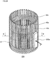
FIG. 24 is a schematic perspective view of the coil basket used for the stator according toEmbodiment 2 of the present invention. - As shown in
FIG. 24 , thecoil basket 206 of the present embodiment is formed by arranging a plurality of the unit coils 4 in the circumferential direction. - As described in detail later, the
coil basket 206 is formed by inserting, between the conductive wires of the slot-accommodated portion of oneunit coil 4, a conductive wire of the slot-accommodated portion of anotherunit coil 4 adjacent thereto, and by arranging the plurality of unit coils 4 in an annular shape. - Next, a method for manufacturing the
coil basket 206 will be described. -
FIG. 25 is a schematic front view showing two unit coils used for producing the coil basket according toEmbodiment 2 of the present invention. - In
FIG. 25 , in production of thecoil basket 206, a unit coil (referred to as an inserting-side unit coil) 45 a of which a conductive wire of the slot-accommodated portion is to be inserted is shown at the left on the drawing plane, and a unit coil (referred to as a receiving-side unit coil) 45b in which the conductive wire is to be inserted between the conductive wires of the slot-accommodated portion is shown at the right on the drawing plane. -
FIG. 26 is a schematic terminal-side top view illustrating the state in which the inserting-side unit coil is arranged with respect to the receiving-side unit coil in an overlapping manner in production of the coil basket according toEmbodiment 2 of the present invention. - As shown in
FIG. 26 , the second slot-accommodated portion inner-side conductive wire 41b1 of the inserting-side unit coil 45a is moved while being turned in a direction indicated by arrow S, to pass between the first slot-accommodated portion inner-side conductive wire 41a1 and the first slot-accommodated portion outer-side conductive wire 41a2 of the receiving-side unit coil 45b, and the inserting-side unit coil 45a is arranged. - At the same time, the second slot-accommodated portion outer-side conductive wire 41b2 of the inserting-
side unit coil 45a is moved while being turned in a direction indicated by arrow S, to pass by the radially outer side of the first slot-accommodated portion outer-side conductive wire 41a2 of the receiving-side unit coil 45b, and the inserting-side unit coil 45a is arranged. - That is, the inserting-
side unit coil 45a and the receiving-side unit coil 45b are arranged to overlap each other so as to be shifted from each other in the circumferential direction. -
FIG. 27 is a schematic front view (a) and a schematic terminal-side top view (b) illustrating the state in which the inserting-side unit coil is arranged with respect to the receiving-side unit coil, in production of the coil basket according toEmbodiment 2 of the present invention. - As shown in
FIG. 27 , in the inserting-side unit coil 45a and the receiving-side unit coil 45b that overlap each other, the first slot-accommodatedportion 41a of the inserting-side unit coil 45a is shifted from the first slot-accommodatedportion 41a of the receiving-side unit coil 45b by oneslot 205 in the counterclockwise circumferential direction, and the second slot-accommodatedportion 41b of the inserting-side unit coil 45a is shifted from the second slot-accommodatedportion 41b of the receiving-side unit coil 45b by oneslot 205 in the counterclockwise circumferential direction. - Thus, the
coil basket 206 is formed by arranging the unit coils in an annular shape while overlapping each other in a shifted manner. - In the present embodiment, since the number of the slots is 48, the shift amount corresponding to one slot is such that the angle between two sides connecting the center in the same positions of the unit coil and the overlapping unit coil is 7.5°.
- Naturally, if the number of the slots differs, the shift amount corresponding to one slot also differs, thus the number of the slots is not limited to 7.5°.
- Next, the method for attaching the
stator core components 202a to thecoil basket 206 to manufacture the stator will be described. -
FIG. 28 is a schematic perspective view illustrating the state in which the stator core components are attached to the coil basket according toEmbodiment 2 of the present invention. -
FIG. 29 is a schematic sectional view taken along B-B line of the coil basket inFIG. 28 . - As shown in
FIG. 28 andFIG. 29 , in attachment of thestator core components 202a to thecoil basket 206, first, theteeth 221 of thestator core components 202a are inserted between the slot-accommodated portions of a plurality of unit coils 4 forming thecoil basket 206. The insertion of theteeth 221 into thecoil basket 206 is performed by pressing thestator core components 202a in a direction indicated by arrow P from the outer circumferential side of thecoil basket 206 to move thestator core components 202a inwardly in the radial direction. - Next, in the same way, all the
stator core components 202a are attached to thecoil basket 206, and the stator intermediate 200a shown inFIG. 22 is produced. - In the stator intermediate 200a, all the slot-accommodated portions are accommodated in the
slots 205. - The
stator core components 202a attached to thecoil basket 206 and arranged in an annular shape with their back yoke forming portion circumferential-direction end surfaces 222b being in contact with each other are integrated by joining the backyoke forming portions 222a by welding or the like. The integrated part of the backyoke forming portions 222a becomes a back yoke of thestator core 202, whereby thestator core 202 is formed. - Next, as in Embodiment 1, the
first terminal wire 42a and thesecond terminal wire 42b of eachunit coil 4 are bent. Then, thefirst terminal wire 42a of eachunit coil 4 and thesecond terminal wire 42b of anotherunit coil 4 are opposed to each other in the radial direction and come in contact with each other. - Next, the
first terminal wire 42a of eachunit coil 4 and thesecond terminal wire 42b of anotherunit coil 4 which are opposed to each other and in contact with each other are joined by welding or the like to complete the stator coil, whereby the stator is manufactured. - Also in the stator of the present embodiment, since the
first terminal wire 42a and thesecond terminal wire 42b of eachunit coil 4 are arranged so as to be shifted from each other by one line of the conductive wire in the radial direction, it is possible to cause thefirst terminal wire 42a of eachunit coil 4 and thesecond terminal wire 42b of anotherunit coil 4 to be opposing to each other in the radial direction and to be in contact with each other, without providing a crossing portion. Thus, the same effect as in the stator of Embodiment 1 is provided. - In addition, since the stator is manufactured by inserting the
stator core components 202a into thecoil basket 206 from the outer circumferential side in the radial direction, the stator core can be easily attached to the stator coil and thus the productivity is improved. - In addition, a load applied to the stator coil is small when the
stator core components 202a are inserted into thecoil basket 206, thus deterioration in the insulation property of the unit coils 4 can be prevented. - In the present embodiment, each stator core component has two teeth, but the number of the teeth is not limited to two.
- A stator according to
Embodiment 3 of the present invention comprises stator coils and a stator core to which the stator coils are mounted. - A unit coil used in the present embodiment has the same shape as the
unit coil 4 of Embodiment 1, and is formed by winding one conductive wire. - A coil basket forming the stator coils is the same as the
coil basket 206 ofEmbodiment 2. -
FIG. 30 is a schematic perspective view showing a stator intermediate in which a contracted coil basket is mounted to the stator core, in the stator according toEmbodiment 3 of the present invention. - In the stator intermediate 300a shown in
FIG. 30 in which the contractedcoil basket 306a is mounted to thestator core 302, eachfirst terminal wire 342a and eachsecond terminal wire 342b have not been bent in the circumferential direction yet and have not been joined by welding or the like yet. - The
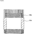
stator core 302 shown inFIG. 30 is formed into aninner core 302a located on the radially inner side, and anouter core 302b separate from theinner core 302a and located on the radially outer side. Theouter core 302b is a back yoke of thestator core 302. -
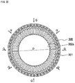
FIG. 31 is a schematic view of the end surface in the axial direction of the stator core used in the stator according toEmbodiment 3 of the present invention. - As shown in
FIG. 31 , theinner core 302a is formed by a plurality ofteeth 321 and a plurality ofconnection portions 321a. - The plurality of
teeth 321 are radially arranged at regular intervals along the circumferential direction. Eachconnection portion 321a connects the radially-inner-side ends of theadjacent teeth 321. The radially-inner-side ends of the plurality ofteeth 321 and the plurality ofconnection portions 321a form an annular body. -
Slots 305 are formed between theadjacent teeth 321. - The
outer core 302b serving as a back yoke of thestator core 302 has a cylindrical shape. The inner circumferential surface of theouter core 302b fixes the radially-outer-side ends of theteeth 321 of theinner core 302a. - The method for manufacturing the stator of the present embodiment will be described.
-
FIG. 32 is a schematic view of the end surface in the axial direction, showing the state in which the inner core is arranged in the coil basket, according toEmbodiment 3 of the present invention. - First, the
coil basket 306 is produced by the same operation as inEmbodiment 2. - However, in each unit coil to be used, the width in the circumferential direction of the terminal-side coil end portion and the width in the circumferential direction of the anti-terminal-side coil end portion are increased, and the inner diameter of the
coil basket 306 is greater than the outer diameter D of theinner core 302a. - Next, as shown in
FIG. 32 , theinner core 302a is arranged on the inner circumferential side of thecoil basket 306. - Next, as shown in
FIG. 32 , thecoil basket 306 is tightened from the outer circumferential part indicated by arrows Q, whereby the bending angles of the coil end portions on the terminal side and the anti-terminal side in each unit coil are decreased and the unit coil becomes a contracted unit coil in which the widths in the circumferential direction of the coil end portions are reduced. - That is, while the
coil basket 306 is contracted to reduce its inner diameter, theteeth 321 are inserted between the slot-accommodated portions of the unit coils, whereby the coil basket (referred to as a contracted coil basket) 306a that has been contracted is mounted to theinner core 302a. -
FIG. 33 is a schematic view of the end surface in the axial direction, showing the state in which the contracted coil basket is mounted to the inner core, according toEmbodiment 3 of the present invention. - When the contracted
coil basket 306a is mounted to theinner core 302a, all the slot-accommodated portions are accommodated in theslots 305. - Next, the
inner core 302a to which the contractedcoil basket 306a is mounted is pressed into theouter core 302b, and the stator intermediate 300a shown inFIG. 30 is produced. - Next, as in Embodiment 1, the
first terminal wire 342a and thesecond terminal wire 342b of each contracted unit coil are bent. Then, thefirst terminal wire 342a of each contracted unit coil and thesecond terminal wire 342b of another contracted unit coil to be joined with thefirst terminal wire 342a are opposed to each other in the radial direction and are in contact with each other. - Next, the
first terminal wire 342a of each contracted unit coil and thesecond terminal wire 342b of another contracted unit coil which are opposed to each other and are in contact with each other are joined by welding or the like to complete the stator coil, whereby the stator is manufactured. - In the stator of the present embodiment, since the
first terminal wire 342a and thesecond terminal wire 342b of each arranged unit coil are arranged so as to be shifted from each other by one line of the conductive wire in the radial direction, it is possible to cause thefirst terminal wire 342a of each arranged unit coil and thesecond terminal wire 342b of another arranged unit coil to be opposed to each other in the radial direction and to be in contact with each other, without providing a crossing portion. Thus, the same effect as in the stator of Embodiment 1 is provided. - In addition, in the
stator core 302 used as the stator of the present embodiment, since the radially-inner-side ends of theteeth 321 are connected by theconnection portions 321a, the accuracy of the shape of the inner circumference of the stator core is enhanced. Therefore, in the rotary electric machine using the stator of the present embodiment, cogging torque and torque ripple are reduced. - A stator according to
Embodiment 4 of the present invention also comprises stator coils and a stator core to which the stator coils are mounted. The stator core used in the present embodiment is the same as thestator core 302 ofEmbodiment 3. - However, the shape of the unit coil and the shape of the coil basket are different from those in
Embodiment 3. However, in the unit coil, the number of lines of the conductive wire in each slot-accommodated portion, the number of the coil end portions, and the width which the lane change portion crosses are the same as those inEmbodiment 3. - Each unit coil is formed by winding one conductive wire.
-
FIG. 34 is a schematic front view of the unit coil according toEmbodiment 4 of the present invention. - As shown in
FIG. 34 , in theunit coil 404 of the present embodiment, a width (referred to as the width of the terminal-side coil end portion) E1 in the circumferential direction of a terminal-sidecoil end portion 442c is greater than a width (referred to as the width of the anti-terminal-side coil end portion) E2 in the circumferential direction of a first anti-terminal-sidecoil end portion 443a and a second anti-terminal-sidecoil end portion 443b. - In the
unit coil 404 of the present embodiment, the terminal-sidecoil end portion 442c has a lane change portion 442c1, the first anti-terminal-sidecoil end portion 443a has a lane change portion 443a1, and the second anti-terminal-sidecoil end portion 443b has a lane change portion 443b1. - A first slot-accommodated
portion 441a is composed of a first slot-accommodated portion inner-side conductive wire 441a1 and a first slot-accommodated portion outer-side conductive wire 441a2. - A second slot-accommodated
portion 441b is composed of a second slot-accommodated portion inner-side conductive wire 441b1 and a second slot-accommodated portion outer-side conductive wire 441b2. -
FIG. 35 is a schematic side view of one unit coil forming the coil basket according toEmbodiment 4 of the present invention. - As shown in
FIG. 35 , in theunit coil 404, first and secondterminal wires coil end portion 442c are bent, inward in the radial direction of the coil basket as indicated by arrow M, with respect to the extended line from the first and second slot-accommodatedportions - In addition, first and second anti-terminal-side
coil end portions portions - In each
unit coil 404 forming thecoil basket 406 described later, a distance T1 between the central axis X of thecoil basket 406 and the terminal-side end of the slot-accommodated portion is greater than a distance T2 between the central axis X of thecoil basket 406 and the anti-terminal-side end of the slot-accommodated portion. - That is, in each
unit coil 404 forming thecoil basket 406 of the present embodiment, the slot-accommodatedportions - A method for manufacturing the stator of the present embodiment will be described.
- The
coil basket 406 of the present embodiment is produced by the same method as in thecoil basket 206 ofEmbodiment 2. - That is, the conductive wire of the second slot-accommodated
portion 441b of the inserting-side unit coil 404 passes between the conductive wires of the first slot-accommodatedportion 441a of the receiving-side unit coil 404, thereby the unit coils 404 are overlapped each other so as to be shifted from each other in the circumferential direction. Then, all the unit coils 404 are overlapped each other so as to be shifted from each other in the circumferential direction and are arranged in an annular shape, whereby thecoil basket 406 is produced. -
FIG. 36 is a schematic perspective view of the coil basket used as the stator according toEmbodiment 4 of the present invention. - As shown in
FIG. 36 , the inner diameter on the terminal side of thecoil basket 406 of the present embodiment is greater than the inner diameter on the anti-terminal side. - In addition, the inner diameter on the terminal side of the
coil basket 406 is greater than the outer diameter D of theinner core 302a shown inFIG. 32 . The inner diameter on the anti-terminal side of thecoil basket 406 is greater than a diameter (referred to as an inter-slot diameter) G between the bottoms of theslots 305 opposed to each other in theinner core 302a shown inFIG. 31 . Preferably, the difference between the inner diameter on the terminal side of thecoil basket 406 and the outer diameter D of theinner core 302a, and the difference between the inner diameter on the anti-terminal side of thecoil basket 406 and the inter-slot diameter G, are small. - Next, the
coil basket 406 is mounted to theinner core 302a. -
FIG. 37 is a schematic sectional view showing the state in which the inner core is arranged in the coil basket according toEmbodiment 4 of the present invention. -
FIG. 38 is a schematic perspective view showing the inner core to which the contracted coil basket is mounted, according toEmbodiment 4 of the present invention. -
FIG. 39 is a schematic view showing a cross section along a direction perpendicular to the radial direction, of the inner core to which the contracted coil basket is mounted inFIG. 38 . - In mounting of the
coil basket 406 to theinner core 302a, first, theinner core 302a is inserted from the terminal side of thecoil basket 406. Then, as shown inFIG. 37 , a force is applied to thecoil basket 406 from the outer circumferential side as indicated by arrows Q. - At this time, the
teeth 321 of theinner core 302a are inserted into the gaps between the slot-accommodated portions of thecoil basket 406, and thecoil basket 406 is contracted, whereby all the slot-accommodated portions are accommodated in theslots 305. - Then, as shown in
FIG. 38 andFIG. 39 , the state in which the contractedcoil basket 406a is mounted to theinner core 302a, is obtained. -
FIG. 40 is a schematic front view showing each contracted unit coil forming the contracted coil basket according toEmbodiment 4 of the present invention. - In the process in which the
coil basket 406 is mounted to theinner core 302a, the width in the circumferential direction of the terminal-sidecoil end portion 442c of theunit coil 404 is reduced. - Then, as shown in
FIG. 40 , theunit coil 404 becomes the contractedunit coil 404a in which the width in the circumferential direction of the terminal-sidecoil end portion 442c is almost the same as the width E2 in the circumferential direction of the anti-terminal-side coil end portions. - Next, the
inner core 302a to which the contractedcoil basket 406a is mounted is pressed into theouter core 302b, and a stator intermediate 400a is produced. -
FIG. 41 is a schematic perspective view showing the stator intermediate according toEmbodiment 4 of the present invention. - Next, as in
Embodiment 3, thefirst terminal wire 442a and thesecond terminal wire 442b of each contractedunit coil 404a are bent. Then, thefirst terminal wire 442a of each contractedunit coil 404a and thesecond terminal wire 442b of another contractedunit coil 404a to be joined with thefirst terminal wire 442a are opposing to each other in the radial direction and are in contact with each other. - Next, the
first terminal wire 442a of each contractedunit coil 404a and thesecond terminal wire 442b of another contractedunit coil 404a which are opposed to each other and in contact with each other are joined by welding or the like, and the stator coil is completed, whereby the stator is manufactured. - Also in the stator of the present embodiment, since the
first terminal wire 442a and thesecond terminal wire 442b of each arranged unit coil are arranged so as to be shifted from each other by one line of the conductive wire in the radial direction, it is possible to cause thefirst terminal wire 442a of each arranged unit coil and thesecond terminal wire 442b of another arranged unit coil to be opposing to each other in the radial direction and to be in contact with each other, without providing a crossing portion. Thus, the same effect as in the stator of Embodiment 1 is provided. - In addition, since the stator core is the same as that in
Embodiment 3, the accuracy of the shape of the inner circumference of the stator core is enhanced, and thus, also in the rotary electric machine using the stator of the present embodiment, cogging torque and torque ripple are reduced. - In addition, when the stator of the present embodiment is manufactured, the terminal-side coil end portion of each
unit coil 404 is deformed. But the anti-terminal-side coil end portion is not deformed. Therefore, a force applied to the unit coil is small, and the insulation reliability of the coil is enhanced. - A stator according to
Embodiment 5 of the present invention is the same as the stator ofEmbodiment 4 except that the shape of each unit coil forming a coil basket is different. -
FIG. 42 is a schematic side view of one unit coil forming the coil basket according toEmbodiment 5 of the present invention. -
FIG. 43 is a schematic sectional view showing the state in which an inner core is arranged in the coil basket used for the stator according toEmbodiment 5 of the present invention. - The
inner core 302a inFIG. 43 is arranged by being inserted into thecoil basket 506 from the terminal side. - The
unit coil 504 shown inFIG. 42 , which is used for thecoil basket 506, is the same as theunit coil 404 except that first and secondterminal wires coil end portion 542c, and first and second anti-terminal-sidecoil end portions portions - The first slot-accommodated
portion 541a is composed of a first slot-accommodated portion inner-side conductive wire 541a1 and a first slot-accommodated portion outer-side conductive wire 541a2. - The second slot-accommodated
portion 541b is composed of a second slot-accommodated portion inner-side conductive wire 541b1 and a second slot-accommodated portion outer-side conductive wire 541b2. - In manufacturing of the stator of the present embodiment, the process for forming a contracted coil basket and mounting the contracted coil basket to the
inner core 302a, the process for pressing theinner core 302a to which the contracted coil basket is mounted, into theouter core 302b, to produce a stator intermediate, and the process for joining thefirst terminal wire 542a of each contracted unit coil and thesecond terminal wire 542b of another contracted unit coil to be joined with thefirst terminal wire 542a, are the same as processes in manufacturing of the stator ofEmbodiment 4. - Therefore, the stator using the
coil basket 506 of the present embodiment provides the same effect as in the stator using thecoil basket 406. - In addition, since the first and second
terminal wires coil end portion 542c, and the first and second anti-terminal-sidecoil end portions conductive wire 3 is damaged can be reduced, whereby damage on the coil is reduced and the insulation reliability of the stator is further improved. - A stator according to Embodiment 6 of the present invention also comprises stator coils and a stator core to which the stator coils are mounted. The stator core used in the present embodiment is the same as the
stator core 302 ofEmbodiment 3. - However, the shape of a unit coil and the shape of a coil basket are different from those in
Embodiment 4. However, in the unit coil, the number of lines of the conductive wire in each slot-accommodated portion, the number of the coil end portions, and the width which a lane change portion crosses are the same as those inEmbodiment 4. - Each unit coil is formed by winding one conductive wire.
-
FIG. 44 is a schematic front view of the unit coil according to Embodiment 6 of the present invention. - As shown in
FIG. 44 , in theunit coil 604 of the present embodiment, a width (referred to as the width of the anti-terminal-side coil end portion) E4 in the circumferential direction of a first anti-terminal-sidecoil end portion 643a and a second anti-terminal-sidecoil end portion 643b is greater than a width (referred to as the width of the terminal-side coil end portion) E3 in the circumferential direction of a terminal-sidecoil end portion 642c. - In the
unit coil 604 of the present embodiment, the terminal-sidecoil end portion 642c has a lane change portion 642c1, the first anti-terminal-sidecoil end portion 643a has a lane change portion 643a1, and the second anti-terminal-sidecoil end portion 643b has a lane change portion 643b1. - A first slot-accommodated
portion 641a is composed of a first slot-accommodated portion inner-side conductive wire 641a1 and a first slot-accommodated portion outer-side conductive wire 641a2. - A second slot-accommodated
portion 641b is composed of a second slot-accommodated portion inner-side conductive wire 641b1 and a second slot-accommodated portion outer-side conductive wire 641b2. -
FIG. 45 is a schematic side view of one unit coil forming the coil basket according to Embodiment 6 of the present invention. - As shown in
FIG. 45 , in theunit coil 604 used for thecoil basket 606 described later, first and secondterminal wires coil end portion 642c, and first and second anti-terminal-sidecoil end portions coil basket 606 with respect to the extended line from the first and second slot-accommodatedportions - In each
unit coil 604 forming thecoil basket 606, a distance T4 between the central axis X of thecoil basket 606 and the anti-terminal-side end of the slot-accommodated portion is greater than a distance T3 between the central axis X of thecoil basket 606 and the terminal-side end of the slot-accommodated portion. - That is, the slot-accommodated
portions unit coil 604 forming thecoil basket 606 are inclined. - A method for manufacturing the stator of the present embodiment will be described.
- The
coil basket 606 of the present embodiment is produced by the same method as in thecoil basket 206 ofEmbodiment 2. - That is, the conductive wire of the second slot-accommodated
portion 641b of the inserting-side unit coil 604 passes between the conductive wires of the first slot-accommodatedportion 641a of the receiving-side unit coil 604, thereby the unit coils 604 are overlapped each other so as to be shifted from each other in the circumferential direction. Then, all the unit coils 604 are overlapped each other so as to be shifted from each other in the circumferential direction and are arranged in an annular shape, whereby thecoil basket 606 is produced. - Next, the
coil basket 606 is mounted to theinner core 302a. -
FIG. 46 is a schematic sectional view showing the state in which the inner core is inserted into the coil basket used for the stator according to Embodiment 6 of the present invention. -
FIG. 47 is a schematic sectional view showing the inner core to which a contracted coil basket is mounted, according to Embodiment 6 of the present invention. - As shown in
FIG. 46 , the inner diameter of the anti-terminal side of thecoil basket 606 of the present embodiment is greater than the inner diameter of the terminal side. - In addition, the inner diameter of the anti-terminal side of the
coil basket 606 is greater than the outer diameter D of theinner core 302a shown inFIG. 32 . - The inner diameter of the terminal side of the
coil basket 606 is greater than the inter-slot diameter G of theinner core 302 shown inFIG. 31 . - Preferably, the difference between the inner diameter of the anti-terminal side of the
coil basket 606 and the outer diameter D of theinner core 302a, and the difference between the inner diameter of the terminal side of thecoil basket 606 and the inter-slot diameter G, are small. - In mounting of the
coil basket 606 to theinner core 302a, first, theinner core 302a is inserted from the anti-terminal side of thecoil basket 606, whereby the state in which theinner core 302a is inserted into thecoil basket 606 as shown inFIG. 46 is obtained. - Next, a force is applied to the
coil basket 606 from the outer circumferential side as indicated by arrows Q. As a result, theteeth 321 of theinner core 302a are inserted into the gaps between the slot-accommodated portions of thecoil basket 606, and thecoil basket 606 is contracted, whereby all the slot-accommodated portions are accommodated in theslots 305. - Then, as shown in
FIG. 47 , the state in which the contractedcoil basket 606a is mounted to theinner core 302a, is obtained. -
FIG. 48 is a schematic front view showing each contracted unit coil forming the contracted coil basket according to Embodiment 6 of the present invention. - In the process in which the
coil basket 606 is mounted to theinner core 302a, the width in the circumferential direction of the first and second anti-terminal-sidecoil end portions unit coil 604 is reduced. - Then, as shown in
FIG. 48 , the contractedunit coil 604a is obtained in which the width in the circumferential direction of the anti-terminal-side coil end portions is the same as the width E3 in the circumferential direction of the terminal-side coil end portion. - Next, the
inner core 302a to which the contractedcoil basket 606a is mounted is pressed into theouter core 302b (not shown), and a stator intermediate (not shown) is produced. - Next, as in
Embodiment 4, thefirst terminal wire 642a and thesecond terminal wire 642b of each contractedunit coil 604a are bent. Then, thefirst terminal wire 642a of each contractedunit coil 604a and thesecond terminal wire 642b of another contractedunit coil 604a to be joined with thefirst terminal wire 642a are opposing to each other in the radial direction and are in contact with each other. - Next, the
first terminal wire 642a of each contractedunit coil 604a and thesecond terminal wire 642b of another contractedunit coil 604a which are opposed to each other and in contact with each other are joined by welding or the like, and the stator coil is completed, whereby the stator is manufactured. - Also in the stator of the present embodiment, since the
first terminal wire 642a and thesecond terminal wire 642b of each arranged unit coil are arranged so as to be shifted from each other by one line of the conductive wire in the radial direction, it is possible to cause thefirst terminal wire 642a of each arranged unit coil and thesecond terminal wire 642b of another arranged unit coil to be opposing to each other in the radial direction and to be in contact with each other, without providing a crossing portion. Thus, the same effect as in the stator ofEmbodiment 4 is provided. - In addition, since the stator core is the same as that in
Embodiment 3, the accuracy of the shape of the inner circumference of the stator core is enhanced, and thus, also in the rotary electric machine using the stator of the present embodiment, cogging torque and torque ripple are reduced. - In addition, when the stator of the present embodiment is manufactured, the anti-terminal-side coil end portion of each
unit coil 604 is deformed. But the terminal-side coil end portion is not deformed. Therefore, a force applied to the unit coil is small, and the insulation reliability of the coil is enhanced. - In the
unit coil 604 of the present embodiment, the first and secondterminal wires coil end portion 642c may be bent outward in the radial direction of the coil basket with respect to the extended line from the first and second slot-accommodatedportions coil end portions portions -
FIG. 49 is a schematic side sectional view of a rotary electric machine according toEmbodiment 7 of the present invention. - As shown in
FIG. 49 , the rotaryelectric machine 700 of the present embodiment comprises thestator 100 of Embodiment 1, arotor 61 arranged on the inner circumferential side of thestator 100 with a predetermined gap therebetween, and arotary shaft 62 inserted in the axial direction through the center of therotor 61 and fixing therotor 61. - The
rotary shaft 62 is rotatably held bybearings 63 provided in thehousing 60. - The stator used for the rotary
electric machine 700 of the present embodiment may be the stator of any one ofEmbodiments 2 to 6. - The rotary
electric machine 700 of the present embodiment is excellent in insulation reliability and productivity because the stator thereof is the stator of any one of embodiments 1 to 6. - Next, the method for manufacturing the rotary
electric machine 700 according to the present embodiment will be described. - The method for manufacturing the rotary electric machine according to the present embodiment includes: a process for manufacturing the
stator 100 by the method described in Embodiment 1; and a process for inserting therotor 61 fixed to therotary shaft 62 by, for example, shrink fit, into a space on the inner circumferential side of the manufacturedstator 100, from the axial direction. - In the method for manufacturing the rotary
electric machine 700 in the present embodiment, the stator is manufactured by the method described in Embodiment 1. However, the stator may be manufactured by the method described in any one ofEmbodiments 2 to 6. - In the method for manufacturing the rotary electric machine according to the present embodiment, since the stator is manufactured by the method described in any one of Embodiments 1 to 6, the rotary electric machine that is excellent in insulation reliability and productivity can be obtained.
- It is noted that, within the scope of the present invention, the above embodiments may be freely combined with each other, or each of the above embodiments may be modified or eliminated appropriately.
- The stator of the present invention and the rotary electric machine using the stator are excellent in insulation reliability and productivity, and thus are applicable to industrial apparatuses which require cost reduction and high reliability.
Claims (11)
- A stator (100) comprising:- a stator core (2) having a plurality of teeth (21) and a plurality of slots (5), which are arranged in a circumferential direction; and- stator coils (10) arranged in the stator core (2) and wound by distributed-winding ,wherein the stator coil (10) is formed by a plurality of unit coils (4) arranged so as to be shifted from each other in the circumferential direction, the unit coils (4) each being formed by winding one conductive wire (3), wherein the unit coils (4) comprise: a first slot-accommodated portion (41a); a second slot-accommodated portion (41b); a first terminal wire (42a) extending from the first slot-accommodated portion (41a); a second terminal wire (42b) extending from the second slot-accommodated portion (41b); a terminal-side coil end portion (42c) connecting the first slot-accommodated portion (41a) and the second slot-accommodated portion (41b), on a terminal side in which the first terminal wire (42a) and the second terminal wire (42b) are present; and anti-terminal-side coil end portions (43a, 43b) connecting the first slot-accommodated portion (41a) and the second slot-accommodated portion (41b), on an anti-terminal side opposite to the terminal side in an axial direction, the first slot-accommodated portion (41a) is accommodated in the slot (5) at one of positions separated from each other with a predetermined number of the teeth therebetween in the circumferential direction, and the second slot-accommodated portion (41b) is accommodated in the slot (5) at the other of the positions separated from each other with the predetermined number of the teeth therebetween in the circumferential direction,
the first slot-accommodated portion (41a) and the second slot-accommodated portion (41b) are respectively formed by n (n is an integer not less than 2) lines of the conductive wire (3),
the terminal-side coil end portion (42c) is formed by (n - 1) lines of the conductive wire (3),
the anti-terminal-side coil end portions are formed by a first anti-terminal-side coil end portion (43a) and a second anti-terminal-side coil end portion (43b), the first anti-terminal-side coil end portion (43a) being formed by (n - 1) lines of the conductive wire (3), the second anti-terminal-side coil end portion (43b) being formed by one line of the conductive wire (3),
gaps corresponding to one line of the conductive wire (3) in the radial direction are provided between respective lines of the conductive wire (3) of the first slot-accommodated portion (41a) and between respective lines of the conductive wire (3) of the second slot-accommodated portion (41b), the (n - 1) lines of the conductive wire (3) of the terminal-side coil end portion (42c) and the (n - 1) lines of the conductive wire (3) of the first anti-terminal-side coil end portion (43a) respectively connect the corresponding conductive wire of the first slot-accommodated portion (41a) and the corresponding conductive wire of the second slot-accommodated portion (41b) that are shifted from each other by one line of the conductive wire (3) in the radial direction,
characterized in that
the one line of the conductive wire of the second anti-terminal-side coil end portion (43b) connects the corresponding conductive wire of the first slot-accommodated portion (41a) and the corresponding conductive wire of the second slot-accommodated portion (41b) that are shifted from each other by (2n - 1) lines of the conductive wire (3) in the radial direction,
the first terminal wire (42a) and the second terminal wire (42b) are shifted from each other by one line of the conductive wire (3) in the radial direction, and
the first terminal wire (42a) and the second terminal wire (42b) of respective different ones of the unit coils (4) are joined with each other. - The stator according to claim 1,
wherein the number n of lines of the conductive wire (3) forming the first slot-accommodated portion (41a) and the second slot-accommodated portion (41b) is not less than 2 and not greater than the number of lines of the conductive wire that can be accommodated in the slots (5). - The stator according to claim 1,
wherein the stator core (202) is formed by arranging, in an annular shape, stator core components (202a) having a back yoke forming portion (222a) and a tooth (221) protruding from an inner circumferential surface of the back yoke forming portion (222a),
the stator coils (10) are a coil basket (206) formed by arranging a plurality of the unit coils (4) in the circumferential direction,
the coil basket (206) is formed by causing the conductive wire (3) of the second slot-accommodated portion (41b) of each unit coil (4) to pass between the corresponding lines of the conductive wire (3) of the first slot-accommodated portion (41a) of other unit coil (4) so that each unit coil and the other unit coil overlap each other so as to be shifted from each other in the circumferential direction, and
the teeth (221) are inserted into the coil basket (206) from the outer circumferential side and all the slot-accommodated portions are accommodated in the slots (205) formed between the teeth (221). - The stator according to claim 1,
wherein the stator core (302) is formed by an inner core (302a) located on a radially inner side, and an outer core (302b) separate from the inner core (302a) and located on a radially outer side,
the inner core (302a) is formed by a plurality of the teeth (321) radially arranged at regular intervals along the circumferential direction, and connection portions (321a) connecting radially-inner-side ends of the adjacent teeth;
the ends of the teeth (321) and the connection portions (321a) forming an annular body, the slots (305) being formed between the adjacent teeth (321); the outer core (302b) has a cylindrical shape, and an inner circumferential surface of the outer core (302b) fixes radially-outer-side ends of the teeth (321) of the inner core (302a),
the stator coils (10) are a contracted coil basket (306a) obtained by contracting, in the radial direction, a coil basket (306) formed by arranging a plurality of the unit coils (4) in the circumferential direction,
the coil basket (306) is formed by causing the conductive wire (3) of the second slot-accommodated portion (41b) of each unit coil (4) to pass between the corresponding lines of the conductive wire (3) of the first slot-accommodated portion (41a) of other unit coil (4) so that each unit coil and the other unit coil overlap each other so as to be shifted from each other in the circumferential direction,
the contracted coil basket (306a) is mounted to the inner core (302a) and all the slot-accommodated portions (41a,41b) are accommodated in the slots (305), and
the inner core (302a) to which the contracted coil basket (306a) is mounted is attached to the outer core (302b). - The stator according to claim 1,
wherein the stator core (302) is formed by an inner core (302a) located on a radially inner side, and an outer core (302b) separate from the inner core (302a) and located on a radially outer side,
the inner core (302a) is formed by a plurality of the teeth (321) radially arranged at regular intervals along the circumferential direction, and connection portions (321a) connecting radially-inner-side ends of the adjacent teeth;
the ends of the teeth (321) and the connection portions (321a) forming an annular body, the slots (305) being formed between the adjacent teeth; the outer core (302b) has a cylindrical shape, and an inner circumferential surface of the outer core (302b) fixes radially-outer-side ends of the teeth (321) of the inner core (302a),
the stator coils (10) are a contracted coil basket (406a) obtained by contracting, in the radial direction, a coil basket (406) formed by arranging a plurality of the unit coils (404) in the circumferential direction,
the coil basket (406) is formed by causing the conductive wire (3) of the second slot-accommodated portion (441b) of each unit coil (404) to pass between the corresponding lines of the conductive wire (3) of the first slot-accommodated portion (441a) of other unit coil (404) so that each unit coil and the other unit coil overlap each other so as to be shifted from each other in the circumferential direction, and a diameter of the coil basket on the terminal side is greater than a diameter of the coil basket on the anti-terminal side, a width (E1) in the circumferential direction of the terminal-side coil end portion (442c) of each unit coil (404) is greater than a width in the circumferential direction of the anti-terminal-side coil end portion (443a), the contracted coil basket (406a) is mounted to the inner core (302a) and all the slot-accommodated portions (441a, 441b) are accommodated in the slots (305), and
the inner core (302a) to which the contracted coil basket (406a) is mounted is attached to the outer core (302b). - The stator according to claim 5,
wherein each unit coil (404) is formed such that, with respect to an extended line from the first slot-accommodated portion (441a) and an extended line from the second slot-accommodated portion (441b), the first terminal wire (442a), the second terminal wire (442b), and the terminal-side coil end portion (442c) are bent inward in the radial direction of the coil basket, and the first anti-terminal-side coil end portion (443a) and the second anti-terminal-side coil end portion (443b) are bent outward in the radial direction of the coil basket. - The stator according to claim 5,
wherein each unit coil (504) is formed such that, with respect to an extended line from the first slot-accommodated portion (541a) and an extended line from the second slot-accommodated portion (541b), the first terminal wire (542a), the second terminal wire (542b), the terminal-side coil end portion (542c), the first anti-terminal-side coil end portion (543a), and the second anti-terminal-side coil end portion (543b) are not bent in the radial direction of the coil basket (506). - The stator according to claim 1,
wherein the stator core (302) is formed by an inner core (302a) located on a radially inner side, and an outer core (302b) separate from the inner core (302a) and located on a radially outer side,
the inner core (302a) is formed by a plurality of the teeth (321) radially arranged at regular intervals along the circumferential direction, and connection portions (321a) connecting radially-inner-side ends of the adjacent teeth;
the ends of the teeth (321) and the connection portions (321a) forming an annular body, the slots (305) being formed between the adjacent teeth; the outer core (302b) has a cylindrical shape, and an inner circumferential surface of the outer core (302b) fixes radially-outer-side ends of the teeth (321) of the inner core (302a),
the stator coils (10) are a contracted coil basket (606a) obtained by contracting, in the radial direction, a coil basket (606) formed by arranging a plurality of the unit coils (604) in the circumferential direction,
the coil basket (606) is formed by causing the conductive wire (3) of the second slot-accommodated portion (641b) of each unit coil (604) to pass between the corresponding lines of the conductive wire (3) of the first slot-accommodated portion (641a) of other unit coil (604) so that each unit coil and the other unit coil overlap each other so as to be shifted from each other in the circumferential direction, and a diameter (T4) of the coil basket on the anti-terminal side is greater than a diameter (T3) of the coil basket on the terminal side,
a width (E4) in the circumferential direction of the anti-terminal-side coil end portion (643a, 643b) of each unit coil (604) is greater than a width (E3) in the circumferential direction of the terminal-side coil end portion (642c), the contracted coil basket (606a) is mounted to the inner core (302a) and all the slot-accommodated portions (641a, 641b) are accommodated in the slots (305), and
the inner core (302a) to which the contracted coil basket (606a) is mounted is attached to the outer core (302b). - The stator according to claim 8,
wherein each unit coil (604) is formed such that, with respect to an extended line from the first slot-accommodated portion (641a) and an extended line from the second slot-accommodated portion (641b), the first terminal wire (642b), the second terminal wire (642b), and the terminal-side coil end portion (642c) are bent outward in the radial direction of the coil basket (606), and the first anti-terminal-side coil end portion (643a) and the second anti-terminal-side coil end portion (643b) are bent inward in the radial direction of the coil basket (606). - The stator according to claim 8,
wherein each unit coil (604) is formed such that, with respect to an extended line from the first slot-accommodated portion (641a) and an extended line from the second slot-accommodated portion (641b), the first terminal wire (642a), the second terminal wire (642b), the terminal-side coil end portion (642c), the first anti-terminal-side coil end portion (643a), and the second anti-terminal-side coil end portion (643b) are not bent in the radial direction of the coil basket (606). - A rotary electric machine comprising:- a stator (100);- a rotor (61) arranged on an inner circumferential side of the stator (100) with a predetermined gap therebetween; and- a rotary shaft (62) inserted through a center of the rotor (61) in an axial direction and fixing the rotor (61), the rotary shaft (62) being rotatably held by bearings (63) provided in a housing (60),wherein the stator (100) is the stator according to any one of claims 1 to 10.
Priority Applications (1)
| Application Number | Priority Date | Filing Date | Title |
|---|---|---|---|
| EP17204075.0A EP3306787A1 (en) | 2014-09-19 | 2015-08-19 | Method for manufacturing a stator, and method for manufacturing a rotary electric machine |
Applications Claiming Priority (2)
| Application Number | Priority Date | Filing Date | Title |
|---|---|---|---|
| JP2014190821 | 2014-09-19 | ||
| PCT/JP2015/073262 WO2016042968A1 (en) | 2014-09-19 | 2015-08-19 | Stator, rotary electric machine using said stator, method of manufacturing stator, and method of manufacturing rotary electric machine |
Related Child Applications (2)
| Application Number | Title | Priority Date | Filing Date |
|---|---|---|---|
| EP17204075.0A Division-Into EP3306787A1 (en) | 2014-09-19 | 2015-08-19 | Method for manufacturing a stator, and method for manufacturing a rotary electric machine |
| EP17204075.0A Division EP3306787A1 (en) | 2014-09-19 | 2015-08-19 | Method for manufacturing a stator, and method for manufacturing a rotary electric machine |
Publications (3)
| Publication Number | Publication Date |
|---|---|
| EP3197020A1 EP3197020A1 (en) | 2017-07-26 |
| EP3197020A4 EP3197020A4 (en) | 2018-04-25 |
| EP3197020B1 true EP3197020B1 (en) | 2019-07-31 |
Family
ID=55533010
Family Applications (2)
| Application Number | Title | Priority Date | Filing Date |
|---|---|---|---|
| EP15841467.2A Active EP3197020B1 (en) | 2014-09-19 | 2015-08-19 | Stator and rotary electric machine using said stator |
| EP17204075.0A Withdrawn EP3306787A1 (en) | 2014-09-19 | 2015-08-19 | Method for manufacturing a stator, and method for manufacturing a rotary electric machine |
Family Applications After (1)
| Application Number | Title | Priority Date | Filing Date |
|---|---|---|---|
| EP17204075.0A Withdrawn EP3306787A1 (en) | 2014-09-19 | 2015-08-19 | Method for manufacturing a stator, and method for manufacturing a rotary electric machine |
Country Status (5)
| Country | Link |
|---|---|
| US (1) | US10491056B2 (en) |
| EP (2) | EP3197020B1 (en) |
| JP (1) | JP6227155B2 (en) |
| CN (2) | CN109167453A (en) |
| WO (1) | WO2016042968A1 (en) |
Families Citing this family (10)
| Publication number | Priority date | Publication date | Assignee | Title |
|---|---|---|---|---|
| CN109586456B (en) * | 2017-09-29 | 2021-06-18 | 比亚迪股份有限公司 | Motor, stator assembly and coil winding method thereof |
| CN107749701B (en) * | 2017-12-07 | 2019-07-16 | 重庆水轮机厂有限责任公司 | A method of avoid water hydro-generator stator from interfering |
| EP3930149A1 (en) * | 2018-11-29 | 2021-12-29 | Marsilli S.p.A. | Method for providing the winding of a plurality of wires within a stator pack of a stator for electric motors and processing line for the provision of the method |
| KR102343403B1 (en) | 2019-12-04 | 2021-12-27 | 현대모비스 주식회사 | Stator assembly of hairpin winding motor and manufacturing method thereof |
| JP2021122170A (en) * | 2020-01-31 | 2021-08-26 | 日立Astemo株式会社 | Rotary electric machine and vehicle with the rotary electric machine |
| FR3118340A1 (en) | 2020-12-17 | 2022-06-24 | Nidec Psa Emotors | Stator with a crown having notches open radially outwards and receiving coils and a reported yoke. |
| FR3118351B1 (en) | 2020-12-17 | 2023-09-08 | Nidec Psa Emotors | Coil intended to be inserted into slots in a stator of a rotating electrical machine |
| FR3118349B1 (en) | 2020-12-17 | 2024-03-01 | Nidec Psa Emotors | Coil intended to be inserted into slots in a stator of a rotating electrical machine |
| EP4264795A1 (en) | 2020-12-17 | 2023-10-25 | Nidec PSA Emotors | Coil intended to be inserted in the notches of a stator of a rotating electrical machine |
| DE102021211589A1 (en) | 2021-10-14 | 2023-04-20 | Robert Bosch Gesellschaft mit beschränkter Haftung | Assembly method for inserting a hairpin braid of a plug-in winding into slots in a laminated core of a stator, computer program and assembly system |
Family Cites Families (27)
| Publication number | Priority date | Publication date | Assignee | Title |
|---|---|---|---|---|
| JP4318827B2 (en) * | 2000-02-24 | 2009-08-26 | 三菱電機株式会社 | AC generator |
| JP4546112B2 (en) * | 2004-03-02 | 2010-09-15 | 日立オートモティブシステムズ株式会社 | Rotating electric machine |
| US6940202B1 (en) * | 2004-05-19 | 2005-09-06 | Visteon Global Technologies, Inc. | Electrical machine having a stator winding with a plurality of filars |
| JP4234749B2 (en) * | 2006-10-19 | 2009-03-04 | 株式会社日立製作所 | Rotating electric machine, crank-shaped continuous winding coil, distributed winding stator and method for forming them |
| JP5040303B2 (en) * | 2006-12-28 | 2012-10-03 | 株式会社日立製作所 | Rotating electric machine |
| DE112007003172A5 (en) * | 2006-12-29 | 2009-12-31 | Robert Bosch Gmbh | Electric machine |
| JP4468411B2 (en) * | 2007-06-21 | 2010-05-26 | 三菱電機株式会社 | AC generator |
| JP5028234B2 (en) * | 2007-11-27 | 2012-09-19 | 株式会社日立製作所 | Rotating electric machine and stator manufacturing method |
| US8384263B2 (en) * | 2008-02-14 | 2013-02-26 | Hitachi, Ltd. | Rotating electrical machine having a compact stator |
| JP4600508B2 (en) * | 2008-04-21 | 2010-12-15 | 株式会社デンソー | Stator manufacturing method for inner rotor type rotating electrical machine |
| KR101166314B1 (en) * | 2008-07-01 | 2012-07-18 | 미쓰비시덴키 가부시키가이샤 | Stator for rotary electric machine for vehicle |
| JP5458627B2 (en) * | 2009-03-30 | 2014-04-02 | アイシン・エィ・ダブリュ株式会社 | Stator manufacturing method and manufacturing apparatus |
| JP5260399B2 (en) * | 2009-04-24 | 2013-08-14 | 日立オートモティブシステムズ株式会社 | Rotating electric machine for driving vehicle and vehicle using the same |
| DE112011100077T5 (en) * | 2010-02-18 | 2012-10-31 | Aisin Aw Co., Ltd. | Anchor for a rotating electrical machine |
| US9712010B2 (en) * | 2010-10-14 | 2017-07-18 | Toyota Jidosha Kabushiki Kaisha | Motor having a cage wave stator winding |
| JP5560176B2 (en) * | 2010-12-08 | 2014-07-23 | トヨタ自動車株式会社 | Motor and motor manufacturing method |
| US8916999B2 (en) * | 2011-01-01 | 2014-12-23 | Asmo Co., Ltd. | Motors containing segment conductor coils |
| CN103460561A (en) * | 2011-04-01 | 2013-12-18 | 丰田自动车株式会社 | Stator of rotating electrical machine, method of manufacturing same, and apparatus for manufacturing same |
| EP2696476A4 (en) * | 2011-04-05 | 2016-03-02 | Toyota Motor Co Ltd | Stator and manufacturing method for stator |
| US9293957B2 (en) * | 2011-10-27 | 2016-03-22 | Toyota Jidosha Kabushiki Kaisha | Segment coil, method of manufacturing segment coil, and stator including segment coil |
| US10461591B2 (en) | 2012-07-06 | 2019-10-29 | Mitsubishi Electric Corporation | Rotary electric machine with armature coil end top portions displaced in a radial direction |
| US9634548B2 (en) | 2012-09-26 | 2017-04-25 | Mitsubishi Electric Corporation | Method for manufacturing an armature winding for an electric machine |
| JP5924711B2 (en) * | 2012-10-22 | 2016-05-25 | 三菱電機株式会社 | Manufacturing method of winding body used for armature winding for electric machine |
| WO2014125646A1 (en) * | 2013-02-18 | 2014-08-21 | 三菱電機株式会社 | Rotating electrical machine |
| JP6044382B2 (en) * | 2013-02-20 | 2016-12-14 | 株式会社デンソー | Multi-gap rotating electric machine |
| CN105637738B (en) * | 2013-10-08 | 2018-04-10 | 三菱电机株式会社 | The stator of electric rotating machine |
| JP6350666B2 (en) * | 2014-08-11 | 2018-07-04 | アイシン・エィ・ダブリュ株式会社 | Stator manufacturing method and stator |
-
2015
- 2015-08-19 EP EP15841467.2A patent/EP3197020B1/en active Active
- 2015-08-19 CN CN201811098846.8A patent/CN109167453A/en active Pending
- 2015-08-19 WO PCT/JP2015/073262 patent/WO2016042968A1/en active Application Filing
- 2015-08-19 CN CN201580045297.6A patent/CN106575895B/en active Active
- 2015-08-19 US US15/321,047 patent/US10491056B2/en active Active
- 2015-08-19 EP EP17204075.0A patent/EP3306787A1/en not_active Withdrawn
- 2015-08-19 JP JP2016548784A patent/JP6227155B2/en active Active
Non-Patent Citations (1)
| Title |
|---|
| None * |
Also Published As
| Publication number | Publication date |
|---|---|
| EP3197020A1 (en) | 2017-07-26 |
| EP3197020A4 (en) | 2018-04-25 |
| JPWO2016042968A1 (en) | 2017-04-27 |
| WO2016042968A1 (en) | 2016-03-24 |
| US20170201134A1 (en) | 2017-07-13 |
| CN106575895B (en) | 2018-11-30 |
| JP6227155B2 (en) | 2017-11-08 |
| CN109167453A (en) | 2019-01-08 |
| EP3306787A1 (en) | 2018-04-11 |
| US10491056B2 (en) | 2019-11-26 |
| CN106575895A (en) | 2017-04-19 |
Similar Documents
| Publication | Publication Date | Title |
|---|---|---|
| EP3197020B1 (en) | Stator and rotary electric machine using said stator | |
| US8674577B2 (en) | Stator for electric rotating machine | |
| JP6593315B2 (en) | Rotating electric machine | |
| JP5299515B2 (en) | motor | |
| WO2010007950A1 (en) | Stator and manufacturing method thereof | |
| US9793772B2 (en) | Stator for rotating electric machine | |
| WO2010047194A1 (en) | Rotating electric machine | |
| US8659201B2 (en) | Stator for electric rotating machine | |
| JP5315644B2 (en) | Method for winding stator coil of rotating electric machine and rotating electric machine | |
| EP3379704A1 (en) | Coil forming device and coil forming method | |
| US9887601B2 (en) | Stator of rotary electric machine | |
| US8225484B2 (en) | Method of manufacturing stator for electric rotating machine | |
| JP6638629B2 (en) | Rotating electric machine stator | |
| WO2020246406A1 (en) | Stator, motor, and method of manufacturing stator | |
| JP5773963B2 (en) | Electric motor stator and electric motor | |
| WO2014157621A1 (en) | Stator structure | |
| JP2009044780A (en) | Transition conductor joint type stator coil of rotary electric machine | |
| JP5705153B2 (en) | Rotating electric machine stator and rotating electric machine stator manufacturing method | |
| JP2012161148A (en) | Method of manufacturing armature for rotary electric machine, and armature for rotary electric machine | |
| JP2007166751A (en) | Method for manufacturing stator of rotary electric machine | |
| JP2019205230A (en) | Rotary electric machine stator manufacturing method | |
| JP2015019452A (en) | Coil and coil formation method | |
| WO2024069694A1 (en) | Stator of dynamo-electric machine and manufacturing method therefor | |
| WO2021153552A1 (en) | Armature | |
| WO2020246408A1 (en) | Busbar unit, stator, and busbar unit manufacturing method |
Legal Events
| Date | Code | Title | Description |
|---|---|---|---|
| STAA | Information on the status of an ep patent application or granted ep patent |
Free format text: STATUS: THE INTERNATIONAL PUBLICATION HAS BEEN MADE |
|
| PUAI | Public reference made under article 153(3) epc to a published international application that has entered the european phase |
Free format text: ORIGINAL CODE: 0009012 |
|
| STAA | Information on the status of an ep patent application or granted ep patent |
Free format text: STATUS: REQUEST FOR EXAMINATION WAS MADE |
|
| 17P | Request for examination filed |
Effective date: 20170213 |
|
| AK | Designated contracting states |
Kind code of ref document: A1 Designated state(s): AL AT BE BG CH CY CZ DE DK EE ES FI FR GB GR HR HU IE IS IT LI LT LU LV MC MK MT NL NO PL PT RO RS SE SI SK SM TR |
|
| AX | Request for extension of the european patent |
Extension state: BA ME |
|
| DAV | Request for validation of the european patent (deleted) | ||
| DAX | Request for extension of the european patent (deleted) | ||
| REG | Reference to a national code |
Ref country code: DE Ref legal event code: R079 Ref document number: 602015034966 Country of ref document: DE Free format text: PREVIOUS MAIN CLASS: H02K0003040000 Ipc: H02K0003120000 |
|
| A4 | Supplementary search report drawn up and despatched |
Effective date: 20180326 |
|
| RIC1 | Information provided on ipc code assigned before grant |
Ipc: H02K 15/06 20060101ALI20180320BHEP Ipc: H02K 3/12 20060101AFI20180320BHEP Ipc: H02K 15/04 20060101ALI20180320BHEP |
|
| GRAP | Despatch of communication of intention to grant a patent |
Free format text: ORIGINAL CODE: EPIDOSNIGR1 |
|
| STAA | Information on the status of an ep patent application or granted ep patent |
Free format text: STATUS: GRANT OF PATENT IS INTENDED |
|
| INTG | Intention to grant announced |
Effective date: 20190214 |
|
| GRAS | Grant fee paid |
Free format text: ORIGINAL CODE: EPIDOSNIGR3 |
|
| GRAA | (expected) grant |
Free format text: ORIGINAL CODE: 0009210 |
|
| STAA | Information on the status of an ep patent application or granted ep patent |
Free format text: STATUS: THE PATENT HAS BEEN GRANTED |
|
| AK | Designated contracting states |
Kind code of ref document: B1 Designated state(s): AL AT BE BG CH CY CZ DE DK EE ES FI FR GB GR HR HU IE IS IT LI LT LU LV MC MK MT NL NO PL PT RO RS SE SI SK SM TR |
|
| REG | Reference to a national code |
Ref country code: CH Ref legal event code: EP Ref country code: GB Ref legal event code: FG4D |
|
| REG | Reference to a national code |
Ref country code: AT Ref legal event code: REF Ref document number: 1161982 Country of ref document: AT Kind code of ref document: T Effective date: 20190815 |
|
| REG | Reference to a national code |
Ref country code: IE Ref legal event code: FG4D |
|
| REG | Reference to a national code |
Ref country code: DE Ref legal event code: R096 Ref document number: 602015034966 Country of ref document: DE |
|
| REG | Reference to a national code |
Ref country code: NL Ref legal event code: MP Effective date: 20190731 |
|
| REG | Reference to a national code |
Ref country code: LT Ref legal event code: MG4D |
|
| REG | Reference to a national code |
Ref country code: AT Ref legal event code: MK05 Ref document number: 1161982 Country of ref document: AT Kind code of ref document: T Effective date: 20190731 |
|
| PG25 | Lapsed in a contracting state [announced via postgrant information from national office to epo] |
Ref country code: PT Free format text: LAPSE BECAUSE OF FAILURE TO SUBMIT A TRANSLATION OF THE DESCRIPTION OR TO PAY THE FEE WITHIN THE PRESCRIBED TIME-LIMIT Effective date: 20191202 Ref country code: NO Free format text: LAPSE BECAUSE OF FAILURE TO SUBMIT A TRANSLATION OF THE DESCRIPTION OR TO PAY THE FEE WITHIN THE PRESCRIBED TIME-LIMIT Effective date: 20191031 Ref country code: BG Free format text: LAPSE BECAUSE OF FAILURE TO SUBMIT A TRANSLATION OF THE DESCRIPTION OR TO PAY THE FEE WITHIN THE PRESCRIBED TIME-LIMIT Effective date: 20191031 Ref country code: AT Free format text: LAPSE BECAUSE OF FAILURE TO SUBMIT A TRANSLATION OF THE DESCRIPTION OR TO PAY THE FEE WITHIN THE PRESCRIBED TIME-LIMIT Effective date: 20190731 Ref country code: HR Free format text: LAPSE BECAUSE OF FAILURE TO SUBMIT A TRANSLATION OF THE DESCRIPTION OR TO PAY THE FEE WITHIN THE PRESCRIBED TIME-LIMIT Effective date: 20190731 Ref country code: NL Free format text: LAPSE BECAUSE OF FAILURE TO SUBMIT A TRANSLATION OF THE DESCRIPTION OR TO PAY THE FEE WITHIN THE PRESCRIBED TIME-LIMIT Effective date: 20190731 Ref country code: FI Free format text: LAPSE BECAUSE OF FAILURE TO SUBMIT A TRANSLATION OF THE DESCRIPTION OR TO PAY THE FEE WITHIN THE PRESCRIBED TIME-LIMIT Effective date: 20190731 Ref country code: LT Free format text: LAPSE BECAUSE OF FAILURE TO SUBMIT A TRANSLATION OF THE DESCRIPTION OR TO PAY THE FEE WITHIN THE PRESCRIBED TIME-LIMIT Effective date: 20190731 Ref country code: SE Free format text: LAPSE BECAUSE OF FAILURE TO SUBMIT A TRANSLATION OF THE DESCRIPTION OR TO PAY THE FEE WITHIN THE PRESCRIBED TIME-LIMIT Effective date: 20190731 |
|
| PG25 | Lapsed in a contracting state [announced via postgrant information from national office to epo] |
Ref country code: AL Free format text: LAPSE BECAUSE OF FAILURE TO SUBMIT A TRANSLATION OF THE DESCRIPTION OR TO PAY THE FEE WITHIN THE PRESCRIBED TIME-LIMIT Effective date: 20190731 Ref country code: RS Free format text: LAPSE BECAUSE OF FAILURE TO SUBMIT A TRANSLATION OF THE DESCRIPTION OR TO PAY THE FEE WITHIN THE PRESCRIBED TIME-LIMIT Effective date: 20190731 Ref country code: LV Free format text: LAPSE BECAUSE OF FAILURE TO SUBMIT A TRANSLATION OF THE DESCRIPTION OR TO PAY THE FEE WITHIN THE PRESCRIBED TIME-LIMIT Effective date: 20190731 Ref country code: ES Free format text: LAPSE BECAUSE OF FAILURE TO SUBMIT A TRANSLATION OF THE DESCRIPTION OR TO PAY THE FEE WITHIN THE PRESCRIBED TIME-LIMIT Effective date: 20190731 Ref country code: GR Free format text: LAPSE BECAUSE OF FAILURE TO SUBMIT A TRANSLATION OF THE DESCRIPTION OR TO PAY THE FEE WITHIN THE PRESCRIBED TIME-LIMIT Effective date: 20191101 |
|
| PG25 | Lapsed in a contracting state [announced via postgrant information from national office to epo] |
Ref country code: TR Free format text: LAPSE BECAUSE OF FAILURE TO SUBMIT A TRANSLATION OF THE DESCRIPTION OR TO PAY THE FEE WITHIN THE PRESCRIBED TIME-LIMIT Effective date: 20190731 |
|
| PG25 | Lapsed in a contracting state [announced via postgrant information from national office to epo] |
Ref country code: IT Free format text: LAPSE BECAUSE OF FAILURE TO SUBMIT A TRANSLATION OF THE DESCRIPTION OR TO PAY THE FEE WITHIN THE PRESCRIBED TIME-LIMIT Effective date: 20190731 Ref country code: RO Free format text: LAPSE BECAUSE OF FAILURE TO SUBMIT A TRANSLATION OF THE DESCRIPTION OR TO PAY THE FEE WITHIN THE PRESCRIBED TIME-LIMIT Effective date: 20190731 Ref country code: DK Free format text: LAPSE BECAUSE OF FAILURE TO SUBMIT A TRANSLATION OF THE DESCRIPTION OR TO PAY THE FEE WITHIN THE PRESCRIBED TIME-LIMIT Effective date: 20190731 Ref country code: PL Free format text: LAPSE BECAUSE OF FAILURE TO SUBMIT A TRANSLATION OF THE DESCRIPTION OR TO PAY THE FEE WITHIN THE PRESCRIBED TIME-LIMIT Effective date: 20190731 Ref country code: EE Free format text: LAPSE BECAUSE OF FAILURE TO SUBMIT A TRANSLATION OF THE DESCRIPTION OR TO PAY THE FEE WITHIN THE PRESCRIBED TIME-LIMIT Effective date: 20190731 |
|
| PG25 | Lapsed in a contracting state [announced via postgrant information from national office to epo] |
Ref country code: LU Free format text: LAPSE BECAUSE OF NON-PAYMENT OF DUE FEES Effective date: 20190819 Ref country code: CZ Free format text: LAPSE BECAUSE OF FAILURE TO SUBMIT A TRANSLATION OF THE DESCRIPTION OR TO PAY THE FEE WITHIN THE PRESCRIBED TIME-LIMIT Effective date: 20190731 Ref country code: MC Free format text: LAPSE BECAUSE OF FAILURE TO SUBMIT A TRANSLATION OF THE DESCRIPTION OR TO PAY THE FEE WITHIN THE PRESCRIBED TIME-LIMIT Effective date: 20190731 Ref country code: SK Free format text: LAPSE BECAUSE OF FAILURE TO SUBMIT A TRANSLATION OF THE DESCRIPTION OR TO PAY THE FEE WITHIN THE PRESCRIBED TIME-LIMIT Effective date: 20190731 Ref country code: CH Free format text: LAPSE BECAUSE OF NON-PAYMENT OF DUE FEES Effective date: 20190831 Ref country code: IS Free format text: LAPSE BECAUSE OF FAILURE TO SUBMIT A TRANSLATION OF THE DESCRIPTION OR TO PAY THE FEE WITHIN THE PRESCRIBED TIME-LIMIT Effective date: 20200224 Ref country code: LI Free format text: LAPSE BECAUSE OF NON-PAYMENT OF DUE FEES Effective date: 20190831 Ref country code: SM Free format text: LAPSE BECAUSE OF FAILURE TO SUBMIT A TRANSLATION OF THE DESCRIPTION OR TO PAY THE FEE WITHIN THE PRESCRIBED TIME-LIMIT Effective date: 20190731 |
|
| REG | Reference to a national code |
Ref country code: BE Ref legal event code: MM Effective date: 20190831 |
|
| REG | Reference to a national code |
Ref country code: DE Ref legal event code: R097 Ref document number: 602015034966 Country of ref document: DE |
|
| PLBE | No opposition filed within time limit |
Free format text: ORIGINAL CODE: 0009261 |
|
| STAA | Information on the status of an ep patent application or granted ep patent |
Free format text: STATUS: NO OPPOSITION FILED WITHIN TIME LIMIT |
|
| PG2D | Information on lapse in contracting state deleted |
Ref country code: IS |
|
| PG25 | Lapsed in a contracting state [announced via postgrant information from national office to epo] |
Ref country code: IE Free format text: LAPSE BECAUSE OF NON-PAYMENT OF DUE FEES Effective date: 20190819 Ref country code: IS Free format text: LAPSE BECAUSE OF FAILURE TO SUBMIT A TRANSLATION OF THE DESCRIPTION OR TO PAY THE FEE WITHIN THE PRESCRIBED TIME-LIMIT Effective date: 20191030 |
|
| 26N | No opposition filed |
Effective date: 20200603 |
|
| PG25 | Lapsed in a contracting state [announced via postgrant information from national office to epo] |
Ref country code: BE Free format text: LAPSE BECAUSE OF NON-PAYMENT OF DUE FEES Effective date: 20190831 Ref country code: SI Free format text: LAPSE BECAUSE OF FAILURE TO SUBMIT A TRANSLATION OF THE DESCRIPTION OR TO PAY THE FEE WITHIN THE PRESCRIBED TIME-LIMIT Effective date: 20190731 |
|
| GBPC | Gb: european patent ceased through non-payment of renewal fee |
Effective date: 20191031 |
|
| PG25 | Lapsed in a contracting state [announced via postgrant information from national office to epo] |
Ref country code: GB Free format text: LAPSE BECAUSE OF NON-PAYMENT OF DUE FEES Effective date: 20191031 |
|
| PG25 | Lapsed in a contracting state [announced via postgrant information from national office to epo] |
Ref country code: CY Free format text: LAPSE BECAUSE OF FAILURE TO SUBMIT A TRANSLATION OF THE DESCRIPTION OR TO PAY THE FEE WITHIN THE PRESCRIBED TIME-LIMIT Effective date: 20190731 |
|
| PG25 | Lapsed in a contracting state [announced via postgrant information from national office to epo] |
Ref country code: HU Free format text: LAPSE BECAUSE OF FAILURE TO SUBMIT A TRANSLATION OF THE DESCRIPTION OR TO PAY THE FEE WITHIN THE PRESCRIBED TIME-LIMIT; INVALID AB INITIO Effective date: 20150819 Ref country code: MT Free format text: LAPSE BECAUSE OF FAILURE TO SUBMIT A TRANSLATION OF THE DESCRIPTION OR TO PAY THE FEE WITHIN THE PRESCRIBED TIME-LIMIT Effective date: 20190731 |
|
| PG25 | Lapsed in a contracting state [announced via postgrant information from national office to epo] |
Ref country code: MK Free format text: LAPSE BECAUSE OF FAILURE TO SUBMIT A TRANSLATION OF THE DESCRIPTION OR TO PAY THE FEE WITHIN THE PRESCRIBED TIME-LIMIT Effective date: 20190731 |
|
| REG | Reference to a national code |
Ref country code: DE Ref legal event code: R084 Ref document number: 602015034966 Country of ref document: DE |
|
| P01 | Opt-out of the competence of the unified patent court (upc) registered |
Effective date: 20230512 |
|
| PGFP | Annual fee paid to national office [announced via postgrant information from national office to epo] |
Ref country code: FR Payment date: 20230703 Year of fee payment: 9 Ref country code: DE Payment date: 20230627 Year of fee payment: 9 |