WO2010001463A1 - 車両用回転電機の固定子 - Google Patents
車両用回転電機の固定子 Download PDFInfo
- Publication number
- WO2010001463A1 WO2010001463A1 PCT/JP2008/061909 JP2008061909W WO2010001463A1 WO 2010001463 A1 WO2010001463 A1 WO 2010001463A1 JP 2008061909 W JP2008061909 W JP 2008061909W WO 2010001463 A1 WO2010001463 A1 WO 2010001463A1
- Authority
- WO
- WIPO (PCT)
- Prior art keywords
- winding
- coil end
- stator
- end group
- lead
- Prior art date
Links
Images


Classifications
-
- H—ELECTRICITY
- H02—GENERATION; CONVERSION OR DISTRIBUTION OF ELECTRIC POWER
- H02K—DYNAMO-ELECTRIC MACHINES
- H02K3/00—Details of windings
- H02K3/04—Windings characterised by the conductor shape, form or construction, e.g. with bar conductors
- H02K3/12—Windings characterised by the conductor shape, form or construction, e.g. with bar conductors arranged in slots
-
- H—ELECTRICITY
- H02—GENERATION; CONVERSION OR DISTRIBUTION OF ELECTRIC POWER
- H02K—DYNAMO-ELECTRIC MACHINES
- H02K3/00—Details of windings
- H02K3/46—Fastening of windings on the stator or rotor structure
- H02K3/50—Fastening of winding heads, equalising connectors, or connections thereto
Definitions
- the present invention relates to a stator of a vehicular rotating electrical machine such as a vehicular AC generator, and more particularly to a fixing structure of a lead portion drawn out from a coil end group of a stator winding.
- a lead portion formed at the end of a multiphase winding is laid along the first coil end group, and the lead portion is partially covered by a cross tube.
- the cross tube is fixed to the first coil end group with an adhesive (for example, see Patent Document 1).
- a restriction recess is provided at the top of the coil end group, and a lead portion is fitted into the restriction recess and is fixed to the coil end group by an adhesive (for example, a patent) Reference 2).
- the present invention has been made to solve the above-mentioned problems, and ensures the vibration resistance of the lead portion without taking time and cost, and the area of the lead portion and the coil end group exposed to the cooling air.
- An object of the present invention is to obtain a stator for a vehicular rotating electrical machine that can suppress the reduction.
- the stator of the rotating electrical machine for a vehicle includes a cylindrical stator core arranged at a predetermined pitch in the circumferential direction so that the slots open to the inner peripheral side, and the stator mounted in the slot.
- a plurality of first lead portions extending to the front. Each of the plurality of first lead portions intersects at least one other first lead portion and extends in the circumferential direction along the axial outer peripheral surface of the second coil end group. .
- each of the plurality of first lead portions intersects at least one other first lead portion and extends in the circumferential direction along the axial outer peripheral surface of the second coil end group. Therefore, the vibration of the first lead portion is suppressed at the intersection with the other first lead portion. Therefore, it is not necessary to form a regulating recess for regulating the position of the first lead portion in the second coil end group, and the vibration resistance of the first lead portion can be ensured without labor and cost. Furthermore, it is not necessary to fix the first lead portion to the second coil end group using an adhesive, and the reduction of the area of the first lead portion and the second coil end group exposed to the cooling air can be suppressed. An excessive temperature rise of the winding is suppressed.
- FIG. 1 It is a longitudinal cross-sectional view which shows the rotary electric machine carrying the stator which concerns on one embodiment of this invention. It is a rear side end view of a stator core for explaining a configuration of a stator winding in a stator according to an embodiment of the present invention. It is a circuit diagram of the rotary electric machine carrying the stator which concerns on one embodiment of this invention. It is a perspective view which shows the stator which concerns on one embodiment of this invention. It is a side view which shows the stator which concerns on one embodiment of this invention. It is the side view which looked at the stator which concerns on one Embodiment of this invention from the opposite side of FIG. It is a principal part perspective view which shows the connection state of the 1st and 2nd lead part in the stator which concerns on one embodiment of this invention. It is a perspective view which shows the stator which concerns on one embodiment of this invention.
- FIG. 1 is a longitudinal sectional view showing a rotating electrical machine equipped with a stator according to an embodiment of the present invention
- FIG. 2 is a diagram illustrating a configuration of a stator winding in the stator according to an embodiment of the present invention
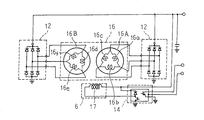
- FIG. 3 is a circuit diagram of a rotating electrical machine on which a stator according to an embodiment of the present invention is mounted
- FIG. 4 is a perspective view showing a stator according to an embodiment of the present invention
- FIG. 5 is a side view showing a stator according to an embodiment of the present invention
- FIG. 6 is a side view of the stator according to the embodiment of the present invention as viewed from the opposite side of FIG. 5
- FIG. FIG. 8 is a perspective view showing a stator according to an embodiment of the present invention
- FIG. 8 is a perspective view showing a stator according to an embodiment of the present invention.
- the rotating electrical machine includes a case 3 formed of a substantially bowl-shaped aluminum front bracket 1 and a rear bracket 2, a shaft 4 rotatably supported by the case 3, and a front side of the case 3.
- a pulley 5 fixed to the end of the extending shaft 4, a rotor 6 fixed to the shaft 4 and accommodated in the case 3, and a fan 7 fixed to both end faces of the rotor 6 in the axial direction.
- the rotor 6 is provided with a field winding 17 that generates a magnetic flux by passing an electric current, and a pair of pole cores 18 and 19 that are provided so as to cover the field winding 17 and form magnetic poles by the magnetic flux. It has.
- the pair of pole cores 18 and 19 are made of iron, and for example, eight claw-shaped magnetic poles 20 and 21 each having a substantially trapezoidal outermost surface shape project from the outer peripheral edge at an equiangular pitch in the circumferential direction. These claw-shaped magnetic poles 20 and 21 are fixed to the shaft 4 so as to face each other so as to mesh with each other.
- the stator 8 is composed of a cylindrical stator core 15 made of a laminate of magnetic steel plates and a stator winding 16 wound around the stator core 15. As shown in FIG. 2, for example, 96 slots 15 a that open to the inner diameter side are formed in the stator core 15 at an equiangular pitch in the circumferential direction. That is, the slots 15a are formed at a rate of two per phase per pole. An insulator (not shown) is mounted in each slot 15 a to ensure electrical insulation between the stator core 15 and the stator winding 16.
- a resin-made outer peripheral tape 24 is wound around the radially outer peripheral surfaces of the front side coil end group 16F and the rear side coil end group 16R of the stator winding 16, and the front side coil end group 16F and the rear side coil end group are wound.
- the varnish dropped and filled in 16R is prevented from flowing out.
- the storage position in the slot 15a of the conductor wire 30 is assumed to be address 1, address 2, address 3, address 4, address 5, and address 6 from the inner diameter side.
- the solid line indicates the connection state on the rear side of the stator core
- the dotted line indicates the connection state on the front side of the stator core
- the black circle indicates the joint portion, 1, 7, 13.
- Reference numeral 91 denotes a slot number.
- the a-phase winding 16a is composed of first to sixth windings 31 to 36 each formed of a single conductor wire 30 as a strand made of a continuous copper wire having a rectangular cross section that is insulated and coated.
- the conductor wire 30 that is an electric conductor includes a linear slot accommodating portion 30a arranged at a pitch of 6 slots and a turn portion 30b that alternately connects the ends of the adjacent slot accommodating portions 30a on the front side and the rear side. It consists of and.
- the conductor wire 30 is wound around the stator core 15 so that the slot accommodating portion 30a is accommodated in every six slots 15a.
- the first winding 31 is formed by undulating one conductor wire 30 in slots 15a every six slots from slot numbers 1 to 91 so as to alternately take addresses 2 and 1. .
- the second winding 32 is configured by winding one conductor wire 30 in slots 15a every six slots from slot numbers 1 to 91 so as to alternately take addresses 1 and 2. ing.
- the third winding 33 is formed by winding one conductor wire 30 in slots 15a every six slots from slot numbers 1 to 91 so as to alternately take addresses 4 and 3. ing.
- the fourth winding 34 is formed by wrapping one conductor wire 30 in slots 15a every six slots from slot numbers 1 to 91 so as to alternately take addresses 3 and 4. ing.
- the fifth winding 35 is formed by undulating one conductor wire 30 in slots 15a every six slots from slot numbers 1 to 91 so as to alternately take addresses 6 and 5.
- the sixth winding 36 is formed by winding one conductor wire 30 in slots 15a every six slots from slot numbers 1 to 91 so as to alternately take addresses 5 and 6. ing.
- the slot accommodating part 30a of the conductor wire 30 is surrounded by the insulator, and the longitudinal direction of the rectangular cross section is aligned in the radial direction, and six are arranged in a line in the radial direction.
- an end 31a of the first winding 31 extending from the 91st slot 15a and an end 33b of the third winding 33 extending from the 1st slot 15a are provided.
- TIG Tusten Inert Gas
- the end 33a of the third winding 33 extending from the 91st slot 15a and the end 35b of the fifth winding 35 extending from the 1st slot 15a Joining by TIG welding and joining the end 35a of the fifth winding 35 extending from the 91st slot 15a and the end 31b of the first winding 31 extending from the 1st slot 15a by TIG welding To do.
- the first winding 31, the third winding 33, and the fifth winding 35 are connected in series to form a three-turn wave winding.
- an end portion 34a of the fourth winding 34 extending from the 91st slot 15a and an end portion 32b of the second winding 32 extending from the first slot 15a are provided on the front side of the stator core 15.
- the ends 36a of the sixth winding 36 extending from the 91st slot 15a and the ends 34b of the fourth winding 34 extending from the first slot 15a are joined by TIG welding.
- the end portion 32a of the second winding 32 extending from the 91st slot 15a and the end portion 36b of the sixth winding 36 extending from the 1st slot 15a are joined by TIG welding. Accordingly, the second winding 32, the fourth winding 34, and the sixth winding 36 are connected in series to form a three-turn wave winding.
- the portion of the conductor wire 30 of the first winding 31 extending rearward from the 49th and 55th slots 15a is cut, and the second winding extending from the 55th and 61st slots 15a.
- the portions of the 32 conductor wires 30 are cut.
- the cut end 31d of the first winding 31 extending from the second address of the 49th slot 15a and the cut end 32d of the second winding 32 extending from the second address of the 55th slot 15a are TIG.
- a six-turn wave winding (a-phase winding 16a) in which the first to sixth windings 31 to 36 are connected in series is formed.
- the cut end 31d of the first winding 31 and the cut end 32d of the second winding 32 become the first and second lead portions that are connected to each other to form a phase winding. Further, a cut end 31c of the first winding 31 extending from the first address of the 55th slot 15a and a cut end 32c of the second winding 32 extending from the first address of the 61th slot 15a are: It is the both ends of the phase winding 16a, and becomes the third lead portion that becomes the lead wire.
- the slots 15a around which the conductor wires 30 are wound are shifted one slot at a time, and the d-phase winding 16d, the c-phase winding 16c, the f-phase winding 16f, the b-phase winding 16b, and An e-phase winding 16e is formed.
- the a-phase winding 16a is wound around the first, seventh,... 91 slot group, and the d-phase winding 16d is wound around the second, eighth,.
- the c-phase winding 16c is wound around the third, ninth,... 93 slot group, and the f-phase winding 16f is wound around the fourth, tenth,.
- the winding 16b is wound around the fifth, eleventh,..., 95th slot group, and the e-phase winding 16e is wound around the sixth, twelfth,.
- the end portions (third lead portions) of the a-phase winding 16a, b-phase winding 16b and c-phase winding 16c are connected ( ⁇ connection) to form a three-phase AC winding 16A.
- the end portions (third lead portions) of the d-phase winding 16d, the e-phase winding 16e, and the f-phase winding 16f are connected ( ⁇ connection) to form a three-phase AC winding 16B.
- the stator winding 16 composed of two sets of three-phase AC windings 16A and 16B that are ⁇ -connected is configured.
- connection terminal part of the ends of each phase winding of the three-phase AC windings 16A, 16B is electrically connected to the rectifier 12, and the AC voltages of the two three-phase AC windings 16A, 16B are respectively connected to the rectifier 12. Is rectified to a direct current and output.
- the turn portions 30b are arranged in three rows in the radial direction and arranged at a one-slot pitch in the circumferential direction, and are arranged as a first coil end group.
- a side coil end group 16F is configured.
- the turn portions 30b are arranged in three rows in the radial direction and aligned at a one-slot pitch in the circumferential direction, thereby constituting the rear side coil end group 16R which is the second coil end group. is doing.
- a method of connecting wave windings of three turns in the a-phase winding 16a, the b-phase winding 16b, and the c-phase winding 16c, and the a-phase winding 16a, the b-phase windings 16b and c A method for ⁇ -connecting the ends of the phase winding 16c will be described with reference to FIGS.
- the a-phase winding 16a as described above, the portion of the conductor wire 30 of the first winding 31 extending from the 49th and 55th slots 15a to the rear side is cut, and the 55th and 61st A portion of the conductor wire 30 of the second winding 32 extending from the slot 15a is cut.
- the portions of the conductor wire 30 of the first winding 31 extending from the slots 15a of the 51st and 57th to the rear side are cut, so that the 57th and 63rd. It is assumed that a portion of the conductor wire 30 of the second winding 32 extending from the slot 15a is cut.
- the portions of the conductor wire 30 of the first winding 31 extending to the rear side from the slots 15a of the 53rd and 59th are cut, and the 59th and 65th are wound. It is assumed that a portion of the conductor wire 30 of the second winding 32 extending from the slot 15a is cut.
- the cut end 31d of the first winding 31 extending from the second address of the 49th slot 15a of the a-phase winding 16a is used as a lead portion 16a1, and the first end of the 55th slot 15a is extended from the first address.
- the cut end 32d of the second winding 32 extending from address 2 of 55th slot 15a and the lead portion 16a 3 61 slot # the cut end 32c of the second winding 32 extending from address 1 15a and the lead portion 16a 4.
- the cut end 31d of the first winding 31 extending from Address 2 of # 53 slot 15a of the b-phase winding phase portion 16b and the lead portion 16b 1, extending from the first address of the 59th slot 15a the cut end 31c of the first winding 31 and a lead portion 16b 2, and a lead portion 16b 3 of the cut end 32d of the second winding 32 extending from address 2 of 59th slot 15a, 1 of 65th slot 15a the cut end 32c of the second winding 32 extending from the address and the lead portion 16b 4.
- the lead portions 16a 1 and 16a 3 correspond to the first and second lead portions connecting the three-turn wave windings constituting the a-phase winding 16a, and the lead portions 16a 2 and 16a 4 are a. It is the both ends of the phase winding 16a, and corresponds to the third lead portion constituting the lead wire.
- the lead portions 16b 1 and 16b 3 correspond to first and second lead portions that connect the three-turn wave windings constituting the b-phase winding 16b, and the lead portions 16b 2 and 16b 4 are b-phase. It is the both ends of the coil
- the lead portions 16c 1 and 16c 3 correspond to first and second lead portions that connect the three-turn wave windings constituting the c-phase winding 16c, and the lead portions 16c 2 and 16c 4 are c-phase windings. It is the both ends of line 16c, and is equivalent to the 3rd lead part which constitutes a lead line.
- the lead portion 16a 1 as the second lead portion is pulled out from the rear side coil end group 16R without being bent in the axial direction.
- the lead portion 16a 3 is a first lead portion is drawn without bending from the rear-end coil end group 16R in the axial direction, away from the axial outer peripheral surface of the rear-end coil end group 16R (hereinafter, referred to as top) 7 is secured at a predetermined position to ensure a predetermined gap from the top of the rear coil end group 16R, and is routed counterclockwise in FIG. 7 along the top of the rear coil end group 16R.
- the lead portion 16a 3 after being extended to the vicinity of the lead portion 16a 1, bent in the axial direction so as to close contact with the lead portion 16a 1, are bonded are TIG welded to the lead portion 16a 1. Accordingly, the three-turn wave winding in which the first winding 31, the third winding 33, and the fifth winding 35 are connected in series, the second winding 32, the fourth winding 34, and the sixth winding.
- a three-turn wave winding to which the winding 36 is connected in series is connected in series to form an a-phase winding 16a composed of a six-turn wave winding.
- the lead portion 16b 1 is a first lead portion is drawn without bending from the rear-end coil end group 16R in the axial direction, bent at a position away from the top of the rear-end coil end group 16R, rear A predetermined gap is secured from the top of the coil end group 16R, and the coil end group 16R is routed clockwise in FIG. 7 along the top of the rear coil end group 16R.
- the lead portion 16b 1 intersects the lead portion 16a 3 in a state in contact with the lead portion 16a 3.
- the lead portion 16c 1 is a second lead portion is drawn without bending from the rear-end coil end group 16R in the axial direction. Further, the lead portion 16c 3 as the first lead portion is pulled out from the rear side coil end group 16R without being bent in the axial direction, and is bent at a position away from the top of the rear side coil end group 16R. A predetermined gap is secured from the top of the coil end group 16R, and the coil end group 16R is routed counterclockwise in FIG. 7 along the top of the rear coil end group 16R. At this time, the lead portion 16c 3 intersects with the lead portion 16b 1 in contact with the lead portion 16b 1 and further intersects with the lead portion 16a 3 in contact with the lead portion 16a 3 .
- the lead portion 16c 3 after being extended to the vicinity of the lead portion 16c 1, bent in the axial direction so as to close contact with the lead portion 16c 1, are bonded are TIG welded to the lead portion 16c 1. Accordingly, the three-turn wave winding in which the first winding 31, the third winding 33, and the fifth winding 35 are connected in series, the second winding 32, the fourth winding 34, and the sixth winding. A three-turn wave winding with the winding 36 connected in series is connected in series to form a c-phase winding 16c composed of a six-turn wave winding.
- the lead portion 16a 2 and the lead portion 16c 2 which are the third lead portions that make a pair are pulled out without bending in the axial direction from the drawing position of the rear side coil end group 16R, and the rear side coil end group.
- the lead wire 16a 2 and the conductor wire 30 constituting the lead portion 16c 2 are bent at a position away from the top of the 16R, and in the direction opposite to the drawing direction from the slot and radially outward. Then, it is folded back in a U shape and extends inward in the radial direction, approaching each other and integrally connected to the connection fitting 25.
- the lead portion 16b 2 and the lead portion 16a 4 which are the third lead portions that make a pair are drawn out from the drawing position of the rear side coil end group 16R without bending in the axial direction, and the rear side coil end group 16R. As shown in FIG. 8, it is bent at a position away from the top of the wire and extends outward in the radial direction, then folded back into a U shape and extends inward in the radial direction. Connected to.
- a lead portion 16c 4 is a third lead portion forming a pair and the lead portion 16b 4 are pulled out without bending the pull-out position of the rear-end coil end group 16R in the axial direction, rear-end coil end group 16R
- the lead wire 16c 4 and the conductor wire 30 constituting the lead portion 16b 4 are bent in the same direction as the lead-out direction from the slot and radially outward as shown in FIG. Then, it is folded back in a U shape and extends in the radial direction, and is connected to the connection fitting 25 in close proximity to each other.
- Each third lead portion is bent so as not to extend radially outward from the end surface of the stator core 15 when viewed from the axially outer side.
- the a-phase winding 16a, the b-phase winding 16b, and the c-phase winding 16c are ⁇ -connected to form a three-phase AC winding 16A. Then, the three-phase AC winding 16 ⁇ / b> A is connected to the rectifier 12 via the three connection fittings 25.
- each of the d-phase winding 16d, the e-phase winding 16e, and the f-phase winding 16f is similarly pulled out from the rear coil end group in the axial direction.
- the coil is bent at a position away from the top of the side coil end group, crosses at least one other first lead portion, and is routed in the circumferential direction along the top of the rear side coil end group. It is configured to be joined to a corresponding second lead portion drawn in the axial direction from the group 16R.
- the three-phase AC winding 16B is also configured by ⁇ -connecting the third lead portion constituted by the end portions of the d-phase winding 16d, the e-phase winding 16e, and the f-phase winding 16f.
- the first lead portions of the six phase windings are drawn from the rear side coil end group, and are then separated from the top portion of the rear side coil end group and circumferentially along the top portion. Therefore, a gap is secured between the first lead portion and the rear side coil end group. Therefore, the reduction of the area of the second lead portion and the rear coil end group exposed to the cooling air is suppressed, and an excessive temperature rise of the stator winding is suppressed.
- the direction of engine vibration due to the piston movement of the engine is mainly the direction orthogonal to the axial direction of the shaft of the AC generator. Therefore, a large vibration is applied in the radial direction of the rotating electrical machine during engine operation.
- the first lead portion since the first lead portion is located axially outwardly away from the top of the rear side coil end group, the first lead portion vibrates in the radial direction during engine operation. However, there is no interference with the rear side coil end group, and the occurrence of disconnection or the like of the first lead portion due to the interference with the rear side coil end group is suppressed.
- the entire first lead portion Since the first lead portion routed in the circumferential direction along the top of the rear side coil end group intersects at least one other first lead portion in a close state, the entire first lead portion The rigidity of can be increased. Therefore, since vibration of the first lead portion is suppressed, occurrence of damage to the rear side coil end group due to disconnection of the first lead portion or rubbing with the first lead portion can be suppressed. In addition, since it is not necessary to form a regulating recess or the like for regulating the displacement of the first lead portion in the rear coil end group, the first lead portions can be fixed without taking time and cost. Furthermore, since it is not necessary to use an adhesive or the like, the heat dissipation is not deteriorated, and process management and member management according to various manufacturing countries, seasons, working environments, etc. are not required.
- first lead portions are closely intersected with the lead portions routed in parallel, the first lead portions that are in close contact with each other are joined at different positions in the circumferential direction. Therefore, the first lead portion that is in close contact with the joint portion of the other first lead portion that is in close contact does not interfere.
- the first lead portion in the first three-phase AC winding is designated as No. 49. It can be composed of conductor wires drawn from slots up to 59. That is, since the first lead portion can be constituted by a conductor wire drawn out from a slot located in a narrow circumferential range from No. 49 to No. 59, the circumferential length of the first lead portion can be shortened, and the first lead The vibration resistance of the first lead portion is further enhanced in combination with the structure that intersects the portions.
- the third lead portions forming a pair are pulled out from the rear side coil end group in the axial direction and then bent so that the third lead portions are bent from the slot of the conductor wire constituting the third lead portion itself in the direction opposite to the pull-out direction. Since the lead wire connected to the rectifier 12 is formed by extending outward in the direction, then folding back in the U shape and extending inward in the radial direction, and joining the ends thereof, the arrangement of the lead wire The degree of freedom is expanded.
- the conductor wire which comprises a 3rd lead part is withdraw
- each rear first coil end group is configured.
- the lead position in the radial direction and the circumferential direction from the rear side coil end group of the lead portion can be specified from the design stage. Therefore, for example, from the viewpoint of increasing the mass productivity of the stator, the first lead portion is pulled out from the rear side coil end group so that the crossing form and the crossing position of each crossing portion of the first lead portions are optimal. You can set the position.
- the first lead portions are described as closely intersecting with each other. However, the first lead portions do not necessarily intersect closely with each other via a minute gap. You may cross. In this case, even if vibration or the like is applied to the first lead portion, the first lead portion is displaced, and the displaced first lead portions come into contact with each other. Therefore, the vibration is absorbed by the contact between the first lead portions, and the occurrence of abnormal vibration is suppressed.
- the stator winding includes a set of three-phase AC windings obtained by ⁇ -connecting the a-phase winding, the b-phase winding and the c-phase winding, and the d-phase winding.
- the e-phase winding and the f-phase winding are described as being composed of another set of three-phase AC windings obtained by ⁇ connection. Obtained by Y-connecting a set of three-phase AC windings obtained by Y-connecting wires, b-phase windings and c-phase windings, and d-phase windings, e-phase windings and f-phase windings It may be composed of another set of three-phase AC windings.
- stator winding includes a phase winding in which an a phase winding and a d phase winding are connected in series, a phase winding in which a b phase winding and an e phase winding are connected in series, and a c phase.
- a phase winding in which a winding and an f-phase winding are connected in series may be constituted by a Y-connection or a set of three-phase AC windings obtained by ⁇ -connection.
- the stator core formed with the ratio of the number of slots per phase per pole of 2 is used, but the number of slots per phase per pole is not limited to 2.
- a stator core having one slot per pole per phase may be used.
- the stator winding is composed of three phase windings.
- the stator core in which the slot is formed in the equiangular pitch in the circumferential direction is used. That is, in the above-described embodiment, the slots are formed at an equiangular pitch with the interval between the center lines of adjacent slot openings being ⁇ 0 °.
- each winding constituting the phase winding of the stator winding is manufactured using a conductor wire made of a continuous wire, but each winding constituting the phase winding of the stator winding is made. You may produce a line
- the cross-sectional rectangular conductor wire is used, the cross-sectional shape of a conductor wire is not limited to a rectangle, For example, a circular cross section may be sufficient.
- the first lead portion can be easily routed in the circumferential direction, and the manufacturability is improved.
- the first to sixth windings are connected based on the connection method shown in FIG.
- the first to sixth winding connection methods are the same. It is not limited, and is appropriately set according to a desired circuit configuration.
- the turn portions are arranged in three rows in the radial direction and arranged at a one-slot pitch in the circumferential direction to form the first and second coil end groups.
- the number of rows of turn portions arranged in a row is not limited to three rows, and may be, for example, one row, two rows, and four rows.
Landscapes
- Engineering & Computer Science (AREA)
- Power Engineering (AREA)
- Windings For Motors And Generators (AREA)
Abstract
Description
また、他の従来の回転電機の固定子では、規制凹部がコイルエンド群の頂部に設けられ、リード部が規制凹部内に嵌め込まれ、接着剤によりコイルエンド群に固定されている(例えば、特許文献2参照)。
まず、固定子巻線16を構成する1相分の巻線構造について図2を参照しつつ説明する。ここで、説明の便宜上、導体線30のスロット15a内の収納位置を内径側から1番地、2番地、3番地、4番地、5番地および6番地とする。また、図2中、実線は固定子鉄心のリア側の結線状態を示し、点線は固定子鉄心のフロント側の結線状態を示し、黒丸は接合部を示し、1,7,13・・・,91はスロット番号を示している。
この電気導体である導体線30は、6スロットピッチで配列された直線状のスロット収納部30aと、隣接するスロット収納部30aの端部同士をフロント側およびリア側で交互に連結するターン部30bとから構成されている。そして、導体線30が、スロット収納部30aを6スロット毎のスロット15aに収納されて固定子鉄心15に波巻きに巻装されている。
なお、各第3リード部は、軸方向外方から見て、固定子鉄心15の端面から径方向外方に延出しないように曲げ成形される。
また、矩形断面の導体線のスロット収納部が矩形断面の長手方向を径方向に揃えて径方向に1列に6本並んで配列されているので、導体線の占積率が高められる。
また、上記実施の形態では、スロットが周方向に等角ピッチに形成されている固定子鉄心を用いている。つまり、上記実施の形態では、スロットは、隣り合うスロット開口部の中心線間の間隔をα0°とする等角ピッチに形成されている。しかし、スロットが、隣り合うスロット開口部の中心線間の間隔をα1°とα2°(≠α1)とを交互にとる不等ピッチに形成されている固定子鉄心を用いてもよい。
また、上記実施の形態では、断面矩形の導体線を用いるものとしているが、導体線の断面形状は矩形に限定されるものではなく、例えば円形断面でも良い。この場合、第1リード部の周方向への引き回しが容易となり、製作性が向上する。
また、上記実施の形態では、第1巻線乃至第6巻線を図2に示される結線方法に基づいて結線するものとしているが、第1巻線乃至第6巻線の結線方法のこれに限定されるものではなく、所望の回路構成に合わせて適宜設定される。
また、上記実施の形態では、ターン部が径方向に3列に並んで周方向に1スロットピッチで整列されて配列されて第1および第2コイルエンド群を構成するものとしているが、径方向に並ぶターン部の列数は3列に限定されるものではなく、例えば1列、2列、4列でもよい。
Claims (7)
- スロットが内周側に開口するように周方向に所定のピッチで配列された円筒状の固定子鉄心と、上記スロット内に装着されて上記固定子鉄心に巻装され、該固定子鉄心の軸方向両端部に第1コイルエンド群および第2コイルエンド群を形成する固定子巻線と、上記固定子巻線の一部で構成され、上記第2コイルエンド群から軸方向に引き出されて、該第2コイルエンド群の表面との間に隙間を確保して、かつ該第2コイルエンド群の表面に沿って周方向に延設されている複数の第1リード部と、を備えた車両用回転電機の固定子において、
上記複数の第1リード部のそれぞれが、少なくとも1本の他の上記第1リード部と交差して上記第2コイルエンド群の表面に沿って周方向に延設されていることを特徴とする車両用回転電機の固定子。 - 上記固定子巻線の一部で構成され、上記第2コイルエンド群から軸方向に引き出された複数の第2リード部を備え、
上記複数の第1リード部のそれぞれが、上記第2コイルエンド群から軸方向に引き出され、該第2コイルエンド群の表面から離反した位置で曲げられ、該第2コイルエンド群の表面に沿って周方向に延びて上記複数の第2リード部の中の選択された第2リード部の近傍まで引き回され、その後軸方向に曲げられて、該選択された第2リード部に接合されていることを特徴とする請求項1記載の車両用回転電機の固定子。 - 上記固定子巻線の一部で構成され、それぞれ口出し線を構成する複数組の第3リード部を備え、
上記複数組の第3リード部の少なくとも1組の第3リード部が、上記第2コイルエンド群から引き出され、該第2コイルエンド群の表面から離反した位置で曲げられて該第3リード部を構成する導体線のスロットからの引き出し方向と逆向きに、かつ径方向外方に延び、上記固定子鉄心の軸方向端部の軸方向上方位置でU字状に折り返されて径方向内方に延びて、その端部同士を接合されていることを特徴とする請求項1又は請求項2記載の車両用回転電機の固定子。 - 上記複数組の第3リード部のそれぞれは、上記第2コイルエンド群の最内周部から引き出されていることを特徴とする請求項1乃至請求項3のいずれか1項に記載の車両用回転電機の固定子。
- 上記固定子巻線は、2組の三相交流巻線から構成されていることを特徴とする請求項1乃至請求項4のいずれか1項に記載の車両用回転電機の固定子。
- 上記2組の三相交流巻線のそれぞれは、Δ結線された三相交流巻線であることを特徴とする請求項5記載の車両用回転電機の固定子。
- 上記第2コイルエンド群は、上記固定子巻線の一部であるターン部が周方向に整列されて構成されていることを特徴とする請求項1乃至請求項6のいずれか1項に記載の車両用回転電機の固定子。
Priority Applications (7)
| Application Number | Priority Date | Filing Date | Title |
|---|---|---|---|
| EP08790772.1A EP2296254B1 (en) | 2008-07-01 | 2008-07-01 | Stator for rotary electric machine for vehicle |
| JP2010518849A JP5524837B2 (ja) | 2008-07-01 | 2008-07-01 | 車両用回転電機の固定子 |
| US13/002,273 US8686610B2 (en) | 2008-07-01 | 2008-07-01 | Automotive dynamoelectric stator |
| CN200880130212.4A CN102077444B (zh) | 2008-07-01 | 2008-07-01 | 车用旋转电机的定子 |
| KR1020107028036A KR101166314B1 (ko) | 2008-07-01 | 2008-07-01 | 차량용 회전 전기기계의 고정자 |
| PCT/JP2008/061909 WO2010001463A1 (ja) | 2008-07-01 | 2008-07-01 | 車両用回転電機の固定子 |
| TW097130211A TWI393327B (zh) | 2008-07-01 | 2008-08-08 | 車輛用旋轉電機之固定子 |
Applications Claiming Priority (1)
| Application Number | Priority Date | Filing Date | Title |
|---|---|---|---|
| PCT/JP2008/061909 WO2010001463A1 (ja) | 2008-07-01 | 2008-07-01 | 車両用回転電機の固定子 |
Publications (1)
| Publication Number | Publication Date |
|---|---|
| WO2010001463A1 true WO2010001463A1 (ja) | 2010-01-07 |
Family
ID=41465579
Family Applications (1)
| Application Number | Title | Priority Date | Filing Date |
|---|---|---|---|
| PCT/JP2008/061909 WO2010001463A1 (ja) | 2008-07-01 | 2008-07-01 | 車両用回転電機の固定子 |
Country Status (7)
| Country | Link |
|---|---|
| US (1) | US8686610B2 (ja) |
| EP (1) | EP2296254B1 (ja) |
| JP (1) | JP5524837B2 (ja) |
| KR (1) | KR101166314B1 (ja) |
| CN (1) | CN102077444B (ja) |
| TW (1) | TWI393327B (ja) |
| WO (1) | WO2010001463A1 (ja) |
Cited By (2)
| Publication number | Priority date | Publication date | Assignee | Title |
|---|---|---|---|---|
| JP2015050884A (ja) * | 2013-09-04 | 2015-03-16 | 株式会社デンソー | 回転電機の固定子 |
| JP7479460B2 (ja) | 2019-10-04 | 2024-05-08 | ヴァレオ エキプマン エレクトリク モトゥール | 回転電気機械用の電気巻線 |
Families Citing this family (13)
| Publication number | Priority date | Publication date | Assignee | Title |
|---|---|---|---|---|
| KR100361592B1 (ko) * | 2000-09-28 | 2002-11-22 | 한불화장품주식회사 | 백지, 고본 추출물 및 이 추출물을 함유하는 화장료 조성물 |
| KR100416400B1 (ko) * | 2001-02-14 | 2004-01-31 | 우원홍 | 천화분 추출물의 제조방법 및 이를 함유하는 피부 미백용외용제 조성물 |
| KR100512930B1 (ko) * | 2002-12-14 | 2005-09-07 | 제천시 | 한약재를 함유한 목욕용 조성물 및 이를 이용한 목욕제 |
| JP5073005B2 (ja) | 2010-04-27 | 2012-11-14 | 三菱電機株式会社 | 回転電機 |
| JP5635470B2 (ja) | 2011-09-22 | 2014-12-03 | 日立オートモティブシステムズ株式会社 | 回転電機および回転電機の製造方法 |
| KR101998420B1 (ko) * | 2012-12-26 | 2019-07-09 | 현대모비스 주식회사 | 헤어핀 접속기구 및 이를 구비한 헤어핀 권선모터 |
| FR3020208B1 (fr) * | 2014-04-17 | 2018-02-23 | Valeo Equipements Electriques Moteur | Stator de machine electrique muni de chignons a hauteur adaptee et procede de realisation du stator bobine correspondant |
| EP3306787A1 (en) * | 2014-09-19 | 2018-04-11 | Mitsubishi Electric Corporation | Method for manufacturing a stator, and method for manufacturing a rotary electric machine |
| WO2016166848A1 (ja) * | 2015-04-15 | 2016-10-20 | 三菱電機株式会社 | 固定子および回転電機 |
| TW201720024A (zh) | 2015-11-26 | 2017-06-01 | 財團法人工業技術研究院 | 一種電機集電裝置 |
| US10725531B1 (en) | 2018-05-15 | 2020-07-28 | Amazon Technologies, Inc. | Mitigating thermal increases in electronic devices |
| CN110311486B (zh) * | 2019-07-01 | 2021-02-26 | 东南大学 | 一种无刷双馈电机双笼转子及导条连接方法 |
| CN114204725B (zh) * | 2022-02-16 | 2022-05-31 | 珠海英搏尔电气股份有限公司 | 定子组件、电机、动力总成和交通工具 |
Citations (5)
| Publication number | Priority date | Publication date | Assignee | Title |
|---|---|---|---|---|
| JPS5130565Y1 (ja) * | 1967-05-12 | 1976-08-02 | ||
| JP2001103697A (ja) | 1998-11-25 | 2001-04-13 | Denso Corp | 回転電機の固定子 |
| JP2004023916A (ja) | 2002-06-18 | 2004-01-22 | Denso Corp | 回転電機の固定子 |
| JP2004350381A (ja) * | 2003-05-21 | 2004-12-09 | Mitsubishi Electric Corp | 回転電機の固定子 |
| JP2006211810A (ja) * | 2005-01-27 | 2006-08-10 | Denso Corp | セグメント連接型回転電機 |
Family Cites Families (9)
| Publication number | Priority date | Publication date | Assignee | Title |
|---|---|---|---|---|
| JPH05130565A (ja) | 1991-11-01 | 1993-05-25 | Hitachi Ltd | マルチメデイアコンパクトデイスク用再生装置 |
| JP3155532B1 (ja) | 1999-12-01 | 2001-04-09 | 三菱電機株式会社 | 車両用交流発電機の固定子 |
| JP4046270B2 (ja) | 2002-05-24 | 2008-02-13 | 三菱電機株式会社 | 回転電機の固定子 |
| JP4162081B2 (ja) * | 2002-12-06 | 2008-10-08 | 三菱電機株式会社 | 車両用交流発電機 |
| JP2004215358A (ja) * | 2002-12-27 | 2004-07-29 | Toyota Motor Corp | 多相モータ装置 |
| JP2004229460A (ja) * | 2003-01-27 | 2004-08-12 | Mitsubishi Electric Corp | 回転電機の固定子 |
| DE10318816B4 (de) | 2003-04-17 | 2007-06-28 | Minebea Co., Ltd. | Stator mit Verschaltungsstruktur für Statorwicklungen |
| JP2007159192A (ja) * | 2005-12-01 | 2007-06-21 | Matsushita Electric Ind Co Ltd | 無刷子電動機及びそれを具備した密閉型圧縮機 |
| JP4353950B2 (ja) | 2006-03-06 | 2009-10-28 | 三菱電機株式会社 | 回転電機 |
-
2008
- 2008-07-01 CN CN200880130212.4A patent/CN102077444B/zh active Active
- 2008-07-01 WO PCT/JP2008/061909 patent/WO2010001463A1/ja active Application Filing
- 2008-07-01 EP EP08790772.1A patent/EP2296254B1/en active Active
- 2008-07-01 KR KR1020107028036A patent/KR101166314B1/ko active IP Right Grant
- 2008-07-01 US US13/002,273 patent/US8686610B2/en active Active
- 2008-07-01 JP JP2010518849A patent/JP5524837B2/ja not_active Expired - Fee Related
- 2008-08-08 TW TW097130211A patent/TWI393327B/zh not_active IP Right Cessation
Patent Citations (5)
| Publication number | Priority date | Publication date | Assignee | Title |
|---|---|---|---|---|
| JPS5130565Y1 (ja) * | 1967-05-12 | 1976-08-02 | ||
| JP2001103697A (ja) | 1998-11-25 | 2001-04-13 | Denso Corp | 回転電機の固定子 |
| JP2004023916A (ja) | 2002-06-18 | 2004-01-22 | Denso Corp | 回転電機の固定子 |
| JP2004350381A (ja) * | 2003-05-21 | 2004-12-09 | Mitsubishi Electric Corp | 回転電機の固定子 |
| JP2006211810A (ja) * | 2005-01-27 | 2006-08-10 | Denso Corp | セグメント連接型回転電機 |
Cited By (2)
| Publication number | Priority date | Publication date | Assignee | Title |
|---|---|---|---|---|
| JP2015050884A (ja) * | 2013-09-04 | 2015-03-16 | 株式会社デンソー | 回転電機の固定子 |
| JP7479460B2 (ja) | 2019-10-04 | 2024-05-08 | ヴァレオ エキプマン エレクトリク モトゥール | 回転電気機械用の電気巻線 |
Also Published As
| Publication number | Publication date |
|---|---|
| TW201004106A (en) | 2010-01-16 |
| US8686610B2 (en) | 2014-04-01 |
| JPWO2010001463A1 (ja) | 2011-12-15 |
| CN102077444A (zh) | 2011-05-25 |
| EP2296254A1 (en) | 2011-03-16 |
| TWI393327B (zh) | 2013-04-11 |
| CN102077444B (zh) | 2013-10-30 |
| KR101166314B1 (ko) | 2012-07-18 |
| US20110109178A1 (en) | 2011-05-12 |
| EP2296254A4 (en) | 2014-01-15 |
| KR20110018357A (ko) | 2011-02-23 |
| JP5524837B2 (ja) | 2014-06-18 |
| EP2296254B1 (en) | 2015-03-04 |
Similar Documents
| Publication | Publication Date | Title |
|---|---|---|
| JP5524837B2 (ja) | 車両用回転電機の固定子 | |
| JP4497008B2 (ja) | 車両用回転電機の固定子 | |
| JP4046270B2 (ja) | 回転電機の固定子 | |
| JP3621635B2 (ja) | 回転電機 | |
| JP4187914B2 (ja) | 回転電機の固定子 | |
| JP4014071B2 (ja) | 交流発電機及びその巻線アッセンブリ並びに巻線アッセンブリの製造方法 | |
| KR101107884B1 (ko) | 차량용 회전 전기기계 | |
| JP5541585B2 (ja) | 回転電機 | |
| JP3566665B2 (ja) | 回転電機の固定子 | |
| KR20020040536A (ko) | 차량용 교류발전기 | |
| JP4497102B2 (ja) | 車両用回転電機の固定子 | |
| US9847684B2 (en) | Stator and rotating electric machine | |
| JPWO2015029579A1 (ja) | 回転電機 | |
| JP2009131092A (ja) | 回転電機の固定子および回転電機 | |
| JP2004350381A (ja) | 回転電機の固定子 | |
| JP4162081B2 (ja) | 車両用交流発電機 | |
| JP7468301B2 (ja) | 回転電機 | |
| JP4450235B2 (ja) | 交流発電機 | |
| JP3864878B2 (ja) | 高電圧回転電機 | |
| JP3808434B2 (ja) | 回転電機の固定子 | |
| JP4476199B2 (ja) | 回転電機の固定子 | |
| JP2019115173A (ja) | ステータ | |
| JP5909789B2 (ja) | 回転電機、回転電機用ステータおよび車両 |
Legal Events
| Date | Code | Title | Description |
|---|---|---|---|
| WWE | Wipo information: entry into national phase |
Ref document number: 200880130212.4 Country of ref document: CN |
|
| 121 | Ep: the epo has been informed by wipo that ep was designated in this application |
Ref document number: 08790772 Country of ref document: EP Kind code of ref document: A1 |
|
| ENP | Entry into the national phase |
Ref document number: 2010518849 Country of ref document: JP Kind code of ref document: A |
|
| WWE | Wipo information: entry into national phase |
Ref document number: 2008790772 Country of ref document: EP |
|
| ENP | Entry into the national phase |
Ref document number: 20107028036 Country of ref document: KR Kind code of ref document: A |
|
| WWE | Wipo information: entry into national phase |
Ref document number: 13002273 Country of ref document: US |
|
| WWE | Wipo information: entry into national phase |
Ref document number: 3/CHENP/2011 Country of ref document: IN |
|
| NENP | Non-entry into the national phase |
Ref country code: DE |