WO2014157621A1 - ステータの構造 - Google Patents
ステータの構造 Download PDFInfo
- Publication number
- WO2014157621A1 WO2014157621A1 PCT/JP2014/059130 JP2014059130W WO2014157621A1 WO 2014157621 A1 WO2014157621 A1 WO 2014157621A1 JP 2014059130 W JP2014059130 W JP 2014059130W WO 2014157621 A1 WO2014157621 A1 WO 2014157621A1
- Authority
- WO
- WIPO (PCT)
- Prior art keywords
- stator
- coil
- axial
- end portion
- yoke
- Prior art date
Links
Images


Classifications
-
- H—ELECTRICITY
- H02—GENERATION; CONVERSION OR DISTRIBUTION OF ELECTRIC POWER
- H02K—DYNAMO-ELECTRIC MACHINES
- H02K3/00—Details of windings
- H02K3/04—Windings characterised by the conductor shape, form or construction, e.g. with bar conductors
- H02K3/12—Windings characterised by the conductor shape, form or construction, e.g. with bar conductors arranged in slots
-
- H—ELECTRICITY
- H02—GENERATION; CONVERSION OR DISTRIBUTION OF ELECTRIC POWER
- H02K—DYNAMO-ELECTRIC MACHINES
- H02K15/00—Methods or apparatus specially adapted for manufacturing, assembling, maintaining or repairing of dynamo-electric machines
- H02K15/0025—Shaping or compacting conductors or winding heads after the installation of the winding in the core or machine ; Applying fastening means on winding heads
- H02K15/0037—Shaping or compacting winding heads
-
- H—ELECTRICITY
- H02—GENERATION; CONVERSION OR DISTRIBUTION OF ELECTRIC POWER
- H02K—DYNAMO-ELECTRIC MACHINES
- H02K3/00—Details of windings
- H02K3/04—Windings characterised by the conductor shape, form or construction, e.g. with bar conductors
- H02K3/28—Layout of windings or of connections between windings
-
- H—ELECTRICITY
- H02—GENERATION; CONVERSION OR DISTRIBUTION OF ELECTRIC POWER
- H02K—DYNAMO-ELECTRIC MACHINES
- H02K3/00—Details of windings
- H02K3/46—Fastening of windings on the stator or rotor structure
- H02K3/50—Fastening of winding heads, equalising connectors, or connections thereto
Definitions
- the present invention relates to a structure of a stator, and in particular, two slot portions that are arranged in a plurality of circumferential directions with respect to a stator core and are formed by rectangular conductors having a rectangular cross section and are accommodated in different slots. And a coil end portion that protrudes from the axial end face of the stator core toward the outside in the axial direction and connects the two slot portions to each other.
- a stator including a stator core and a stator coil is known (for example, see Patent Document 1).
- the stator core is formed between an annularly formed yoke, a plurality of teeth projecting radially inward from the radially inner side surface of the yoke, and two teeth adjacent in the circumferential direction. And a slot.
- a plurality of stator coils are arranged in the circumferential direction with respect to the stator core.
- Each stator coil has two slot portions accommodated in different slots, and two coil end portions projecting outward in the axial direction from both axial end surfaces of the stator core. Each coil end portion connects two slot portions on both sides.
- each stator coil is formed such that both the slot portion and the coil end portion extend substantially linearly in the axial direction when viewed from the side. Both end portions of each stator coil are bent from a linear portion extending in the axial direction and extend outward in the radial direction. Further, both end portions of each stator coil are joined to end portions of other stator coils existing in the circumferential direction. The end portions of the stator coil are joined to each other at a position away from the radially outer end of the stator coil radially outward (see FIG. 3 and the like).
- each stator coil is formed such that both the slot portion and the coil end portion extend substantially linearly in the axial direction when viewed from the side. For this reason, since the total axial length of the stator becomes relatively large, there is a possibility that the mounting may become impossible if there is a restriction on the space in which the stator can be accommodated. On the other hand, in order to shorten the overall axial length of the stator, it is conceivable to shorten the overall axial length of the stator core. However, this makes it difficult to generate a desired magnetic field in the stator, which decreases the stator performance. There is a possibility of being invited.
- the present invention has been made in view of the above-described points, and an object of the present invention is to provide a stator structure capable of shortening the overall length in the axial direction without causing performance degradation.
- One aspect of the present invention includes a yoke (20) formed in an annular shape, a plurality of teeth (22) protruding radially from the radial side surface of the yoke (20), and two circumferentially adjacent two A stator core (12) having slots (24) formed between the teeth (22), and a plurality of circumferentially arranged stator cores (12) with a rectangular cross section.
- stator coil (14) having a coil end portion (34, 36) connecting the slot portions (30, 32), and a stator coil (1), each stator coil (1 ) Of the coil end portion (34, 36) is inclined toward the yoke (20) side in the radial direction with respect to the slot portion (30, 32) extending in the axial direction, and one stator coil ( 14) and the other end of the other stator coil (14) are joined at a position opposite to the yoke (20) side in the radial direction with respect to the inclined coil end portion (34).
- the axial distance from the axial end surface of the stator core (12) is that the coil end portion (34) that is inclined is not inclined, the coil from the axial end surface of the stator core (12) It is a structure of the stator (10) performed in the position shorter than the axial direction distance to the vertex of an end part (34).
- the overall length in the axial direction can be shortened without causing performance degradation.
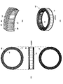
- stator which is one Example of this invention. It is a block diagram of the stator of a present Example. It is a perspective view of each stator coil with which the stator of a present Example is provided. It is the figure showing the state by which some stator coils were assembled
- FIG. 1 shows a perspective view of a stator according to an embodiment of the present invention.
- FIG. 2 shows a configuration diagram of the stator of this embodiment.
- FIG. 2A a top view and a bottom view are shown on the left and right halves
- FIG. 2B is a side view and a cross-sectional view on the left and right halves.
- FIG. 3 is a perspective view of each stator coil included in the stator of this embodiment.
- FIG. 4 is a diagram illustrating a state in which a part of the stator coil is assembled to the stator core of the present embodiment.
- FIG. 5 is a diagram showing a state in which all the stator coils are assembled to the stator core of the present embodiment.
- 4 (A) and 5 (A) are perspective views, FIGS.
- FIGS. 4 (B) and 5 (B) are enlarged perspective views of main parts, and FIGS. 4 (C) and 5 (B).
- (C) shows a top view, a side view, and a bottom view, respectively.
- FIG. 6 is a view showing the main part of the stator of this embodiment. 6A shows a cross-sectional view of the main part, and FIG. 6B shows a perspective view of the stator whose cross-section is shown in FIG. 6A.
- FIG. 7 shows the figure showing the positional relationship of the principal part of the stator of a present Example.
- FIG. 7 shows a cross-sectional view of the main part.
- the stator 10 is a stator used in a rotating electric machine such as a three-phase AC motor.
- the stator 10 is disposed radially outside the rotor as a rotor via a predetermined air gap, and generates a magnetic field that rotates the rotor when energized.
- the stator 10 includes a stator core 12 and a stator coil 14.
- the stator core 12 is a member formed in a hollow cylindrical shape.
- the stator core 12 may be formed by laminating a plurality of insulating coated steel sheets in the axial direction.
- a cylindrical yoke 16 formed of a material obtained by compression-molding a soft magnetic powder coated with an insulating coating may be attached to the outer surface in the radial direction of the stator core 12.
- the stator core 12 has a yoke 20 formed in an annular shape, and teeth 22 protruding from the radially inner side surface of the yoke 20 toward the radially inner side (axial center side).
- a plurality (for example, 96) of teeth 22 are provided in the circumferential direction on the radially inner side surface of the yoke 20, and are provided at regular intervals along the circumferential direction.
- the stator core 12 has a slot 24 formed between two teeth 22 adjacent in the circumferential direction. The slots 24 are provided between two adjacent teeth 22 in the circumferential direction.
- the stator coil 14 is wound around each tooth 18.
- a plurality of (eg, 96) stator coils 14 are arranged in the circumferential direction on the radially inner side of the stator core 12.
- a plurality of stator coils 14 are arranged in the circumferential direction to constitute a coil assembly 26.
- the coil assembly 26 is formed in an annular shape by arranging a plurality of stator coils 14 side by side in the circumferential direction.
- slots 24 that accommodate a plurality of stator coils 14 are arranged while being shifted one by one in the circumferential direction, and two stator coils 14 that are separated from each other by a predetermined distance in the circumferential direction for each slot 24.
- the coil 14 is configured to overlap in the stacking direction (that is, the radial direction) around which the conducting wire circulates.
- Each stator coil 14 constitutes one of a U-phase coil, a V-phase coil, and a W-phase coil when the stator 10 is applied to, for example, a three-phase AC motor.
- the U-phase coil, the V-phase coil, and the W-phase coil that are the stator coils 14 are wound around the teeth 22 in that order in the circumferential direction.
- the stator core 12 includes a plurality of (for example, 48) divided cores 28 divided in the circumferential direction. That is, the stator core 12 is divided into a plurality of divided cores 28 in the circumferential direction. All the divided cores 28 have the same shape as each other, and specifically have a shape including the yoke 20 and the two teeth 22 corresponding to the same circumferential angle. An insulating member that secures insulation between the stator core 12 and the stator coil 14 is attached to each divided core 28.
- the split core 28 with the insulating member is inserted into the coil assembly 26 from the outside in the radial direction so that the stator coil 14 of the coil assembly 26 is disposed in the slot 24 between the two teeth 22.
- the stator 10 in which the stator core 12 and the stator coil 14 are assembled is configured.
- the stator coil 14 is constituted by a rectangular conducting wire having a rectangular cross section (specifically, a rectangular shape).
- the flat conducting wire only needs to be made of a highly conductive metal such as copper or aluminum, and the corner portion of the flat conducting wire may be R-processed.
- a plurality of stator coils 14 arranged in the circumferential direction of the stator 10 are concentric coils that are formed by bending a rectangular conductive wire that has been wound by a predetermined number of turns (for example, 5 turns).
- Each stator coil 14 is first formed into a substantially elliptical shape while being wound around a predetermined number of turns by winding a rectangular conductor wire as a single straight wire wound around a winding jig, By bending using a molding apparatus, as shown in FIG. 3, it is formed in a substantially hexagonal shape while being circulated by a predetermined number of turns.
- Each stator coil 14 has slot portions 30 and 32 and coil end portions 34 and 36.
- the slot portions 30 and 32 are portions accommodated in the slots 24 formed in the stator core 12.
- the coil end portions 34 and 36 are portions that protrude outward in the axial direction from both axial end portions of the stator core 12.
- Each of the two slot portions 30 and 32 extends substantially linearly so as to penetrate different slots 24 that are separated by a predetermined distance in the circumferential direction in the axial direction.
- the two coil end portions 34 and 36 are curved so as to connect the two circumferential circumferential slot portions 30 and 32 to each other on the axially outer side of the axial end surface of the stator core 12.
- both end portions of each stator coil 14 protrude outward in the axial direction from the same axial end surface of one of the axial end surfaces of the stator core 12 in order to connect to other stator coils 14 and terminals. Further, both end portions of all the stator coils 14 constituting the coil assembly 26 protrude outward in the axial direction from one same axial end surface of the axial end surfaces of the stator core 12.
- the side from which both ends of the stator coil 14 protrude is referred to as an axial lead side
- the opposite side to the axial lead side is referred to as an axial anti-lead side.
- the coil end portion 34 is provided on the axial lead side, and the coil end portion 36 is provided on the axially opposite lead side.
- the coil end portion 34 is referred to as a lead side coil end portion 34
- the coil end portion 36 is referred to as an anti-lead side coil end portion 36.
- the slot portion 30 is provided on one side in the circumferential direction
- the slot portion 32 is provided on the other side in the circumferential direction.
- the slot portion 30 is referred to as the one-side slot portion 30, and the slot portion 32 is referred to as the other-side slot portion 32, respectively.
- each stator coil 14 is separated from each other by a predetermined angle in the circumferential direction.
- the stator coil 14 is configured such that a plurality of flat conductors are stacked in the direction of the short side of the flat conductor, and the flat conductors of each stage arranged in the stacking direction are arranged in parallel.
- Each stator coil 14 is configured such that a predetermined gap is formed between the flat rectangular conductors adjacent to each other in the stacking direction.
- the stator coil 14 is positioned such that the distance between the slot portions 30 and 32 changes according to the position in the stacking direction, that is, the rectangular conductors at each stage in the stacking direction in each slot portion 30 and 32 are orthogonal to the stacking direction. It is formed in a trapezoidal cross section so as to be aligned in the stacking direction while being shifted. The formation of the trapezoidal cross section of the stator coil 14 is performed in order to properly accommodate the slot portions 30 and 32 of the stator coil 14 in the slots 24 arranged in the circumferential direction in the annular stator core 12. The stator coil 14 is assembled to the stator core 12 such that the lamination direction of the rectangular conductive wires in the slot portions 30 and 32 coincides with the radial direction of the stator core 12.
- stator coil 14 when the number of turns of the rectangular conductor wire is “5”, for example, the number of laminated conductors in each of the one-side slot portion 30, the other-side slot portion 32, and the non-lead-side coil end portion 36 is 5.
- the lead-side coil end portion 34 has four layers of conductive wires.
- the coil end portions 34 and 36 of the stator coil 14 are each formed in a plurality of different non-linear shapes. Specifically, each of the coil end portions 34 and 36 is formed in three types of non-linear shapes, and is formed into a crank shape that is bent stepwise toward the radial direction of the stator core 12 (crank forming). ), And is formed into an arc shape that is curved in accordance with the arc of the annular stator core 12 (arc formation), and is also formed into a bent shape that is bent in the longitudinal direction of the cross section of the flat conducting wire (edgewise molding).
- Crank forming and arc forming are bending in the radial direction toward the lamination direction of the flat wire, and edgewise forming is bending in the orthogonal direction perpendicular to the lamination direction of the flat wire.
- Crank forming is a bending process performed at the tops of the coil end portions 34 and 36 in order to change the lane between the flat conductors at each stage in the stacking direction.
- Arc forming is a bending process performed to efficiently accommodate the stator coil 14 in the slot 24.
- the edgewise molding is a bending process performed to efficiently arrange the plurality of stator coils 14 when the coil assembly 26 is configured.
- the coil end portions 34 and 36 of each stator coil 14 are formed so as to bend and extend radially outward from the slot portions 30 and 32 extending in the axial direction after completion of molding and completion of assembly. ing. That is, the coil end portion 34 is inclined toward the radially outer side (that is, the radial yoke 20 side) with respect to the slot portions 30 and 32 extending substantially linearly in the axial direction. The coil end portion 36 is inclined toward the radially outer side (that is, the radial yoke 20 side) with respect to the slot portions 30 and 32 extending substantially linearly in the axial direction. In this case, the top portions of the coil end portions 34 and 36 are located on the outermost radial direction.
- the inclination of the coil end portions 34 and 36 as described above is performed in all the stator coils 14 constituting the coil assembly 26. Further, this inclination is performed within a range in which the axial length of the coil necessary for the two stator coils 14 to overlap each other in each slot 24 is ensured.
- spaces 40 and 42 are formed on the outer side in the axial direction of the slot portions 30 and 32 and on the inner side in the radial direction of the inclined coil end portions 34 and 36, respectively. .
- Each of the spaces 40 and 42 is formed in a conical and annular shape on the radially innermost side of the stator core 12 in the axial direction.
- Both ends of the stator coil 14 protrude outward in the axial direction from the axial end surface of the stator core 12 on the axial lead side as described above.
- One end portion of the stator coil 14 is provided on the side connected to the one-side slot portion 30 and protrudes outward in the axial direction from the axial end surface on the axial lead side of the stator core 12 on the radially innermost side.
- the other end portion of the stator coil 14 is provided on the side connected to the other-side slot portion 32 and protrudes outward in the axial direction from the axial end surface on the axial lead side of the stator core 12 on the radially outermost side. .
- One end portion of the stator coil 14 is located from the axial end surface on the axial lead side of the stator core 12 at the radially innermost position of the one-side slot portion 30 (that is, the radial direction where the space 40 is formed). After projecting outward in the axial direction, it bends and extends toward one side in the circumferential direction. One end portion of the stator coil 14 extends toward one side in the circumferential direction, and then bends toward the radially outer side (that is, the yoke 20 side where the coil end portions 34 and 36 are inclined in the radial direction). It extends.
- one end portion of the stator coil 14 is referred to as a first bus bar portion 44.
- the other end portion of the stator coil 14 is positioned in the axial direction of the stator core 12 at a position on the radially outermost side of the other side slot portion 32 (that is, on the yoke 20 side where the coil end portions 34 and 36 are inclined in the radial direction). After projecting from the axial end face on the lead side toward the outside in the axial direction, it bends and extends toward the other side in the circumferential direction. The other end of the stator coil 14 extends toward the other side in the circumferential direction, and then radially inward (on the axial center side, that is, on the yoke 20 side where the coil end portions 34 and 36 are inclined in the radial direction). It bends and extends toward the opposite side.
- the other end portion of the stator coil 14 is referred to as a second bus bar portion 46.
- the second bus bar portion 46 is formed so that the tip thereof extends radially inward across the lead-side coil end portion 34 on the outer side in the axial direction of the lead-side coil end portion 34 of the other stator coil 14. .
- Each stator coil 14 has the first bus bar portion 44 joined to the second bus bar portion 46 of the other stator coil 14 present on one side in the circumferential direction, and the second bus bar portion 46 exists on the other side in the circumferential direction. It is assembled so as to be joined to the first bus bar portion 44 of the other stator coil 14. In addition, what is necessary is just to perform joining of each both ends of each stator coil 14, and the edge part of the other stator coil 14 by welding, an adhesive agent, etc. When the assembly of all the stator coils 14 constituting the coil assembly 26 is completed, the coil assembly 26 is configured.
- the joining of the end portions of the two stator coils 14 is performed by connecting the stator coils 14 having the same phase for each phase in series and each of the phases connected in series.
- One end portions of the stator coil 14 located at one end are connected to each other between the phases, and the other end portion of the stator coil 14 located at the other end of each series-connected phase corresponds to each phase. It is performed so as to be connected to the external connection terminal.
- the stator coil 14 has a distal end side of the first bus bar portion 44 extending outward in the radial direction, and a distal end side of the second bus bar portion 46 on the outer side in the axial direction of the lead side coil end portion 34 of the other stator coil 14.
- the lead-side coil end portion 34 is formed so as to extend inward in the radial direction.
- the joining of the end portions of the two stator coils 14 is realized by joining the leading end side of the first bus bar portion 44 of one stator coil 14 and the leading end side of the second bus bar portion 46 of the other stator coil 14. Between the radially inner end (specifically, the tip of the tooth 22) and the radially outer end (specifically, the radially outer end of the yoke 20).
- each of the first and second bus bar portions 44 and 46 has a tip end of the first bus bar portion 44 extending outward in the radial direction than a tip end of the second bus bar portion 46 extending inward in the radial direction.
- the stator core 12 is formed so as to be positioned closer to the end surface in the axial direction.
- the end portions of the two stator coils 14 are axially directed to the outer surface of the front end portion of the first bus bar portion 44 of one stator coil 14 and the end portion of the second bus bar portion 46 of the other stator coil 14. It joins in the state which contacted the inner surface.
- the ends of the stator coil 14 are joined to each other in the vicinity of the space 40 formed by the inclination of the lead-side coil end portion 34 on the radially innermost side of the stator core 12 in the axial direction. Note that this joining is desirably performed in the space 40.
- the joining of one end portion of the stator coil 14 and the other end portion of the other stator coil 14 is in the radial direction with respect to the slot portions 30 and 32 extending substantially linearly in the axial direction.
- This is performed at a position G opposite to the yoke 20 side in the radial direction with respect to the coil end portion 34 inclined toward the yoke 20 side.
- the position G of this joining is such that the axial distance L from the axial end surface of the stator core 12 is the length in side view of the inclined portion of the inclined coil end portion 34, that is, the inclined coil end portion 34 is inclined.
- This is a position shorter than the axial distance L0 from the axial end surface of the stator core 12 to the apex of the coil end portion 34 when it is not.
- the lead-side coil end portion 34 and the anti-lead-side coil end portion 36 of the stator coil 14 are radially outward with respect to the slot portions 30 and 32 extending substantially linearly in the axial direction. Inclined towards. In this case, the axial dimension of the stator coil 14 assembled to the stator 10 is shortened by the inclination of the coil end portions 34 and 36. For this reason, according to the present embodiment, the total axial length of the stator 10 can be shortened.
- the yoke 20 of the stator core 12 is located on the radially outer side of the stator coil 14 in which the slot portions 30 and 32 are accommodated in the slots 24 of the stator core 12. For this reason, even if the coil end portions 34 and 36 of the stator coil 14 are inclined toward the radially outer side with respect to the slot portions 30 and 32 as described above, the tips of the inclined portions of the stator coil 14 ( That is, the radial position of the coil end portions 34 and 36 can be stored at a position radially inward of the radial position of the radially outer surface of the stator core 12 (specifically, the yoke 20). The tip of the inclined portion of the stator coil 14 can be prevented from projecting radially outward from the radial position of the radial outer surface of the stator core 12.
- stator 10 it is possible to shorten the total axial length of the stator 10 without increasing the size of the stator 10 in the radial direction. For this reason, the stator 10 can be made compact, and various spaces can be accommodated as spaces that can accommodate the stator 10.
- the overall axial length can be shortened without deteriorating the stator performance.
- the coil end portions 34 and 36 of each stator coil 14 are inclined toward the yoke 20 side in the radial direction with respect to the slot portions 30 and 32.
- spaces 40 and 42 due to the inclination of the coil end portions 34 and 36 are formed in the radial direction on the rotor side. Even if it is done, it can avoid that the assembly
- the joining of the end portions of the two stator coils 14 is performed in the vicinity of the space 40 formed by the inclination of the lead side coil end portion 34 on the radially innermost side of the stator core 12 in the axial direction.
- the inclined coil end portion G has a position G on the opposite side to the yoke 20 side in the radial direction and an axial distance L from the axial end surface of the stator core 12. This is performed at a position G shorter than the axial distance L0 from the axial end surface of the stator core 12 to the apex of the coil end portion 34 when the portion 34 is not inclined.
- the axial distance L0 from the axial end surface of the stator core 12 to the apex of the coil end portion 34 is the side of the inclined portion of the coil end portion 34. It is substantially equal to the length when viewed from the side. Specifically, the length when viewed from the side of the inclined portion of the coil end portion 34 and the portion where the coil end portion 34 is inclined from the axial end surface of the stator core 12. Is equal to the total length of
- the joining of the end portions of the two stator coils 14, that is, the joining of one end portion of one stator coil 14 and the other end portion of the other stator coil 14 is the lead side coil end portion. Since it can be performed at a position far away from the outer side in the radial direction or the outer side in the axial direction, the use efficiency of the space for configuring the stator 10 can be increased, and the stator 10 becomes enlarged. It is possible to prevent the axial length of the stator 10 from increasing.
- both end portions of all the stator coils 14 constituting the coil assembly 26 protrude outward in the axial direction from one of the same axial end surfaces of the axial end surfaces of the stator core 12.
- all the stator coils 14 are joined to the other stator coils 14 on the same axial side with respect to the stator core 12.
- the end portions of the stator coils 14 are joined to each other as compared with the configuration in which the stator coils 14 projecting outward in the axial direction from axial end surfaces different from each other. Assemblability can be improved, and the configuration of the stator 10 can be simplified.
- each stator coil 14 has the first bus bar portion 44 with the distal end portion extending radially outward, and the second bus bar portion 46 has the leading end of the other stator coil 14.
- the end portions of the two stator coils 14 are formed so as to extend radially inward on the outer side in the axial direction of the side coil end portion 34 and lead to the radially innermost side on the outer side in the axial direction of the stator core 12. This is performed in the vicinity of the space 40 formed by the inclination of the side coil end portion 34. In such a configuration, it is possible to reliably avoid interference between the stator coil 14 and the rotor.
- the present invention is not limited to this, and on condition that the interference between the stator coil 14 and the rotor is avoided, as shown in FIGS.
- the tip ends of the first and second bus bar portions 44 and 46 are both formed to extend radially inward, and the ends of the two stator coils 14 are joined to each other in the same manner as in the above-described embodiment. It may be performed in the vicinity of the space 40 formed by the inclination of the lead side coil end portion 34 on the radially innermost side of the 12 axially outer sides.
- FIG. 8 shows a state in which a part of the stator coil 14 is assembled to the stator core 12 of this modification.
- FIG. 9 is a diagram illustrating a state in which all the stator coils 14 are assembled to the stator core 12 of the present modification.
- 8A and 9A are perspective views
- FIG. 8B and FIG. 9B are enlarged perspective views of main parts
- FIG. 8C and FIG. (C) shows a top view, a side view, and a bottom view, respectively.
- FIG. 10 is a view showing a main part of the stator 10 of this modification.
- 10A shows a cross-sectional view of the main part
- FIG. 10B shows a perspective view of the stator 10 whose cross-section is shown in FIG. 10A.
- the stator coil 14 includes the first bus bar portion 44 extending toward one side in the circumferential direction, then being bent and extending radially inward, and the second bus bar portion 46 being positioned in the other circumferential direction. After extending toward the side, it is bent so as to extend toward the radially inner side (axial center side) at a position on the axially outer side of the lead side coil end portion 34 of the other stator coil 14.
- the end portions of the two stator coils 14 are joined to each other in the vicinity of the space 40 formed by the inclination of the lead-side coil end portion 34 on the radially innermost side of the stator core 12 in the axial direction. Therefore, according to this modification, it is possible to obtain the same effect as the above-described embodiment.
- the tip ends of the first and second bus bar portions 44, 46 protrude radially inward from the radially inner end of the stator core 12 (tip of the teeth 22).
- the joining of the end portions of the two stator coils 14 may be performed at a position radially inward of the radially inner end of the stator core 12 (tip of the teeth 22).
- the joining position of the end portions of the two stator coils 14 is a position outside in the axial direction with respect to the axial range occupied by the stator core 12 (that is, between both axial end faces of the stator core 12).
- both the coil end portions 34 and 36 on both sides in the axial direction of the stator coil 14 are inclined toward the radially outer side with respect to the slot portions 30 and 32.
- the present invention is not limited to this, and among the coil end portions 34 and 36 on both sides in the axial direction of the stator coil 14, the lead side coil end portion that is joined to the end portion of the other stator coil 14. Only 34 may be inclined radially outward with respect to the slot portions 30 and 32.
- both end portions of all the stator coils 14 constituting the coil assembly 26 protrude from the same axial end surface of one of the axial end surfaces of the stator core 12 toward the outside in the axial direction.
- the stator coil 14 is joined to the other stator coil 14 on the same axial side with respect to the stator core 12.
- the present invention is not limited to this, and both end portions of some of the stator coils 14 constituting the coil assembly 26 are directed axially outward from the same axial end face. It protrudes and the both ends of the remaining stator coil 14 may protrude toward the axial direction outer side from the other same axial direction end surface.
- the end portions of the part of the stator coils 14 are joined to each other in the vicinity of the space 40 formed by the inclination of the coil end portion 34 on the radially innermost side of the stator core 12 in the axial direction.
- the ends of the remaining stator coils 14 are joined to each other in the vicinity of the space 42 formed by the inclination of the coil end portion 36 on the radially innermost side of the stator core 12 in the axial direction. And it is sufficient.
- the coil end portions 34 and 36 of each stator coil 14 are directed radially outward (that is, on the radial yoke 20 side) with respect to the axially extending slot portions 30 and 32. Inclined, and spaces 40 and 42 associated with the inclination are formed on the radially inner side (radial rotor side) of the coil end portions 34 and 36.
- the present invention is not limited to this, and the coil end portions 34, 36 of each stator coil 14 are directed radially inward (that is, radially on the rotor side) with respect to the slot portions 30, 32.
- the spaces 40 and 42 associated with the inclination may be formed on the radially outer side of the coil end portions 34 and 36 (in the radial yoke 20 side).
- the above embodiment is an example applied to an inner rotor type rotating electrical machine in which the rotor is disposed on the radially inner side and the stator 10 is disposed on the radially outer side.
- the present invention is not limited to this, and may be applied to an outer rotor type rotating electrical machine in which the stator is disposed on the radially inner side and the rotor is disposed on the radially outer side.
- the stator core (12) having a slot (24) formed between each of the gaps), and a plurality of conductor cores arranged in the circumferential direction with respect to the stator core (12) and having a rectangular cross section formed in a rectangular shape.
- the end portions (34, 36) are inclined toward the yoke (20) side in the radial direction with respect to the slot portions (30, 32) extending in the axial direction, and one end of the one stator coil (14). And the other end of the other stator coil (14) are joined at a position opposite to the yoke (20) side in the radial direction with respect to the inclined coil end portion (34), and The axial distance from the axial end surface of the stator core (12) is such that the inclined coil end portion (34) is not inclined, and the coil end portion (34) from the axial end surface of the stator core (12).
- the structure of the stator (10) performed at a position shorter than the axial distance to the apex.
- the joining between the end portions of the two stator coils is in the radial direction with respect to the coil end portion inclined toward the radial yoke side with respect to the axially extending slot portion.
- the coil end portion is formed at a position opposite to the yoke side, and the axial distance from the axial end surface of the stator core is the coil end portion from the axial end surface of the stator core when the inclined coil end portion is not inclined. It is performed at a position shorter than the axial distance to the apex.
- the overall axial length of the stator can be shortened and the stator performance can be maintained at a high level due to the inclination of the coil end portion. Further, it is possible to prevent the axial length of the stator from increasing due to the joining at the above position.
- the joint is a radial direction with respect to the inclined coil end portion (34) which is an end portion of the one stator coil (14).
- the first bus bar portion (44) protruding in the axial direction at a position opposite to the yoke (20) side, and the inclined coil end portion (the end portion of the other stator coil (14)).
- 34) protrudes in the axial direction at a position on the side of the yoke (20) in the radial direction, and straddles the coil end portion (34) toward the side opposite to the side of the yoke (20) in the radial direction.
- the structure of the stator (10) performed by joining with the extended 2nd bus-bar part (46).
- the first bus bar portion (44) is the side of the yoke (20) in the radial direction with respect to the inclined coil end portion (34).
- the structure of the stator (10) that is bent toward the yoke (20) in the radial direction while projecting toward the axial direction at the opposite side position.
- stator (10) In the structure of the stator (10) according to any one of (1) to (3), at least one of the coil end portions (34, 36) on both axial sides of each stator coil (14).
- the structure of the stator (10) which is inclined toward the yoke side in the radial direction with respect to the slot portions (30, 32) extending in the axial direction.
- stator (10) in which the joining in all the stator coils (14) is performed on the same side in the axial direction. Structure.
- each tooth (22) is directed radially inward from the radially inner side surface of the yoke (20).
- each stator coil (14) is the other stators present in the circumferential direction.
- stator (10) when the stator (10) is applied to a multi-phase rotating electrical machine, the joining of the end portions of the respective stator coils (14)
Landscapes
- Engineering & Computer Science (AREA)
- Power Engineering (AREA)
- Manufacturing & Machinery (AREA)
- Windings For Motors And Generators (AREA)
Abstract
Description
12 ステータコア
14 ステータコイル
20 ヨーク
22 ティース
24 スロット
30,32 スロット部
34,36 コイルエンド部
40,42 空間
44 第1バスバー部
46 第2バスバー部
G 接合位置
Claims (8)
- 環状に形成されるヨークと、該ヨークの径方向側面から径方向に向けて突出する複数のティースと、周方向に隣り合う2つの前記ティースの間ごとに形成されるスロットと、を有するステータコアと、
前記ステータコアに対して周方向に複数配設され、断面が矩形状に形成された平角導線により構成された、互いに異なる前記スロットに収容される2つのスロット部と、前記ステータコアの軸方向端面から軸方向外側に向けて突出して前記2つのスロット部同士を繋ぐコイルエンド部と、を有するステータコイルと、
を備えるステータの構造であって、
各ステータコイルの前記コイルエンド部は、軸方向に延びる前記スロット部に対して径方向の前記ヨーク側に向けて傾斜すると共に、
一の前記ステータコイルの一端部と他の前記ステータコイルの他端部との接合は、傾斜する前記コイルエンド部に対して径方向の前記ヨーク側とは反対側の位置、かつ、前記ステータコアの軸方向端面からの軸方向距離が、傾斜する前記コイルエンド部が傾斜していないものとした場合における前記ステータコアの軸方向端面から該コイルエンド部の頂点までの軸方向距離よりも短い位置で行われることを特徴とするステータの構造。 - 前記接合は、一方の前記ステータコイルの端部である、傾斜する前記コイルエンド部に対して径方向の前記ヨーク側とは反対側の位置で軸方向に向けて突出する第1バスバー部と、他方の前記ステータコイルの端部である、傾斜する前記コイルエンド部に対して径方向の前記ヨーク側の位置で軸方向に向けて突出しかつ該コイルエンド部を跨いで径方向の前記ヨーク側とは反対側に向けて延びる第2バスバー部と、の接合により行われることを特徴とする請求項1記載のステータの構造。
- 前記第1バスバー部が、傾斜する前記コイルエンド部に対して径方向の前記ヨーク側とは反対側の位置で軸方向に向けて突出しつつ径方向の前記ヨーク側に向けて屈曲していることを特徴とする請求項2記載のステータの構造。
- 各ステータコイルの軸方向両側の前記コイルエンド部のうち少なくとも一方が、軸方向に延びる前記スロット部に対して径方向の前記ヨーク側に向けて傾斜することを特徴とする請求項1乃至3の何れか一項記載のステータの構造。
- すべての前記ステータコイルにおける前記接合が、軸方向同じ側で行われることを特徴とする請求項1乃至4の何れか一項記載のステータの構造。
- 各ティースが、前記ヨークの径方向内側面から径方向内側に向けて突出し、かつ、
各ステータコイルの前記コイルエンド部が、軸方向に略直線状に延びる前記スロット部に対して径方向外側に向けて傾斜することを特徴とする請求項1乃至5の何れか一項記載のステータの構造。 - 各ステータコイルの両端部それぞれの前記接合は、周方向に存在する他の前記ステータコイルの端部との接合であることを特徴とする請求項1乃至6の何れか一項記載のステータの構造。
- ステータが複数相の回転電機に適用される場合、各ステータコイルの端部の前記接合は、自ステータコイルに対して周方向に存在する少なくとも同相のステータコイル一つを含む他のステータコイルの端部との接合であることを特徴とする請求項7記載のステータの構造。
Priority Applications (1)
| Application Number | Priority Date | Filing Date | Title |
|---|---|---|---|
| US14/765,713 US20150372551A1 (en) | 2013-03-29 | 2014-03-28 | Structure of stator |
Applications Claiming Priority (2)
| Application Number | Priority Date | Filing Date | Title |
|---|---|---|---|
| JP2013074559 | 2013-03-29 | ||
| JP2013-074559 | 2013-03-29 |
Publications (1)
| Publication Number | Publication Date |
|---|---|
| WO2014157621A1 true WO2014157621A1 (ja) | 2014-10-02 |
Family
ID=51624577
Family Applications (1)
| Application Number | Title | Priority Date | Filing Date |
|---|---|---|---|
| PCT/JP2014/059130 WO2014157621A1 (ja) | 2013-03-29 | 2014-03-28 | ステータの構造 |
Country Status (2)
| Country | Link |
|---|---|
| US (1) | US20150372551A1 (ja) |
| WO (1) | WO2014157621A1 (ja) |
Cited By (1)
| Publication number | Priority date | Publication date | Assignee | Title |
|---|---|---|---|---|
| WO2016071026A1 (de) * | 2014-11-05 | 2016-05-12 | Robert Bosch Gmbh | Rotor oder stator mit gestecktem flachem wickelkopf |
Families Citing this family (2)
| Publication number | Priority date | Publication date | Assignee | Title |
|---|---|---|---|---|
| CN112673551B (zh) * | 2018-11-09 | 2024-08-09 | 株式会社爱信 | 电枢以及电枢的制造方法 |
| JP7115431B2 (ja) * | 2019-07-17 | 2022-08-09 | 株式会社デンソー | 回転電機 |
Citations (7)
| Publication number | Priority date | Publication date | Assignee | Title |
|---|---|---|---|---|
| JPH10507057A (ja) * | 1994-06-23 | 1998-07-07 | イドロ − ケベック | 多相形発電装置のステータ枠用導体部 |
| JP2002044893A (ja) * | 2000-07-19 | 2002-02-08 | Hitachi Ltd | 回転電機またはリニアモータおよびその固定子 |
| JP2002058189A (ja) * | 2000-08-10 | 2002-02-22 | Mitsubishi Electric Corp | 回転電機 |
| JP2005348496A (ja) * | 2004-06-02 | 2005-12-15 | Denso Corp | 回転電機の固定子 |
| JP2010081771A (ja) * | 2008-09-29 | 2010-04-08 | Aisin Aw Co Ltd | ステータ |
| JP2011217511A (ja) * | 2010-03-31 | 2011-10-27 | Denso Corp | 回転電機の固定子及び回転電機の固定子の製造方法 |
| JP2012205334A (ja) * | 2011-03-24 | 2012-10-22 | Toshiba Corp | 回転電機 |
Family Cites Families (5)
| Publication number | Priority date | Publication date | Assignee | Title |
|---|---|---|---|---|
| FR2888059B1 (fr) * | 2005-06-30 | 2007-09-07 | Valeo Equip Electr Moteur | Enroulement de phase pour un stator de machine electrique tournante et stator equipe d'un tel enroulement de phase |
| JP5237048B2 (ja) * | 2008-02-13 | 2013-07-17 | 日立オートモティブシステムズ株式会社 | 回転電機、および固定子巻線 |
| JP5585819B2 (ja) * | 2010-03-31 | 2014-09-10 | 株式会社デンソー | 回転電機の固定子 |
| JP5704394B2 (ja) * | 2010-03-31 | 2015-04-22 | 株式会社デンソー | 回転電機の固定子 |
| JP5720715B2 (ja) * | 2013-03-29 | 2015-05-20 | 株式会社デンソー | 回転電機 |
-
2014
- 2014-03-28 WO PCT/JP2014/059130 patent/WO2014157621A1/ja active Application Filing
- 2014-03-28 US US14/765,713 patent/US20150372551A1/en not_active Abandoned
Patent Citations (7)
| Publication number | Priority date | Publication date | Assignee | Title |
|---|---|---|---|---|
| JPH10507057A (ja) * | 1994-06-23 | 1998-07-07 | イドロ − ケベック | 多相形発電装置のステータ枠用導体部 |
| JP2002044893A (ja) * | 2000-07-19 | 2002-02-08 | Hitachi Ltd | 回転電機またはリニアモータおよびその固定子 |
| JP2002058189A (ja) * | 2000-08-10 | 2002-02-22 | Mitsubishi Electric Corp | 回転電機 |
| JP2005348496A (ja) * | 2004-06-02 | 2005-12-15 | Denso Corp | 回転電機の固定子 |
| JP2010081771A (ja) * | 2008-09-29 | 2010-04-08 | Aisin Aw Co Ltd | ステータ |
| JP2011217511A (ja) * | 2010-03-31 | 2011-10-27 | Denso Corp | 回転電機の固定子及び回転電機の固定子の製造方法 |
| JP2012205334A (ja) * | 2011-03-24 | 2012-10-22 | Toshiba Corp | 回転電機 |
Cited By (3)
| Publication number | Priority date | Publication date | Assignee | Title |
|---|---|---|---|---|
| WO2016071026A1 (de) * | 2014-11-05 | 2016-05-12 | Robert Bosch Gmbh | Rotor oder stator mit gestecktem flachem wickelkopf |
| CN107078611A (zh) * | 2014-11-05 | 2017-08-18 | 罗伯特·博世有限公司 | 具有插接的扁平的卷绕头的转子或定子 |
| CN107078611B (zh) * | 2014-11-05 | 2019-03-12 | 罗伯特·博世有限公司 | 具有插接的扁平的卷绕头的转子或定子 |
Also Published As
| Publication number | Publication date |
|---|---|
| US20150372551A1 (en) | 2015-12-24 |
Similar Documents
| Publication | Publication Date | Title |
|---|---|---|
| JP5560176B2 (ja) | モータ及びモータ製造方法 | |
| JP6465203B2 (ja) | ステータ | |
| US9712010B2 (en) | Motor having a cage wave stator winding | |
| WO2011102210A1 (ja) | 回転電機用電機子 | |
| WO2012137306A1 (ja) | ステータ及びステータ製造方法 | |
| JP6638629B2 (ja) | 回転電機のステータ | |
| JP5516989B2 (ja) | 回転電機用電機子 | |
| US8659201B2 (en) | Stator for electric rotating machine | |
| JP6293576B2 (ja) | 回転電機用のステータ | |
| JP2010068590A (ja) | ステータ | |
| WO2012011352A1 (ja) | 回転電機用電機子 | |
| WO2014157621A1 (ja) | ステータの構造 | |
| JP2009106008A (ja) | 回転電機の固定子 | |
| JP2014193038A (ja) | 回転電機用電機子及び回転電機用電機子の製造方法 | |
| JP2016123247A (ja) | コイル | |
| JP2011182524A (ja) | 回転電機用電機子 | |
| JP2012029444A (ja) | 回転電機用電機子 | |
| JP2016123249A (ja) | コイル | |
| WO2013179491A1 (ja) | 回転電機、回転電機用ステータおよび車両 | |
| US11095177B2 (en) | Coil | |
| JP5909789B2 (ja) | 回転電機、回転電機用ステータおよび車両 | |
| JP2012029443A (ja) | 回転電機用電機子及びセグメント導体 | |
| JP6394542B2 (ja) | 回転電機ステータ | |
| JP2015019452A (ja) | コイル及びコイル形成方法 | |
| JP6840217B1 (ja) | 回転電機 |
Legal Events
| Date | Code | Title | Description |
|---|---|---|---|
| 121 | Ep: the epo has been informed by wipo that ep was designated in this application |
Ref document number: 14774440 Country of ref document: EP Kind code of ref document: A1 |
|
| WWE | Wipo information: entry into national phase |
Ref document number: 14765713 Country of ref document: US |
|
| ENP | Entry into the national phase |
Ref document number: 2015508760 Country of ref document: JP Kind code of ref document: A |
|
| NENP | Non-entry into the national phase |
Ref country code: DE |
|
| 122 | Ep: pct application non-entry in european phase |
Ref document number: 14774440 Country of ref document: EP Kind code of ref document: A1 |