EP3194639B1 - Nickelelektrode, freitragende nickelschicht, verfahren zu deren herstellung und deren verwendung - Google Patents
Nickelelektrode, freitragende nickelschicht, verfahren zu deren herstellung und deren verwendung Download PDFInfo
- Publication number
- EP3194639B1 EP3194639B1 EP16797904.6A EP16797904A EP3194639B1 EP 3194639 B1 EP3194639 B1 EP 3194639B1 EP 16797904 A EP16797904 A EP 16797904A EP 3194639 B1 EP3194639 B1 EP 3194639B1
- Authority
- EP
- European Patent Office
- Prior art keywords
- nickel
- spherical
- self
- electrode
- supporting
- Prior art date
- Legal status (The legal status is an assumption and is not a legal conclusion. Google has not performed a legal analysis and makes no representation as to the accuracy of the status listed.)
- Active
Links
Images






Classifications
-
- B—PERFORMING OPERATIONS; TRANSPORTING
- B01—PHYSICAL OR CHEMICAL PROCESSES OR APPARATUS IN GENERAL
- B01J—CHEMICAL OR PHYSICAL PROCESSES, e.g. CATALYSIS OR COLLOID CHEMISTRY; THEIR RELEVANT APPARATUS
- B01J23/00—Catalysts comprising metals or metal oxides or hydroxides, not provided for in group B01J21/00
- B01J23/70—Catalysts comprising metals or metal oxides or hydroxides, not provided for in group B01J21/00 of the iron group metals or copper
- B01J23/74—Iron group metals
- B01J23/755—Nickel
-
- B—PERFORMING OPERATIONS; TRANSPORTING
- B01—PHYSICAL OR CHEMICAL PROCESSES OR APPARATUS IN GENERAL
- B01J—CHEMICAL OR PHYSICAL PROCESSES, e.g. CATALYSIS OR COLLOID CHEMISTRY; THEIR RELEVANT APPARATUS
- B01J35/00—Catalysts, in general, characterised by their form or physical properties
- B01J35/30—Catalysts, in general, characterised by their form or physical properties characterised by their physical properties
- B01J35/33—Electric or magnetic properties
-
- C—CHEMISTRY; METALLURGY
- C02—TREATMENT OF WATER, WASTE WATER, SEWAGE, OR SLUDGE
- C02F—TREATMENT OF WATER, WASTE WATER, SEWAGE, OR SLUDGE
- C02F1/00—Treatment of water, waste water, or sewage
- C02F1/46—Treatment of water, waste water, or sewage by electrochemical methods
- C02F1/461—Treatment of water, waste water, or sewage by electrochemical methods by electrolysis
- C02F1/46104—Devices therefor; Their operating or servicing
- C02F1/46109—Electrodes
- C02F1/46114—Electrodes in particulate form or with conductive and/or non conductive particles between them
-
- C—CHEMISTRY; METALLURGY
- C25—ELECTROLYTIC OR ELECTROPHORETIC PROCESSES; APPARATUS THEREFOR
- C25B—ELECTROLYTIC OR ELECTROPHORETIC PROCESSES FOR THE PRODUCTION OF COMPOUNDS OR NON-METALS; APPARATUS THEREFOR
- C25B1/00—Electrolytic production of inorganic compounds or non-metals
- C25B1/01—Products
- C25B1/02—Hydrogen or oxygen
- C25B1/04—Hydrogen or oxygen by electrolysis of water
-
- C—CHEMISTRY; METALLURGY
- C25—ELECTROLYTIC OR ELECTROPHORETIC PROCESSES; APPARATUS THEREFOR
- C25B—ELECTROLYTIC OR ELECTROPHORETIC PROCESSES FOR THE PRODUCTION OF COMPOUNDS OR NON-METALS; APPARATUS THEREFOR
- C25B1/00—Electrolytic production of inorganic compounds or non-metals
- C25B1/01—Products
- C25B1/34—Simultaneous production of alkali metal hydroxides and chlorine, oxyacids or salts of chlorine, e.g. by chlor-alkali electrolysis
-
- C—CHEMISTRY; METALLURGY
- C25—ELECTROLYTIC OR ELECTROPHORETIC PROCESSES; APPARATUS THEREFOR
- C25B—ELECTROLYTIC OR ELECTROPHORETIC PROCESSES FOR THE PRODUCTION OF COMPOUNDS OR NON-METALS; APPARATUS THEREFOR
- C25B11/00—Electrodes; Manufacture thereof not otherwise provided for
- C25B11/02—Electrodes; Manufacture thereof not otherwise provided for characterised by shape or form
- C25B11/03—Electrodes; Manufacture thereof not otherwise provided for characterised by shape or form perforated or foraminous
- C25B11/031—Porous electrodes
-
- C—CHEMISTRY; METALLURGY
- C25—ELECTROLYTIC OR ELECTROPHORETIC PROCESSES; APPARATUS THEREFOR
- C25B—ELECTROLYTIC OR ELECTROPHORETIC PROCESSES FOR THE PRODUCTION OF COMPOUNDS OR NON-METALS; APPARATUS THEREFOR
- C25B11/00—Electrodes; Manufacture thereof not otherwise provided for
- C25B11/04—Electrodes; Manufacture thereof not otherwise provided for characterised by the material
-
- C—CHEMISTRY; METALLURGY
- C25—ELECTROLYTIC OR ELECTROPHORETIC PROCESSES; APPARATUS THEREFOR
- C25B—ELECTROLYTIC OR ELECTROPHORETIC PROCESSES FOR THE PRODUCTION OF COMPOUNDS OR NON-METALS; APPARATUS THEREFOR
- C25B11/00—Electrodes; Manufacture thereof not otherwise provided for
- C25B11/04—Electrodes; Manufacture thereof not otherwise provided for characterised by the material
- C25B11/051—Electrodes formed of electrocatalysts on a substrate or carrier
-
- C—CHEMISTRY; METALLURGY
- C25—ELECTROLYTIC OR ELECTROPHORETIC PROCESSES; APPARATUS THEREFOR
- C25B—ELECTROLYTIC OR ELECTROPHORETIC PROCESSES FOR THE PRODUCTION OF COMPOUNDS OR NON-METALS; APPARATUS THEREFOR
- C25B11/00—Electrodes; Manufacture thereof not otherwise provided for
- C25B11/04—Electrodes; Manufacture thereof not otherwise provided for characterised by the material
- C25B11/051—Electrodes formed of electrocatalysts on a substrate or carrier
- C25B11/055—Electrodes formed of electrocatalysts on a substrate or carrier characterised by the substrate or carrier material
- C25B11/057—Electrodes formed of electrocatalysts on a substrate or carrier characterised by the substrate or carrier material consisting of a single element or compound
-
- C—CHEMISTRY; METALLURGY
- C25—ELECTROLYTIC OR ELECTROPHORETIC PROCESSES; APPARATUS THEREFOR
- C25B—ELECTROLYTIC OR ELECTROPHORETIC PROCESSES FOR THE PRODUCTION OF COMPOUNDS OR NON-METALS; APPARATUS THEREFOR
- C25B11/00—Electrodes; Manufacture thereof not otherwise provided for
- C25B11/04—Electrodes; Manufacture thereof not otherwise provided for characterised by the material
- C25B11/051—Electrodes formed of electrocatalysts on a substrate or carrier
- C25B11/073—Electrodes formed of electrocatalysts on a substrate or carrier characterised by the electrocatalyst material
- C25B11/075—Electrodes formed of electrocatalysts on a substrate or carrier characterised by the electrocatalyst material consisting of a single catalytic element or catalytic compound
-
- H—ELECTRICITY
- H01—ELECTRIC ELEMENTS
- H01M—PROCESSES OR MEANS, e.g. BATTERIES, FOR THE DIRECT CONVERSION OF CHEMICAL ENERGY INTO ELECTRICAL ENERGY
- H01M4/00—Electrodes
- H01M4/02—Electrodes composed of, or comprising, active material
- H01M4/64—Carriers or collectors
- H01M4/66—Selection of materials
- H01M4/661—Metal or alloys, e.g. alloy coatings
-
- H—ELECTRICITY
- H01—ELECTRIC ELEMENTS
- H01M—PROCESSES OR MEANS, e.g. BATTERIES, FOR THE DIRECT CONVERSION OF CHEMICAL ENERGY INTO ELECTRICAL ENERGY
- H01M4/00—Electrodes
- H01M4/02—Electrodes composed of, or comprising, active material
- H01M4/64—Carriers or collectors
- H01M4/66—Selection of materials
- H01M4/665—Composites
- H01M4/667—Composites in the form of layers, e.g. coatings
-
- H—ELECTRICITY
- H01—ELECTRIC ELEMENTS
- H01M—PROCESSES OR MEANS, e.g. BATTERIES, FOR THE DIRECT CONVERSION OF CHEMICAL ENERGY INTO ELECTRICAL ENERGY
- H01M4/00—Electrodes
- H01M4/02—Electrodes composed of, or comprising, active material
- H01M4/64—Carriers or collectors
- H01M4/70—Carriers or collectors characterised by shape or form
- H01M4/80—Porous plates, e.g. sintered carriers
- H01M4/801—Sintered carriers
-
- H—ELECTRICITY
- H10—SEMICONDUCTOR DEVICES; ELECTRIC SOLID-STATE DEVICES NOT OTHERWISE PROVIDED FOR
- H10D—INORGANIC ELECTRIC SEMICONDUCTOR DEVICES
- H10D1/00—Resistors, capacitors or inductors
-
- H—ELECTRICITY
- H10—SEMICONDUCTOR DEVICES; ELECTRIC SOLID-STATE DEVICES NOT OTHERWISE PROVIDED FOR
- H10D—INORGANIC ELECTRIC SEMICONDUCTOR DEVICES
- H10D1/00—Resistors, capacitors or inductors
- H10D1/60—Capacitors
- H10D1/68—Capacitors having no potential barriers
- H10D1/692—Electrodes
-
- C—CHEMISTRY; METALLURGY
- C02—TREATMENT OF WATER, WASTE WATER, SEWAGE, OR SLUDGE
- C02F—TREATMENT OF WATER, WASTE WATER, SEWAGE, OR SLUDGE
- C02F1/00—Treatment of water, waste water, or sewage
- C02F1/46—Treatment of water, waste water, or sewage by electrochemical methods
- C02F1/461—Treatment of water, waste water, or sewage by electrochemical methods by electrolysis
- C02F1/46104—Devices therefor; Their operating or servicing
- C02F1/46109—Electrodes
- C02F2001/46133—Electrodes characterised by the material
- C02F2001/46138—Electrodes comprising a substrate and a coating
- C02F2001/46142—Catalytic coating
-
- H—ELECTRICITY
- H01—ELECTRIC ELEMENTS
- H01G—CAPACITORS; CAPACITORS, RECTIFIERS, DETECTORS, SWITCHING DEVICES, LIGHT-SENSITIVE OR TEMPERATURE-SENSITIVE DEVICES OF THE ELECTROLYTIC TYPE
- H01G11/00—Hybrid capacitors, i.e. capacitors having different positive and negative electrodes; Electric double-layer [EDL] capacitors; Processes for the manufacture thereof or of parts thereof
- H01G11/22—Electrodes
- H01G11/26—Electrodes characterised by their structure, e.g. multi-layered, porosity or surface features
-
- H—ELECTRICITY
- H01—ELECTRIC ELEMENTS
- H01G—CAPACITORS; CAPACITORS, RECTIFIERS, DETECTORS, SWITCHING DEVICES, LIGHT-SENSITIVE OR TEMPERATURE-SENSITIVE DEVICES OF THE ELECTROLYTIC TYPE
- H01G11/00—Hybrid capacitors, i.e. capacitors having different positive and negative electrodes; Electric double-layer [EDL] capacitors; Processes for the manufacture thereof or of parts thereof
- H01G11/22—Electrodes
- H01G11/30—Electrodes characterised by their material
-
- H—ELECTRICITY
- H01—ELECTRIC ELEMENTS
- H01G—CAPACITORS; CAPACITORS, RECTIFIERS, DETECTORS, SWITCHING DEVICES, LIGHT-SENSITIVE OR TEMPERATURE-SENSITIVE DEVICES OF THE ELECTROLYTIC TYPE
- H01G11/00—Hybrid capacitors, i.e. capacitors having different positive and negative electrodes; Electric double-layer [EDL] capacitors; Processes for the manufacture thereof or of parts thereof
- H01G11/84—Processes for the manufacture of hybrid or EDL capacitors, or components thereof
- H01G11/86—Processes for the manufacture of hybrid or EDL capacitors, or components thereof specially adapted for electrodes
-
- H—ELECTRICITY
- H01—ELECTRIC ELEMENTS
- H01M—PROCESSES OR MEANS, e.g. BATTERIES, FOR THE DIRECT CONVERSION OF CHEMICAL ENERGY INTO ELECTRICAL ENERGY
- H01M4/00—Electrodes
- H01M4/02—Electrodes composed of, or comprising, active material
- H01M4/36—Selection of substances as active materials, active masses, active liquids
- H01M4/362—Composites
- H01M4/366—Composites as layered products
-
- H—ELECTRICITY
- H01—ELECTRIC ELEMENTS
- H01M—PROCESSES OR MEANS, e.g. BATTERIES, FOR THE DIRECT CONVERSION OF CHEMICAL ENERGY INTO ELECTRICAL ENERGY
- H01M4/00—Electrodes
- H01M4/02—Electrodes composed of, or comprising, active material
- H01M4/36—Selection of substances as active materials, active masses, active liquids
- H01M4/38—Selection of substances as active materials, active masses, active liquids of elements or alloys
-
- Y—GENERAL TAGGING OF NEW TECHNOLOGICAL DEVELOPMENTS; GENERAL TAGGING OF CROSS-SECTIONAL TECHNOLOGIES SPANNING OVER SEVERAL SECTIONS OF THE IPC; TECHNICAL SUBJECTS COVERED BY FORMER USPC CROSS-REFERENCE ART COLLECTIONS [XRACs] AND DIGESTS
- Y02—TECHNOLOGIES OR APPLICATIONS FOR MITIGATION OR ADAPTATION AGAINST CLIMATE CHANGE
- Y02E—REDUCTION OF GREENHOUSE GAS [GHG] EMISSIONS, RELATED TO ENERGY GENERATION, TRANSMISSION OR DISTRIBUTION
- Y02E60/00—Enabling technologies; Technologies with a potential or indirect contribution to GHG emissions mitigation
- Y02E60/10—Energy storage using batteries
-
- Y—GENERAL TAGGING OF NEW TECHNOLOGICAL DEVELOPMENTS; GENERAL TAGGING OF CROSS-SECTIONAL TECHNOLOGIES SPANNING OVER SEVERAL SECTIONS OF THE IPC; TECHNICAL SUBJECTS COVERED BY FORMER USPC CROSS-REFERENCE ART COLLECTIONS [XRACs] AND DIGESTS
- Y02—TECHNOLOGIES OR APPLICATIONS FOR MITIGATION OR ADAPTATION AGAINST CLIMATE CHANGE
- Y02E—REDUCTION OF GREENHOUSE GAS [GHG] EMISSIONS, RELATED TO ENERGY GENERATION, TRANSMISSION OR DISTRIBUTION
- Y02E60/00—Enabling technologies; Technologies with a potential or indirect contribution to GHG emissions mitigation
- Y02E60/30—Hydrogen technology
- Y02E60/36—Hydrogen production from non-carbon containing sources, e.g. by water electrolysis
-
- Y—GENERAL TAGGING OF NEW TECHNOLOGICAL DEVELOPMENTS; GENERAL TAGGING OF CROSS-SECTIONAL TECHNOLOGIES SPANNING OVER SEVERAL SECTIONS OF THE IPC; TECHNICAL SUBJECTS COVERED BY FORMER USPC CROSS-REFERENCE ART COLLECTIONS [XRACs] AND DIGESTS
- Y02—TECHNOLOGIES OR APPLICATIONS FOR MITIGATION OR ADAPTATION AGAINST CLIMATE CHANGE
- Y02P—CLIMATE CHANGE MITIGATION TECHNOLOGIES IN THE PRODUCTION OR PROCESSING OF GOODS
- Y02P70/00—Climate change mitigation technologies in the production process for final industrial or consumer products
- Y02P70/50—Manufacturing or production processes characterised by the final manufactured product
Definitions
- the invention relates to a nickel electrode having a high-surface nickel layer of spherical porous nickel particles, a high-surface-area, self-supporting nickel layer of spherical porous nickel particles, processes for producing the nickel electrode and the self-supporting nickel layer and their use, in particular as an electrode for water electrolysis.
- the US 4,605,484 describes an electrode for hydrogen evolution, comprising an electrically conductive substrate having a coating thereon of a chromium component and an oxide of at least one metal of nickel and cobalt, wherein the coating is prepared by melt spraying by means of a complex plasma spraying process.
- the EP 0 226 291 A1 describes a method for extending the service life of a hydrogen evolution electrode comprising an electrically conductive substrate and a coating of a metal oxide, wherein a metal component of, for example, titanium or niobium is added to the alkaline electrolyte during hydrogen evolution becomes.
- the metal oxide coating on the electrode can be produced, for example, by plasma or flame spraying.
- the DE 2 002 298 describes a process for the production of electrodes for technical electrolysis of water by applying a porous nickel layer to a metallic substrate, wherein the porous nickel layer is anodized in an aqueous solution of alkali metal carbonates or alkali hydrogen carbonates and the resulting oxidation product is subsequently reduced to finely divided metallic nickel.
- the porous nickel layer is produced by flame spraying or electric arc spraying of metallic nickel onto a roughened metallic surface.
- nickel electrodes are commercially available.
- nickel sintered electrodes with rod-shaped nickel particles are known (see Fig. 1 out Morioka Y., Narukawa S., Itou T., Journal of Power Sources 100 (2001): 107-116 ), Nickel foam electrodes with a honeycomb structure (see Fig. 2 ) or nickel fiber electrodes with cylindrical nickel fibers (see Fig. 3 out Ohms D., Kohlhase M., Benczur-Urmossy G., Schadlich G., Journal of Power Sources 105 (2002): 127-133 .).
- the aforementioned commercially available nickel electrodes serve as electrodes for batteries and are optimized for receiving active material.
- the invention has for its object to provide while avoiding the disadvantages of the prior art, a nickel electrode having a firmly adhering nickel layer on an electrically conductive support made of nickel plate and has a high mechanical stability. Furthermore, the nickel electrode should have advantageous electrochemical properties, in particular in the electrolysis of water allow increased oxygen and hydrogen evolution.
- a self-supporting nickel layer should be provided with advantageous properties, in particular advantageous electrochemical properties for water electrolysis.
- a nickel electrode according to claim 1 a self-supporting nickel layer according to claim 2
- a method for producing the nickel electrode according to claim 9 a method for producing the self-supporting nickel layer according to claim 10 and the use of the nickel electrode and the self-supporting nickel layer according to to the claims 11 and 12th
- the nickel electrode according to the invention and the self-supporting nickel layer according to the invention are characterized by a nickel layer of adhering, spherical, porous nickel particles, which have a larger inner surface than hitherto commercially available nickel electrodes for batteries, such as foam, sintered or fiber electrodes.
- Nickel electrodes with a nickel layer of spherical, porous nickel particles have hitherto not been known in industrial practice.
- the nickel electrodes according to the invention and the self-supporting nickel layers according to the invention can be used in particular advantageously for the electrolysis of water in an alkaline medium and are capable of a significantly increased gas evolution in the oxygen production and in particular in the production of hydrogen.
- the process according to the invention makes it possible to arrive at the nickel sheets by simple process steps, such as pressureless coating at room temperature and subsequent tempering of the coated nickel sheets to firmly adhering layers of nickel particles.
- the nickel electrodes produced in this way have a high mechanical stability, wherein the layers of spherical nickel particles also adhere during and after mechanical deformation of the nickel sheets. In peel tests holding forces of up to 350 N can be detected, which can be further increased by varying the process parameters.
- the binders used leave no disturbing carbon deposits on the surface of the nickel layers, since they are vaporizable residue.
- the spherical nickel hydroxide particles used according to the invention are commercially available as battery material (for example from Umicore, Belgium and Tanaka, Japan) and preferably have an average particle size of 0.3 to 75 ⁇ m, more preferably 3 to 30 ⁇ m, in particular preferably 9-12 ⁇ m. Most preferred are those having an average particle size of about 10 microns.
- step b) of the process according to the invention is carried out at temperatures of 270-330 ° C., more preferably of 290-310 ° C.
- the partial reduction is suitably carried out over a period of 3 to 5 hours under the aforementioned conditions.
- Both the partial reduction in step b) and the heat treatment in step e) of the process according to the invention take place in a reducing atmosphere comprising, for example, 10-100% hydrogen and optionally an inert gas, such as nitrogen, if the reducing atmosphere does not consist of 100% hydrogen ,
- Natural and / or synthetic polymers or derivatives thereof are particularly suitable as organic binders for producing a paste with the Ni / NiO particles obtained by partial reduction.
- Suitable examples are alkyd resins, cellulose and their derivatives, epoxy resins, polyacrylates, such as polymethyl methacrylate (PMMA) and polyacrylic acid (PAA), polychlorotrifluoroethylene (PCTFE), polyhexafluoropropylene (PHFP), polyimides (PI) and their derivatives, polyurethanes (PU) and their Derivatives, polytetrafluoroethylene (PTFE), polytrifluoroethylene (PTrFE), polyvinyl alcohol (PVA), polyvinylidene difluoride (PVDF), silicones, starch and derivatives thereof, styrene-butadiene rubber (SBR) and blends of the foregoing.
- Particularly preferred organic binders are polyvinyl alcohols.
- auxiliaries such as organic or inorganic solvents, dispersants or surfactants.
- Particularly suitable inorganic binders are ammonium salts or hydrazine salts in aqueous media.
- the final annealing of the coated nickel sheet or coated support is at temperatures in the range of 500-800 ° C, more preferably 600-700 ° C.
- the final annealing is typically over a period of 3 to 5 hours.
- the final annealing is used to completely reduce the Ni / NiO particles to obtain a nickel layer of adherent, spherical, porous nickel particles.
- the nickel layer of the nickel electrode according to the invention or the self-supporting nickel layer according to the invention preferably has a thickness in the range of 1-1,000 ⁇ m, more preferably 10-900 ⁇ m, and particularly preferably 20-200 ⁇ m.
- the spherical, porous nickel particles have an average particle size of 0.1-25 ⁇ m, more preferably 1-10 ⁇ m, even more preferably 2-6 ⁇ m, and most preferably 3-4 ⁇ m.
- suitable supports are metal foils, metal foams, metal nets, expanded metals, carbon foils, carbon foams, polymer foils or ceramic supports.
- the carriers When selecting the carriers, care must be taken that they can be removed again from the self-supporting nickel layer.
- Metallic supports such as aluminum foils, can be subsequently dissolved by acid or alkali treatment, so that the self-supporting, porous nickel layer remains.
- an oxidative removal of the films after the heat treatment is duch Catalogbar.
- doping of the nickel layers of porous nickel particles is also possible. The doping of the particles with foreign ions can take place before, during or after annealing.
- the nickel electrodes according to the invention are used in particular as working electrodes in batteries, accumulators, symmetrical and asymmetric double-layer capacitors, sensors, as catalyst supports, as electrodes in electrochemical syntheses or in photoelectric and photocatalytic devices, in particular for water electrolysis in an alkaline medium.
- electrolysis such as chlor-alkali electrolysis, catalysis, in photovoltaic coatings as well as in photovoltaic hydrogen production.
- the self-supporting nickel layers according to the invention can in principle be used as self-supporting electrodes. However, particularly preferred is the use as an electrode for the electrolysis of water, in which it is now possible to use completely porous electrodes.
- spherical ⁇ -Ni (OH) 2 particles are partially reduced at a temperature of 300 ° C for 4 hours in an atmosphere of 50 vol.% Hydrogen in nitrogen in an annealing furnace, the average particle diameter of about 10 microns was maintained ,
- These partially reduced, spherical Ni / NiO particles already have an internal pore structure.
- 5 g of the partially reduced, spherical Ni / NiO particles are pasted with 3 ml of a 7.5% by weight aqueous polyvinyl alcohol solution to form a paste, which is then coated on one side on 125 ⁇ m nickel sheet.
- the electrode formed After a final annealing in the annealing furnace at a temperature of 620 ° C in a reducing atmosphere of 50 vol.% Hydrogen in nitrogen, the electrode formed can be used.
- the spherical nickel particles deposited on the nickel sheet have an average diameter of 3.4 ⁇ m and have an internal pore structure.
- Table 1 summarizes the mean particle sizes of the nickel hydroxide particles used, the partially reduced Ni / NiO particles and the spherical, porous nickel particles of the nickel layer.
- Table 1 sample Mean particle size [ ⁇ m] ⁇ -Ni (OH) 2 10.1 Partially reduced Ni / NiO 10.3 Ni particles coated on Ni sheet 3.4
- a much greater effect of increasing the gas evolution by the surface-rich nickel electrodes according to the invention can be observed for hydrogen evolution.
- the small voltage change can be regarded as a quasi-static measurement.
- the selected potential of -1.231 V compared to the Hg / HgO reference is attributable solely to hydrogen evolution.
Landscapes
- Chemical & Material Sciences (AREA)
- Chemical Kinetics & Catalysis (AREA)
- Engineering & Computer Science (AREA)
- Electrochemistry (AREA)
- Materials Engineering (AREA)
- Organic Chemistry (AREA)
- Metallurgy (AREA)
- General Chemical & Material Sciences (AREA)
- Inorganic Chemistry (AREA)
- Life Sciences & Earth Sciences (AREA)
- Hydrology & Water Resources (AREA)
- Environmental & Geological Engineering (AREA)
- Water Supply & Treatment (AREA)
- Composite Materials (AREA)
- Electrodes For Compound Or Non-Metal Manufacture (AREA)
- Battery Electrode And Active Subsutance (AREA)
- Cell Electrode Carriers And Collectors (AREA)
- Power Engineering (AREA)
Description
- Die Erfindung betrifft eine Nickelelektrode mit einer Nickelschicht hoher Oberfläche aus sphärischen, porösen Nickelpartikeln, eine freitragende Nickelschicht hoher Oberfläche aus sphärischen, porösen Nickelpartikeln, Verfahren zur Herstellung der Nickelelektrode und der freitragenden Nickelschicht und deren Verwendung, insbesondere als Elektrode für die Wasserelektrolyse.
- Generell ist es schwierig, festanhaftende Schichten von Nickel-Partikeln auf Nickelblechen ohne Anwendung eines Anpressdrucks bei erhöhter Temperatur herzustellen. Die gebildeten Schichten lösen sich üblicherweise sehr leicht vom Träger, dem Nickelblech wieder ab. Ein Sinterprozess würde einen hohen Anpressdruck bei erhöhter Temperatur erfordern und stellt daher einen aufwendigen und kostspieligen Vorgang dar. Gesinterte Nickelelektroden werden seit 1928 u.a. für Nickel-Cadmium Akkumulatoren genutzt und erfordern Sintertemperaturen im Bereich 800-1000 °C (AK Shukla, B Hariprakash in SECONDARY BATTERIES - NICKEL SYSTEMS, Electrodes: Nickel. Seite 407, Elsevier, 2009).
- Die
US 4,605,484 beschreibt eine Elektrode zur Wasserstoffentwicklung, umfassend ein elektrisch leitfähiges Substrat mit einer darauf befindlichen Beschichtung aus einer Chromkomponente und einem Oxid mindestens eines Metalls aus Nickel und Kobalt, wobei die Beschichtung durch Schmelzsprühen mittels eines aufwendigen Plasmasprühverfahrens hergestellt wird. - Die
EP 0 226 291 A1 beschreibt ein Verfahren zur Verlängerung der Gebrauchsdauer einer Elektrode zur Wasserstoffentwicklung, die ein elektrisch leitfähiges Substrat und eine Beschichtung aus einem Metalloxid umfasst, wobei dem alkalischen Elektrolyten während der Wasserstoffentwicklung eine Metallkomponente aus beispielsweise Titan oder Niob zugesetzt wird. Die Metalloxidbeschichtung auf der Elektrode kann beispielsweise durch Plasma- oder Flammsprühen hergestellt werden. - Die
DE 2 002 298 beschreibt ein Verfahren zur Herstellung von Elektroden für die technische Wasserelektrolyse durch Aufbringen einer porösen Nickelschicht auf eine metallische Unterlage, wobei die poröse Nickelschicht in einer wässrigen Lösung von Alkalikarbonaten oder Alkalihydrogenkarbonaten anodisch oxidiert und das gebildete Oxidationsprodukt anschließend zu feinverteiltem metallischen Nickel reduziert wird. Die poröse Nickelschicht wird durch Flammspritzen oder Lichtbogenspritzen von metallischem Nickel auf eine aufgeraute metallische Unterlage erzeugt. - Verschiedene Nickelelektroden sind kommerziell erhältlich. Beispielsweise bekannt sind Nickel-Sinterelektroden mit stäbchenförmigen Nickelpartikeln (siehe
Fig. 1 aus Morioka Y., Narukawa S., Itou T., Journal of Power Sources 100 (2001): 107-116), Nickelschaum-Elektroden mit einer wabenartigen Struktur (sieheFig. 2 ) oder Nickel-Faserelektroden mit zylindrischen Nickelfasern (sieheFig. 3 aus Ohms D., Kohlhase M., Benczur-Urmossy G., Schadlich G., Journal of Power Sources 105 (2002): 127-133.). - Die vorgenannten, kommerziell erhältlichen Nickelelektroden dienen als Elektroden für Batterien und sind zur Aufnahme von Aktivmaterial optimiert.
-
US 2015/203976 A1 ,DE 36 12 790 A1 ,US 2002/150821 A1 undDE 699 11 150 T2 offenbaren weitere Elektroden. - Der Erfindung liegt die Aufgabe zugrunde, unter Vermeidung der Nachteile des Standes der Technik eine Nickelelektrode vorzusehen, die eine festanhaftende Nickelschicht auf einem elektrisch leitfähigen Träger aus Nickelblech aufweist und eine hohe mechanische Stabilität besitzt. Ferner soll die Nickelelektrode vorteilhafte elektrochemische Eigenschaften aufweisen, insbesondere bei der Wasserelektrolyse eine verstärkte Sauerstoff- und Wasserstoffentwicklung ermöglichen.
- Ebenso soll eine freitragende Nickelschicht mit vorteilhaften Eigenschaften vorgesehen werden, insbesondere vorteilhaften elektrochemischen Eigenschaften für die Wasserelektrolyse.
- Des Weiteren soll ein einfaches und kostengünstiges Verfahren zur Herstellung der vorgenannten Nickelelektrode sowie der vorgenannten freitragenden Nickelschicht vorgesehen werden. Insbesondere im Falle der Herstellung von Nickelelektroden sollen auf dem Nickelblech fest anhaftende Nickelschichten erzielt werden.
- Die vorgenannten Aufgaben werden erfindungsgemäß gelöst durch eine Nickelelektrode gemäß Anspruch 1, eine freitragende Nickelschicht gemäß Anspruch 2, ein Verfahren zur Herstellung der Nickelelektrode gemäß Anspruch 9, ein Verfahren zur Herstellung der freitragenden Nickelschicht gemäß Anspruch 10 sowie die Verwendung der Nickelelektrode und der freitragenden Nickelschicht gemäß den Ansprüchen 11 und 12.
- Bevorzugte bzw. besonders zweckmäßige Ausführungsformen des Anmeldungsgegenstandes sind in den Unteransprüchen angegeben.
- Die erfindungsgemäße Nickelelektrode und die erfindungsgemäße freitragende Nickelschicht zeichnen sich aus durch eine Nickelschicht aus aneinander haftenden, sphärischen, porösen Nickelpartikeln, die eine größere innere Oberfläche aufweisen als bisher im Handel erhältliche Nickelelektroden für Batterien, wie Schaum-, Sinter- oder Faserelektroden. Nickelelektroden mit einer Nickelschicht aus sphärischen, porösen Nickelpartikeln sind in der industriellen Praxis bisher nicht bekannt. Überraschenderweise hat sich gezeigt, dass die erfindungsgemäßen Nickelelektroden und die erfindungsgemäßen freitragenden Nickelschichten insbesondere in vorteilhafterweise für die Wasserelektrolyse in einem alkalischen Medium eingesetzt werden können und hierbei zu einer deutlich verstärkten Gasentwicklung bei der Sauerstofferzeugung und insbesondere bei der Wasserstofferzeugung fähig sind. Dieser überraschende Effekt der Verstärkung der Gasentwicklung ist offensichtlich der hohen inneren Oberfläche der Nickelschichten zuzuschreiben. Aufgrund der hohen inneren Oberfläche ist der Übergangswiderstand der Elektrode zum umgebenden Medium sehr gering, wodurch die erreichbaren Stromdichten zum Beispiel in der Wasserhydrolyse größer sind als im Vergleich zu unbeschichteten Nickelblechen.
- Das erfindungsgemäße Verfahren ermöglicht es durch einfache Prozessschritte, wie druckloses Beschichten bei Raumtemperatur und anschließendes Tempern der beschichteten Nickelbleche zu fest anhaftendenen Schichten aus Nickelpartikeln auf den Nickelblechen zu gelangen. Die so hergestellten Nickelelektroden weisen eine hohe mechanische Stabilität auf, wobei die Schichten aus sphärischen Nickelpartikeln auch während und nach einer mechanischen Verformung der Nickelbleche haften bleiben. In Peeltests können Haltekräfte von bis zu 350 N nachgewiesen werden, welche durch Variation der Verfahrensparameter weiter erhöht werden können.
- Des Weiteren hinterlassen die eingesetzten Bindemittel keine störenden Kohlenstoffablagerungen auf der Oberfläche der Nickelschichten, da sie rückstandsfrei verdampfbar sind.
- Die erfindungsgemäß eingesetzten, sphärischen Nickelhydroxid-Partikel sind als Batteriematerial kommerziell verfügbar (zum Beispiel bei Fa. Umicore, Belgien und Fa. Tanaka, Japan) und weisen vorzugsweise eine mittlere Partikelgröße von 0,3 - 75 µm, weiter vorzugweise 3 - 30 µm, insbesondere vorzugsweise 9 - 12 µm auf. Am meisten bevorzugt sind solche mit einer mittleren Partikelgröße von etwa 10 µm.
- Die partielle Reduzierung im Schritt b) des erfindungsgemäßen Verfahrens wird bei Temperaturen von 270 - 330 °C, weiter vorzugsweise von 290 - 310 °C durchgeführt.
- Die partielle Reduzierung erfolgt geeigneterweise über einen Zeitraum von 3 bis 5 Stunden bei den vorgenannten Bedingungen.
- Sowohl die partielle Reduzierung im Schritt b) als auch die Temperung im Schritt e) des erfindungsgemäßen Verfahrens erfolgt in einer reduzierenden Atmosphäre, umfassend beispielsweise 10-100 % Wasserstoff und gegebenenfalls ein Inertgas, wie Stickstoff, wenn die reduzierende Atmosphäre nicht aus 100% Wasserstoff besteht.
- Als organische Bindemittel zur Herstellung einer Paste mit den durch partielle Reduzierung erhaltenen Ni/NiO-Partikeln eignen sich insbesondere natürliche und/oder synthetische Polymere oder Derivate davon. Beispielsweise geeignet sind Alkydharze, Cellulose und deren Derivate, Epoxidharze, Polyacrylate, wie etwa Polymethylmethacrylat (PMMA) und Polyacrylsäure (PAA), Polychlortrifluorethylen (PCTFE), Polyhexafluorpropylen (PHFP), Polyimide (PI) und deren Derivate, Polyurethane (PU) und deren Derivate, Polytetrafluorethylen (PTFE), Polytrifluorethylen (PTrFE), Polyvinylalkohol (PVA), Polyvinylidendifluorid (PVDF), Silicone, Stärke und deren Derivate, Styrol-Butadien-Gummi (SBR) und Mischungen aus den vorgenannten Materialien. Besonders bevorzugte organische Bindemittel sind Polyvinylalkohole.
- Für die Pastenherstellung können gegebenenfalls weitere übliche Hilfsstoffe zugesetzt werden, wie organische oder anorganische Lösungsmittel, Dispergierhilfsmittel oder Tenside.
- Als anorganische Bindemittel eignen sich insbesondere Ammoniumsalze oder Hydrazinsalze in wässrigen Medien.
- Das abschließende Tempern des beschichteten Nickelblechs oder des beschichteten Trägers erfolgt bei Temperaturen im Bereich von 500-800°C, weiter vorzugsweise von 600-700°C. Die abschließende Temperung erfolgt typischerweise über einen Zeitraum von 3 bis 5 Stunden. Die abschließende Temperung dient zur vollständigen Reduktion der Ni/NiO-Partikel zur Erzielung einer Nickelschicht aus fest aneinander haftenden, sphärischen, porösen Nickelpartikeln. Ferner soll sichergestellt werden, dass die eingesetzten Bindemittel und gegebenenfalls Hilfsstoffe vollständig entfernt werden bzw. rückstandsfrei verdampfen.
- Die Nickelschicht der erfindungsgemäßen Nickelelektrode oder die erfindungsgemäße freitragende Nickelschicht weist vorzugsweise eine Dicke im Bereich von 1-1.000 µm, weiter vorzugsweise 10-900 µm, und insbesondere bevorzugt 20-200 µm, auf.
- Die sphärischen, porösen Nickelpartikel weisen eine mittlere Partikelgröße von 0,1-25 µm, weiter vorzugsweise 1-10 µm, noch weiter vorzugsweise 2-6 µm, und insbesondere bevorzugt 3-4 µm, auf.
- Bei der Herstellung freitragender Nickelschichten werden als Träger geeigneterweise Metallfolien, Metallschäume, Metallnetze, Streckmetalle, Kohlenstofffolien, Kohlenstoffschäume, Polymerfolien oder keramische Träger eingesetzt.
- Bei der Auswahl der Träger ist darauf zu achten, dass sich diese wieder von der freitragenden Nickelschicht entfernen lassen. Metallische Träger, wie beispielsweise Aluminiumfolien, lassen sich im Nachgang durch Säure- oder Alkalibehandlung auflösen, sodass die freitragende, poröse Nickelschicht bestehen bleibt. Im Falle von Polymerfolien ist beispielsweise eine oxidative Entfernung der Folien nach der Temperung duchführbar. Erfindungsgemäß ist auch eine Dotierung der Nickelschichten aus porösen Nickelpartikeln möglich. Die Dotierung der Partikel mit Fremdionen kann vor, während oder nach dem Tempern erfolgen.
- Die erfindungsgemäßen Nickelelektroden finden insbesondere Verwendung als Arbeitselektrode in Batterien, Akkumulatoren, symmetrischen und asymmetrischen Doppelschichtkondensatoren, Sensoren, als Katalysatorträger, als Elektroden in elektrochemischen Synthesen oder in fotoelektrischen und fotokatalytischen Geräten, insbesondere für die Wasserelektrolyse in einem alkalischen Medium.
- Einbezogen sind insbesondere Anwendungen in der Elektrolyse, wie etwa Chlor-Alkali-Elektrolyse, Katalyse, in fotovoltaischen Beschichtungen als auch bei der fotovoltaischen Wasserstofferzeugung.
- Die erfindungsgemäßen freitragenden Nickelschichten können prinzipiell als freitragende Elektroden verwendet werden. Insbesondere bevorzugt ist jedoch die Verwendung als Elektrode für die Elektrolyse von Wasser, bei der es heutzutage auch möglich ist, vollständig poröse Elektroden einzusetzen.
-
-
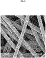
Fig. 1 zeigt eine REM(Rasterelektronen-Mikroskopie)-Aufnahme der Oberfläche einer kommerziellen Nickel-Sinterelektrode bei 1000-facher Vergrößerung. (aus Morioka Y., Narukawa S., Itou T., Journal of Power Sources 100 (2001): 107-116); -
Fig. 2 zeigt eine REM-Aufnahme der Oberfläche einer kommerziellen Nickel-Schaumelektrode mit wabenartiger Struktur bei 150-facher Vergrößerung; -
Fig. 3 zeigt eine REM-Aufnahme der Oberfläche einer kommerziellen Nickel-Faserelektrode bei 500-facher Vergrößerung. (aus Ohms D., Kohlhase M., Benczur-Urmossy G., Schadlich G., Journal of Power Sources 105 (2002): 127-133); -
Fig. 4 zeigt eine REM-Aufnahme der Oberfläche einer erfindungsgemäßen Nickelelektrode 500-facher Vergrößerung; -
Fig. 5 zeigt eine REM-Aufnahme der Oberfläche einer erfindungsgemäßen Nickelelektrode bei 10.000-facher Vergrößerung; -
Fig. 6a zeigt ein quasistationäres Zyklovoltammogramm mit einer Scanrate von 50 µV s-1 an einer erfindungsgemäßen 1 cm2-Nickelelektrode zur Wasserelektrolyse in einem Elektrolyten aus 5,5M KOH; 2,5M NaOH und 0,5M LiOH bei Raumtemperatur. Die Rückseite der Elektrode ist elektrisch isolierend mit Epoxidharz beschichtet; -
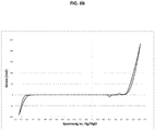
Fig. 6b zeigt ein quasistationäres Zyklovoltammogramm mit einer Scanrate von 100 µV s-1 an einer erfindungsgemäßen 1 cm2-Nickelelektrode zur Wasserelektrolyse in einem Elektrolyten aus 5,5M KOH; 2,5M NaOH und 0,5M LiOH bei Raumtemperatur. Die Rückseite der Elektrode ist elektrisch isolierend mit Epoxidharz beschichtet; -
Fig. 6c zeigt ein quasistationäres Zyklovoltammogramm mit einer Scanrate von 50 µV s-1 an einer planen und unbehandelten 1 cm2-Nickelelektrode zur Wasserelektrolyse in einem Elektrolyten aus 5,5M KOH; 2,5M NaOH und 0,5M LiOH bei Raumtemperatur. Die Rückseite der Elektrode ist elektrisch isolierend mit Epoxidharz beschichtet; -
Fig. 6d zeigt ein quasistationäres Zyklovoltammogramm mit einer Scanrate von 100 µV s-1 an einer planen und unbehandelten 1 cm2-Nickelelektrode zur Wasserelektrolyse in einem Elektrolyten aus 5,5M KOH; 2,5M NaOH und 0,5M LiOH bei Raumtemperatur. Die Rückseite der Elektrode ist elektrisch isolierend mit Epoxidharz beschichtet. - 50 g sphärische β-Ni(OH)2-Partikel werden bei einer Temperatur von 300 °C für 4 Stunden in einer Atmosphäre aus 50 Vol.% Wasserstoff in Stickstoff in einem Glühofen partiell reduziert, wobei der durchschnittliche Partikeldurchmesser von etwa 10 µm erhalten blieb. Diese partiell reduzierten, sphärischen Ni/NiO-Partikel weisen bereits eine innere Porenstruktur auf.
5 g der partiell reduzierten, sphärischen Ni/NiO-Partikel werden mit 3 ml einer 7,5 Gew.-% wässrigen Polyvinylalkohollösung zu einer Paste angeteigt, die anschließend einseitig auf 125 µm Nickelblech beschichtet wird. - Nach einer abschließenden Temperung im Glühofen bei einer Temperatur von 620 °C in einer reduzierenden Atmosphäre aus 50 Vol.% Wasserstoff in Stickstoff ist die gebildete Elektrode einsetzbar. Die sphärischen Nickelpartikel, die auf dem Nickelblech aufgebracht wurden, haben einen durchschnittlichen Durchmesser von 3,4 µm und weisen eine innere Porenstruktur auf.
- In der nachfolgenden Tabelle 1 sind die mittleren Partikelgrößen der eingesetzten Nickelhydroxid-Partikel, der partiell reduzierten Ni/NiO-Partikel sowie der sphärischen, porösen Nickelpartikel der Nickelschicht zusammengefasst.
Tabelle 1 Probe Mittlere Partikelgröße [µm] β-Ni(OH)2 10,1 Partiell reduziertes Ni/NiO 10,3 Ni-Partikel auf Ni-Blech beschichtet 3,4 - Aufgrund der hohen inneren Oberfläche ist der Übergangswiderstand der erfindungsgemäßen Elektrode zum umgebenen Medium sehr gering und damit die erreichbare Stromdichte z.B. in der Wasserhydrolyse größer als im Vergleich zu unbeschichteten Nickelblechen. In unbeschichteten Nickelblechen werden Stromdichten im Bereich von 144 mA/cm2 bei einer Spannung von 0,819 V gegenüber der Hg/HgO-Referenzelektrode und Spannungsänderungen im Bereich von 50 bis 100 µV/s in einem Elektrolyten aus 5,5M KOH, 2,5M NaOH und 0,5M LiOH erhalten. Die geringe Spannungsänderung kann als quasistatische Messung betrachtet werden. Das gewählte Potential von 0,819 V gegenüber der Hg/HgO-Referenz ist alleinig der Sauerstoffentwicklung zuzurechnen. Bei nach dem erfindungsgemäßen Verfahren hergestellten oberflächenreichen Nickelelektroden werden unter den gleichen Bedingungen Stromdichten von zwischen 218-232 mA/cm2 gefunden. Das entspricht einer mittleren Verstärkung der Stromdichte um einen Faktor von etwa 1,5 (siehe Tab.2). Die entsprechenden Zyklovoltammogramme sind in
Fig. 6 a-d zu finden.Tabelle 2 Probe Stromdichte [mA/cm2] bei 50 µV/s Stromdichte [mA/cm2] bei 100 µV/s Ni-Blech unbeschichtet; Rückseite mit Epoxidharz abgedeckt 144,65 144,81 Ni-Blech mit 3,4 µm Ni-Partikeln beschichtet; Rückseite mit Epoxidharz abgedeckt 218,67 232,81 Mittlerer Verstärkungsfaktor 1.5 1.6 - Einen wesentlich größeren Effekt der Verstärkung der Gasentwicklung durch die erfindungsgemäßen oberflächenreichen Nickelelektroden ist für die Wasserstoffentwicklung zu beobachten. In unbeschichteten Nickelblechen werden Stromdichten im Bereich von 5 mA/cm2 bei einer Spannung von -1,231 V gegenüber der Hg/HgO-Referenzelektrode und einer Spannungsänderung von 50 bis 100 µV/s in einem Elektrolyten aus 5,5M KOH, 2,5M NaOH und 0,5M LiOH erhalten. Die geringe Spannungsänderung kann als quasistatische Messung betrachtet werden. Das gewählte Potential von -1,231 V gegenüber der Hg/HgO-Referenz ist alleinig der Wasserstoffentwicklung zuzurechnen. Bei nach dem erfindungsgemäßen Verfahren hergestellten oberflächenreichen Nickelelektroden werden unter den gleichen Bedingungen Stromdichten von zwischen 86-91 mA/cm2 gefunden. Das entspricht einer mittleren Verstärkung der Stromdichte um einen Faktor von etwa 17 (siehe Tab.3). Die entsprechenden Zyklovoltammogramme sind in
Fig. 6 a-d zu finden.Tabelle 3 Probe Stromdichte [mA/cm2] bei 50 µV/s Stromdichte [mA/cm2] bei 100 µV/s Ni-Blech unbeschichtet; Rückseite mit Epoxidharz abgedeckt 5,35 4,92 Ni-Blech mit 3,4 µm Ni-Partikeln beschichtet; Rückseite mit Epoxidharz abgedeckt 86,49 91,29 Mittlerer Verstärkungsfaktor 16,2 18,55
Claims (12)
- Nickelelektrode, umfassend ein elektrisch leitfähiges Nickelblech und eine darauf aufgebrachte Nickelschicht aus aneinander haftenden, sphärischen, porösen Nickelpartikeln mit einer mittleren Partikelgröße von 0,1 - 25 µm, die eine innere Porenstruktur und somit eine innere Oberfläche aufweisen, erhältlich durch ein Verfahren, umfassend folgende Schritte:a) Vorsehen von sphärischen Nickelhydroxid-Partikeln,b) partielle Reduzierung der sphärischen Nickelhydroxid-Partikel in einer reduzierenden Atmosphäre bei Temperaturen von 270-330°C zur Erzielung partiell reduzierter, sphärischer Ni/NiO-Partikel,c) Herstellen einer Paste aus den erhaltenen Ni/NiO-Partikeln und einem organischen und/oder anorganischen Bindemittel sowie ggf. weiteren Hilfsstoffen,d) Aufbeschichten der Paste auf eine oder beide Seiten des elektrisch leitfähigen Nickelblechs, unde) Tempern des beschichteten Nickelblechs in einer reduzierenden Atmosphäre bei Temperaturen von 500-800°C.
- Freitragende Nickelschicht aus aneinander haftenden, sphärischen, porösen Nickelpartikeln, die eine innere Porenstruktur und somit eine innere Oberfläche aufweisen, erhältlich durch ein Verfahren, umfassend folgende Schritte:a) Vorsehen von sphärischen Nickelhydroxid-Partikelnb) partielle Reduzierung der sphärischen Nickelhydroxid-Partikel in einer reduzierenden Atmosphäre bei Temperaturen von 270-330°C zur Erzielung partiell reduzierter, sphärischer Ni/NiO-Partikel,c) Herstellen einer Paste aus den erhaltenen Ni/NiO-Partikeln und einem organischen und/oder anorganischen Bindemittel sowie ggf. weiteren Hilfsstoffen,d) Aufbeschichten der Paste auf einen Träger,e) Tempern des beschichteten Trägers in einer reduzierenden Atmosphäre bei Temperaturen von 500-800°C, undf) Abtrennen des Trägers zur Erzielung der freitragenden porösen Nickelschicht.
- Nickelelektrode oder freitragende Nickelschicht nach Anspruch 1 oder 2, wobei die im Schritt a) vorgesehenen sphärischen Nickelhydroxid-Partikel eine mittlere Partikelgröße von 0,3-75 µm, vorzugsweise 3-30 µm, weiter vorzugsweise 9-12 µm, insbesondere bevorzugt 10 µm, aufweisen.
- Nickelelektrode oder freitragende Nickelschicht nach mindestens einem der vorangehenden Ansprüche, wobei die partielle Reduzierung im Schritt b) bei Temperaturen von 290 - 310 °C, durchgeführt wird.
- Nickelelektrode oder freitragende Nickelschicht nach mindestens einem der vorangehenden Ansprüche, wobei die partielle Reduzierung im Schritt b) und die Temperung im Schritt e) in einer reduzierenden Atmosphäre, umfassend 10 - 100 % Wasserstoff und gegebenenfalls ein Inertgas, durchgeführt wird.
- Nickelelektrode oder freitragende Nickelschicht nach mindestens einem der vorangehenden Ansprüche, wobei im Schritt c) als organische Bindemittel natürliche und/oder synthetische Polymere oder Derivate davon, und als anorganische Bindemittel Ammoniumsalze oder Hydrazinsalze eingesetzt werden.
- Nickelelektrode oder freitragende Nickelschicht nach mindestens einem der vorangehenden Ansprüche, wobei die Nickelschicht der Nickelelektrode oder die freitragende Nickelschicht eine Dicke im Bereich von 1-1.000 µm, vorzugsweise 10-900 µm, weiter vorzugsweise 20-200 µm, aufweist.
- Nickelelektrode oder freitragende Nickelschicht nach mindestens einem der vorangehenden Ansprüche, wobei die sphärischen, porösen Nickelpartikel eine mittlere Partikelgröße von 0,1-25 µm, vorzugsweise 1-10 µm, weiter vorzugsweise 2 - 6 µm, insbesondere bevorzugt 3-4 µm, aufweisen.
- Verfahren zur Herstellung einer Nickelelektrode gemäß mindestens einem der Ansprüche 1 bis 8, umfassend folgende Schritte:a) Vorsehen von sphärischen Nickelhydroxid-Partikeln,b) partielle Reduzierung der sphärischen Nickelhydroxid-Partikel in einer reduzierenden Atmosphäre bei Temperaturen von 270-330°C zur Erzielung partiell reduzierter, sphärischer Ni/NiO-Partikel,c) Herstellen einer Paste aus den erhaltenen Ni/NiO-Partikeln und einem organischen und/oder anorganischen Bindemittel sowie ggf. weiteren Hilfsstoffen,d) Aufbeschichten der Paste auf eine oder beide Seiten des elektrisch leitfähigen Nickelblechs, unde) Tempern des beschichteten Nickelblechs in einer reduzierenden Atmosphäre bei Temperaturen von 500-800°C.
- Verfahren zur Herstellung einer freitragenden Nickelschicht nach mindestens einem der Ansprüche 2 bis 8, umfassend folgende Schritte:a) Vorsehen von sphärischen Nickelhydroxid-Partikelnb) partielle Reduzierung der sphärischen Nickelhydroxid-Partikel in einer reduzierenden Atmosphäre bei Temperaturen von 270-330°C zur Erzielung partiell reduzierter, sphärischer Ni/NiO-Partikel,c) Herstellen einer Paste aus den erhaltenen Ni/NiO-Partikeln und einem organischen und/oder anorganischen Bindemittel sowie ggf. weiteren Hilfsstoffen,d) Aufbeschichten der Paste auf einen Träger,e) Tempern des beschichteten Trägers in einer reduzierenden Atmosphäre bei Temperaturen von 500-800°C, undf) Abtrennen des Trägers zur Erzielung der freitragenden porösen Nickelschicht.
- Verwendung der Nickelelektrode nach mindestens einem der Ansprüche 1 bis 8 als Arbeitselektrode in Batterien, Akkumulatoren, symmetrischen und asymmetrischen Doppelschichtkondensatoren, Sensoren, als Katalysatorträger, als Elektroden in elektrochemischen Synthesen oder in fotoelektrischen und fotokatalytischen Geräten, insbesondere für die Wasserelektrolyse in einem alkalischen Medium.
- Verwendung der freitragenden Nickelschicht nach mindestens einem der Ansprüche 2 bis 8 als Elektrode für die Wasserelektrolyse.
Applications Claiming Priority (2)
| Application Number | Priority Date | Filing Date | Title |
|---|---|---|---|
| DE102015120057.0A DE102015120057A1 (de) | 2015-11-19 | 2015-11-19 | Nickelelektrode, freitragende Nickelschicht, Verfahren zu deren Herstellung und deren Verwendung |
| PCT/EP2016/077978 WO2017085173A1 (de) | 2015-11-19 | 2016-11-17 | Nickelelektrode, freitragende nickelschicht, verfahren zu deren herstellung und deren verwendung |
Publications (2)
| Publication Number | Publication Date |
|---|---|
| EP3194639A1 EP3194639A1 (de) | 2017-07-26 |
| EP3194639B1 true EP3194639B1 (de) | 2019-03-13 |
Family
ID=57345945
Family Applications (1)
| Application Number | Title | Priority Date | Filing Date |
|---|---|---|---|
| EP16797904.6A Active EP3194639B1 (de) | 2015-11-19 | 2016-11-17 | Nickelelektrode, freitragende nickelschicht, verfahren zu deren herstellung und deren verwendung |
Country Status (6)
| Country | Link |
|---|---|
| US (1) | US10829860B2 (de) |
| EP (1) | EP3194639B1 (de) |
| JP (1) | JP6722282B2 (de) |
| CN (1) | CN108291319B (de) |
| DE (1) | DE102015120057A1 (de) |
| WO (1) | WO2017085173A1 (de) |
Families Citing this family (10)
| Publication number | Priority date | Publication date | Assignee | Title |
|---|---|---|---|---|
| DE102017110863B4 (de) | 2017-05-18 | 2021-02-04 | Zentrum für Sonnenenergie- und Wasserstoff-Forschung Baden-Württemberg | Nickelelektrode, Verfahren zu deren Herstellung und deren Verwendung |
| KR102084430B1 (ko) * | 2018-10-30 | 2020-03-04 | 인하대학교 산학협력단 | 산소발생용 니켈 수산화물 촉매의 산소결핍의 유도 방법 및 이에 의해 제조된 니켈 수산화물 촉매 |
| DE102018131168A1 (de) * | 2018-12-06 | 2020-06-10 | Zentrum für Sonnenenergie- und Wasserstoff-Forschung Baden-Württemberg Gemeinnützige Stiftung | Reversible Mangandioxidelektrode, Verfahren zu deren Herstellung, deren Verwendung sowie diese enthaltende, wieder aufladbare alkalische Mangan-Batterie |
| CN109841810B (zh) * | 2019-01-07 | 2020-12-15 | 浙江工业大学 | 一种Ni-NiO/C复合材料的制备方法及应用 |
| JP2021070863A (ja) * | 2019-11-01 | 2021-05-06 | 東洋アルミニウム株式会社 | アルカリ水電解用電極 |
| CN110863213B (zh) * | 2019-12-02 | 2022-01-11 | 东北石油大学 | 一种提高镍电极在熔盐体系中耐腐蚀性的方法 |
| IT202000020575A1 (it) * | 2020-08-28 | 2022-02-28 | Industrie De Nora Spa | Elettrodo per l'evoluzione del gas nei processi elettrolitici |
| EP4060081A1 (de) * | 2021-03-16 | 2022-09-21 | Industrie De Nora S.P.A. | Elektrode zur gasentwicklung in elektrolytischen prozessen |
| CN114188163B (zh) * | 2021-12-08 | 2023-01-24 | 吉林大学 | 一种NiO毛线球形电极材料及其制备方法和应用 |
| CN114446670B (zh) * | 2022-03-01 | 2024-05-24 | 石河子大学 | 一种以甘草药渣多孔碳为基底的镍钴水滑石复合材料及其制备方法与应用 |
Citations (2)
| Publication number | Priority date | Publication date | Assignee | Title |
|---|---|---|---|---|
| US20020150821A1 (en) * | 2001-01-31 | 2002-10-17 | Sanyo Electric Co., Ltd. | Manufacturing method for sintered substrate of alkaline storage battery |
| DE69911150T2 (de) * | 1998-12-02 | 2004-07-29 | Katayama Special Industries, Ltd. | Verfahren zur Herstellung von Elektroden einer Batterie und durch Verfahren hergestellte Elektrode |
Family Cites Families (14)
| Publication number | Priority date | Publication date | Assignee | Title |
|---|---|---|---|---|
| DE2002298C3 (de) | 1970-01-20 | 1974-05-30 | Guenter Dipl.-Chem. 4134 Rheinberg Barthel | Verfahren zur Herstellung von Elektroden für die technische Wasserelektrolyse |
| JPS572886A (en) * | 1980-06-05 | 1982-01-08 | Agency Of Ind Science & Technol | Production of electrode |
| AU565812B2 (en) | 1982-11-30 | 1987-10-01 | Asahi Kasei Kogyo Kabushiki Kaisha | An improved hydrogen-evolution electrode and a method of producing the same |
| JPS6286186A (ja) | 1985-10-11 | 1987-04-20 | Asahi Chem Ind Co Ltd | 活性陰極のサ−ビスライフ延長方法 |
| DE3612790A1 (de) | 1986-04-16 | 1987-10-22 | Sigri Gmbh | Kathode fuer waesserige elektrolysen |
| JPH0375392A (ja) * | 1989-08-18 | 1991-03-29 | Asahi Chem Ind Co Ltd | 水素発生用電極 |
| JPH03166393A (ja) | 1989-08-23 | 1991-07-18 | Asahi Chem Ind Co Ltd | 水素発生用の電極 |
| US5851599A (en) | 1995-09-28 | 1998-12-22 | Sumitomo Electric Industries Co., Ltd. | Battery electrode substrate and process for producing the same |
| JPH10310806A (ja) * | 1997-03-11 | 1998-11-24 | Katayama Tokushu Kogyo Kk | 金属多孔体の製造方法、該方法により製造された金属多孔体及び電池用電極 |
| DE10045912C2 (de) * | 2000-09-16 | 2002-08-01 | Mtu Friedrichshafen Gmbh | Verfahren zur Herstellung einer Schmelzcarbonat-Brennstoffzelle sowie Schmelzcarbonat-Brennstoffzelle |
| JP2003328007A (ja) | 2002-05-13 | 2003-11-19 | Ishikawajima Harima Heavy Ind Co Ltd | Ni多孔体の製造方法 |
| CN101857279A (zh) * | 2010-06-29 | 2010-10-13 | 上海大学 | 用于碳钢表面合金化的纳米氧化镍粉体的制备方法 |
| DK2862960T3 (da) | 2012-06-18 | 2020-03-23 | Asahi Chemical Ind | Bipolær alkalisk vandelektrolyseenhed |
| CN104269278B (zh) * | 2014-10-08 | 2017-06-27 | 河北工业大学 | 一种自立式纳米多孔镍/氧化镍复合电极片及其制备方法 |
-
2015
- 2015-11-19 DE DE102015120057.0A patent/DE102015120057A1/de not_active Ceased
-
2016
- 2016-11-17 EP EP16797904.6A patent/EP3194639B1/de active Active
- 2016-11-17 CN CN201680066843.9A patent/CN108291319B/zh active Active
- 2016-11-17 WO PCT/EP2016/077978 patent/WO2017085173A1/de not_active Ceased
- 2016-11-17 JP JP2018520196A patent/JP6722282B2/ja active Active
- 2016-11-17 US US15/775,209 patent/US10829860B2/en active Active
Patent Citations (2)
| Publication number | Priority date | Publication date | Assignee | Title |
|---|---|---|---|---|
| DE69911150T2 (de) * | 1998-12-02 | 2004-07-29 | Katayama Special Industries, Ltd. | Verfahren zur Herstellung von Elektroden einer Batterie und durch Verfahren hergestellte Elektrode |
| US20020150821A1 (en) * | 2001-01-31 | 2002-10-17 | Sanyo Electric Co., Ltd. | Manufacturing method for sintered substrate of alkaline storage battery |
Also Published As
| Publication number | Publication date |
|---|---|
| CN108291319A (zh) | 2018-07-17 |
| US20180355493A1 (en) | 2018-12-13 |
| CN108291319B (zh) | 2021-04-09 |
| JP6722282B2 (ja) | 2020-07-15 |
| WO2017085173A1 (de) | 2017-05-26 |
| US10829860B2 (en) | 2020-11-10 |
| EP3194639A1 (de) | 2017-07-26 |
| JP2018538432A (ja) | 2018-12-27 |
| DE102015120057A1 (de) | 2017-05-24 |
Similar Documents
| Publication | Publication Date | Title |
|---|---|---|
| DE102015120057A1 (de) | Nickelelektrode, freitragende Nickelschicht, Verfahren zu deren Herstellung und deren Verwendung | |
| EP3625379B1 (de) | Nickelelektrode, verfahren zu deren herstellung und deren verwendung | |
| DE112010001642B4 (de) | Verfahren zum herstellen eines materials auf titanbasis | |
| KR101610354B1 (ko) | 전착법을 이용한 금속산화물이 담지된 탄소나노섬유 전극 제조방법 및 이를 이용한 에너지 저장장치 및 필터 | |
| DE102015120879A1 (de) | Verfahren zum Herstellen einer Silizium-basierten porösen Elektrode für eine Batterie, insbesondere Lithium-Ionen-Batterie | |
| DE102009027174A1 (de) | Substrat zur Verwendung bei einem Nass-Elektrolytkondensator | |
| JP6048467B2 (ja) | 纎維状ペロブスカイト型酸化物触媒の製造方法 | |
| WO2016070862A1 (de) | Bipolarplatte für elektrochemische zellen sowie verfahren zur herstellung derselben | |
| DE112012000877T5 (de) | Poröser Aluminiumkörper mit dreidimensionalem Netzwerk für einen Stromkollektor, Elektrode, die den porösen Aluminiumkörper verwendet, und Batterie mit nicht-wässrigem Elektrolyt, Kondensator und Lithium-Ionen-Kondensator mit nicht-wässriger elektrolytischer Lösung, die die Elektrode verwenden | |
| EP4347923A1 (de) | Elektrolysezelle zur polymerelektrolytmembran-elektrolyse und verfahren zu deren herstellung | |
| DE102012112186A1 (de) | Materialverbund, Verfahren zu dessen Herstellung, daraus hergestelltes System und Anwendung desselben | |
| KR101391136B1 (ko) | 그라파이트에 금속 산화물이 전착된 슈퍼커패시터 전극의 제조방법 및 이를 이용한 슈퍼커패시터 | |
| DE102006050090B4 (de) | Sauerstoff-Reduktions-Gasdiffusionskathode und Verfahren zur Durchführung einer Natriumchlorid-Elektrolyse in einer Elektrolysezelle | |
| Zhang et al. | Enlarged capacitance of TiO2 nanotube array electrodes treated by water soaking | |
| JP2024516075A (ja) | 電解プロセスにおけるガス発生のための電極 | |
| KR101813405B1 (ko) | 바나듐 레독스 플로우 배터리용 이리듐 산화물이 코팅된 타이타늄 기반 바이폴라 플레이트 및 이의 제조방법 | |
| DE102013213740A1 (de) | Verfahren zur Herstellung von transport- und lagerstabilen Sauerstoffverzehrelektroden | |
| DE102010003294B4 (de) | Elektrode aus einem elektrisch leitenden Verbundwerkstoff und Verfahren zur Herstellung | |
| DE102022115040A1 (de) | Bifunktionale Gasdiffusionselektrode für alkalische elektrochemische Energiewandlersysteme und Verfahren zu deren Herstellung | |
| DE102016112125B4 (de) | Verfahren zur Herstellung eines Festelektrolyts | |
| DE102012020344A1 (de) | Polymerelektrolytmembran mit MnO2-Nanopartikeln | |
| WO2014111228A1 (de) | Verfahren zur herstellung einer elektroden-elektrolyt-einheit für einen wiederaufladbaren elektrischen energiespeicher, insbesondere einen metalloxid-luft-energiespeicher, mit einem zwischen zwei elektroden angeordneten elektrolyten |
Legal Events
| Date | Code | Title | Description |
|---|---|---|---|
| STAA | Information on the status of an ep patent application or granted ep patent |
Free format text: STATUS: UNKNOWN |
|
| STAA | Information on the status of an ep patent application or granted ep patent |
Free format text: STATUS: THE INTERNATIONAL PUBLICATION HAS BEEN MADE |
|
| PUAI | Public reference made under article 153(3) epc to a published international application that has entered the european phase |
Free format text: ORIGINAL CODE: 0009012 |
|
| STAA | Information on the status of an ep patent application or granted ep patent |
Free format text: STATUS: REQUEST FOR EXAMINATION WAS MADE |
|
| 17P | Request for examination filed |
Effective date: 20170202 |
|
| AK | Designated contracting states |
Kind code of ref document: A1 Designated state(s): AL AT BE BG CH CY CZ DE DK EE ES FI FR GB GR HR HU IE IS IT LI LT LU LV MC MK MT NL NO PL PT RO RS SE SI SK SM TR |
|
| AX | Request for extension of the european patent |
Extension state: BA ME |
|
| STAA | Information on the status of an ep patent application or granted ep patent |
Free format text: STATUS: EXAMINATION IS IN PROGRESS |
|
| 17Q | First examination report despatched |
Effective date: 20180321 |
|
| REG | Reference to a national code |
Ref country code: DE Ref legal event code: R079 Ref document number: 502016003775 Country of ref document: DE Free format text: PREVIOUS MAIN CLASS: C25B0011030000 Ipc: C25B0001040000 |
|
| RIN1 | Information on inventor provided before grant (corrected) |
Inventor name: ASANTE, JERRY BAMFO Inventor name: BOESE, OLAF Inventor name: JOERISSEN, LUDWIG |
|
| GRAP | Despatch of communication of intention to grant a patent |
Free format text: ORIGINAL CODE: EPIDOSNIGR1 |
|
| STAA | Information on the status of an ep patent application or granted ep patent |
Free format text: STATUS: GRANT OF PATENT IS INTENDED |
|
| RIC1 | Information provided on ipc code assigned before grant |
Ipc: B01J 35/00 20060101ALI20181005BHEP Ipc: H01M 4/80 20060101ALI20181005BHEP Ipc: C25B 11/03 20060101ALI20181005BHEP Ipc: H01L 49/02 20060101ALI20181005BHEP Ipc: H01L 31/0224 20060101ALI20181005BHEP Ipc: C25B 11/04 20060101ALI20181005BHEP Ipc: B01J 23/755 20060101ALI20181005BHEP Ipc: H01M 4/66 20060101ALI20181005BHEP Ipc: C02F 1/461 20060101ALI20181005BHEP Ipc: C25B 1/04 20060101AFI20181005BHEP Ipc: B01J 35/08 20060101ALI20181005BHEP Ipc: C25B 1/34 20060101ALI20181005BHEP |
|
| DAV | Request for validation of the european patent (deleted) | ||
| DAX | Request for extension of the european patent (deleted) | ||
| INTG | Intention to grant announced |
Effective date: 20181105 |
|
| GRAS | Grant fee paid |
Free format text: ORIGINAL CODE: EPIDOSNIGR3 |
|
| GRAA | (expected) grant |
Free format text: ORIGINAL CODE: 0009210 |
|
| STAA | Information on the status of an ep patent application or granted ep patent |
Free format text: STATUS: THE PATENT HAS BEEN GRANTED |
|
| AK | Designated contracting states |
Kind code of ref document: B1 Designated state(s): AL AT BE BG CH CY CZ DE DK EE ES FI FR GB GR HR HU IE IS IT LI LT LU LV MC MK MT NL NO PL PT RO RS SE SI SK SM TR |
|
| REG | Reference to a national code |
Ref country code: GB Ref legal event code: FG4D Free format text: NOT ENGLISH |
|
| REG | Reference to a national code |
Ref country code: CH Ref legal event code: EP Ref country code: AT Ref legal event code: REF Ref document number: 1107764 Country of ref document: AT Kind code of ref document: T Effective date: 20190315 |
|
| REG | Reference to a national code |
Ref country code: IE Ref legal event code: FG4D Free format text: LANGUAGE OF EP DOCUMENT: GERMAN |
|
| REG | Reference to a national code |
Ref country code: DE Ref legal event code: R096 Ref document number: 502016003775 Country of ref document: DE |
|
| RAP2 | Party data changed (patent owner data changed or rights of a patent transferred) |
Owner name: ZENTRUM FUER SONNENENERGIE- UND WASSERSTOFF-FORSCH |
|
| REG | Reference to a national code |
Ref country code: NL Ref legal event code: MP Effective date: 20190313 |
|
| REG | Reference to a national code |
Ref country code: LT Ref legal event code: MG4D |
|
| PG25 | Lapsed in a contracting state [announced via postgrant information from national office to epo] |
Ref country code: FI Free format text: LAPSE BECAUSE OF FAILURE TO SUBMIT A TRANSLATION OF THE DESCRIPTION OR TO PAY THE FEE WITHIN THE PRESCRIBED TIME-LIMIT Effective date: 20190313 Ref country code: SE Free format text: LAPSE BECAUSE OF FAILURE TO SUBMIT A TRANSLATION OF THE DESCRIPTION OR TO PAY THE FEE WITHIN THE PRESCRIBED TIME-LIMIT Effective date: 20190313 Ref country code: LT Free format text: LAPSE BECAUSE OF FAILURE TO SUBMIT A TRANSLATION OF THE DESCRIPTION OR TO PAY THE FEE WITHIN THE PRESCRIBED TIME-LIMIT Effective date: 20190313 |
|
| PG25 | Lapsed in a contracting state [announced via postgrant information from national office to epo] |
Ref country code: HR Free format text: LAPSE BECAUSE OF FAILURE TO SUBMIT A TRANSLATION OF THE DESCRIPTION OR TO PAY THE FEE WITHIN THE PRESCRIBED TIME-LIMIT Effective date: 20190313 Ref country code: NL Free format text: LAPSE BECAUSE OF FAILURE TO SUBMIT A TRANSLATION OF THE DESCRIPTION OR TO PAY THE FEE WITHIN THE PRESCRIBED TIME-LIMIT Effective date: 20190313 Ref country code: RS Free format text: LAPSE BECAUSE OF FAILURE TO SUBMIT A TRANSLATION OF THE DESCRIPTION OR TO PAY THE FEE WITHIN THE PRESCRIBED TIME-LIMIT Effective date: 20190313 Ref country code: GR Free format text: LAPSE BECAUSE OF FAILURE TO SUBMIT A TRANSLATION OF THE DESCRIPTION OR TO PAY THE FEE WITHIN THE PRESCRIBED TIME-LIMIT Effective date: 20190614 Ref country code: LV Free format text: LAPSE BECAUSE OF FAILURE TO SUBMIT A TRANSLATION OF THE DESCRIPTION OR TO PAY THE FEE WITHIN THE PRESCRIBED TIME-LIMIT Effective date: 20190313 Ref country code: BG Free format text: LAPSE BECAUSE OF FAILURE TO SUBMIT A TRANSLATION OF THE DESCRIPTION OR TO PAY THE FEE WITHIN THE PRESCRIBED TIME-LIMIT Effective date: 20190613 |
|
| REG | Reference to a national code |
Ref country code: NO Ref legal event code: T2 Effective date: 20190313 |
|
| PG25 | Lapsed in a contracting state [announced via postgrant information from national office to epo] |
Ref country code: EE Free format text: LAPSE BECAUSE OF FAILURE TO SUBMIT A TRANSLATION OF THE DESCRIPTION OR TO PAY THE FEE WITHIN THE PRESCRIBED TIME-LIMIT Effective date: 20190313 Ref country code: RO Free format text: LAPSE BECAUSE OF FAILURE TO SUBMIT A TRANSLATION OF THE DESCRIPTION OR TO PAY THE FEE WITHIN THE PRESCRIBED TIME-LIMIT Effective date: 20190313 Ref country code: CZ Free format text: LAPSE BECAUSE OF FAILURE TO SUBMIT A TRANSLATION OF THE DESCRIPTION OR TO PAY THE FEE WITHIN THE PRESCRIBED TIME-LIMIT Effective date: 20190313 Ref country code: ES Free format text: LAPSE BECAUSE OF FAILURE TO SUBMIT A TRANSLATION OF THE DESCRIPTION OR TO PAY THE FEE WITHIN THE PRESCRIBED TIME-LIMIT Effective date: 20190313 Ref country code: AL Free format text: LAPSE BECAUSE OF FAILURE TO SUBMIT A TRANSLATION OF THE DESCRIPTION OR TO PAY THE FEE WITHIN THE PRESCRIBED TIME-LIMIT Effective date: 20190313 Ref country code: SK Free format text: LAPSE BECAUSE OF FAILURE TO SUBMIT A TRANSLATION OF THE DESCRIPTION OR TO PAY THE FEE WITHIN THE PRESCRIBED TIME-LIMIT Effective date: 20190313 Ref country code: IT Free format text: LAPSE BECAUSE OF FAILURE TO SUBMIT A TRANSLATION OF THE DESCRIPTION OR TO PAY THE FEE WITHIN THE PRESCRIBED TIME-LIMIT Effective date: 20190313 Ref country code: PT Free format text: LAPSE BECAUSE OF FAILURE TO SUBMIT A TRANSLATION OF THE DESCRIPTION OR TO PAY THE FEE WITHIN THE PRESCRIBED TIME-LIMIT Effective date: 20190713 |
|
| PG25 | Lapsed in a contracting state [announced via postgrant information from national office to epo] |
Ref country code: PL Free format text: LAPSE BECAUSE OF FAILURE TO SUBMIT A TRANSLATION OF THE DESCRIPTION OR TO PAY THE FEE WITHIN THE PRESCRIBED TIME-LIMIT Effective date: 20190313 Ref country code: SM Free format text: LAPSE BECAUSE OF FAILURE TO SUBMIT A TRANSLATION OF THE DESCRIPTION OR TO PAY THE FEE WITHIN THE PRESCRIBED TIME-LIMIT Effective date: 20190313 |
|
| REG | Reference to a national code |
Ref country code: DE Ref legal event code: R097 Ref document number: 502016003775 Country of ref document: DE |
|
| PG25 | Lapsed in a contracting state [announced via postgrant information from national office to epo] |
Ref country code: IS Free format text: LAPSE BECAUSE OF FAILURE TO SUBMIT A TRANSLATION OF THE DESCRIPTION OR TO PAY THE FEE WITHIN THE PRESCRIBED TIME-LIMIT Effective date: 20190713 |
|
| PLBE | No opposition filed within time limit |
Free format text: ORIGINAL CODE: 0009261 |
|
| STAA | Information on the status of an ep patent application or granted ep patent |
Free format text: STATUS: NO OPPOSITION FILED WITHIN TIME LIMIT |
|
| PG25 | Lapsed in a contracting state [announced via postgrant information from national office to epo] |
Ref country code: DK Free format text: LAPSE BECAUSE OF FAILURE TO SUBMIT A TRANSLATION OF THE DESCRIPTION OR TO PAY THE FEE WITHIN THE PRESCRIBED TIME-LIMIT Effective date: 20190313 |
|
| 26N | No opposition filed |
Effective date: 20191216 |
|
| PG25 | Lapsed in a contracting state [announced via postgrant information from national office to epo] |
Ref country code: SI Free format text: LAPSE BECAUSE OF FAILURE TO SUBMIT A TRANSLATION OF THE DESCRIPTION OR TO PAY THE FEE WITHIN THE PRESCRIBED TIME-LIMIT Effective date: 20190313 |
|
| PG25 | Lapsed in a contracting state [announced via postgrant information from national office to epo] |
Ref country code: TR Free format text: LAPSE BECAUSE OF FAILURE TO SUBMIT A TRANSLATION OF THE DESCRIPTION OR TO PAY THE FEE WITHIN THE PRESCRIBED TIME-LIMIT Effective date: 20190313 |
|
| REG | Reference to a national code |
Ref country code: CH Ref legal event code: PL |
|
| PG25 | Lapsed in a contracting state [announced via postgrant information from national office to epo] |
Ref country code: MC Free format text: LAPSE BECAUSE OF FAILURE TO SUBMIT A TRANSLATION OF THE DESCRIPTION OR TO PAY THE FEE WITHIN THE PRESCRIBED TIME-LIMIT Effective date: 20190313 Ref country code: CH Free format text: LAPSE BECAUSE OF NON-PAYMENT OF DUE FEES Effective date: 20191130 Ref country code: LI Free format text: LAPSE BECAUSE OF NON-PAYMENT OF DUE FEES Effective date: 20191130 Ref country code: LU Free format text: LAPSE BECAUSE OF NON-PAYMENT OF DUE FEES Effective date: 20191117 |
|
| REG | Reference to a national code |
Ref country code: BE Ref legal event code: MM Effective date: 20191130 |
|
| PG25 | Lapsed in a contracting state [announced via postgrant information from national office to epo] |
Ref country code: IE Free format text: LAPSE BECAUSE OF NON-PAYMENT OF DUE FEES Effective date: 20191117 |
|
| PG25 | Lapsed in a contracting state [announced via postgrant information from national office to epo] |
Ref country code: BE Free format text: LAPSE BECAUSE OF NON-PAYMENT OF DUE FEES Effective date: 20191130 |
|
| PG25 | Lapsed in a contracting state [announced via postgrant information from national office to epo] |
Ref country code: CY Free format text: LAPSE BECAUSE OF FAILURE TO SUBMIT A TRANSLATION OF THE DESCRIPTION OR TO PAY THE FEE WITHIN THE PRESCRIBED TIME-LIMIT Effective date: 20190313 |
|
| PG25 | Lapsed in a contracting state [announced via postgrant information from national office to epo] |
Ref country code: MT Free format text: LAPSE BECAUSE OF FAILURE TO SUBMIT A TRANSLATION OF THE DESCRIPTION OR TO PAY THE FEE WITHIN THE PRESCRIBED TIME-LIMIT Effective date: 20190313 Ref country code: HU Free format text: LAPSE BECAUSE OF FAILURE TO SUBMIT A TRANSLATION OF THE DESCRIPTION OR TO PAY THE FEE WITHIN THE PRESCRIBED TIME-LIMIT; INVALID AB INITIO Effective date: 20161117 |
|
| PG25 | Lapsed in a contracting state [announced via postgrant information from national office to epo] |
Ref country code: MK Free format text: LAPSE BECAUSE OF FAILURE TO SUBMIT A TRANSLATION OF THE DESCRIPTION OR TO PAY THE FEE WITHIN THE PRESCRIBED TIME-LIMIT Effective date: 20190313 |
|
| REG | Reference to a national code |
Ref country code: AT Ref legal event code: MM01 Ref document number: 1107764 Country of ref document: AT Kind code of ref document: T Effective date: 20211117 |
|
| PG25 | Lapsed in a contracting state [announced via postgrant information from national office to epo] |
Ref country code: AT Free format text: LAPSE BECAUSE OF NON-PAYMENT OF DUE FEES Effective date: 20211117 |
|
| PGFP | Annual fee paid to national office [announced via postgrant information from national office to epo] |
Ref country code: DE Payment date: 20251126 Year of fee payment: 10 |
|
| PGFP | Annual fee paid to national office [announced via postgrant information from national office to epo] |
Ref country code: GB Payment date: 20251127 Year of fee payment: 10 |
|
| PGFP | Annual fee paid to national office [announced via postgrant information from national office to epo] |
Ref country code: NO Payment date: 20251216 Year of fee payment: 10 |
|
| PGFP | Annual fee paid to national office [announced via postgrant information from national office to epo] |
Ref country code: FR Payment date: 20251127 Year of fee payment: 10 |