EP3186183B1 - Einrichtung zum betätigen einer kabinen- und schachttür einer aufzugsanlage - Google Patents
Einrichtung zum betätigen einer kabinen- und schachttür einer aufzugsanlage Download PDFInfo
- Publication number
- EP3186183B1 EP3186183B1 EP15753370.4A EP15753370A EP3186183B1 EP 3186183 B1 EP3186183 B1 EP 3186183B1 EP 15753370 A EP15753370 A EP 15753370A EP 3186183 B1 EP3186183 B1 EP 3186183B1
- Authority
- EP
- European Patent Office
- Prior art keywords
- door
- plate unit
- coupling
- cabin
- counter
- Prior art date
- Legal status (The legal status is an assumption and is not a legal conclusion. Google has not performed a legal analysis and makes no representation as to the accuracy of the status listed.)
- Active
Links
- 230000008878 coupling Effects 0.000 claims description 52
- 238000010168 coupling process Methods 0.000 claims description 52
- 238000005859 coupling reaction Methods 0.000 claims description 52
- 230000007246 mechanism Effects 0.000 claims description 28
- 239000000853 adhesive Substances 0.000 claims description 4
- 230000001070 adhesive effect Effects 0.000 claims description 4
- 230000008901 benefit Effects 0.000 description 3
- 230000005540 biological transmission Effects 0.000 description 3
- 230000001960 triggered effect Effects 0.000 description 2
- 241001465754 Metazoa Species 0.000 description 1
- 230000000903 blocking effect Effects 0.000 description 1
- 230000006835 compression Effects 0.000 description 1
- 238000007906 compression Methods 0.000 description 1
- 238000010276 construction Methods 0.000 description 1
- 230000001419 dependent effect Effects 0.000 description 1
- 238000006073 displacement reaction Methods 0.000 description 1
- 230000006872 improvement Effects 0.000 description 1
- 238000009434 installation Methods 0.000 description 1
- 230000003993 interaction Effects 0.000 description 1
- 230000003287 optical effect Effects 0.000 description 1
- 230000002028 premature Effects 0.000 description 1
- 230000009467 reduction Effects 0.000 description 1
- 230000001105 regulatory effect Effects 0.000 description 1
- 238000009420 retrofitting Methods 0.000 description 1
Images


Classifications
-
- B—PERFORMING OPERATIONS; TRANSPORTING
- B66—HOISTING; LIFTING; HAULING
- B66B—ELEVATORS; ESCALATORS OR MOVING WALKWAYS
- B66B13/00—Doors, gates, or other apparatus controlling access to, or exit from, cages or lift well landings
- B66B13/02—Door or gate operation
- B66B13/12—Arrangements for effecting simultaneous opening or closing of cage and landing doors
-
- B—PERFORMING OPERATIONS; TRANSPORTING
- B66—HOISTING; LIFTING; HAULING
- B66B—ELEVATORS; ESCALATORS OR MOVING WALKWAYS
- B66B13/00—Doors, gates, or other apparatus controlling access to, or exit from, cages or lift well landings
- B66B13/02—Door or gate operation
- B66B13/06—Door or gate operation of sliding doors
- B66B13/08—Door or gate operation of sliding doors guided for horizontal movement
Definitions
- the invention relates to a device preferably for an elevator system for actuating at least one car or shaft door according to the preamble of claim 1.
- a known elevator In a known elevator according to the document EP-A-2 297 018 is an elevator car with horizontally displaceable cabin door panels and provided at the floors with corresponding landing door panels in a known manner, these doors are arranged parallel to each other.
- a coupling device is provided which comprises a transfer of the corresponding movements on the shaft door panel and to at least one displaceable cam member is provided, which is brought into contact with a present on the shaft door panel counter element.
- the car door sash is associated with a door lock with a car door latch and a bolt stop. A blocking effect of this door lock is dependent on the interaction of the coupling device with the counter element. This is monitored by an elevator control which, by means of an existing safety switch on the door lock, prevents the door from opening when the elevator car is not exactly at the floor level.
- the movement of the car door bolt is rigidly coupled to that of the driver element.
- the driver element When the driver element in a distanced from the counter element of the shaft door wing driving position or moved further than up to a defined coupling position, the car door latch blocks an opening of the bolt stop and thus the car door leaf. On the other hand, the latter can be opened when the driver element is stopped by the counter element in a defined coupling position.
- driver elements of a car door leaf between two counter-elements of the shaft door leaf are provided when the elevator car is at floor level, the driver elements are pressed by a spring against the counter-elements before an opening of the cabin door leaf begins.
- a driver system arranged on the car door which can be moved by a movement mechanism in the horizontal direction along or transversely to the car door and can be coupled to the shaft door by means of a magnet.
- This movement mechanism is pivoted by means of an actuator primarily in the direction of the door plane and this horizontally.
- the magnet is displaced by means of a driver control in the same direction against a cam curve until the driver system with a regulated adhesive force on a sliding surface of the cam curve and thus the doors are coupled so that they can be opened or closed together.
- EP-A-0 829 447 discloses a device for entraining shaft doors in an elevator, in which a movement mechanism is provided with a lever arrangement by which a driver is displaced in a direction perpendicular to the door planes direction. By means of an electromagnet, the driver is brought into engagement with the coupling part after the movement mechanism has the same adjusted until a set air gap between the electromagnet and the coupling part has been reached.
- a disadvantage of these devices is the complex mechanism for this entrainment of the doors, in which this movement mechanism and this electromagnet are provided and thus accurate control must be made both to the movement and to the positioning of the movement mechanism and to the electromagnet.
- the invention has for its object to provide a means for actuating at least one car or shaft door, which offers a space-saving and safe construction in fulfillment of all the necessary functions for the operation of a lift.
- the coupling mechanism for the car door comprises a transversely adjustable to the car door coupling element which is movable from a retracted position into a coupled to a counter element of the plate unit for the shaft door position.
- This inventive structure of the device allows a perfect function in the operation of an elevator system, even if there are operational problems.
- an opening or closing of the cabin and the shaft door can be accomplished in a simple manner.
- One of the significant advantages is also that with the inventive structure of the device compared to the known elevators a reduction of the gap between the cabin and the shaft can be achieved on the door side, which can be reduced from about 30 to 10 mm. This is in addition to an optical improvement also reduces the risk that narrow objects, such as keys, money or like that, can hardly fall through this gap in the elevator shaft.
- This adjustable coupling element of the coupling mechanism and the counter element of the plate unit are very advantageously designed as magnetic plates, by means of which a sufficient adhesive force can be generated in the coupled position. As a result, a coupling can be done very efficiently and safely and by this retraction of the coupling element no space is required for closed doors.
- This inventive device is also suitable for retrofitting and modernization of existing elevator systems.
- the associated changing and high tolerances between the elevator car and the elevator shaft or the shaft walls due to structural subsidence, changing dimensions, etc. can be easily compensated for in older or very tall buildings.
- a lift shaft 11 In a partially illustrated elevator installation 10 according to Fig. 1 is a lift shaft 11 and a guided in this run up and down movable cab 15 indicated. This held in a known manner by ropes or the like cab can be performed in the elevator shaft 11 to the individual floors 12 by an appropriate control.
- Such elevator systems are mainly installed in houses, office buildings, commercial buildings or the like and they are used for the carriage of persons, animals and / or objects of all kinds. It is particularly suitable for elevator systems, with at least partially extending in the horizontal direction shafts are built.
- Both in the cabin 15 as well as at the respective floors 12 are each at least one car door 16 and a shaft door 13 is provided, which can be opened or closed transversely to the image plane.
- a shaft door 13 is provided, which can be opened or closed transversely to the image plane.
- the doors 13, 16 are assigned on their upper side rollers 14, 38, which are guided via connecting elements 21, 39 on fixed guide rails 14 ', 38' on the one hand to the cabin 15 and on the other hand in the shaft wall 11 '.
- these doors 13, 16 are advantageously guided in longitudinal guides 13 ', 16'.
- a device 20 for actuating the car or shaft door 13, 16 is advantageously placed on the top of the cabin 15.
- a control-actuatable drive motor 17 is arranged on the cabin upper side, which usually drives a circulating toothed belt as the drive element 18 for the doors 13, 16.
- Fig. 2 and Fig. 3 show a coupling mechanism 25 of the device 20, which is fastened to the sliding cabin door 16 and in the assembled state, as in Fig. 1 can be seen, is arranged in a vertical orientation.
- the partially shown guide rail 14 ' is horizontally mounted in the drive motor 17 in its longitudinal extent and the in Fig. 1 indicated rollers 14 are rotatably mounted in a fastened to the car door 16 base plate 21.
- the coupling mechanism 25 has a coupling element 24 which can be displaced transversely to this or to the car door 16 and which moves from a retracted position, as in FIG Fig. 2 can be seen in a coupled with a counter element of the disk unit 40 position, as in Fig. 3 is shown, is movable.
- the adjustable coupling element 24 of the coupling mechanism 25 and the counter element 44 of the plate unit 40 are each formed as a magnetic plate, through which in the coupled position sufficient adhesive force can be generated, which can be supported by compression springs, not shown.
- the coupling element 24 consists of one or more magnets. This can be a fast and effective coupling between cabin and shaft door bring about.
- the coupling mechanism 25 comprises an adjusting device 26 for the coupling element 24, a rocker 22 which can be connected to the drive element 18 of the door drive by a clamp 31, and a pivotable transmission element 23, which are arranged on the base plate 21.
- the adjusting device 26 is provided with a carriage 27 with at least one, in the present two guide rods 28 and hinged to the latter pivot member 29 for the transverse displacement of the vertically mounted in the base plate 21 coupling element 24, wherein the longitudinally movable carriage 27 with the rotatably mounted transmission member 23rd is coupled.
- the doors are to be opened by the elevator control, it is based on the position of the coupling mechanism 25 according to Fig. 2 triggered by a lift control triggered by this trigger with a stop pin 22 'cooperating rocker 22 by a tension member 19 pivoted by a certain angle and thus causes a coupling of the terminal 31 with the timing belt 18.
- the transmission member 23 is rotated about a pivot axis 23 'of an articulated to the base plate 21 lever 32 and the adjusting device 26 is actuated so that the pivot member 29 triggers this transverse movement of the coupling element 24 until the same according to the position Fig. 3 is connected to the counter element 44.
- the coupling element 24 is again in the opposite direction to the position Fig. 2 brought.
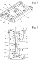
- Fig. 4 shows the cooperating with the coupling mechanism 25 plate unit 40, with the shaft door 13 at each floor 12 is coupled and also mounted vertically.
- the counter element 44 is held by a means, for example a spring, so that it can be adjusted from a rest position upwards or downwards.
- a magnetically formed counter element 44 and a locking member 50 are formed in this plate unit 40.
- This locking member 50 is displaceably mounted perpendicular to the plane of the plate and can be moved from a locked starting position in a against the coupling member 24 out notched position, whereby the plate unit 40 and with it the shaft door 13 can be brought into a fixed or in a released position ,
- This locking member 50 is shown in the locked starting position, in which opening of the shaft door 13 is prevented when the elevator is moving, as expediently a cam 51 in a groove, not shown, or the like, for example, the shaft wall 11 'and in the rail 38' almost free of play intervenes.
- the locking member 50 is guided in a longitudinal groove 53 'of a rail 53 in a base plate 42 of the disk unit 40, wherein this longitudinal groove 53' extends in the adjustment direction of the disk unit.
- an operating device 55 cooperating with the rail 53 which serves for emergency evacuation of persons in the cabin 15.
- an operating device 55 cooperating with the rail 53
- the rail 53 is held with cams in grooves 63 of the base plate 42 transverse to this liftable.
- the shaft doors can be pushed apart by hand, with the outer plates 57 pushed in one direction or the other and thereby
- the shaft door can be opened by means of a key operation and with the assistance of emergency batteries.
- the coupling element of the coupling mechanism and the counter element of the plate unit could be provided by a positive coupling as a driver of the shaft door with the car door.
- a coupling mechanism and a panel unit would be provided for each wing door of the cabin or floor, respectively. It could also be provided for each two locking members.
- the coupling mechanism according to the invention could theoretically also be fastened to the respective floor at the shaft door only, while the plate unit cooperating with the coupling mechanism could be assigned to the sliding cabin door.
- this locking member 50 could be omitted from the disk unit 40 if a lock of the hoistway door would otherwise be released.
- such a device can also be used in a railway station in mountain railways or aerial cableways for opening or closing a railway door or an outer door.
Landscapes
- Elevator Door Apparatuses (AREA)
- Power-Operated Mechanisms For Wings (AREA)
- Lock And Its Accessories (AREA)
Priority Applications (2)
| Application Number | Priority Date | Filing Date | Title |
|---|---|---|---|
| SI201531027T SI3186183T1 (sl) | 2014-08-25 | 2015-08-21 | Priprava za aktiviranje vrat kabine in jaška dvigalne naprave |
| PL15753370T PL3186183T3 (pl) | 2014-08-25 | 2015-08-21 | Urządzenie do uruchamiania drzwi kabiny i szybu instalacji dźwigowej |
Applications Claiming Priority (2)
| Application Number | Priority Date | Filing Date | Title |
|---|---|---|---|
| CH01300/14A CH710032B1 (de) | 2014-08-25 | 2014-08-25 | Einrichtung für eine Aufzugsanlage zum Betätigen wenigstens einer Kabinen- bzw. Schachttüre. |
| PCT/EP2015/069253 WO2016030296A1 (de) | 2014-08-25 | 2015-08-21 | Einrichtung zum betätigen einer kabinen- und schachttür einer aufzugsanlage |
Publications (2)
| Publication Number | Publication Date |
|---|---|
| EP3186183A1 EP3186183A1 (de) | 2017-07-05 |
| EP3186183B1 true EP3186183B1 (de) | 2019-09-11 |
Family
ID=53900829
Family Applications (1)
| Application Number | Title | Priority Date | Filing Date |
|---|---|---|---|
| EP15753370.4A Active EP3186183B1 (de) | 2014-08-25 | 2015-08-21 | Einrichtung zum betätigen einer kabinen- und schachttür einer aufzugsanlage |
Country Status (12)
| Country | Link |
|---|---|
| US (2) | US10392229B2 (es) |
| EP (1) | EP3186183B1 (es) |
| CN (1) | CN107074501B (es) |
| AR (1) | AR101681A1 (es) |
| CH (1) | CH710032B1 (es) |
| ES (1) | ES2761642T3 (es) |
| HU (1) | HUE047718T2 (es) |
| PL (1) | PL3186183T3 (es) |
| PT (1) | PT3186183T (es) |
| SI (1) | SI3186183T1 (es) |
| TW (1) | TWI673227B (es) |
| WO (1) | WO2016030296A1 (es) |
Families Citing this family (6)
| Publication number | Priority date | Publication date | Assignee | Title |
|---|---|---|---|---|
| CH710032B1 (de) | 2014-08-25 | 2018-04-13 | Salvenmoser Michael | Einrichtung für eine Aufzugsanlage zum Betätigen wenigstens einer Kabinen- bzw. Schachttüre. |
| DE102017111560A1 (de) | 2017-05-26 | 2018-11-29 | Thyssenkrupp Ag | Fahrkorb für eine Aufzugsanlage und Verfahren zum Öffnen und Schließen einer Türöffnung |
| CN109956386B (zh) * | 2017-12-14 | 2024-04-09 | 湖南捷达电梯工程有限公司 | 一种电梯门机系统 |
| CN109281587B (zh) * | 2018-10-29 | 2023-10-20 | 上海东铁五金有限公司 | 带防脱功能的平移式紧急疏散自动门 |
| JP6810916B1 (ja) * | 2020-03-03 | 2021-01-13 | フジテック株式会社 | ドア用係合装置 |
| CN112061937A (zh) * | 2020-09-24 | 2020-12-11 | 中国五冶集团有限公司 | 一种施工电梯 |
Family Cites Families (17)
| Publication number | Priority date | Publication date | Assignee | Title |
|---|---|---|---|---|
| US2481124A (en) * | 1944-09-13 | 1949-09-06 | Express Lift Co Ltd | Door-operating mechanism for lift doors and the like |
| GB712722A (en) | 1952-06-03 | 1954-07-28 | Wm Wadsworth & Sons Ltd | Improvements relating to the doors of lifts |
| US3033317A (en) | 1956-10-25 | 1962-05-08 | Montgomery Elevator | Mechanism for operating an elevator hatch door and interlock |
| US2996152A (en) | 1960-04-06 | 1961-08-15 | Olexson George | Magnetic retractable door roller for automatic elevators |
| JPS538973B2 (es) | 1972-07-25 | 1978-04-03 | ||
| JPH05162956A (ja) | 1991-12-12 | 1993-06-29 | Toshiba Corp | エレベータドア装置 |
| US5487449A (en) * | 1994-04-06 | 1996-01-30 | Otis Elevator Company | Magnetic elevator door coupling |
| US5896952A (en) * | 1996-08-22 | 1999-04-27 | Inventio Ag | Apparatus for coupling elevator doors |
| ES2212019T3 (es) * | 1996-09-17 | 2004-07-16 | Inventio Ag | Dispositivo para el arrastre de puertas en caja en ascensores. |
| CA2267428A1 (en) * | 1996-10-03 | 1998-04-09 | Inventio Ag | Operating system for lift doors |
| US6070700A (en) * | 1997-09-16 | 2000-06-06 | Inventio Ag | Operating system for elevator doors |
| WO2008118163A1 (en) | 2007-03-23 | 2008-10-02 | Otis Elevator Company | Electromagnetic coupling with a slider layer |
| EP2138442A1 (de) | 2008-06-25 | 2009-12-30 | Inventio Ag | Aufzugtürsystem mit Kabinentürverriegelung |
| US8746412B2 (en) | 2008-12-19 | 2014-06-10 | Otis Elevator Company | Elevator door frame with electronics housing |
| CN201990356U (zh) * | 2011-02-15 | 2011-09-28 | 苏州莱茵电梯制造有限公司 | 一种应用于电梯上的动力层门系统 |
| DE202014102534U1 (de) * | 2014-05-13 | 2015-08-18 | Wittur Holding Gmbh | Türkuppler mit flexibel positionierbaren Kupplerkufen |
| CH710032B1 (de) | 2014-08-25 | 2018-04-13 | Salvenmoser Michael | Einrichtung für eine Aufzugsanlage zum Betätigen wenigstens einer Kabinen- bzw. Schachttüre. |
-
2014
- 2014-08-25 CH CH01300/14A patent/CH710032B1/de unknown
-
2015
- 2015-08-21 ES ES15753370T patent/ES2761642T3/es active Active
- 2015-08-21 PL PL15753370T patent/PL3186183T3/pl unknown
- 2015-08-21 PT PT157533704T patent/PT3186183T/pt unknown
- 2015-08-21 EP EP15753370.4A patent/EP3186183B1/de active Active
- 2015-08-21 HU HUE15753370A patent/HUE047718T2/hu unknown
- 2015-08-21 WO PCT/EP2015/069253 patent/WO2016030296A1/de active Application Filing
- 2015-08-21 US US15/506,283 patent/US10392229B2/en active Active
- 2015-08-21 SI SI201531027T patent/SI3186183T1/sl unknown
- 2015-08-21 CN CN201580045698.1A patent/CN107074501B/zh active Active
- 2015-08-24 TW TW104127494A patent/TWI673227B/zh active
- 2015-08-24 AR ARP150102714A patent/AR101681A1/es active IP Right Grant
-
2019
- 2019-08-26 US US16/551,173 patent/US11192755B2/en active Active
Non-Patent Citations (1)
| Title |
|---|
| None * |
Also Published As
| Publication number | Publication date |
|---|---|
| EP3186183A1 (de) | 2017-07-05 |
| US20200010303A1 (en) | 2020-01-09 |
| AR101681A1 (es) | 2017-01-04 |
| SI3186183T1 (sl) | 2020-02-28 |
| WO2016030296A1 (de) | 2016-03-03 |
| TW201620812A (zh) | 2016-06-16 |
| HUE047718T2 (hu) | 2020-05-28 |
| PT3186183T (pt) | 2019-12-18 |
| US11192755B2 (en) | 2021-12-07 |
| TWI673227B (zh) | 2019-10-01 |
| PL3186183T3 (pl) | 2020-04-30 |
| US10392229B2 (en) | 2019-08-27 |
| CH710032B1 (de) | 2018-04-13 |
| CH710032A2 (de) | 2016-02-29 |
| CN107074501A (zh) | 2017-08-18 |
| US20170267494A1 (en) | 2017-09-21 |
| CN107074501B (zh) | 2019-12-03 |
| ES2761642T3 (es) | 2020-05-20 |
Similar Documents
| Publication | Publication Date | Title |
|---|---|---|
| EP3186183B1 (de) | Einrichtung zum betätigen einer kabinen- und schachttür einer aufzugsanlage | |
| DE2164980C2 (de) | Türantriebsvorrichtung mit Verriegelungsmechanismus für Aufzüge | |
| EP0332841B1 (de) | Türantriebsvorrichtung mit Verriegelungsmechanismus für Aufzüge | |
| EP0513509B1 (de) | Aufzug | |
| EP1713712B9 (de) | Vorrichtung zur betätigung und verriegelung von aufzugstüren | |
| EP1516847B1 (de) | Einrichtung zum Verbinden einer Kabinentür mit einer Schachttür und eine Einrichtung zur Notentriegelung einer Kabinentür | |
| EP1541518B1 (de) | Aufzugs-Türantriebsvorrichtung | |
| DE602004012327T2 (de) | Mitnehmer für aufzugskabine- und schachttüren | |
| EP1820767A1 (de) | Verfahren zur Modernisierung des Kabinentürsystems eines Aufzugs und Modernisierungsbausatz zur Durchführung des Verfahrens | |
| EP3243984A1 (de) | Türschlossvorrichtung für eine paniktür | |
| EP2709941B1 (de) | Aufzugsystem | |
| EP1794399B1 (de) | Bodenverriegelung | |
| EP0679602A1 (de) | Mitnehmereinrichtung an Aufzugstüren | |
| EP0839753A1 (de) | Vorrichtung zum Öffnen und Schliessen einer Kabinentür und einer Schachttür einer Aufzugsanlage | |
| EP0748709A1 (de) | Entriegelungsvorrichtung für eine Fensterscheibe, insbesondere für Eisenbahnwaggons, mit einem Schieber | |
| WO1998014395A1 (de) | Mitnehmersystem für aufzugstüren | |
| DE19900875C2 (de) | Verriegelungsvorrichtung für eine Türanlage | |
| EP0829446A1 (de) | Mitnehmeeinrichtung für Aufzugstüren | |
| EP0912811B1 (de) | Schiebetür | |
| DE19908191C1 (de) | Automatische Flügel- oder Türanlage | |
| EP2072449B1 (de) | Türantriebsvorrichtung für Aufzugsanlagen | |
| EP0075269B1 (de) | Torantriebsgerät mit Öffnungssicherung | |
| DE60032698T2 (de) | Vorrichtung zum Öffnen und Schliessen von Aufzugstürflügeln | |
| EP1801337B1 (de) | Vorrichtung zur Schließfolgeregelung für zweiflügelige Drehtüren | |
| WO2024068245A1 (de) | Türsystem |
Legal Events
| Date | Code | Title | Description |
|---|---|---|---|
| STAA | Information on the status of an ep patent application or granted ep patent |
Free format text: STATUS: THE INTERNATIONAL PUBLICATION HAS BEEN MADE |
|
| PUAI | Public reference made under article 153(3) epc to a published international application that has entered the european phase |
Free format text: ORIGINAL CODE: 0009012 |
|
| STAA | Information on the status of an ep patent application or granted ep patent |
Free format text: STATUS: REQUEST FOR EXAMINATION WAS MADE |
|
| 17P | Request for examination filed |
Effective date: 20170201 |
|
| AK | Designated contracting states |
Kind code of ref document: A1 Designated state(s): AL AT BE BG CH CY CZ DE DK EE ES FI FR GB GR HR HU IE IS IT LI LT LU LV MC MK MT NL NO PL PT RO RS SE SI SK SM TR |
|
| AX | Request for extension of the european patent |
Extension state: BA ME |
|
| DAV | Request for validation of the european patent (deleted) | ||
| DAX | Request for extension of the european patent (deleted) | ||
| STAA | Information on the status of an ep patent application or granted ep patent |
Free format text: STATUS: EXAMINATION IS IN PROGRESS |
|
| 17Q | First examination report despatched |
Effective date: 20181109 |
|
| GRAJ | Information related to disapproval of communication of intention to grant by the applicant or resumption of examination proceedings by the epo deleted |
Free format text: ORIGINAL CODE: EPIDOSDIGR1 |
|
| GRAP | Despatch of communication of intention to grant a patent |
Free format text: ORIGINAL CODE: EPIDOSNIGR1 |
|
| GRAP | Despatch of communication of intention to grant a patent |
Free format text: ORIGINAL CODE: EPIDOSNIGR1 |
|
| STAA | Information on the status of an ep patent application or granted ep patent |
Free format text: STATUS: GRANT OF PATENT IS INTENDED |
|
| GRAS | Grant fee paid |
Free format text: ORIGINAL CODE: EPIDOSNIGR3 |
|
| INTG | Intention to grant announced |
Effective date: 20190621 |
|
| INTG | Intention to grant announced |
Effective date: 20190628 |
|
| GRAA | (expected) grant |
Free format text: ORIGINAL CODE: 0009210 |
|
| STAA | Information on the status of an ep patent application or granted ep patent |
Free format text: STATUS: THE PATENT HAS BEEN GRANTED |
|
| AK | Designated contracting states |
Kind code of ref document: B1 Designated state(s): AL AT BE BG CH CY CZ DE DK EE ES FI FR GB GR HR HU IE IS IT LI LT LU LV MC MK MT NL NO PL PT RO RS SE SI SK SM TR |
|
| REG | Reference to a national code |
Ref country code: GB Ref legal event code: FG4D Free format text: NOT ENGLISH |
|
| REG | Reference to a national code |
Ref country code: CH Ref legal event code: EP |
|
| REG | Reference to a national code |
Ref country code: AT Ref legal event code: REF Ref document number: 1178226 Country of ref document: AT Kind code of ref document: T Effective date: 20190915 |
|
| REG | Reference to a national code |
Ref country code: DE Ref legal event code: R096 Ref document number: 502015010348 Country of ref document: DE Ref country code: IE Ref legal event code: FG4D Free format text: LANGUAGE OF EP DOCUMENT: GERMAN |
|
| REG | Reference to a national code |
Ref country code: RO Ref legal event code: EPE |
|
| REG | Reference to a national code |
Ref country code: PT Ref legal event code: SC4A Ref document number: 3186183 Country of ref document: PT Date of ref document: 20191218 Kind code of ref document: T Free format text: AVAILABILITY OF NATIONAL TRANSLATION Effective date: 20191209 |
|
| REG | Reference to a national code |
Ref country code: CH Ref legal event code: NV Representative=s name: LUCHS AND PARTNER AG PATENTANWAELTE, CH |
|
| REG | Reference to a national code |
Ref country code: SE Ref legal event code: TRGR |
|
| REG | Reference to a national code |
Ref country code: NL Ref legal event code: FP |
|
| REG | Reference to a national code |
Ref country code: LT Ref legal event code: MG4D |
|
| PG25 | Lapsed in a contracting state [announced via postgrant information from national office to epo] |
Ref country code: BG Free format text: LAPSE BECAUSE OF FAILURE TO SUBMIT A TRANSLATION OF THE DESCRIPTION OR TO PAY THE FEE WITHIN THE PRESCRIBED TIME-LIMIT Effective date: 20191211 Ref country code: NO Free format text: LAPSE BECAUSE OF FAILURE TO SUBMIT A TRANSLATION OF THE DESCRIPTION OR TO PAY THE FEE WITHIN THE PRESCRIBED TIME-LIMIT Effective date: 20191211 Ref country code: HR Free format text: LAPSE BECAUSE OF FAILURE TO SUBMIT A TRANSLATION OF THE DESCRIPTION OR TO PAY THE FEE WITHIN THE PRESCRIBED TIME-LIMIT Effective date: 20190911 Ref country code: LT Free format text: LAPSE BECAUSE OF FAILURE TO SUBMIT A TRANSLATION OF THE DESCRIPTION OR TO PAY THE FEE WITHIN THE PRESCRIBED TIME-LIMIT Effective date: 20190911 |
|
| PG25 | Lapsed in a contracting state [announced via postgrant information from national office to epo] |
Ref country code: GR Free format text: LAPSE BECAUSE OF FAILURE TO SUBMIT A TRANSLATION OF THE DESCRIPTION OR TO PAY THE FEE WITHIN THE PRESCRIBED TIME-LIMIT Effective date: 20191212 Ref country code: RS Free format text: LAPSE BECAUSE OF FAILURE TO SUBMIT A TRANSLATION OF THE DESCRIPTION OR TO PAY THE FEE WITHIN THE PRESCRIBED TIME-LIMIT Effective date: 20190911 Ref country code: AL Free format text: LAPSE BECAUSE OF FAILURE TO SUBMIT A TRANSLATION OF THE DESCRIPTION OR TO PAY THE FEE WITHIN THE PRESCRIBED TIME-LIMIT Effective date: 20190911 Ref country code: LV Free format text: LAPSE BECAUSE OF FAILURE TO SUBMIT A TRANSLATION OF THE DESCRIPTION OR TO PAY THE FEE WITHIN THE PRESCRIBED TIME-LIMIT Effective date: 20190911 |
|
| PG25 | Lapsed in a contracting state [announced via postgrant information from national office to epo] |
Ref country code: EE Free format text: LAPSE BECAUSE OF FAILURE TO SUBMIT A TRANSLATION OF THE DESCRIPTION OR TO PAY THE FEE WITHIN THE PRESCRIBED TIME-LIMIT Effective date: 20190911 |
|
| REG | Reference to a national code |
Ref country code: ES Ref legal event code: FG2A Ref document number: 2761642 Country of ref document: ES Kind code of ref document: T3 Effective date: 20200520 |
|
| REG | Reference to a national code |
Ref country code: HU Ref legal event code: AG4A Ref document number: E047718 Country of ref document: HU |
|
| PG25 | Lapsed in a contracting state [announced via postgrant information from national office to epo] |
Ref country code: CZ Free format text: LAPSE BECAUSE OF FAILURE TO SUBMIT A TRANSLATION OF THE DESCRIPTION OR TO PAY THE FEE WITHIN THE PRESCRIBED TIME-LIMIT Effective date: 20190911 Ref country code: IS Free format text: LAPSE BECAUSE OF FAILURE TO SUBMIT A TRANSLATION OF THE DESCRIPTION OR TO PAY THE FEE WITHIN THE PRESCRIBED TIME-LIMIT Effective date: 20200224 Ref country code: SM Free format text: LAPSE BECAUSE OF FAILURE TO SUBMIT A TRANSLATION OF THE DESCRIPTION OR TO PAY THE FEE WITHIN THE PRESCRIBED TIME-LIMIT Effective date: 20190911 Ref country code: SK Free format text: LAPSE BECAUSE OF FAILURE TO SUBMIT A TRANSLATION OF THE DESCRIPTION OR TO PAY THE FEE WITHIN THE PRESCRIBED TIME-LIMIT Effective date: 20190911 |
|
| REG | Reference to a national code |
Ref country code: DE Ref legal event code: R097 Ref document number: 502015010348 Country of ref document: DE |
|
| PLBE | No opposition filed within time limit |
Free format text: ORIGINAL CODE: 0009261 |
|
| STAA | Information on the status of an ep patent application or granted ep patent |
Free format text: STATUS: NO OPPOSITION FILED WITHIN TIME LIMIT |
|
| PG2D | Information on lapse in contracting state deleted |
Ref country code: IS |
|
| PG25 | Lapsed in a contracting state [announced via postgrant information from national office to epo] |
Ref country code: IS Free format text: LAPSE BECAUSE OF FAILURE TO SUBMIT A TRANSLATION OF THE DESCRIPTION OR TO PAY THE FEE WITHIN THE PRESCRIBED TIME-LIMIT Effective date: 20200112 Ref country code: DK Free format text: LAPSE BECAUSE OF FAILURE TO SUBMIT A TRANSLATION OF THE DESCRIPTION OR TO PAY THE FEE WITHIN THE PRESCRIBED TIME-LIMIT Effective date: 20190911 |
|
| 26N | No opposition filed |
Effective date: 20200615 |
|
| PG25 | Lapsed in a contracting state [announced via postgrant information from national office to epo] |
Ref country code: MC Free format text: LAPSE BECAUSE OF FAILURE TO SUBMIT A TRANSLATION OF THE DESCRIPTION OR TO PAY THE FEE WITHIN THE PRESCRIBED TIME-LIMIT Effective date: 20190911 |
|
| PG25 | Lapsed in a contracting state [announced via postgrant information from national office to epo] |
Ref country code: LU Free format text: LAPSE BECAUSE OF NON-PAYMENT OF DUE FEES Effective date: 20200821 |
|
| PG25 | Lapsed in a contracting state [announced via postgrant information from national office to epo] |
Ref country code: IE Free format text: LAPSE BECAUSE OF NON-PAYMENT OF DUE FEES Effective date: 20200821 |
|
| PG25 | Lapsed in a contracting state [announced via postgrant information from national office to epo] |
Ref country code: MT Free format text: LAPSE BECAUSE OF FAILURE TO SUBMIT A TRANSLATION OF THE DESCRIPTION OR TO PAY THE FEE WITHIN THE PRESCRIBED TIME-LIMIT Effective date: 20190911 Ref country code: CY Free format text: LAPSE BECAUSE OF FAILURE TO SUBMIT A TRANSLATION OF THE DESCRIPTION OR TO PAY THE FEE WITHIN THE PRESCRIBED TIME-LIMIT Effective date: 20190911 |
|
| PG25 | Lapsed in a contracting state [announced via postgrant information from national office to epo] |
Ref country code: MK Free format text: LAPSE BECAUSE OF FAILURE TO SUBMIT A TRANSLATION OF THE DESCRIPTION OR TO PAY THE FEE WITHIN THE PRESCRIBED TIME-LIMIT Effective date: 20190911 |
|
| PGFP | Annual fee paid to national office [announced via postgrant information from national office to epo] |
Ref country code: NL Payment date: 20230823 Year of fee payment: 9 |
|
| PGFP | Annual fee paid to national office [announced via postgrant information from national office to epo] |
Ref country code: TR Payment date: 20230814 Year of fee payment: 9 Ref country code: RO Payment date: 20230808 Year of fee payment: 9 Ref country code: IT Payment date: 20230831 Year of fee payment: 9 Ref country code: GB Payment date: 20230727 Year of fee payment: 9 Ref country code: FI Payment date: 20230823 Year of fee payment: 9 Ref country code: ES Payment date: 20230918 Year of fee payment: 9 Ref country code: CH Payment date: 20230902 Year of fee payment: 9 Ref country code: AT Payment date: 20230802 Year of fee payment: 9 |
|
| PGFP | Annual fee paid to national office [announced via postgrant information from national office to epo] |
Ref country code: SI Payment date: 20230809 Year of fee payment: 9 Ref country code: SE Payment date: 20230823 Year of fee payment: 9 Ref country code: PT Payment date: 20230817 Year of fee payment: 9 Ref country code: PL Payment date: 20230807 Year of fee payment: 9 Ref country code: HU Payment date: 20230811 Year of fee payment: 9 Ref country code: FR Payment date: 20230821 Year of fee payment: 9 Ref country code: BE Payment date: 20230822 Year of fee payment: 9 |
|
| PGFP | Annual fee paid to national office [announced via postgrant information from national office to epo] |
Ref country code: DE Payment date: 20231012 Year of fee payment: 9 |