EP3176035A1 - A rear vision system for a motor vehicle - Google Patents
A rear vision system for a motor vehicle Download PDFInfo
- Publication number
- EP3176035A1 EP3176035A1 EP15382603.7A EP15382603A EP3176035A1 EP 3176035 A1 EP3176035 A1 EP 3176035A1 EP 15382603 A EP15382603 A EP 15382603A EP 3176035 A1 EP3176035 A1 EP 3176035A1
- Authority
- EP
- European Patent Office
- Prior art keywords
- area
- vision system
- vehicle
- driving
- rear vision
- Prior art date
- Legal status (The legal status is an assumption and is not a legal conclusion. Google has not performed a legal analysis and makes no representation as to the accuracy of the status listed.)
- Ceased
Links
Images


Classifications
-
- B—PERFORMING OPERATIONS; TRANSPORTING
- B60—VEHICLES IN GENERAL
- B60R—VEHICLES, VEHICLE FITTINGS, OR VEHICLE PARTS, NOT OTHERWISE PROVIDED FOR
- B60R1/00—Optical viewing arrangements; Real-time viewing arrangements for drivers or passengers using optical image capturing systems, e.g. cameras or video systems specially adapted for use in or on vehicles
- B60R1/02—Rear-view mirror arrangements
- B60R1/04—Rear-view mirror arrangements mounted inside vehicle
-
- H—ELECTRICITY
- H04—ELECTRIC COMMUNICATION TECHNIQUE
- H04N—PICTORIAL COMMUNICATION, e.g. TELEVISION
- H04N23/00—Cameras or camera modules comprising electronic image sensors; Control thereof
- H04N23/58—Means for changing the camera field of view without moving the camera body, e.g. nutating or panning of optics or image sensors
-
- B—PERFORMING OPERATIONS; TRANSPORTING
- B60—VEHICLES IN GENERAL
- B60R—VEHICLES, VEHICLE FITTINGS, OR VEHICLE PARTS, NOT OTHERWISE PROVIDED FOR
- B60R1/00—Optical viewing arrangements; Real-time viewing arrangements for drivers or passengers using optical image capturing systems, e.g. cameras or video systems specially adapted for use in or on vehicles
- B60R1/20—Real-time viewing arrangements for drivers or passengers using optical image capturing systems, e.g. cameras or video systems specially adapted for use in or on vehicles
- B60R1/22—Real-time viewing arrangements for drivers or passengers using optical image capturing systems, e.g. cameras or video systems specially adapted for use in or on vehicles for viewing an area outside the vehicle, e.g. the exterior of the vehicle
- B60R1/23—Real-time viewing arrangements for drivers or passengers using optical image capturing systems, e.g. cameras or video systems specially adapted for use in or on vehicles for viewing an area outside the vehicle, e.g. the exterior of the vehicle with a predetermined field of view
- B60R1/26—Real-time viewing arrangements for drivers or passengers using optical image capturing systems, e.g. cameras or video systems specially adapted for use in or on vehicles for viewing an area outside the vehicle, e.g. the exterior of the vehicle with a predetermined field of view to the rear of the vehicle
-
- B—PERFORMING OPERATIONS; TRANSPORTING
- B60—VEHICLES IN GENERAL
- B60R—VEHICLES, VEHICLE FITTINGS, OR VEHICLE PARTS, NOT OTHERWISE PROVIDED FOR
- B60R1/00—Optical viewing arrangements; Real-time viewing arrangements for drivers or passengers using optical image capturing systems, e.g. cameras or video systems specially adapted for use in or on vehicles
- B60R1/20—Real-time viewing arrangements for drivers or passengers using optical image capturing systems, e.g. cameras or video systems specially adapted for use in or on vehicles
- B60R1/22—Real-time viewing arrangements for drivers or passengers using optical image capturing systems, e.g. cameras or video systems specially adapted for use in or on vehicles for viewing an area outside the vehicle, e.g. the exterior of the vehicle
- B60R1/28—Real-time viewing arrangements for drivers or passengers using optical image capturing systems, e.g. cameras or video systems specially adapted for use in or on vehicles for viewing an area outside the vehicle, e.g. the exterior of the vehicle with an adjustable field of view
-
- H—ELECTRICITY
- H04—ELECTRIC COMMUNICATION TECHNIQUE
- H04N—PICTORIAL COMMUNICATION, e.g. TELEVISION
- H04N23/00—Cameras or camera modules comprising electronic image sensors; Control thereof
- H04N23/60—Control of cameras or camera modules
- H04N23/63—Control of cameras or camera modules by using electronic viewfinders
-
- H—ELECTRICITY
- H04—ELECTRIC COMMUNICATION TECHNIQUE
- H04N—PICTORIAL COMMUNICATION, e.g. TELEVISION
- H04N7/00—Television systems
- H04N7/18—Closed-circuit television [CCTV] systems, i.e. systems in which the video signal is not broadcast
- H04N7/183—Closed-circuit television [CCTV] systems, i.e. systems in which the video signal is not broadcast for receiving images from a single remote source
-
- B—PERFORMING OPERATIONS; TRANSPORTING
- B60—VEHICLES IN GENERAL
- B60R—VEHICLES, VEHICLE FITTINGS, OR VEHICLE PARTS, NOT OTHERWISE PROVIDED FOR
- B60R2300/00—Details of viewing arrangements using cameras and displays, specially adapted for use in a vehicle
- B60R2300/30—Details of viewing arrangements using cameras and displays, specially adapted for use in a vehicle characterised by the type of image processing
- B60R2300/302—Details of viewing arrangements using cameras and displays, specially adapted for use in a vehicle characterised by the type of image processing combining image information with GPS information or vehicle data, e.g. vehicle speed, gyro, steering angle data
-
- B—PERFORMING OPERATIONS; TRANSPORTING
- B60—VEHICLES IN GENERAL
- B60R—VEHICLES, VEHICLE FITTINGS, OR VEHICLE PARTS, NOT OTHERWISE PROVIDED FOR
- B60R2300/00—Details of viewing arrangements using cameras and displays, specially adapted for use in a vehicle
- B60R2300/30—Details of viewing arrangements using cameras and displays, specially adapted for use in a vehicle characterised by the type of image processing
- B60R2300/306—Details of viewing arrangements using cameras and displays, specially adapted for use in a vehicle characterised by the type of image processing using a re-scaling of images
-
- B—PERFORMING OPERATIONS; TRANSPORTING
- B60—VEHICLES IN GENERAL
- B60R—VEHICLES, VEHICLE FITTINGS, OR VEHICLE PARTS, NOT OTHERWISE PROVIDED FOR
- B60R2300/00—Details of viewing arrangements using cameras and displays, specially adapted for use in a vehicle
- B60R2300/70—Details of viewing arrangements using cameras and displays, specially adapted for use in a vehicle characterised by an event-triggered choice to display a specific image among a selection of captured images
-
- B—PERFORMING OPERATIONS; TRANSPORTING
- B60—VEHICLES IN GENERAL
- B60R—VEHICLES, VEHICLE FITTINGS, OR VEHICLE PARTS, NOT OTHERWISE PROVIDED FOR
- B60R2300/00—Details of viewing arrangements using cameras and displays, specially adapted for use in a vehicle
- B60R2300/80—Details of viewing arrangements using cameras and displays, specially adapted for use in a vehicle characterised by the intended use of the viewing arrangement
- B60R2300/804—Details of viewing arrangements using cameras and displays, specially adapted for use in a vehicle characterised by the intended use of the viewing arrangement for lane monitoring
-
- B—PERFORMING OPERATIONS; TRANSPORTING
- B60—VEHICLES IN GENERAL
- B60R—VEHICLES, VEHICLE FITTINGS, OR VEHICLE PARTS, NOT OTHERWISE PROVIDED FOR
- B60R2300/00—Details of viewing arrangements using cameras and displays, specially adapted for use in a vehicle
- B60R2300/80—Details of viewing arrangements using cameras and displays, specially adapted for use in a vehicle characterised by the intended use of the viewing arrangement
- B60R2300/8066—Details of viewing arrangements using cameras and displays, specially adapted for use in a vehicle characterised by the intended use of the viewing arrangement for monitoring rearward traffic
Definitions
- the present invention relates to a rear vision system for a motor vehicle, specifically designed for displaying different views of the rear area of the vehicle according to user and/or vehicle driving information.
- An object of the invention is to provide a rear vision system capable of improving driving safety.
- Another object of the present invention is to provide a rear vision system capable of adapting the displayed image in function of current user and/or driving information, by means of a simple and cost-effective system.
- Another object of the present invention is to provide a rear vision system that improves driver comfort.
- Rear vision systems conventionally provide a rear view of the vehicle. Most of these systems are only used to assist drivers when parking the vehicle or exiting from a parking space. Such rear vision systems are activated when the reverse gear is engaged. Once the system is activated, an image of an area behind the vehicle is displayed.
- some systems have been adapted for monitoring the user and driving conditions, and modifying the displayed image according to said conditions.
- the application US2014240860 A1 describes an example of this kind of systems.
- the application describes a motor vehicle with an external rear-view mirror, a mirror drive coupled to the external rear-view mirror for moving the external rear-view mirror into a first mirror position or a second mirror position, and a control unit operatively configured to control the mirror drive such that the external rear-view mirror is moved between the positions in function of the driving speed determined by a vehicle speed sensor.
- the invention requires mechanical adaptations for modifying the displayed image, since the mirror is physically moved between a first and a second position. In this way, the application provides a costly and complex solution.
- the application US2011202240 A1 is an example of these systems.
- Said application describes a dynamic range display system for a vehicle capable of displaying the image captured by a camera together with a dynamic vehicle path line, which overlaps the image captured by the camera.
- the invention modifies the displayed image in function of the driving speed.
- the invention requires the driving environment monitoring by using distance sensors. Such sensors increase the cost, and complicate the data processing.
- the present invention overcomes the above mentioned drawbacks by providing a system adapted for displaying different areas of a captured image considering user and/or vehicle driving information.
- the invention refers to a rear vision system for a motor vehicle that comprises a camera for capturing an image within a field of view, and a system controller adapted for displaying a first area of the captured image, receiving and processing vehicle driving and/or user information, selecting a second area of the captured image depending on the received information, and displaying said second area.
- the first and second areas are smaller than the area of the captured image.
- the vehicle driving information comprises at least one of the following information: a change in driving direction from a forward driving direction to a reverse driving direction or vice versa, an increase or decrease in driving speed with respect to a predefined driving speed value, and a change in lane.
- the system shows different views of the area behind the vehicle by just providing a camera for capturing a rear view image, and a system controller adapted for displaying a first area of the captured image, and for selecting and displaying a second area of the captured image when at least one of the following vehicle driving information is received by the system controller: a change in driving direction, an increase or decrease in driving speed with respect to a predefined driving speed, and a lane change.
- the selection of different areas of the captured image allows displaying different views of the rearward area of the vehicle in function of current information, received from either the vehicle or a user.
- the driver is informed with a more detailed view of the area of interest.
- both the driving safety and the driver comfort are improved.
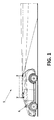
- Figure 1 shows a schematic view of a rear vision system 1 installed in a vehicle.
- the system 1 comprises a camera 2 configured to capture an image 3, and a system controller 6 configured to display a first or a second area of the captured image 3 depending the vehicle driving and/or user information.
- the camera 2 is placed at the rear part of the vehicle directed backwards to capture the area behind the vehicle.
- the camera 2 is in communication with the system controller 6 for receiving the image information associated to the image captured by the camera 2.
- the system controller 6 is adapted for displaying a first area 5 of the captured image 3, and also for receiving and processing vehicle driving and/or user information for selecting a second area 8' - 8'" of the captured image 3 depending on the received information.
- vehicle driving information at least corresponds to a change in driving direction from a forward driving direction to a reverse driving direction or vice versa, an increase or decrease in driving speed with respect to a predefined driving speed value, and a lane change.
- the system controller 6 is further adapted for selecting as second area 8' an area corresponding to a downward vertical displacement of the first area 5 such that the field of view is vertically displaced in a downward direction, when the driving direction is changed from a forward driving direction to a reverse driving direction, and selecting as second area 8' an area corresponding to an upward vertical displacement of the first area 5 such that the field of view is vertically displaced in an upward direction, when the driving direction is changed from a reverse driving direction to a forward driving direction.
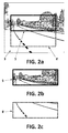
- Figures 2 and 3 show the different areas that are displayed when the controller receives a change in the driving direction.
- Figure 2a shows the entire captured image 3, and indicates the first 5 and second 8' areas, respectively displayed in Figures 2b and 2c .
- the system controller 6 is configured to change from displaying the first area 5 to display a second area 8' when the driving direction is changed from a forward driving direction to a reverse driving direction, wherein the second area 8' corresponds to a downward vertical displacement of the first area 5.
- a lower part of the captured image 3 is displayed when reverse driving is detected by the controller 6.
- the invention provides a view more centred in the ground, avoiding showing details of the upper part of the image, needless when parking, or when manoeuvring backwards.
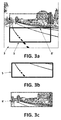
- Figure 3a shows the entire captured image 3, and indicates the first 5 and second 8' areas, respectively displayed in Figures 3b and 3c .
- the system controller 6 is configured to change from displaying the first area 5 to display a second area 8' when the driving direction is changed from a reverse driving direction to a forward driving direction, wherein the second area 8' corresponds to an upward vertical displacement of the first area 5.
- an upper part of the captured image 3 is displayed when forward driving is detected by the controller 6. This way, driver has a better view of the area of interest, which in this case, corresponds with the farthest from the vehicle.
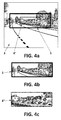
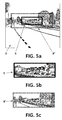
- the system controller 6 is adapted for selecting as second area 8" a part of the area of the first area 5 such that the zoom of the displayed image increases when the driving speed is increased such that it surpasses the predefined driving speed value, and selecting as second area 8" an area larger than the first area 5, where said second area 8" at least comprises the first area 5 such that the zoom of the displayed image increases when the driving speed is decreased such that it falls below the predefined driving speed value.
- Figures 4 and 5 show the different areas that are displayed when the controller receives that a speed threshold is surpassed or fallen below.
- Figure 4a shows the entire captured image 3, and indicates the first 5 and second 8" areas, respectively displayed in Figures 4b and 4c .
- the system controller 6 is configured to change from displaying the first area 5 to display a second area 8" when the driving speed is increased such that it surpasses a predefined speed threshold, wherein the second area 8" corresponds to a subarea of the first area 5.
- a smaller part of the captured image 3 is selected, and then an enlarged image is displayed when over speed is detected by the controller 6.
- the driver has a better view of the area of interest, which in this case, corresponds to a more detailed view of the farthest area from the vehicle.
- Figure 5a shows the entire captured image 3, and indicates the first 5 and second 8" areas, respectively displayed in Figures 5b and 5c .
- the system controller 6 is configured to change from displaying the first area 5 to display a second area 8" when the driving speed is decreased such that it falls below a predefined speed threshold, wherein the second area 8" comprises the first area 5.
- a larger part of the captured image 3 is selected, and then a reduced image is displayed when under speed is detected by the controller 6.
- the driver has a better view of the area of interest, which in this case, corresponds with a more general view of the rear area of the vehicle.
- the system controller 6 is adapted for selecting as second area 8'" an area corresponding to a rightward lateral displacement of the first area 5 such that the field of view is laterally displaced in a leftward direction in the event of a left lane change, and selecting as second area 8"' an area corresponding to a leftward lateral displacement of the first area 5 such that the field of view is laterally displaced in a rightward direction in the event of a right lane change.
- Figures 6 and 7 show the different areas that are displayed when the controller receives a change in lane.
- Figure 6a shows the entire captured image 3, and indicates the first 5 and second 8'" areas, respectively displayed in Figures 6b and 6c .
- the system controller 6 is configured to change from displaying the first area 5 to display a second area 8'" when a left lane change is received, and wherein said second area 8'" corresponds to a rightward horizontal displacement of the first area 5.
- a right-shift part of the captured image 3 is displayed when a leftward direction is detected by the controller 6. In this way, the driver has a better view of the area that he is invading.
- Figure 7a shows the entire captured image 3, and indicates the first 5 and second 8'" areas, respectively displayed in Figures 7b and 7c .
- the system controller 6 is configured to change from displaying the first area 5 to display a second area 8'" when a change in lane is received, and wherein said second area 8'" corresponds to a leftward horizontal displacement of the first area 5.
- a left-shift part of the captured image 3 is displayed when a rightward direction is detected by the controller 6. In this way, the driver has a better view of the area that he is invading.
- the system controller 6 is adapted for receiving an activation signal of a blinker, and for triggering a lane change event upon receiving said activation signal.
- the rear vision system 1 further comprises at least one surroundings sensor, at least one steering sensor, and a processor.
- the surroundings sensor is configured to acquire data on at least a portion of the surroundings of the vehicle to the side and/or to the rear.
- the steering sensor is configured to acquire steering angle data of the vehicle.
- the processor is adapted to process the data acquired by the at least one surroundings sensor to detect a moving object in the sensed portion of the surroundings of the vehicle, further adapted to process the steering angle data and to generate a lane change event if a moving object is detected and the steering angle is oriented towards the moving object.
- the first 5 and second areas 8', 8'" have, preferably, the same dimensions.
- the second area 8", 8"' is vertically centred with respect to the first area 5.
- the second area 8", 8'" is horizontally centred with respect to the first area 5.
- the rear vision system 1 further comprises a rear-view mirror 7, and a display 4 integrated into the rear-view mirror 3 for displaying the first 5 and second 8' - 8'" areas of the captured image 3.
- the rear view system of the invention allows assisting drivers at least when the controller detects: a change in driving direction from a forward driving direction to a reverse driving direction or vice versa, an increase or decrease in driving speed with respect to a predefined driving speed value, and a change in lane. Therefore, the invention improves driving safety and driver comfort, since only the area of interest is shown to the driver.
- Figure 8 shows an exploded view of a preferred embodiment of the rear-view mirror 7.
- the rear-view mirror 7 is an interior rear-view mirror.
- the rear-view mirror 7 comprises a display 4 integrated into the rear-view mirror 7 configured to display the first 5 and second 8' - 8'" areas of the captured image 3. Further, the rear-view mirror 7 may comprise a half mirror 13, integrated into the rear-view mirror 7 and mounted onto the display 4.
- the rear-view mirror 7 preferentially comprises a housing having a rear cover 10 and a front frame 12, a rubber pad 11, the half mirror 13, and the display 4.
- the housing encloses and protects the elements that form the rear-view mirror 7, and the rubber pad 11 helps to secure the enclosed elements.
- the half mirror 13 is adapted for showing the image displayed if it receives more light from the display 4 than from the outside, and for showing a reflected image if it receives more light from the outside than from the display 4.
- the half mirror 13, also known as one-way mirror, is an ordinary mirror that is coated on its back surface with a thin layer of metal, usually silver or aluminium, such that part of the light is reflected, and the other part penetrates the mirror 13.
- the invention allows offering two working modes, one when the display is on, and the other one when the display is off.
- the invention further comprises a vehicle comprising at least one of a dashboard, a header, a windshield or an A-pillar, a display 4 located on a surface of one of the dashboard, the header, the windshield or the A-pillar, and the rear vision system 1 as described, where the display 4 is adapted for displaying the first 5 and a second area 8' - 8"' of the captured image 3.
Landscapes
- Engineering & Computer Science (AREA)
- Multimedia (AREA)
- Mechanical Engineering (AREA)
- Signal Processing (AREA)
- Closed-Circuit Television Systems (AREA)
- Traffic Control Systems (AREA)
Priority Applications (5)
| Application Number | Priority Date | Filing Date | Title |
|---|---|---|---|
| EP15382603.7A EP3176035A1 (en) | 2015-12-03 | 2015-12-03 | A rear vision system for a motor vehicle |
| EP16201705.7A EP3176037B1 (en) | 2015-12-03 | 2016-12-01 | A rear vision system for a motor vehicle |
| JP2016236140A JP6746480B2 (ja) | 2015-12-03 | 2016-12-05 | 自動車のための後方映像システム |
| CN201611104416.3A CN107054222B (zh) | 2015-12-03 | 2016-12-05 | 一种用于机动车辆的后视系统 |
| US15/369,709 US20170163863A1 (en) | 2015-12-03 | 2016-12-05 | Rear vision system for a motor vehicle |
Applications Claiming Priority (1)
| Application Number | Priority Date | Filing Date | Title |
|---|---|---|---|
| EP15382603.7A EP3176035A1 (en) | 2015-12-03 | 2015-12-03 | A rear vision system for a motor vehicle |
Publications (1)
| Publication Number | Publication Date |
|---|---|
| EP3176035A1 true EP3176035A1 (en) | 2017-06-07 |
Family
ID=54838299
Family Applications (2)
| Application Number | Title | Priority Date | Filing Date |
|---|---|---|---|
| EP15382603.7A Ceased EP3176035A1 (en) | 2015-12-03 | 2015-12-03 | A rear vision system for a motor vehicle |
| EP16201705.7A Active EP3176037B1 (en) | 2015-12-03 | 2016-12-01 | A rear vision system for a motor vehicle |
Family Applications After (1)
| Application Number | Title | Priority Date | Filing Date |
|---|---|---|---|
| EP16201705.7A Active EP3176037B1 (en) | 2015-12-03 | 2016-12-01 | A rear vision system for a motor vehicle |
Country Status (4)
| Country | Link |
|---|---|
| US (1) | US20170163863A1 (enExample) |
| EP (2) | EP3176035A1 (enExample) |
| JP (1) | JP6746480B2 (enExample) |
| CN (1) | CN107054222B (enExample) |
Cited By (5)
| Publication number | Priority date | Publication date | Assignee | Title |
|---|---|---|---|---|
| EP3431338A1 (en) * | 2017-07-19 | 2019-01-23 | Fico Mirrors, S.A. | Vehicle image processing system |
| EP3566904A1 (en) * | 2018-05-11 | 2019-11-13 | Toyota Jidosha Kabushiki Kaisha | Image display apparatus |
| EP3674140A1 (en) * | 2018-12-26 | 2020-07-01 | Toyota Jidosha Kabushiki Kaisha | Electronic mirror system |
| US10857943B2 (en) | 2018-09-05 | 2020-12-08 | Toyota Jidosha Kabushiki Kaisha | Vehicle surroundings display device |
| FR3142406A1 (fr) * | 2022-11-29 | 2024-05-31 | Psa Automobiles Sa | Procédé de commande d’un affichage d’une image d’une caméra de recul, et véhicule associé. |
Families Citing this family (19)
| Publication number | Priority date | Publication date | Assignee | Title |
|---|---|---|---|---|
| DE102016007522B4 (de) * | 2016-06-20 | 2022-07-07 | Mekra Lang Gmbh & Co. Kg | Spiegelersatzsystem für ein Fahrzeug |
| JP6597588B2 (ja) * | 2016-12-20 | 2019-10-30 | トヨタ自動車株式会社 | 画像表示装置 |
| JP6601422B2 (ja) * | 2017-01-11 | 2019-11-06 | トヨタ自動車株式会社 | 画像表示装置 |
| JP6767690B2 (ja) * | 2017-03-31 | 2020-10-14 | パナソニックIpマネジメント株式会社 | 電子ミラー装置 |
| US11203295B2 (en) * | 2017-04-14 | 2021-12-21 | Panasonic Automotive Svstems Company of America, Division of Panasonic Corporation of North America | Rearview head up display |
| US20190098226A1 (en) * | 2017-09-26 | 2019-03-28 | Panasonic Automotive Systems Company Of America, Division Of Panasonic Corporation Of North America | Smart field of view (fov) adjustment for a rearview display system in a motor vehicle |
| WO2019135099A1 (en) * | 2018-01-05 | 2019-07-11 | Volvo Truck Corporation | Camera monitoring system with a display displaying an undistorted portion of a wide angle image adjoining at least one distorted portion of the wide angle image |
| DE102018115236A1 (de) * | 2018-06-25 | 2020-01-02 | Spc Sunflower Plastic Compound Gmbh | Mehrschichtige Folie, insbesondere Siegelfolie |
| FR3085910A1 (fr) * | 2018-09-19 | 2020-03-20 | Psa Automobiles Sa | Procede et systeme de retrovision numerique pour un vehicule automobile |
| CN112867631B (zh) | 2018-11-13 | 2024-04-12 | 瑞维安知识产权控股有限责任公司 | 用于控制车辆摄像头的系统和方法 |
| CN111756984A (zh) * | 2019-03-26 | 2020-10-09 | 深圳市赛格导航科技股份有限公司 | 一种实现倒车实时图像半全景的图像处理方法和系统 |
| JP7434730B2 (ja) | 2019-06-14 | 2024-02-21 | マツダ株式会社 | 車両用情報表示装置及び車両用制御装置 |
| KR102703277B1 (ko) * | 2019-06-19 | 2024-09-04 | 현대자동차주식회사 | 수직방향 접이식 카메라 모니터링 시스템 |
| US11180090B2 (en) | 2020-01-15 | 2021-11-23 | Toyota Motor Engineering & Manufacturing North America, Inc. | Apparatus and method for camera view selection/suggestion |
| KR102284128B1 (ko) * | 2020-03-23 | 2021-07-30 | 삼성전기주식회사 | 차량용 카메라 |
| CN113382294B (zh) * | 2021-06-04 | 2023-05-12 | 广州小鹏汽车科技有限公司 | 远程驾驶舱的画面显示处理方法、装置、驾驶舱及系统 |
| JP2024091163A (ja) * | 2022-12-23 | 2024-07-04 | 株式会社東海理化電機製作所 | 映像表示システム |
| US20240208417A1 (en) * | 2022-12-23 | 2024-06-27 | Kabushiki Kaisha Tokai-Rika-Denki-Seisakusho | Image display system and display control device |
| WO2025028945A1 (ko) * | 2023-07-31 | 2025-02-06 | 팅크웨어(주) | 디지털 리어 미러 장치와 시스템 및 그의 동작 방법 |
Citations (6)
| Publication number | Priority date | Publication date | Assignee | Title |
|---|---|---|---|---|
| WO2009132617A1 (de) * | 2008-04-29 | 2009-11-05 | Magna Electronics Europe Gmbh & Co. Kg | Vorrichtung und verfahren zum erfassen und anzeigen des rückwärtigen und/oder seitlichen umfeldes eines kraftfahrzeugs |
| DE102010020201A1 (de) * | 2009-11-06 | 2011-05-12 | Volkswagen Ag | Verfahren und Vorrichtung zur Darstellung der Bilder eines Rückblickkamerasystems eines Kraftfahrzeugs |
| US20110202240A1 (en) | 2010-02-12 | 2011-08-18 | Robert Bosch Gmbh | Dynamic range display for automotive rear-view and parking systems |
| US20120169875A1 (en) * | 2011-01-05 | 2012-07-05 | Denso Corporation | Rearward view assistance apparatus |
| WO2013093603A1 (en) * | 2011-12-22 | 2013-06-27 | Toyota Jidosha Kabushiki Kaisha | Vehicle rear monitoring system |
| US20140240860A1 (en) | 2011-11-02 | 2014-08-28 | Bayerische Motoren Werke Aktiengesellschaft | Motor Vehicle with an External Rear-View Mirror |
Family Cites Families (27)
| Publication number | Priority date | Publication date | Assignee | Title |
|---|---|---|---|---|
| US6891563B2 (en) * | 1996-05-22 | 2005-05-10 | Donnelly Corporation | Vehicular vision system |
| JPH0952555A (ja) * | 1995-08-11 | 1997-02-25 | Mitsubishi Electric Corp | 周辺監視装置 |
| JP3638169B2 (ja) * | 1996-02-16 | 2005-04-13 | 本田技研工業株式会社 | 車両衝突予防装置 |
| JPH1178693A (ja) * | 1997-09-16 | 1999-03-23 | Niles Parts Co Ltd | 車両用監視装置 |
| EP1004916A1 (en) * | 1998-11-25 | 2000-05-31 | Donnelly Corporation | Wide angle imaging system for vehicle |
| US6977630B1 (en) * | 2000-07-18 | 2005-12-20 | University Of Minnesota | Mobility assist device |
| JP2003346163A (ja) * | 2002-05-27 | 2003-12-05 | Nissan Motor Co Ltd | 車両用走行路認識装置 |
| JP2005328181A (ja) * | 2004-05-12 | 2005-11-24 | Mitsubishi Electric Corp | 周囲確認装置 |
| ES2258399B1 (es) * | 2005-02-04 | 2007-11-16 | Fico Mirrors, S.A. | Metodo y sistema para mejorar la supervision de un ambiente exterior de un vehiculo automovil. |
| JP4762698B2 (ja) * | 2005-11-30 | 2011-08-31 | アルパイン株式会社 | 車両周辺画像表示装置 |
| WO2008038370A1 (fr) * | 2006-09-28 | 2008-04-03 | Pioneer Corporation | Détecteur, procédé et programme d'informations de circulation et support d'enregistrement |
| US20090179916A1 (en) * | 2008-01-10 | 2009-07-16 | Williams Steven A | Method and apparatus for calibrating a video display overlay |
| JP4788778B2 (ja) * | 2009-01-27 | 2011-10-05 | 株式会社デンソー | 逸脱警報装置、および逸脱警報プログラム |
| JP5064601B2 (ja) * | 2009-06-29 | 2012-10-31 | パナソニック株式会社 | 車載用映像表示装置 |
| US9264672B2 (en) * | 2010-12-22 | 2016-02-16 | Magna Mirrors Of America, Inc. | Vision display system for vehicle |
| JP2012195634A (ja) * | 2011-03-15 | 2012-10-11 | Panasonic Corp | 車両後方視認装置 |
| US9357208B2 (en) * | 2011-04-25 | 2016-05-31 | Magna Electronics Inc. | Method and system for dynamically calibrating vehicular cameras |
| JP5810842B2 (ja) * | 2011-11-02 | 2015-11-11 | アイシン・エィ・ダブリュ株式会社 | レーン案内表示システム、方法およびプログラム |
| US9168924B2 (en) * | 2012-03-26 | 2015-10-27 | GM Global Technology Operations LLC | System diagnosis in autonomous driving |
| WO2013157184A1 (ja) * | 2012-04-16 | 2013-10-24 | 日産自動車株式会社 | 車両用後方視界支援装置及び車両用後方視界支援方法 |
| JP5820787B2 (ja) * | 2012-08-30 | 2015-11-24 | 株式会社デンソー | 画像処理装置、及びプログラム |
| US20140114534A1 (en) * | 2012-10-19 | 2014-04-24 | GM Global Technology Operations LLC | Dynamic rearview mirror display features |
| JP2014116756A (ja) * | 2012-12-07 | 2014-06-26 | Toyota Motor Corp | 周辺監視システム |
| EP2963922B1 (en) * | 2013-02-28 | 2019-02-27 | Aisin Seiki Kabushiki Kaisha | Program and device for controlling vehicle |
| JP6364702B2 (ja) * | 2013-03-29 | 2018-08-01 | アイシン精機株式会社 | 画像表示制御装置、画像表示システム、および表示ユニット |
| US10029621B2 (en) * | 2013-05-16 | 2018-07-24 | Ford Global Technologies, Llc | Rear view camera system using rear view mirror location |
| CN106183992B (zh) * | 2013-10-04 | 2019-03-15 | 本田技研工业株式会社 | 停车辅助装置 |
-
2015
- 2015-12-03 EP EP15382603.7A patent/EP3176035A1/en not_active Ceased
-
2016
- 2016-12-01 EP EP16201705.7A patent/EP3176037B1/en active Active
- 2016-12-05 CN CN201611104416.3A patent/CN107054222B/zh active Active
- 2016-12-05 JP JP2016236140A patent/JP6746480B2/ja active Active
- 2016-12-05 US US15/369,709 patent/US20170163863A1/en not_active Abandoned
Patent Citations (6)
| Publication number | Priority date | Publication date | Assignee | Title |
|---|---|---|---|---|
| WO2009132617A1 (de) * | 2008-04-29 | 2009-11-05 | Magna Electronics Europe Gmbh & Co. Kg | Vorrichtung und verfahren zum erfassen und anzeigen des rückwärtigen und/oder seitlichen umfeldes eines kraftfahrzeugs |
| DE102010020201A1 (de) * | 2009-11-06 | 2011-05-12 | Volkswagen Ag | Verfahren und Vorrichtung zur Darstellung der Bilder eines Rückblickkamerasystems eines Kraftfahrzeugs |
| US20110202240A1 (en) | 2010-02-12 | 2011-08-18 | Robert Bosch Gmbh | Dynamic range display for automotive rear-view and parking systems |
| US20120169875A1 (en) * | 2011-01-05 | 2012-07-05 | Denso Corporation | Rearward view assistance apparatus |
| US20140240860A1 (en) | 2011-11-02 | 2014-08-28 | Bayerische Motoren Werke Aktiengesellschaft | Motor Vehicle with an External Rear-View Mirror |
| WO2013093603A1 (en) * | 2011-12-22 | 2013-06-27 | Toyota Jidosha Kabushiki Kaisha | Vehicle rear monitoring system |
Cited By (8)
| Publication number | Priority date | Publication date | Assignee | Title |
|---|---|---|---|---|
| EP3431338A1 (en) * | 2017-07-19 | 2019-01-23 | Fico Mirrors, S.A. | Vehicle image processing system |
| CN109286783A (zh) * | 2017-07-19 | 2019-01-29 | 法可镜子股份公司 | 车辆图像处理系统 |
| CN109286783B (zh) * | 2017-07-19 | 2021-07-09 | 法可镜子股份公司 | 车辆图像处理系统 |
| EP3566904A1 (en) * | 2018-05-11 | 2019-11-13 | Toyota Jidosha Kabushiki Kaisha | Image display apparatus |
| US11244173B2 (en) | 2018-05-11 | 2022-02-08 | Toyota Jidosha Kabushiki Kaisha | Image display apparatus |
| US10857943B2 (en) | 2018-09-05 | 2020-12-08 | Toyota Jidosha Kabushiki Kaisha | Vehicle surroundings display device |
| EP3674140A1 (en) * | 2018-12-26 | 2020-07-01 | Toyota Jidosha Kabushiki Kaisha | Electronic mirror system |
| FR3142406A1 (fr) * | 2022-11-29 | 2024-05-31 | Psa Automobiles Sa | Procédé de commande d’un affichage d’une image d’une caméra de recul, et véhicule associé. |
Also Published As
| Publication number | Publication date |
|---|---|
| CN107054222B (zh) | 2022-04-22 |
| EP3176037B1 (en) | 2018-09-12 |
| US20170163863A1 (en) | 2017-06-08 |
| JP6746480B2 (ja) | 2020-08-26 |
| JP2017100718A (ja) | 2017-06-08 |
| CN107054222A (zh) | 2017-08-18 |
| EP3176037A1 (en) | 2017-06-07 |
Similar Documents
| Publication | Publication Date | Title |
|---|---|---|
| EP3176035A1 (en) | A rear vision system for a motor vehicle | |
| JP7831772B2 (ja) | カメラ監視システムにおけるトレーラ端部のトラッキング | |
| US20230012629A1 (en) | Electronic device for displaying image by using camera monitoring system (cms) side display mounted in vehicle, and operation method thereof | |
| JP6877311B2 (ja) | 車両運転支援システム | |
| US9221384B2 (en) | Method for controlling a display device of a motor vehicle | |
| EP2607941B1 (en) | Vehicle windshield display with obstruction detection | |
| US7379089B2 (en) | Apparatus and method for monitoring the immediate surroundings of a vehicle | |
| US20100201508A1 (en) | Cross traffic alert system for a vehicle, and related alert display method | |
| JP5310602B2 (ja) | 車両用周辺監視システム | |
| EP2974909A1 (en) | Periphery surveillance apparatus and program | |
| US20130096820A1 (en) | Virtual display system for a vehicle | |
| JP2003511288A (ja) | 駐車する車両の周辺状況を監視するための装置 | |
| EP2884735A1 (en) | Method for operating a rear view camera system of a motor vehicle, rear view camera system and motor vehicle | |
| US20220144169A1 (en) | Rear-view camera system for a trailer hitch system | |
| KR20190018708A (ko) | 디지털 백미러 제어 유닛 및 방법 | |
| KR102460043B1 (ko) | 차량의 적응형 순항 제어를 위한 추월 가속 지원 | |
| CN105323539B (zh) | 车用安全系统及其操作方法 | |
| JP6439233B2 (ja) | 車両用画像表示装置及び画像処理方法 | |
| US9783055B2 (en) | Driver assistance system | |
| KR101714077B1 (ko) | 차량용 후방감지 카메라의 시야각 조절 시스템 | |
| JP7388329B2 (ja) | 車両表示システム及び車両表示方法 | |
| JP5289920B2 (ja) | 車両用警報装置 | |
| JP2018069806A (ja) | 表示制御装置 | |
| EP2797050A1 (en) | A safety system and method for a motor vehicle | |
| JP5042201B2 (ja) | 車両用警報装置 |
Legal Events
| Date | Code | Title | Description |
|---|---|---|---|
| AK | Designated contracting states |
Kind code of ref document: A1 Designated state(s): AL AT BE BG CH CY CZ DE DK EE ES FI FR GB GR HR HU IE IS IT LI LT LU LV MC MK MT NL NO PL PT RO RS SE SI SK SM TR |
|
| AX | Request for extension of the european patent |
Extension state: BA ME |
|
| PUAI | Public reference made under article 153(3) epc to a published international application that has entered the european phase |
Free format text: ORIGINAL CODE: 0009012 |
|
| STAA | Information on the status of an ep patent application or granted ep patent |
Free format text: STATUS: THE APPLICATION HAS BEEN PUBLISHED |
|
| STAA | Information on the status of an ep patent application or granted ep patent |
Free format text: STATUS: REQUEST FOR EXAMINATION WAS MADE |
|
| 17P | Request for examination filed |
Effective date: 20171204 |
|
| RBV | Designated contracting states (corrected) |
Designated state(s): AL AT BE BG CH CY CZ DE DK EE ES FI FR GB GR HR HU IE IS IT LI LT LU LV MC MK MT NL NO PL PT RO RS SE SI SK SM TR |
|
| STAA | Information on the status of an ep patent application or granted ep patent |
Free format text: STATUS: EXAMINATION IS IN PROGRESS |
|
| 17Q | First examination report despatched |
Effective date: 20180924 |
|
| STAA | Information on the status of an ep patent application or granted ep patent |
Free format text: STATUS: THE APPLICATION HAS BEEN REFUSED |
|
| 18R | Application refused |
Effective date: 20210124 |