EP3173509A1 - Systèmes et procédés électrochimiques utilisant une oxydation de métal - Google Patents
Systèmes et procédés électrochimiques utilisant une oxydation de métal Download PDFInfo
- Publication number
- EP3173509A1 EP3173509A1 EP16188593.4A EP16188593A EP3173509A1 EP 3173509 A1 EP3173509 A1 EP 3173509A1 EP 16188593 A EP16188593 A EP 16188593A EP 3173509 A1 EP3173509 A1 EP 3173509A1
- Authority
- EP
- European Patent Office
- Prior art keywords
- cathode
- anode
- oxidation state
- metal ion
- electrolyte
- Prior art date
- Legal status (The legal status is an assumption and is not a legal conclusion. Google has not performed a legal analysis and makes no representation as to the accuracy of the status listed.)
- Withdrawn
Links
Images


Classifications
-
- C—CHEMISTRY; METALLURGY
- C25—ELECTROLYTIC OR ELECTROPHORETIC PROCESSES; APPARATUS THEREFOR
- C25B—ELECTROLYTIC OR ELECTROPHORETIC PROCESSES FOR THE PRODUCTION OF COMPOUNDS OR NON-METALS; APPARATUS THEREFOR
- C25B3/00—Electrolytic production of organic compounds
- C25B3/20—Processes
- C25B3/27—Halogenation
-
- B—PERFORMING OPERATIONS; TRANSPORTING
- B01—PHYSICAL OR CHEMICAL PROCESSES OR APPARATUS IN GENERAL
- B01J—CHEMICAL OR PHYSICAL PROCESSES, e.g. CATALYSIS OR COLLOID CHEMISTRY; THEIR RELEVANT APPARATUS
- B01J27/00—Catalysts comprising the elements or compounds of halogens, sulfur, selenium, tellurium, phosphorus or nitrogen; Catalysts comprising carbon compounds
- B01J27/06—Halogens; Compounds thereof
- B01J27/08—Halides
- B01J27/122—Halides of copper
-
- B—PERFORMING OPERATIONS; TRANSPORTING
- B01—PHYSICAL OR CHEMICAL PROCESSES OR APPARATUS IN GENERAL
- B01J—CHEMICAL OR PHYSICAL PROCESSES, e.g. CATALYSIS OR COLLOID CHEMISTRY; THEIR RELEVANT APPARATUS
- B01J27/00—Catalysts comprising the elements or compounds of halogens, sulfur, selenium, tellurium, phosphorus or nitrogen; Catalysts comprising carbon compounds
- B01J27/06—Halogens; Compounds thereof
- B01J27/132—Halogens; Compounds thereof with chromium, molybdenum, tungsten or polonium
-
- C—CHEMISTRY; METALLURGY
- C07—ORGANIC CHEMISTRY
- C07C—ACYCLIC OR CARBOCYCLIC COMPOUNDS
- C07C17/00—Preparation of halogenated hydrocarbons
- C07C17/013—Preparation of halogenated hydrocarbons by addition of halogens
- C07C17/02—Preparation of halogenated hydrocarbons by addition of halogens to unsaturated hydrocarbons
-
- C—CHEMISTRY; METALLURGY
- C07—ORGANIC CHEMISTRY
- C07D—HETEROCYCLIC COMPOUNDS
- C07D301/00—Preparation of oxiranes
- C07D301/02—Synthesis of the oxirane ring
- C07D301/03—Synthesis of the oxirane ring by oxidation of unsaturated compounds, or of mixtures of unsaturated and saturated compounds
-
- C—CHEMISTRY; METALLURGY
- C08—ORGANIC MACROMOLECULAR COMPOUNDS; THEIR PREPARATION OR CHEMICAL WORKING-UP; COMPOSITIONS BASED THEREON
- C08F—MACROMOLECULAR COMPOUNDS OBTAINED BY REACTIONS ONLY INVOLVING CARBON-TO-CARBON UNSATURATED BONDS
- C08F14/00—Homopolymers and copolymers of compounds having one or more unsaturated aliphatic radicals, each having only one carbon-to-carbon double bond, and at least one being terminated by a halogen
-
- C—CHEMISTRY; METALLURGY
- C25—ELECTROLYTIC OR ELECTROPHORETIC PROCESSES; APPARATUS THEREFOR
- C25B—ELECTROLYTIC OR ELECTROPHORETIC PROCESSES FOR THE PRODUCTION OF COMPOUNDS OR NON-METALS; APPARATUS THEREFOR
- C25B1/00—Electrolytic production of inorganic compounds or non-metals
-
- C—CHEMISTRY; METALLURGY
- C25—ELECTROLYTIC OR ELECTROPHORETIC PROCESSES; APPARATUS THEREFOR
- C25B—ELECTROLYTIC OR ELECTROPHORETIC PROCESSES FOR THE PRODUCTION OF COMPOUNDS OR NON-METALS; APPARATUS THEREFOR
- C25B1/00—Electrolytic production of inorganic compounds or non-metals
- C25B1/01—Products
- C25B1/02—Hydrogen or oxygen
-
- C—CHEMISTRY; METALLURGY
- C25—ELECTROLYTIC OR ELECTROPHORETIC PROCESSES; APPARATUS THEREFOR
- C25B—ELECTROLYTIC OR ELECTROPHORETIC PROCESSES FOR THE PRODUCTION OF COMPOUNDS OR NON-METALS; APPARATUS THEREFOR
- C25B1/00—Electrolytic production of inorganic compounds or non-metals
- C25B1/01—Products
- C25B1/14—Alkali metal compounds
- C25B1/16—Hydroxides
-
- C—CHEMISTRY; METALLURGY
- C25—ELECTROLYTIC OR ELECTROPHORETIC PROCESSES; APPARATUS THEREFOR
- C25B—ELECTROLYTIC OR ELECTROPHORETIC PROCESSES FOR THE PRODUCTION OF COMPOUNDS OR NON-METALS; APPARATUS THEREFOR
- C25B1/00—Electrolytic production of inorganic compounds or non-metals
- C25B1/01—Products
- C25B1/18—Alkaline earth metal compounds or magnesium compounds
- C25B1/20—Hydroxides
-
- C—CHEMISTRY; METALLURGY
- C25—ELECTROLYTIC OR ELECTROPHORETIC PROCESSES; APPARATUS THEREFOR
- C25B—ELECTROLYTIC OR ELECTROPHORETIC PROCESSES FOR THE PRODUCTION OF COMPOUNDS OR NON-METALS; APPARATUS THEREFOR
- C25B1/00—Electrolytic production of inorganic compounds or non-metals
- C25B1/01—Products
- C25B1/24—Halogens or compounds thereof
- C25B1/26—Chlorine; Compounds thereof
-
- C—CHEMISTRY; METALLURGY
- C25—ELECTROLYTIC OR ELECTROPHORETIC PROCESSES; APPARATUS THEREFOR
- C25B—ELECTROLYTIC OR ELECTROPHORETIC PROCESSES FOR THE PRODUCTION OF COMPOUNDS OR NON-METALS; APPARATUS THEREFOR
- C25B1/00—Electrolytic production of inorganic compounds or non-metals
- C25B1/01—Products
- C25B1/34—Simultaneous production of alkali metal hydroxides and chlorine, oxyacids or salts of chlorine, e.g. by chlor-alkali electrolysis
- C25B1/46—Simultaneous production of alkali metal hydroxides and chlorine, oxyacids or salts of chlorine, e.g. by chlor-alkali electrolysis in diaphragm cells
-
- C—CHEMISTRY; METALLURGY
- C25—ELECTROLYTIC OR ELECTROPHORETIC PROCESSES; APPARATUS THEREFOR
- C25B—ELECTROLYTIC OR ELECTROPHORETIC PROCESSES FOR THE PRODUCTION OF COMPOUNDS OR NON-METALS; APPARATUS THEREFOR
- C25B11/00—Electrodes; Manufacture thereof not otherwise provided for
- C25B11/04—Electrodes; Manufacture thereof not otherwise provided for characterised by the material
- C25B11/051—Electrodes formed of electrocatalysts on a substrate or carrier
- C25B11/073—Electrodes formed of electrocatalysts on a substrate or carrier characterised by the electrocatalyst material
- C25B11/091—Electrodes formed of electrocatalysts on a substrate or carrier characterised by the electrocatalyst material consisting of at least one catalytic element and at least one catalytic compound; consisting of two or more catalytic elements or catalytic compounds
- C25B11/095—Electrodes formed of electrocatalysts on a substrate or carrier characterised by the electrocatalyst material consisting of at least one catalytic element and at least one catalytic compound; consisting of two or more catalytic elements or catalytic compounds at least one of the compounds being organic
-
- C—CHEMISTRY; METALLURGY
- C25—ELECTROLYTIC OR ELECTROPHORETIC PROCESSES; APPARATUS THEREFOR
- C25B—ELECTROLYTIC OR ELECTROPHORETIC PROCESSES FOR THE PRODUCTION OF COMPOUNDS OR NON-METALS; APPARATUS THEREFOR
- C25B15/00—Operating or servicing cells
- C25B15/08—Supplying or removing reactants or electrolytes; Regeneration of electrolytes
-
- C—CHEMISTRY; METALLURGY
- C25—ELECTROLYTIC OR ELECTROPHORETIC PROCESSES; APPARATUS THEREFOR
- C25B—ELECTROLYTIC OR ELECTROPHORETIC PROCESSES FOR THE PRODUCTION OF COMPOUNDS OR NON-METALS; APPARATUS THEREFOR
- C25B3/00—Electrolytic production of organic compounds
- C25B3/20—Processes
- C25B3/23—Oxidation
-
- C—CHEMISTRY; METALLURGY
- C25—ELECTROLYTIC OR ELECTROPHORETIC PROCESSES; APPARATUS THEREFOR
- C25B—ELECTROLYTIC OR ELECTROPHORETIC PROCESSES FOR THE PRODUCTION OF COMPOUNDS OR NON-METALS; APPARATUS THEREFOR
- C25B9/00—Cells or assemblies of cells; Constructional parts of cells; Assemblies of constructional parts, e.g. electrode-diaphragm assemblies; Process-related cell features
- C25B9/17—Cells comprising dimensionally-stable non-movable electrodes; Assemblies of constructional parts thereof
- C25B9/19—Cells comprising dimensionally-stable non-movable electrodes; Assemblies of constructional parts thereof with diaphragms
-
- Y—GENERAL TAGGING OF NEW TECHNOLOGICAL DEVELOPMENTS; GENERAL TAGGING OF CROSS-SECTIONAL TECHNOLOGIES SPANNING OVER SEVERAL SECTIONS OF THE IPC; TECHNICAL SUBJECTS COVERED BY FORMER USPC CROSS-REFERENCE ART COLLECTIONS [XRACs] AND DIGESTS
- Y02—TECHNOLOGIES OR APPLICATIONS FOR MITIGATION OR ADAPTATION AGAINST CLIMATE CHANGE
- Y02E—REDUCTION OF GREENHOUSE GAS [GHG] EMISSIONS, RELATED TO ENERGY GENERATION, TRANSMISSION OR DISTRIBUTION
- Y02E60/00—Enabling technologies; Technologies with a potential or indirect contribution to GHG emissions mitigation
- Y02E60/30—Hydrogen technology
- Y02E60/36—Hydrogen production from non-carbon containing sources, e.g. by water electrolysis
Definitions
- the system further comprises a ligand in the anode electrolyte wherein the ligand is configured to interact with the metal ion.
- the cathode is a gas-diffusion cathode configured to react oxygen gas and water to form hydroxide ions.
- the cathode is a hydrogen gas producing cathode configured to form hydrogen gas and hydroxide ions by reducing water.
- the cathode is a hydrogen gas producing cathode configured to reduce an acid, such as, hydrochloric acid to hydrogen gas.
- the cathode is a gas-diffusion cathode configured to react hydrochloric acid and oxygen to form water.
- a method comprising contacting an anode with an anode electrolyte and oxidizing a metal ion from the lower oxidation state to a higher oxidation state at the anode; contacting a cathode with a cathode electrolyte; and preventing migration of the metal ions from the anode electrolyte to the cathode electrolyte by using a size exclusion membrane or an anion exchange membrane.
- a method comprising contacting an anode with an anode electrolyte and oxidizing a metal ion from lower oxidation state to a higher oxidation state at the anode; and contacting a cathode with a cathode electrolyte and producing hydroxide ions and/or hydrogen gas at the cathode; and producing an acid by reacting the metal ion in the higher oxidation state with hydrogen gas.
- the metal halide with metal ion in higher oxidation state optionally comprising the metal halide with the metal ion in the lower oxidation state is contacted with an unsaturated hydrocarbon and/or saturated hydrocarbon to form halohydrocarbon and the metal halide with the metal ion in the lower oxidation state.
- the metal halide with the metal ion in the lower oxidation state is re-circulated back to the anode chamber.
- a system comprising an anode chamber comprising an anode in contact with a metal ion in an anode electrolyte, wherein the anode chamber is configured to convert the metal ion from a lower oxidation state to a higher oxidation state; and a cathode chamber comprising an oxygen depolarizing cathode in contact with a cathode electrolyte, wherein the cathode chamber is configured to produce an alkali.
- a system comprising an anode in contact with an anode electrolyte wherein the anode is configured to oxidize a metal ion from the lower oxidation state to a higher oxidation state; a cathode in contact with a cathode electrolyte; and a reactor operably connected to the anode chamber and configured to react the metal ion in the higher oxidation state with an unsaturated hydrocarbon to form a green halogenated hydrocarbon.
- the metal bromide or metal iodide with the higher oxidation state produced by the anode chamber can be used for other purposes, such as, but not limited to, generation of hydrogen bromide or hydrogen iodide and/or generation of bromo or iodohydrocarbons, such as, but not limited to, monobromohydrocarbons, dibromohydrocarbons, tribromohydrocarbons, monoiodohydrocarbons, diiodohydrocarbons, triiodohydrocarbons, etc.
- the metal ion in the higher oxidation state may be sold as is in the commercial market.
- the electrochemical cell of the invention may be any electrochemical cell where the metal ion in the lower oxidation state is converted to the metal ion in the higher oxidation state in the anode chamber.
- cathode reaction may be any reaction that does or does not form an alkali in the cathode chamber.
- Such cathode consumes electrons and carries out any reaction including, but not limited to, the reaction of water to form hydroxide ions and hydrogen gas or reaction of oxygen gas and water to form hydroxide ions or reduction of protons from an acid such as hydrochloric acid to form hydrogen gas or reaction of protons from hydrochloric acid and oxygen gas to form water.
- the metal ion in the lower oxidation state and the metal ion in the higher oxidation state are both present in the anode electrolyte. In some embodiments, it may be desirable to have the metal ion in both the lower oxidation state and the higher oxidation state in the anode electrolyte. Suitable ratios of the metal ion in the lower and higher oxidation state in the anode electrolyte have been described herein.
- the mixed metal ion in the lower oxidation state with the metal ion in the higher oxidation state may assist in lower voltages in the electrochemical systems and high yield and selectivity in corresponding catalytic reactions with hydrogen gas or hydrocarbons.
- the metal ion in the anode electrolyte is a mixed metal ion.
- the anode electrolyte containing the copper ion in the lower oxidation state and the copper ion in the higher oxidation state may also contain another metal ion such as, but not limited to, iron.
- the presence of a second metal ion in the anode electrolyte may be beneficial in lowering the total energy of the electrochemical reaction in combination with the catalytic reaction.
- the metal in such methods is metal chloride such as copper chloride.
- such methods result in net energy saving of more than 100kJ/mol or more than 150kJ/mol or more than 200kJ/mol or between 100-250kJ/mol or the method results in the voltage savings of more than 1V (described below and in Fig. 8C ) .
- the unsaturated hydrocarbon in such methods is C 2 -C 5 alkene such as but not limited to, ethylene, propylene, isobutylene, 2-butene (cis and/or trans), pentene etc.
- systems that include an anode in contact with an anode electrolyte wherein the anode is configured to oxidize a metal ion from the lower oxidation state to a higher oxidation state; a ligand in the anode electrolyte wherein the ligand is configured to interact with the metal ion; and a cathode in contact with a cathode electrolyte wherein the cathode is configured to form hydroxide ions, water, and/or hydrogen gas; and a reactor configured to react the anode electrolyte containing the ligand and the metal ion in the higher oxidation state with an unsaturated hydrocarbon, hydrogen gas, saturated hydrocarbon, or combination thereof.
- the concentration of the ligand may be chosen based on various parameters, including but not limited to, concentration of the metal ion, solubility of the ligand etc.
- concentration of the metal ion concentration of the metal ion
- solubility of the ligand etc.
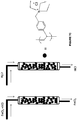
- the ligand is a substituted or unsubstituted phosphine of formula D, or an oxide thereof: wherein R 1 , R 2 , and R 3 independently are H, alkyl, substituted alkyl, alkoxy, substituted alkoxy, aryl, substituted aryl, heteroaryl, substituted heteroaryl, amine, substituted amine, cycloalkyl, substituted cycloalkyl, heterocycloalkyl, and substituted heterocycloalkyl.
- R 1 , R 2 , and R 3 independently are cycloalkyl and substituted cycloalkyl. In some embodiments of the compound of formula D or an oxide thereof, R 1 , R 2 , and R 3 independently are cycloalkyl and substituted cycloalkyl wherein the substituted cycloalkyl is substituted with a group selected from alkyl, substituted alkyl, alkoxy, substituted alkoxy, amine, and substituted amine.
- the ligand is a substituted or unsubstituted pyridine of formula E: wherein R 1 and R 2 independently are H, alkyl, substituted alkyl, heteroaryl, substituted heteroaryl, amine, and substituted amine.
- composition comprising an aqueous medium comprising a ligand selected from substituted or unsubstituted phosphine, substituted or unsubstituted crown ether, substituted or unsubstituted aliphatic nitrogen, substituted or unsubstituted pyridine, substituted or unsubstituted dinitrile, and combination thereof, a metal ion; a salt; and an unsaturated or saturated hydrocarbon.
- a ligand selected from substituted or unsubstituted phosphine, substituted or unsubstituted crown ether, substituted or unsubstituted aliphatic nitrogen, substituted or unsubstituted pyridine, substituted or unsubstituted dinitrile, and combination thereof, a metal ion; a salt; and an unsaturated or saturated hydrocarbon.
- a method of using a ligand comprising adding a ligand to an anode electrolyte comprising a metal ion solution and resulting in one or more of properties including, but not limited to, enhanced reactivity of the metal ion towards the unsaturated hydrocarbon, saturated hydrocarbon, or hydrogen gas, enhanced selectivity of the metal ion towards halogenations of the unsaturated or saturated hydrocarbon, enhanced transfer of the halogen from the metal ion to the unsaturated hydrocarbon, saturated hydrocarbon, or the hydrogen gas, reduced redox potential of the electrochemical cell, enhanced solubility of the metal ion in the aqueous medium, reduced membrane cross-over of the metal ion to the cathode electrolyte in the electrochemical cell, reduced corrosion of the electrochemical cell and/or the reactor, enhanced separation of the metal ion from the acid solution after reaction with hydrogen gas, enhanced separation of the metal ion from the halogenated hydrocarbon solution, and combination thereof.
- a method comprising improving an efficiency of an electrochemical cell wherein the electrochemical cell comprises an anode in contact with an anode electrolyte comprising a metal ion where the anode oxidizes the metal ion from a lower oxidation state to a higher oxidation state.
- the efficiency relates to the voltage applied to the electrochemical cell.
- This term includes, by way of example, linear and branched hydrocarbyl groups such as methyl (CH 3 -), ethyl (CH 3 CH 2 -), n -propyl (CH 3 CH 2 CH 2 -), isopropyl ((CH 3 ) 2 CH-), n -butyl (CH 3 CH 2 CH 2 CH 2 -), isobutyl ((CH 3 ) 2 CHCH 2 -), sec -butyl ((CH 3 )(CH 3 CH 2 )CH-), t -butyl ((CH 3 ) 3 C-), n -pentyl (CH 3 CH 2 CH 2 CH 2 CH 2 -), and neopentyl ((CH 3 ) 3 CCH 2 -).
- linear and branched hydrocarbyl groups such as methyl (CH 3 -), ethyl (CH 3 CH 2 -), n -propyl (CH 3 CH 2 CH 2 -), isopropyl ((CH 3
- heterocycloalkyl refers to a saturated or partially saturated cyclic group having from 1 to 5 heteroatoms selected from the group consisting of nitrogen, sulfur, or oxygen and includes single ring and multiple ring systems including fused, bridged, and spiro ring systems.
- the heterocyclyl includes, but is not limited to, tetrahydropyranyl, piperidinyl, N-methylpiperidin-3-yl, piperazinyl, N-methylpyrrolidin-3-yl, 3-pyrrolidinyl, 2-pyrrolidon-1-yl, morpholinyl, and pyrrolidinyl.
- substituted alkyl refers to an alkyl group having from 1 to 5 and, in some embodiments, 1 to 3 or 1 to 2 substituents selected from the group consisting of alkenyl, halogen, -OH, -COOH, amino, substituted amino, wherein said substituents are as defined herein.
- substituted heterocycloalkyl refers to heterocyclic groups, as defined herein, that are substituted with from 1 to 5 or in some embodiments 1 to 3 of the substituents as defined for substituted cycloalkyl.
- the ratio of the concentration of the ligand and the concentration of the Cu(I) ion is between 1:1 to 4:1; or between 1:1 to 3:1; or between 1:1 to 2:1; or is 1:1; or 2:1, or 3:1, or 4:1.
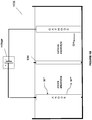
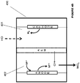
- the electrochemical system 100A includes an anode chamber with an anode in contact with an anode electrolyte where the anode electrolyte contains metal ions in lower oxidation state (represented as M L+ ) which are converted by the anode to metal ions in higher oxidation state (represented as M H+ ).
- the metal ion may be in the form of a sulfate, chloride, bromide, or iodide.
- the electron(s) generated at the anode are used to drive the reaction at the cathode.
- the cathode reaction may be any reaction known in the art.
- the anode chamber and the cathode chamber may be separated by an ion exchange membrane (IEM) that may allow the passage of ions, such as, but not limited to, sodium ions in some embodiments to the cathode electrolyte if the anode electrolyte is sodium chloride or sodium sulfate etc. containing metal halide.
- IEM ion exchange membrane
- Some reactions that may occur at the cathode include, but not limited to, reaction of water to form hydroxide ions and hydrogen gas, reaction of oxygen gas and water to form hydroxide ions, reduction of HCl to form hydrogen gas; or reaction of HCl and oxygen gas to form water.
- the size exclusion membrane as defined herein above and herein fully prevents the migration of the metal ion to the cathode chamber or the middle chamber with the third electrolyte or reduces the migration by 100%; or by 99%; or by 95% or by 75%; or by 50%; or by 25%; or between 25-50%; or between 50-75%; or between 50-95%.
- methods that include contacting an anode with a metal ion in an anode electrolyte in an anode chamber; converting the metal ion from a lower oxidation state to a higher oxidation state at the anode; contacting a cathode with a cathode electrolyte; forming water or hydrogen gas at the cathode; and treating the metal ion in the higher oxidation state in the anode electrolyte with hydrogen gas.
- the treatment of the hydrogen gas with the metal ion in the higher oxidation state may be inside the cathode chamber or outside the cathode chamber.
- the above recited methods include forming hydrogen chloride, hydrochloric acid, hydrogen bromide, hydrobromic acid, hydrogen iodide, hydroiodic acid and/or sulfuric acid by treating the metal ion in the higher oxidation state with the hydrogen gas.
- the treatment of the metal ion in the higher oxidation state with the hydrogen gas results in forming hydrogen chloride, hydrochloric acid, hydrogen bromide, hydrobromic acid, hydrogen iodide, hydroiodic acid, and/or sulfuric acid and the metal ion in the lower oxidation state.
- the metal ion in the lower oxidation state is re-circulated back to the anode chamber.
- the method does not produce chlorine gas at the anode.
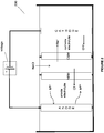
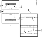
- FIG. 6 An example of the electrochemical system of Fig. 5A is as illustrated in Fig. 6 . It is to be understood that the system 600 of Fig. 6 is for illustration purposes only and other metal ions with different oxidations states (e.g., chromium, tin etc.) and other electrochemical systems forming products other than alkali such as, water (as in Fig. 5B ) or hydrogen gas (as in Fig. 4A or 4B ), in the cathode chamber, are equally applicable to the system.
- the electrochemical system 600 includes an oxygen depolarized cathode that produces hydroxide ions from water and oxygen.
- the HCl produced by this method can be used for the dissolution of minerals to generate divalent cations that can be used in carbonate precipitation processes, as described herein.
- the metal halide or metal sulfate in Fig. 6 may be reacted with the unsaturated or saturated hydrocarbon to form halohydrocarbon or sulfohydrocarbon, as described herein (not shown in the figures).
- the cathode is not a gas-diffusion cathode but is a cathode as described in Fig. 4A or 4B .
- the system 600 may be applied to any electrochemical system that produces alkali.
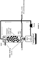
- the anolyte containing metal ions in higher oxidation state may react with the hydrogen gas to form HCl and metal ions in lower oxidation state, i.e., reduced form illustrated as FeCl 2 .
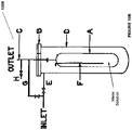
- the reaction tower may optionally contain activated charcoal or carbon or alternatively, the activated carbon may be present outside the reaction tower.
- the reaction of the metal ion with hydrogen gas may take place on the activated carbon from which the reduced anolyte may be regenerated or the activated carbon may simply act as a filter for removing impurities from the gases.
- the reaction of metal ion in the higher oxidation state (formed as shown in the figures) with hydrogen gas is also illustrated in Fig. 7B .
- the anolyte from the anode chamber containing the metal ions in the higher oxidation state such as, but not limited to, Fe 3+ , Sn 4+ , Cr 3+ , etc. may be used to react with hydrogen gas to form HCl or may be used to scrub the SO 2 containing gas to form clean gas or sulfuric acid.
- NOx gases may be reacted with the metal ions in the higher oxidation state to form nitric acid.
- the reaction of the metal ion with hydrogen gas or SO 2 gas may take place on the activated carbon from which the reduced anolyte may be regenerated or the activated carbon may simply act as a filter for removing impurities from the gases.
- the reduced anolyte containing HCl and/or H 2 SO 4 and the metal ions in lower oxidation state may be subjected to acid recovery using separation techniques known in the art including, but not limited to, ion exchange resin, size exclusion membranes, and acid dialysis, etc. to separate HCl and/or H 2 SO 4 from the anolyte.
- the ligands, described herein may facilitate the separation of the metal ion from the acid solution due to the large size of the ligand attached to the metal ion.
- the anolyte containing the metal ion in the lower oxidation state may be re-circulated back to the electrochemical cell and HCl and/or H 2 SO 4 may be collected.
- the reaction inside the reaction tower may take place from 1-10hr at a temperature of 50-100°C.
- an ion exchange resin to separate out the HCl from the metal containing anolyte is as illustrated in Fig. 7C .
- the separation process may include a preferential adsorption/absorption of a mineral acid to an anion exchange resin.
- the anolyte containing HCl and/or H 2 SO 4 is passed through the ion exchange resin which adsorbs HCl and/or H 2 SO 4 and then separates out the anolyte.
- the HCl and/or H 2 SO 4 can be regenerated back from the resin by washing the resin with water.
- Diffusion dialysis can be another method for separating acid from the anolyte.
- the ligands described herein may facilitate the separation of the metal ion from the acid solution due to the large size of the ligand attached to the metal ion.
- the hydrochloric acid generated in the process is partially or fully used to dissolve scrap iron to form FeCl 2 and hydrogen gas.
- the FeCl 2 generated in the process may be re-circulated back to the anode chamber for conversion to FeCl 3 .
- the hydrogen gas may be used in the hydrogen fuel cell.
- the fuel cell in turn can be used to generate electricity to power the electrochemical described herein.
- the hydrogen gas is transferred to the electrochemical systems described in US Provisional Application No. 61/477,097 , which is incorporated herein by reference in its entirety.
- the hydrochloric acid generated in the process is used to generate ethylene dichloride as illustrated below: 2CuCl (aq) + 2HCl (aq) + 1/2O 2 (g) ⁇ 2CuCl 2 (aq) + H 2 O (1) C 2 H 4 (g) + 2CuCl 2 (aq) ⁇ 2CuCl (aq) + C 2 H 4 Cl 2 (1)
- the metal formed with a higher oxidation state in the anode electrolyte of the electrochemical systems of Figs. 1A , 1B , 2 , 3A , 3B , 4A , 4B , 5A , 5B , and 5C may be reacted with unsaturated hydrocarbons to from corresponding halohydrocarbons or sulfohydrocarbons based on the anion attached to the metal.
- unsaturated hydrocarbons to from corresponding halohydrocarbons or sulfohydrocarbons based on the anion attached to the metal.
- the reaction of metal halide or metal sulfate with the unsaturated hydrocarbons results in the generation of the above described products as well as the metal halide or metal sulfate in the lower oxidation state.
- the metal ion in the lower oxidation state may then be re-circulated back to the electrochemical system for the generation of the metal ion in the higher oxidation state.
- the "unsaturated hydrocarbon” as used herein, includes a hydrocarbon with unsaturated carbon or hydrocarbon with at least one double and/or at least one triple bond between adjacent carbon atoms.
- the unsaturated hydrocarbon may be linear, branched, or cyclic (aromatic or non-aromatic).
- the hydrocarbon may be olefinic, acetylenic, non-aromatic such as cyclohexene, aromatic group or a substituted unsaturated hydrocarbon such as, but not limited to, halogenated unsaturated hydrocarbon.
- the hydrocarbons with at least one double bond may be called olefins or alkenes and may have a general formula of an unsubstituted alkene as C n H 2n where n is 2-20 or 2-10 or 2-8, or 2-5.
- one or more hydrogens on the alkene may be further substituted with other functional groups such as but not limited to, halogen (including chloro, bromo, iodo, and fluoro), carboxylic acid (-COOH), hydroxyl (-OH), amines, etc.
- the unsaturated hydrocarbons include all the isomeric forms of unsaturation, such as, but not limited to, cis and trans isomers, E and Z isomers, positional isomers etc.
- the unsaturated hydrocarbon in the methods and systems provided herein is of formula I which after halogenation or sulfonation (including sulfation) results in the compound of formula II:
- R substitutent(s) can be on one carbon atom or on more than 1 carbon atom depending on the number of R and carbon atoms. For example only, when n is 3 and m is 2, the substituents R can be on the same carbon atom or on two different carbon atoms.
- the unsaturated hydrocarbon in the methods and systems provided herein is of formula I which after halogenation results in the compound of formula II, wherein, n is 2-10; m is 0-5; and q is 1-5; R is independently selected from hydrogen, halogen, -COOR', -OH, and -NR'(R"), where R' and R" are independently selected from hydrogen, alkyl, and substituted alkyl; and X is a halogen selected from chloro, bromo, and iodo.
- the unsaturated hydrocarbon in the methods and systems provided herein is of formula I which after halogenation results in the compound of formula II, wherein, n is 2-5; m is 0-3; and q is 1-4; R is independently selected from hydrogen, halogen, -COOR', -OH, and -NR'(R"), where R' and R" are independently selected from hydrogen and alkyl; and X is a halogen selected from chloro and bromo.
- the unsaturated hydrocarbon in the methods and systems provided herein is of formula I which after halogenation results in the compound of formula II, wherein, n is 2-5; m is 0-3; and q is 1-4; R is independently selected from hydrogen, halogen, and -OH, and X is a halogen selected from chloro and bromo.
- substituted or unsubstituted alkenes include, but not limited to, ethylene, chloro ethylene, bromo ethylene, iodo ethylene, propylene, chloro propylene, hydroxyl propylene, 1-butylene, 2-butylene (cis or trans), isobutylene, 1,3-butadiene, pentylene, hexene, cyclopropylene, cyclobutylene, cyclohexene, etc.
- the hydrocarbons with at least one triple bond maybe called alkynes and may have a general formula of an unsubstituted alkyne as C n H 2n-2 where n is 2-10 or 2-8, or 2-5.
- one or more hydrogens on the alkyne may be further substituted with other functional groups such as but not limited to, halogen, carboxylic acid, hydroxyl, etc.
- the unsaturated hydrocarbon in the methods and systems provided herein is of formula IA which after halogenation or sulfonation (including sulfation) results in the compound of formula IIA:
- substituted or unsubstituted alkynes include, but not limited to, acetylene, propyne, chloro propyne, bromo propyne, butyne, pentyne, hexyne, etc.
- methods that include contacting an anode with a metal ion in an anode electrolyte in an anode chamber; converting or oxidizing the metal ion from a lower oxidation state to a higher oxidation state at the anode; and treating the anode electrolyte comprising the metal ion in the higher oxidation state with an unsaturated hydrocarbon.
- the method includes contacting a cathode with a cathode electrolyte and forming an alkali at the cathode.
- the method includes contacting a cathode with a cathode electrolyte and forming an alkali, water, and/or hydrogen gas at the cathode. In some embodiments of the method, the method includes contacting a gas-diffusion cathode with a cathode electrolyte and forming an alkali or water at the cathode.
- methods that include contacting an anode with a metal ion in an anode electrolyte in an anode chamber; converting the metal ion from a lower oxidation state to a higher oxidation state at the anode; contacting a cathode with a cathode electrolyte; forming an alkali, water, and/or hydrogen gas at the cathode; and treating the anode electrolyte comprising the metal ion in the higher oxidation state with an unsaturated hydrocarbon.
- methods that include contacting an anode with a metal ion in an anode electrolyte in an anode chamber; converting the metal ion from a lower oxidation state to a higher oxidation state at the anode; contacting a gas-diffusion cathode with a cathode electrolyte; forming an alkali or water at the cathode; and treating the anode electrolyte comprising the metal ion in the higher oxidation state with an unsaturated hydrocarbon.
- systems that include an anode chamber including an anode with a metal ion in an anode electrolyte wherein the anode is configured to convert the metal ion from a lower oxidation state to a higher oxidation state in the anode chamber; a cathode chamber including a gas-diffusion cathode with a cathode electrolyte wherein the cathode is configured to form an alkali in the cathode electrolyte; and a reactor operably connected to the anode chamber and configured to react the anode electrolyte comprising the metal ion in the higher oxidation state with an unsaturated hydrocarbon.
- the treatment of the unsaturated hydrocarbon with the metal ion in the higher oxidation state may be inside the cathode chamber or outside the cathode chamber.
- the treatment of the metal ion in the higher oxidation state with the unsaturated hydrocarbon results in chloro, bromo, iodo, or sulfohydrocarbons and the metal ion in the lower oxidation state.
- the system is configured to form the metal ion in the lower oxidation state from the metal ion in the higher oxidation state with the unsaturated hydrocarbon and recirculate the metal ion in the lower oxidation state back to the anode chamber.
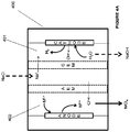
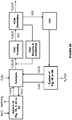
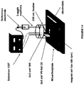
- the system 800 also includes an anode that converts metal ions from 1+ oxidation state to 2+ oxidation state.
- the Cu 2+ ions combine with chloride ions to form CuCl 2 .
- the metal chloride CuCl 2 can be then reacted with an unsaturated hydrocarbon, such as, but not limited to, ethylene to undergo reduction of the metal ion to lower oxidation state to form CuCl and dichlorohydrocarbon, such as, but not limited to, ethylene dichloride.
- the CuCl is then re-circulated back to the anode chamber for conversion to CuCl 2 .
- the HCl generated in the process of VCM formation may be circulated to one or more of the electrochemical systems described herein where HCl is used in the cathode or anode electrolyte to form hydrogen gas or water at the cathode.
- Fig. 8B an integrated electrochemical system of the invention is illustrated in combination with the VCM/PVC synthesis. Any of the electrochemical systems of the invention such as system illustrated in Fig. 1B , 2 , 4A or 5A may be used to form CuCl 2 which when reacted with ethylene results in EDC.
- the cracking of EDC with subsequent processing of VCM produces HCl which may be circulated to any of the electrochemical systems of Fig.
- the EDC product containing the metal ion may be subjected to washing step which may include rinsing with an organic solvent or passing the EDC product through a column to remove the metal ions.
- the EDC product may be purified by distillation where any of the side products such as chloral (CCl 3 CHO) and/or chloral hydrate (2,2,2-trichloroethane-1,1-diol), if formed, may be separated.
- the unsaturated hydrocarbon is benzene.
- the metal ion in the higher oxidation state such as CuCl 2 is treated with benzene to result in chlorobenzene.
- the metal ion in the higher oxidation state such as CuCl 2 is treated with acetylene to result in chloroacetylene, dichloroacetylene, vinyl chloride, dichloroethene, tetrachloroethene, or combination thereof.
- the saturated hydrocarbon in the methods and systems provided herein is of formula III which after halogenation or sulfonation (including sulfation) results in the compound of formula IV:
- the saturated hydrocarbon in the methods and systems provided herein is of formula III which after halogenation results in the compound of formula IV:
- the method includes contacting a cathode with a cathode electrolyte and forming an alkali and hydrogen gas at the cathode. In some embodiments of the method, the method includes contacting a cathode with a cathode electrolyte and forming hydrogen gas at the cathode. In some embodiments of the method, the method includes contacting a gas-diffusion cathode with a cathode electrolyte and forming an alkali at the cathode. In some embodiments of the method, the method includes contacting a gas-diffusion cathode with a cathode electrolyte and forming water at the cathode.
- methods that include contacting an anode with a metal ion in an anode electrolyte in an anode chamber; converting the metal ion from a lower oxidation state to a higher oxidation state at the anode; contacting a cathode with a cathode electrolyte; forming an alkali, water, and/or hydrogen gas at the cathode; and treating the anode electrolyte comprising the metal ion in the higher oxidation state with a saturated hydrocarbon.
- the system includes a gas-diffusion cathode with a cathode electrolyte wherein the cathode is configured to form water at the cathode.
- a gas-diffusion cathode with a cathode electrolyte wherein the cathode is configured to form water at the cathode.
- there are provided systems that include an anode chamber including an anode with a metal ion in an anode electrolyte wherein the anode is configured to convert the metal ion from a lower oxidation state to a higher oxidation state in the anode chamber; a cathode chamber including a cathode with a cathode electrolyte wherein the cathode is configured to form an alkali, water, and hydrogen gas in the cathode electrolyte; and a reactor operably connected to the anode chamber and configured to react the anode electrolyte comprising the metal ion in the higher oxidation
- the treatment of the saturated hydrocarbon with the metal ion in the higher oxidation state may be inside the cathode chamber or outside the cathode chamber.
- the treatment of the metal ion in the higher oxidation state with the saturated hydrocarbon results in chloro, bromo, iodo, or sulfohydrocarbons and the metal ion in the lower oxidation state.
- the system is configured to form the metal ion in the lower oxidation state from the metal ion in the higher oxidation state with the saturated hydrocarbon and recirculate the metal ion in the lower oxidation state back to the anode chamber.
- the anode is configured to not produce chlorine gas.
- the reactor configured to react the saturated hydrocarbon with the metal ion in the higher oxidation state is configured to not require oxygen gas and/or chlorine gas.
- the anode is configured to not produce chlorine gas and the reactor is configured to not require oxygen gas and/or chlorine gas.
- Fig. 8A can be configured for saturated hydrocarbons by replacing the unsaturated hydrocarbon with a saturated hydrocarbon.
- suitable metal ions may be used such as platinum chloride, palladium chloride, copper chloride etc.
- the remaining weight percentage is of chloroethanol and/or ethylene dichloride. In some embodiments, no chloroethanol is formed in the reaction. In some embodiments, less than 0.001wt% or less than 0.01wt% or less than 0.1wt% or less than 0.5wt% or less than 1wt% or less than 5wt% or less than 10wt% or less than 20wt% of chloroethanol is formed with the remaining product in the reaction. In some embodiments, less than 0.001wt% or less than 0.01wt% or less than 0.1wt% or less than 0.5wt% or less than 1wt% or less than 5wt% of metal ion is present in the product. In some embodiments, less than 0.001wt% or less than 0.01wt% or less than 0.1wt% of chloroethanol and/or metal ion is present in the product.
- the yield of the halogenated hydrocarbon from saturated hydrocarbon e.g. the yield of chloroethane or EDC from ethane, using the metal ions is more than 90% or more than 95% or between 90-95% or between 90-99% or between 90-99.9% by weight.
- the selectivity of the halogenated hydrocarbon from saturated hydrocarbon e.g. the yield of chloroethane or EDC from ethane, using the metal ions is more than 80% or more than 90% or between 80-99% by weight.
- the STY (space time yield) of the halogenated hydrocarbon from saturated hydrocarbon is more than 3 or more than 4 or more than 5 or between 3-5 or between 3-6 or between 3-8.
- the products, such as, but not limited to, halogenated hydrocarbon, acid, carbonate, and/or bicarbonate formed by the methods and systems of the invention are greener than the same products formed by the methods and systems conventionally known in the art.
- methods to make green halogenated hydrocarbon that include contacting an anode with an anode electrolyte; oxidizing a metal chloride from the lower oxidation state to a higher oxidation state at the anode; contacting a cathode with a cathode electrolyte; and halogenating an unsaturated or saturated hydrocarbon with the metal chloride in the higher oxidation state to produce a green halogenated hydrocarbon.
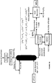
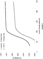
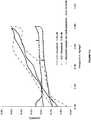
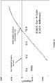
- a comparison is made between the energy required to make EDC from the chlor-alkali process and the energy required to make the EDC from the methods and systems of the invention.
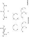
- the process of making EDC is illustrated in two parts.
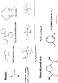
- An electrochemistry part where the copper oxidation takes place in System 1 and System 2 of the invention compared to chlorine generation taking place in the chlor-alkali process.
- a catalysis part where copper (II) chloride (generated by electrochemistry) chlorinates ethylene in System 1 and 2 and chlorine gas (generated by the chlor-alkali process) chlorinates ethylene (conventionally known) to form EDC.
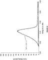
- the catalyst part of the reaction has a theoretical low barrier for each System 1 and 2 and a high barrier for the two Systems 1 and 2.
- the catalyst reaction in System 1 and System 2 can happen at the point of low barrier or at the point of high barrier or anywhere in between, depending on conditions, such as, but not limited to, concentration, size of the reactor, flow rates etc. Even if there is some energy input for the catalysis reaction in System 1 and 2, it will be offset by the significant energy saving in the electrochemical reaction such that there is a net energy saving of up to 100kJ/mol; or more than 100kJ/mol; or between 50-100kJ/mol; or between 0-100kJ/mol.
- the electrochemical systems and methods described herein are carried out in more than 5wt% water or more than 6wt% water or aqueous medium.
- the methods and systems provide an advantage of conducting the metal oxidation reaction in the electrochemical cell and reduction reaction outside the cell, all in an aqueous medium.
- a method including contacting an anode with an anode electrolyte, oxidizing a metal halide or a metal sulfate from the lower oxidation state to a higher oxidation state at the anode, contacting a cathode with a cathode electrolyte, and contacting the metal halide or a metal sulfate in the higher oxidation state with hydrogen gas in an aqueous medium to form an acid, such as, hydrochloric acid or sulfuric acid wherein the aqueous medium comprises more than 5wt% water or more than 5.5wt% or more than 6wt% or between 5-90wt% or between 5-95wt% or between 5-99wt% water or between 5.5-90wt% or between 5.5-95wt% or between 5.5-99wt% water or between 6-90wt% or between 6-95wt% or between 6-99wt% water.
- the cathode produces hydrox
- the electrochemical cell where carbon from the source of carbon (such as carbon dioxide gas or sodium carbonate/bicarbonate solution from the gas/liquid contactor) is contacted with the alkali generated by the cathode, has a theoretical cathode half cell voltage saving or theoretical total cell voltage savings of more than 0.1V, or more than 0.2V, or more than 0.5V, or more than 1V, or more than 1.5V, or between 0.1-1.5V, or between 0.1-1V, or between 0.2-1.5V, or between 0.2-1V, or between 0.5-1.5V, or between 0.5-1V as compared to the electrochemical cell where no carbon is contacted with the alkali from the cathode such as, ODC or the hydrogen gas producing cathode.
- this voltage saving is achieved with a cathode electrolyte pH of between 7-13, or between 6-12, or between 7-12, or between 7-10, or between 6-13.
- the source of carbon is any gaseous source of carbon dioxide and/or any source that provides dissolved form or solution of carbon dioxide.
- the dissolved form of carbon dioxide or solution of carbon dioxide includes carbonic acid, bicarbonate ions, carbonate ions, or combination thereof.
- the oxygen gas and/or carbon dioxide gas supplied to the cathode is from any oxygen source and carbon dioxide gas source known in the art.
- the source of oxygen gas and the source of carbon dioxide gas may be same or may be different. Some examples of the oxygen gas source and carbon dioxide gas source are as described herein.
- flue gases from combustion such as combustion of methane.
- Exhaust gases containing NOx, SOx, VOCs, particulates and Hg would incorporate these compounds along with the carbonate in the precipitated product.
- Particular multi-component gaseous streams of interest include, but not limited to, oxygen containing combustion power plant flue gas, turbo charged boiler product gas, coal gasification product gas, shifted coal gasification product gas, anaerobic digester product gas, wellhead natural gas stream, reformed natural gas or methane hydrates, and the like.
- the gas may be used both as a source of carbon dioxide as well as a source of oxygen.
- flue gases obtained from the combustion of oxygen and methane may contain oxygen gas and may provide a source of both carbon dioxide gas as well as oxygen gas.
- waste streams may be produced from a variety of different types of industrial plants.
- Suitable waste streams for the invention include waste streams, such as, flue gas, produced by industrial plants that combust fossil fuels (e.g., coal, oil, natural gas) or anthropogenic fuel products of naturally occurring organic fuel deposits (e . g ., tar sands, heavy oil, oil shale, etc.).
- a waste stream suitable for systems and methods of the invention is sourced from a coal-fired power plant, such as a pulverized coal power plant, a supercritical coal power plant, a mass burn coal power plant, a fluidized bed coal power plant.
- the waste stream is sourced from gas or oil-fired boiler and steam turbine power plants, gas or oil-fired boiler simple cycle gas turbine power plants, or gas or oil-fired boiler combined cycle gas turbine power plants.
- waste streams produced by power plants that combust syngas i.e ., gas that is produced by the gasification of organic matter, for example, coal, biomass, etc.
- waste streams from integrated gasification combined cycle (IGCC) plants are used.
- waste streams produced by Heat Recovery Steam Generator (HRSG) plants are used to produce compositions in accordance with systems and methods provided herein.
- the source of carbon is a gas/liquid contactor that provides a dissolved form or solution of carbon dioxide containing CO 2 , carbonic acid, bicarbonate ions, carbonate ions, or combination thereof.
- the solution charged with the partially or fully dissolved CO 2 is made by sparging or diffusing the CO 2 gaseous stream through slurry or solution to make a CO 2 charged water.
- the slurry or solution charged with CO 2 includes a proton removing agent obtained from the cathode electrolyte of an electrochemical cell, as described herein.
- the gas/liquid contactor may include a bubble chamber where the CO 2 gas is bubbled through the slurry or the solution containing the proton removing agent.
- the contactor may include a spray tower where the slurry or the solution containing the proton removing agent is sprayed or circulated through the CO 2 gas.
- the contactor may include a pack bed to increase the surface area of contact between the CO 2 gas and the solution containing the proton removing agent.
- the gas/liquid contactor or the absorber may contain a slurry or solution or pack bed of sodium carbonate. The CO 2 is sparged through this slurry or the solution or the pack bed where the alkaline medium facilitates dissolution of CO 2 in the solution. After the dissolution of CO 2 , the solution may contain bicarbonate, carbonate, or combination thereof.
- the alkali produced in the cathode electrolyte may be delivered to the gas/liquid contactor where the carbon dioxide gas comes into contact with the alkali.
- the carbon dioxide gas after coming into contact with the alkali may result in the formation of carbonic acid, bicarbonate ions, carbonate ions, or combination thereof.
- the dissolved form of carbon dioxide may be then delivered back to the cathode chamber where the alkali may convert the bicarbonate into the carbonate.
- the carbonate/bicarbonate mix may be then used as is for commercial purposes or is treated with divalent cations, such as, alkaline earth metal ions to form alkaline earth metal carbonates/bicarbonates.
- the source of carbon is the bicarbonate brine solution.
- the bicarbonate brine solution is as described in U.S. Provisional Application No. 61/433,641, filed on Jan. 18, 2011 and U.S. Provisional Application No. 61/408,325, filed Oct. 29, 2010 , which are both incorporated herein by reference in their entirety in the present disclosure.
- the "bicarbonate brine solution” includes any brine containing bicarbonate ions.
- the brine is a synthetic brine such as a solution of brine containing the bicarbonate, e.g., sodium bicarbonate, potassium bicarbonate, lithium bicarbonate etc.
- the alkali containing cathode electrolyte may be withdrawn from the cathode chamber and may be added to a container configured to contain the carbon from the source of carbon.
- the container may have an input for the source of carbon such as a pipe or conduit, etc. or a pipeline in communication with the gaseous stream of CO 2 , a solution containing dissolved form of CO 2 , and/or the bicarbonate brine.
- the container may also be in fluid communication with a reactor where the source of carbon, such as, e.g. bicarbonate brine solution may be produced, modified, and/or stored.
- the cathode electrolyte containing alkali, bicarbonate, and/or carbonate may be withdrawn from the cathode chamber and may be contacted with alkaline earth metal ions, as described herein, to form bicarbonate/carbonate products.
- the gas-diffusion cathodes includes such cathodes known in the art that are coated with high surface area coatings of precious metals such as gold and/or silver, precious metal alloys, nickel, and the like.
- Brackish water is water that is saltier than fresh water, but not as salty as seawater, having a salinity ranging from 0.5 to 35 ppt.
- Seawater is water from a sea or ocean and has a salinity ranging from 35 to 50 ppt.
- the saltwater source may be a naturally occurring source, such as a sea, ocean, lake, swamp, estuary, lagoon, etc., or a man-made source.
- the systems provided herein include the saltwater from terrestrial brine.
- the depleted saltwater withdrawn from the electrochemical cells is replenished with salt and re-circulated back in the electrochemical cell.
- the electrolyte including the cathode electrolyte and/or the anode electrolyte and/or the third electrolyte, such as, saltwater includes water containing more than 1% chloride content, such as, NaCl; or more than 10% NaCl; or more than 20% NaCl; or more than 30% NaCl; or more than 40% NaCl; or more than 50% NaCl; or more than 60% NaCl; or more than 70% NaCl; or more than 80% NaCl; or more than 90% NaCl; or between 1-99% NaCl; or between 1-95% NaCl; or between 1-90% NaCl; or between 1-80% NaCl; or between 1-70% NaCl; or between 1-60% NaCl; or between 1-50% NaCl; or between 1-40% NaCl; or between 1-30% NaCl; or between 1-20% NaCl; or between 1-10% NaCl; or between 10-99% NaCl; or between 10-95% NaCl; or between 10
- the above recited percentages apply to ammonium chloride, ferric chloride, sodium bromide, sodium iodide, or sodium sulfate as an electrolyte.
- the percentages recited herein include wt% or wt/wt% or wt/v%. It is to be understood that all the electrochemical systems described herein that contain sodium chloride can be replaced with other suitable electrolytes, such as, but not limited to, ammonium chloride, sodium bromide, sodium iodide, sodium sulfate, or combination thereof.
- the cathode electrolyte includes, but not limited to, sodium hydroxide, sodium bicarbonate, sodium carbonate, or combination thereof. In some embodiments, the cathode electrolyte includes, but not limited to, sodium or potassium hydroxide. In some embodiments, the cathode electrolyte includes, but not limited to, sodium hydroxide, divalent cations, or combination thereof. In some embodiments, the cathode electrolyte includes, but not limited to, sodium hydroxide, sodium bicarbonate, sodium carbonate, divalent cations, or combination thereof.
- the depleted saltwater from the cell may be circulated back to the cell.
- the cathode electrolyte includes 1-90%; 1-50%; or 1-40%; or 1-30%; or 1-15%; or 1-20%; or 1-10%; or 5-90%; or 5-50%; or 5-40%; or 5-30%; or 5-20%; or 5-10%; or 10-90%; or 10-50%; or 10-40%; or 10-30%; or 10-20%; or 15-20%; or 15-30%; or 20-30%, of the sodium hydroxide solution.
- the anode electrolyte includes 0-5 M; or 0-4.5M; or 0-4M; or 0-3.5M; or 0-3M; or 0-2.5M; or 0-2M; or 0-1.5M; or 0-1M; or 1-5M; or 1-4.5M; or 1-4M; or 1-3.5M; or 1-3M; or 1-2.5M; or 1-2M; or 1-1.5M; or 2-5M; or 2-4.5M; or 2-4M; or 2-3.5M; or 2-3M; or 2-2.5M; or 3-5M; or 3-4.5M; or 3-4M; or 3-3.5M; or 4-5M; or 4.5-5M metal ion solution.
- the anode does not form an oxygen gas.
- the anode does not form a chlorine gas.
- methods comprising contacting an anode with a metal ion in an anode electrolyte in an anode chamber; converting the metal ion from a lower oxidation state to a higher oxidation state at the anode; contacting a cathode with a cathode electrolyte in a cathode chamber; forming an alkali, water, or hydrogen gas at the cathode; and preventing migration of the metal ions from the anode electrolyte to the cathode electrolyte by using an anion exchange membrane wherein the anion exchange membrane has an ohmic resistance of less than 3 ⁇ cm 2 or less than 2 ⁇ cm 2 or less than 1 ⁇ cm 2 .
- the anion exchange membrane has an ohmic resistance of between 1-3 ⁇ cm 2 .
- methods comprising contacting an anode with a metal ion in an anode electrolyte in an anode chamber; converting the metal ion from a lower oxidation state to a higher oxidation state at the anode; contacting a cathode with a cathode electrolyte in a cathode chamber; forming an alkali, water, or hydrogen gas at the cathode; and preventing migration of the metal ions from the anode electrolyte to the cathode electrolyte by using an anion exchange membrane wherein the anion exchange membrane rejects more than 80%, or more than 90%, or more than 99%, or about 99.9% of all metal ions from the anode electrolyte.
- Also provided herein are methods comprising contacting an anode with a metal ion in an anode electrolyte in an anode chamber; converting the metal ion from a lower oxidation state to a higher oxidation state at the anode; contacting a cathode with a cathode electrolyte in a cathode chamber; forming an alkali at the cathode; separating the anode electrolyte from a brine compartment with an anion exchange membrane; separating the cathode electrolyte from the brine compartment by a cation exchange membrane; and preventing migration of the metal ions from the anode electrolyte to the brine compartment by using the anion exchange membrane that has an ohmic resistance of less than 3 ⁇ cm 2 or less than 2 ⁇ cm 2 or less than 1 ⁇ cm 2 .
- anode in contact with a metal ion in an anode electrolyte in an anode chamber wherein the anode is configured to convert the metal ion from a lower oxidation state to a higher oxidation state in the anode chamber; a cathode in contact with a cathode electrolyte in a cathode chamber wherein the cathode is configured to form an alkali in the cathode chamber; an anion exchange membrane separating the anode electrolyte from a brine compartment; and a cation exchange membrane separating the cathode electrolyte from the brine compartment, wherein the anion exchange membrane has an ohmic resistance of less than 3 ⁇ cm 2 or less than 2 ⁇ cm 2 or less than 1 ⁇ cm 2 .
- the anion exchange membrane has an ohmic resistance of between 1-3 ⁇ cm 2 .
- systems comprising contacting an anode in contact with a metal ion in an anode electrolyte in an anode chamber wherein the anode is configured to convert the metal ion from a lower oxidation state to a higher oxidation state in the anode chamber; a cathode in contact with a cathode electrolyte in a cathode chamber wherein the cathode is configured to form an alkali in the cathode chamber; an anion exchange membrane separating the anode electrolyte from a brine compartment; and a cation exchange membrane separating the cathode electrolyte from the brine compartment, wherein the anion exchange membrane rejects more than 80%, or more than 90%, or more than 99%, or about 99.9% of all metal ions from the anode electrolyte.
- an anion exchange membrane that is more restrictive and thus allows migration of one species of anions while restricting the migration of another species of anions may be used as, e.g., an anion exchange membrane that allows migration of chloride ions into the anode electrolyte from the cathode electrolyte while restricting migration of hydroxide ions from the cathode electrolyte into the anode electrolyte, may be used.
- an anion exchange membrane that allows migration of chloride ions into the anode electrolyte from the cathode electrolyte while restricting migration of hydroxide ions from the cathode electrolyte into the anode electrolyte.
- Such restrictive cation and/or anion exchange membranes are commercially available and can be selected by one ordinarily skilled in the art.
- a system comprising one or more anion exchange membrane, and cation exchange membranes located between the anode and the cathode.
- the membranes should be selected such that they can function in an acidic and/or basic electrolytic solution as appropriate.
- Other desirable characteristics of the membranes include high ion selectivity, low ionic resistance, high burst strength, and high stability in an acidic electrolytic solution in a temperature range of 0°C to 100°C or higher, or a alkaline solution in similar temperature range may be used.
- it is desirable that the ion exchange membrane prevents the transport of the metal ion from the anolyte to the catholyte.
- a membrane that is stable in the range of 0°C to 90°C; or 0°C to 80°C; or 0°C to 70°C; or 0°C to 60°C; or 0°C to 50°C; or 0°C to 40°C, or 0°C to 30°C, or 0°C to 20°C, or 0°C to 10°C, or higher may be used.
- a membrane that is stable in the range of 0°C to 90°C; or 0°C to 80°C; or 0°C to 70°C; or 0°C to 60°C; or 0°C to 50°C; or 0°C to 40°C, but unstable at higher temperature may be used.
- the membrane may be stable and functional for a desirable length of time in the system, e.g., several days, weeks or months or years at temperatures in the range of 0°C to 90°C; or 0°C to 80°C; or 0°C to 70°C; or 0°C to 60°C; or 0°C to 50°C; or 0°C to 40°C; or 0°C to 30°C; or 0°C to 20°C; or 0°C to 10°C, and higher and/or lower.
- the membranes may be stable and functional for at least 1 day, at least 5 days, 10 days, 15 days, 20 days, 100 days, 1000 days, 5-10 years, or more in electrolyte temperatures at 100°C, 90°C, 80°C, 70°C, 60°C, 50°C, 40°C, 30°C, 20°C, 10°C, 5°C and more or less.
- Scattered through membranes may be ionic channels including acid groups. These ionic channels may extend from the internal surface of the matrix to the external surface and the acid groups may readily bind water in a reversible reaction as water-of-hydration. This binding of water as water-of-hydration may follow first order reaction kinetics, such that the rate of reaction is proportional to temperature. Consequently, membranes can be selected to provide a relatively low ohmic and ionic resistance while providing for improved strength and resistance in the system for a range of operating temperatures.
- the carbon from the source of carbon when contacted with the cathode electrolyte inside the cathode chamber, reacts with the hydroxide ions and produces water and carbonate ions, depending on the pH of the cathode electrolyte.
- the addition of the carbon from the source of carbon to the cathode electrolyte may lower the pH of the cathode electrolyte.
- the pH of the cathode electrolyte may be adjusted and in some embodiments is maintained between 6 and 12; between 7 and 14 or greater; or between 7 and 13; or between 7 and 12; or between 7 and 11; or between 7 and 10; or between 7 and 9; or between 7 and 8; or between 8 and 14 or greater; or between 8 and 13; or between 8 and 12; or between 8 and 11; or between 8 and 10; or between 8 and 9; or between 9 and 14 or greater; or between 9 and 13; or between 9 and 12; or between 9 and 11; or between 9 and 10; or between 10 and 14 or greater; or between 10 and 13; or between 10 and 12; or between 10 and 11; or between 11 and 14 or greater; or between 11 and 13; or between 11 and 12; or between 12 and 14 or greater; or between 12 and 13; or between 13 and 14 or greater.
- the pH of the cathode electrolyte may be adjusted to any value between 7 and 14 or greater, a pH less than 12, a pH 7.0, 7.5, 8.0, 8.5, 9.0, 9.5, 10.0, 10.5, 11.0, 11.5, 12.0, 12.5, 13.0, 13.5, 14.0, and/or greater.
- the pH of the anode electrolyte may be adjusted to a value between 0 and 7, including 0, 0.5, 1.0, 1.5, 2.0, 2.5, 3.0, 3.5, 4.0, 4.5, 5.0, 5.5, 6.0, 6.5 and 7, depending on the desired operating voltage across the anode and cathode.
- the system is configured to produce a pH difference of at least 4 pH units; at least 5 pH units; at least 6 pH units; at least 7 pH units; at least 8 pH units; at least 9 pH units; at least 10 pH units; at least 11 pH units; at least 12 pH units; at least 13 pH units; at least 14 pH units; or between 4-12 pH units; or between 4-11 pH units; or between 4-10 pH units; or between 4-9 pH units; or between 4-8 pH units; or between 4-7 pH units; or between 4-6 pH units; or between 4-5 pH units; or between 3-12 pH units; or between 3-11 pH units; or between 3-10 pH units; or between 3-9 pH units; or between 3-8 pH units; or between 3-7 pH units; or between 3-6 pH units; or between 3-5 pH units; or between 3-4 pH units; or between 5-12 pH units; or between 5-11 pH units; or between 5-10 pH units; or between 5-9 pH units; or between 5-8 pH units; or between 5-7 pH units; or between 5-6 pH units; or between 6-12 pH
- the "divalent cation" as used herein, includes any solid or solution that contains divalent cations, such as, alkaline earth metal ions or any aqueous medium containing alkaline earth metals.
- the alkaline earth metals include calcium, magnesium, strontium, barium, etc. or combinations thereof.
- the divalent cations e . g ., alkaline earth metal cations such as Ca 2+ and Mg 2+ ) may be found in industrial wastes, seawater, brines, hard water, minerals, and many other suitable sources.
- the alkaline-earth-metal-containing water includes fresh water or saltwater, depending on the method employing the water.
- gypsum (e.g. from Solvay process) provides a source of divalent cation such as, but not limited to, calcium ions. After the precipitation of the calcium carbonate/bicarbonate using the carbonate/bicarbonate solution from the cathode chamber and the calcium from gypsum, the supernatant containing sodium sulfate may be circulated to the electrochemical systems described herein.
- the sodium sulfate solution may be used in combination with metal sulfate such as copper sulfate such the Cu(I) ions are oxidized to Cu (II) ions in the anode chamber and are used further for the sulfonation of hydrogen gases or for the sulfonation of unsaturated or saturated hydrocarbons.
- metal sulfate such as copper sulfate
- the electrochemical system is fully integrated with the precipitation process.
- gypsum as a source of calcium is described in US Provisional Application No. 61/514,879, filed August 3, 2011 , which is fully incorporate herein by reference in its entirety.
- waste streams from various industrial processes provide for convenient sources of cations (as well as in some cases other materials useful in the process, e.g., metal hydroxide).
- waste streams include, but are not limited to, mining wastes; fossil fuel burning ash (e.g., fly ash, bottom ash, boiler slag); slag (e.g., iron slag, phosphorous slag); cement kiln waste ( e .
- cement kiln dust oil refinery/petrochemical refinery waste (e.g., oil field and methane seam brines); coal seam wastes (e.g., gas production brines and coal seam brine); paper processing waste; water softening waste brine (e.g., ion exchange effluent); silicon processing wastes; agricultural waste; metal finishing waste; high pH textile waste; and caustic sludge.
- oil refinery/petrochemical refinery waste e.g., oil field and methane seam brines
- coal seam wastes e.g., gas production brines and coal seam brine
- paper processing waste e.g., water softening waste brine (e.g., ion exchange effluent)
- silicon processing wastes e.g., silicon processing wastes
- agricultural waste metal finishing waste
- high pH textile waste high pH textile waste
- caustic sludge caustic sludge.
- the aqueous solution of cations include calcium and/or magnesium in amounts ranging from 10-50,000 ppm; or 10-10,000 ppm; or 10-5,000 ppm; or 10-1,000 ppm; or 10-100 ppm; or 50-50,000 ppm; or 50-10,000 ppm; or 50-1,000 ppm; or 50-100 ppm; or 100-50,000 ppm; or 100-10,000 ppm; or 100-1,000 ppm; or 100-500 ppm; or 1,000-50,000 ppm; or 1,000-10,000 ppm; or 5,000-50,000 ppm; or 5,000-10,000 ppm; or 10,000-50,000 ppm.
- the precipitate obtained after the contacting of the carbon from the source of carbon with the cathode electrolyte and the divalent cations includes, but is not limited to, calcium carbonate, magnesium carbonate, calcium bicarbonate, magnesium bicarbonate, calcium magnesium carbonate, or combination thereof.
- the precipitate may be subjected to one or more of steps including, but not limited to, mixing, stirring, temperature, pH, precipitation, residence time of the precipitate, dewatering of precipitate, washing precipitate with water, ion ratio, concentration of additives, drying, milling, grinding, storing, aging, and curing, to make the carbonate composition of the invention.
- the precipitation conditions are such that the carbonate products are metastable forms, such as, but not limited to vaterite, aragonite, amorphous calcium carbonate, or combination thereof.
- the precipitator 1301 can be a tank or a series of tanks.
- Contact protocols include, but are not limited to, direct contacting protocols, e . g ., flowing the volume of water containing cations, e . g . alkaline earth metal ions through the volume of cathode electrolyte containing sodium hydroxide; concurrent contacting means, e . g ., contact between unidirectionally flowing liquid phase streams; and countercurrent means, e . g ., contact between oppositely flowing liquid phase streams, and the like.
- contact may be accomplished through use of infusers, bubblers, fluidic Venturi reactor, sparger, gas filter, spray, tray, or packed column reactors, and the like, as may be convenient.
- the contact is by spray. In some embodiments, the contact is through packed column.
- the carbon from the source of carbon is added to the source of cations and the cathode electrolyte containing hydroxide. In some embodiments, the source of cations and the cathode electrolyte containing alkali is added to the carbon from the source of carbon. In some embodiments, both the source of cations and the carbon from the source of carbon are simultaneously added to the cathode electrolyte containing alkali in the precipitator for precipitation.
- the precipitator 1301 containing the solution of calcium carbonate, magnesium carbonate, calcium bicarbonate, magnesium bicarbonate, calcium magnesium carbonate, or combination thereof is subjected to precipitation conditions.
- carbonate compounds which may be amorphous or crystalline, are precipitated. These carbonate compounds may form a reaction product including carbonic acid, bicarbonate, carbonate, or mixture thereof.
- the carbonate precipitate may be the self-cementing composition and may be stored as is in the mother liquor or may be further processed to make the cement products. Alternatively, the precipitate may be subjected to further processing to give the hydraulic cement or the supplementary cementitious materials (SCM) compositions.
- SCM supplementary cementitious materials
- the one or more conditions or one or more precipitation conditions of interest include those that change the physical environment of the water to produce the desired precipitate product.
- Such one or more conditions or precipitation conditions include, but are not limited to, one or more of temperature, pH, precipitation, dewatering or separation of the precipitate, drying, milling, and storage.
- the temperature of the water may be within a suitable range for the precipitation of the desired composition to occur.
- the temperature of the water may be raised to an amount suitable for precipitation of the desired carbonate compound(s) to occur.
- the temperature of the water may be from 5 to 70°C, such as from 20 to 50°C, and including from 25 to 45°C.
- a given set of precipitation conditions may have a temperature ranging from 0 to 100°C
- the temperature may be raised in certain embodiments to produce the desired precipitate.
- the temperature is raised using energy generated from low or zero carbon dioxide emission sources, e.g., solar energy source, wind energy source, hydroelectric energy source, etc.
- the residence time of the precipitate in the precipitator before the precipitate is removed from the solution may vary.
- the residence time of the precipitate in the solution is more than 5 seconds, or between 5 seconds-1 hour, or between 5 seconds-1 minute, or between 5 seconds to 20 seconds, or between 5 seconds to 30 seconds, or between 5 seconds to 40 seconds.
- the residence time of the precipitate may affect the size of the particle. For example, a shorter residence time may give smaller size particles or more disperse particles whereas longer residence time may give agglomerated or larger size particles.
- the residence time in the process of the invention may be used to make small size as well as large size particles in a single or multiple batches which may be separated or may remain mixed for later steps of the process.
- a set of conditions to produce the desired precipitate from the water include, but are not limited to, the water's temperature and pH, and in some instances the concentrations of additives and ionic species in the water. Precipitation conditions may also include factors such as mixing rate, forms of agitation such as ultrasonics, and the presence of seed crystals, catalysts, membranes, or substrates. In some embodiments, precipitation conditions include supersaturated conditions, temperature, pH, and/or concentration gradients, or cycling or changing any of these parameters.
- the protocols employed to prepare carbonate compound precipitates according to the invention may be batch or continuous protocols. It will be appreciated that precipitation conditions may be different to produce a given precipitate in a continuous flow system compared to a batch system.
- the resultant precipitated carbonate composition may be separated from the mother liquor or dewatered to produce the precipitate product, as illustrated at step 1302 of Fig. 13 .
- the precipitate is left as is in the mother liquor or mother supernate and is used as a cementing composition. Separation of the precipitate can be achieved using any convenient approach, including a mechanical approach, e . g ., where bulk excess water is drained from the precipitated, e . g ., either by gravity alone or with the addition of vacuum, mechanical pressing, by filtering the precipitate from the mother liquor to produce a filtrate, etc. Separation of bulk water produces a wet, dewatered precipitate.
- the dewatering station may be any number of dewatering stations connected to each other to dewater the slurry (e.g., parallel, in series, or combination thereof).
- the above protocol results in the production of slurry of the precipitate and mother liquor.
- This precipitate in the mother liquor and/or in the slurry may give the self-cementing composition.
- a portion or whole of the dewatered precipitate or the slurry is further processed to make the hydraulic cement or the SCM compositions.
- Embodiments may include treatment of the mother liquor, where the mother liquor may or may not be present in the same composition as the product.
- the resultant mother liquor of the reaction may be disposed of using any convenient protocol. In certain embodiments, it may be sent to a tailings pond 1307 for disposal. In certain embodiments, it may be disposed of in a naturally occurring body of water, e . g ., ocean, sea, lake or river.
- the mother liquor is returned to the source of feedwater for the methods of invention, e . g ., an ocean or sea.
- the mother liquor may be further processed, e . g ., subjected to desalination protocols, as described further in United States Application Serial No. 12/163,205, filed June 27, 2008 ; the disclosure of which is herein incorporated by reference in the present disclosure.
- the resultant dewatered precipitate is then dried to produce the carbonate composition of the invention, as illustrated at step 1304 of Fig. 13 .
- Drying can be achieved by air drying the precipitate. Where the precipitate is air dried, air drying may be at a temperature ranging from -70 to 120°C, as desired. In certain embodiments, drying is achieved by freeze-drying (i.e., lyophilization), where the precipitate is frozen, the surrounding pressure is reduced and enough heat is added to allow the frozen water in the material to sublime directly from the frozen precipitate phase to gas. In yet another embodiment, the precipitate is spray dried to dry the precipitate, where the liquid containing the precipitate is dried by feeding it through a hot gas (such as the gaseous waste stream from the power plant), e .
- a hot gas such as the gaseous waste stream from the power plant
- the drying station may include a filtration element, freeze drying structure, spray drying structure, etc.
- the drying step may discharge air and fines 1306.
- the calcium carbonate precipitate formed by the methods and system of the invention is in a metastable form including but not limited to, vaterite, aragonite, amorphous calcium carbonate, or combination thereof.
- the calcium carbonate precipitate formed by the methods and system of the invention is in a metastable form including but not limited to, vaterite, amorphous calcium carbonate, or combination thereof.
- the vaterite containing composition of calcium carbonate, after coming into contact with water converts to a stable polymorph form such as aragonite, calcite, or combination thereof with a high compressive strength.
- the carbonate composition or the cementitous composition, thus formed, has elements or markers that originate from the carbon from the source of carbon used in the process.
- the carbonate composition after setting, and hardening has a compressive strength of at least 14 MPa; or at least 16 MPa; or at least 18 MPa; or at least 20 MPa; or at least 25 MPa; or at least 30 MPa; or at least 35 MPa; or at least 40 MPa; or at least 45 MPa; or at least 50 MPa; or at least 55 MPa; or at least 60 MPa; or at least 65 MPa; or at least 70 MPa; or at least 75 MPa; or at least 80 MPa; or at least 85 MPa; or at least 90 MPa; or at least 95 MPa; or at least 100 MPa; or from 14-100 MPa; or from 14-80 MPa; or from 14-75 MPa; or from 14-70 MPa; or from 14-65 MPa; or from 14-60 MPa; or from 14-55 MPa; or from 14-50 MPa;
- the composition after setting, and hardening has a compressive strength of 14 MPa to 40 MPa; or 17 MPa to 40 MPa; or 20 MPa to 40 MPa; or 30 MPa to 40 MPa; or 35 MPa to 40 MPa.
- the compressive strengths described herein are the compressive strengths after 1 day, or 3 days, or 7 days, or 28 days.
- This example illustrates the highest current density achieved at 0V in different electrochemical systems.
- the conditions used for this experiment were: anode: 6cm 2 Pt foil; cathode: 6cm 2 oxygen depolarized cathode; anolyte: 0.5M Cr 2+ solvated with ultrapure deionized water; brine: 15.6wt% NaCl solvated with ultrapure deionized water; catholyte: 10wt% NaOH solvated with ultrapure deionized water.
- Solution temperatures were held constant at 70°C and re-circulated in the cell at 400 rpm using an LS16 sized peristaltic tubing.
- the electrochemical systems used in this experiment were the electrochemical system 500 of Fig.
- the catholyte was bubbled with CO 2 until the pH reached less than 12 and around 10.
- adjusting the pH of the catholyte via CO 2 injection improved the overall performance as it improved the voltage by 300mV at 150mA/cm 2 .
- the cathode reaction produced hydrogen that can be used for metal ion regeneration through the use of hydrogenation (as illustrated in Fig. 6 ).
- the current was increased galvanostatically and the resulting cell voltage was recorded.
- This example illustrates the hydrogenation of the chromium ion in the higher oxidation state to form the chromium ion in the lower oxidation state and hydrochloric acid.
- This example illustrates the hydrogenation of the copper ion in the higher oxidation state to form the copper ion in the lower oxidation state and hydrochloric acid.
- propylene was added to the container to raise the pressure from the autogenous pressure, mostly owing from water vapor, to a pressure of 130psig. After 15 minutes, more propylene was added to raise the pressure from 120psig to 140psig. After an additional 15 minutes, the pressure was 135psig.
- the reactor was cooled to 14°C, depressurized, and opened. Ethyl acetate was used to rinse the reactor parts and then was used as the extraction solvent. The product was analyzed by gas chromatography which showed 0.203g of 1,2-dichloropropane that was recovered in the ethyl acetate phase.
- TMEDA N,N,N,N-tetramethylethylenediamine
- a half cell reaction was carried out using the metal-ligand solution of Example 6 and the set up of Example 1.
- the working electrode for the half cell reaction was 4cm 2 Pt Gauze 52 mesh anode; the counter electrode was 6cm 2 Pt foil; and the reference electrode was Saturated Calomel electrode (SCE).
- SCE Saturated Calomel electrode
- the solution in the beaker was kept at 70°C.
- a solution contained 2.5M NaCl, 1.0M CuCl 2 , and 0.5M CuCl and no ligand.
- the solution contained 2.5M NaCl, 1.0M CuCl 2 , 0.5M CuCl, and 2.2M TMEDA (Example 6).
- a voltage savings of about 200mV was observed at 150mA/cm 2 when the ligand was used in the metal solution.
- This example illustrates effect of selection of AEM on the prevention of the crossover of the metal ions through the AEM to the middle chamber. This example also illustrates the selection of AEM that prevents crossover of metal ions, fouling of the membrane, and increase in resistance.
- a series of anion exchange membranes were tested in this experiment including ACS, ACM and AHA from Astom Corporation, FAB and FAP from FuMaTech, and DSV from Asahi Glass.
- the AEM was sandwiched in between an anolyte containing 3M CuCl 2 /1M CuCl/4.6M NaCl and a chamber containing 4.6M NaCl electrolyte.
- a standard three-electrode setup was used including a platinum gauze working/counter electrode and saturated calomel electrode (SCE) reference. An additional two SCE's were placed in a luggin capillary on either side of the membrane.
- SCE saturated calomel electrode
- a two Pt-foil electrode setup was used.
- the AHA membrane was sandwiched in between a saturated brine solution and the Cu-base electrolyte.
- the frequency range was between 15,000Hz-0.001Hz at an amplitude of 20mA and a DC signal of 150 mA/cm 2 .
- the cell was run with and without the AHA and the difference in high frequency x-intercepts represented the AEM area resistance.
- Solution A is: 4.6M NaCl: solution B is: 0.5M CuCl/2.5M NaCl; solution C is: 4.5M CuCl 2 /0.5M CuCl/2.5M NaCl; and solution D is: 4.5M CuCl 2 /0.5M CuCl.
- Table III Summary of results for resistance measurements of AHA in different Cu-base solutions Chemistry ⁇ cm 2 solution ⁇ cm 2 AHA + solution ⁇ cm 2 AHA V loss @ 150mA/cm 2 A-membrane-A 1.28 3.14 1.86 0.28 A-membrane-B 1.28/1.77 3.58 1.81-2.06 0.272-0.308 A-membrane-C 1.28/2.8 4.96 2.16-2.92 0.324-0.438 A-membrane-D 1.28/3.14 7.51 4.37-5.3 0.656-0.795
- solution B with no CuCl 2 had a resistance similar to plain NaCl with no added CuClx.
- Solution C showed a voltage loss between 320-430mV. Adding CuCl 2 into the anolyte produced a small increase in resistance. It is contemplated that this could be due to the change in solution resistance through the AEM.
- Solution D which is equivalent to solution C with no NaCl, showed over a 2-fold increase in voltage loss. It is contemplated that there may be a change in copper speciation leading to an increase in resistance.
- a full cell configuration was used to measure the Cu-species transport through the AEM.
- a solution of 4.5M CuCl 2 /0.5M CuCl/2.5M NaCl was fed into the anolyte, 4.6M NaCl was fed into the intermediate compartment, and 10 wt% NaOH was fed into the catholyte at 70°C.
- the cell was operated at 150mA/cm 2 and 300mA/cm 2 at a series of flow rates. For each flow rate (such as 20ml/min, 40ml/min, etc.) the copper ion concentration was measured pre testing and after running the cell for 30 min. UV-VIS was used to measure the total Cu in the brine solution in the intermediate compartment, pre and post testing.
- Fig. 25A and Table IV illustrate the specific ligand, the amount of the ligand, the reaction conditions, and the amount of main products formed. A comparative example without ligand is included as well.
- Fig. 25B illustrates other examples of the ligands that can be used in the catalytic reaction.
- Table IV demonstrates that the ligand not only improves the yield of EDC in the reaction but also improves the selectivity.
- Table IV Ligand # Ligand amount in mmol EDC by GC in mg/ml ClEtOH by GC in mg/ml Selectivity no ligand N/A 10.20 1.53 0.87 2 0.5 6.89 1.33 0.84 2 2 3.87 1.15 0.77 3 0.5 8.20 1.48 0.85 3 2 11.56 1.73 0.87 4 0.5 7.84 1.38 0.85 4 2 1.75 0.46 0.79 5 0.5 7.75 1.36 0.85 5 2 2.11 0.70 0.75 6 0.5 15.49 1.78 0.90 6 2 16.29 1.98 0.89 7 0.5 13.42 1.44 0.90 8 0.5 6.88 0.97 0.88 10 0.5 10.14 1.66 0.86 10 2 15.96 1.59 0.91 11 0.5 11.10 1.93 0.85 11 2 12.22 2.01 0.86 12 0.5 9.75 1.50 0.87 12 2 1.06 0.45 0.70
- a full cell reaction was carried out using sodium chloride and ammonium chloride as electrolytes.
- the components of the cell were commercially available and included Pt guaze anode; PGM mesh cathode; anion exchange membrane as AHA from Neosepta; and the cation exchange membrane as Dupont N2100.
- the catholyte was 10wt% NaOH.
- the anolyte was 4.5M CuCl 2 / 0.5M CuCl/ 2.5M NaCl and in the 2nd experiment, the anolyte was 4.5M CuCl 2 / 0.5M CuCl/ 2.5M NH 4 Cl.
- the solution in the cell was kept at 70°C. Fig.
- This experiment was related to the conditioning of the AEM before the start of the electrochemical cell.
- Initial solutions introduced into the full cell were 0.5M Na 2 SO 4 as the anolyte, 4.6M NaCl into the intermediate compartment, and 10wt% NaOH as the catholyte.
- the membranes were FAS from FuMaTech as the anion exchange membrane and N2100 from Dupont as the cation exchange membrane.
- the cell was then run at 300 mA/cm 2 . At this point, the anodic reaction was oxygen evolution and the cathodic reaction was water reduction. As illustrated in Fig. 28 , the initial overall cell voltage of about 4.5V was seen.
- a valve was switched and the Na 2 SO 4 was flushed out of the cell and the anolyte (4.5M CuCl 2 /0.5M CuCl/2.5M NaCl) was then fed into the anode chamber.
- the cell was constantly held at 300mA/cm 2 during this time.
- the anodic reaction now was copper oxidation, as illustrated in Fig. 28 as the sudden drop in cell voltage.
- the black curve shows the voltage when the copper electrolyte was introduced into the cell (with no initial voltage stabilization by sodium sulfate) before a voltage was applied. There was about a 200mV voltage savings when Na 2 SO 4 was used at the start-up and the voltage was significantly more stable for the duration of the test.
- the conditioning of the AEM at the operating current density prior to introducing the copper-base electrolyte may be beneficial for voltage and stability.
- This example illustrates the re-circulation of the Cu(I) solution generated by a catalysis reactor to the electrochemical cell containing a PtIr gauze electrode.
- a solution containing 4.5M Cu(II), 0.1M Cu(I), and 1.0M NaCl was charged to the Parr bomb reactor for a 60 min. reaction at 160°C and 330 psi.
- the same solution was tested via anodic cyclic voltammetry (CV) before and after the catalysis run to look for effects of organic residues such as EDC or residual extractant on anode performance.
- CV experiment was conducted at 70°C with 10mVs -1 scan rate for five cycles, 0.3 to 0.8V vs. saturated calomel electrode (SCE).
- This example illustrates the re-circulation of the Cu(I) solution containing the ligand from the catalysis reactor to the electrochemical cell.
- a 2 mL sample of the catalyst solution tested in the catalysis high throughput reactor was sent to a three-electrode micro-cell for electrochemical screening via anodic cyclic voltammetry (CV) to determine if a correlation existed between redox potential and catalysis performance.
- the ligands were: and
- the catalyst solution contained 5.0M Cu(II)/0.5M Cu(I)/0.5M or 1M ligand/1M NaCl. These ligand solutions were tested in the anodic micro-half-cell via cyclic voltammetry to measure redox potential.
- the micro-cell consisted of a PtIr foil working electrode, Pt foil counter electrode, and a capillary bridge to a Ag/AgCl microelectrode as reference. All electrodes were sealed into a 4mL vial, heated to 70°C and stirred at 100 rpm. Each CV experiment was conducted at 70°C with 10 mV s -1 scan rate for five cycles, 0.3 to 0.8 V vs. Ag/AgCl reference electrode.
- Table V below shows the voltages obtained for five catalytic re-circulated solutions. The results indicated that ligand enhanced the EDC production and the re-circulated catalytic solution containing the ligand to the electrochemical cell, reduced the electrochemical voltage. Table V shows that the redox potential of samples containing ligand #1 (samples A and B) had a reduced redox potential compared to the equivalent ligand free system E. Samples C and D that contained the ligand #2 had a similar redox potential compared to the ligand free sample E. Table V Sample Ligand # Concentration CV A 1 0.5 0.684 B 1 1 0.676 C 2 1 0.739 D 2 0.5 0.737 E No ligand N/A 0.728
- an electrochemical cell including an anode and a cathode where the anode is contacted with a metal ion that converts the metal ion from a lower oxidation state to a higher oxidation state.
- the metal ion in the higher oxidation state is reacted with hydrogen gas, an unsaturated hydrocarbon, and/or a saturated hydrocarbon to form products.
Landscapes
- Chemical & Material Sciences (AREA)
- Organic Chemistry (AREA)
- Chemical Kinetics & Catalysis (AREA)
- Engineering & Computer Science (AREA)
- Materials Engineering (AREA)
- Electrochemistry (AREA)
- Metallurgy (AREA)
- Inorganic Chemistry (AREA)
- Health & Medical Sciences (AREA)
- Medicinal Chemistry (AREA)
- Polymers & Plastics (AREA)
- Electrolytic Production Of Non-Metals, Compounds, Apparatuses Therefor (AREA)
- Electrodes For Compound Or Non-Metal Manufacture (AREA)
- Addition Polymer Or Copolymer, Post-Treatments, Or Chemical Modifications (AREA)
- Primary Cells (AREA)
- Battery Electrode And Active Subsutance (AREA)
- Inorganic Compounds Of Heavy Metals (AREA)
Applications Claiming Priority (8)
| Application Number | Priority Date | Filing Date | Title |
|---|---|---|---|
| US201161488079P | 2011-05-19 | 2011-05-19 | |
| US201161499499P | 2011-06-21 | 2011-06-21 | |
| US201161515474P | 2011-08-05 | 2011-08-05 | |
| US201161546461P | 2011-10-12 | 2011-10-12 | |
| US201161552701P | 2011-10-28 | 2011-10-28 | |
| US201261597404P | 2012-02-10 | 2012-02-10 | |
| US201261617390P | 2012-03-29 | 2012-03-29 | |
| EP12785945.2A EP2710650B1 (fr) | 2011-05-19 | 2012-05-17 | Systèmes et procédés électrochimiques à hydroxyde utilisant une oxydation de métal |
Related Parent Applications (2)
| Application Number | Title | Priority Date | Filing Date |
|---|---|---|---|
| EP12785945.2A Division EP2710650B1 (fr) | 2011-05-19 | 2012-05-17 | Systèmes et procédés électrochimiques à hydroxyde utilisant une oxydation de métal |
| EP12785945.2A Division-Into EP2710650B1 (fr) | 2011-05-19 | 2012-05-17 | Systèmes et procédés électrochimiques à hydroxyde utilisant une oxydation de métal |
Publications (1)
| Publication Number | Publication Date |
|---|---|
| EP3173509A1 true EP3173509A1 (fr) | 2017-05-31 |
Family
ID=47174124
Family Applications (2)
| Application Number | Title | Priority Date | Filing Date |
|---|---|---|---|
| EP12785945.2A Active EP2710650B1 (fr) | 2011-05-19 | 2012-05-17 | Systèmes et procédés électrochimiques à hydroxyde utilisant une oxydation de métal |
| EP16188593.4A Withdrawn EP3173509A1 (fr) | 2011-05-19 | 2012-05-17 | Systèmes et procédés électrochimiques utilisant une oxydation de métal |
Family Applications Before (1)
| Application Number | Title | Priority Date | Filing Date |
|---|---|---|---|
| EP12785945.2A Active EP2710650B1 (fr) | 2011-05-19 | 2012-05-17 | Systèmes et procédés électrochimiques à hydroxyde utilisant une oxydation de métal |
Country Status (13)
| Country | Link |
|---|---|
| US (10) | US9187835B2 (fr) |
| EP (2) | EP2710650B1 (fr) |
| JP (4) | JP6183961B2 (fr) |
| KR (3) | KR101813930B1 (fr) |
| CN (2) | CN105220174B (fr) |
| AU (2) | AU2012255123B2 (fr) |
| BR (1) | BR112013029590B1 (fr) |
| CA (2) | CA2836581C (fr) |
| EA (1) | EA024710B1 (fr) |
| MY (2) | MY170344A (fr) |
| SA (1) | SA112330516B1 (fr) |
| TW (1) | TWI537424B (fr) |
| WO (1) | WO2012158969A1 (fr) |
Families Citing this family (79)
| Publication number | Priority date | Publication date | Assignee | Title |
|---|---|---|---|---|
| WO2010088524A2 (fr) | 2009-01-29 | 2010-08-05 | Princeton University | Transformation du dioxyde de carbone en produits organiques |
| US8845877B2 (en) | 2010-03-19 | 2014-09-30 | Liquid Light, Inc. | Heterocycle catalyzed electrochemical process |
| US8500987B2 (en) | 2010-03-19 | 2013-08-06 | Liquid Light, Inc. | Purification of carbon dioxide from a mixture of gases |
| US8721866B2 (en) | 2010-03-19 | 2014-05-13 | Liquid Light, Inc. | Electrochemical production of synthesis gas from carbon dioxide |
| US8592633B2 (en) | 2010-07-29 | 2013-11-26 | Liquid Light, Inc. | Reduction of carbon dioxide to carboxylic acids, glycols, and carboxylates |
| US8845878B2 (en) | 2010-07-29 | 2014-09-30 | Liquid Light, Inc. | Reducing carbon dioxide to products |
| US8961774B2 (en) | 2010-11-30 | 2015-02-24 | Liquid Light, Inc. | Electrochemical production of butanol from carbon dioxide and water |
| US8568581B2 (en) | 2010-11-30 | 2013-10-29 | Liquid Light, Inc. | Heterocycle catalyzed carbonylation and hydroformylation with carbon dioxide |
| US9090976B2 (en) | 2010-12-30 | 2015-07-28 | The Trustees Of Princeton University | Advanced aromatic amine heterocyclic catalysts for carbon dioxide reduction |
| US9200375B2 (en) | 2011-05-19 | 2015-12-01 | Calera Corporation | Systems and methods for preparation and separation of products |
| SA112330516B1 (ar) * | 2011-05-19 | 2016-02-22 | كاليرا كوربوريشن | انظمة وطرق هيدروكسيد كهروكيميائية مستخدمة لأكسدة المعدن |
| AU2012278948A1 (en) | 2011-07-06 | 2014-01-16 | Liquid Light, Inc. | Carbon dioxide capture and conversion to organic products |
| WO2013082110A1 (fr) * | 2011-12-02 | 2013-06-06 | Bio2Electric, Llc | Réacteur, procédé, et système pour l'oxydation de courants gazeux |
| CN104271810B (zh) * | 2012-03-29 | 2017-05-03 | 卡勒拉公司 | 利用金属氧化的电化学氢氧化物系统和方法 |
| US9267212B2 (en) | 2012-07-26 | 2016-02-23 | Liquid Light, Inc. | Method and system for production of oxalic acid and oxalic acid reduction products |
| US10329676B2 (en) | 2012-07-26 | 2019-06-25 | Avantium Knowledge Centre B.V. | Method and system for electrochemical reduction of carbon dioxide employing a gas diffusion electrode |
| US9175407B2 (en) | 2012-07-26 | 2015-11-03 | Liquid Light, Inc. | Integrated process for producing carboxylic acids from carbon dioxide |
| US20130105304A1 (en) | 2012-07-26 | 2013-05-02 | Liquid Light, Inc. | System and High Surface Area Electrodes for the Electrochemical Reduction of Carbon Dioxide |
| US8641885B2 (en) | 2012-07-26 | 2014-02-04 | Liquid Light, Inc. | Multiphase electrochemical reduction of CO2 |
| US8821709B2 (en) | 2012-07-26 | 2014-09-02 | Liquid Light, Inc. | System and method for oxidizing organic compounds while reducing carbon dioxide |
| DE102012017306A1 (de) * | 2012-09-03 | 2014-03-06 | Thyssenkrupp Uhde Gmbh | Elektrochemische Zelle vom Durchflusstyp |
| WO2014043651A2 (fr) | 2012-09-14 | 2014-03-20 | Liquid Light, Inc. | Cellule électrochimique à haute pression et processus pour la réduction électrochimique de dioxyde de carbone |
| US9664385B2 (en) * | 2012-09-17 | 2017-05-30 | Phillips 66 Company | Process for enabling carbon-capture from existing combustion processes |
| TWI633206B (zh) * | 2013-07-31 | 2018-08-21 | 卡利拉股份有限公司 | 使用金屬氧化物之電化學氫氧化物系統及方法 |
| DE102014111781B4 (de) * | 2013-08-19 | 2022-08-11 | Korea Atomic Energy Research Institute | Verfahren zur elektrochemischen Herstellung einer Silizium-Schicht |
| WO2015027190A1 (fr) | 2013-08-23 | 2015-02-26 | Mirakel Technologies, Inc. | Systèmes, dispositifs et procédés de coiffure |
| MX2016014770A (es) | 2014-05-12 | 2017-05-25 | Summit Mining Int Inc | Proceso de lixiviado de salmuera para la recuperacion de metales valiosos de materiales de oxido. |
| CN104069786B (zh) * | 2014-06-23 | 2016-10-05 | 华南理工大学 | 一种光电催化反应装置及处理有机污染废水的方法 |
| KR101903004B1 (ko) * | 2014-08-22 | 2018-10-01 | 한국과학기술원 | 탄산염의 제조 방법 |
| AU2015315620B2 (en) * | 2014-09-08 | 2019-02-07 | 3M Innovative Properties Company | Ionic polymer membrane for a carbon dioxide electrolyzer |
| US9957621B2 (en) | 2014-09-15 | 2018-05-01 | Calera Corporation | Electrochemical systems and methods using metal halide to form products |
| WO2016077368A1 (fr) * | 2014-11-10 | 2016-05-19 | Calera Corporation | Mesure de concentration d'ions en présence de composés organiques |
| EP3042981A1 (fr) * | 2015-01-09 | 2016-07-13 | Vito NV | Procédé électrochimique pour preparer un composé d'un métal ou métalloide et d'un peroxyde ou des especes ioniques ou radicalaires |
| WO2016123443A1 (fr) * | 2015-01-29 | 2016-08-04 | Trustees Of Boston University | Procédé et composition permettant de réduire les nitrates, les nitrites et/ou l'hydroxylamine dans l'eau à l'aide d'un complexe catalyseur homogène et réduit de ligand pinacolate fluoré tétrasubstitué par le cuivre |
| AU2016220179B2 (en) | 2015-02-17 | 2021-05-06 | Evoqua Water Technologies Llc | Reduced volume electrochlorination cells and methods of manufacturing same |
| WO2016149365A1 (fr) | 2015-03-16 | 2016-09-22 | Calera Corporation | Membranes échangeuses d'ions, systèmes électrochimiques, et procédés |
| EP3353844B1 (fr) | 2015-03-27 | 2022-05-11 | Mason K. Harrup | Solvants entièrement inorganiques pour électrolytes |
| US9868659B2 (en) * | 2015-04-17 | 2018-01-16 | General Electric Company | Subsurface water purification method |
| JP6495787B2 (ja) * | 2015-09-07 | 2019-04-03 | Jx金属株式会社 | 結晶性スコロダイトの製造方法 |
| JP6495786B2 (ja) * | 2015-09-07 | 2019-04-03 | Jx金属株式会社 | 結晶性スコロダイトの製造方法 |
| US10266954B2 (en) | 2015-10-28 | 2019-04-23 | Calera Corporation | Electrochemical, halogenation, and oxyhalogenation systems and methods |
| US10364169B2 (en) * | 2015-11-30 | 2019-07-30 | The Board Of Trustees Of The University Of Illinois | Ultrafiltration TIO2 magnéli phase reactive electrochemical membranes |
| US10236526B2 (en) | 2016-02-25 | 2019-03-19 | Calera Corporation | On-line monitoring of process/system |
| WO2017189680A1 (fr) | 2016-04-26 | 2017-11-02 | Calera Corporation | Cadre intermédiaire, systèmes électrochimiques et procédés |
| EP3464683B1 (fr) | 2016-05-26 | 2021-07-07 | Calera Corporation | Ensemble anode, bandes de contact, cellule électrochimique, et leurs procédés d'utilisation et de fabrication |
| JP2019525995A (ja) * | 2016-07-25 | 2019-09-12 | ダイオキサイド マテリアルズ,インコーポレイティド | 酸素脱分極カソードを用いた塩素及び苛性アルカリを製造するための方法並びにシステム |
| US10707531B1 (en) | 2016-09-27 | 2020-07-07 | New Dominion Enterprises Inc. | All-inorganic solvents for electrolytes |
| US10619254B2 (en) | 2016-10-28 | 2020-04-14 | Calera Corporation | Electrochemical, chlorination, and oxychlorination systems and methods to form propylene oxide or ethylene oxide |
| US10414674B2 (en) | 2017-01-18 | 2019-09-17 | Wisconsin Alumni Research Foundation | Bismuth-based chloride-storage electrodes |
| EP3615709A4 (fr) | 2017-04-27 | 2021-01-20 | Calera Corporation | Systèmes et procédés électrochimiques, de chloration et d'oxychloration destinés à former de l'oxyde de propylène ou de l'oxyde d'éthylène |
| JP6646826B2 (ja) * | 2017-05-09 | 2020-02-14 | パナソニックIpマネジメント株式会社 | 電解水生成装置 |
| US20180347056A1 (en) * | 2017-05-31 | 2018-12-06 | Calera Corporation | Methods and systems to form propylene chlorohydrin and propylene oxide |
| JP2020528966A (ja) * | 2017-07-07 | 2020-10-01 | 9203—5468 ケベック インコーポレイテッド ディービーエー エヌエムアール3609203−5468 Quebec Inc. Dba Nmr360 | 金属と塩酸の分離のために金属塩化物を酸化及び水熱解離させる方法 |
| US10692735B2 (en) | 2017-07-28 | 2020-06-23 | Lam Research Corporation | Electro-oxidative metal removal in through mask interconnect fabrication |
| WO2019060345A1 (fr) | 2017-09-19 | 2019-03-28 | Calera Corporation | Systèmes et procédés utilisant un halogénure de lanthanide |
| CN107941686B (zh) * | 2017-11-15 | 2020-06-23 | 清华大学 | 研究铁质管道电化学腐蚀和管网水质变化的试验模拟平台 |
| CN108736052B (zh) * | 2018-03-30 | 2019-04-23 | 四川大学 | 一种利用核黄素增强co2矿化电池产电性能的方法及其电池 |
| US10590054B2 (en) | 2018-05-30 | 2020-03-17 | Calera Corporation | Methods and systems to form propylene chlorohydrin from dichloropropane using Lewis acid |
| US10893241B2 (en) * | 2018-07-17 | 2021-01-12 | Xerox Corporation | System and computer program product for monitoring, controlling and surveilling portable laboratory reactor |
| WO2020045367A1 (fr) * | 2018-08-28 | 2020-03-05 | 学校法人工学院大学 | Procédé de production d'une composition permettant la formation d'un film métallique, procédé de production de film métallique, film métallique, stratifié de film métallique, et appareil de production d'une composition permettant la formation d'un film métallique |
| CN109234768A (zh) * | 2018-11-09 | 2019-01-18 | 广东顺德西安交通大学研究院 | 一种制备纳米银颗粒的电化学装置和方法 |
| KR102130071B1 (ko) * | 2018-12-12 | 2020-07-03 | 한국과학기술원 | 하폐수 내 암모니아, 황화수소 그리고 중금속을 동시에 제거하는 방법 |
| CN110735149B (zh) * | 2019-11-12 | 2022-01-11 | 上海莒纳新材料科技有限公司 | 一种电解水制氧系统、密闭空间空气质量控制系统 |
| KR102305657B1 (ko) * | 2019-11-26 | 2021-09-29 | 한국에너지기술연구원 | 무기 폐기물을 이용한 저전력 통합공정 기반 이산화탄소 광물화 장치 및 방법 |
| KR102305656B1 (ko) * | 2019-11-26 | 2021-09-29 | 한국에너지기술연구원 | 저전력 통합공정 기반 이산화탄소 광물화 장치 및 방법 |
| CN111575727B (zh) * | 2020-05-27 | 2022-07-12 | 上海科技大学 | 多层级纳米孔金属基柔性薄膜气体扩散电极及其制备方法与应用 |
| WO2021257384A1 (fr) * | 2020-06-18 | 2021-12-23 | Saudi Arabian Oil Company | Cellule d'électrolyse en tandem |
| CN112473744B (zh) * | 2020-11-27 | 2021-11-30 | 浙江工业大学 | 一种前后台两段式组合催化剂及其应用 |
| CN112777906B (zh) * | 2020-12-22 | 2022-04-22 | 江山市虎鼎环保科技有限公司 | 一种高效生活垃圾焚烧飞灰水洗泥浆压滤工艺 |
| CA3203885A1 (fr) * | 2020-12-30 | 2022-07-07 | Jonathan VARDNER | Reduction de chalcopyrite par un reducteur en phase aqueuse pour permettre une extraction hydrometallurgique de cuivre |
| EP4277846A1 (fr) * | 2021-01-13 | 2023-11-22 | Godin, Kevin | Systèmes et procédés de transport d'un fluide au moyen d'un véhicule aérien sans pilote |
| JP7042532B1 (ja) * | 2021-01-20 | 2022-03-28 | 国立大学法人信州大学 | フィルタ膜のインピーダンス測定方法および装置 |
| US20220275520A1 (en) * | 2021-03-01 | 2022-09-01 | Verdagy, Inc. | Systems and methods to make hydrogen gas using metal salt |
| WO2022184688A1 (fr) * | 2021-03-02 | 2022-09-09 | At&S Austria Technologie & Systemtechnik Aktiengesellschaft | Procédé de traitement d'un milieu de gravure usagé issu de la fabrication d'une carte de circuit imprimé et/ou d'un substrat |
| WO2023096735A1 (fr) * | 2021-11-26 | 2023-06-01 | The Board Of Trustees Of The University Of Illinois | Procédé et système de capture et de séquestration/valorisation électrochimiques de carbone |
| GB2604047B (en) * | 2022-03-24 | 2023-04-05 | Kratos Energy Ltd | Electrolyser |
| CN114836777A (zh) * | 2022-05-18 | 2022-08-02 | 中南大学 | 一种三维疏水多级孔电极及其制备方法和应用 |
| KR20240032557A (ko) * | 2022-09-02 | 2024-03-12 | 한양대학교 산학협력단 | 금속 분립체 유체 전극을 포함하는 알칼라인 수전해 장치 |
| CN115353124B (zh) * | 2022-09-14 | 2024-04-09 | 山东岱岳制盐有限公司 | 一种原卤硫化物绿色氧化祛除工艺 |
Citations (3)
| Publication number | Priority date | Publication date | Assignee | Title |
|---|---|---|---|---|
| US4376019A (en) * | 1980-05-01 | 1983-03-08 | Imperial Chemical Industries Plc | Halogenation process |
| US4908198A (en) | 1986-06-02 | 1990-03-13 | The Electrosynthesis Company, Inc. | Fluorinated carbons and methods of manufacture |
| US4950368A (en) * | 1989-04-10 | 1990-08-21 | The Electrosynthesis Co., Inc. | Method for paired electrochemical synthesis with simultaneous production of ethylene glycol |
Family Cites Families (107)
| Publication number | Priority date | Publication date | Assignee | Title |
|---|---|---|---|---|
| GB812680A (en) | 1956-12-07 | 1959-04-29 | Exxon Research Engineering Co | Improvements in or relating to separation of hydrocarbons with molecular sieves |
| FR1314407A (fr) | 1961-09-29 | 1963-01-11 | Pechiney Prod Chimiques Sa | Procédé de préparation de dérivés dichlorés de l'éthylène |
| NL293443A (fr) | 1962-06-01 | |||
| NL6408708A (fr) | 1963-12-27 | 1965-06-28 | ||
| US3461180A (en) | 1964-01-09 | 1969-08-12 | Pullman Inc | Halogenation of ethylene by contact with aqueous cupric-cuprous chloride solution |
| US3427235A (en) * | 1965-01-15 | 1969-02-11 | Pullman Inc | Electrolytic production of olefine oxides |
| US3510532A (en) | 1966-07-15 | 1970-05-05 | Pullman Inc | Halogenation of an acyclic olefin |
| FR1539499A (fr) | 1967-10-05 | 1968-09-13 | Phillips Petroleum Co | Procédé et dispositifs d'halogénation et d'alkylation |
| FR1596450A (fr) | 1968-10-12 | 1970-06-15 | ||
| US3691239A (en) | 1969-05-05 | 1972-09-12 | Continental Oil Co | Process for purification of ethylene dichloride |
| US3635803A (en) * | 1970-09-30 | 1972-01-18 | Interoxo Ag | Preparation of olefin oxide from an olefin |
| AU529847B2 (en) | 1979-01-10 | 1983-06-23 | Akzo N.V. | Combined chlorinated hydrocarbon-sodium bicarbonate productio |
| US4324625A (en) * | 1979-08-14 | 1982-04-13 | E. I. Du Pont De Nemours And Company | Process for preparing alkanediols by electrochemical coupling of halohydrins |
| AU6968981A (en) | 1980-05-01 | 1981-11-05 | Imperial Chemical Industries Ltd. | Halogenation process |
| JPS5727129A (en) | 1980-07-24 | 1982-02-13 | Kenichi Honda | Electrochemical system |
| US4379019A (en) | 1980-09-08 | 1983-04-05 | Pool Dan L | Masking machine |
| US4394227A (en) | 1981-03-05 | 1983-07-19 | Ciba-Geigy Ag | Electrochemical process for the preparation of benzanthrones and planar, polycyclic aromatic oxygen-containing compounds |
| US4409076A (en) * | 1982-02-10 | 1983-10-11 | E. I. Du Pont De Nemours & Company | Indirect electrochemical furan synthesis |
| FR2538005B1 (fr) * | 1982-12-17 | 1987-06-12 | Solvay | Cathode pour la production electrolytique d'hydrogene et son utilisation |
| US4595469A (en) * | 1983-05-31 | 1986-06-17 | Chevron Research Company | Electrolytic process for production of gaseous hydrogen chloride and aqueous alkali metal hydroxide |
| US4726887A (en) * | 1985-12-26 | 1988-02-23 | The Dow Chemical Company | Process for preparing olefin oxides in an electrochemical cell |
| US4834847A (en) | 1986-02-18 | 1989-05-30 | The Dow Chemical Company | Electrochemical cell for the electrolysis of an alkali metal halide and the production of a halogenated hydrocarbon |
| AU601817B2 (en) | 1987-03-04 | 1990-09-20 | Union Carbide Canada Limited | Process for the recovery of halogenated hydrocarbons in a gas stream |
| JPS63293186A (ja) | 1987-05-27 | 1988-11-30 | Nippon Hyomen Kagaku Kk | アルカリ水溶液への金属の溶解法 |
| IT1248564B (it) | 1991-06-27 | 1995-01-19 | Permelec Spa Nora | Processo di decomposizione elettrochimica di sali neutri senza co-produzione di alogeni o di acido e cella di elettrolisi adatta per la sua realizzazione. |
| US5296107A (en) | 1992-03-04 | 1994-03-22 | Hydro-Quebec | Indirect cerium medicated electrosynthesis |
| US5527436A (en) * | 1994-11-21 | 1996-06-18 | Arco Chemical Technology, L.P. | Akylene oxide production |
| US5814420A (en) * | 1994-11-23 | 1998-09-29 | Polyplus Battery Company, Inc. | Rechargeable positive electrodes |
| IN192223B (fr) * | 1995-12-28 | 2004-03-20 | Du Pont | |
| JP3777437B2 (ja) * | 1996-03-21 | 2006-05-24 | 独立行政法人産業技術総合研究所 | 炭化水素の部分酸化方法および部分酸化用触媒 |
| US6146787A (en) * | 1998-11-11 | 2000-11-14 | Bechtel Bwxt Idaho, Llc | Solid polymer battery electrolyte and reactive metal-water battery |
| ITMI20010362A1 (it) * | 2001-02-23 | 2002-08-23 | Nora Tecnologie Elettrochimich | Cella di elettrolisi con elettrodo a diffusione di gas operante a pressione controllata |
| CA2410927A1 (fr) | 2002-11-05 | 2004-05-05 | Michel Petitclerc | Reacteur a chauffage electrique pour le reformage en phase gazeuse |
| CA2625656C (fr) * | 2005-10-13 | 2014-12-09 | Mantra Energy Alternatives Ltd. | Reduction electrochimique continue du dioxyde de carbone |
| KR100882312B1 (ko) * | 2005-11-17 | 2009-02-10 | 주식회사 엘지화학 | 1,2-디클로로에탄의 열분해에 의한 염화비닐의 제조장치 및이를 이용한 염화비닐의 제조방법 |
| ATE545456T1 (de) | 2006-04-27 | 2012-03-15 | Harvard College | Kohlendioxiderfassung und zugehörige verfahren |
| EP1862798A1 (fr) * | 2006-06-02 | 2007-12-05 | Acreo AB | Dispositif de transport d'ions contrôlé électriquement |
| US8133615B2 (en) * | 2006-06-20 | 2012-03-13 | Eveready Battery Company, Inc. | Alkaline electrochemical cell |
| EP2535314A1 (fr) | 2006-08-29 | 2012-12-19 | Yeda Research & Development Company, Ltd. | Procédés et appareils permettant de réduire la concentration en CO2 d'un fluide |
| US7967967B2 (en) | 2007-01-16 | 2011-06-28 | Tesla Laboratories, LLC | Apparatus and method for electrochemical modification of liquid streams |
| US20090029199A1 (en) | 2007-05-02 | 2009-01-29 | Celltech Power Llc | Cathode Arrangements for Fuel Cells and Other Applications |
| JP5144124B2 (ja) * | 2007-05-17 | 2013-02-13 | 本田技研工業株式会社 | 燃料電池システム |
| EA200901435A1 (ru) | 2007-05-24 | 2010-06-30 | Калера Корпорейшн | Гидравлические цементы, содержащие композиции карбонатных соединений |
| BRPI0812797A2 (pt) | 2007-06-28 | 2014-12-02 | Calera Corp | Sistemas e métodos de dessalinização que incluem a precipitação de compostos de carbonato |
| US7753618B2 (en) | 2007-06-28 | 2010-07-13 | Calera Corporation | Rocks and aggregate, and methods of making and using the same |
| DE102007044246A1 (de) | 2007-09-11 | 2009-03-12 | Volkswagen Ag | Membran-Elektroden-Einheit mit hydrierbarem Material für eine Brennstoffzelle |
| US7754169B2 (en) | 2007-12-28 | 2010-07-13 | Calera Corporation | Methods and systems for utilizing waste sources of metal oxides |
| US20100239467A1 (en) | 2008-06-17 | 2010-09-23 | Brent Constantz | Methods and systems for utilizing waste sources of metal oxides |
| US7749476B2 (en) | 2007-12-28 | 2010-07-06 | Calera Corporation | Production of carbonate-containing compositions from material comprising metal silicates |
| US20100313794A1 (en) | 2007-12-28 | 2010-12-16 | Constantz Brent R | Production of carbonate-containing compositions from material comprising metal silicates |
| JP2012513944A (ja) | 2007-12-28 | 2012-06-21 | カレラ コーポレイション | Co2を捕捉する方法 |
| FR2926027A1 (fr) | 2008-01-07 | 2009-07-10 | Solvay | Procede de production de bicarbonate de sodium, pour desulfuration de fumees. |
| US7919064B2 (en) | 2008-02-12 | 2011-04-05 | Michigan Technological University | Capture and sequestration of carbon dioxide in flue gases |
| DE102008015901A1 (de) * | 2008-03-27 | 2009-10-01 | Bayer Technology Services Gmbh | Elektrolysezelle zur Chlorwasserstoffelektrolyse |
| KR20110033822A (ko) | 2008-05-29 | 2011-03-31 | 칼레라 코포레이션 | 암석 및 골재, 및 이의 제조 방법 및 용도 |
| US20100144521A1 (en) | 2008-05-29 | 2010-06-10 | Brent Constantz | Rocks and Aggregate, and Methods of Making and Using the Same |
| JP2009299111A (ja) | 2008-06-11 | 2009-12-24 | Nec Corp | 酸素発生電極触媒、酸素発生電極および水電解装置 |
| WO2009155378A1 (fr) | 2008-06-17 | 2009-12-23 | Calera Corporation | Procédés et systèmes d'utilisation de sources de déchets d'oxydes métalliques |
| WO2010006242A1 (fr) | 2008-07-10 | 2010-01-14 | Calera Corporation | Production de compositions contenant du carbonate à partir d'un matériau comportant des silicates métalliques |
| US7993500B2 (en) | 2008-07-16 | 2011-08-09 | Calera Corporation | Gas diffusion anode and CO2 cathode electrolyte system |
| EP2212033A4 (fr) | 2008-07-16 | 2013-04-24 | Calera Corp | Système électrochimique à 4 cellules basse énergie comportant du dioxyde de carbone gazeux |
| KR20110038691A (ko) | 2008-07-16 | 2011-04-14 | 칼레라 코포레이션 | 전기화학 시스템에서 co2를 사용하는 방법 |
| US7968756B2 (en) * | 2008-08-12 | 2011-06-28 | Wessex Incorporated | Process and apparatus for production of vinyl chloride monomer |
| CA2676755C (fr) | 2008-08-26 | 2015-07-07 | Atomic Energy Of Canada Limited | Cellule d'electrolyse pour la conversion de chlorure cuivreux dans de l'acide chlorhydrique, en chlorure cuivrique et hydrogene |
| CA2700644A1 (fr) | 2008-09-11 | 2010-03-18 | Calera Corporation | Systeme et procede de negoce de produits a base de co2 |
| US7815880B2 (en) | 2008-09-30 | 2010-10-19 | Calera Corporation | Reduced-carbon footprint concrete compositions |
| EP2203067A4 (fr) | 2008-09-30 | 2011-02-02 | Calera Corp | Compositions et procédés utilisant des matières carbonées |
| US7939336B2 (en) | 2008-09-30 | 2011-05-10 | Calera Corporation | Compositions and methods using substances containing carbon |
| WO2010039903A1 (fr) | 2008-09-30 | 2010-04-08 | Calera Corporation | Matériaux de construction façonnés séquestrant le co2 |
| EP2352706A4 (fr) | 2008-10-22 | 2011-11-16 | Calera Corp | Compositions de béton pour empreintes à teneur réduite en carbone |
| EP2620207A3 (fr) | 2008-10-31 | 2013-09-18 | Calera Corporation | Compositions non cimentaires comprenant des additifs séquestrant du CO2 |
| CA2694971C (fr) | 2008-12-11 | 2012-03-20 | Calera Corporation | Traitement du dioxyde de carbone au moyen d'une solution de recirculation |
| EP2291550A4 (fr) | 2008-12-23 | 2011-03-09 | Calera Corp | Système et procédé d'hydroxyde électrochimique à faible énergie |
| CA2696088A1 (fr) | 2008-12-23 | 2010-06-23 | Calera Corporation | Systeme et methode de transfert de proton electrochimique a faible energie |
| US20110091366A1 (en) | 2008-12-24 | 2011-04-21 | Treavor Kendall | Neutralization of acid and production of carbonate-containing compositions |
| US20100258035A1 (en) | 2008-12-24 | 2010-10-14 | Brent Constantz | Compositions and methods using substances containing carbon |
| CA2696075A1 (fr) | 2009-01-28 | 2010-07-28 | Calera Corporation | Methode electrochimique de production a basse energie d'une solution d'ions bicarbonates |
| CN101939078A (zh) | 2009-02-03 | 2011-01-05 | 卡勒拉公司 | Co2截存的土壤稳定化组合物 |
| WO2010093716A1 (fr) | 2009-02-10 | 2010-08-19 | Calera Corporation | Production à basse tension d'agents alcalins au moyen d'hydrogène et d'électrodes électrocatalytiques |
| EP2244808A4 (fr) | 2009-02-10 | 2011-04-27 | Calera Corp | Système à basse tension de production de substances alcalines à partir de saumures |
| CA2694959A1 (fr) | 2009-03-02 | 2010-09-02 | Calera Corporation | Systemes et methodes de lutte contre de multiples polluants d'ecoulement de gaz |
| US20100224503A1 (en) | 2009-03-05 | 2010-09-09 | Kirk Donald W | Low-energy electrochemical hydroxide system and method |
| WO2010104989A1 (fr) | 2009-03-10 | 2010-09-16 | Calera Corporation | Systèmes et procédés de traitement du co2 |
| US9534303B2 (en) | 2009-04-30 | 2017-01-03 | GM Global Technology Operations LLC | High pressure electrolysis cell for hydrogen production from water |
| WO2010132863A1 (fr) | 2009-05-14 | 2010-11-18 | Calera Corporation | Systèmes et procédés de traitement de co2 |
| EP2253600A1 (fr) | 2009-05-14 | 2010-11-24 | Aalborg Portland A/S | Ciment Portland à l'argile calcaire calcinée |
| WO2010136744A1 (fr) | 2009-05-29 | 2010-12-02 | Marshalls Mono Limited | Compositions de béton |
| US7976628B2 (en) | 2009-06-19 | 2011-07-12 | Savannah River Nuclear Solutions, Llc | Carbon dioxide capture from a cement manufacturing process |
| WO2011008223A1 (fr) | 2009-07-15 | 2011-01-20 | Calera Corporation | Production électrochimique dune solution alcaline à laide de co2 |
| US20110147227A1 (en) | 2009-07-15 | 2011-06-23 | Gilliam Ryan J | Acid separation by acid retardation on an ion exchange resin in an electrochemical system |
| US7993511B2 (en) | 2009-07-15 | 2011-08-09 | Calera Corporation | Electrochemical production of an alkaline solution using CO2 |
| US20110035154A1 (en) | 2009-08-07 | 2011-02-10 | Treavor Kendall | Utilizing salts for carbon capture and storage |
| US7837842B1 (en) * | 2009-09-09 | 2010-11-23 | Mayers Sr Fred T | Hydrogen generator and method for the production of hydrogen |
| US20110071309A1 (en) | 2009-09-24 | 2011-03-24 | Constantz Brent R | Methods and Systems for Utilization of HCI |
| US20110091955A1 (en) | 2009-10-19 | 2011-04-21 | Constantz Brent R | Methods and systems for treating industrial waste gases |
| WO2011066293A1 (fr) | 2009-11-30 | 2011-06-03 | Calera Corporation | Production d'une solution alcaline à l'aide d'une anode à diffusion gazeuse avec une pression hydrostatique |
| GB0921881D0 (en) | 2009-12-15 | 2010-01-27 | Priestnall Michael A | Carbonate fuel cell |
| US8795508B2 (en) | 2009-12-18 | 2014-08-05 | Skyonic Corporation | Carbon dioxide sequestration through formation of group-2 carbonates and silicon dioxide |
| US8114214B2 (en) | 2009-12-31 | 2012-02-14 | Calera Corporation | Methods and compositions using calcium carbonate |
| US20110277474A1 (en) | 2010-02-02 | 2011-11-17 | Constantz Brent R | Methods and systems using natural gas power plant |
| WO2011097468A2 (fr) | 2010-02-05 | 2011-08-11 | Calera Corporation | Séparation d'acide par rétention d'acide sur une résine échangeuse d'ions dans un système électrochimique |
| WO2011102868A1 (fr) | 2010-02-16 | 2011-08-25 | Calera Corporation | Neutralisation d'acides et préparation de compositions contenant des carbonates |
| AU2011227129A1 (en) | 2010-03-18 | 2012-10-11 | Blacklight Power, Inc. | Electrochemical hydrogen-catalyst power system |
| US20110277670A1 (en) | 2010-05-14 | 2011-11-17 | Kyle Self | Systems and methods for processing co2 |
| US9200375B2 (en) * | 2011-05-19 | 2015-12-01 | Calera Corporation | Systems and methods for preparation and separation of products |
| SA112330516B1 (ar) | 2011-05-19 | 2016-02-22 | كاليرا كوربوريشن | انظمة وطرق هيدروكسيد كهروكيميائية مستخدمة لأكسدة المعدن |
| TWI633206B (zh) * | 2013-07-31 | 2018-08-21 | 卡利拉股份有限公司 | 使用金屬氧化物之電化學氫氧化物系統及方法 |
-
2012
- 2012-05-16 SA SA112330516A patent/SA112330516B1/ar unknown
- 2012-05-17 EP EP12785945.2A patent/EP2710650B1/fr active Active
- 2012-05-17 US US13/474,599 patent/US9187835B2/en active Active
- 2012-05-17 EA EA201391646A patent/EA024710B1/ru unknown
- 2012-05-17 MY MYPI2013004174A patent/MY170344A/en unknown
- 2012-05-17 KR KR1020177012368A patent/KR101813930B1/ko active IP Right Grant
- 2012-05-17 KR KR1020177032819A patent/KR101955342B1/ko active IP Right Grant
- 2012-05-17 JP JP2014511556A patent/JP6183961B2/ja active Active
- 2012-05-17 CA CA2836581A patent/CA2836581C/fr active Active
- 2012-05-17 BR BR112013029590-2A patent/BR112013029590B1/pt active IP Right Grant
- 2012-05-17 EP EP16188593.4A patent/EP3173509A1/fr not_active Withdrawn
- 2012-05-17 CN CN201510608323.3A patent/CN105220174B/zh active Active
- 2012-05-17 CN CN201280003908.7A patent/CN103238233B/zh active Active
- 2012-05-17 MY MYPI2018001545A patent/MY199061A/en unknown
- 2012-05-17 AU AU2012255123A patent/AU2012255123B2/en active Active
- 2012-05-17 US US13/474,598 patent/US9187834B2/en active Active
- 2012-05-17 CA CA2975132A patent/CA2975132A1/fr not_active Abandoned
- 2012-05-17 WO PCT/US2012/038438 patent/WO2012158969A1/fr active Application Filing
- 2012-05-17 KR KR1020137033864A patent/KR101738907B1/ko active IP Right Grant
- 2012-05-18 TW TW101117696A patent/TWI537424B/zh active
-
2015
- 2015-01-29 JP JP2015015362A patent/JP6261007B2/ja active Active
- 2015-07-31 US US14/814,935 patent/US20150337443A1/en not_active Abandoned
- 2015-08-24 US US14/834,151 patent/US20150361564A1/en not_active Abandoned
- 2015-10-06 US US14/876,760 patent/US20160230291A1/en not_active Abandoned
- 2015-10-07 US US14/877,329 patent/US20160040304A1/en not_active Abandoned
- 2015-10-09 US US14/879,525 patent/US20160108529A1/en not_active Abandoned
-
2016
- 2016-05-18 AU AU2016203230A patent/AU2016203230A1/en not_active Abandoned
- 2016-11-02 US US15/341,260 patent/US20170073823A1/en not_active Abandoned
- 2016-12-12 JP JP2016240274A patent/JP6333347B2/ja active Active
-
2018
- 2018-01-31 JP JP2018015136A patent/JP2018066067A/ja not_active Withdrawn
-
2019
- 2019-05-07 US US16/405,004 patent/US20190284708A1/en not_active Abandoned
-
2021
- 2021-03-10 US US17/197,614 patent/US20210292920A1/en not_active Abandoned
Patent Citations (3)
| Publication number | Priority date | Publication date | Assignee | Title |
|---|---|---|---|---|
| US4376019A (en) * | 1980-05-01 | 1983-03-08 | Imperial Chemical Industries Plc | Halogenation process |
| US4908198A (en) | 1986-06-02 | 1990-03-13 | The Electrosynthesis Company, Inc. | Fluorinated carbons and methods of manufacture |
| US4950368A (en) * | 1989-04-10 | 1990-08-21 | The Electrosynthesis Co., Inc. | Method for paired electrochemical synthesis with simultaneous production of ethylene glycol |
Non-Patent Citations (1)
| Title |
|---|
| DAVID B. RORABACHER: "Electron Transfer by Copper Centers", CHEMICAL REVIEWS, vol. 104, no. 2, 1 February 2004 (2004-02-01), pages 651 - 698, XP055169102, ISSN: 0009-2665, DOI: 10.1021/cr020630e * |
Also Published As
Similar Documents
| Publication | Publication Date | Title |
|---|---|---|
| US20210292920A1 (en) | Electrochemical hydroxide systems and methods using metal oxidation | |
| US9957623B2 (en) | Systems and methods for preparation and separation of products | |
| EP2831313B1 (fr) | Systèmes et procédés utilisant des anodes | |
| US20200115809A1 (en) | Systems and methods using lanthanide halide |
Legal Events
| Date | Code | Title | Description |
|---|---|---|---|
| PUAI | Public reference made under article 153(3) epc to a published international application that has entered the european phase |
Free format text: ORIGINAL CODE: 0009012 |
|
| AC | Divisional application: reference to earlier application |
Ref document number: 2710650 Country of ref document: EP Kind code of ref document: P |
|
| AK | Designated contracting states |
Kind code of ref document: A1 Designated state(s): AL AT BE BG CH CY CZ DE DK EE ES FI FR GB GR HR HU IE IS IT LI LT LU LV MC MK MT NL NO PL PT RO RS SE SI SK SM TR |
|
| AX | Request for extension of the european patent |
Extension state: BA ME |
|
| 17P | Request for examination filed |
Effective date: 20171129 |
|
| RBV | Designated contracting states (corrected) |
Designated state(s): AL AT BE BG CH CY CZ DE DK EE ES FI FR GB GR HR HU IE IS IT LI LT LU LV MC MK MT NL NO PL PT RO RS SE SI SK SM TR |
|
| RIN1 | Information on inventor provided before grant (corrected) |
Inventor name: WEISS, MICHAEL Inventor name: GILLIAM, RYAN, J. Inventor name: BOGGS, BRYAN Inventor name: KOSTOWSKYJ, MICHAEL Inventor name: ALBRECHT, THOMAS, A. |
|
| STAA | Information on the status of an ep patent application or granted ep patent |
Free format text: STATUS: THE APPLICATION HAS BEEN WITHDRAWN |
|
| 18W | Application withdrawn |
Effective date: 20180321 |