EP3169179B2 - Gurtschloss - Google Patents
Gurtschloss Download PDFInfo
- Publication number
- EP3169179B2 EP3169179B2 EP15744121.3A EP15744121A EP3169179B2 EP 3169179 B2 EP3169179 B2 EP 3169179B2 EP 15744121 A EP15744121 A EP 15744121A EP 3169179 B2 EP3169179 B2 EP 3169179B2
- Authority
- EP
- European Patent Office
- Prior art keywords
- belt buckle
- housing
- light
- light guide
- light conductor
- Prior art date
- Legal status (The legal status is an assumption and is not a legal conclusion. Google has not performed a legal analysis and makes no representation as to the accuracy of the status listed.)
- Active
Links
Images


Classifications
-
- A—HUMAN NECESSITIES
- A44—HABERDASHERY; JEWELLERY
- A44B—BUTTONS, PINS, BUCKLES, SLIDE FASTENERS, OR THE LIKE
- A44B11/00—Buckles; Similar fasteners for interconnecting straps or the like, e.g. for safety belts
- A44B11/25—Buckles; Similar fasteners for interconnecting straps or the like, e.g. for safety belts with two or more separable parts
- A44B11/2503—Safety buckles
- A44B11/2546—Details
- A44B11/2565—Illuminated buckles
-
- A—HUMAN NECESSITIES
- A44—HABERDASHERY; JEWELLERY
- A44B—BUTTONS, PINS, BUCKLES, SLIDE FASTENERS, OR THE LIKE
- A44B11/00—Buckles; Similar fasteners for interconnecting straps or the like, e.g. for safety belts
- A44B11/25—Buckles; Similar fasteners for interconnecting straps or the like, e.g. for safety belts with two or more separable parts
- A44B11/2503—Safety buckles
- A44B11/2546—Details
- A44B11/2561—Tongue elements
-
- F—MECHANICAL ENGINEERING; LIGHTING; HEATING; WEAPONS; BLASTING
- F21—LIGHTING
- F21V—FUNCTIONAL FEATURES OR DETAILS OF LIGHTING DEVICES OR SYSTEMS THEREOF; STRUCTURAL COMBINATIONS OF LIGHTING DEVICES WITH OTHER ARTICLES, NOT OTHERWISE PROVIDED FOR
- F21V23/00—Arrangement of electric circuit elements in or on lighting devices
- F21V23/003—Arrangement of electric circuit elements in or on lighting devices the elements being electronics drivers or controllers for operating the light source, e.g. for a LED array
- F21V23/007—Arrangement of electric circuit elements in or on lighting devices the elements being electronics drivers or controllers for operating the light source, e.g. for a LED array enclosed in a casing
- F21V23/009—Arrangement of electric circuit elements in or on lighting devices the elements being electronics drivers or controllers for operating the light source, e.g. for a LED array enclosed in a casing the casing being inside the housing of the lighting device
-
- F—MECHANICAL ENGINEERING; LIGHTING; HEATING; WEAPONS; BLASTING
- F21—LIGHTING
- F21V—FUNCTIONAL FEATURES OR DETAILS OF LIGHTING DEVICES OR SYSTEMS THEREOF; STRUCTURAL COMBINATIONS OF LIGHTING DEVICES WITH OTHER ARTICLES, NOT OTHERWISE PROVIDED FOR
- F21V3/00—Globes; Bowls; Cover glasses
- F21V3/04—Globes; Bowls; Cover glasses characterised by materials, surface treatments or coatings
- F21V3/06—Globes; Bowls; Cover glasses characterised by materials, surface treatments or coatings characterised by the material
- F21V3/062—Globes; Bowls; Cover glasses characterised by materials, surface treatments or coatings characterised by the material the material being plastics
- F21V3/0625—Globes; Bowls; Cover glasses characterised by materials, surface treatments or coatings characterised by the material the material being plastics the material diffusing light, e.g. translucent plastics
-
- F—MECHANICAL ENGINEERING; LIGHTING; HEATING; WEAPONS; BLASTING
- F21—LIGHTING
- F21V—FUNCTIONAL FEATURES OR DETAILS OF LIGHTING DEVICES OR SYSTEMS THEREOF; STRUCTURAL COMBINATIONS OF LIGHTING DEVICES WITH OTHER ARTICLES, NOT OTHERWISE PROVIDED FOR
- F21V7/00—Reflectors for light sources
- F21V7/0091—Reflectors for light sources using total internal reflection
Definitions
- the invention relates to a seat belt buckle.
- a seat belt buckle is part of a safety device in a vehicle and is firmly connected to the vehicle body.
- a tongue can be inserted into the belt buckle, on which a belt strap is provided which, when the tongue is inserted, partially surrounds a vehicle occupant in order to fix the occupant to the vehicle seat in the event of a strong deceleration of the vehicle.
- Belt buckles with lighting devices are generally known from the prior art, with the lighting serving to identify a receiving area for a tongue so that the vehicle occupant can find the belt buckle more quickly. Finding the seatbelt buckle quickly increases the rate of buckling because the vehicle occupant does not have to look for the seatbelt buckle, which can reduce motivation to buckle up.
- the lighting devices should ensure reliable and permanent lighting of the recording area.
- the belt buckles known from the prior art usually have a belt buckle housing, which is usually produced by a welding process in which two housing halves are materially connected to one another. Due to this cohesive connection, the lighting device can only be replaced with considerable effort, which is perceived as disadvantageous. Furthermore, the installation space within the belt buckle is limited, which is why a very compact design of the lighting device is necessary. In addition, the recording area should be illuminated over a large area and with high light intensity so that the vehicle occupant can find the recording area even if the seat belt buckle is in an unfavorable position. Previous belt buckles do not meet these requirements to the fullest satisfaction.
- a belt buckle according to the preamble of claim 1 is from the document US 2012/089302 A1 known.
- the object of the invention is to provide a belt buckle that enables the best possible and lasting illumination of the receiving area of the tongue while requiring minimal space and provides an illuminated tongue insertion opening.
- Another object of the invention is to provide a belt buckle that is simple and inexpensive to manufacture and also allows individual adjustments of the belt buckle, for example according to customer requirements for different vehicle types.
- a belt buckle with a housing and a lighting device present in the area of a tongue insertion opening, the lighting device comprising a lamp and a light guide with a light exit area and the light guide having an annular section which at least largely surrounds the tongue insertion opening.
- the provision of an annular section on the light guide allows the tongue insertion opening to be illuminated in a targeted manner at any point along its circumference and preferably over its entire circumference and thus to produce a clear, valuable identification of the tongue insertion opening.
- the lighting takes place in an area that, on the one hand, is clearly visible to the vehicle occupant when inserting the tongue and, on the other hand, is positioned in such a way that the use of any design elements in the area of the body of the housing is possible.
- the housing also referred to below as a belt buckle housing
- a belt buckle housing can, for example, have a peripheral edge which surrounds a receiving area for a tongue, as well as a lighting device which has a light guide and a light source, the light guide having a light exit area in the form of a coupling surface which is located on the Edge of the belt buckle housing is provided, which forms the light exit area.
- the edge of the belt buckle housing represents the section of the belt buckle housing that is directly in the vehicle occupant's field of vision when the belt buckle assumes its typical position in the vehicle.
- the decoupling surface of the light guide is provided on this edge, it is ensured that the receiving area, which forms the tongue insertion opening, is so well illuminated that the vehicle occupant can find it even when the belt buckle is in unfavorable positions.
- the light emitted by the lamp is guided to the output surface via the light guide, which enables a compact arrangement of the lighting device. This is because the lamp itself can be arranged at a position within the belt buckle where more space is available than directly at the edge.
- the light source can in particular be an LED, which is particularly compact.
- the light exit region is formed circumferentially on an axial end face of the annular section of the light guide, which enables illumination encircling the tongue insertion opening.
- the light exit area can, for example, be approximately 1 mm wide in the radial direction (radial to the insertion direction), which results in subtle, but still clearly perceptible lighting in the area of the tongue insertion opening without increasing the volume of the belt buckle.
- the light guide preferably consists of a transparent plastic, in particular a polycarbonate (PC).
- PC polycarbonate
- the light guide can have a structured surface on an outer surface facing away from the light exit area.
- This structured surface is then designed so that it is not flat, but rather one Has a plurality of small structures arranged next to one another, which are designed and aligned so that they reflect the light back into the interior of the annular region of the light guide and thus bring about a homogeneous distribution of the light within the light guide.
- the structured surface is preferably provided on an end face of the annular section of the light guide opposite the light exit region.
- the structured surface has, for example, a plurality of prisms arranged next to one another, each of which in particular has a trapezoidal or triangular cross-section and forms a type of sawtooth structure along the rear end face of the light guide. In this way, very uniform illumination of the entire annular section can be achieved even when the light is coupled into the light guide at specific points.
- the light guide can have an extension or a coupling element that projects axially from the annular section of the light guide.
- the extension preferably extends to an area in which the lamp of the lighting device can be easily placed and directs the light from the lamp to the annular section and to the light exit area.
- a recess can be provided in the annular section in the light guide, for example in the area of the transition of the extension into the annular section.
- This recess is shaped in such a way that the coupled-in light is distributed evenly in the annular section.
- the coupled light is reflected into the annular section in the circumferential direction, in particular at edges of the recess lying obliquely to the axial direction, and is thus evenly distributed in the annular section.
- the recess is a breakthrough in the annular section, which has an approximately triangular shape, with the tip directed towards the extension.
- other shapes can also be used, which suitably have reflection surfaces that run obliquely to the axial direction and can thus cause a reflection into the annular section.
- the annular section of the light guide is arranged radially within an at least largely circumferentially closed front panel of the housing, which is to be viewed as a further housing part, the front panel framing the insertion opening.
- the front panel shields the light guide radially outwards, and can extend over the entire axial length of the light guide and beyond.
- the outer surface of the front panel can be designed in any way and can be used as a customer-specific design element.
- the front panel has an annular, at least partially transparent diffuser, which adjoins the light exit area of the light guide axially on the front side.
- This diffuser can also darken areas of the light exit area or can change the color of the emerging light.
- An air gap is arranged between the diffuser and the light guide to reduce total reflections and to ensure a high level of light emission through the diffuser.
- the height of the air gap between the diffuser and the light guide is less than 0.5 mm, preferably in the range from 0.15 mm to 0.35 mm.
- the outside of the diffuser facing away from the light guide has a very fine-grained structure, which further improves the homogeneity of the light emission.
- the diffuser is roughened with a very low graininess.
- the front panel is preferably opaque, so that light only emerges through the diffuser.
- the front panel and diffuser can be manufactured in one piece using a two-component injection molding process, for example from acrylonitrile butadiene styrene (ABS) and polycarbonate (PC).
- ABS acrylonitrile butadiene styrene
- PC polycarbonate
- front panel and light guide are preferably separate components, although one-piece production would also be conceivable.
- the front panel can be attached to the light guide during production of the belt buckle, and the light guide and front panel can be welded together for final attachment, for example by ultrasonic or laser welding.
- the housing of the belt buckle preferably has a first shell part which has an annular, circumferential projection which is arranged radially within the light guide.
- This circumferential projection is arranged at an end of the first shell part on the insertion opening side, and the annular section of the light guide is designed so that it can be plugged onto the projection of the first shell part.
- the ring-shaped, circumferential projection of the first shell part shields the light guide radially inwards from the tongue insertion opening, so that no unwanted light emerges there.
- the light guide can be welded to the annular projection of the first shell part or attached to it in another suitable way.
- the lighting device preferably comprises an electronic control module in which the lamp and electronics are arranged.
- the electronic control module is attached to the inside of the first shell part of the housing.
- one or more LEDs are used as lighting devices.
- a way to change the color of the This makes it easy to provide a light source.
- the color selection can be stored in a memory in the electronic control module and thus adapted to different vehicle types.
- the electrical supply line can be integrated into an electrical supply line of a seat occupancy detection switch in the belt buckle in order to reduce the number of separate electrical cables. Excessive strain on the supply line can be prevented by strain relief on the first shell part of the housing
- the electronic control module can also be placed on another part of the housing.
- the electrical control module is preferably designed as a LIN module (Local Interconnect Network Bus) and can be connected to general vehicle electronics.
- LIN module Local Interconnect Network Bus
- the housing of the belt buckle consists only of the first shell part, the front panel and a second shell part, so that the belt buckle can be installed quickly and easily.
- the light guide is connected to the belt buckle housing, in particular latched or permanently attached to it.
- This enables a particularly compact design of the belt buckle housing, since the light guide does not have to be attached to the belt buckle housing using fasteners.
- This also simplifies the manufacture of the belt buckle.
- a snap connection also makes it possible to change the light guide.
- the light guide can in particular be injection molded with the associated housing part in a 2-component injection molding process, so that no assembly is necessary. The light guide can therefore be molded onto the belt buckle housing.
- the decoupling surface can be designed to be circumferential.
- the decoupling surface provided on the edge can therefore surround the insertion opening forming the receiving area in a ring, so that the vehicle occupant can quickly see where the receiving area is located, namely in the area enclosed by the decoupling surface. This increases the rate of wearing a seat belt because the vehicle occupant does not have to spend a long time searching for the recording area.
- the light guide has a coupling element which is coupled to the lamp and is in particular designed to taper in a wedge shape.
- the coupling element of the light guide ensures that the light emitted by the lamp is completely coupled into the light guide. This increases the luminosity in the area of the coupling surface. Due to the wedge shape of the coupling element, a space-saving light guide is nevertheless created which only has a correspondingly large cross section in the coupling area.
- the belt buckle housing is composed of several shell parts, with the light guide being assigned to a housing section on which the edge is formed.
- the multi-part design of the belt buckle housing makes it possible to open the belt buckle housing quickly and easily, which means that the lighting device can be changed quickly and easily. Furthermore, it is ensured that the decoupling surface is provided on the edge of the belt buckle housing, since the light guide is arranged on the housing section of the multi-part belt buckle housing.
- the light guide is essentially embedded in the housing section. This means that the light guide is essentially surrounded by housing material, which means that no additional light decoupling surfaces are created, as would be the case if the light guide were only arranged on the inside of the belt buckle housing. The light guide is therefore essentially completely enclosed by the housing section. Only the coupling-out and coupling-in areas are not enclosed by the housing material of the housing section in which the light guide is embedded.
- the belt buckle housing can be designed in two parts and comprise two shell parts or housing shells, with the housing section being provided on a first housing shell.
- the two-part design makes it possible to open the belt buckle housing quickly and easily, as well as simple production, since a first housing shell has the essential parts of the belt buckle, for example the lighting device, whereas the second housing shell only serves to close the belt buckle housing.
- the second housing shell therefore represents a type of cover element.
- the second housing shell can be a standardized housing shell.
- the belt buckle housing can be designed in three parts and include two shell parts and a, in particular insertable, housing part, corresponding to the front panel described above, on which the housing section is provided.
- the two shell parts can be conventional, standardized belt buckle shells that can be coupled together to form a type of base body of the housing lock.
- the housing part which can be inserted or plugged into the base body, has the housing section on which the light guide is provided.
- the housing part is therefore ring-shaped and provides the edge of the belt buckle housing, which surrounds the receiving area for the tongue.
- the light guide can have a connection structure with which the housing part forming the front panel can be connected to the other shell parts.
- the housing part is connected via the light guide firmly coupled to the two shell parts, thereby providing a complete belt buckle housing.
- a belt buckle described above can be produced in such a way that the light guide and at least one housing section are injection molded at the same time, in particular in a multi-component injection molding process. This makes it possible to produce the belt buckle particularly quickly and easily, since the belt buckle housing is at least partially formed directly with the light guide. The light guide therefore no longer needs to be subsequently coupled to the belt buckle housing. This also ensures that the orientation of the light guide within the belt buckle housing is correct, which guarantees homogeneous illumination of the decoupling surface.
- the remaining parts of the belt buckle can be designed as a simple and inexpensive injection molded part that only has one material component.
- the light guide and the at least one housing section are injection molded in such a way that the light guide is essentially embedded in the housing section.
- the light guide is protected by the housing material surrounding it, and on the other hand, it is ensured that the light guide only has the decoupling surface provided at the edge. As a result, the light intensity on the output surface is correspondingly high, since no scattering losses or the like occur.
- FIG 1 shows a belt buckle 10 with a housing 12, in which a tongue insertion opening 14 is provided for a tongue, not shown, of a seat belt system in a vehicle.
- the housing 12 encloses a support 16, on which an internal mechanism for fixing the tongue including a button 17 for releasing the tongue is mounted (see also Figure 14 ).
- the carrier 16 has a section which extends out of the housing 12 in the axial direction A and which serves to fasten the belt buckle 10 to the vehicle.
- the housing 12 consists of several housing parts, namely a first shell part 18 (see also Figures 4 and 6 ) an opposite second shell part 20 (see also Figure 13 ) and a front panel 22 (shown in more detail in the Figures 11 and 12 ), which axially adjoins both shell parts 18.
- the belt buckle 10 has a lighting device 24 (see Figure 14 ), which has a light guide 26 (see in detail Figures 7 to 10 ) and an electronic control module 28 (see in particular Figures 5 and 6 ).
- the electronic control module 28 of the lighting device 24 has a control board 30 on which one or more LEDs are provided as lamps 32 as well as corresponding electronics 33, which can control the lamps 32 in terms of lighting duration, light intensity and, if necessary, light color.
- the lamps 32 can optionally be provided in just one color, or there can be several lamps 32 in different colors, which are controlled by the electronics 33 in such a way that any color is generated. The choice of color can be made depending on the situation, and color changes are also possible.
- the electronic control module 28 is designed, for example, as a LIN module for connection to a LIN bus in the vehicle.
- An electrical supply line 34 enables the electronic control module 28 to be supplied with electrical energy.
- the electrical supply line 34 is, for example, combined with a supply line for a switch (not shown) for detecting the inserted tongue.
- the electronic control module 28 is fixed to the inside of the first shell part 18, for example by a snap or welded connection.
- a cable guide 36 is integrated into the inside of the first shell part 18 (see Figure 6 ) and also provides strain relief for the supply line 34.
- the light guide 26 has an extension 38 which extends in the axial direction A away from the insertion opening 14 and which serves as a coupling element and which has a frontal coupling surface 40 at a free end into which the light emitted by the lamps 32 enters.
- the extension 38 merges into an annular section 42, which is circumferentially closed here.
- a recess 44 designed as an opening in the annular section 42 is provided, here in the form of a triangle, the tip of which points towards the coupling surface 40.
- the sides 46 of the recess 44 which are directed obliquely to the axial direction A, serve to reflect the light entering the annular section 42 through the extension 38 in the circumferential direction into the annular section 42.
- the end face 48 of the annular section 42 of the light guide 26 facing away from the extension 38 forms a light exit region 60.
- the end face 48 is designed to be flat.
- the end face 50 of the annular section 42 opposite the end face 48 has a structured surface here.
- a plurality of uniform structures 52 are placed next to each other, in which case the structures 52 are formed by prisms, each of which has a trapezoidal cross section and whose longitudinal direction is oriented transversely to the circumferential direction. This is in the Figures 8 and 9 indicated.
- the structures 52 serve to reflect the light in the annular section 42 towards the front end face 48, where it is intended to leave the light guide 26.
- Figure 10 shows a variant of a light guide 26 '.
- the extension 38' is shorter, but the coupling surface 40' is wider, so that, for example, the light source 32 can more easily have several LEDs next to one another.
- several coupling surfaces 40' can lie next to one another or for a coupling surface to be present which extends in an arc around the lamp 32.
- the rear end face can also be structured or smooth here.
- the first shell part 18 of the housing 12 has an annular projection 54 (see Figures 6 and 12 ), which runs around the tongue insertion opening 14.
- the projection 54 is formed in one piece with the remaining first shell part 18.
- the entire first shell part 18, but in particular the projection 54, is designed to be opaque in this example.
- Suitable materials for the first shell part 18, but also the other parts of the housing 12, are, for example, acrylonitrile butadiene styrene (ABS) or polypropylene (PP).
- the light guide 26, 26' consists, for example, of polycarbonate (PC).
- the light guide 26 with its annular section 42 is plugged onto the projection 54 on the first shell part 18 and can be connected to the projection 54, for example by welding (ultrasonic or laser welding) or gluing.
- the projection 54 extends in the axial direction A in this example at least to the end face 48 of the light guide 26 or even a little beyond that, as in Figure 14 can be recognized.
- the front panel 22 of the housing 12 is also designed here as a circumferentially closed ring (see Figures 11 and 12 ) and is attached to the light guide 26 ( Figure 12 and Figure 14 ). Front panel 22 and light guide 26 are also fastened to one another in a suitable manner, for example by a snap-in, adhesive or welded connection, for example via ultrasonic or laser welding, and are firmly and non-detachably connected to one another.
- the front panel 22 is designed to be opaque along its peripheral surface and thus blocks radiation of light from the light guide 26 in the radial direction r to the outside.
- the front panel 22 can be designed as a design element, for example with a chrome-plated outer surface or with a piano lacquer look.
- the front panel 22 is manufactured separately from the other housing parts, so that the appearance of the belt buckle 10 can be changed by providing a differently designed front panel 22.
- a transparent, ring-shaped diffuser 58 surrounding the tongue insertion opening 14, through which the light emerging from the end face 48 of the light guide 26 penetrates to the outside.
- the diffuser 58 connects to the end face 48 of the light guide 26 in the axial direction A.
- An air gap is formed between the diffuser and the end face 48 of the light guide 26, which has a height of 0.25 mm in this exemplary embodiment.
- the diffuser 58 can be designed in such a way that it influences the color of the emerging light and/or changes the radiation characteristics of the end face 48 of the light guide 26. However, it also ensures that the housing 12 is sealed to the outside without a gap and prevents dirt from penetrating into the housing 12.
- the diffuser 58 and the front panel 22 are therefore manufactured in one piece in a two-component injection molding process.
- polycarbonate (PC) is used as a material for the diffuser.
- the front face of the diffuser is structured to improve the homogeneity of the light emission, i.e. fine-grained with a low roughness.
- the second shell part 20 is connected to the first shell part 18, for example by a snap-in, adhesive or welded connection.
- the width of the end face 48 is, for example, approximately 1 mm.
- the width of the diffuser 58 in the radial direction r is chosen here to be of the same order of magnitude. In this way, a light exit area 60 of the belt buckle 10 is created, which is formed circumferentially around the tongue insertion opening 14 and which is approximately 1 mm wide.
- the projection 54 of the first shell part 18 and the front panel 22 prevent light from being emitted from the light guide 26 in the radial direction r, so that light only emerges from the light exit area 60 and the light exit area 60 forms the only illuminated section of the belt buckle 10.
- a belt buckle 100 is shown according to a further embodiment, the locking mechanism of the belt buckle 100, which interacts with a tongue, not being shown for reasons of clarity.
- the belt buckle 100 has a belt buckle housing 112, which in the embodiment shown is designed in three parts.
- the housing 112 has a first shell part 118, also known as the first housing shell, a second shell part 120, also referred to as the second housing shell, and a housing part which forms a front panel 122 and which has an edge 121 which has a receiving area 114 for a
- the tongue is surrounded by an insertion opening for the tongue.
- the two shell parts 118, 120 together form a base body 123 of the housing 112, into which the front panel 122 is inserted.
- the two shell parts 118, 120 and the front panel 122 are coupled together so that they form the complete housing 112.
- the belt buckle 100 has a lighting device 124, which includes a light source 132 and a light guide 126.
- the light source 132 can be an LED that emits red light, for example.
- a multicolored LED can also be provided so that the color of the emitted light can be adapted to the preferences of the vehicle occupant.
- the light source 132 is provided within the belt buckle 100, being arranged on the first shell part 118.
- the light guide 126 is arranged in a housing section 129 of the housing 112, which is formed by the second shell part 120 in the embodiment shown. Therefore, the lamp 132 and the light guide 126 are arranged on different parts of the three-part housing 12.
- the light guide 132 also has a coupling element 138, which in the assembled state of the belt buckle 100 is coupled to the light source 132 in such a way that the light emanating from the light source 132 is coupled into the light guide 126 via the coupling element 138.
- the coupling element 138 is designed to taper in a wedge shape, whereby the coupling element 138 has a large coupling surface 140.
- the light coupled in via the coupling element 138 runs via the light guide 126 to an outcoupling surface 160, which is arranged at the edge 121 of the housing 112.
- the decoupling surface 160 is designed as a circumferential band on the edge 121, so that it encloses the insertion opening and the receiving area 122 in a ring.
- the decoupling surface 160 in particular has a width of 0.5 mm to 1.5 mm, preferably 1 mm, and is arranged directly on the surface of the housing 112, which is in the field of view of the belt buckle 100 if this is a typical position in a vehicle takes.
- the light guide 126 in addition to the coupling-out surface 160 and the coupling-in element 138, has a connecting structure 162, via which the front panel 122 can be coupled to the two shell parts 118, 120 or to the base body 123.
- the connecting structure 162 is formed at an end of the front panel 122 opposite the edge 121.
- the figures also show that the light guide 126 is embedded in the front panel 122, since the light guide 126 is essentially surrounded by the housing material of the front panel 122. Only the coupling-out surface 160 on the edge 121 as well as the coupling-in element 138 and the connecting structure 162 are not surrounded by the housing material. The light-guiding structure of the light guide 126 therefore runs essentially inside the front panel 122, so that only the coupling-out surface 160, the coupling-in element 138 and the connecting structure 162 of the light guide 126 can be seen.
- the light guide 126 is therefore formed in one piece with the housing section 129 or the front panel 122.
- the front panel 122 can therefore preferably be manufactured in a multi-component injection molding process. This ensures that the inner and outer housing surfaces of the front panel 122 are made of a first, opaque material, whereas the light guide 126 embedded therein is made of a second, light-conducting material. As a result, the light guide 126 is surrounded by the housing material of the front panel 122 or the front panel 122 and only has a single coupling-out surface 160.
- the material for the light guide 126 can be, for example, high-tech refined plastics that have special light scattering, light guiding properties or an additional metallic effect.
- first and second shell parts 118, 120 in this embodiment may have been manufactured in a one-component injection molding process, since they may be standardized components.
- the light guide 126 can also be manufactured as a separate component and locked with the housing section 129 or the front panel 122.
- both the light guide 126 and the housing section 129 or the front panel 122 can have a latching structure.
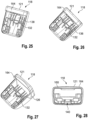
- the first shell part 118 of a belt buckle 100 is shown according to a further embodiment, which is only designed in two parts. Components that are the same or have the same effect are therefore provided with the reference numbers already introduced.
- the housing 112 which is only partially shown, is therefore formed in this embodiment by the two shell parts 118, 120, of which only the first shell part 118 is shown.
- the first shell part 118 has a housing section 164, which essentially corresponds to the front panel 122 in the first embodiment according to the Figures 15 to 21 corresponds.
- the housing section 164 has the circumferential edge 121 and the light guide 126, which is embedded in the first shell part 118 in the previous embodiment.
- the decoupling surface 160 of the light guide 126 is provided on the edge 121, analogous to the first embodiment, which is now arranged on the first shell part 118.
- the first shell part 118 according to the previous embodiment therefore, in comparison to the first shell part 118 according to this embodiment, additionally has the front panel 122, which in this embodiment is formed in one piece with the first shell part 118 and is referred to as the housing section 162.
- the lamp is 132, which is in the Figures 25 to 27 is shown, also arranged on the inner surface of the first shell part 118. Accordingly, in this embodiment, both the lamp 132 and the light guide 126 are provided on the same housing section or part of the housing 12. This also applies to the coupling element 138, which interacts with the lamp 132 via its coupling surface 140.
- the first shell part 118 since it has the light guide 126, has preferably been manufactured in a multi-component injection molding process.
- the light guide 126 is therefore essentially completely surrounded by the housing material of the first shell part 118 or essentially embedded in the first shell part 118.
- the second shell part 120 in this embodiment can be designed analogously to the second shell part 120 according to the previous embodiment and can be manufactured in a one-component injection molding process, since it can be a standardized component.
- the second shell part 120 is placed or pushed on and fixed with the first shell part 118, so that the complete belt buckle housing 112 is trained.
- the parts forming the housing 112 i.e. the two shell parts 118, 120 and possibly the front panel 122, are placed on one another or pushed on or inserted in order to provide an easily detachable housing 112. This means that the lamp 26 can be replaced quickly and easily if necessary.
- the components for the belt buckle mechanism which interact with the tongue, are generally inserted into the first shell part 118 before the belt buckle 100 is assembled.
- the geometry of the light guide 126 and the optional insertion of lenses ensure that the decoupling surface 160 is homogeneously illuminated, so that a uniformly circumferential band of light marks the recording area 114, whereby it can be easily found by the vehicle occupant.
- a chrome element is provided on the edge 121 in order to make the appearance of the belt buckle housing 112 appear more high-quality.
- the chrome element can be designed as a circumferential chrome ring and in particular can be arranged adjacent to the coupling-out surface 160 in such a way that the coupled-out light is reflected on the chrome surface.
- the chrome element is preferably provided next to the coupling-out surface 160 on the side of the coupling-out surface 160 facing away from the insertion opening 114.
- the light source 132 can generally be designed as a type of pre-assembly unit, which means that electrical connections and optionally a series resistor are provided, which only need to be contacted when installing the belt buckle 100.
Landscapes
- Engineering & Computer Science (AREA)
- General Engineering & Computer Science (AREA)
- Microelectronics & Electronic Packaging (AREA)
- Buckles (AREA)
- Automotive Seat Belt Assembly (AREA)
Description
- Die Erfindung betrifft ein Gurtschloss eines Sicherheitsgurts.
- Ein Gurtschloss ist Teil einer Sicherheitseinrichtung bei einem Fahrzeug und ist fest mit der Karosserie des Fahrzeugs verbunden. In das Gurtschloss kann eine Steckzunge eingesteckt werden, an der ein Gurtband vorgesehen ist, das bei eingesteckter Steckzunge einen Fahrzeuginsassen teilweise umgibt, um diesen bei einer starken Verzögerung des Fahrzeugs am Fahrzeugsitz zu fixieren.
- Gurtschlösser mit Beleuchtungseinrichtungen sind allgemein aus dem Stand der Technik bekannt, wobei die Beleuchtung zur Kennzeichnung eines Aufnahmebereichs für eine Steckzunge dient, sodass der Fahrzeuginsasse das Gurtschloss schneller auffinden kann. Das schnelle Auffinden des Gurtschlosses erhöht die Anschnallquote, da der Fahrzeuginsasse nicht nach dem Gurtschloss suchen muss, wodurch die Motivation zum Anschnallen sinken kann. Die Beleuchtungsvorrichtungen sollen eine zuverlässige und dauerhafte Beleuchtung des Aufnahmebereichs sicherstellen.
- Die aus dem Stand der Technik bekannten Gurtschlösser weisen meist ein Gurtschlossgehäuse auf, das in der Regel durch ein Schweißverfahren hergestellt worden ist, indem zwei Gehäusehälften stoffschlüssig miteinander verbunden worden sind. Aufgrund dieser stoffschlüssigen Verbindung kann die Beleuchtungseinrichtung nur mit erheblichem Aufwand ausgewechselt werden, was als nachteilig empfunden wird. Desweiteren ist der Bauraum innerhalb des Gurtschlosses begrenzt, weswegen eine sehr kompakte Bauweise der Beleuchtungseinrichtung nötig ist. Darüber hinaus soll der Aufnahmebereich großflächig und mit hoher Lichtintensität beleuchtet werden, sodass der Fahrzeuginsasse den Aufnahmebereich auch bei ungünstigen Stellungen des Gurtschlosses auffinden kann. Bisherige Gurtschlösser erfüllen diese Vorgaben nicht zur vollsten Zufriedenheit. Ein Gurtschloss gemäß dem Oberbegriff von Anspruch 1 ist aus dem Dokument
US 2012/089302 A1 bekannt. - Aufgabe der Erfindung ist es, ein Gurtschloss bereitzustellen, das eine möglichst gute und dauerhafte Ausleuchtung des Aufnahmebereichs der Steckzunge bei minimalem Platzbedarf ermöglicht und einet beleuchtete Steckzungen-Einstecköffnung bereitstellt. Außerdem ist Aufgabe der Erfindung, ein Gurtschloss bereitzustellen, das einfach und kostengünstig zu fertigen ist und zudem individuelle Anpassungen des Gurtschlosses zum Beispiel entsprechend den Kundenwünschen für verschiedene Fahrzeugtypen zulässt.
- Erfindungsgemäß wird dies mit einem Gurtschloss mit einem Gehäuse und einer im Bereich einer Steckzungen-Einstecköffnung vorhandenen Beleuchtungseinrichtung erreicht, wobei die Beleuchtungseinrichtung ein Leuchtmittel und einen Lichtleiter mit einem Lichtaustrittsbereich umfasst und der Lichtleiter einen ringförmigen Abschnitt aufweist, der die Steckzungen-Einstecköffnung zumindest großteils umgibt. Das Vorsehen eines ringförmigen Abschnitts am Lichtleiter erlaubt es, die Steckzungen-Einstecköffnung gezielt an beliebigen Stellen entlang ihres Umfangs und vorzugsweise über ihren gesamten Umfang zu beleuchten und so eine eindeutige, wertig wirkende Kennzeichnung der Steckzungen-Einstecköffnung zu bewirken. Die Beleuchtung erfolgt in einem Bereich, der zum einen vom Fahrzeuginsassen beim Einstecken der Steckzunge gut wahrnehmbar ist und der zum anderen so positioniert ist, dass die Verwendung beliebiger Designelemente im Bereich des Körpers des Gehäuses möglich ist.
- Das Gehäuse, im folgenden auch als Gurtschlossgehäuse bezeichnet, kann beispielsweise einen umlaufenden Rand aufweisen, der einen Aufnahmebereich für eine Steckzunge umrandet, sowie eine Beleuchtungseinrichtung, die einen Lichtleiter und ein Leuchtmittel aufweist, wobei der Lichtleiter einen Lichtaustrittsbereich in Form einer Auskoppelfläche hat, die am Rand des Gurtschlossgehäuses vorgesehen ist, die den Lichtaustrittsbereich bildet. Der Rand des Gurtschlossgehäuses stellt dabei den Abschnitt des Gurtschlossgehäuses dar, der unmittelbar im Sichtbereich des Fahrzeuginsassen liegt, wenn das Gurtschloss seine typische Position im Fahrzeug einnimmt. Da die Auskoppelfläche des Lichtleiters an diesem Rand vorgesehen ist, ist sichergestellt, dass der Aufnahmebereich, der die Steckzungen-Einstecköffnung bildet, derart gut ausgeleuchtet ist, dass der Fahrzeuginsasse diesen auch bei ungünstigen Stellungen des Gurtschlosses auffinden kann. Über den Lichtleiter wird das vom Leuchtmittel ausgesandte Licht zur Auskoppelfläche geleitet, wodurch eine kompakte Anordnung der Beleuchtungseinrichtung möglich ist. Dies liegt daran, dass das Leuchtmittel selbst an einer Position innerhalb des Gurtschlosses angeordnet werden kann, an der mehr Bauraum zur Verfügung steht als direkt am Rand. Bei dem Leuchtmittel kann es sich insbesondere um eine LED handeln, die besonders kompakt ausgeführt ist.
- Vorzugsweise ist der Lichtaustrittsbereich umfangsmäßig umlaufend an einer axialen Stirnseite des ringförmigen Abschnitts des Lichtleiters ausgebildet, was eine um die Steckzungen-Einstecköffnung umlaufende Beleuchtung ermöglicht. Der Lichtaustrittsbereich kann beispielsweise etwa 1 mm in Radialrichtung (radial zur Einsteckrichtung) in der Breite betragen, was eine dezente, aber dennoch deutlich wahrnehmende Beleuchtung im Bereich der Steckzungen-Einstecköffnung ergibt, ohne das Volumen des Gurtschlosses zu erhöhen.
- Vorzugsweise besteht der Lichtleiter aus einem transparenten Kunststoff, insbesondere einem Polycarbonat (PC).
- Um eine gleichmäßige Ausleuchtung zu erreichen, kann der Lichtleiter an einer vom Lichtaustrittsbereich abgewandten Außenfläche eine strukturierte Oberfläche aufweisen. Diese strukturierte Oberfläche ist dann so gestaltet, dass sie nicht plan verläuft, sondern eine Vielzahl von nebeneinander angeordneten, kleinen Strukturen aufweist, die so ausgebildet und ausgerichtet sind, dass sie das Licht in das Innere des ringförmigen Bereichs des Lichtleiters zurückreflektieren und so eine homogene Verteilung des Lichts innerhalb des Lichtleiters bewirken. Vorzugsweise ist die strukturierte Oberfläche an einer dem Lichtaustrittsbereich gegenüberliegenden Stirnseite des ringförmigen Abschnitts des Lichtleiters vorgesehen.
- Die strukturierte Oberfläche weist beispielsweise eine Vielzahl von nebeneinander angeordneten Prismen auf, die insbesondere jeweils einen trapezförmigen oder dreieckigen Querschnitt haben und eine Art Sägezahnstruktur entlang der rückseitigen Stirnseite des Lichtleiters bilden. Auf diese Weise lässt sich auch bei einer punktuellen Einkopplung des Lichts in den Lichtleiter eine sehr gleichmäßige Ausleuchtung des gesamten ringförmigen Abschnitts erreichen.
- Zur Einkopplung des Lichts vom Leuchtmittel in den Lichtleiter kann der Lichtleiter einen axial vom ringförmigen Abschnitt des Lichtleiters abstehenden Fortsatz oder ein Einkoppelelement aufweisen. Der Fortsatz erstreckt sich vorzugsweise bis zu einem Bereich, in dem das Leuchtmittel der Beleuchtungseinrichtung einfach zu platzieren ist und leitet das Licht vom Leuchtmittel zum ringförmigen Abschnitt und zum Lichtaustrittsbereich.
- Um die Verteilung des Lichts im ringförmigen Abschnitt des Lichtleiters weiter zu verbessern, kann beispielsweise im Bereich des Übergangs des Fortsatzes in den ringförmigen Abschnitt im Lichtleiter im ringförmigen Abschnitt eine Ausnehmung vorgesehen sein. Diese Ausnehmung ist dabei so geformt, dass das eingekoppelte Licht gleichmäßig im ringförmigen Abschnitt verteilt wird. Das eingekoppelte Licht wird insbesondere an schräg zur Axialrichtung liegenden Rändern der Ausnehmung in den ringförmigen Abschnitt in Umfangsrichtung hineinreflektiert und so gleichmäßig im ringförmigen Abschnitt verteilt. Beispielsweise ist die Ausnehmung ein Durchbruch im ringförmigen Abschnitt, der etwa eine dreieckige Form aufweist, wobei die Spitze zum Fortsatz gerichtet ist. Anstelle einer dreieckigen Form sind auch andere Formen einsetzbar, die geeigneterweise Reflektionsflächen aufweisen, die schräg zur Axialrichtung verlaufen und so eine Reflektion in den ringförmigen Abschnitt hinein bewirken können.
- Gemäß der Erfindung ist der ringförmige Abschnitt des Lichtleiters radial innerhalb einer zumindest weitgehend umfangsmäßig geschlossenen Frontblende des Gehäuses angeordnet, die als ein weiteres Gehäuseteil anzusehen ist, wobei die Frontblende die Einstecköffnung umrahmt. Die Frontblende schirmt den Lichtleiter radial nach außen ab, wobei sie sich über die gesamte axiale Länge des Lichtleiters und darüber hinaus erstrecken kann. Die Außenoberfläche der Frontblende ist beliebig gestaltbar und kann als kundenspezifisches Designelement eingesetzt werden.
- Eine noch gleichmäßigere Lichtverteilung entlang des Lichtaustrittsbereichs sowie die Möglichkeit einer individuellen Gestaltung des Lichtaustrittsbereichs des Gurtschlosses für unterschiedliche Fahrzeugtypen wird erfindungsgemäss erreicht indem die Frontblende einen ringförmigen, zumindest teiltransparenten Diffusor aufweist, der vorderseitig axial an den Lichtaustrittsbereich des Lichtleiters angrenzt. Dieser Diffusor kann zudem Bereiche des Lichtaustrittsbereichs abdunkeln oder kann die Farbgebung des austretenden Lichts verändern.
- Zwischen Diffusor und Lichtleiter ist zur Reduzierung von Totalreflektionen und aus Gründen eines hohen Lichtaustritts durch den Diffusor ein Luftspalt angeordnet. Die Höhe des Luftspaltes zwischen Diffusor und Lichtleiter beträgt weniger als 0,5 mm, sie liegt vorzugsweise im Bereich von 0,15mm bis 0,35 mm.
- Die dem Lichtleiter abgewandte Außenseite des Diffusors weist eine sehr feinkörnig ausgebildete Struktur auf, durch die die Homogenität des Lichtaustritts noch einmal verbessert wird. Dazu ist der Diffusor mit einer sehr geringen Körnigkeit aufgeraut.
- Mit Ausnahme des Diffusors ist die Frontblende bevorzugt opak ausgebildet, sodass Licht nur durch den Diffusor austritt.
- Frontblende und Diffusor lassen sich einstückig im Zweikomponenten-Spritzgussverfahren herstellen, beispielsweise aus Acrylnitril-Butadien-Styrol (ABS) und Polycarbonat (PC).
- Frontblende und Lichtleiter sind jedoch vorzugsweise getrennte Bauteile, wobei aber auch eine einstückige Fertigung denkbar wäre. Die Frontblende kann bei der Fertigung des Gurtschlosses auf den Lichtleiter aufgesteckt werden, und Lichtleiter und Frontblende können zur endgültigen Befestigung miteinander verschweißt werden, beispielsweise durch Ultraschall- oder Laserschweißen.
- Das Gehäuse des Gurtschlosses weist vorzugsweise ein erstes Schalenteil auf, das einen ringförmig umlaufenden Vorsprung hat, der radial innerhalb des Lichtleiters angeordnet ist. Dieser umlaufende Vorsprung ist an einem einstecköffnungsseitigen Ende des ersten Schalenteils angeordnet, und der ringförmige Abschnitt des Lichtleiters ist so ausgebildet, dass er auf den Vorsprung des ersten Schalenteils aufgesteckt werden kann. Der ringförmig umlaufende Vorsprung des ersten Schalenteils schirmt den Lichtleiter radial nach innen zur Steckzungen-Einstecköffnung ab, sodass dort kein unerwünschtes Licht austritt.
- Der Lichtleiter kann mit dem ringförmig umlaufenden Vorsprung des ersten Schalenteils verschweißt oder auf eine andere geeignete Art an diesem befestigt sein.
- Die Beleuchtungseinrichtung umfasst vorzugsweise ein elektronisches Steuermodul, in dem das Leuchtmittel sowie eine Elektronik angeordnet sind. Insbesondere ist das elektronische Steuermodul an der Innenseite des ersten Schalenteils des Gehäuses befestigt. Als Leuchtmittel werden z.B. eine oder mehrere LEDs eingesetzt. Eine Möglichkeit zum Farbwechsel des Leuchtmittels ist damit einfach vorzusehen. Die Farbwahl lässt sich in einem Speicher des elektronischen Steuermoduls ablegen und so für verschiedene Fahrzeugtypen anpassen.
- Die elektrische Zuleitung kann in eine elektrische Zuleitung eines Sitzbelegungs-Erkennüngsschalters im Gurtschloss integriert sein, um die Zahl der separaten elektrischen Kabel zu verringern. Eine übermäßige Belastung der Zuleitung lässt sich durch eine Zugentlastung am ersten Schalenteil des Gehäuses verhindern
- Es ist möglich, das elektronische Steuermodul am ersten Schalenteil vorzumontieren, was in der Endmontage die Zahl der einzelnen Komponenten des Gurtschlosses reduziert. Selbstverständlich kann das elektronische Steuermodul auch an einem anderen Gehäuseteil platziert werden.
- Das elektrische Steuermodul ist vorzugsweise als LIN-Modul ausgebildet (Local Interconnect Network Bus) und ist mit einer allgemeinen Fahrzeugelektronik verbindbar.
- In einer bevorzugten Ausführungsform besteht das Gehäuse des Gurtschlosses lediglich aus dem ersten Schalenteil, der Frontblende und einem zweiten Schalenteil, sodass eine schnelle und unkomplizierte Montage des Gurtschlosses möglich ist.
- Gemäß einem Aspekt ist der Lichtleiter mit dem Gurtschlossgehäuse verbunden, insbesondere verrastet oder unlösbar daran angebracht. Hierdurch ist eine besonders kompakte Ausbildung des Gurtschlossgehäuses möglich, da der Lichtleiter nicht mittels Befestigungsmitteln am Gurtschlossgehäuse befestigt werden muss. Dies vereinfacht zudem die Herstellung des Gurtschlosses. Durch eine Rastverbindung ist ferner ein Wechseln des Lichtleiters möglich. Der Lichtleiter kann insbesondere in einem 2-Komponenten-Spritzgießverfahren mit dem zugehörigen Gehäuseteil spritzgegossen werden, sodass keine Montage nötig ist. Der Lichtleiter kann demnach am Gurtschlossgehäuse angespritzt sein.
- Ferner kann die Auskoppelfläche umlaufend ausgebildet sein. Die am Rand vorgesehene Auskoppelfläche kann demnach die den Aufnahmebereich bildende Einstecköffnung ringförmig umschließen, sodass der Fahrzeuginsasse schnell erkennen kann, wo sich der Aufnahmebereich befindet, nämlich in dem von der Auskoppelfläche eingeschlossenen Bereich. Hierdurch erhöht sich die Anschnallquote, da der Fahrzeuginsasse nicht lange nach dem Aufnahmebereich suchen muss.
- Ein weiterer Aspekt sieht vor, dass der Lichtleiter ein Einkoppelelement aufweist, das mit dem Leuchtmittel gekoppelt und insbesondere keilförmig zulaufend ausgebildet ist. Über das Einkoppelelement des Lichtleiters ist sichergestellt, dass das vom Leuchtmittel ausgesandte Licht vollständig in den Lichtleiter eingekoppelt wird. Hierdurch erhöht sich die Leuchtstärke im Bereich der Auskoppelfläche. Aufgrund der Keilförmigkeit des Einkoppelelements ist dennoch ein platzsparender Lichtleiter geschaffen, der nur im Einkoppelbereich einen entsprechend großen Querschnitt aufweist.
- Insbesondere ist das Gurtschlossgehäuse mehrteilig aus mehreren Schalenteilen zusammengesetzt, wobei der Lichtleiter einem Gehäuseabschnitt zugeordnet ist, an dem der Rand ausgebildet ist. Durch die mehrteilige Ausbildung des Gurtschlossgehäuses ist ein schnelles und einfaches Öffnen des Gurtschlossgehäuses möglich, wodurch die Beleuchtungseinrichtung schnell und einfach gewechselt werden kann. Ferner ist sichergestellt, dass die Auskoppelfläche am Rand des Gurtschlossgehäuses vorgesehen ist, da der Lichtleiter an dem Gehäuseabschnitt des mehrteiligen Gurtschlossgehäuses angeordnet ist.
- Ein weiterer Aspekt sieht vor, dass der Lichtleiter im Wesentlichen im Gehäuseabschnitt eingebettet ist. Dies bedeutet, dass der Lichtleiter im Wesentlichen von Gehäusematerial umgeben ist, wodurch keine zusätzlichen Lichtauskoppelflächen entstehen, wie dies der Fall wäre, wenn der Lichtleiter nur an der Innenseite des Gurtschlossgehäuses angeordnet wäre. Der Lichtleiter ist demnach im Wesentlichen vom Gehäuseabschnitt komplett umschlossen. Lediglich der Auskoppel- und der Einkoppelbereich sind dabei nicht vom Gehäusematerial des Gehäuseabschnitts umschlossen, in dem der Lichtleiter eingebettet ist.
- Insbesondere kann das Gurtschlossgehäuse zweiteilig ausgebildet sein und zwei Schalenteile oder Gehäuseschalen umfassen, wobei der Gehäuseabschnitt an einer ersten Gehäuseschale vorgesehen ist. Über die zweiteilige Ausbildung ist ein schnelles und einfaches Öffnen des Gurtschlossgehäuses möglich sowie eine einfache Herstellung, da eine erste Gehäuseschale die wesentlichen Teile des Gurtschlosses aufweist, beispielsweise die Beleuchtungsvorrichtung, wohingegen die zweite Gehäuseschale lediglich zum Schließen des Gurtschlossgehäuses dient. Die zweite Gehäuseschale stellt demnach eine Art Deckelelement dar. Bei der zweiten Gehäuseschale kann es sich um eine standardisierte Gehäuseschale handeln.
- Alternativ kann das Gurtschlossgehäuse dreiteilig ausgebildet sein und zwei Schalenteile sowie ein, insbesondere einsteckbares, Gehäuseteil, entsprechend der oben beschriebenen Frontblende umfassen, an dem der Gehäuseabschnitt vorgesehen ist. Bei den beiden Schalenteilen kann es sich um herkömmliche, standardisierte Gurtschlossschalen handeln, die miteinander gekoppelt werden können, um eine Art Grundkörper des Gehäuseschlosses zu bilden. Das Gehäuseteil, welches in den Grundkörper einsetzbar oder einsteckbar ist, weist den Gehäuseabschnitt auf, an dem der Lichtleiter vorgesehen ist. Das Gehäuseteil ist daher ringförmig ausgebildet und stellt den Rand des Gurtschlossgehäuses bereit, der den Aufnahmebereich für die Steckzunge umrandet.
- Insbesondere kann der Lichtleiter eine Verbindungsstruktur aufweisen, mit der das die Frontblende bildende Gehäuseteil mit den anderen Schalenteilen verbindbar ist. Über den Lichtleiter wird das Gehäuseteil mit den beiden Schalenteilen fest gekoppelt, wodurch ein vollständiges Gurtschlossgehäuse bereitgestellt ist.
- Ein oben beschriebenes Gurtschloss kann so hergestellt werden, dass der Lichtleiter und wenigstens ein Gehäuseabschnitt gleichzeitig spritzgegossen werden, insbesondere in einem Mehrkomponentenspritzgießverfahren. Hierdurch ist eine besonders schnelle und einfache Herstellung des Gurtschlosses möglich, da das Gurtschlossgehäuse zumindest teilweise direkt mit dem Lichtleiter ausgebildet wird. Der Lichtleiter muss daher nicht mehr nachträglich mit dem Gurtschlossgehäuse gekoppelt werden. Ferner ist hierüber sichergestellt, dass die Orientierung des Lichtleiters innerhalb des Gurtschlossgehäuses korrekt ist, wodurch eine homogene Beleuchtung der Auskoppelfläche garantiert ist. Die übrigen Teile des Gurtschlosses können als einfaches und kostengünstiges Spritzgießteil ausgebildet sein, das lediglich eine Materialkomponente aufweist.
- Insbesondere werden der Lichtleiter und der wenigstens eine Gehäuseabschnitt derart spritzgegossen, dass der Lichtleiter im Wesentlichen im Gehäuseabschnitt eingebettet ist. Der Lichtleiter ist dadurch einerseits von dem ihn umgebenen Gehäusematerial geschützt, und andererseits ist sichergestellt, dass der Lichtleiter lediglich die am Rand vorgesehene Auskoppelfläche aufweist. Hierdurch ist die Lichtintensität an der Auskoppelfläche entsprechend hoch, da keine Streuverluste oder ähnliches auftreten.
- Die Erfindung wird nachfolgend anhand eines Ausführungsbeispiels und mit Bezug auf die beigefügten Zeichnungen näher beschrieben. In den Zeichnungen zeigen:
-
Figur 1 eine schematische perspektivische Darstellung eines erfindungsgemäßen Gurtschlosses; -
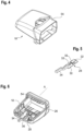
Figur 2 das Gurtschloss ausFigur 1 in einer Seitenansicht; -
Figur 3 das Gurtschloss ausFigur 1 in einer Draufsicht; -
Figur 4 ein erstes Schalenteil des Gehäuses des Gurtschlosses ausFigur 1 ; -
Figur 5 ein elektronisches Steuermodul der Beleuchtungseinrichtung des Gurtschlosses ausFigur 1 ; -
Figur 6 eine Darstellung des elektronischen Steuermoduls, montiert im ersten Schalenteil; -
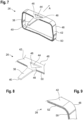
Figur 7 eine perspektivische Darstellung eines Lichtleiters des erfindungsgemäßen Gurtschlosses ausFigur 1 ; -
Figuren 8 und 9 Details des Lichtleiters ausFigur 7 ; -
Figur 10 eine Variante des Lichtleiters ausFigur 7 ; -
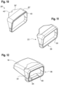
Figur 11 eine Frontblende des Gurtschlosses ausFigur 1 , -
Figur 12 ein erstes Schalenteil mit montiertem Lichtleiter und montierter Frontblende für das Gurtschloss ausFigur 1 ; -
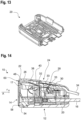
Figur 13 die Innenseite eines zweiten Schalenteils des Gehäuses des Gurtschlosses ausFigur 1 ; -
Figur 14 eine schematische Schnittansicht des erfindungsgemäßen Gurtschlosses ausFigur 1 ; -
Figur 15 eine Perspektivansicht eines erfindungsgemäßen Gurtschlosses gemäß einer weiteren Ausführungsform, -
Figur 16 eine weitere Perspektivansicht des Gurtschlosses ausFigur 1 , -
Figur 17 eine Perspektivansicht eines Gehäuseteils des Gurtschlosses aus denFiguren 15 und 16 , -
Figur 18 eine weitere Perspektivansicht des Gehäuseteils ausFigur 17 , -
Figur 19 eine weitere Perspektivansicht des Gehäuseteils ausFigur 17 , -
Figur 20 eine weitere Perspektivansicht des Gehäuseteils ausFigur 17 , -
Figur 21 eine weitere Perspektivansicht des Gehäuseteils ausFigur 17 , -
Figur 22 eine Perspektivansicht einer Gehäuseschale eines Gurtschlosses gemäß einer weiteren Ausführungsform, -
Figur 23 eine weitere Perspektivansicht der Gehäuseschale ausFigur 22 , -
Figur 24 eine weitere Perspektivansicht der Gehäuseschale ausFigur 22 , -
Figur 25 eine weitere Perspektivansicht der Gehäuseschale ausFigur 22 , -
Figur 26 eine weitere Perspektivansicht der Gehäuseschale ausFigur 22 , -
Figur 27 eine halbtransparente Perspektivdarstellung der Gehäuseschale derFiguren 22 bis 26 , und -
Figur 28 eine Draufsicht auf die Gehäuseschale derFiguren 22 bis 27 . -
Figur 1 zeigt ein Gurtschloss 10 mit einem Gehäuse 12, in dem eine Steckzungen-Einstecköffnung 14 für eine nicht näher dargestellte Steckzunge eines Sicherheitsgurtsystems in einem Fahrzeug vorgesehen ist. Das Gehäuse 12 umschließt einen Träger 16, an dem eine innere Mechanik zur Fixierung der Steckzunge inklusive einer Taste 17 zum Lösen der Steckzunge montiert ist (siehe auchFigur 14 ). Der Träger 16 weist einen Abschnitt auf, der sich aus dem Gehäuse 12 in Axialrichtung A hinaus erstreckt und der zur Befestigung des Gurtschlosses 10 am Fahrzeug dient. - Das Gehäuse 12 besteht in der hier gezeigten Ausführungsform aus mehreren Gehäuseteilen, nämlich einem ersten Schalenteil 18 (siehe auch
Figuren 4 und 6 ) einem gegenüberliegenden zweiten Schalenteil 20 (siehe auchFigur 13 ) sowie einer Frontblende 22 (näher dargestellt in denFiguren 11 und 12 ), die axial an beide Schalenteile 18 angrenzt. - Außerdem weist das Gurtschloss 10 eine Beleuchtungseinrichtung 24 auf (siehe
Figur 14 ), die einen Lichtleiter 26 (siehe im DetailFiguren 7 bis 10 ) sowie ein elektronisches Steuermodul 28 (siehe insbesondereFiguren 5 und 6 ) umfasst. - Das elektronische Steuermodul 28 der Beleuchtungseinrichtung 24 hat eine Steuerplatine 30, auf der ein oder mehrere LEDs als Leuchtmittel 32 sowie eine entsprechende Elektronik 33 vorgesehen sind, die die Leuchtmittel 32 in Leuchtdauer, Leuchtintensität und gegebenenfalls Leuchtfarbe ansteuern kann. Die Leuchtmittel 32 können wahlweise in nur einer Farbe vorgesehen sein, oder es können mehrere Leuchtmittel 32 in unterschiedlichen Farben vorhanden sein, die von der Elektronik 33 so angesteuert werden, dass eine beliebige Farbe erzeugt wird. Die Farbwahl kann situationsabhängig gestaltet werden, auch Farbwechsel sind möglich.
- Das elektronische Steuermodul 28 ist beispielsweise als LIN-Modul zur Verbindung mit einem LIN-Bus im Fahrzeug ausgebildet.
- Eine elektrische Zuleitung 34 ermöglicht die Versorgung des elektronischen Steuermoduls 28 mit elektrischer Energie. Die elektrische Zuleitung 34 ist beispielsweise mit einer Versorgungsleitung für einen (nicht näher dargestellten) Schalter zur Erfassung der eingesteckten Steckzunge zusammengelegt.
- Das elektronische Steuermodul 28 ist in diesem Beispiel an der Innenseite des ersten Schalenteils 18 fixiert, beispielsweise durch eine Rast- oder Schweißverbindung. Eine Kabelführung 36 ist in die Innenseite des ersten Schalenteils 18 integriert (siehe
Figur 6 ) und bewirkt hier auch eine Zugentlastung für die Zuleitung 34. - Das Licht aus den Leuchtmitteln 32 wird in den Lichtleiter 26 eingekoppelt. Der Lichtleiter 26 weist hierzu einen in Axialrichtung A von der Einstecköffnung 14 weg verlaufenden Fortsatz 38 auf, der als Einkoppelelement dient und der an einem freien Ende eine stirnseitige Einkoppelfläche 40 aufweist, in die das von den Leuchtmitteln 32 abgestrahlte Licht eintritt.
- An seinem anderen Ende geht der Fortsatz 38 in einen ringförmigen Abschnitt 42 über, der hier umfangsmäßig geschlossen ist.
- Im Bereich des Übergangs ist eine als Öffnung im ringförmigen Abschnitt 42 ausgebildete Ausnehmung 44 vorgesehen, hier in Form eines Dreiecks, dessen Spitze zur Einkoppelfläche 40 weist. Die schräg zur Axialrichtung A gerichteten Seiten 46 der Ausnehmung 44 dienen dazu, das durch den Fortsatz 38 in den ringförmigen Abschnitt 42 eintretende Licht in Umfangsrichtung in den ringförmigen Abschnitt 42 hinein zu reflektieren.
- Die dem Fortsatz 38 abgewandte Stirnseite 48 des ringförmigen Abschnitts 42 des Lichtleiters 26 bildet einen Lichtaustrittsbereich 60. In diesem Beispiel ist die Stirnseite 48 eben gestaltet.
- Die der Stirnseite 48 gegenüberliegende Stirnseite 50 des ringförmigen Abschnitts 42 weist hier dagegen eine strukturierte Oberfläche auf. In diesem Beispiel sind eine Vielzahl von gleichförmigen Strukturen 52 nebeneinander platziert, wobei in diesem Fall sind die Strukturen 52 durch Prismen gebildet sind, die jeweils einen trapezförmigen Querschnitt haben und deren Längsrichtung quer zur Umfangsrichtung ausgerichtet ist. Dies ist in den
Figuren 8 und 9 angedeutet. - Die Strukturen 52 dienen dazu, das Licht im ringförmigen Abschnitt 42 in Richtung zur vorderen Stirnseite 48 zu reflektieren, wo es den Lichtleiter 26 verlassen soll.
-
Figur 10 zeigt eine Variante eines Lichtleiters 26'. Hier ist der Fortsatz 38' kürzer ausgebildet, dafür die Einkoppelfläche 40' breiter, sodass beispielsweise das Leuchtmittel 32 einfacher mehrere nebeneinanderliegende LEDs aufweisen kann. Es können auch mehrere Einkoppelflächen 40' nebeneinander liegen oder eine bogenförmig um das Leuchtmittel 32 verlaufende Einkoppelfläche vorhanden sein. Die rückwärtige Stirnseite kann auch hier strukturiert oder glatt ausgebildet sein. - Das erste Schalenteil 18 des Gehäuses 12 hat einen ringförmigen Vorsprung 54 (siehe
Figuren 6 und12 ), der um die Steckzungen-Einstecköffnung 14 herum verläuft. Der Vorsprung 54 ist einstückig mit dem restlichen ersten Schalenteil 18 ausgebildet. Das gesamte erste Schalenteil 18, insbesondere aber der Vorsprung 54, ist in diesem Beispiel lichtundurchlässig, also opak, ausgebildet. Als Material für das erste Schalenteil 18, aber auch die anderen Teile des Gehäuses 12, kommt beispielsweise Acrylnitril-Butadien-Styrol (ABS) oder Polypropylen (PP) infrage. - Der Lichtleiter 26, 26' besteht beispielsweise aus Polycarbonat (PC).
- Bei der Montage des Gurtschlosses 10 wird der Lichtleiter 26 mit seinem ringförmigen Abschnitt 42 auf den Vorsprung 54 am ersten Schalenteil 18 aufgesteckt und kann mit dem Vorsprung 54 beispielsweise durch Schweißen (Ultraschall- oder Laserschweißen) oder Kleben verbunden werden.
- Eine Lichtabstrahlung des Lichtleiters 26 radial nach innen wird durch den Vorsprung 54 verhindert. Der Vorsprung 54 erstreckt sich in Axialrichtung A in diesem Beispiel wenigstens bis zur Stirnseite 48 des Lichtleiters 26 oder sogar ein wenig darüber hinaus, wie in
Figur 14 zu erkennen ist. - Die Frontblende 22 des Gehäuses 12 ist hier ebenfalls als umfangsmäßig geschlossen umlaufender Ring ausgebildet (siehe
Figuren 11 und 12 ) und ist auf den Lichtleiter 26 aufgesteckt (Figur 12 undFigur 14 ). Frontblende 22 und Lichtleiter 26 sind außerdem auf geeignete Weise aneinander befestigt, z.B. durch eine Rast-, Kleb- oder Schweißverbindung, beispielsweise über Ultraschall- oder Laserschweißen, und sind fest und nicht lösbar miteinander verbunden. - Die Frontblende 22 ist entlang ihrer Umfangsfläche opak ausgeführt und blockiert somit eine Abstrahlung von Licht aus dem Lichtleiter 26 in Radialrichtung r nach außen. Die Frontblende 22 kann als Designelement gestaltet sein, beispielsweise mit einer verchromten Außenoberfläche oder in Klavierlack-Optik. Die Frontblende 22 wird separat von den anderen Gehäuseteilen gefertigt, sodass die Optik des Gurtschlosses 10 durch Vorsehen einer anders gestalteten Frontblende 22 veränderbar ist.
- An der steckzungenseitigen Stirnseite 56 der Frontblende 22 ist ein transparenter, ringförmig umlaufender, die Steckzungen-Einstecköffnung 14 umgebender Diffusor 58 vorgesehen, durch den das aus der Stirnseite 48 des Lichtleiters 26 austretende Licht nach außen dringt. Der Diffusor 58 schließt in Axialrichtung A an die Stirnseite 48 des Lichtleiters 26 an. Dabei ist zwischen dem Diffusor und der Stirnseite 48 des Lichtleiters 26 ein Luftspalt ausgebildet, der in diesem Ausführungsbeispiel eine Höhe von 0,25mm hat.
- Der Diffusor 58 kann so ausgebildet sein, dass er die Farbe des austretenden Lichts beeinflusst und/oder die Abstrahlcharakteristik der Stirnseite 48 des Lichtleiters 26 verändert. Er sorgt aber auch für einen spaltfreien Abschluss des Gehäuses 12 nach außen und verhindert ein Eindringen von Schmutz in das Gehäuse 12. Diffusor 58 und Frontblende 22 sind daher in diesem Beispiel einstückig in einem Zweikomponenten-Spritzgussverfahren hergestellt. Als Material für den Diffusor wird beispielsweise Polycarbonat (PC) verwendet. Die steckzungenseite Stirnseite des Diffusors ist zur Verbesserung der Homogenität des Lichtaustritts strukturiert, d.h. feinkörnig mit einer geringen Rauigkeit aufgeraut.
- Anstelle des Lichtleiters 26 kann stets auch der in
Figur 10 gezeigte Lichtleiter 26' verbaut werden. - Als letzter Montageschritt wird das zweite Schalenteil 20 mit dem ersten Schalenteil 18 verbunden, beispielsweise durch eine Rast-, Klebe- oder Schweißverbindung.
- In Radialrichtung r beträgt die Breite der Stirnseite 48 beispielsweise etwa 1 mm. Die Breite des Diffusors 58 in Radialrichtung r ist hier in derselben Größenordnung gewählt. Auf diese Weise entsteht ein Lichtaustrittsbereich 60 des Gurtschlosses 10, der um die Steckzungen-Einstecköffnung 14 umfangsmäßig umlaufend ausgebildet ist und der etwa 1 mm in der Breite beträgt.
- Der Vorsprung 54 des ersten Schalenteils 18 sowie die Frontblende 22 verhindern eine Abstrahlung von Licht aus dem Lichtleiter 26 in Radialrichtung r, sodass nur aus dem Lichtaustrittsbereich 60 Licht austritt und der Lichtaustrittsbereich 60 den einzigen beleuchteten Abschnitt des Gurtschlosses 10 bildet.
- Die
Figuren 15 bis 28 zeigen weitere Ausführungsformen. - In den
Figuren 15 und 16 ist ein Gurtschloss 100 gemäß einer weiteren Ausführungsform gezeigt, wobei die Schließmechanik des Gurtschlosses 100, die mit einer Steckzunge zusammenwirkt, aus Gründen der Übersichtlichkeit nicht dargestellt ist. - Das Gurtschloss 100 weist ein Gurtschlossgehäuse 112 auf, welches in der gezeigten Ausführungsform dreiteilig ausgebildet ist.
- Das Gehäuse 112 weist ein erstes Schalenteil 118 auf, auch als erste Gehäuseschale ansehbar, ein zweites Schalenteil 120, auch als zweite Gehäuseschale zu bezeichnen, sowie ein Gehäuseteil, das eine Frontblende 122 bildet und das einen Rand 121 hat, der einen Aufnahmebereich 114 für eine Steckzunge mit einer Einstecköffnung für die Steckzunge umrandet.
- Die beiden Schalenteile 118, 120 bilden zusammen einen Grundkörper 123 des Gehäuses 112, in den die Frontblende 122 eingesetzt ist. Dadurch sind die beiden Schalenteile 118, 120 und die Frontblende 122 miteinander gekoppelt, sodass sie das vollständige Gehäuse 112 ausbilden.
- Ferner weist das Gurtschloss 100 eine Beleuchtungseinrichtung 124 auf, die ein Leuchtmittel 132 sowie einen Lichtleiter 126 umfasst. Bei dem Leuchtmittel 132 kann es sich um eine LED handeln, die beispielsweise rotes Licht aussendet. Alternativ kann auch eine mehrfarbige LED vorgesehen sein, sodass die Farbe des ausgesandten Lichts an die Vorlieben des Fahrzeuginsassen anpassbar ist.
- Das Leuchtmittel 132 ist dabei innerhalb des Gurtschlosses 100 vorgesehen, wobei es am ersten Schalenteil 118 angeordnet ist. Der Lichtleiter 126 ist dagegen in einem Gehäuseabschnitt 129 des Gehäuses 112 angeordnet, der in der gezeigten Ausführungsform durch das zweite Schalenteil 120 ausgebildet ist. Daher sind das Leuchtmittel 132 und der Lichtleiter 126 an verschiedenen Teilen des dreiteilig ausgebildeten Gehäuses 12 angeordnet.
- Der Lichtleiter 132 weist ferner ein Einkoppelelement 138 auf, das im zusammengebauten Zustand des Gurtschlosses 100 derart mit dem Leuchtmittel 132 gekoppelt ist, dass das von dem Leuchtmittel 132 ausgehende Licht über das Einkoppelelement 138 in den Lichtleiter 126 eingekoppelt wird.
- Das Einkoppelelement 138 ist keilförmig zulaufend ausgebildet, wodurch das Einkoppelelement 138 eine große Einkoppelfläche 140 aufweist. Das über das Einkoppelelement 138 eingekoppelte Licht verläuft über den Lichtleiter 126 zu einer Auskoppelfläche 160, die am Rand 121 des Gehäuses 112 angeordnet ist.
- In der gezeigten Ausführungsform ist die Auskoppelfläche 160 als umlaufendes Band am Rand 121 ausgebildet, sodass es die Einstecköffnung und den Aufnahmebereich 122 ringförmig umschließt.
- Die Auskoppelfläche 160 weist insbesondere eine Breite von 0,5 mm bis 1,5 mm auf, vorzugsweise 1 mm, und ist direkt an der Oberfläche des Gehäuses 112 angeordnet, die im Sichtbereich des Gurtschlosses 100 ist, wenn dieses eine typische Position in einem Fahrzeug einnimmt.
- In den
Figuren 17 bis 21 ist das der Frontblende 122 der ersten Ausführungsform entsprechende Gehäuseteil separat dargestellt. - Aus den
Figuren 17 bis 21 geht hervor, dass der Lichtleiter 126 zusätzlich zu der Auskoppelfläche 160 und dem Einkoppelelement 138 eine Verbindungsstruktur 162 aufweist, über die die Frontblende 122 mit den beiden Schalenteilen 118, 120 bzw. mit dem Grundkörper 123 gekoppelt werden kann. Die Verbindungsstruktur 162 ist dabei an einem zum Rand 121 entgegengesetzten Ende der Frontblende 122 ausgebildet. - Aus den Figuren geht ferner hervor, dass der Lichtleiter 126 in der Frontblende 122 eingebettet ist, da der Lichtleiter 126 im Wesentlichen vom Gehäusematerial der Frontblende 122 umgeben ist. Lediglich die Auskoppelfläche 160 am Rand 121 sowie das Einkoppelelement 138 und die Verbindungsstruktur 162 sind nicht vom Gehäusematerial umgeben. Die Lichtleitstruktur des Lichtleiters 126 verläuft demnach im Wesentlichen im Inneren der Frontblende 122, sodass vom Lichtleiter 126 nur die Auskoppelfläche 160, das Einkoppelelement 138 sowie die Verbindungsstruktur 162 zu erkennen ist.
- Der Lichtleiter 126 ist demnach in der gezeigten Ausführungsform einstückig mit dem Gehäuseabschnitt 129 bzw. der Frontblende 122 ausgebildet.
- Die Frontblende 122 kann daher vorzugsweise in einem Mehrkomponentenspritzgießverfahren hergestellt werden. Hierdurch ist sichergestellt, dass die innere und die äußere Gehäusefläche der Frontblende 122 aus einem ersten, lichtundurchlässigen Material ausgebildet ist, wohingegen der darin eingebettete Lichtleiter 126 aus einem zweiten, lichtleitenden Material hergestellt ist. Hierdurch ist der Lichtleiter 126 vom Gehäusematerial der Frontblende 122 bzw. der Frontblende 122 umgeben und weist lediglich eine einzige Auskoppelfläche 160 auf.
- Bei dem Material für den Lichtleiter 126 kann es sich beispielsweise um hochtechnologisch veredelte Kunststoffe handeln, die besondere Lichtstreu-, Lichtleiteigenschaften oder einen zusätzlichen Metallic-Effekt aufweisen.
- Dagegen können das erste und das zweite Schalenteil 118, 120 in dieser Ausführungsform in einem Einkomponentenspritzgießverfahren hergestellt worden sein, da es sich bei ihnen um standardisierte Bauteile handeln kann.
- Alternativ kann der Lichtleiter 126 auch als separates Bauteil hergestellt und mit dem Gehäuseabschnitt 129 bzw. der Frontblende 122 verrastet sein. Hierzu können sowohl der Lichtleiter 126 als auch der Gehäuseabschnitt 129 bzw. die Frontblende 122 eine Raststruktur aufweisen.
- In den
Figuren 22 bis 28 ist das erste Schalenteil 118 eines Gurtschlosses 100 gemäß einer weiteren Ausführungsform dargestellt, das lediglich zweiteilig ausgebildet ist. Gleiche oder wirkungsgleiche Bauteile sind daher mit den bereits eingeführten Bezugszeichen versehen. - Das nur teilweise dargestellte Gehäuse 112 ist demnach in dieser Ausführungsform durch die zwei Schalenteile 118, 120 ausgebildet, von denen nur das erste Schalenteil 118 gezeigt ist.
- Das erste Schalenteil 118 weist einen Gehäuseabschnitt 164 auf, der im Wesentlichen der Frontblende 122 bei der ersten Ausführungsform gemäß den
Figuren 15 bis 21 entspricht. Der Gehäuseabschnitt 164 weist analog zur Frontblende 122 aus der ersten Ausführungsform den umlaufenden Rand 121 sowie den Lichtleiter 126 auf, der in der vorherigen Ausführungsform in das erste Schalenteil 118 eingebettet ist. Die Auskoppelfläche 160 des Lichtleiters 126 ist analog zur ersten Ausführungsform am Rand 121 vorgesehen, der nun am ersten Schalenteil 118 angeordnet ist. - Das erste Schalenteil 118 gemäß der vorherigen Ausführungsform weist demnach im Vergleich zum ersten Schalenteil 118 gemäß dieser Ausführungsform zusätzlich die Frontblende 122 auf, die in dieser Ausführungsform einstückig mit dem ersten Schalenteil 118 ausgebildet ist und als der Gehäuseabschnitt 162 bezeichnet wird.
- In dieser Ausführungsform ist das Leuchtmittel 132, welches in den
Figuren 25 bis 27 gezeigt ist, ebenfalls an der Innenfläche des ersten Schalenteils 118 angeordnet. Demnach sind in dieser Ausführungsform sowohl das Leuchtmittel 132 als auch der Lichtleiter 126 an demselben Gehäuseabschnitt bzw. Teil des Gehäuses 12 vorgesehen. Dies trifft auch auf das Einkoppelelement 138 zu, welches über seine Einkoppelfläche 140 mit dem Leuchtmittel 132 zusammenwirkt. - Das erste Schalenteil 118 ist, da es den Lichtleiter 126 aufweist, vorzugsweise in einem Mehrkomponentenspritzgießverfahren hergestellt worden. Der Lichtleiter 126 ist daher vom Gehäusematerial des ersten Schalenteils 118 im Wesentlichen vollständig umgeben bzw. in das erste Schalenteil 118 im Wesentlichen eingebettet.
- Das zweite Schalenteil 120 in dieser Ausführungsform, das in den Figuren nicht dargestellt ist, kann analog zum zweiten Schalenteil 120 gemäß der vorherigen Ausführungsform ausgebildet sein und dabei in einem Einkomponentenspritzgießverfahren hergestellt worden sein, da es sich bei um ein standardisiertes Bauteil handeln kann.
- Bei der zweiteiligen Ausführungsform gemäß den
Figuren 22 bis 28 wird das zweite Schalenteil 120 aufgesetzt oder aufgeschoben und mit dem ersten Schalenteil 118 fixiert, sodass das vollständige Gurtschlossgehäuse 112 ausgebildet ist. - Allgemein ist bei beiden Ausführungsformen des Gurtschlosses 100 vorgesehen, dass die das Gehäuse 112 ausbildenden Teile, also die beiden Schalenteile 118, 120 sowie eventuell die Frontblende 122, aufeinander aufgesetzt oder aufgeschoben bzw. eingesteckt werden, um ein leicht lösbares Gehäuse 112 bereitzustellen. Hierdurch kann das Leuchtmittel 26, sofern dies nötig ist, schnell und einfach ausgewechselt werden.
- In das erste Schalenteil 118 werden generell vor dem Zusammenbau des Gurtschlosses 100 die Bauteile für die Gurtschlossmechanik eingesetzt, die mit der Steckzunge zusammenwirken.
- Generell wird über die Geometrie des Lichtleiters 126 sowie dem optionalen Einsetzen von Linsen sichergestellt, dass die Auskoppelfläche 160 homogen ausgeleuchtet ist, sodass ein gleichmäßig umlaufendes Lichtband den Aufnahmebereich114 markiert, wodurch diese vom Fahrzeuginsassen einfach aufgefunden werden kann.
- Ferner kann generell vorgesehen sein, dass ein Chromelement am Rand 121 vorgesehen ist, um die Optik des Gurtschlossgehäuses 112 hochwertiger erscheinen zu lassen. Das Chromelement kann dabei als umlaufender Chromring ausgebildet sein und insbesondere derart benachbart zur Auskoppelfläche 160 angeordnet sein, dass das ausgekoppelte Licht an der Chromoberfläche reflektiert wird. Das Chromelement ist vorzugsweise neben der Auskoppelfläche 160 auf der von der Einstecköffnung 114 wegweisenden Seite der Auskoppelfläche 160 vorgesehen.
- Das Leuchtmittel 132 kann allgemein als eine Art Vormontageeinheit ausgebildet sein, das heißt, dass elektrische Anschlüsse sowie optional ein Vorwiderstand vorgesehen sind, die beim Einbau des Gurtschlosses 100 nur noch kontaktiert werden müssen.
Claims (17)
- Gurtschloss mit einem Gehäuse (12) und einer im Bereich einer Steckzungen-Einstecköffnung (14) vorhandenen Beleuchtungseinrichtung (24),wobei die Beleuchtungseinrichtung (24) ein Leuchtmittel (32) und einen Lichtleiter (26; 26') mit einem Lichtaustrittsbereich umfasst undder Lichtleiter (26; 26') einen ringförmigen Abschnitt (42; 42') aufweist, der die Steckzungen-Einstecköffnung (14) zumindest großteils umgibt,dadurch gekennzeichnet, dassder ringförmige Abschnitt (42; 42') des Lichtleiters (26; 26') radial innerhalb einer zumindest weitgehend umfangsmäßig geschlossenen Frontblende (22) des Gehäuses (12) angeordnet ist,wobei die Frontblende (22) die Einstecköffnung (14) umrahmt, unddass die Frontblende (22) einen ringförmigen, zumindest teiltransparenten Diffusor (58) aufweist,der axial an den Lichtaustrittsbereich des Lichtleiters (26; 26') angrenzt.
- Gurtschloss nach Anspruch 1, dadurch gekennzeichnet, dass der Lichtaustrittsbereich umfangsmäßig umlaufend an einer axialen Stirnseite (48; 48') des ringförmigen Abschnitts (42; 42') des Lichtleiters (26; 26') ausgebildet ist.
- Gurtschloss nach einem der vorhergehenden Ansprüche, dadurch gekennzeichnet, dass der Lichtleiter (26) an einer vom Lichtaustrittsbereich abgewandten Stirnseite (50) eine strukturierte Oberfläche aufweist.
- Gurtschloss nach Anspruch 3, dadurch gekennzeichnet, dass die strukturierte Oberfläche eine Vielzahl von nebeneinander angeordneten Strukturen (52), insbesondere Prismen, aufweist.
- Gurtschloss nach einem der vorhergehenden Ansprüche, dadurch gekennzeichnet, dass der Lichtleiter (26; 26') einen Fortsatz (38; 38') aufweist, der axial vom ringförmigen Abschnitt (42; 42') des Lichtleiters (26; 26') absteht und über den das Licht des Leuchtmittels (32) in den Lichtleiter (26; 26') eingekoppelt wird.
- Gurtschloss nach Anspruch 5, dadurch gekennzeichnet, dass im Bereich des Übergangs des Fortsatzes (38) in den ringförmigen Abschnitt (42) im ringförmigen Abschnitt (42) eine Ausnehmung (44) vorgesehen ist, die so geformt ist, dass das eingekoppelte Licht gleichmäßig im ringförmigen Abschnitt (42) verteilt wird.
- Gurtschloss nach Anspruch 1, dadurch gekennzeichnet, dass die Frontblende (22) mit Ausnahme des Diffusors (58) opak ausgebildet ist.
- Gurtschloss nach Anspruch 1 oder 7, dadurch gekennzeichnet, dass zwischen dem Diffusor (58) und dem Lichtaustrittsbereich des Lichtleiters (26; 26') ein Luftspalt ausgebildet ist.
- Gurtschloss nach einem der vorhergehenden Ansprüche, dadurch gekennzeichnet, dass das Gehäuse (12) ein erstes Schalenteil (18) aufweist, das einen ringförmig umlaufenden Vorsprung (54) aufweist, der radial einwärts des Lichtleiters (26; 26') angeordnet ist.
- Gurtschloss nach den Ansprüchen 1 und 9, dadurch gekennzeichnet, dass das Gehäuse (12) aus dem ersten Schalenteil (18), der Frontblende (22) und einem zweiten Schalenteil (20) besteht.
- Gurtschloss nach einem der vorhergehenden Ansprüche, dadurch gekennzeichnet, dass die Beleuchtungseinrichtung (24) ein elektronisches Steuermodul (28) umfasst, in dem das Leuchtmittel (32) sowie eine Elektronik (33) angeordnet ist, und insbesondere wobei das elektronische Steuermodul (28) an der Innenseite des ersten Schalenteils (18) des Gehäuses (12) befestigt ist.
- Gurtschloss (100) nach einem der vorhergehenden Ansprüche, dadurch gekennzeichnet, dass der Lichtleiter (126) mit dem Gurtschlossgehäuse (112) verbunden ist, insbesondere verrastet oder unlösbar daran angebracht.
- Gurtschloss (100) nach einem der vorhergehenden Ansprüche, dadurch gekennzeichnet, dass der Lichtleiter (126) ein Einkoppelelement (138) aufweist, das mit dem Leuchtmittel (132) gekoppelt und insbesondere keilförmig zulaufend ausgebildet ist.
- Gurtschloss (100) nach einem der vorhergehenden Ansprüche, dadurch gekennzeichnet, dass das Gurtschlossgehäuse (112) mehrteilig ist, wobei der Lichtaustrittsbereich des Lichtleiters (126) an einem Rand (121) des Gurtschlossgehäuses (112) vorgesehen ist und einem Gehäuseabschnitt (129, 164) zugeordnet ist, an dem der Rand (121) ausgebildet ist.
- Gurtschloss (100) nach Anspruch 14, dadurch gekennzeichnet, dass der Lichtleiter (126) im Wesentlichen im Gehäuseabschnitt (129, 164) eingebettet ist.
- Gurtschloss (100) nach Anspruch 14 oder 15, dadurch gekennzeichnet, dass das Gurtschlossgehäuse (112) zweiteilig ausgebildet ist und zwei Schalenteile (118, 120) umfasst, wobei der Gehäuseabschnitt (164) am ersten Schalenteil (118) vorgesehen ist.
- Gurtschloss (100) nach Anspruch 14 oder 15, dadurch gekennzeichnet, dass das Gurtschlossgehäuse (112) dreiteilig ausgebildet ist und zwei Schaleneteile (118, 120) sowie eine, insbesondere einsteckbare, Frontblende (122) umfasst, an der der Gehäuseabschnitt (129) vorgesehen ist.
Applications Claiming Priority (3)
| Application Number | Priority Date | Filing Date | Title |
|---|---|---|---|
| DE102014010403 | 2014-07-15 | ||
| DE102014016520.5A DE102014016520B4 (de) | 2014-11-10 | 2014-11-10 | Gurtschloss |
| PCT/EP2015/001451 WO2016008585A1 (de) | 2014-07-15 | 2015-07-15 | Gurtschloss |
Publications (3)
| Publication Number | Publication Date |
|---|---|
| EP3169179A1 EP3169179A1 (de) | 2017-05-24 |
| EP3169179B1 EP3169179B1 (de) | 2018-09-19 |
| EP3169179B2 true EP3169179B2 (de) | 2023-12-06 |
Family
ID=53761321
Family Applications (1)
| Application Number | Title | Priority Date | Filing Date |
|---|---|---|---|
| EP15744121.3A Active EP3169179B2 (de) | 2014-07-15 | 2015-07-15 | Gurtschloss |
Country Status (4)
| Country | Link |
|---|---|
| US (1) | US10631597B2 (de) |
| EP (1) | EP3169179B2 (de) |
| CN (1) | CN106572724B (de) |
| WO (1) | WO2016008585A1 (de) |
Families Citing this family (17)
| Publication number | Priority date | Publication date | Assignee | Title |
|---|---|---|---|---|
| DE102015206602A1 (de) | 2014-12-19 | 2016-06-23 | Volkswagen Aktiengesellschaft | Beleuchtetes Gurtschloss |
| DE102015210450A1 (de) * | 2015-06-08 | 2016-12-08 | Autoliv Development Ab | Beleuchtetes Gurtschloss für eine Sicherheitsgurteinrichtung eines Kraftfahrzeuges |
| JP6541182B2 (ja) * | 2015-07-02 | 2019-07-10 | Joyson Safety Systems Japan株式会社 | バックルおよびこれを備えるシートベルト装置 |
| DE102016204961B4 (de) * | 2016-03-24 | 2022-08-11 | Autoliv Development Ab | Beleuchtetes Gurtschloss für eine Sicherheitsgurteinrichtung eines Kraftfahrzeuges |
| DE102016117099A1 (de) * | 2016-09-12 | 2018-03-15 | Autoliv Development Ab | Gurtschloss mit Beleuchtung |
| JP6475305B1 (ja) * | 2017-11-02 | 2019-02-27 | 株式会社東海理化電機製作所 | バックル装置 |
| CN109793318B (zh) * | 2017-11-16 | 2022-10-04 | 天合汽车科技(上海)有限公司 | 用于安全带的发光锁扣 |
| CN108422961B (zh) * | 2018-03-06 | 2023-09-29 | 延锋汽车智能安全系统有限责任公司 | 一种发光插锁 |
| DE102018122239A1 (de) | 2018-09-12 | 2020-03-12 | Trw Automotive Gmbh | Gurtschloss und Verfahren zur Herstellung eines Gurtschlosses |
| DE102019135914A1 (de) * | 2019-12-31 | 2021-07-01 | Zf Automotive Germany Gmbh | Verfahren für ein Sicherheitsgurtsystem, Sicherheitsgurtsystem für ein Fahrzeug und Fahrzeug mit einem Sicherheitsgurtsystem |
| CN114009903B (zh) * | 2021-10-28 | 2023-07-11 | 浙江松原汽车安全系统股份有限公司 | 一种安全带锁扣 |
| USD1034299S1 (en) * | 2021-11-08 | 2024-07-09 | Brogent Technologies Inc. | Illuminated buckle |
| USD1020435S1 (en) * | 2021-11-08 | 2024-04-02 | Brogent Technologies Inc. | Illuminated buckle |
| CN115153162A (zh) * | 2022-07-01 | 2022-10-11 | 浙江松原汽车安全系统股份有限公司 | 一种安全带发光锁扣 |
| DE102023107196B3 (de) * | 2023-03-22 | 2024-09-26 | Autoliv Development Ab | Beleuchtetes Gurtschloss für eine Sicherheitsgurteinrichtung eines Kraftfahrzeuges |
| TWI847646B (zh) * | 2023-04-11 | 2024-07-01 | 宏裕汽車股份有限公司 | 可顯光安全帶扣座 |
| CN121587505A (zh) * | 2024-08-15 | 2026-03-03 | 奥托立夫开发公司 | 安全带锁扣 |
Citations (4)
| Publication number | Priority date | Publication date | Assignee | Title |
|---|---|---|---|---|
| US5892436A (en) † | 1996-11-08 | 1999-04-06 | Trw Inc. | Illuminated seat belt buckle |
| DE69510941T2 (de) † | 1994-12-08 | 1999-11-11 | Valeo Vision, Bobigny | Leuchtring für zigarettenanzünder, insbesondere für kraftfahrzeuge |
| DE102007017394A1 (de) † | 2006-04-07 | 2007-10-18 | TK Holdings, Inc., Auburn Hills | Beleuchtetes Soft-Touch-Schloss für Rückhaltesystem |
| US20100013622A1 (en) † | 2008-07-18 | 2010-01-21 | Tk Holdings Inc. | Adaptive light seatbelt buckle |
Family Cites Families (22)
| Publication number | Priority date | Publication date | Assignee | Title |
|---|---|---|---|---|
| FR1598519A (de) | 1967-12-20 | 1970-07-06 | ||
| GB1201853A (en) | 1968-07-30 | 1970-08-12 | Wingard Ltd | Fastening device for releasably connecting two members |
| SE440307B (sv) | 1977-04-04 | 1985-07-29 | Nsk Warner Kk | Spenne for sekerhetsbelten |
| US4237586A (en) | 1977-10-21 | 1980-12-09 | Nsk-Warner K.K. | Buckle device for safety belt |
| FR2630057B1 (fr) | 1988-04-13 | 1990-07-20 | Neiman Sa | Perfectionnements aux allume-cigares lumineux pour vehicules automobiles |
| JP3103090B2 (ja) * | 1990-05-11 | 2000-10-23 | タカタ株式会社 | シートベルト装置のバックル照明機構 |
| DE9012325U1 (de) | 1990-08-28 | 1990-10-31 | Schoeller & Co Elektrotechnische Fabrik Gmbh & Co, 6000 Frankfurt | Beleuchtungsvorrichtung für das Zündschloß eines Kraftfahrzeugs |
| DE4202120C2 (de) | 1992-01-27 | 1995-04-13 | Schoeller & Co Elektrotech | Elektrischer Zigarrenanzünder, insbesondere für Kraftfahrzeuge |
| DE19528093A1 (de) | 1995-07-31 | 1997-02-13 | Siemens Ag | Diebstahlschutzsystem für ein Kraftfahrzeug |
| AU784343B2 (en) | 2001-03-09 | 2006-03-16 | Robert Bosch Gmbh | Illumination ring |
| DE10119010C2 (de) | 2001-04-18 | 2003-05-28 | Visteon Global Tech Inc | Beleuchtungsanordnung für das Zündschloss eines Kraftfahrzeugs |
| DE202004007872U1 (de) | 2004-05-15 | 2004-09-23 | Juhren, Holger | Sicherheitsgurtschloßbeleuchtung für Pkw |
| JP2007014359A (ja) * | 2005-06-15 | 2007-01-25 | Takata Corp | バックル装置及びシートベルト装置 |
| CN101639200A (zh) | 2008-07-30 | 2010-02-03 | 深圳富泰宏精密工业有限公司 | 导光体及具有该导光体的光源装置 |
| DE102008042472B4 (de) | 2008-09-30 | 2021-04-22 | BSH Hausgeräte GmbH | Leuchtring |
| JP2011125575A (ja) | 2009-12-18 | 2011-06-30 | Inoac Corp | シートベルトバックルの製造方法 |
| US8131144B2 (en) * | 2010-07-09 | 2012-03-06 | Wgi Innovations, Ltd. | Action camera with capability of capturing images in daylight and infrared |
| US20120089302A1 (en) * | 2010-10-06 | 2012-04-12 | Griffin John A | Illuminated seat belt receptacle |
| DE102011114538B4 (de) | 2011-09-29 | 2025-10-23 | Zf Automotive Germany Gmbh | Gurtschlossbaugruppe |
| DE202012012254U1 (de) * | 2012-12-20 | 2013-02-22 | Key Safety Systems, Inc. | Gurtschloss für einen Fahrzeugsicherheitsgurt |
| DE102013003978B4 (de) | 2013-03-08 | 2022-06-09 | Zf Automotive Germany Gmbh | Gurtschloss und Verfahren zum Montieren eines Gurtschlosses |
| EP3031341B1 (de) * | 2014-12-12 | 2018-06-13 | AGM Automotive LLC | Beleuchtetes sicherheitsrückhaltesystem |
-
2015
- 2015-07-15 WO PCT/EP2015/001451 patent/WO2016008585A1/de not_active Ceased
- 2015-07-15 US US15/322,744 patent/US10631597B2/en active Active
- 2015-07-15 CN CN201580038689.XA patent/CN106572724B/zh active Active
- 2015-07-15 EP EP15744121.3A patent/EP3169179B2/de active Active
Patent Citations (4)
| Publication number | Priority date | Publication date | Assignee | Title |
|---|---|---|---|---|
| DE69510941T2 (de) † | 1994-12-08 | 1999-11-11 | Valeo Vision, Bobigny | Leuchtring für zigarettenanzünder, insbesondere für kraftfahrzeuge |
| US5892436A (en) † | 1996-11-08 | 1999-04-06 | Trw Inc. | Illuminated seat belt buckle |
| DE102007017394A1 (de) † | 2006-04-07 | 2007-10-18 | TK Holdings, Inc., Auburn Hills | Beleuchtetes Soft-Touch-Schloss für Rückhaltesystem |
| US20100013622A1 (en) † | 2008-07-18 | 2010-01-21 | Tk Holdings Inc. | Adaptive light seatbelt buckle |
Also Published As
| Publication number | Publication date |
|---|---|
| US20170127765A1 (en) | 2017-05-11 |
| WO2016008585A1 (de) | 2016-01-21 |
| CN106572724A (zh) | 2017-04-19 |
| CN106572724B (zh) | 2020-08-21 |
| EP3169179B1 (de) | 2018-09-19 |
| US10631597B2 (en) | 2020-04-28 |
| EP3169179A1 (de) | 2017-05-24 |
Similar Documents
| Publication | Publication Date | Title |
|---|---|---|
| EP3169179B2 (de) | Gurtschloss | |
| EP3232849B1 (de) | Beleuchtetes gurtschloss | |
| DE102014016520B4 (de) | Gurtschloss | |
| EP2662241B1 (de) | Kraftfahrzeug, umfassend einen Dachhimmel | |
| EP2989273B1 (de) | Vorrichtung mit einer griffschale und mit einer beleuchtungseinrichtung für die griffschale sowie ein verfahren zur montage der vorrichtung | |
| DE102015215254B4 (de) | Beleuchtetes Gurtschloss für eine Sicherheitsgurteinrichtung eines Kraftfahrzeuges | |
| WO2020043532A1 (de) | Beleuchtungsvorrichtung für ein kraftfahrzeug | |
| WO2018149741A1 (de) | Beleuchtungsvorrichtung für ein innenausstattungsteil | |
| DE102016204961A1 (de) | Beleuchtetes Gurtschloss für eine Sicherheitsgurteinrichtung eines Kraftfahrzeuges | |
| DE102014202025A1 (de) | Lampe | |
| DE102017213369A1 (de) | Beleuchtbare Abdeckung für einen Funktionsraum eines Fahrzeugs | |
| DE202008005748U1 (de) | Beleuchtung für das Gurtschloss eines Sicherheitsgurtes | |
| EP3727073B1 (de) | Beleuchtetes gurtschloss für eine sicherheitsgurteinrichtung eines kraftfahrzeuges | |
| DE102010054929A1 (de) | Leuchteinrichtung für ein Fahrzeug mit einem lichtleitenden Optikelement | |
| DE102018205120A1 (de) | Fahrzeuglampe | |
| DE102015210450A1 (de) | Beleuchtetes Gurtschloss für eine Sicherheitsgurteinrichtung eines Kraftfahrzeuges | |
| WO2018041479A1 (de) | Innenraumverkleidung für ein kraftfahrzeug | |
| DE102015011412A1 (de) | Verfahren zum Herstellen eines Bauteils mit einer beleuchtbaren Symbolik für eine Bedieneinrichtung eines Kraftfahrzeugs | |
| DE102012103309A1 (de) | Lichtleitvorrichtung | |
| DE102023114230B3 (de) | Beleuchtetes Gurtschloss für eine Sicherheitsgurteinrichtung eines Kraftfahrzeuges und Verfahren zur Ansteuerung eines beleuchteten Gurtschlosses für eine Sicherheitsgurteinrichtung eines Kraftfahrzeuges | |
| DE102016219277B4 (de) | Innenbeleuchtungsvorrichtung für ein Kraftfahrzeug | |
| DE102024001829A1 (de) | Leuchtemblem für ein Kraftfahrzeug und Kraftfahrzeug | |
| DE102022003970A1 (de) | Beleuchtetes Exterieur Zierelement mit Chromoptik | |
| EP4537733A1 (de) | Beleuchtungseinrichtung | |
| DE102022121127A1 (de) | Airbagmodul mit Lichtaustrittsfläche |
Legal Events
| Date | Code | Title | Description |
|---|---|---|---|
| STAA | Information on the status of an ep patent application or granted ep patent |
Free format text: STATUS: THE INTERNATIONAL PUBLICATION HAS BEEN MADE |
|
| PUAI | Public reference made under article 153(3) epc to a published international application that has entered the european phase |
Free format text: ORIGINAL CODE: 0009012 |
|
| STAA | Information on the status of an ep patent application or granted ep patent |
Free format text: STATUS: REQUEST FOR EXAMINATION WAS MADE |
|
| 17P | Request for examination filed |
Effective date: 20161220 |
|
| AK | Designated contracting states |
Kind code of ref document: A1 Designated state(s): AL AT BE BG CH CY CZ DE DK EE ES FI FR GB GR HR HU IE IS IT LI LT LU LV MC MK MT NL NO PL PT RO RS SE SI SK SM TR |
|
| AX | Request for extension of the european patent |
Extension state: BA ME |
|
| DAV | Request for validation of the european patent (deleted) | ||
| DAX | Request for extension of the european patent (deleted) | ||
| GRAP | Despatch of communication of intention to grant a patent |
Free format text: ORIGINAL CODE: EPIDOSNIGR1 |
|
| STAA | Information on the status of an ep patent application or granted ep patent |
Free format text: STATUS: GRANT OF PATENT IS INTENDED |
|
| INTG | Intention to grant announced |
Effective date: 20180309 |
|
| GRAS | Grant fee paid |
Free format text: ORIGINAL CODE: EPIDOSNIGR3 |
|
| GRAA | (expected) grant |
Free format text: ORIGINAL CODE: 0009210 |
|
| STAA | Information on the status of an ep patent application or granted ep patent |
Free format text: STATUS: THE PATENT HAS BEEN GRANTED |
|
| AK | Designated contracting states |
Kind code of ref document: B1 Designated state(s): AL AT BE BG CH CY CZ DE DK EE ES FI FR GB GR HR HU IE IS IT LI LT LU LV MC MK MT NL NO PL PT RO RS SE SI SK SM TR |
|
| REG | Reference to a national code |
Ref country code: GB Ref legal event code: FG4D Free format text: NOT ENGLISH |
|
| REG | Reference to a national code |
Ref country code: CH Ref legal event code: EP |
|
| REG | Reference to a national code |
Ref country code: DE Ref legal event code: R096 Ref document number: 502015005998 Country of ref document: DE |
|
| REG | Reference to a national code |
Ref country code: AT Ref legal event code: REF Ref document number: 1042256 Country of ref document: AT Kind code of ref document: T Effective date: 20181015 |
|
| REG | Reference to a national code |
Ref country code: IE Ref legal event code: FG4D Free format text: LANGUAGE OF EP DOCUMENT: GERMAN |
|
| REG | Reference to a national code |
Ref country code: NL Ref legal event code: MP Effective date: 20180919 |
|
| PG25 | Lapsed in a contracting state [announced via postgrant information from national office to epo] |
Ref country code: LT Free format text: LAPSE BECAUSE OF FAILURE TO SUBMIT A TRANSLATION OF THE DESCRIPTION OR TO PAY THE FEE WITHIN THE PRESCRIBED TIME-LIMIT Effective date: 20180919 Ref country code: GR Free format text: LAPSE BECAUSE OF FAILURE TO SUBMIT A TRANSLATION OF THE DESCRIPTION OR TO PAY THE FEE WITHIN THE PRESCRIBED TIME-LIMIT Effective date: 20181220 Ref country code: RS Free format text: LAPSE BECAUSE OF FAILURE TO SUBMIT A TRANSLATION OF THE DESCRIPTION OR TO PAY THE FEE WITHIN THE PRESCRIBED TIME-LIMIT Effective date: 20180919 Ref country code: NO Free format text: LAPSE BECAUSE OF FAILURE TO SUBMIT A TRANSLATION OF THE DESCRIPTION OR TO PAY THE FEE WITHIN THE PRESCRIBED TIME-LIMIT Effective date: 20181219 Ref country code: BG Free format text: LAPSE BECAUSE OF FAILURE TO SUBMIT A TRANSLATION OF THE DESCRIPTION OR TO PAY THE FEE WITHIN THE PRESCRIBED TIME-LIMIT Effective date: 20181219 Ref country code: FI Free format text: LAPSE BECAUSE OF FAILURE TO SUBMIT A TRANSLATION OF THE DESCRIPTION OR TO PAY THE FEE WITHIN THE PRESCRIBED TIME-LIMIT Effective date: 20180919 Ref country code: SE Free format text: LAPSE BECAUSE OF FAILURE TO SUBMIT A TRANSLATION OF THE DESCRIPTION OR TO PAY THE FEE WITHIN THE PRESCRIBED TIME-LIMIT Effective date: 20180919 |
|
| REG | Reference to a national code |
Ref country code: LT Ref legal event code: MG4D |
|
| PG25 | Lapsed in a contracting state [announced via postgrant information from national office to epo] |
Ref country code: HR Free format text: LAPSE BECAUSE OF FAILURE TO SUBMIT A TRANSLATION OF THE DESCRIPTION OR TO PAY THE FEE WITHIN THE PRESCRIBED TIME-LIMIT Effective date: 20180919 Ref country code: LV Free format text: LAPSE BECAUSE OF FAILURE TO SUBMIT A TRANSLATION OF THE DESCRIPTION OR TO PAY THE FEE WITHIN THE PRESCRIBED TIME-LIMIT Effective date: 20180919 Ref country code: AL Free format text: LAPSE BECAUSE OF FAILURE TO SUBMIT A TRANSLATION OF THE DESCRIPTION OR TO PAY THE FEE WITHIN THE PRESCRIBED TIME-LIMIT Effective date: 20180919 |
|
| PG25 | Lapsed in a contracting state [announced via postgrant information from national office to epo] |
Ref country code: CZ Free format text: LAPSE BECAUSE OF FAILURE TO SUBMIT A TRANSLATION OF THE DESCRIPTION OR TO PAY THE FEE WITHIN THE PRESCRIBED TIME-LIMIT Effective date: 20180919 Ref country code: IT Free format text: LAPSE BECAUSE OF FAILURE TO SUBMIT A TRANSLATION OF THE DESCRIPTION OR TO PAY THE FEE WITHIN THE PRESCRIBED TIME-LIMIT Effective date: 20180919 Ref country code: NL Free format text: LAPSE BECAUSE OF FAILURE TO SUBMIT A TRANSLATION OF THE DESCRIPTION OR TO PAY THE FEE WITHIN THE PRESCRIBED TIME-LIMIT Effective date: 20180919 Ref country code: PL Free format text: LAPSE BECAUSE OF FAILURE TO SUBMIT A TRANSLATION OF THE DESCRIPTION OR TO PAY THE FEE WITHIN THE PRESCRIBED TIME-LIMIT Effective date: 20180919 Ref country code: EE Free format text: LAPSE BECAUSE OF FAILURE TO SUBMIT A TRANSLATION OF THE DESCRIPTION OR TO PAY THE FEE WITHIN THE PRESCRIBED TIME-LIMIT Effective date: 20180919 Ref country code: IS Free format text: LAPSE BECAUSE OF FAILURE TO SUBMIT A TRANSLATION OF THE DESCRIPTION OR TO PAY THE FEE WITHIN THE PRESCRIBED TIME-LIMIT Effective date: 20190119 Ref country code: ES Free format text: LAPSE BECAUSE OF FAILURE TO SUBMIT A TRANSLATION OF THE DESCRIPTION OR TO PAY THE FEE WITHIN THE PRESCRIBED TIME-LIMIT Effective date: 20180919 Ref country code: RO Free format text: LAPSE BECAUSE OF FAILURE TO SUBMIT A TRANSLATION OF THE DESCRIPTION OR TO PAY THE FEE WITHIN THE PRESCRIBED TIME-LIMIT Effective date: 20180919 |
|
| PG25 | Lapsed in a contracting state [announced via postgrant information from national office to epo] |
Ref country code: PT Free format text: LAPSE BECAUSE OF FAILURE TO SUBMIT A TRANSLATION OF THE DESCRIPTION OR TO PAY THE FEE WITHIN THE PRESCRIBED TIME-LIMIT Effective date: 20190119 Ref country code: SM Free format text: LAPSE BECAUSE OF FAILURE TO SUBMIT A TRANSLATION OF THE DESCRIPTION OR TO PAY THE FEE WITHIN THE PRESCRIBED TIME-LIMIT Effective date: 20180919 Ref country code: SK Free format text: LAPSE BECAUSE OF FAILURE TO SUBMIT A TRANSLATION OF THE DESCRIPTION OR TO PAY THE FEE WITHIN THE PRESCRIBED TIME-LIMIT Effective date: 20180919 |
|
| REG | Reference to a national code |
Ref country code: DE Ref legal event code: R026 Ref document number: 502015005998 Country of ref document: DE |
|
| PLBI | Opposition filed |
Free format text: ORIGINAL CODE: 0009260 |
|
| PLAX | Notice of opposition and request to file observation + time limit sent |
Free format text: ORIGINAL CODE: EPIDOSNOBS2 |
|
| 26 | Opposition filed |
Opponent name: VOLKSWAGEN AKTIENGESELLSCHAFT Effective date: 20190617 |
|
| PG25 | Lapsed in a contracting state [announced via postgrant information from national office to epo] |
Ref country code: DK Free format text: LAPSE BECAUSE OF FAILURE TO SUBMIT A TRANSLATION OF THE DESCRIPTION OR TO PAY THE FEE WITHIN THE PRESCRIBED TIME-LIMIT Effective date: 20180919 |
|
| PG25 | Lapsed in a contracting state [announced via postgrant information from national office to epo] |
Ref country code: SI Free format text: LAPSE BECAUSE OF FAILURE TO SUBMIT A TRANSLATION OF THE DESCRIPTION OR TO PAY THE FEE WITHIN THE PRESCRIBED TIME-LIMIT Effective date: 20180919 |
|
| PG25 | Lapsed in a contracting state [announced via postgrant information from national office to epo] |
Ref country code: MC Free format text: LAPSE BECAUSE OF FAILURE TO SUBMIT A TRANSLATION OF THE DESCRIPTION OR TO PAY THE FEE WITHIN THE PRESCRIBED TIME-LIMIT Effective date: 20180919 |
|
| REG | Reference to a national code |
Ref country code: CH Ref legal event code: PL |
|
| GBPC | Gb: european patent ceased through non-payment of renewal fee |
Effective date: 20190715 |
|
| PG25 | Lapsed in a contracting state [announced via postgrant information from national office to epo] |
Ref country code: TR Free format text: LAPSE BECAUSE OF FAILURE TO SUBMIT A TRANSLATION OF THE DESCRIPTION OR TO PAY THE FEE WITHIN THE PRESCRIBED TIME-LIMIT Effective date: 20180919 |
|
| REG | Reference to a national code |
Ref country code: BE Ref legal event code: MM Effective date: 20190731 |
|
| RAP2 | Party data changed (patent owner data changed or rights of a patent transferred) |
Owner name: ZF AUTOMOTIVE GERMANY GMBH |
|
| PG25 | Lapsed in a contracting state [announced via postgrant information from national office to epo] |
Ref country code: GB Free format text: LAPSE BECAUSE OF NON-PAYMENT OF DUE FEES Effective date: 20190715 |
|
| PG25 | Lapsed in a contracting state [announced via postgrant information from national office to epo] |
Ref country code: BE Free format text: LAPSE BECAUSE OF NON-PAYMENT OF DUE FEES Effective date: 20190731 Ref country code: LI Free format text: LAPSE BECAUSE OF NON-PAYMENT OF DUE FEES Effective date: 20190731 Ref country code: LU Free format text: LAPSE BECAUSE OF NON-PAYMENT OF DUE FEES Effective date: 20190715 Ref country code: CH Free format text: LAPSE BECAUSE OF NON-PAYMENT OF DUE FEES Effective date: 20190731 |
|
| PG25 | Lapsed in a contracting state [announced via postgrant information from national office to epo] |
Ref country code: FR Free format text: LAPSE BECAUSE OF NON-PAYMENT OF DUE FEES Effective date: 20190731 |
|
| PG25 | Lapsed in a contracting state [announced via postgrant information from national office to epo] |
Ref country code: IE Free format text: LAPSE BECAUSE OF NON-PAYMENT OF DUE FEES Effective date: 20190715 |
|
| PG25 | Lapsed in a contracting state [announced via postgrant information from national office to epo] |
Ref country code: CY Free format text: LAPSE BECAUSE OF FAILURE TO SUBMIT A TRANSLATION OF THE DESCRIPTION OR TO PAY THE FEE WITHIN THE PRESCRIBED TIME-LIMIT Effective date: 20180919 |
|
| APAH | Appeal reference modified |
Free format text: ORIGINAL CODE: EPIDOSCREFNO |
|
| APBM | Appeal reference recorded |
Free format text: ORIGINAL CODE: EPIDOSNREFNO |
|
| APBP | Date of receipt of notice of appeal recorded |
Free format text: ORIGINAL CODE: EPIDOSNNOA2O |
|
| PG25 | Lapsed in a contracting state [announced via postgrant information from national office to epo] |
Ref country code: HU Free format text: LAPSE BECAUSE OF FAILURE TO SUBMIT A TRANSLATION OF THE DESCRIPTION OR TO PAY THE FEE WITHIN THE PRESCRIBED TIME-LIMIT; INVALID AB INITIO Effective date: 20150715 Ref country code: MT Free format text: LAPSE BECAUSE OF FAILURE TO SUBMIT A TRANSLATION OF THE DESCRIPTION OR TO PAY THE FEE WITHIN THE PRESCRIBED TIME-LIMIT Effective date: 20180919 |
|
| APBQ | Date of receipt of statement of grounds of appeal recorded |
Free format text: ORIGINAL CODE: EPIDOSNNOA3O |
|
| REG | Reference to a national code |
Ref country code: AT Ref legal event code: MM01 Ref document number: 1042256 Country of ref document: AT Kind code of ref document: T Effective date: 20200715 |
|
| PG25 | Lapsed in a contracting state [announced via postgrant information from national office to epo] |
Ref country code: AT Free format text: LAPSE BECAUSE OF NON-PAYMENT OF DUE FEES Effective date: 20200715 |
|
| PG25 | Lapsed in a contracting state [announced via postgrant information from national office to epo] |
Ref country code: MK Free format text: LAPSE BECAUSE OF FAILURE TO SUBMIT A TRANSLATION OF THE DESCRIPTION OR TO PAY THE FEE WITHIN THE PRESCRIBED TIME-LIMIT Effective date: 20180919 |
|
| APBU | Appeal procedure closed |
Free format text: ORIGINAL CODE: EPIDOSNNOA9O |
|
| P01 | Opt-out of the competence of the unified patent court (upc) registered |
Effective date: 20230628 |
|
| PUAH | Patent maintained in amended form |
Free format text: ORIGINAL CODE: 0009272 |
|
| STAA | Information on the status of an ep patent application or granted ep patent |
Free format text: STATUS: PATENT MAINTAINED AS AMENDED |
|
| 27A | Patent maintained in amended form |
Effective date: 20231206 |
|
| AK | Designated contracting states |
Kind code of ref document: B2 Designated state(s): AL AT BE BG CH CY CZ DE DK EE ES FI FR GB GR HR HU IE IS IT LI LT LU LV MC MK MT NL NO PL PT RO RS SE SI SK SM TR |
|
| REG | Reference to a national code |
Ref country code: DE Ref legal event code: R102 Ref document number: 502015005998 Country of ref document: DE |
|
| PGFP | Annual fee paid to national office [announced via postgrant information from national office to epo] |
Ref country code: DE Payment date: 20250731 Year of fee payment: 11 |