EP3137318B1 - Pneumatique comportant un symbole matriciel a fort contraste sur le flanc - Google Patents
Pneumatique comportant un symbole matriciel a fort contraste sur le flanc Download PDFInfo
- Publication number
- EP3137318B1 EP3137318B1 EP15720316.7A EP15720316A EP3137318B1 EP 3137318 B1 EP3137318 B1 EP 3137318B1 EP 15720316 A EP15720316 A EP 15720316A EP 3137318 B1 EP3137318 B1 EP 3137318B1
- Authority
- EP
- European Patent Office
- Prior art keywords
- sidewall
- tyre
- matrix symbol
- texture
- elements
- Prior art date
- Legal status (The legal status is an assumption and is not a legal conclusion. Google has not performed a legal analysis and makes no representation as to the accuracy of the status listed.)
- Active
Links
Images


Classifications
-
- B—PERFORMING OPERATIONS; TRANSPORTING
- B60—VEHICLES IN GENERAL
- B60C—VEHICLE TYRES; TYRE INFLATION; TYRE CHANGING; CONNECTING VALVES TO INFLATABLE ELASTIC BODIES IN GENERAL; DEVICES OR ARRANGEMENTS RELATED TO TYRES
- B60C13/00—Tyre sidewalls; Protecting, decorating, marking, or the like, thereof
- B60C13/001—Decorating, marking or the like
-
- B—PERFORMING OPERATIONS; TRANSPORTING
- B60—VEHICLES IN GENERAL
- B60C—VEHICLE TYRES; TYRE INFLATION; TYRE CHANGING; CONNECTING VALVES TO INFLATABLE ELASTIC BODIES IN GENERAL; DEVICES OR ARRANGEMENTS RELATED TO TYRES
- B60C13/00—Tyre sidewalls; Protecting, decorating, marking, or the like, thereof
- B60C13/02—Arrangement of grooves or ribs
-
- B—PERFORMING OPERATIONS; TRANSPORTING
- B29—WORKING OF PLASTICS; WORKING OF SUBSTANCES IN A PLASTIC STATE IN GENERAL
- B29D—PRODUCING PARTICULAR ARTICLES FROM PLASTICS OR FROM SUBSTANCES IN A PLASTIC STATE
- B29D30/00—Producing pneumatic or solid tyres or parts thereof
- B29D30/06—Pneumatic tyres or parts thereof (e.g. produced by casting, moulding, compression moulding, injection moulding, centrifugal casting)
- B29D30/72—Side-walls
- B29D2030/726—Decorating or marking the sidewalls before tyre vulcanization
-
- B—PERFORMING OPERATIONS; TRANSPORTING
- B29—WORKING OF PLASTICS; WORKING OF SUBSTANCES IN A PLASTIC STATE IN GENERAL
- B29D—PRODUCING PARTICULAR ARTICLES FROM PLASTICS OR FROM SUBSTANCES IN A PLASTIC STATE
- B29D30/00—Producing pneumatic or solid tyres or parts thereof
- B29D30/06—Pneumatic tyres or parts thereof (e.g. produced by casting, moulding, compression moulding, injection moulding, centrifugal casting)
- B29D30/72—Side-walls
- B29D2030/728—Decorating or marking the sidewalls after tyre vulcanization
Definitions
- the present invention relates to a tire made of rubber material comprising a sidewall.
- the document FR2995254 discloses a tire comprising a high contrast pattern comprising a plurality of cavities.
- the document EP2905125 falls under section 54 (3) and discloses a method of manufacturing an encoded matrix symbol on a tire.
- the document US2013068363 discloses a tire with a sidewall exhibiting low roughness.
- the invention relates to a tire made of rubber material comprising a sidewall.
- the sidewall comprises a coded matrix symbol, said coded matrix symbol comprising dark parts and light parts, the dark parts being composed of a texture integrally formed with said sidewall and contrasting with the rest of the tire.
- Texture is an organized arrangement of a plurality of elements.
- the texture has a plurality of first elements recessed relative to the surface of the sidewall.
- the first recessed elements form openings on the surface of the sidewall and the texture comprises a plurality of openings, these openings being distributed in the texture according to a density at least equal to one opening per square millimeter (mm 2 ), these openings having equivalent diameters between 0.01 mm and 1.2 mm.
- the invention makes it possible to obtain dark parts of the coded matrix symbol in high contrast with respect to the light parts of this symbol. Reading of the coded matrix symbol is thus improved.
- such a solid texture can be produced at the same time as the curing of the tire in the mold, which makes the production of the matrix symbol more economical.
- the tire may further include one or more additional characteristics from among the following.
- the texture makes it possible to “trap” all or part of the incident light rays which meet the coded matrix symbol. This makes it possible to give a darker appearance to the dark parts of the coded matrix symbol and consequently it makes it possible to improve the contrast and therefore their visibility with respect to the light parts and the rest of the flank. On the other hand, this particular texture makes it possible to obtain a pleasant feel at the level of the coded matrix symbol, of the “velvet” type.
- the texture thus has greater durability.
- this texture is composed of elements hollow relative to the surface of the sidewall, the impact of friction of a roadway on this texture is lower.
- the clear parts of the coded matrix symbol are composed of a pattern comprising a plurality of second hollow and / or bump elements, each hollow / bump element having the shape of a part of a sphere. .
- the light rays coming from the same light source which illuminate the sidewall of the tire are thus deflected substantially in the same way on the pattern.
- the second recessed elements are connected to one another at the level of connection zones which extend above the mean surface of the sidewall.
- all or part of the second hollow / humped elements has an angular opening less than or equal to 70 °.
- a second recessed element is positioned alternately with a humped element, the light parts of the coded matrix symbol exhibiting in this alternation a variation in curvature of the cosine or sine type.
- the light rays coming from the same light source which illuminate the sidewall of the tire are thus deflected substantially in the same way on the pattern.
- the light parts of the coded matrix symbol comprise a surface roughness with a parameter Ra of less than 30 ⁇ m.
- the coded matrix symbol is surrounded by a texture zone at least 2 mm wide integrally with the sidewall and contrasting with the rest of the tire.
- the coded matrix symbol follows a curvature of the sidewall of the tire.
- the coded matrix symbol is produced hollow in the sidewall of the tire.
- the figure 1 illustrates the sidewall 3 of a tire 1, said sidewall 3 comprising a coded matrix symbol 4.
- the coded matrix symbol 4 is used to encode information such as the manufacturer's brand, the manufacturer's website, etc. Thanks to reading / decoding means such as an imager integrated in a non-limiting example in a portable telephone, a tire observer will be able to read and decode the coded matrix symbol 4 and access the manufacturer's website, for example to order. a new tire.
- the coded matrix symbol 4 follows the curvature C1 of the sidewall 3 of tire 1, said curvature being defined along a parallel with respect to the axis of rotation of the tire.
- the coded matrix symbol 4 is curved around the axis of rotation of the tire 1. This gives a more aesthetic appearance to the tire since the coded matrix symbol 4 appears as an integral part of the sidewall 3.
- the coded matrix symbol 4 is hollow in the sidewall 3 of the tire.
- the flank 3 comprises a housing 43 in which is embedded the coded matrix symbol 4.
- the dark parts 40 (composed of hollow elements 405 described later in the description) as well as the light parts 41 (whether they are composed humped 414 or recessed elements 411 described later in the description) extend below the surface 30 of the sidewall 3, said surface being the upper surface of the sidewall.
- these elements do not go up to the level of the surface 30 of the sidewall 3 makes it possible to have a coded matrix symbol 4 that is more robust, in particular during sidewalk grating. Furthermore, this disturbs the flow of air less, which is thus more fluid and which therefore follows said surface 30 of sidewall 3 better.
- the coded matrix symbol 4 comprises dark parts 40 and light parts 41.
- the dark 40 and light 41 parts are dark boxes, respectively light boxes, a part corresponding to a box.
- the coded matrix symbol 4 thus comprises columns and rows of boxes (or squares).
- a box has a size of between 0.5x0.5mm to 2x2mm. Beyond that, the coded matrix symbol 4 becomes too intrusive or is far too miniaturized and therefore too fragile to be decoded at the end of wear of the tire 1.
- a box has a size of 1x1mm.
- the dark 40 and light 41 parts are dark circles, respectively light circles.
- the coded matrix symbol 4 occupies a space 42 on the sidewall 3 of the tire 1, illustrated on figure 5 .
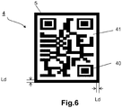
- a second non-limiting embodiment of a coded matrix symbol 4 As can be seen in the figure, in addition to the dark parts 40 and the light parts 41, the coded matrix symbol 4 is surrounded by a texture zone 5 d 'at least 2mm wide Ld integrally with the sidewall and contrasting with the rest of the tire 1. This delimitation zone 5 does not touch the dark zones 40 of the coded matrix symbol 4. It is made up of the same texture of the type "Velvet" (described in the remainder of the description) than the dark parts 40, so that the amount of black surface in the shooting zone around the coded matrix symbol 4 is increased.
- the dark parts 40 and the light parts 41 of the coded matrix symbol 4 are presented in the remainder of the description according to non-limiting embodiments.
- the dark parts 40 of the coded matrix symbol 4 are described below.
- the dark parts 40 are composed of a texture 400 integral with said sidewall 3.
- the texture 400 contrasts with the rest of the tire 1 and in particular the rest of the sidewall 3 of the tire 1 so that the coded matrix symbol 4 is indeed visible on the sidewall 3 by an observer of the tire.
- the texture 400 forming the dark parts 40 comprises a plurality of first elements 405 hollow relative to the surface 30 of the sidewall 3. These elements 405 are therefore also made of rubber material. In other words, a dark box 40 has a plurality of elements 405.
- the first hollow elements 405 (also called holes) of the texture 400 are presented below.
- the first recessed elements 405 are composed of openings 406 on the surface 30 of the sidewall 3 and associated cavities 407 extending into the depth of the surface 30 of the sidewall 3.
- the texture 400 comprises a plurality of openings 406 in the surface 30 of the sidewall 3, said openings 406 being distributed in the texture 400 according to a density at least equal to one opening per square millimeter (mm 2 ) and having on the surface 30 of the sidewall 3 of equivalent diameters Dt between 0.01 mm and 1.2 mm.
- the openings 406 occupy at least 30% of the texture. According to other non-limiting embodiments, the openings 406 occupy at least 50% of the texture, or even more than 70%. It will be noted that the greater the occupation rate of the openings on the texture, the better the quality of contrast of this texture and therefore of the dark parts 40 of the coded matrix symbol 4 with respect to the light parts 41 and the rest of the sidewall 3.
- the openings 406 extend into the depth of the surface 30 of the sidewall 3 to form cavities 407.
- cavities 407 The effect of these cavities 407 is to “trap” a large quantity of the incident light rays which encounter the texture, but also to offer greater durability of the texture. Indeed, as the cavities 407 are hollow in the surface 30 of the sidewall 3, the impact of mechanical attacks on the texture, such as friction of a roadway is lower than for protuberances.
- the texture (called “velvet”) makes it possible to obtain a visual of the “velvet” type because the cavities absorb light and thus make the dark parts 40 of the coded matrix symbol 4 blacker.
- all or part of the cavities 407 has a depth at least equal to 0.1mm. In a non-limiting variant embodiment, all or part of the cavities 407 has a depth of between 0.2 mm and 0.6 mm. In this way, it is ensured that a large quantity of incident light rays which meet the texture is trapped by said texture 400.
- the figure 7 illustrates the texture 400 according to a non-limiting variant embodiment.
- all or part of the cavities 407 are in the form of cones which extend in the depth of the surface 30 of the sidewall 3 and open out on said surface, forming circular openings 406.
- the cavities 407 thus have a section which decreases. in the depth of the surface 30 of the sidewall 3.
- the contrast of the texture 3 and therefore of the coded matrix symbol 4 is improved with respect to the rest of the tire 1 and more particularly with respect to the rest of the sidewall 3.
- the openings 406 of the cavities 407 do not touch.
- the openings 406 are separated by intermediate zones 408.
- the openings 406 are evenly distributed in the texture so that the distance d between each opening in the texture is generally similar.
- the figure 8 is a zoom on a cavity 407 of a hollow element 405 of the texture 400.
- all or part of the cavities has at least one wall 409 which, in a sectional view, forms an angle ⁇ between 10 ° and 60 ° with respect to a Z direction perpendicular to the texture.
- the direction of reflection of the light ray depends on the initial direction of this light ray and on the angle of inclination of the wall 409.
- the light ray can be returned to another wall 409 of the cavity.
- the light ray can be returned outside the cavity, for example directly towards an observer.
- the first case the light ray "gets lost" in the cavity and it will no longer be perceptible by the eye of an observer.
- the observer can perceive the light ray and the texture can then appear to be lighter and therefore less in contrast to the rest of the flank.
- the contrast of the texture (and therefore of the dark parts 40 of the coded matrix symbol 4) is improved with respect to the rest of the tire 1 (in particular compared to the light parts 41 and the rest of the sidewall 3), while retaining the same occupancy rate of the cavities in the texture 400.
- the overall resistance of the texture 400 is improved, in particular during repeated friction with the roadway.
- the first recessed elements 405 of the texture 400 are produced directly on the tire by laser engraving or molded by a part of a mold, said mold part having previously undergone a laser engraving operation of the mold to obtain said elements 405.
- the clear parts 41 are composed of a part of the surface 30 of the sidewall 3 which has not been covered by the texture 400 of the “velvet” type described above, part of the surface 30. of the flank delimited by the space 42 occupied by the coded matrix symbol 4.
- the surface 30 of the flank 3 is smooth and it reflects light. A tire observer goes perceive a gray-white color.
- the light parts 41 will be in contrast with respect to the dark parts 40 described previously.
- the figure 9 shows an enlarged perspective view of part of the pattern 410 comprising second hollow elements 411 according to a first non-limiting embodiment.
- the second recessed elements 411 all have the same shape. Shape is an open surface.
- the second recessed elements 411 are aligned with respect to each other. This makes it possible to clearly delimit the light parts 41.
- the figure 10 and the figure 11 show a sectional view of part of the second recessed elements 411 of the figure 9 .
- a second hollow element 411 has the shape of a part of a sphere. It is based on a sphere 413 which has a first radius R1. In sectional view, the geometric shape of the second recessed elements 411 is concave. Each second hollow element 411 is adjacent to another second hollow element 411. In addition, the second hollow elements 411 connect to each other at the level of connection zones 412.
- the distance d (also called “pitch”) between the equidistant point P1 of a hollow element 411 and the equidistant point P2 of another adjacent hollow element is less than the diameter of the sphere 413 on which the hollow element relies.
- the pitch d between two adjacent equidistant points P1-P2 of two adjacent hollow elements 411 is greater than or equal to 0.3mm and less than 2mm.
- the human eye at a distance greater than 2 meters, will perceive only a texture of the pattern 410 of uniform color.
- the pitch d between two adjacent vertices P1-P2 is equal to 1mm. This facilitates the industrial implementation of the hollow elements 411 and allows the use of inexpensive tooling.
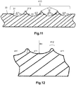
- the figure 10 presents a first non-limiting variant of an arrangement of the elements 411 relative to the surface of the sidewall 3, in which the connection zones 412 of the second hollow elements 411 are located at the same level as the average surface 31 of the sidewall 3 according to which the sidewall extends.
- the figure 11 presents a second non-limiting variant of an arrangement of the elements 411 relative to the surface of the sidewall 3, in which the connection zones 412 of the second hollow elements 411 extend above the sidewall. More particularly, the connection zones 412 extend above the mean surface 31 along which the sidewall extends.
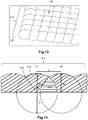
- the figure 12 shows an enlarged sectional view of a plurality of second recessed elements 411 of the pattern 410 according to a second embodiment in which the second recessed elements 411 are connected to each other at the level of connection zones 412, these connection zones 412 being curved and having a connection radius r1, such that r1 ⁇ R1 / 3.
- the humped elements 414 are presented below.
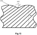
- the figure 13 shows an enlarged perspective view of part of the pattern 410 comprising second humped elements 414 according to a first non-limiting embodiment.
- the second humped elements 414 all have the same shape.
- the form is a closed surface.
- the shape is a spherical cap of second radius R2, also called shell or microlens.
- spherical cap is meant a cap whose second radius R2 is constant.
- the second radius R2 of the caps can be variable at plus or minus 10%.
- the humped elements 414 are aligned with respect to each other. This makes it possible to clearly delimit the light parts 41.
- the geometric shape of the humped elements 414 is thus convex.
- Each spherical cap 414 is interpenetrated with several adjacent hump elements.
- the distance d also called “pitch”
- the pitch d between two vertices S1-S2 is greater than or equal to 0.3mm and less than 2mm.
- the human eye at a distance greater than 2 meters, will perceive only a texture of the uniform color pattern.
- the pitch d between two vertices S1-S2 is equal to 1mm. This facilitates the industrial implementation of the caps and allows the use of inexpensive tools.
- the spherical caps 414 being interpenetrated with one another, they have a common zone 416 (illustrated by horizontal hatching). It can also be seen that, thanks to this architecture of interpenetrating spherical caps, the latter have limited inter-cap spaces 415, that is to say that these spaces have a reduced surface.
- connection zones 415 are curved and have a connection radius r2 , such that r2 ⁇ R2 / 3. In this way, the risks of propagation of cracks in the pattern 410, at the level of the connection zones, are limited.
- the second hollow elements 411 comprise an angular opening ⁇ less than or equal to 70 ° and the humped elements 413 include an angular opening a 'less than or equal to 70 °.
- the inter-shell spaces 415 are optimally reduced. If the opening a, a 'would be larger, this would entail a significant risk of absorption of light.
- the light rays incident on the second hollow elements 411 and on the spherical caps 414 are reflected towards the observer.
- the light is little absorbed by the texture of the sidewall 3 of the tire. There are therefore no so-called “black” regions.
- All of the hollow elements 411 and / or bump 414 make it possible to create so-called “white” regions due to the optimized reflection of light on said elements, a region corresponding to the light parts 41 of the coded matrix symbol 4.
- the second hollow elements 411 and the caps 414 have a texture which approaches a smooth, reflective surface, which regulates the average returned light intensity.
- the arithmetic mean deviation parameter Ra representative of the surface roughness is very low and is less than 30 ⁇ m.
- the light parts 41 thus have a surface roughness with a parameter Ra of less than 30 ⁇ m. The quantity of returned light is thus maximized.
- the density of hollow elements 411 and of bump elements 414 in the pattern 410 is greater than or equal to 0.2 elements. per mm 2 .
- the hollow elements 411 / bump 414 are molded by a part of a mold, said mold part having previously undergone a knurling operation for molding the hollow elements 411 / bump 414.
- the coded matrix symbol 4 comprises parts 41 which appear lighter to an observer of the tire 1 than the dark parts 40 and therefore clearly distinct by compared to these dark parts 40. This facilitates the reading / decoding of the coded matrix symbol 4.
- the pattern 410 may include a repetition of these same two shapes 411 and 414 which are alternated with each other, a hollow element 411 being positioned alternately with a hump element 414. There is a hollow element 411 adjacent to two hump elements. 414, and a humped element 414 adjacent to two recessed elements 411.
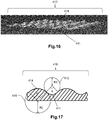
- the pattern 410 and consequently the light parts 41 of the coded matrix symbol 4 present in this alternation a variation in curvature of the cosine or sine type as illustrated. on the figure 17 .
- Such a pattern 410 makes it possible to mask any deformations of the sidewall such as hollows in the sidewall. Such deformations are in particular due to excess carcass ply, said ply making up the tire.
- Each hollow 411 and bump 414 element has the particular property of reflecting a quantity of light which remains constant, even when the pattern is tilted at a small angle with respect to an original position corresponding in the example to the position on the side without deformation.
- the inclination of the angle is less than 5 °, which corresponds to the inclination of the recess created by the sidewall deformation relative to the surface of the sidewall without deformation.
- the visual effect created by the hollow is practically no longer visible, or even not at all, whatever the position of an observer relative to the sidewall of the tire.
- the entire pattern makes it possible to create a homogeneous light reflection zone due to the optimized reflection of light on this pattern 410.
- the second radius R2 is such that 1/3 R1 ⁇ R2 ⁇ 3 R1. In a non-limiting variant embodiment, the second radius R2 is greater than the first radius R1. This configuration makes it possible, in the event of abrasion, to protect the hollow portion of the first ray R1 more effectively.
- the recessed elements 411 are aligned relative to each other and the humped elements 414 are aligned relative to each other.
- the vertices of the humped elements 414 are positioned along a mesh whose axes intersect at 90 °. This makes it possible to clearly delimit the light parts 41.
- a sectional view passing through the tops of the humped elements 414, the angular opening a 'of said elements 414 is equal to the angular opening ⁇ of the hollow elements 411 as illustrated in figure figure 17 .
- the set of elements 411-414 creates a homogeneous light reflection zone due to the optimized light reflection.
- the openings 406 of the figure 7 may have the shape of a circular, square, or even polygonal (for example hexagonal) and the corresponding cavities 407 a shape of cylinders, parallelepipeds, or even polygons.
- these last two structures square or polygonal
- the pattern 410 comprises second hollow elements 411 or bump 414 which are not aligned.
- the invention has been described with a coded matrix symbol.
- the flank 3 can include several coded matrix symbols.
- the production of the coded matrix symbol can be done in two steps: a step before cooking and a step after cooking.
- the light parts 41 are molded with the tire 1, therefore before curing, while the dark parts 40 are made on the cured tire, therefore after curing.
- the dark parts 40 are obtained by laser engraving on the cured tire.
Landscapes
- Engineering & Computer Science (AREA)
- Mechanical Engineering (AREA)
- Tires In General (AREA)
- Compositions Of Macromolecular Compounds (AREA)
Description
- La présente invention concerne un pneumatique en matériau caoutchoutique comportant un flanc.
- Il est connu du document
EP1636117 /WO2005000714 d'utiliser un symbole matriciel codé sur le flanc d'un pneumatique, ledit symbole matriciel codé comportant des informations telles qu'un numéro de série individuel pour ledit pneumatique, le site internet du constructeur du pneumatique, etc. Un symbole matriciel codé comporte des parties sombres et des parties claires et est gravé ici directement sur le flanc du pneumatique. - Le document
FR2995254 - Le document
EP2905125 relève de l'article 54(3) et divulgue un procédé de fabrication d'un symbole matriciel codé sur un pneumatique. - Le document
US2013068363 divulgue un pneumatique avec un flanc présentant une faible rugosité. - Le document
US4625101 divulgue un pneumatique comportant un code à bar directement moulé sur le flanc d'un pneumatique. - Il existe aujourd'hui un besoin pour améliorer la lisibilité des symboles matriciels codés présents sur les flancs de pneumatique en vue d'améliorer leur lecture.
-
- Par « pneumatique », on entend tous les types de bandages élastiques soumis à une pression interne ou non.
- Par « matériau caoutchoutique », on entend un élastomère diénique, c'est-à-dire de manière connue un élastomère issu d'au moins en partie (c'est-à-dire homopolymère ou un copolymère) de monomères diènes (monomères porteurs de deux doubles liaisons carbone-carbone, conjuguées ou non).
- Par « symbole matriciel codé », on entend un code dit « intelligent » où les données sont encodées en deux dimensions (sous la forme d'une pluralité de rangées et de colonnes), les données étant décodables par un imageur d'une machine, tel qu'un téléphone portable. Un symbole matriciel codé encode un volume nettement plus important de données pour une même surface donnée qu'un code barre linéaire traditionnel et comporte un système intégré de correction d'erreurs.
- Par « bande de roulement » d'un pneumatique, on entend une quantité de matériau caoutchoutique délimitée par des surfaces latérales et par deux surfaces principales dont l'une, appelée surface de roulement, est destinée à entrer en contact avec une chaussée lorsque le pneumatique roule.
- Par « flanc » d'un pneumatique, on entend une surface latérale du pneumatique disposée entre la bande de roulement du pneumatique et un bourrelet de ce pneumatique.
- Par « texture », on entend un agencement organisé d'une pluralité d'éléments, tout ou partie des éléments de l'agencement étant la répétition d'un même élément de base, par exemple, un brin ou une lamelle.
- Par « brin », on entend un élément filiforme dont la hauteur est au moins égale à 2 fois le diamètre d'un disque de même surface que la section moyenne du brin.
- Par « lamelles », on entend des brins allongés qui présentent une longueur au moins égale à deux fois leur hauteur.
- Par « texture venue de matière avec un flanc », on entend que la texture est dans le même matériau caoutchoutique que le flanc du pneumatique. On obtient ainsi une texture sans ajout d'un autre matériau.
- L'invention concerne un pneumatique en matériau caoutchoutique comprenant un flanc. Le flanc comporte un symbole matriciel codé, ledit symbole matriciel codé comprenant des parties sombres et des parties claires, les parties sombres étant composées d'une texture venue de matière avec ledit flanc et faisant contraste avec le reste du pneumatique. La texture est un agencement organisé d'une pluralité d'éléments. La texture comporte une pluralité de premiers éléments en creux par rapport à la surface du flanc. Les premiers éléments en creux forment des ouvertures sur la surface du flanc et la texture comprend une pluralité d'ouvertures, ces ouvertures étant réparties dans la texture selon une densité au moins égale à une ouverture par millimètre carré (mm2), ces ouvertures présentant des diamètres équivalents compris entre 0,01 mm et 1,2 mm.
- L'invention permet d'obtenir des parties sombres du symbole matriciel codé fortement en contraste par rapport aux parties claires de ce symbole. La lecture du symbole matriciel codé est ainsi améliorée. En outre, une telle texture venue de matière peut-être réalisée en même temps que la cuisson du pneumatique dans le moule, ce qui rend plus économique la fabrication du symbole matriciel.
- Selon des modes de réalisation non limitatifs, le pneumatique, peut comporter en outre une ou plusieurs caractéristiques supplémentaires parmi les suivantes.
- Dans un mode de réalisation non limitatif, le symbole matriciel codé est un symbole sélectionné parmi un ensemble de symboles comportant :
- un QR code.
- La texture permet de « piéger » tout ou partie des rayons lumineux incidents qui rencontrent le symbole matriciel codé. Ceci permet de donner un aspect plus noir aux parties sombres du symbole matriciel codé et en conséquence cela permet d'améliorer le contraste et donc leur visibilité par rapport aux parties claires et au reste du flanc. D'autre part, cette texture particulière permet d'obtenir un toucher agréable au niveau du symbole matriciel codé, de type « velours ».
- La texture présente ainsi une plus grande pérennité. En effet, comme cette texture est composée d'éléments en creux par rapport à la surface du flanc, l'impact de frottements d'une chaussée sur cette texture est plus faible.
- Dans un mode de réalisation non limitatif, les parties claires du symbole matriciel codé sont composées d'un motif comprenant une pluralité de deuxièmes éléments en creux et/ou en bosse, chaque élément en creux/bosse ayant la forme d'une partie de sphère.
- Les rayons lumineux provenant d'une même source lumineuse qui éclairent le flanc du pneumatique sont ainsi sensiblement déviés de la même manière sur le motif.
- Dans un mode de réalisation non limitatif, les deuxièmes éléments en creux se raccordent entre eux au niveau de zones de raccordement qui s'étendent au-dessus de la surface moyenne du flanc.
- Cela permet de constituer des éléments de protection des parties claires contre des phénomènes de frottements, issus par exemple de râpages trottoirs.
- Dans un mode de réalisation non limitatif, vue en coupe, tout ou partie des deuxièmes éléments en creux/en bosse comporte une ouverture angulaire inférieure ou égale à 70°.
- Cela permet d'obtenir une meilleure surface de réflexion pour la lumière. Les parties claires apparaissent ainsi plus clairement sur le flanc du pneumatique.
- Dans un mode de réalisation non limitatif, dans le motif, un deuxième élément en creux est positionné en alternance avec un élément en bosse, les parties claires du symbole matriciel codé présentant dans cette alternance une variation de courbure de type cosinus ou sinus.
- Les rayons lumineux provenant d'une même source lumineuse qui éclairent le flanc du pneumatique sont ainsi sensiblement déviés de la même manière sur le motif.
- Dans un mode de réalisation non limitatif, les parties claires du symbole matriciel codé comportent une rugosité de surface de paramètre Ra inférieur à 30 µm.
- Cela permet d'obtenir une surface proche d'une surface polie et ainsi de limiter la dispersion de la lumière.
- Dans un mode de réalisation non limitatif, le symbole matriciel codé est entouré d'une zone de texture d'au moins 2 mm de largeur venue de matière avec le flanc et faisant contraste avec le reste du pneumatique.
- Cela augmente le contraste entre les parties sombres et les parties claires du symbole matriciel codé. La lecture du symbole est en conséquence améliorée.
- Dans un mode de réalisation non limitatif, le symbole matriciel codé suit une courbure du flanc du pneumatique.
- Cela améliore l'esthétique du symbole matriciel codé sur le flanc du pneumatique.
- Dans un mode de réalisation non limitatif, le symbole matriciel codé est réalisé en creux dans le flanc du pneumatique.
- Cela améliore la protection du symbole matriciel codé contre l'usure provoquée, par exemple, par des râpages avec les trottoirs.
- D'autres caractéristiques et avantages de l'invention ressortiront de la description suivante, donnée à titre d'exemple, sans caractère limitatif, en regard des dessins annexés sur lesquels :
- la
figure 1 représente schématiquement une vue en perspective d'une partie d'un pneumatique comportant un flanc dans lequel est disposé un symbole matriciel codé conforme à l'invention selon un premier mode de réalisation non limitatif ; - la
figure 2 représente schématiquement une vue en perspective d'une partie d'un pneumatique comportant un flanc dans lequel est disposé un symbole matriciel codé conforme à l'invention selon un deuxième mode de réalisation non limitatif ; - la
figure 3 représente schématiquement une vue en coupe du flanc du pneumatique de lafigure 2 , dans lequel le symbole matriciel codé est encastré dans ledit flanc ; - la
figure 4 représente un symbole matriciel codé du flanc de lafigure 1 selon un mode de réalisation non limitatif, le symbole matriciel codé comprenant des parties sombres et des parties claires, les parties sombres étant composées d'une texture particulière ; - la
figure 5 représente l'espace occupé par le symbole matriciel codé de lafigure 3 sur le flanc du pneumatique ; - la
figure 6 représente le symbole matriciel codé du flanc de lafigure 2 entouré d'une zone de texture ; - la
figure 7 représente une partie de la texture composant des parties sombres du symbole matriciel codé de lafigure 4 ou6 , selon un cinquième mode de réalisation non limitatif ; - la
figure 8 représente une vue agrandie d'une cavité d'un élément en creux de la texture de lafigure 16 ; - la
figure 9 est une représentation en perspective d'une pluralité d'éléments en creux d'un motif composant des parties claires du symbole matriciel codé de lafigure 4 ou6 selon un premier mode de réalisation non limitatif ; - la
figure 10 représente schématiquement une vue en coupe d'une partie du motif de lafigure 9 selon une première variante de réalisation non limitative ; - la
figure 11 représente schématiquement une vue en coupe d'une partie du motif de lafigure 9 selon une deuxième variante de réalisation non limitative ; - la
figure 12 représente schématiquement une vue en coupe d'éléments en creux d'un motif composant des parties claires du symbole matriciel codé de lafigure 4 ou6 selon un deuxième mode de réalisation non limitatif ; - la
figure 13 est une représentation en perspective d'une pluralité d'éléments en bosse d'un motif composant des parties claires du symbole matriciel codé de lafigure 4 ou6 selon un premier mode de réalisation non limitatif ; - la
figure 14 représente schématiquement une vue en coupe d'une partie du motif de lafigure 13 ; - la
figure 15 représente schématiquement une vue en coupe d'éléments en bosse d'un motif composant des parties claires du symbole matriciel codé de lafigure 4 ou6 selon un deuxième mode de réalisation non limitatif ; - la
figure 16 est une représentation en perspective d'une pluralité d'éléments en creux et en bosse d'un motif composant des parties claires du symbole matriciel codé de lafigure 4 ou6 selon un mode de réalisation non limitatif ; et - la
figure 17 représente schématiquement une vue en coupe d'une partie du motif de lafigure 16 . - Dans la description qui va suivre, des éléments sensiblement identiques ou similaires seront désignés par des références identiques.
- La
figure 1 illustre le flanc 3 d'un pneumatique 1, ledit flanc 3 comprenant un symbole matriciel codé 4. - Dans un mode de réalisation non limitatif, le symbole matriciel codé 4 est sélectionné parmi les symboles suivants :
- un QR code.
- Le symbole matriciel codé 4 permet d'encoder des informations telles que la marque du constructeur, le site internet du constructeur etc. Grâce à des moyens de lecture/décodage tels qu'un imageur intégré dans un exemple non limitatif dans un téléphone portable, un observateur du pneumatique va pouvoir lire et décoder le symbole matriciel codé 4 et accéder au site internet du constructeur, par exemple pour commander un nouveau pneumatique.
- Tel qu'illustré sur la
figure 2 , dans un mode de réalisation non limitatif, le symbole matriciel codé 4 suit la courbure C1 du flanc 3 de pneumatique 1, ladite courbure étant définie selon un parallèle par rapport à l'axe de rotation du pneumatique. Autrement dit, le symbole matriciel codé 4 est courbé autour de l'axe de rotation du pneumatique 1. Cela donne un aspect plus esthétique au pneumatique puisque le symbole matriciel codé 4 apparaît comme faisant partie intégrante du flanc 3. - Dans un mode de réalisation non limitatif tel qu'illustré sur la vue en coupe de la
figure 3 , le symbole matriciel codé 4 est réalisé en creux dans le flanc 3 du pneumatique. Le flanc 3 comporte un logement 43 dans lequel est encastré le symbole matriciel codé 4. Les parties sombres 40 (composées d'éléments en en creux 405 décrits plus loin dans la description) ainsi que les parties claires 41 (qu'elles soient composées d'éléments en bosse 414 ou en creux 411 décrits plus loin dans la description) s'étendent au-dessous de la surface 30 du flanc 3, ladite surface étant la surface supérieure du flanc. Ainsi, le fait que ces éléments ne remontent pas jusqu'au niveau de la surface 30 du flanc 3 permet d'avoir un symbole matriciel codé 4 plus robuste notamment lors de râpage trottoir. Par ailleurs, cela perturbe moins l'écoulement de l'air qui est ainsi plus fluide et qui suit donc mieux ladite surface 30 du flanc 3. - Sur la
figure 4 est représenté un premier mode de réalisation non limitatif de symbole matriciel codé 4. Comme on peut le voir sur la figure, le symbole matriciel codé 4 comporte des parties sombres 40 et des parties claires 41. De façon connue de l'homme du métier, dans un mode de réalisation non limitatif, les parties sombres 40 et claires 41 sont des cases sombres, respectivement des cases claires, une partie correspondant à une case. Le symbole matriciel codé 4 comporte ainsi des colonnes et des rangées de cases (ou carrés). Dans un mode de réalisation non limitatif, une case comporte une taille comprise entre 0,5x0,5mm à 2x2mm. Au-delà, le symbole matriciel codé 4 devient trop intrusif ou est bien trop miniaturisé et donc trop fragile pour être décodé en fin d'usure du pneumatique 1. Dans une variante de réalisation non limitative, une case comporte une taille de 1x1mm. Dans un autre mode de réalisation non limitatif, les parties sombres 40 et claires 41 sont des ronds sombres, respectivement des ronds clairs. Dans un autre mode de réalisation non limitatif, on peut avoir une combinaison de cases et de ronds. Le symbole matriciel codé 4 occupe un espace 42 sur le flanc 3 du pneumatique 1, illustré sur lafigure 5 . - Sur la
figure 6 est représenté un deuxième mode de réalisation non limitatif de symbole matriciel codé 4. Comme on peut le voir sur la figure, outre les parties sombres 40 et les parties claires 41, le symbole matriciel codé 4 est entouré d'une zone de texture 5 d'au moins 2mm de largeur Ld venue de matière avec le flanc et faisant contraste avec le reste du pneumatique 1. Cette zone de délimitation 5 ne touche pas les zones sombres 40 du symbole matriciel codé 4. Elle est composée de la même texture de type « velours » (décrite dans la suite de la description) que les parties sombres 40, de sorte que la quantité de surface noire dans la zone de prise de vue autour du symbole matriciel codé 4 est augmentée. - Ainsi, en augmentant ainsi la quantité de surface noire, on augmente le contraste entre les régions claires et sombres du symbole matriciel 4 dans le traitement réalisé par le téléphone portable. On améliore par conséquent la lecture/décodage du symbole 4.
- Les parties sombres 40 et les parties claires 41 du symbole matriciel codé 4 sont présentées dans la suite de la description selon des modes de réalisation non limitatifs.
- Les parties sombres 40 du symbole matriciel codé 4 sont décrites ci-après.
- Les parties sombres 40 sont composées d'une texture 400 venue de matière avec ledit flanc 3. La texture 400 fait contraste avec le reste du pneumatique 1 et notamment le reste du flanc 3 du pneumatique 1 de sorte que le symbole matriciel codé 4 soit bien visible sur le flanc 3 par un observateur du pneumatique.
- La texture 400 formant les parties sombres 40 comporte une pluralité de premiers éléments en creux 405 par rapport à la surface 30 du flanc 3. Ces éléments 405 sont donc également en matière caoutchoutique. Autrement dit, une case sombre 40 comporte une pluralité d'éléments 405.
- Les premiers éléments en creux 405 (appelés également trous) de la texture 400 sont présentés ci-après.
- Les premiers éléments en creux 405 sont composés d'ouvertures 406 sur la surface 30 du flanc 3 et de cavités 407 associées s'étendant dans la profondeur de la surface 30 du flanc 3.
- Ainsi, la texture 400 comprend une pluralité d'ouvertures 406 dans la surface 30 du flanc 3, lesdites ouvertures 406 étant réparties dans la texture 400 selon une densité au moins égale à une ouverture par millimètre carré (mm2) et présentant sur la surface 30 du flanc 3 des diamètres Dt équivalents compris entre 0,01 mm et 1,2 mm.
- Dans un mode de réalisation non limitatif, les ouvertures 406 occupent au moins 30% de la texture. Selon d'autres modes de réalisation non limitatifs, les ouvertures 406 occupent au moins 50% de la texture, voire plus de 70%. On notera que plus le taux d'occupation des ouvertures sur la texture est important, meilleure est la qualité de contraste de cette texture et donc des parties sombres 40 du symbole matriciel codé 4 par rapport aux parties claires 41 et au reste du flanc 3.
- Les ouvertures 406 se prolongent dans la profondeur de la surface 30 du flanc 3 pour former des cavités 407.
- L'effet de ces cavités 407 est de « piéger » une grande quantité des rayons lumineux incidents qui rencontrent la texture, mais également d'offrir une plus grande pérennité de la texture. En effet, comme les cavités 407 sont en creux dans la surface 30 du flanc 3, l'impact des agressions mécaniques sur la texture, tels que des frottements d'une chaussée est plus faible que pour des protubérances. Dans ce mode de réalisation, la texture (appelée «velours ») permet d'obtenir un visuel de type « velours » car les cavités absorbent la lumière et rendent ainsi les parties sombres 40 du symbole matriciel codé 4 plus noires.
- Dans un mode de réalisation non limitatif, tout ou partie des cavités 407 a une profondeur au moins égale à 0.1mm. Dans une variante de réalisation non limitative, tout ou partie des cavités 407 a une profondeur comprise entre 0.2 mm et 0.6 mm. De cette manière, on s'assure qu'une grande quantité de rayons lumineux incidents qui rencontre la texture est piégée par ladite texture 400.
- La
figure 7 illustre la texture 400 selon une variante de réalisation non limitative. Dans cette variante, tout ou partie des cavités 407 sont en forme de cônes qui s'étendent dans la profondeur de la surface 30 du flanc 3 et débouchent sur ladite surface en formant des ouvertures circulaires 406. Les cavités 407 ont ainsi une section qui diminue dans la profondeur de la surface 30 du flanc 3. De cette manière, on améliore le contraste de la texture 3 et donc du symbole matriciel codé 4 par rapport au reste du pneumatique 1 et plus particulièrement par rapport au reste du flanc 3. On notera que dans cette variante, les ouvertures 406 des cavités 407 ne se touchent pas. Les ouvertures 406 sont séparées par des zones intermédiaires 408. En outre, les ouvertures 406 sont régulièrement réparties dans la texture de sorte que la distance d entre chaque ouverture de la texture est globalement similaire. - La
figure 8 est un zoom sur une cavité 407 d'un élément en creux 405 de la texture 400. Dans un mode de réalisation non limitatif, tout ou partie des cavités a au moins une paroi 409 qui, selon une vue en coupe, forme un angle β compris entre 10° et 60° par rapport à une direction Z perpendiculaire à la texture. - A chaque fois qu'un rayon lumineux rencontre une paroi 409 de la cavité 407, celui-ci est réfléchi par ladite paroi 409. La direction de réflexion du rayon lumineux dépend de la direction initiale de ce rayon lumineux et de l'angle d'inclinaison de la paroi 409. Ainsi, en fonction de cette direction initiale et de cet angle d'inclinaison, le rayon lumineux peut être renvoyé vers une autre paroi 409 de la cavité. A l'inverse, le rayon lumineux peut être renvoyé à l'extérieur de la cavité, par exemple directement vers un observateur. Dans le premier cas, le rayon lumineux « se perd » dans la cavité et il ne sera plus perceptible par l'œil d'un observateur. Dans le second cas, l'observateur peut percevoir le rayon lumineux et la texture peut apparaître alors comme étant plus claire et donc moins en contraste vis-à-vis du reste du flanc. En choisissant une cavité 407 ayant au moins une paroi 409 qui forme un angle β compris entre 10° et 60°, on s'assure qu'une grande partie des rayons lumineux rentrant dans la cavité 407 va être absorbée par cette cavité sous l'effet de réflexions multiples à l'intérieur de la cavité. De cette manière, on améliore le contraste de la texture (et donc des parties sombres 40 du symbole matriciel codé 4) par rapport au reste du pneumatique 1 (notamment par rapport aux parties claires 41 et au reste du flanc 3), tout en conservant le même taux d'occupation des cavités dans la texture 400. En outre, avec cette inclinaison de paroi, on améliore globalement la résistance de la texture 400, notamment lors de frottements répétés avec la chaussée.
- Dans un exemple non limitatif, les premiers éléments en creux 405 de la texture 400 sont directement fabriqués sur le pneumatique par gravure laser ou moulés par une partie d'un moule, ladite partie de moule ayant préalablement subi une opération de gravure laser du moule pour obtenir lesdits éléments 405.
- En référence aux
figures 9 à 17 , les parties claires 41 du symbole matriciel codé 4 sont décrites ci-après. - Dans un premier mode de réalisation non limitatif, les parties claires 41 sont composées d'une partie de la surface 30 du flanc 3 qui n'a pas été recouverte par la texture 400 de type « velours » décrite précédemment, partie de la surface 30 du flanc délimitée par l'espace 42 occupé par le symbole matriciel codé 4. En effet, la surface 30 du flanc 3 est lisse et elle réfléchit la lumière. Un observateur du pneumatique va percevoir une couleur gris-blanc. Ainsi, les parties claires 41 seront en contraste par rapport aux parties sombres 40 décrites précédemment.
- Dans un deuxième mode de réalisation non limitatif, les parties claires 41 sont composées d'un motif 410 comprenant :
- une pluralité de deuxièmes éléments en creux 411 ; ou
- une pluralité de deuxièmes éléments en bosse 414 ; ou
- une combinaison de deuxièmes éléments en creux 411 et de deuxièmes éléments en bosse 414.
- Les différents éléments 411 et 414, et leur combinaison sont décrits ci-dessous.
- En référence aux
figures 9 à 12 , les deuxièmes éléments en creux 411 sont présentés ci-après. - La
figure 9 montre une vue agrandie en perspective d'une partie du motif 410 comprenant des deuxièmes éléments en creux 411 selon un premier mode de réalisation non limitatif. Les deuxièmes éléments en creux 411 ont tous la même forme. La forme est une surface ouverte. Dans le mode de réalisation non limitatif illustré à lafigure 9 , les deuxièmes éléments en creux 411 sont alignés les uns par rapport aux autres. Ceci permet de bien délimiter les parties claires 41. - La
figure 10 et lafigure 11 montrent une vue en coupe d'une partie des deuxièmes éléments en creux 411 de lafigure 9 . Un deuxième élément en creux 411 a la forme d'une partie de sphère. Il s'appuie sur une sphère 413 qui présente un premier rayon R1. En vue en coupe, la forme géométrique des deuxièmes éléments en creux 411 est concave. Chaque deuxième élément en creux 411 est adjacent avec un autre deuxième élément en creux 411. De plus, les deuxièmes éléments en creux 411 se raccordent entre eux au niveau de zones de raccordement 412. - La distance d (appelée également « pas ») entre le point équidistant P1 d'un élément en creux 411 et le point équidistant P2 d'un autre élément en creux adjacent est inférieure au diamètre de la sphère 413 sur lequel l'élément en creux s'appuie. Dans un mode de réalisation non limitatif, le pas d entre deux points équidistants adjacents P1-P2 de deux éléments en creux adjacents 411 est supérieur ou égal à 0,3mm et inférieur à 2mm. Ainsi, l'œil humain, à une distance supérieure à 2 mètres ne va percevoir qu'une texture du motif 410 de couleur uniforme. Dans un exemple de réalisation non limitatif, le pas d entre deux sommets adjacents P1-P2 est égal à 1mm. Cela facilite la mise en œuvre au niveau industriel des éléments en creux 411 et permet d'utiliser un outillage peu coûteux.
- La
figure 10 présente une première variante de réalisation non limitative d'une disposition des éléments 411 par rapport à la surface du flanc 3, dans lequel les zones de raccordement 412 des deuxièmes éléments en creux 411 se situent au même niveau que la surface moyenne 31 du flanc 3 selon laquelle le flanc s'étend. - La
figure 11 présente une deuxième variante de réalisation non limitative d'une disposition des éléments 411 par rapport à la surface du flanc 3, dans lequel les zones de raccordement 412 des deuxièmes éléments en creux 411 s'étendent au-dessus du flanc. Plus particulièrement, les zones de raccordement 412 s'étendent au-dessus de la surface moyenne 31 selon laquelle le flanc s'étend. - La
figure 12 montre une vue agrandie en coupe d'une pluralité de deuxièmes éléments en creux 411 du motif 410 selon un deuxième mode de réalisation dans lequel les deuxièmes éléments en creux 411 se raccordent entre eux au niveau de zones de raccordement 412, ces zones de raccordement 412 étant courbes et présentant un rayon de raccordement r1, tel que r1≤ R1/3. - En référence aux
figures 13 à 15 , les éléments en bosse 414 sont présentés ci-après. - La
figure 13 montre une vue agrandie en perspective d'une partie du motif 410 comprenant des deuxièmes éléments en bosse 414 selon un premier mode de réalisation non limitatif. Les deuxièmes éléments en bosse 414 ont tous la même forme. La forme est une surface fermée. La forme est une calotte sphérique de deuxième rayon R2, également appelée coque ou microlentille. On entend par calotte sphérique, une calotte dont le deuxième rayon R2 est constant. En variante, le deuxième rayon R2 des calottes peut être variable à plus ou moins 10%. Dans le mode de réalisation non limitatif illustré à lafigure 13 , les éléments en bosse 414 sont alignés les uns par rapport aux autres. Ceci permet de bien délimiter les parties claires 41. - En vue en coupe
figure 14 , la forme géométrique des éléments en bosse 414est ainsi convexe. Chaque calotte sphérique 414 est interpénétrée avec plusieurs éléments en bosse adjacents. Ainsi, comme illustré sur lafigure 14 , la distance d (appelée également «pas ») entre le sommet SI d'une calotte sphérique et le sommet S2 d'une autre calotte sphérique adjacente est inférieure au diamètre D de cette calotte sphérique. Dans un mode de réalisation non limitatif, le pas d entre deux sommets S1-S2 est supérieur ou égal à 0,3mm et inférieur à 2mm. Ainsi, l'œil humain, à une distance supérieure à 2 mètres ne va percevoir qu'une texture du motif de couleur uniforme. Dans un exemple de réalisation non limitatif, le pas d entre deux sommets S1-S2 est égal à 1mm. Cela facilite la mise en œuvre au niveau industriel des calottes et permet d'utiliser un outillage peu coûteux. - Comme on peut le voir sur la
figure 14 , les calottes sphériques 414 étant interpénétrées entre elles, elles présentent une zone commune 416 (illustrée par des hachures horizontales). On peut également voir que grâce à cette architecture de calottes sphériques interpénétrées, ces dernières présentent des espaces inter-calottes 415 limités, c'est-à-dire que ces espaces présentent une surface réduite. - La
figure 15 présente un deuxième mode de réalisation non limitatif des éléments en bosse 414 dans lequel, lesdits éléments 414 se raccordent au niveau des espaces inter-calottes 415 appelées également zones de raccordement 415. Ces zones de raccordement 415 sont courbes et présentent un rayon de raccordement r2, tel que r2 ≤ R2/3. De cette manière, on limite les risques de propagation de fissures dans le motif 410, au niveau des zones de raccordement. - Afin d'améliorer davantage le renvoi de lumière par la texture (ce qui permet de faire apparaître les parties 41 du symbole matriciel codé 4 encore plus claires), on utilise les modes de réalisation non limitatifs suivants.
- Dans un mode de réalisation non limitatif, les deuxièmes éléments en creux 411 comportent une ouverture angulaire α inférieure ou égale à 70° et les éléments en bosse 413 comportent une ouverture angulaire a' inférieure ou égale à 70°. Dans ce dernier cas, on réduit de façon optimum les espaces inter-calottes 415. Dans le cas où l'ouverture a, a' serait plus grande, cela entraînerait un risque d'absorption de lumière important.
- Les rayons lumineux incidents sur les deuxièmes éléments en creux 411 et sur les calottes sphériques 414, sont réfléchis vers l'observateur. La lumière est peu absorbée par la texture du flanc 3 du pneumatique. Il n'y a donc pas de régions dites « noires ». L'ensemble des éléments en creux 411 et/ou en bosse 414 permettent de créer des régions dites « blanches » en raison de la réflexion optimisée de la lumière sur lesdits éléments, région correspondant aux parties claires 41 du symbole matriciel codé 4.
- Dans un mode de réalisation non limitatif, les deuxièmes éléments en creux 411 et les calottes 414 présentent une texture qui se rapproche d'une surface lisse, réfléchissante, qui régularise l'intensité lumineuse moyenne renvoyée. Le paramètre écart-moyen arithmétique Ra représentatif de la rugosité de surface est très faible et est inférieur à 30µm. Les parties claires 41 comportent ainsi une rugosité de surface de paramètre Ra inférieur à 30 µm. La quantité de lumière renvoyée est ainsi maximisée.
- Afin d'obtenir un procédé de fabrication facile à mettre en œuvre, dans un mode de réalisation non limitatif, la densité d'éléments en creux 411 et d'éléments en bosse 414 dans le motif 410 est supérieure ou égale à 0,2 éléments par mm2. Dans un exemple non limitatif, les éléments en creux 411/en bosse 414 sont moulés par une partie d'un moule, ladite partie de moule ayant préalablement subi une opération de moletage pour le moulage des éléments en creux 411/en bosse 414.
- Cela permet également de réaliser des éléments 411, 414 alignés dans les parties claires 41 selon au moins une direction préférentielle et ceci d'une manière simple et économique. Par ailleurs, cela permet de donner aux parties claires 41 un aspect plus uniforme vis-à-vis d'un observateur.
- Ainsi, grâce à ces deuxièmes éléments en creux 411/en bosse 414, le symbole matriciel codé 4 comporte des parties 41 qui apparaissent plus claires pour un observateur du pneumatique 1 que les parties sombres 40 et donc bien distinctes par rapport à ces parties sombres 40. Cela facilite la lecture/décodage du symbole matriciel codé 4.
- En référence aux
figures 16 et 17 , la combinaison des deuxièmes éléments en creux 411 et des éléments en bosse 414 sont présentés ci-après. - Le motif 410 peut comporter une répétition de ces deux mêmes formes 411 et 414 qui sont alternées entre elles, un élément en creux 411 étant positionné en alternance avec un élément en bosse 414. On a un élément en creux 411 adjacent à deux éléments en bosse 414, et un élément en bosse 414 adjacent à deux éléments en creux 411. Ainsi, le motif 410 et par conséquent les parties claires 41 du symbole matriciel codé 4 présentent dans cette alternance une variation de courbure de type cosinus ou sinus tel qu'illustré sur la
figure 17 . - Un tel motif 410 permet de masquer d'éventuelles déformations du flanc telles que des creux sur le flanc. De telles déformations sont notamment dues à des surplus de nappe carcasse, ladite nappe composant le pneumatique. Chaque élément en creux 411 et en bosse 414 a la propriété particulière de renvoyer une quantité de lumière qui reste constante, même lorsque le motif est incliné d'un faible angle par rapport à une position d'origine correspondant dans l'exemple à la position sur le flanc sans déformation. Dans un exemple non limitatif, l'inclinaison de l'angle est inférieure à 5°, ce qui correspond à l'inclinaison du renfoncement créé par la déformation flanc par rapport à la surface du flanc sans déformation. L'effet visuel créé par le creux n'est pratiquement plus visible voire plus du tout, quel que soit la position d'un observateur par rapport au flanc du pneumatique. L'ensemble du motif permet de créer une zone de réflexion lumineuse homogène en raison de la réflexion optimisée de la lumière sur ce motif 410.
- Le deuxième rayon R2 est tel que 1/3 R1 < R2 < 3 R1. Dans une variante de réalisation non limitative, le deuxième rayon R2 est supérieur au premier rayon R1. Cette configuration permet en cas d'abrasion de protéger plus efficacement la partie en creux de premier rayon R1.
- Dans un mode de réalisation non limitatif illustré à la
figure 16 , dans le motif 410, les éléments en creux 411 sont alignés les uns par rapport aux autres et les éléments en bosse 414 sont alignés les uns par rapport aux autres. Autrement dit, les sommets des éléments en bosse 414 sont positionnés selon un maillage dont les axes se croisent à 90°. Ceci permet de bien délimiter les parties claires 41. - Dans un mode de réalisation non limitatif, vue en coupe passant par les sommets des éléments en bosse 414, l'ouverture angulaire a' desdits éléments 414 est égale à l'ouverture angulaire α des éléments en creux 411 tel qu'illustré sur la
figure 17 . Cela permet d'avoir une continuité dans une partie claire 41 sans point anguleux entre un élément en creux 411 et un élément en bosse 414. - L'ensemble des éléments 411-414 permet de créer une zone de réflexion lumineuse homogène en raison de la réflexion optimisée de la lumière.
- L'invention n'est pas limitée aux exemples décrits et représentés et diverses modifications peuvent y être apportées sans sortir de son cadre.
- Ainsi, selon une autre variante de réalisation non limitative, les ouvertures 406 de la
figure 7 peuvent avoir la forme circulaire, carrée, ou encore polygonales (par exemple hexagonales) et les cavités 407 correspondantes une forme de cylindres, de parallélépipèdes, ou encore de polygones. Avec ces deux dernières structures (carrée ou polygonale), il est possible d'organiser plus facilement les ouvertures 406 les unes par rapport aux autres de sorte à limiter la surface des zones intermédiaires 408 entre ces ouvertures. Avec de telles formes d'ouvertures, on peut arriver plus aisément à des taux conséquents d'occupation des ouvertures. - Ainsi, selon une autre variante de réalisation non limitative, le motif 410 comprend des deuxièmes éléments en creux 411 ou en bosse 414 non alignés.
- Ainsi, l'invention a été décrite avec un symbole matriciel codé. Cependant, dans un autre exemple de réalisation, le flanc 3 peut comporter plusieurs symboles matriciels codés.
- Ainsi, selon une autre variante de réalisation non limitative, la réalisation du symbole matriciel codé peut être faite en deux étapes : une étape avant cuisson et une étape après cuisson. Les parties claires 41 sont moulées avec le pneumatique 1, donc avant cuisson, tandis que les parties sombres 40 sont réalisées sur le pneumatique cuit, donc en après cuisson. Les parties sombres 40 sont obtenues par gravure laser sur le pneumatique cuit.
- L'invention décrite présente notamment les avantages suivants :
- la texture des parties sombres 41 du symbole matriciel codé 4 (avec des premiers éléments en creux) permet d'absorber la lumière et donc de donner un aspect plus noir aux parties sombres. On améliore ainsi le contraste des parties sombres 40 par rapport :
- au reste du flanc 3 du pneumatique, ce qui permet de bien distinguer le symbole matriciel codé 4 sur le flanc 3 ;
- aux parties claires 41, ce qui permet de bien distinguer les parties sombres des parties claires, et donc de faciliter la lecture/décodage du symbole matriciel codé. Les erreurs de lecture/décodage par un imageur sont ainsi réduites.
- grâce à la composition du symbole matriciel codé 4 avec une texture type « velours » pour les parties sombres 40 et avec des deuxièmes éléments en creux/en bosse pour les parties claires 41, la fabrication du symbole matriciel codé 4 peut être intégré lors de la fabrication du pneumatique 1 au moyen d'un moule intégré, et non pas après la fabrication du pneumatique. La réalisation est ainsi simplifiée et le coût est réduit.
- la texture de type « velours » des parties sombres 41 permet :
- au symbole matriciel codé 4 d'avoir une texture agréable au toucher ;
- d'obtenir un symbole matriciel codé 4 robuste et qui ne se déforme pas. Le symbole matriciel codé 4 s'use beaucoup moins qu'un symbole matriciel gravé Le décodage du symbole 4 sera toujours efficace même après usure du pneumatique ;
- la zone de texture 5 entourant le symbole matriciel codé 4 permet de bien cibler l'emplacement du symbole 4 et donc des données à décoder. Le traitement du symbole 4 est ainsi facilité.
- la composition (avec les deuxièmes éléments en creux/en bosse) des parties claires 41 du symbole matriciel codé 4 permet également d'améliorer leur contraste vis-à-vis des parties sombres 40.
Cela permet de rendre encore plus claires les parties 41 que la surface lisse du flanc 3.
Le motif 410 est également venu de matière avec ledit flanc 3. Il est dans le même matériau caoutchoutique que le flanc du pneumatique. Les éléments 411 et 414 sont donc en matière caoutchoutique.
Claims (12)
- Pneumatique (1) en matériau caoutchoutique comprenant un flanc (3), le flanc (3) comportant un symbole matriciel codé (4), ledit symbole matriciel codé (4) comprenant des parties sombres (40) et des parties claires (41), caractérisé en ce que les parties sombres (40) sont composées d'une texture (400) venue de matière avec ledit flanc (3) et faisant contraste avec le reste du pneumatique (1), ladite texture étant un agencement organisé d'une pluralité d'éléments (401, 402, 403, 404, 405, 411, 414) et en ce que la texture (400) comporte une pluralité de premiers éléments en creux (405) par rapport à la surface du flanc (3) et en ce que les premiers éléments en creux (405) forment des ouvertures (406) sur la surface du flanc (3) et la texture comprend une pluralité d'ouvertures (406), ces ouvertures étant réparties dans la texture selon une densité au moins égale à une ouverture par millimètre carré (mm2), ces ouvertures présentant des diamètres équivalents compris entre 0,01 mm et 1,2 mm.
- Pneumatique (1) selon la revendication 1, caractérisé en ce que le symbole matriciel codé (4) est un QR code.
- Pneumatique (1) selon l'une quelconque des revendications 1 à 2, caractérisé en ce que les parties claires (41) du symbole matriciel codé (4) sont composées d'un motif (410) comprenant une pluralité de deuxièmes éléments en creux (411) et/ou en bosse (414), chaque élément en creux (411)/bosse (414) ayant la forme d'une partie de sphère.
- Pneumatique (1) selon la revendication 3, caractérisé en ce que les deuxièmes éléments en creux (411) se raccordent entre eux au niveau de zones de raccordement (412) qui s'étendent au-dessus du flanc (3).
- Pneumatique (1) selon l'une quelconque des revendications 3 ou 4, caractérisé en ce que vue en coupe, tout ou partie des deuxièmes éléments en creux (411)/en bosse (414) comporte une ouverture angulaire (α, α') inférieure ou égale à 70°.
- Pneumatique (1) selon l'une quelconque des revendications 1 à 5, caractérisé en ce que les parties claires (41) du symbole matriciel codé (4) comportent une rugosité de surface de paramètre Ra inférieur à 30 µm.
- Pneumatique (1) selon l'une quelconque des revendications 1 à 6, caractérisé en ce que le symbole matriciel codé (4) est entouré d'une zone (5) de texture d'au moins 2 mm de largeur (Ld) venue de matière avec le flanc (3) et faisant contraste avec le reste du pneumatique (1).
- Pneumatique (1) selon l'une quelconque des revendications 1 à 7, caractérisé en ce que le symbole matriciel codé (4) suit une courbure (C1) du flanc (3) du pneumatique (1), ladite courbure étant définie selon un parallèle par rapport à l'axe de rotation du pneumatique, le symbole matriciel codé (4) étant courbé autour de l'axe de rotation dudit pneumatique (1).
- Pneumatique selon l'une quelconque des revendications 1 à 8, caractérisé en ce que le symbole matriciel codé (4) est réalisé en creux dans le flanc (3) du pneumatique (1).
- Pneumatique selon l'une quelconque des revendications 1 à 9, caractérisé en ce que les ouvertures (406) sont circulaires.
- Pneumatique selon l'une quelconque des revendications 1 à 10, caractérisé en ce que les ouvertures sont régulièrement réparties dans la texture.
- Pneumatique selon l'une quelconque des revendications 1 à 11, caractérisé en ce que les ouvertures (406) se prolongent dans la profondeur de la surface (30) du flanc 3 pour former des cavités (407), tout ou partie des cavités a au moins une paroi (409) qui, selon une vue en coupe, forme un angle β compris entre 10° et 60° par rapport à une direction Z perpendiculaire à la texture.
Priority Applications (1)
| Application Number | Priority Date | Filing Date | Title |
|---|---|---|---|
| EP20179537.4A EP3741585B1 (fr) | 2014-04-30 | 2015-04-28 | Pneumatique comportant un symbole matriciel a fort contraste sur le flanc |
Applications Claiming Priority (2)
| Application Number | Priority Date | Filing Date | Title |
|---|---|---|---|
| FR1453987A FR3020594B1 (fr) | 2014-04-30 | 2014-04-30 | Pneumatique comportant un symbole matriciel a fort contraste sur le flanc |
| PCT/EP2015/059122 WO2015165863A1 (fr) | 2014-04-30 | 2015-04-28 | Pneumatique comportant un symbole matriciel a fort contraste sur le flanc |
Related Child Applications (2)
| Application Number | Title | Priority Date | Filing Date |
|---|---|---|---|
| EP20179537.4A Division EP3741585B1 (fr) | 2014-04-30 | 2015-04-28 | Pneumatique comportant un symbole matriciel a fort contraste sur le flanc |
| EP20179537.4A Division-Into EP3741585B1 (fr) | 2014-04-30 | 2015-04-28 | Pneumatique comportant un symbole matriciel a fort contraste sur le flanc |
Publications (2)
| Publication Number | Publication Date |
|---|---|
| EP3137318A1 EP3137318A1 (fr) | 2017-03-08 |
| EP3137318B1 true EP3137318B1 (fr) | 2020-07-29 |
Family
ID=51168186
Family Applications (2)
| Application Number | Title | Priority Date | Filing Date |
|---|---|---|---|
| EP15720316.7A Active EP3137318B1 (fr) | 2014-04-30 | 2015-04-28 | Pneumatique comportant un symbole matriciel a fort contraste sur le flanc |
| EP20179537.4A Active EP3741585B1 (fr) | 2014-04-30 | 2015-04-28 | Pneumatique comportant un symbole matriciel a fort contraste sur le flanc |
Family Applications After (1)
| Application Number | Title | Priority Date | Filing Date |
|---|---|---|---|
| EP20179537.4A Active EP3741585B1 (fr) | 2014-04-30 | 2015-04-28 | Pneumatique comportant un symbole matriciel a fort contraste sur le flanc |
Country Status (8)
| Country | Link |
|---|---|
| US (1) | US20170050473A1 (fr) |
| EP (2) | EP3137318B1 (fr) |
| JP (2) | JP2017516698A (fr) |
| CN (1) | CN106457928B (fr) |
| BR (1) | BR112016024993B1 (fr) |
| DE (2) | DE202015009344U1 (fr) |
| FR (3) | FR3020594B1 (fr) |
| WO (1) | WO2015165863A1 (fr) |
Families Citing this family (56)
| Publication number | Priority date | Publication date | Assignee | Title |
|---|---|---|---|---|
| FR3020594B1 (fr) | 2014-04-30 | 2018-01-05 | Compagnie Generale Des Etablissements Michelin | Pneumatique comportant un symbole matriciel a fort contraste sur le flanc |
| EP3095596A1 (fr) | 2015-05-21 | 2016-11-23 | 4JET Technologies GmbH | Motif d'évidements dans un article en caoutchouc |
| JP6489945B2 (ja) * | 2015-06-04 | 2019-03-27 | 株式会社ブリヂストン | タイヤ |
| JP6694282B2 (ja) | 2016-01-27 | 2020-05-13 | 株式会社ブリヂストン | タイヤ |
| FR3049903A1 (fr) * | 2016-04-08 | 2017-10-13 | Michelin & Cie | Pneumatique avec code visuel |
| FR3049902A1 (fr) * | 2016-04-08 | 2017-10-13 | Michelin & Cie | Pneumatique pourvu d'un symbole matriciel code avec ecart de luminosite particulier |
| EP3453519B1 (fr) * | 2016-05-02 | 2022-03-16 | The Yokohama Rubber Co., Ltd. | Élément en caoutchouc et procédé de fabrication d'élément en caoutchouc |
| DE102016219472A1 (de) * | 2016-10-07 | 2018-04-12 | Continental Reifen Deutschland Gmbh | Verfahren zur Herstellung eines Fahrzeugreifens |
| JP6747932B2 (ja) * | 2016-10-11 | 2020-08-26 | Toyo Tire株式会社 | 空気入りタイヤ |
| JP6220036B1 (ja) * | 2016-11-30 | 2017-10-25 | 株式会社バンダイ | 模型玩具 |
| KR102098798B1 (ko) | 2017-03-28 | 2020-04-08 | 요코하마 고무 가부시키가이샤 | 공기입 타이어, 공기입 타이어의 금형, 이차원 코드의 각인의 검사 방법, 및 공기입 타이어를 제조하는 방법 |
| EP3613571A4 (fr) * | 2017-04-20 | 2021-01-13 | The Yokohama Rubber Co., Ltd. | Procédé de production de pneus, moule de pneu, et pneus |
| DE102017207921B4 (de) | 2017-05-10 | 2024-04-25 | Kba-Metronic Gmbh | Verfahren zum Aufbringen einer Kennzeichnung auf ein Objekt |
| US11058260B2 (en) | 2017-08-28 | 2021-07-13 | The Yokohama Rubber Co., Ltd. | Lavatory unit for vehicle |
| USD838235S1 (en) | 2017-09-22 | 2019-01-15 | Bridgestone Americas Tire Operations, Llc | Tire |
| USD838236S1 (en) | 2017-09-22 | 2019-01-15 | Bridgestone Americas Tire Operations, Llc | Tire |
| USD837725S1 (en) | 2017-09-22 | 2019-01-08 | Bridgestone Americas Tire Operations, Llc | Tire |
| USD838237S1 (en) | 2017-09-22 | 2019-01-15 | Bridgestone Americas Tire Operations, Llc | Tire |
| EP4212363B1 (fr) | 2017-09-22 | 2025-06-18 | Bridgestone Americas Tire Operations, LLC | Pneumatique à surface texturée |
| USD837727S1 (en) | 2017-09-22 | 2019-01-08 | Bridgestone Americas Tire Operations, Llc | Tire |
| USD837726S1 (en) | 2017-09-22 | 2019-01-08 | Bridgestone Americas Tire Operations, Llc | Tire |
| USD837728S1 (en) | 2017-09-22 | 2019-01-08 | Bridgestone Americas Tire Operations, Llc | Tire |
| DE112018005489B4 (de) * | 2017-10-04 | 2022-10-20 | The Yokohama Rubber Co., Ltd. | Luftreifen |
| JP6465263B1 (ja) * | 2017-10-04 | 2019-02-06 | 横浜ゴム株式会社 | 空気入りタイヤ |
| JP7124312B2 (ja) * | 2017-12-20 | 2022-08-24 | 横浜ゴム株式会社 | 空気入りタイヤ |
| DE112018006496T5 (de) * | 2017-12-20 | 2020-10-22 | The Yokohama Rubber Co., Ltd. | Luftreifen |
| JP7043855B2 (ja) * | 2018-01-30 | 2022-03-30 | 横浜ゴム株式会社 | 空気入りタイヤ |
| WO2019150929A1 (fr) * | 2018-01-30 | 2019-08-08 | 横浜ゴム株式会社 | Pneumatique |
| JP7056231B2 (ja) | 2018-02-28 | 2022-04-19 | 住友ゴム工業株式会社 | タイヤ |
| US12023963B2 (en) | 2018-04-19 | 2024-07-02 | The Yokohama Rubber Co., Ltd. | Pneumatic tire |
| US20210138845A1 (en) * | 2018-04-25 | 2021-05-13 | The Yokohama Rubber Co., Ltd. | Pneumatic Tire |
| CN112074423B (zh) * | 2018-06-18 | 2023-02-17 | 横滨橡胶株式会社 | 充气轮胎 |
| JP7131135B2 (ja) * | 2018-07-02 | 2022-09-06 | 横浜ゴム株式会社 | 空気入りタイヤ |
| JP7131134B2 (ja) * | 2018-07-02 | 2022-09-06 | 横浜ゴム株式会社 | 空気入りタイヤ |
| CN108909377A (zh) * | 2018-07-27 | 2018-11-30 | 正新橡胶(中国)有限公司 | 一种橡胶轮胎 |
| US10919348B2 (en) | 2018-09-05 | 2021-02-16 | The Goodyear Tire & Rubber Company | Tire with RFID locator |
| JP7211370B2 (ja) * | 2018-09-20 | 2023-01-24 | 横浜ゴム株式会社 | 空気入りタイヤ |
| JP7151326B2 (ja) * | 2018-09-25 | 2022-10-12 | 横浜ゴム株式会社 | 空気入りタイヤ |
| IT201800020395A1 (it) * | 2018-12-20 | 2020-06-20 | Pirelli | Metodo di controllo di un processo di stampaggio e vulcanizzazione di uno pneumatico e pneumatico ottenuto tramite un processo di fabbricazione che attua tale metodo |
| WO2020148455A1 (fr) | 2019-01-18 | 2020-07-23 | Stefan Dengler | Dispositif et procédé de marquage de pneus au moyen de faisceaux laser |
| JP7279409B2 (ja) * | 2019-02-27 | 2023-05-23 | 横浜ゴム株式会社 | 空気入りタイヤ |
| WO2020250069A1 (fr) * | 2019-06-13 | 2020-12-17 | Pirelli Tyre S.P.A. | Insert pour moule de vulcanisation de pneumatiques pour roues de véhicule, procédé de production dudit insert et procédé de production d'un pneumatique |
| FR3097166B1 (fr) * | 2019-06-13 | 2021-11-19 | Michelin & Cie | Procédé pour déposer une couche colorée et pneumatique |
| WO2020250072A1 (fr) * | 2019-06-13 | 2020-12-17 | Pirelli Tyre S.P.A. | Insert pour moule de vulcanisation de pneumatiques pour roues de véhicule, procédé de fabrication dudit insert et procédé de vulcanisation de pneumatiques |
| DE102019213874A1 (de) * | 2019-09-11 | 2021-03-11 | Continental Reifen Deutschland Gmbh | Kombiniertes Herstellungsverfahren für ein Formwerkzeug zur formgebenden Vulkanisation eines Fahrzeugreifens sowie Fahrzeugreifen |
| DE112020003546T5 (de) * | 2019-09-30 | 2022-04-14 | The Yokohama Rubber Co., Ltd. | Luftreifen |
| WO2021148467A1 (fr) | 2020-01-20 | 2021-07-29 | Stefan Dengler | Appareil et procédé de marquage de pneus au moyen de faisceaux laser |
| JP7415690B2 (ja) * | 2020-03-11 | 2024-01-17 | 住友ゴム工業株式会社 | タイヤ |
| DE102020108724A1 (de) | 2020-03-30 | 2021-09-30 | Lisa Dräxlmaier GmbH | Bauteil mit einem eine dreidimensionale oberflächenstruktur aufweisenden code und verfahren sowie werkzeug zum herstellen eines derartigen bauteils |
| DE102020208616A1 (de) * | 2020-07-09 | 2022-01-13 | Continental Reifen Deutschland Gmbh | Fahrzeugreifen aufweisend eine Oberflächenkontraststruktur |
| DE102020215187A1 (de) * | 2020-12-02 | 2022-06-02 | Continental Reifen Deutschland Gmbh | Fahrzeugreifen aufweisend eine Schraffurfläche, Vulkanisationsform und Herstellungsverfahren |
| CN113415110A (zh) * | 2021-07-09 | 2021-09-21 | 双钱集团上海轮胎研究所有限公司 | 一种轮胎 |
| JP7700575B2 (ja) | 2021-08-23 | 2025-07-01 | 住友ゴム工業株式会社 | タイヤ |
| KR102697148B1 (ko) * | 2023-06-27 | 2024-08-22 | 주식회사 다이나믹디자인 | 비정형 사이드월 패턴 형성용 타이어 몰드 및 이를 이용하여 제조되는 타이어 |
| US20250121633A1 (en) * | 2023-10-12 | 2025-04-17 | The Goodyear Tire & Rubber Company | System and method for creating contrast on a surface |
| CN117644599B (zh) * | 2024-01-30 | 2024-05-03 | 山东豪迈机械科技股份有限公司 | 一种轮胎模具侧板及其设计方法以及修复方法 |
Citations (13)
| Publication number | Priority date | Publication date | Assignee | Title |
|---|---|---|---|---|
| US4625101A (en) * | 1984-02-27 | 1986-11-25 | The Goodyear Tire & Rubber Company | Bar code configuration and method of molding |
| EP0522781A1 (fr) | 1991-07-04 | 1993-01-13 | Sumitomo Rubber Industries Limited | Pneumatique |
| JPH0596914A (ja) | 1991-10-04 | 1993-04-20 | Matsushita Electric Ind Co Ltd | タイヤと識別管理方法と符号の形成方法 |
| WO2005000714A1 (fr) | 2003-06-23 | 2005-01-06 | Bridgestone/Firestone North American Tire, Llc | Procede et systeme pour marquer des pneus |
| JP2005164655A (ja) | 2003-11-28 | 2005-06-23 | Yokohama Rubber Co Ltd:The | 2次元コード表示物及び2次元コード表示タイヤ |
| JP2007320172A (ja) | 2006-06-01 | 2007-12-13 | Yokohama Rubber Co Ltd:The | タイヤ加硫用金型 |
| US20090218019A1 (en) | 2005-10-21 | 2009-09-03 | Antoine Paturle | Mark with Improved Visibility and Marketing Method |
| JP2012224194A (ja) | 2011-04-19 | 2012-11-15 | Bridgestone Corp | タイヤ |
| US20130068363A1 (en) * | 2010-03-26 | 2013-03-21 | Bridgestone Corporation | Pneumatic tire and method of manufacturing tire vulcanization mold |
| FR2995254A1 (fr) | 2012-09-12 | 2014-03-14 | Michelin & Cie | Pneumatique comportant un motif a fort contraste comprenant une pluralite de cavites |
| WO2015058872A1 (fr) | 2013-10-24 | 2015-04-30 | Continental Reifen Deutschland Gmbh | Produit comportant un code lisible optoélectroniquement |
| EP2905125A1 (fr) * | 2014-02-10 | 2015-08-12 | 4JET Technologies GmbH | Codage numérique d'articles en caoutchouc |
| WO2015165863A1 (fr) | 2014-04-30 | 2015-11-05 | Compagnie Generale Des Etablissements Michelin | Pneumatique comportant un symbole matriciel a fort contraste sur le flanc |
Family Cites Families (7)
| Publication number | Priority date | Publication date | Assignee | Title |
|---|---|---|---|---|
| FR1453987A (fr) | 1965-08-16 | 1966-07-22 | Dev Des Ind Modernes S E D I M | Vanne pour liquides ou gaz |
| JP2000142026A (ja) * | 1998-11-10 | 2000-05-23 | Yokohama Rubber Co Ltd:The | 空気入りタイヤ、空気入りタイヤの製造方法及びタイヤ成形用金型 |
| JP3733054B2 (ja) * | 2001-11-08 | 2006-01-11 | 住友ゴム工業株式会社 | タイヤ |
| JP2008201384A (ja) * | 2007-02-22 | 2008-09-04 | Toyo Tire & Rubber Co Ltd | 空気入りタイヤ |
| FR2950566B1 (fr) * | 2009-09-28 | 2011-08-26 | Michelin Soc Tech | Motif de pneumatique a fort contraste et procede d'obtention |
| FR2976523B1 (fr) * | 2011-06-15 | 2014-07-25 | Michelin Soc Tech | Pneumatique comportant un motif a fort contraste et des nervures de protection du motif |
| DE102013223566A1 (de) * | 2013-10-24 | 2015-04-30 | Benecke-Kaliko Ag | Produktoberfläche aufweisend einen optoelektronisch lesbaren Code |
-
2014
- 2014-04-30 FR FR1453987A patent/FR3020594B1/fr active Active
-
2015
- 2015-04-28 BR BR112016024993-3A patent/BR112016024993B1/pt active IP Right Grant
- 2015-04-28 EP EP15720316.7A patent/EP3137318B1/fr active Active
- 2015-04-28 WO PCT/EP2015/059122 patent/WO2015165863A1/fr active Application Filing
- 2015-04-28 CN CN201580022934.8A patent/CN106457928B/zh active Active
- 2015-04-28 US US15/307,954 patent/US20170050473A1/en not_active Abandoned
- 2015-04-28 DE DE202015009344.2U patent/DE202015009344U1/de not_active Ceased
- 2015-04-28 JP JP2016565422A patent/JP2017516698A/ja active Pending
- 2015-04-28 DE DE202015009105.9U patent/DE202015009105U1/de not_active Expired - Lifetime
- 2015-04-28 EP EP20179537.4A patent/EP3741585B1/fr active Active
-
2017
- 2017-02-06 FR FR1750972A patent/FR3047436B1/fr active Active
- 2017-07-28 FR FR1757216A patent/FR3054975B1/fr active Active
-
2020
- 2020-06-08 JP JP2020099465A patent/JP6876183B2/ja active Active
Patent Citations (13)
| Publication number | Priority date | Publication date | Assignee | Title |
|---|---|---|---|---|
| US4625101A (en) * | 1984-02-27 | 1986-11-25 | The Goodyear Tire & Rubber Company | Bar code configuration and method of molding |
| EP0522781A1 (fr) | 1991-07-04 | 1993-01-13 | Sumitomo Rubber Industries Limited | Pneumatique |
| JPH0596914A (ja) | 1991-10-04 | 1993-04-20 | Matsushita Electric Ind Co Ltd | タイヤと識別管理方法と符号の形成方法 |
| WO2005000714A1 (fr) | 2003-06-23 | 2005-01-06 | Bridgestone/Firestone North American Tire, Llc | Procede et systeme pour marquer des pneus |
| JP2005164655A (ja) | 2003-11-28 | 2005-06-23 | Yokohama Rubber Co Ltd:The | 2次元コード表示物及び2次元コード表示タイヤ |
| US20090218019A1 (en) | 2005-10-21 | 2009-09-03 | Antoine Paturle | Mark with Improved Visibility and Marketing Method |
| JP2007320172A (ja) | 2006-06-01 | 2007-12-13 | Yokohama Rubber Co Ltd:The | タイヤ加硫用金型 |
| US20130068363A1 (en) * | 2010-03-26 | 2013-03-21 | Bridgestone Corporation | Pneumatic tire and method of manufacturing tire vulcanization mold |
| JP2012224194A (ja) | 2011-04-19 | 2012-11-15 | Bridgestone Corp | タイヤ |
| FR2995254A1 (fr) | 2012-09-12 | 2014-03-14 | Michelin & Cie | Pneumatique comportant un motif a fort contraste comprenant une pluralite de cavites |
| WO2015058872A1 (fr) | 2013-10-24 | 2015-04-30 | Continental Reifen Deutschland Gmbh | Produit comportant un code lisible optoélectroniquement |
| EP2905125A1 (fr) * | 2014-02-10 | 2015-08-12 | 4JET Technologies GmbH | Codage numérique d'articles en caoutchouc |
| WO2015165863A1 (fr) | 2014-04-30 | 2015-11-05 | Compagnie Generale Des Etablissements Michelin | Pneumatique comportant un symbole matriciel a fort contraste sur le flanc |
Non-Patent Citations (4)
| Title |
|---|
| "Aufstandsfläche der Mobilität", AUTORÄDERREIFEN - GUM- MIBEREIFUNG, March 2014 (2014-03-01), pages 30 - 31, XP055803243 |
| "expo innovations", TIRE TECHNOLOGY INTERNATIONAL, March 2014 (2014-03-01), XP055803236 |
| "Information technology — Automatic identification and data capture techniques — QR Code 2005 bar code symbology specification", INTERNATIONAL STANDARD ISO/IEC 18004, 1 September 2006 (2006-09-01), XP055803241 |
| GS1 GENERAL SPECIFICATIONS VERSION 12, January 2012, ISBN: 1, 450 |
Also Published As
| Publication number | Publication date |
|---|---|
| BR112016024993B1 (pt) | 2021-01-12 |
| FR3054975A1 (fr) | 2018-02-16 |
| FR3020594B1 (fr) | 2018-01-05 |
| BR112016024993A2 (pt) | 2019-02-05 |
| US20170050473A1 (en) | 2017-02-23 |
| CN106457928B (zh) | 2020-08-04 |
| DE202015009105U1 (de) | 2016-11-04 |
| EP3741585A1 (fr) | 2020-11-25 |
| JP2017516698A (ja) | 2017-06-22 |
| CN106457928A (zh) | 2017-02-22 |
| EP3741585B1 (fr) | 2022-06-08 |
| FR3020594A1 (fr) | 2015-11-06 |
| DE202015009344U1 (de) | 2017-03-08 |
| EP3137318A1 (fr) | 2017-03-08 |
| JP6876183B2 (ja) | 2021-05-26 |
| FR3047436B1 (fr) | 2020-04-24 |
| FR3047436A1 (fr) | 2017-08-11 |
| JP2020142802A (ja) | 2020-09-10 |
| WO2015165863A1 (fr) | 2015-11-05 |
| FR3054975B1 (fr) | 2019-06-28 |
Similar Documents
| Publication | Publication Date | Title |
|---|---|---|
| EP3137318B1 (fr) | Pneumatique comportant un symbole matriciel a fort contraste sur le flanc | |
| EP3137289B1 (fr) | Element de moule pour moule de pneumatique comportant un marquage | |
| EP2691246B1 (fr) | Motif de pneumatique a fort contraste | |
| EP2895340A1 (fr) | Pneumatique comportant un motif a fort contraste comprenant une pluralite de cavites | |
| FR3023508A1 (fr) | Pneumatique comportant un marquage a fort contraste | |
| EP2720887A1 (fr) | Pneumatique comportant un motif a fort contraste et des nervures de protection du motif | |
| EP3116725B1 (fr) | Bande de roulement comportant une texture a fort contraste dans une rainure | |
| FR3018223A1 (fr) | Pneumatique comportant une texture a fort contraste dans une rainure | |
| FR3023509A1 (fr) | Pneumatique comportant un marquage compose d'une pluralite de motifs lineaires | |
| FR3018224A1 (fr) | Pneumatique comportant une texture a fort contraste sur la surface de roulement | |
| EP3094506A1 (fr) | Pneumatique comportant un element graphique particulier | |
| FR3023507A1 (fr) | Pneumatique comportant un marquage comportant une pluralite de niveaux de gris | |
| FR3009521A1 (fr) | Pneumatique comportant un element graphique particulier | |
| EP3074247B1 (fr) | Pneumatique comportant un motif de masquage de defaut sur un flanc | |
| EP3074246B1 (fr) | Pneumatique comportant un motif de masquage de defaut sur un flanc | |
| EP3898279A1 (fr) | Bande de roulement comportant des cavites cachees et des rainures | |
| WO2020128235A1 (fr) | Bande de roulement comportant des cavites cachees et des rainures | |
| EP4048511B1 (fr) | Moule de cuisson d'un pneumatique comportant un insert amovible, et procédé de fabrication associé | |
| FR3016831A1 (fr) | Pneumatique comportant un motif de masquage de defaut sur un flanc |
Legal Events
| Date | Code | Title | Description |
|---|---|---|---|
| TPAC | Observations filed by third parties |
Free format text: ORIGINAL CODE: EPIDOSNTIPA |
|
| STAA | Information on the status of an ep patent application or granted ep patent |
Free format text: STATUS: THE INTERNATIONAL PUBLICATION HAS BEEN MADE |
|
| PUAI | Public reference made under article 153(3) epc to a published international application that has entered the european phase |
Free format text: ORIGINAL CODE: 0009012 |
|
| STAA | Information on the status of an ep patent application or granted ep patent |
Free format text: STATUS: REQUEST FOR EXAMINATION WAS MADE |
|
| 17P | Request for examination filed |
Effective date: 20161130 |
|
| AK | Designated contracting states |
Kind code of ref document: A1 Designated state(s): AL AT BE BG CH CY CZ DE DK EE ES FI FR GB GR HR HU IE IS IT LI LT LU LV MC MK MT NL NO PL PT RO RS SE SI SK SM TR |
|
| AX | Request for extension of the european patent |
Extension state: BA ME |
|
| RAP1 | Party data changed (applicant data changed or rights of an application transferred) |
Owner name: COMPAGNIE GENERALE DES ETABLISSEMENTS MICHELIN |
|
| RAP1 | Party data changed (applicant data changed or rights of an application transferred) |
Owner name: COMPAGNIE GENERALE DES ETABLISSEMENTS MICHELIN |
|
| DAV | Request for validation of the european patent (deleted) | ||
| DAX | Request for extension of the european patent (deleted) | ||
| STAA | Information on the status of an ep patent application or granted ep patent |
Free format text: STATUS: EXAMINATION IS IN PROGRESS |
|
| 17Q | First examination report despatched |
Effective date: 20180320 |
|
| TPAC | Observations filed by third parties |
Free format text: ORIGINAL CODE: EPIDOSNTIPA |
|
| RAP1 | Party data changed (applicant data changed or rights of an application transferred) |
Owner name: COMPAGNIE GENERALE DES ETABLISSEMENTS MICHELIN |
|
| GRAP | Despatch of communication of intention to grant a patent |
Free format text: ORIGINAL CODE: EPIDOSNIGR1 |
|
| STAA | Information on the status of an ep patent application or granted ep patent |
Free format text: STATUS: GRANT OF PATENT IS INTENDED |
|
| TPAC | Observations filed by third parties |
Free format text: ORIGINAL CODE: EPIDOSNTIPA |
|
| GRAJ | Information related to disapproval of communication of intention to grant by the applicant or resumption of examination proceedings by the epo deleted |
Free format text: ORIGINAL CODE: EPIDOSDIGR1 |
|
| STAA | Information on the status of an ep patent application or granted ep patent |
Free format text: STATUS: EXAMINATION IS IN PROGRESS |
|
| INTG | Intention to grant announced |
Effective date: 20190115 |
|
| INTC | Intention to grant announced (deleted) | ||
| GRAP | Despatch of communication of intention to grant a patent |
Free format text: ORIGINAL CODE: EPIDOSNIGR1 |
|
| STAA | Information on the status of an ep patent application or granted ep patent |
Free format text: STATUS: GRANT OF PATENT IS INTENDED |
|
| TPAC | Observations filed by third parties |
Free format text: ORIGINAL CODE: EPIDOSNTIPA |
|
| INTG | Intention to grant announced |
Effective date: 20200203 |
|
| GRAS | Grant fee paid |
Free format text: ORIGINAL CODE: EPIDOSNIGR3 |
|
| GRAA | (expected) grant |
Free format text: ORIGINAL CODE: 0009210 |
|
| STAA | Information on the status of an ep patent application or granted ep patent |
Free format text: STATUS: THE PATENT HAS BEEN GRANTED |
|
| AK | Designated contracting states |
Kind code of ref document: B1 Designated state(s): AL AT BE BG CH CY CZ DE DK EE ES FI FR GB GR HR HU IE IS IT LI LT LU LV MC MK MT NL NO PL PT RO RS SE SI SK SM TR |
|
| REG | Reference to a national code |
Ref country code: CH Ref legal event code: EP |
|
| REG | Reference to a national code |
Ref country code: AT Ref legal event code: REF Ref document number: 1295372 Country of ref document: AT Kind code of ref document: T Effective date: 20200815 |
|
| REG | Reference to a national code |
Ref country code: IE Ref legal event code: FG4D Free format text: LANGUAGE OF EP DOCUMENT: FRENCH |
|
| REG | Reference to a national code |
Ref country code: DE Ref legal event code: R096 Ref document number: 602015056481 Country of ref document: DE |
|
| REG | Reference to a national code |
Ref country code: LT Ref legal event code: MG4D |
|
| REG | Reference to a national code |
Ref country code: NL Ref legal event code: MP Effective date: 20200729 |
|
| REG | Reference to a national code |
Ref country code: AT Ref legal event code: MK05 Ref document number: 1295372 Country of ref document: AT Kind code of ref document: T Effective date: 20200729 |
|
| PG25 | Lapsed in a contracting state [announced via postgrant information from national office to epo] |
Ref country code: PT Free format text: LAPSE BECAUSE OF FAILURE TO SUBMIT A TRANSLATION OF THE DESCRIPTION OR TO PAY THE FEE WITHIN THE PRESCRIBED TIME-LIMIT Effective date: 20201130 Ref country code: FI Free format text: LAPSE BECAUSE OF FAILURE TO SUBMIT A TRANSLATION OF THE DESCRIPTION OR TO PAY THE FEE WITHIN THE PRESCRIBED TIME-LIMIT Effective date: 20200729 Ref country code: GR Free format text: LAPSE BECAUSE OF FAILURE TO SUBMIT A TRANSLATION OF THE DESCRIPTION OR TO PAY THE FEE WITHIN THE PRESCRIBED TIME-LIMIT Effective date: 20201030 Ref country code: AT Free format text: LAPSE BECAUSE OF FAILURE TO SUBMIT A TRANSLATION OF THE DESCRIPTION OR TO PAY THE FEE WITHIN THE PRESCRIBED TIME-LIMIT Effective date: 20200729 Ref country code: SE Free format text: LAPSE BECAUSE OF FAILURE TO SUBMIT A TRANSLATION OF THE DESCRIPTION OR TO PAY THE FEE WITHIN THE PRESCRIBED TIME-LIMIT Effective date: 20200729 Ref country code: BG Free format text: LAPSE BECAUSE OF FAILURE TO SUBMIT A TRANSLATION OF THE DESCRIPTION OR TO PAY THE FEE WITHIN THE PRESCRIBED TIME-LIMIT Effective date: 20201029 Ref country code: HR Free format text: LAPSE BECAUSE OF FAILURE TO SUBMIT A TRANSLATION OF THE DESCRIPTION OR TO PAY THE FEE WITHIN THE PRESCRIBED TIME-LIMIT Effective date: 20200729 Ref country code: LT Free format text: LAPSE BECAUSE OF FAILURE TO SUBMIT A TRANSLATION OF THE DESCRIPTION OR TO PAY THE FEE WITHIN THE PRESCRIBED TIME-LIMIT Effective date: 20200729 Ref country code: NO Free format text: LAPSE BECAUSE OF FAILURE TO SUBMIT A TRANSLATION OF THE DESCRIPTION OR TO PAY THE FEE WITHIN THE PRESCRIBED TIME-LIMIT Effective date: 20201029 Ref country code: ES Free format text: LAPSE BECAUSE OF FAILURE TO SUBMIT A TRANSLATION OF THE DESCRIPTION OR TO PAY THE FEE WITHIN THE PRESCRIBED TIME-LIMIT Effective date: 20200729 |
|
| PG25 | Lapsed in a contracting state [announced via postgrant information from national office to epo] |
Ref country code: LV Free format text: LAPSE BECAUSE OF FAILURE TO SUBMIT A TRANSLATION OF THE DESCRIPTION OR TO PAY THE FEE WITHIN THE PRESCRIBED TIME-LIMIT Effective date: 20200729 Ref country code: RS Free format text: LAPSE BECAUSE OF FAILURE TO SUBMIT A TRANSLATION OF THE DESCRIPTION OR TO PAY THE FEE WITHIN THE PRESCRIBED TIME-LIMIT Effective date: 20200729 Ref country code: PL Free format text: LAPSE BECAUSE OF FAILURE TO SUBMIT A TRANSLATION OF THE DESCRIPTION OR TO PAY THE FEE WITHIN THE PRESCRIBED TIME-LIMIT Effective date: 20200729 Ref country code: IS Free format text: LAPSE BECAUSE OF FAILURE TO SUBMIT A TRANSLATION OF THE DESCRIPTION OR TO PAY THE FEE WITHIN THE PRESCRIBED TIME-LIMIT Effective date: 20201129 |
|
| PG25 | Lapsed in a contracting state [announced via postgrant information from national office to epo] |
Ref country code: NL Free format text: LAPSE BECAUSE OF FAILURE TO SUBMIT A TRANSLATION OF THE DESCRIPTION OR TO PAY THE FEE WITHIN THE PRESCRIBED TIME-LIMIT Effective date: 20200729 |
|
| REG | Reference to a national code |
Ref country code: DE Ref legal event code: R026 Ref document number: 602015056481 Country of ref document: DE |
|
| PG25 | Lapsed in a contracting state [announced via postgrant information from national office to epo] |
Ref country code: DK Free format text: LAPSE BECAUSE OF FAILURE TO SUBMIT A TRANSLATION OF THE DESCRIPTION OR TO PAY THE FEE WITHIN THE PRESCRIBED TIME-LIMIT Effective date: 20200729 Ref country code: CZ Free format text: LAPSE BECAUSE OF FAILURE TO SUBMIT A TRANSLATION OF THE DESCRIPTION OR TO PAY THE FEE WITHIN THE PRESCRIBED TIME-LIMIT Effective date: 20200729 Ref country code: SM Free format text: LAPSE BECAUSE OF FAILURE TO SUBMIT A TRANSLATION OF THE DESCRIPTION OR TO PAY THE FEE WITHIN THE PRESCRIBED TIME-LIMIT Effective date: 20200729 Ref country code: RO Free format text: LAPSE BECAUSE OF FAILURE TO SUBMIT A TRANSLATION OF THE DESCRIPTION OR TO PAY THE FEE WITHIN THE PRESCRIBED TIME-LIMIT Effective date: 20200729 Ref country code: EE Free format text: LAPSE BECAUSE OF FAILURE TO SUBMIT A TRANSLATION OF THE DESCRIPTION OR TO PAY THE FEE WITHIN THE PRESCRIBED TIME-LIMIT Effective date: 20200729 |
|
| PLBI | Opposition filed |
Free format text: ORIGINAL CODE: 0009260 |
|
| PLAX | Notice of opposition and request to file observation + time limit sent |
Free format text: ORIGINAL CODE: EPIDOSNOBS2 |
|
| PG25 | Lapsed in a contracting state [announced via postgrant information from national office to epo] |
Ref country code: AL Free format text: LAPSE BECAUSE OF FAILURE TO SUBMIT A TRANSLATION OF THE DESCRIPTION OR TO PAY THE FEE WITHIN THE PRESCRIBED TIME-LIMIT Effective date: 20200729 |
|
| 26 | Opposition filed |
Opponent name: AUDI AG/BAYERISCHE MOTOREN WERKE AG Effective date: 20210423 |
|
| PG25 | Lapsed in a contracting state [announced via postgrant information from national office to epo] |
Ref country code: SK Free format text: LAPSE BECAUSE OF FAILURE TO SUBMIT A TRANSLATION OF THE DESCRIPTION OR TO PAY THE FEE WITHIN THE PRESCRIBED TIME-LIMIT Effective date: 20200729 |
|
| PG25 | Lapsed in a contracting state [announced via postgrant information from national office to epo] |
Ref country code: SI Free format text: LAPSE BECAUSE OF FAILURE TO SUBMIT A TRANSLATION OF THE DESCRIPTION OR TO PAY THE FEE WITHIN THE PRESCRIBED TIME-LIMIT Effective date: 20200729 |
|
| PLBB | Reply of patent proprietor to notice(s) of opposition received |
Free format text: ORIGINAL CODE: EPIDOSNOBS3 |
|
| PG25 | Lapsed in a contracting state [announced via postgrant information from national office to epo] |
Ref country code: MC Free format text: LAPSE BECAUSE OF FAILURE TO SUBMIT A TRANSLATION OF THE DESCRIPTION OR TO PAY THE FEE WITHIN THE PRESCRIBED TIME-LIMIT Effective date: 20200729 |
|
| GBPC | Gb: european patent ceased through non-payment of renewal fee |
Effective date: 20210428 |
|
| PG25 | Lapsed in a contracting state [announced via postgrant information from national office to epo] |
Ref country code: LU Free format text: LAPSE BECAUSE OF NON-PAYMENT OF DUE FEES Effective date: 20210428 |
|
| REG | Reference to a national code |
Ref country code: BE Ref legal event code: MM Effective date: 20210430 |
|
| PG25 | Lapsed in a contracting state [announced via postgrant information from national office to epo] |
Ref country code: LI Free format text: LAPSE BECAUSE OF NON-PAYMENT OF DUE FEES Effective date: 20210430 Ref country code: CH Free format text: LAPSE BECAUSE OF NON-PAYMENT OF DUE FEES Effective date: 20210430 Ref country code: GB Free format text: LAPSE BECAUSE OF NON-PAYMENT OF DUE FEES Effective date: 20210428 |
|
| PG25 | Lapsed in a contracting state [announced via postgrant information from national office to epo] |
Ref country code: IE Free format text: LAPSE BECAUSE OF NON-PAYMENT OF DUE FEES Effective date: 20210428 |
|
| PG25 | Lapsed in a contracting state [announced via postgrant information from national office to epo] |
Ref country code: IS Free format text: LAPSE BECAUSE OF FAILURE TO SUBMIT A TRANSLATION OF THE DESCRIPTION OR TO PAY THE FEE WITHIN THE PRESCRIBED TIME-LIMIT Effective date: 20201129 |
|
| PG25 | Lapsed in a contracting state [announced via postgrant information from national office to epo] |
Ref country code: BE Free format text: LAPSE BECAUSE OF NON-PAYMENT OF DUE FEES Effective date: 20210430 |
|
| APBM | Appeal reference recorded |
Free format text: ORIGINAL CODE: EPIDOSNREFNO |
|
| APBP | Date of receipt of notice of appeal recorded |
Free format text: ORIGINAL CODE: EPIDOSNNOA2O |
|
| APAH | Appeal reference modified |
Free format text: ORIGINAL CODE: EPIDOSCREFNO |
|
| APBQ | Date of receipt of statement of grounds of appeal recorded |
Free format text: ORIGINAL CODE: EPIDOSNNOA3O |
|
| PG25 | Lapsed in a contracting state [announced via postgrant information from national office to epo] |
Ref country code: HU Free format text: LAPSE BECAUSE OF FAILURE TO SUBMIT A TRANSLATION OF THE DESCRIPTION OR TO PAY THE FEE WITHIN THE PRESCRIBED TIME-LIMIT; INVALID AB INITIO Effective date: 20150428 |
|
| PG25 | Lapsed in a contracting state [announced via postgrant information from national office to epo] |
Ref country code: CY Free format text: LAPSE BECAUSE OF FAILURE TO SUBMIT A TRANSLATION OF THE DESCRIPTION OR TO PAY THE FEE WITHIN THE PRESCRIBED TIME-LIMIT Effective date: 20200729 |
|
| PG25 | Lapsed in a contracting state [announced via postgrant information from national office to epo] |
Ref country code: MK Free format text: LAPSE BECAUSE OF FAILURE TO SUBMIT A TRANSLATION OF THE DESCRIPTION OR TO PAY THE FEE WITHIN THE PRESCRIBED TIME-LIMIT Effective date: 20200729 |
|
| PG25 | Lapsed in a contracting state [announced via postgrant information from national office to epo] |
Ref country code: TR Free format text: LAPSE BECAUSE OF FAILURE TO SUBMIT A TRANSLATION OF THE DESCRIPTION OR TO PAY THE FEE WITHIN THE PRESCRIBED TIME-LIMIT Effective date: 20200729 |
|
| PGFP | Annual fee paid to national office [announced via postgrant information from national office to epo] |
Ref country code: IT Payment date: 20240424 Year of fee payment: 10 Ref country code: FR Payment date: 20240425 Year of fee payment: 10 |
|
| PG25 | Lapsed in a contracting state [announced via postgrant information from national office to epo] |
Ref country code: MT Free format text: LAPSE BECAUSE OF FAILURE TO SUBMIT A TRANSLATION OF THE DESCRIPTION OR TO PAY THE FEE WITHIN THE PRESCRIBED TIME-LIMIT Effective date: 20200729 |
|
| APBU | Appeal procedure closed |
Free format text: ORIGINAL CODE: EPIDOSNNOA9O |
|
| PGFP | Annual fee paid to national office [announced via postgrant information from national office to epo] |
Ref country code: DE Payment date: 20250422 Year of fee payment: 11 |