EP2905125A1 - Codage numérique d'articles en caoutchouc - Google Patents
Codage numérique d'articles en caoutchouc Download PDFInfo
- Publication number
- EP2905125A1 EP2905125A1 EP14154445.2A EP14154445A EP2905125A1 EP 2905125 A1 EP2905125 A1 EP 2905125A1 EP 14154445 A EP14154445 A EP 14154445A EP 2905125 A1 EP2905125 A1 EP 2905125A1
- Authority
- EP
- European Patent Office
- Prior art keywords
- rubber article
- digital code
- code pattern
- surface portion
- pattern
- Prior art date
- Legal status (The legal status is an assumption and is not a legal conclusion. Google has not performed a legal analysis and makes no representation as to the accuracy of the status listed.)
- Granted
Links
- 238000000034 method Methods 0.000 claims abstract description 52
- 230000005670 electromagnetic radiation Effects 0.000 claims abstract description 43
- 239000002861 polymer material Substances 0.000 claims abstract description 42
- 238000004590 computer program Methods 0.000 claims abstract description 24
- 238000001579 optical reflectometry Methods 0.000 claims abstract description 21
- 230000005855 radiation Effects 0.000 claims description 33
- 238000004519 manufacturing process Methods 0.000 claims description 11
- 229920000642 polymer Polymers 0.000 claims description 10
- 238000002310 reflectometry Methods 0.000 description 9
- 230000003746 surface roughness Effects 0.000 description 9
- 230000006870 function Effects 0.000 description 4
- 239000000853 adhesive Substances 0.000 description 2
- 230000001070 adhesive effect Effects 0.000 description 2
- 238000009826 distribution Methods 0.000 description 2
- 230000000694 effects Effects 0.000 description 2
- 238000005516 engineering process Methods 0.000 description 2
- 239000000463 material Substances 0.000 description 2
- 230000010363 phase shift Effects 0.000 description 2
- 230000004044 response Effects 0.000 description 2
- 238000007788 roughening Methods 0.000 description 2
- 229910052769 Ytterbium Inorganic materials 0.000 description 1
- 230000006399 behavior Effects 0.000 description 1
- 238000004140 cleaning Methods 0.000 description 1
- 230000007547 defect Effects 0.000 description 1
- 230000001419 dependent effect Effects 0.000 description 1
- 239000000835 fiber Substances 0.000 description 1
- 230000001678 irradiating effect Effects 0.000 description 1
- 230000031700 light absorption Effects 0.000 description 1
- 239000011159 matrix material Substances 0.000 description 1
- 238000000465 moulding Methods 0.000 description 1
- 230000003287 optical effect Effects 0.000 description 1
- 238000004073 vulcanization Methods 0.000 description 1
- 230000003442 weekly effect Effects 0.000 description 1
- NAWDYIZEMPQZHO-UHFFFAOYSA-N ytterbium Chemical compound [Yb] NAWDYIZEMPQZHO-UHFFFAOYSA-N 0.000 description 1
Images


Classifications
-
- G—PHYSICS
- G09—EDUCATION; CRYPTOGRAPHY; DISPLAY; ADVERTISING; SEALS
- G09F—DISPLAYING; ADVERTISING; SIGNS; LABELS OR NAME-PLATES; SEALS
- G09F3/00—Labels, tag tickets, or similar identification or indication means; Seals; Postage or like stamps
- G09F3/02—Forms or constructions
- G09F3/0297—Forms or constructions including a machine-readable marking, e.g. a bar code
-
- B—PERFORMING OPERATIONS; TRANSPORTING
- B23—MACHINE TOOLS; METAL-WORKING NOT OTHERWISE PROVIDED FOR
- B23K—SOLDERING OR UNSOLDERING; WELDING; CLADDING OR PLATING BY SOLDERING OR WELDING; CUTTING BY APPLYING HEAT LOCALLY, e.g. FLAME CUTTING; WORKING BY LASER BEAM
- B23K26/00—Working by laser beam, e.g. welding, cutting or boring
- B23K26/02—Positioning or observing the workpiece, e.g. with respect to the point of impact; Aligning, aiming or focusing the laser beam
- B23K26/06—Shaping the laser beam, e.g. by masks or multi-focusing
- B23K26/062—Shaping the laser beam, e.g. by masks or multi-focusing by direct control of the laser beam
- B23K26/0622—Shaping the laser beam, e.g. by masks or multi-focusing by direct control of the laser beam by shaping pulses
-
- B—PERFORMING OPERATIONS; TRANSPORTING
- B23—MACHINE TOOLS; METAL-WORKING NOT OTHERWISE PROVIDED FOR
- B23K—SOLDERING OR UNSOLDERING; WELDING; CLADDING OR PLATING BY SOLDERING OR WELDING; CUTTING BY APPLYING HEAT LOCALLY, e.g. FLAME CUTTING; WORKING BY LASER BEAM
- B23K26/00—Working by laser beam, e.g. welding, cutting or boring
- B23K26/02—Positioning or observing the workpiece, e.g. with respect to the point of impact; Aligning, aiming or focusing the laser beam
- B23K26/06—Shaping the laser beam, e.g. by masks or multi-focusing
- B23K26/067—Dividing the beam into multiple beams, e.g. multifocusing
- B23K26/0673—Dividing the beam into multiple beams, e.g. multifocusing into independently operating sub-beams, e.g. beam multiplexing to provide laser beams for several stations
-
- B—PERFORMING OPERATIONS; TRANSPORTING
- B23—MACHINE TOOLS; METAL-WORKING NOT OTHERWISE PROVIDED FOR
- B23K—SOLDERING OR UNSOLDERING; WELDING; CLADDING OR PLATING BY SOLDERING OR WELDING; CUTTING BY APPLYING HEAT LOCALLY, e.g. FLAME CUTTING; WORKING BY LASER BEAM
- B23K26/00—Working by laser beam, e.g. welding, cutting or boring
- B23K26/352—Working by laser beam, e.g. welding, cutting or boring for surface treatment
- B23K26/3568—Modifying rugosity
- B23K26/3584—Increasing rugosity, e.g. roughening
-
- B—PERFORMING OPERATIONS; TRANSPORTING
- B23—MACHINE TOOLS; METAL-WORKING NOT OTHERWISE PROVIDED FOR
- B23K—SOLDERING OR UNSOLDERING; WELDING; CLADDING OR PLATING BY SOLDERING OR WELDING; CUTTING BY APPLYING HEAT LOCALLY, e.g. FLAME CUTTING; WORKING BY LASER BEAM
- B23K26/00—Working by laser beam, e.g. welding, cutting or boring
- B23K26/36—Removing material
- B23K26/361—Removing material for deburring or mechanical trimming
-
- B—PERFORMING OPERATIONS; TRANSPORTING
- B29—WORKING OF PLASTICS; WORKING OF SUBSTANCES IN A PLASTIC STATE IN GENERAL
- B29C—SHAPING OR JOINING OF PLASTICS; SHAPING OF MATERIAL IN A PLASTIC STATE, NOT OTHERWISE PROVIDED FOR; AFTER-TREATMENT OF THE SHAPED PRODUCTS, e.g. REPAIRING
- B29C59/00—Surface shaping of articles, e.g. embossing; Apparatus therefor
- B29C59/16—Surface shaping of articles, e.g. embossing; Apparatus therefor by wave energy or particle radiation, e.g. infrared heating
-
- B—PERFORMING OPERATIONS; TRANSPORTING
- B29—WORKING OF PLASTICS; WORKING OF SUBSTANCES IN A PLASTIC STATE IN GENERAL
- B29D—PRODUCING PARTICULAR ARTICLES FROM PLASTICS OR FROM SUBSTANCES IN A PLASTIC STATE
- B29D30/00—Producing pneumatic or solid tyres or parts thereof
- B29D30/06—Pneumatic tyres or parts thereof (e.g. produced by casting, moulding, compression moulding, injection moulding, centrifugal casting)
- B29D30/72—Side-walls
-
- B—PERFORMING OPERATIONS; TRANSPORTING
- B41—PRINTING; LINING MACHINES; TYPEWRITERS; STAMPS
- B41M—PRINTING, DUPLICATING, MARKING, OR COPYING PROCESSES; COLOUR PRINTING
- B41M5/00—Duplicating or marking methods; Sheet materials for use therein
- B41M5/24—Ablative recording, e.g. by burning marks; Spark recording
-
- B—PERFORMING OPERATIONS; TRANSPORTING
- B60—VEHICLES IN GENERAL
- B60C—VEHICLE TYRES; TYRE INFLATION; TYRE CHANGING; CONNECTING VALVES TO INFLATABLE ELASTIC BODIES IN GENERAL; DEVICES OR ARRANGEMENTS RELATED TO TYRES
- B60C13/00—Tyre sidewalls; Protecting, decorating, marking, or the like, thereof
- B60C13/001—Decorating, marking or the like
-
- B—PERFORMING OPERATIONS; TRANSPORTING
- B23—MACHINE TOOLS; METAL-WORKING NOT OTHERWISE PROVIDED FOR
- B23K—SOLDERING OR UNSOLDERING; WELDING; CLADDING OR PLATING BY SOLDERING OR WELDING; CUTTING BY APPLYING HEAT LOCALLY, e.g. FLAME CUTTING; WORKING BY LASER BEAM
- B23K2101/00—Articles made by soldering, welding or cutting
- B23K2101/007—Marks, e.g. trade marks
-
- B—PERFORMING OPERATIONS; TRANSPORTING
- B23—MACHINE TOOLS; METAL-WORKING NOT OTHERWISE PROVIDED FOR
- B23K—SOLDERING OR UNSOLDERING; WELDING; CLADDING OR PLATING BY SOLDERING OR WELDING; CUTTING BY APPLYING HEAT LOCALLY, e.g. FLAME CUTTING; WORKING BY LASER BEAM
- B23K2103/00—Materials to be soldered, welded or cut
- B23K2103/30—Organic material
- B23K2103/42—Plastics
-
- B—PERFORMING OPERATIONS; TRANSPORTING
- B29—WORKING OF PLASTICS; WORKING OF SUBSTANCES IN A PLASTIC STATE IN GENERAL
- B29C—SHAPING OR JOINING OF PLASTICS; SHAPING OF MATERIAL IN A PLASTIC STATE, NOT OTHERWISE PROVIDED FOR; AFTER-TREATMENT OF THE SHAPED PRODUCTS, e.g. REPAIRING
- B29C35/00—Heating, cooling or curing, e.g. crosslinking or vulcanising; Apparatus therefor
- B29C35/02—Heating or curing, e.g. crosslinking or vulcanizing during moulding, e.g. in a mould
- B29C35/08—Heating or curing, e.g. crosslinking or vulcanizing during moulding, e.g. in a mould by wave energy or particle radiation
- B29C35/0805—Heating or curing, e.g. crosslinking or vulcanizing during moulding, e.g. in a mould by wave energy or particle radiation using electromagnetic radiation
- B29C2035/0838—Heating or curing, e.g. crosslinking or vulcanizing during moulding, e.g. in a mould by wave energy or particle radiation using electromagnetic radiation using laser
-
- B—PERFORMING OPERATIONS; TRANSPORTING
- B29—WORKING OF PLASTICS; WORKING OF SUBSTANCES IN A PLASTIC STATE IN GENERAL
- B29C—SHAPING OR JOINING OF PLASTICS; SHAPING OF MATERIAL IN A PLASTIC STATE, NOT OTHERWISE PROVIDED FOR; AFTER-TREATMENT OF THE SHAPED PRODUCTS, e.g. REPAIRING
- B29C2791/00—Shaping characteristics in general
- B29C2791/004—Shaping under special conditions
- B29C2791/009—Using laser
-
- B—PERFORMING OPERATIONS; TRANSPORTING
- B29—WORKING OF PLASTICS; WORKING OF SUBSTANCES IN A PLASTIC STATE IN GENERAL
- B29D—PRODUCING PARTICULAR ARTICLES FROM PLASTICS OR FROM SUBSTANCES IN A PLASTIC STATE
- B29D30/00—Producing pneumatic or solid tyres or parts thereof
- B29D30/06—Pneumatic tyres or parts thereof (e.g. produced by casting, moulding, compression moulding, injection moulding, centrifugal casting)
- B29D30/72—Side-walls
- B29D2030/728—Decorating or marking the sidewalls after tyre vulcanization
-
- B—PERFORMING OPERATIONS; TRANSPORTING
- B29—WORKING OF PLASTICS; WORKING OF SUBSTANCES IN A PLASTIC STATE IN GENERAL
- B29L—INDEXING SCHEME ASSOCIATED WITH SUBCLASS B29C, RELATING TO PARTICULAR ARTICLES
- B29L2030/00—Pneumatic or solid tyres or parts thereof
Definitions
- the present invention relates to the field of marking of rubber articles.
- EP 1 063 071 A2 discloses a polymer article in particular a tire with a visible surface wherein either a part of the surface is corrugated in such a way that the distance from corrugation ridge to corrugation ridge is between 4 ⁇ m and 40 ⁇ m or at least a part of the surface is nubbed in such a way that the distance from nub tip to nub tip is between 5 ⁇ m and 60 ⁇ m.
- US 2009/0218019 A1 discloses an article having at least one visible surface, this surface comprising on at least part of it a pattern contrasting with the surface of the article, this pattern comprising a plurality of tuft distributed over the entire said pattern, each tuft having an average cross section between 0.003 and 0.06 mm 2 . Also disclosed is a moulding process for forming a high-contrast pattern on a surface of an article that can be moulded in a mould, this process consisting in producing, at the position of the pattern on the surface of the mould, a plurality of cavities of average cross section between 0.003 and 0.06 mm 2 . The pattern gives the article on which it is produced a velvet feel.
- US 2012/0227879 A1 discloses a tire having a visible surface comprising patterns contrasting with said surface, said pattern comprising, over the entire surface thereof, a plurality of tufts distributed with a density of at least five tufts per mm 2 or a plurality of blades which are substantially parallel to one another and arranged with a pitch of less than 0.5 mm, each tuft having a mean cross section having a diameter of between 0.03 mm and 0.5 mm or each blade having a mean width of between 0.03 mm and 0.5 mm, characterized in that the walls of the tufts or of the blades have, over at least one quarter of the area thereof, a mean roughness Rz of between 5 ⁇ m and 30 ⁇ m.
- tufts or blades The effect of these tufts or blades is to trap the incident light on the surface of the pattern and, by light absorption, to give a black matt appearance to the pattern intended to be produced. Further disclosed is a method of producing molds intended to form the visible imprint of the tires comprising such patterns during vulcanisation.
- a method of providing a rubber article with a digital code pattern, wherein the rubber article comprises a cured polymer material comprising: generating a digital code pattern in the cured polymer material of the rubber article, the digital code pattern comprising a first surface portion and a second surface portion having different optical reflectivity.
- This aspect is based on the idea that the characteristics of a rubber article can be improved by using a digital code pattern for marking and by generating the code pattern after curing of the polymer material of the rubber article. Accordingly, providing the digital code pattern can be decoupled from manufacturing (curing) of the rubber article, in particular regarding location and time.
- the method is adapted for providing the functionality as described by one or more of the herein mentioned aspects or embodiments and/or for providing the functionality as required or as resulting by one or more of the herein mentioned aspects or embodiments.
- a rubber article comprising a cured polymer material forming a surface of the rubber article, the surface comprising: a first surface portion having a first optical reflectivity; a second surface portion having a second optical reflectivity which is lower than the first optical reflectivity; the first surface portion and the second surface portion forming at least a part of a digital code pattern, wherein the digital code pattern identifies the rubber article, in particular within a fabrication batch of rubber articles.
- the rubber article is adapted for providing the functionality as described by one or more of the herein mentioned aspects or embodiments and/or for providing the functionality as required or as resulting by one or more of the herein mentioned aspects or embodiments, in particular of the embodiments of the first aspect.
- a rubber article marking device comprising: a radiation source for providing electromagnetic radiation; and a controller for controlling the radiation source so as to perform the method according to the first aspect or an embodiment thereof.
- the rubber article marking device is adapted for providing the functionality as described by one or more of the herein mentioned aspects or embodiments and/or for providing the functionality as required or as resulting by one or more of the herein mentioned aspects or embodiments, in particular of the embodiments of the first aspect.
- a computer program product in particular in the form of a computer program or in the form of a computer readable medium comprising the computer program, for controlling the operation of a rubber article marking device, the computer program being configured for, when being executed on a data processor device, controlling the method according to the first aspect or an embodiment thereof.
- the computer program product is adapted for providing the functionality as described by one or more of the herein mentioned aspects or embodiments and/or for providing the functionality as required or as resulting by one or more of the herein mentioned aspects or embodiments, in particular of the embodiments of the first aspect.
- a method of identifying a rubber article according to the second aspect or an embodiment thereof comprising: reading the digital code pattern from a polymer surface of the rubber article.
- the method is adapted for providing the functionality as described by one or more of the herein mentioned aspects or embodiments and/or for providing the functionality as required or as resulting by one or more of the herein mentioned aspects or embodiments, in particular of the embodiments of the first aspect.
- a computer program product in particular in the form of a computer program or in the form of a computer readable medium comprising the computer program, for controlling the operation of a rubber article identification device, the computer program being configured for, when being executed on a data processor device, controlling the method according to the fifth aspect or an embodiment thereof.
- the method is adapted for providing the functionality as described by one or more of the herein mentioned aspects or embodiments and/or for providing the functionality as required or as resulting by one or more of the herein mentioned aspects or embodiments, in particular of the embodiments of the fifth aspect.
- reference to a computer program product is intended to be equivalent to a reference to a computer program and/or a computer readable medium containing a computer program for controlling a computer system to effect and/or coordinate the performance of any one of the above described methods.
- the computer program may be implemented as computer readable instruction code by use of any suitable programming language, such as, for example, JAVA, C++, and may be stored on a computer-readable medium (removable disk, volatile or non-volatile memory, embedded memory/processor, etc.).
- the instruction code is operable to program a computer or any other programmable device to carry out the intended functions.
- the computer program may be available from a network, such as the World Wide Web, from which it may be downloaded.
- the herein disclosed subject matter may be realized by means of a computer program respectively software. However, the herein disclosed subject matter may also be realized by means of one or more specific electronic circuits respectively hardware. Furthermore, the herein disclosed subject matter may also be realized in a hybrid form, i.e. in a combination of software modules and hardware modules.
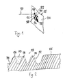
- Fig. 1 illustrates a method of providing a rubber article 100 with a digital code pattern 102 in a cured polymer material of the rubber article 100, according to embodiments of the herein disclosed subject matter.
- the rubber optical 100 is a tire, only part of which is shown in Fig. 1 .
- the method comprises generating the digital code pattern 102 in the cured polymer material 104 of the rubber article 100, the digital code pattern 102 comprising a first surface portion 106 and a second surface portion 108 having different optical reflectivity (hereinafter also referred to as "reflectivity" for short). Since the digital code pattern is generated in the cured polymer material, the digital code pattern is a permanent pattern (in contrast to adhesive labels).
- the digital code pattern 102 is an optically readable digital code pattern.
- the digital code pattern 102 comprises a plurality of first surface portions 106 and a plurality of second surface portions 108, as shown in Fig. 1 .
- the digital code pattern 102 is binary code pattern comprising two distinct reflectivities.
- the digital code pattern may also be realized with more than two distinct reflectivities, e.g. three, four or more distinct reflectivities.
- the digital code pattern 102 is a bar code such as a linear (one-dimensional) bar code or a matrix (two-dimensional) bar code (e.g. a QR code).
- other digital code patterns are also possible.
- optical reflectivity includes a reflectivity for at least one of e.g. infrared radiation, visible light, ultraviolet radiation.
- the digital code pattern 102 identifies the rubber article 100, in particular within a fabrication batch of rubber articles.
- a different identification may be provided by the digital code pattern 102, e.g. an identification within a weekly production (e.g. within tires having the same DOT code and/or tires manufactured in a specific curing mold (curing batch)), within a monthly production or within an annual production, etc.
- the digital code pattern individually identifies each rubber product, e.g. within in a batch.
- the digital code pattern identifies the rubber article as belonging to a subset of a batch (e.g. a curing batch).
- the digital code pattern identifies the rubber article as belonging to a subset of a batch wherein the subset has been equipped with specific properties (such as an emergency operation property of a tire which causes small defects in the tire to be repaired automatically by a suitable inner layer in the tire).
- Identification of the rubber article by the digital code pattern 102 is enabled by any process that generates the digital code pattern 102 individually in each individual rubber article 100.
- generating the digital code pattern 102 may comprise reducing the surface area of the first surface portion (e.g. by flattening) and/or increasing the surface area of the second surface portion (e.g. by artificial roughening e.g. by generating a surface structure).
- generating the digital code pattern comprises irradiating the first surface portion and/or the second surface portion with an electromagnetic radiation 110, e.g. a laser beam as shown in Fig. 1 .
- an electromagnetic radiation 110 e.g. a laser beam as shown in Fig. 1 .
- mechanical techniques are used to generate the digital code pattern in the cured polymer material 104.
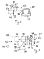
- Fig. 2 shows in a cross-sectional view part of a first surface portion 106 and a second surface portion 108 according to embodiments of the herein disclosed subject matter.
- generating the digital code pattern 102 comprises generating a surface structure 112 in the second surface portion 108.
- the surface structure 112 increases the surface area of the second surface portion 108.
- the surface structure 112 provides a second optical reflectivity which is lower than a first optical reflectivity of the first surface portion 106.
- generating the surface structure 112 comprises selectively removing a part of the cured polymer material 104. The removed part of the cured polymer material 104 is shown with dashed lines at 113 in Fig. 2 .
- the selective removal of the part of the cured polymer is performed with electromagnetic radiation.
- the electromagnetic radiation is a laser radiation, for example a pulsed laser radiation.
- the pulsed laser radiation may have a pulse length of less than 200 nanoseconds, e.g. less than 100 ns or less than 20 ns.
- the laser power and the pulse length may be adjusted to the particular application and in particular to the material from which the rubber article is formed.
- the surface structure 112 comprises a plurality of protrusions 114, as shown in Fig. 2 .
- the first surface portion 106 is generally flat, without surface structure, as shown in Fig. 2 .
- any real material and hence also the cured polymer material 104 has a certain surface roughness Ra.
- a surface structure as referred to herein has dimensions which are larger (according to an embodiment at least by a factor of two) than the mean surface roughness Ra of the rubber article.
- the mean surface roughness Ra of the cured polymer material is below 4 micrometers (Ra ⁇ 4 ⁇ m).
- the mean surface roughness Ra of the cured polymer material is below 1 micrometer (Ra ⁇ 1 ⁇ m), or below 0.5 micrometers (Ra ⁇ 0.5 ⁇ m).
- generating the surface structure 112 does not result in a roughening of the surface and hence the cured polymer material which forms the surface structure 112 has a surface roughness Ra which is equal to or even lower than the surface roughness Ra of the cured polymer material 104 before generating the surface structure.
- the cured polymer material which forms the surface structure has a mean roughness Ra of 4 micrometers or less (Ra ⁇ 4 ⁇ m), e.g. 1 micrometer (Ra ⁇ 1 ⁇ m), or below 0.5 micrometers (Ra ⁇ 0.5 ⁇ m).
- the surface structure 112 comprises a plurality of protrusions 114, as shown in Fig. 2 .
- the protrusions 114 may be generated by selectively removing cured polymer material 104 in the vicinity of the region of the cured polymer where the protrusion is to be established.
- the method of generating a digital code pattern comprises generating an (spatial) intensity pattern of varying intensity of the electromagnetic radiation on the second surface portion to perform the selective removal of cured polymer in high intensity regions of the intensity pattern.
- Fig. 3 shows an intensity pattern 116 on a second surface portion 108 according to embodiments of the herein disclosed subject matter.
- the intensity pattern 116 leads to a selective removal of cured polymer material in regions of high irradiation intensity, thereby generating a surface structure 112 according to embodiments of the herein disclosed subject matter.
- the intensity pattern 116 shown in Fig. 3 is generated by moving an electromagnetic radiation beam along a path on the second surface portion 108.
- the intensity pattern may be an accumulated intensity pattern which shows the intensity accumulated during generation of the surface structure 112.
- the path of the electromagnetic radiation beam corresponds to the desired intensity pattern 116.
- the intensity pattern 116 is generated by any other suitable means, e.g. by a reticle which, when being illuminated with electromagnetic radiation, generates a projection of the intensity pattern 116 on the second surface portion 108.
- the reticle is illuminated with electromagnetic radiation and selectively allows the electromagnetic radiation to pass onto regions of the second surface portion 108 where cured polymer material 104 is to be removed. Further, the reticle blocks the electromagnetic radiation from passing onto regions of the second surface portion 108 in which cured polymer material shall not be removed.
- the intensity pattern is generated by using a higher order mode of a laser which provides the electromagnetic radiation.
- the intensity pattern 116 is generated by interference.
- a diffraction grating is positioned in the radiation path of the electromagnetic radiation, resulting in diffraction of the incoming electromagnetic radiation beam wherein the diffracted beam produces the intensity pattern 116 on the second surface portion.
- the intensity pattern may be a line pattern, as shown in Fig. 3 , or may be e.g. a point pattern.
- the intensity pattern 116 comprises a first set of parallel lines 118 and a second set of parallel lines 120 wherein a line 118 of the first set crosses at least one line 120 of the second set.
- the first set of lines and the second set of lines may define an angle of 90 degrees therebetween, as shown in Fig. 3 , or, in another embodiment may define an angle different from 90 degrees therebetween.
- the intensity pattern comprises three or more sets of parallel lines (not shown in Fig. 3 ) positioned at angles with respect to each other, e.g. for generating an intensity pattern that has hexagonal portions.
- the intensity pattern comprises a single set of parallel lines.
- a protrusion 114 is generated by selectively removing cured polymer material 104 about the region, where the protrusion is to be generated.
- the intensity pattern is generated by moving the electromagnetic radiation beam along the path only once.
- the intensity pattern (e.g. the intensity pattern shown in Fig. 3 ) is generated by moving the electromagnetic radiation beam two times or more often along the path.
- the contour of the second surface portions is traced at least once, e.g. 3 times.
- the pulse overlap of subsequent pulses may be in a range between 50 % and 90 %, e.g. between 70 and 80 %, e.g. 76 %.
- An exemplary 1/e 2 beam diameter of the radiation beam may be between 130 and 180 micrometers, e.g. 150 micrometers.
- the distance between the parallel lines may be smaller than the 1/e 2 beam diameter and may be between 70 and 150 micrometers, e.g. 100 micrometers for a 150 micrometer 1/e 2 beam diameter. In connection with a Gaussian beam profile this may lead to rounded protrusions 114.
- the maximum depth in the surface structure may be between 70 micrometers and 500 micrometers, e.g. 100 micrometers.
- Exemplary laser parameters Ytterbium pulsed fiber laser, central emission wavelength approx. 1064 nm
- kHz kiloHerz
- the surface structure 112 comprises a plurality of holes.
- a hole is formed by removal of cured polymer material at a point.
- the plurality of holes is generated by an intensity pattern having one or more individual spots.
- Fig. 4 shows an (spatial) intensity pattern 122 on a second surface portion 108 according to embodiments of the herein disclosed subject matter.
- the intensity pattern 122 leads to a selective removal of cured polymer material in regions of high irradiation intensity, thereby generating a surface structure 112 according to embodiments of the herein disclosed subject matter.
- the intensity pattern 122 comprises a plurality of spots some of which are indicated at 124 in Fig. 4 .
- Each spot 124 generates a hole 126 by selective removal of the cured polymer material 104 in the region of the spot 124.
- other intensity patterns may be used to generate the surface structure in the second surface portions.
- other surface structures may be generated in the second surface portion in order to provide a second reflectivity which is lower than the first reflectivity of the first surface portion.
- the entire intensity pattern on the second surface portion or, according to another embodiment, an all second surface portions of the digital code pattern is generated at the same time (simultaneous exposure mode), e.g. by using a suitable reticle.
- the intensity pattern on a second surface portion is generated over a certain time period (scanning mode), e.g. by moving a beam of electromagnetic radiation over the second surface portion.
- an (spatial) intensity pattern or the generation of an intensity pattern may be configured to include features of two or more embodiments as disclosed herein.
- the intensity pattern is generated by moving an electromagnetic radiation beam along a path on the second surface portion, wherein the electromagnetic radiation beam itself has a structured intensity distribution which is e.g. generated by interference or a higher order mode of a laser beam. This may lead to an intensity pattern on the second surface which includes spatial intensity variations on different length scales.
- the intensity pattern may include spatial intensity variations on different length scales. According to an embodiment, this may also be generated by a respective movement of an electromagnetic radiation beam or, advantageously by combining different embodiments of intensity pattern generation, e.g. by moving an electromagnetic radiation beam with structured intensity distribution over the second surface, as described above.
- the surface structure comprises two or more sub structures of different length scale. In accordance with an embodiment, this may provide a low reflectivity as well as a good cleaning behavior of the second surface portion.
- the combinations of embodiments described above may be used to generate an intensity pattern which on the longer length scale has lines (e.g. with a sub structure having lines and/or points) or, in another embodiment, may be used to generate an intensity pattern which on the longer length scale has points (e.g. with a sub structure having lines and/or points).
- the Rayleigh length of the electromagnetical radiation is larger than 1.5 millimeters, e.g. larger than 2 millimeters or larger than 4 millimeters.
- a large Rayleigh length which provides a large depth of focus may be advantageous for generating digital code patterns on curved surfaces, e.g. on tires.
- providing the first surface portion 106 includes manufacturing the cured polymer material 104 with a predetermined surface roughness Ra at least in a region which comprises the first surface portion 106; and maintaining the predetermined surface roughness Ra in the first surface portion 106 during generating the surface structure 112 in the second surface portion 108.
- the first surface portion 106 may remain unchanged in the generation of the digital code pattern 102.
- the reflectivity of the first surface portions 106 may be adjusted.
- generating the digital code pattern 102 comprises flattening the first surface portions 106, the flattened first surface portions 106 providing a first optical reflectivity which is higher than a second optical reflectivity of the second surface portions 108.
- providing the first surface portion 106 includes reducing the surface roughness Ra in the first surface portion 106 of the cured polymer material 104 as manufactured.
- Fig. 5 illustrates a further process for generating a digital code pattern 102 according to embodiments of the herein disclosed subject matter.
- the region, in which the digital code pattern 102 is to be established is completely provided with a surface structure 112 as disclosed herein, i.e in the region of the first surface portion 106 (shown in dashed line in Fig. 5 ) as well as in the region of the second surface portion 108.
- the first surface portion 106 may be generated by flattening the surface structure 112 in the region of the first surface portion 106, e.g. by exposing the region of the first surface portion 106 to electromagnetic radiation 110.
- the surface structure 112 is maintained, thereby resulting in the second surface portions 108 having lower optical reflectivity than the first surface portions 106.
- Fig. 6 shows a rubber article marking device according to embodiments of the herein disclosed subject matter.
- the rubber article marking device 150 comprises a holder 151 for receiving a rubber article 100. Further, the rubber article marking device 150 comprises a radiation source 152 for providing electromagnetic radiation 110 and a controller 154 for controlling the radiation source 152 so as to perform a method of providing a rubber article with a digital code pattern 102 according one or more embodiments of the herein disclosed subject matter.
- the rubber article marking device 150 comprises at least one actuator (e.g. a scan unit, not shown in Fig. 6 ) which is configured for moving the electromagnetic radiation beam 110 with respect to the rubber article 100 in the holder 151 so as to generate the digital code pattern 102 on the rubber article 100.
- the actuator is controlled by the controller 154.
- the controller 154 is configured for controlling the operation of the radiation source, e.g. for switching on and off the electromagnetic radiation beam 110.
- the controller 154 comprises a data processor device 155, e.g. computer, for executing computer program which is configured for, when executed on the data processor device 155, controlling the method according to one or more embodiments as disclosed herein.
- the computer program is included in a software update or a firmware update of the controller 154 so that existing tools can be updated so as to provide functionality according to embodiments of the herein disclosed subject matter.
- the controller 154 is configured for exchanging signals 153 with (e.g. providing control signals to) at least one entity to be controlled by the controller 154.
- entities may include e.g. the radiation source 152, conveyor devices (not shown in Fig. 6 ), etc.
- the method of providing a rubber product with a digital code pattern comprises adjusting the focus position of the radiation source 152 which generates the electromagnetic radiation 110 during generating the digital code pattern 102.
- the light source 152 may comprise a focus position adjustment device 157. Adjusting the focus position during the generation of the code pattern may be advantageous e.g. if the digital code pattern is generated on a curved surface of the cured polymer material. Adjusting the focus position may further be advantageous if the radiation source is configured for moving the electromagnetic radiation beam 110 over the cured polymer material by pivoting the electromagnetic radiation beam, resulting in the electromagnetic radiation beam impinging inclined on the cured polymer material.
- the adjustment of the focus position may be performed according to a predefined control sequence which may be adapted to the particular rubber product and which may be stored in a memory 156 of the controller 154.
- a sensor 158 for determining a position of the rubber article 100, e.g. with respect to the focusing lens.
- the sensor includes a distance sensor for determining the position or the rubber article 100.
- the controller 154 is adapted for adjusting the focus position of the radiation source 152 in response to the position of the rubber article 100. Adjustment of the focus position may be performed e.g. by moving one or more lenses (e.g. of the focusing lens) of the radiation source or, according to another embodiment, by expanding the beam impinging on the focusing lens of the radiation source 152, just to name some examples.
- Adjustment of the focus position may be performed so as to move the focus position onto the surface of the rubber article 100.
- Fig. 7 shows part of a further rubber article marking device 250 according to embodiments of the herein disclosed subject matter.
- the rubber article marking device 250 comprises a radiation source 152 which has a beam splitter 163 for splitting a primary radiation beam 164 into two secondary beams, a first secondary beam 165 and a second secondary beam 166.
- the radiation source 152 includes a suitable source 167, e.g. a laser, for providing the primary radiation beam 164, as shown in Fig. 7 .
- the radiation source 152 comprises a phase adjustment device 168 for changing the phase of the first secondary beam 165 with respect to the phase of the second secondary beam 166 and providing a phase-shifted first secondary beam 170.
- the phase adjustment device 168 comprises mirrors 172, 174, 176, of which at least some (e.g. two mirrors 172, 174) may be moveable (indicated at 177) in order to provide the phase adjustment device 168 with the capability to change the phase shift.
- the radiation source 152 further comprises two scan units 178, 180 of which a first scan unit 178 is configured for projecting the phase shifted first secondary beam 170 onto the rubber article 100 in a first spot 182 and a second scan unit 180 is configured for projecting the second secondary beam 166 onto the rubber article 100 in a second spot 184 overlapping the first spot 182.
- the two beams 166, 170 projected onto the article 100 overlap in time and space and therefore generate an interference pattern in the overlap of both spots 182, 184.
- the phase adjustment device 168 may be integrated into the respective scan unit 178.
- the interference pattern may be used to selectively remove cured polymer material from the rubber article 100 in order to generate a digital code pattern.
- the controller 154 is configured for operating the scan units 178, 180 so as to provide a desired intensity pattern on a second surface portion by moving the overlapping spots 182, 184 together over the second surface portion.
- the controller 154 may be configured so as to move the overlapping spots 182, 184 together from one (second) surface portion 108 to another (second) surface portion 108. It is noted that the two overlapping beams 166, 170 together a form a "electromagnetic radiation 110" as referred to herein in other embodiments.
- the rubber article marking device may comprise a reticle (not shown in Fig. 7 ) defining the size of the respective surface portion (first surface portion or second surface portion) to which electromagnetic radiation shall be applied.
- a reticle (not shown in Fig. 7 ) defining the size of the respective surface portion (first surface portion or second surface portion) to which electromagnetic radiation shall be applied.
- the intensity pattern such as an interference pattern
- the reticle provides sharply defined edges of the respective surface portion.
- the reticle is configured to provide the respective surface portion with a variable area, e.g. by movable parts which laterally define a passage which in turn defines the respective surface portion.
- the size of the respective surface portion is variable which may be necessary in some digital code patterns, e.g. in a QR code where the size of the first and second surface portions depends on the amount of information coded with the QR code.
- Fig. 8 shows a device for identifying a rubber article and illustrates a method of identifying a rubber article according to embodiments of the herein disclosed subject matter.
- a device 160 for identifying a rubber article 100 (e.g. in the form of a tire) according to embodiments of the herein disclosed subject matter.
- the device 160 is configured for reading the digital code pattern 102 from a polymer 104 surface of the rubber article 100.
- the device 160 may comprise a camera configured for acquiring a picture of the digital code pattern 102.
- the device 160 comprises a controller 162 which is configured for decoding the digital code pattern 102 and providing in response hereto a digital representation of the information stored in the digital code pattern 102.
- the digital code pattern may be a graphical representation of identification information (e.g.
- the device 160 has access to a database which has stored therein in the identification information represented by the digital code pattern and the specific information on the rubber article. This allows the device 160 to retrieve the specific information on the rubber article from the database upon extracting (decoding) the identification information from the acquired a digital code pattern.
- the device 160 may be a stationary device e.g. in a tire manufacturing facility or may be e.g. portable device, e.g. a smart phone, which allows a user of the rubber article, e.g. a tire, to retrieve information on the rubber article in a familiar and pleasant way.
- portable device e.g. a smart phone
- Identifying a rubber article such as a tire is advantageous in any application where identification tracking of a tire is helpful or even mandatory.
- Generating the digital code pattern in the cured polymer allows providing the rubber article with the digital code pattern independently from manufacturing of the rubber article and without requiring adhesive labels or the like.
- any suitable entity e.g. components, units and devices
- the controller are at least in part provided in the form of respective computer programs which enable a processor device to provide the functionality of the respective entities as disclosed herein.
- any suitable entity disclosed herein may be provided in hardware.
- some entities may be provided in software while other entities are provided in hardware.
- any entity disclosed herein e.g. components, units and devices such as the controller, the radiation source, the scan unit, the phase shift unit, etc
- any entity disclosed herein are not limited to a dedicated entity as described in some embodiments. Rather, the herein disclosed subject matter may be implemented in various ways and with various granularity on device level or, where applicable, on software module level while still providing the specified functionality.
- an entity (part, portion, surface, component, unit, structure or device) is configured for providing two or more functions as disclosed herein.
- two or more entities e.g. part, portion, surface, component, unit, structure or device are configured for providing together a function as disclosed herein.
- the controller comprises a processor device including at least one processor for carrying out at least one computer program corresponding to a respective software module.
Priority Applications (4)
| Application Number | Priority Date | Filing Date | Title |
|---|---|---|---|
| EP17188416.6A EP3284586B1 (fr) | 2014-02-10 | 2014-02-10 | Articles en caoutchouc avec codage numérique et identification du codage numérique |
| EP14154445.2A EP2905125B1 (fr) | 2014-02-10 | 2014-02-10 | Codage numérique d'articles en caoutchouc |
| US15/117,703 US20170011666A1 (en) | 2014-02-10 | 2015-02-09 | Digital coding of rubber articles |
| PCT/EP2015/052662 WO2015118155A1 (fr) | 2014-02-10 | 2015-02-09 | Codage numérique d'articles en caoutchouc |
Applications Claiming Priority (1)
| Application Number | Priority Date | Filing Date | Title |
|---|---|---|---|
| EP14154445.2A EP2905125B1 (fr) | 2014-02-10 | 2014-02-10 | Codage numérique d'articles en caoutchouc |
Related Child Applications (1)
| Application Number | Title | Priority Date | Filing Date |
|---|---|---|---|
| EP17188416.6A Division EP3284586B1 (fr) | 2014-02-10 | 2014-02-10 | Articles en caoutchouc avec codage numérique et identification du codage numérique |
Publications (2)
| Publication Number | Publication Date |
|---|---|
| EP2905125A1 true EP2905125A1 (fr) | 2015-08-12 |
| EP2905125B1 EP2905125B1 (fr) | 2017-08-30 |
Family
ID=50070420
Family Applications (2)
| Application Number | Title | Priority Date | Filing Date |
|---|---|---|---|
| EP14154445.2A Active EP2905125B1 (fr) | 2014-02-10 | 2014-02-10 | Codage numérique d'articles en caoutchouc |
| EP17188416.6A Active EP3284586B1 (fr) | 2014-02-10 | 2014-02-10 | Articles en caoutchouc avec codage numérique et identification du codage numérique |
Family Applications After (1)
| Application Number | Title | Priority Date | Filing Date |
|---|---|---|---|
| EP17188416.6A Active EP3284586B1 (fr) | 2014-02-10 | 2014-02-10 | Articles en caoutchouc avec codage numérique et identification du codage numérique |
Country Status (3)
| Country | Link |
|---|---|
| US (1) | US20170011666A1 (fr) |
| EP (2) | EP2905125B1 (fr) |
| WO (1) | WO2015118155A1 (fr) |
Cited By (16)
| Publication number | Priority date | Publication date | Assignee | Title |
|---|---|---|---|---|
| EP3135424A1 (fr) * | 2015-08-28 | 2017-03-01 | Continental Reifen Deutschland GmbH | Procédé pour l'insertion de structures dans la surface d'un pneu de véhicule |
| EP3147114A1 (fr) | 2015-09-24 | 2017-03-29 | 4JET Technologies GmbH | Dispositif de traitement de pneus par usinage laser |
| CN106863768A (zh) * | 2017-01-20 | 2017-06-20 | 安徽佳通乘用子午线轮胎有限公司 | 一种轮胎花纹雕刻台架 |
| EP3219478A1 (fr) | 2016-03-18 | 2017-09-20 | 4JET Technologies GmbH | Dispositif de marquage de pneu, procédé pour faire fonctionner un dispositif de marquage de pneu et dispositif de commande pour dispositif de marquage de pneu |
| EP3235633A1 (fr) * | 2016-04-19 | 2017-10-25 | Continental Reifen Deutschland GmbH | Procédé de fabrication d'un pneumatique de véhicule |
| EP3238928A1 (fr) | 2016-04-28 | 2017-11-01 | 4JET Technologies GmbH | Synchronisation d'informations sur un pneu |
| IT201600072749A1 (it) * | 2016-07-13 | 2018-01-13 | Snap On Equipment S R L A Unico Socio | Metodo ed apparato per identificare univocamente gli pneumatici di ruote di veicoli nell'ambito di processi di manutenzione di ruote di veicoli |
| FR3054975A1 (fr) * | 2014-04-30 | 2018-02-16 | Compagnie Generale Des Etablissements Michelin | Pneumatique comportant un symbole matriciel a fort contraste sur le flanc |
| WO2018065135A1 (fr) * | 2016-10-07 | 2018-04-12 | Continental Reifen Deutschland Gmbh | Procédé de fabrication d'un pneu de véhicule |
| EP3308978A1 (fr) * | 2016-10-17 | 2018-04-18 | Continental Reifen Deutschland GmbH | Pneumatiques de véhicule |
| WO2018180497A1 (fr) * | 2017-03-28 | 2018-10-04 | 横浜ゴム株式会社 | Pneu, moule de pneu, procédé de test de marque gravée de code bidimensionnel et procédé de fabrication de pneu |
| CN110382261A (zh) * | 2017-03-06 | 2019-10-25 | 米其林企业总公司 | 在侧壁上设置有纹理部的轮胎 |
| EP3297816B1 (fr) | 2015-05-21 | 2020-10-14 | 4JET Technologies GmbH | Motif d'évidements dans un article en caoutchouc |
| US11162873B2 (en) | 2016-08-10 | 2021-11-02 | 4Jet Technologies Gmbh | Tire processing method |
| CN113993694A (zh) * | 2019-06-13 | 2022-01-28 | 米其林集团总公司 | 在轮胎上沉积着色层的方法 |
| WO2023031930A1 (fr) * | 2021-09-03 | 2023-03-09 | Security Matters Ltd. | Marquage xrf de caoutchouc naturel |
Families Citing this family (11)
| Publication number | Priority date | Publication date | Assignee | Title |
|---|---|---|---|---|
| RU2648423C2 (ru) * | 2016-06-06 | 2018-03-26 | Федеральное государственное бюджетное образовательное учреждение высшего образования "Волгоградский государственный технический университет" (ВолгГТУ) | Способ маркировки и идентификации изделий из резины |
| CN110494276B (zh) * | 2017-04-20 | 2021-10-01 | 横滨橡胶株式会社 | 充气轮胎的制造方法、轮胎模具和充气轮胎 |
| DE202017006817U1 (de) | 2017-05-10 | 2018-07-09 | Kba-Metronic Gmbh | Vorrichtung zum Markieren von Objekten und Trägerkörper mit einer Mehrzahl von Kennzeichnungskörpern |
| CN111108007B (zh) * | 2017-10-04 | 2021-01-08 | 横滨橡胶株式会社 | 充气轮胎 |
| JP6465263B1 (ja) * | 2017-10-04 | 2019-02-06 | 横浜ゴム株式会社 | 空気入りタイヤ |
| WO2019124253A1 (fr) * | 2017-12-20 | 2019-06-27 | 横浜ゴム株式会社 | Bandage pneumatique |
| JP7119766B2 (ja) * | 2018-08-23 | 2022-08-17 | 住友ゴム工業株式会社 | タイヤ |
| JP7279409B2 (ja) * | 2019-02-27 | 2023-05-23 | 横浜ゴム株式会社 | 空気入りタイヤ |
| US11614380B2 (en) | 2019-07-02 | 2023-03-28 | Hunter Engineering Company | System and method for acquisition of tire sidewall data from a moving vehicle |
| DE102020125679A1 (de) | 2020-10-01 | 2022-04-07 | Homag Gmbh | Vorrichtung und Verfahren zur Bearbeitung, insbesondere zur Veredelung, von Oberflächen |
| CN114684490B (zh) * | 2022-03-29 | 2023-05-09 | 安徽邮谷快递智能科技有限公司 | 基于溯源技术的快递物流共配专用箱及快递物流方法 |
Citations (13)
| Publication number | Priority date | Publication date | Assignee | Title |
|---|---|---|---|---|
| EP0689948A2 (fr) * | 1994-06-28 | 1996-01-03 | Uniroyal Englebert Reifen GmbH | Application d'un caractère dans une surface visible d'un bandage pneumatique |
| EP0770448A1 (fr) * | 1995-10-27 | 1997-05-02 | E.I. Du Pont De Nemours And Company | Procédé et appareil pour la découpe au laser de matériaux |
| JP2000084681A (ja) * | 1998-09-07 | 2000-03-28 | Bridgestone Corp | タイヤマーキング装置及びタイヤマーキング方法並びにタイヤ |
| US6149060A (en) * | 1996-03-27 | 2000-11-21 | The Goodyear Tire & Rubber Company | Means and method of identifying objects using a zero contrast sensor |
| US6169266B1 (en) * | 1998-03-25 | 2001-01-02 | Xirom, Inc. | Etching of multi-layered coated surfaces to add graphic and text elements to an article |
| DE10128609A1 (de) * | 2001-06-13 | 2003-01-09 | Esab Cutting Systems Gmbh | Anordnung zur Verstellung des Fokusradius und der Rayleighlänge für die Laserstrahlbearbeitung, insbesonere in einer Laserschneidmaschine |
| EP1437672A2 (fr) * | 2003-01-10 | 2004-07-14 | The Yokohama Rubber Co., Ltd. | Système de marquage de pneumatique |
| US20040155017A1 (en) * | 2003-01-29 | 2004-08-12 | Hunt Alan J. | Method for forming nanoscale features |
| JP2004345310A (ja) * | 2003-05-26 | 2004-12-09 | Yokohama Rubber Co Ltd:The | タイヤ識別標識刻印方法 |
| WO2005000714A1 (fr) * | 2003-06-23 | 2005-01-06 | Bridgestone/Firestone North American Tire, Llc | Procede et systeme pour marquer des pneus |
| WO2011107602A2 (fr) * | 2010-03-05 | 2011-09-09 | Micronic Mydata AB | Procédés et dispositif de traitement au laser |
| US20130082037A1 (en) * | 2009-12-22 | 2013-04-04 | François Champonnois | Method of ablating a three-dimensional surface using a laser ablation device and through the use of a calibration step; device for implementing such a method |
| WO2013095479A1 (fr) * | 2011-12-22 | 2013-06-27 | Michelin Recherche Et Technique, S.A. | Ablation laser par positionnement direct |
Family Cites Families (3)
| Publication number | Priority date | Publication date | Assignee | Title |
|---|---|---|---|---|
| DE19928863A1 (de) | 1999-06-24 | 2001-01-04 | Continental Ag | Fahrzeugreifen |
| FR2892336B1 (fr) | 2005-10-21 | 2009-10-09 | Michelin Soc Tech | Marquage offrant une meilleure visibilite et procede de marquage. |
| FR2950566B1 (fr) | 2009-09-28 | 2011-08-26 | Michelin Soc Tech | Motif de pneumatique a fort contraste et procede d'obtention |
-
2014
- 2014-02-10 EP EP14154445.2A patent/EP2905125B1/fr active Active
- 2014-02-10 EP EP17188416.6A patent/EP3284586B1/fr active Active
-
2015
- 2015-02-09 US US15/117,703 patent/US20170011666A1/en not_active Abandoned
- 2015-02-09 WO PCT/EP2015/052662 patent/WO2015118155A1/fr active Application Filing
Patent Citations (13)
| Publication number | Priority date | Publication date | Assignee | Title |
|---|---|---|---|---|
| EP0689948A2 (fr) * | 1994-06-28 | 1996-01-03 | Uniroyal Englebert Reifen GmbH | Application d'un caractère dans une surface visible d'un bandage pneumatique |
| EP0770448A1 (fr) * | 1995-10-27 | 1997-05-02 | E.I. Du Pont De Nemours And Company | Procédé et appareil pour la découpe au laser de matériaux |
| US6149060A (en) * | 1996-03-27 | 2000-11-21 | The Goodyear Tire & Rubber Company | Means and method of identifying objects using a zero contrast sensor |
| US6169266B1 (en) * | 1998-03-25 | 2001-01-02 | Xirom, Inc. | Etching of multi-layered coated surfaces to add graphic and text elements to an article |
| JP2000084681A (ja) * | 1998-09-07 | 2000-03-28 | Bridgestone Corp | タイヤマーキング装置及びタイヤマーキング方法並びにタイヤ |
| DE10128609A1 (de) * | 2001-06-13 | 2003-01-09 | Esab Cutting Systems Gmbh | Anordnung zur Verstellung des Fokusradius und der Rayleighlänge für die Laserstrahlbearbeitung, insbesonere in einer Laserschneidmaschine |
| EP1437672A2 (fr) * | 2003-01-10 | 2004-07-14 | The Yokohama Rubber Co., Ltd. | Système de marquage de pneumatique |
| US20040155017A1 (en) * | 2003-01-29 | 2004-08-12 | Hunt Alan J. | Method for forming nanoscale features |
| JP2004345310A (ja) * | 2003-05-26 | 2004-12-09 | Yokohama Rubber Co Ltd:The | タイヤ識別標識刻印方法 |
| WO2005000714A1 (fr) * | 2003-06-23 | 2005-01-06 | Bridgestone/Firestone North American Tire, Llc | Procede et systeme pour marquer des pneus |
| US20130082037A1 (en) * | 2009-12-22 | 2013-04-04 | François Champonnois | Method of ablating a three-dimensional surface using a laser ablation device and through the use of a calibration step; device for implementing such a method |
| WO2011107602A2 (fr) * | 2010-03-05 | 2011-09-09 | Micronic Mydata AB | Procédés et dispositif de traitement au laser |
| WO2013095479A1 (fr) * | 2011-12-22 | 2013-06-27 | Michelin Recherche Et Technique, S.A. | Ablation laser par positionnement direct |
Cited By (30)
| Publication number | Priority date | Publication date | Assignee | Title |
|---|---|---|---|---|
| FR3054975A1 (fr) * | 2014-04-30 | 2018-02-16 | Compagnie Generale Des Etablissements Michelin | Pneumatique comportant un symbole matriciel a fort contraste sur le flanc |
| EP3137318B1 (fr) * | 2014-04-30 | 2020-07-29 | Compagnie Générale des Etablissements Michelin | Pneumatique comportant un symbole matriciel a fort contraste sur le flanc |
| EP3297816B1 (fr) | 2015-05-21 | 2020-10-14 | 4JET Technologies GmbH | Motif d'évidements dans un article en caoutchouc |
| EP3135424A1 (fr) * | 2015-08-28 | 2017-03-01 | Continental Reifen Deutschland GmbH | Procédé pour l'insertion de structures dans la surface d'un pneu de véhicule |
| EP3147114A1 (fr) | 2015-09-24 | 2017-03-29 | 4JET Technologies GmbH | Dispositif de traitement de pneus par usinage laser |
| WO2017051022A1 (fr) | 2015-09-24 | 2017-03-30 | 4Jet Technologies Gmbh | Procédé et appareil de traitement de pneu par un faisceau laser |
| EP3219478A1 (fr) | 2016-03-18 | 2017-09-20 | 4JET Technologies GmbH | Dispositif de marquage de pneu, procédé pour faire fonctionner un dispositif de marquage de pneu et dispositif de commande pour dispositif de marquage de pneu |
| EP3235633A1 (fr) * | 2016-04-19 | 2017-10-25 | Continental Reifen Deutschland GmbH | Procédé de fabrication d'un pneumatique de véhicule |
| WO2017186879A1 (fr) | 2016-04-28 | 2017-11-02 | 4Jet Technologies Gmbh | Synchronisation d'informations sur un pneu |
| EP3238928A1 (fr) | 2016-04-28 | 2017-11-01 | 4JET Technologies GmbH | Synchronisation d'informations sur un pneu |
| CN107618320B (zh) * | 2016-07-13 | 2021-03-19 | 斯耐普昂仪器有限公司 | 车轮维护过程一部分、用于唯一识别轮胎的方法和设备 |
| US20180015795A1 (en) * | 2016-07-13 | 2018-01-18 | Snap-On Equipment S.R.L. | Method and apparatus for uniquely identifying tyres for wheels of vehicles as part of vehicle wheel maintenance processes |
| IT201600072749A1 (it) * | 2016-07-13 | 2018-01-13 | Snap On Equipment S R L A Unico Socio | Metodo ed apparato per identificare univocamente gli pneumatici di ruote di veicoli nell'ambito di processi di manutenzione di ruote di veicoli |
| US10654323B2 (en) | 2016-07-13 | 2020-05-19 | Snap-On Equipment S.R.L. | Method and apparatus for uniquely identifying tyres for wheels of vehicles as part of vehicle wheel maintenance processes |
| EP3269569A1 (fr) | 2016-07-13 | 2018-01-17 | Snap-on Equipment S.r.l. | Procede et appareil pour l'identification des pneumatiques de véhicule dans le cadre d'une procedure de maintenance des roues |
| CN107618320A (zh) * | 2016-07-13 | 2018-01-23 | 斯耐普昂仪器有限公司 | 车轮维护过程一部分、用于唯一识别轮胎的方法和设备 |
| US11162873B2 (en) | 2016-08-10 | 2021-11-02 | 4Jet Technologies Gmbh | Tire processing method |
| WO2018065135A1 (fr) * | 2016-10-07 | 2018-04-12 | Continental Reifen Deutschland Gmbh | Procédé de fabrication d'un pneu de véhicule |
| EP3308978A1 (fr) * | 2016-10-17 | 2018-04-18 | Continental Reifen Deutschland GmbH | Pneumatiques de véhicule |
| CN106863768A (zh) * | 2017-01-20 | 2017-06-20 | 安徽佳通乘用子午线轮胎有限公司 | 一种轮胎花纹雕刻台架 |
| CN110382261A (zh) * | 2017-03-06 | 2019-10-25 | 米其林企业总公司 | 在侧壁上设置有纹理部的轮胎 |
| US11364749B2 (en) | 2017-03-28 | 2022-06-21 | The Yokohama Rubber Co., Ltd. | Pneumatic tire, pneumatic-tire mold, two-dimensional-code engraved-mark testing method, and pneumatic-tire manufacturing method |
| CN110337375A (zh) * | 2017-03-28 | 2019-10-15 | 横滨橡胶株式会社 | 充气轮胎、充气轮胎的模具、二维码的刻印的检查方法、以及制造充气轮胎的方法 |
| EP3603997A4 (fr) * | 2017-03-28 | 2020-12-02 | The Yokohama Rubber Co., Ltd. | Pneu, moule de pneu, procédé de test de marque gravée de code bidimensionnel et procédé de fabrication de pneu |
| CN110337375B (zh) * | 2017-03-28 | 2020-07-07 | 横滨橡胶株式会社 | 充气轮胎、充气轮胎的模具、二维码的刻印的检查方法、以及制造充气轮胎的方法 |
| JPWO2018180497A1 (ja) * | 2017-03-28 | 2019-04-04 | 横浜ゴム株式会社 | 空気入りタイヤ、空気入りタイヤの金型、二次元コードの刻印の検査方法、及び空気入りタイヤを製造する方法 |
| WO2018180497A1 (fr) * | 2017-03-28 | 2018-10-04 | 横浜ゴム株式会社 | Pneu, moule de pneu, procédé de test de marque gravée de code bidimensionnel et procédé de fabrication de pneu |
| CN113993694B (zh) * | 2019-06-13 | 2023-10-24 | 米其林集团总公司 | 在轮胎上沉积着色层的方法 |
| CN113993694A (zh) * | 2019-06-13 | 2022-01-28 | 米其林集团总公司 | 在轮胎上沉积着色层的方法 |
| WO2023031930A1 (fr) * | 2021-09-03 | 2023-03-09 | Security Matters Ltd. | Marquage xrf de caoutchouc naturel |
Also Published As
| Publication number | Publication date |
|---|---|
| EP3284586A1 (fr) | 2018-02-21 |
| US20170011666A1 (en) | 2017-01-12 |
| EP2905125B1 (fr) | 2017-08-30 |
| EP3284586B1 (fr) | 2020-04-08 |
| WO2015118155A1 (fr) | 2015-08-13 |
Similar Documents
| Publication | Publication Date | Title |
|---|---|---|
| EP2905125A1 (fr) | Codage numérique d'articles en caoutchouc | |
| EP2977934A1 (fr) | Codage numérique d'articles en caoutchouc | |
| US20210016496A1 (en) | High-throughput 3d printing of customized aspheric imaging lenses | |
| Naessens et al. | Flexible fabrication of microlenses in polymer layers with excimer laser ablation | |
| CN110573291B (zh) | 通过激光光刻制造3d结构的方法及相应的计算机程序产品 | |
| KR102562242B1 (ko) | 고무 물품 내의 리세스 패턴 | |
| EP3757628B1 (fr) | Plaque de diffusion | |
| EP3551435B1 (fr) | Machine de stéréolithographie avec groupe optique amélioré | |
| JP2008070556A (ja) | 光学部材の製造方法および光学部材成形用型の製造方法 | |
| DE202014010855U1 (de) | Digitales Codieren von Gummiartikeln | |
| KR101765325B1 (ko) | 레이저 양각 패턴을 이용한 몰드 제조방법 | |
| US8585390B2 (en) | Mold making system and mold making method | |
| DE202014011007U1 (de) | Digitales Codieren von Gummiartikeln | |
| JPH07151910A (ja) | 回折格子露光方法 | |
| EP4155820A1 (fr) | Lithographie multiphotonique contrôlée et vérifiée en temps réel | |
| KR102005632B1 (ko) | 파면 제어기를 이용한 고속 3차원 광조형 방법 및 장치 | |
| KR102497174B1 (ko) | 이광자 스테레오리소그래피의 이중패터닝 방법 및 장치 | |
| EP4335630A1 (fr) | Procédé de formation de motifs sur un masque, procédé de production d'un insert ou d'un moule, et article optique à microstructures de surface | |
| Kim et al. | Exposure time variation method using DMD for microstereolithography | |
| KR100573927B1 (ko) | 미세한 3차원 자유곡면 형성방법 | |
| EP1218777A1 (fr) | Mosaique de microlentilles presentant un rendement focal eleve | |
| Caspary et al. | Focus-based automated alignment for laser direct writing | |
| CN118056205A (zh) | 用于在部件上或部件中形成图像的方法和设备 | |
| KR20210122103A (ko) | 압출 제어를 위한 프레임 경화 이미징 해상도를 개선하기 위한 방법 및 장치 | |
| Pedder et al. | Excimer laser micromachining of polymers using half-tone masks: mask design and process optimization |
Legal Events
| Date | Code | Title | Description |
|---|---|---|---|
| REG | Reference to a national code |
Ref country code: DE Ref legal event code: R138 Ref document number: 202014010855 Country of ref document: DE Free format text: GERMAN DOCUMENT NUMBER IS 602014013683 |
|
| PUAI | Public reference made under article 153(3) epc to a published international application that has entered the european phase |
Free format text: ORIGINAL CODE: 0009012 |
|
| AK | Designated contracting states |
Kind code of ref document: A1 Designated state(s): AL AT BE BG CH CY CZ DE DK EE ES FI FR GB GR HR HU IE IS IT LI LT LU LV MC MK MT NL NO PL PT RO RS SE SI SK SM TR |
|
| AX | Request for extension of the european patent |
Extension state: BA ME |
|
| 17P | Request for examination filed |
Effective date: 20160118 |
|
| RBV | Designated contracting states (corrected) |
Designated state(s): AL AT BE BG CH CY CZ DE DK EE ES FI FR GB GR HR HU IE IS IT LI LT LU LV MC MK MT NL NO PL PT RO RS SE SI SK SM TR |
|
| REG | Reference to a national code |
Ref country code: DE Ref legal event code: R079 Ref document number: 602014013683 Country of ref document: DE Free format text: PREVIOUS MAIN CLASS: B29D0030720000 Ipc: B23K0026360000 |
|
| RIC1 | Information provided on ipc code assigned before grant |
Ipc: B41M 5/24 20060101ALI20170515BHEP Ipc: B29D 30/72 20060101ALI20170515BHEP Ipc: B23K 101/00 20060101ALI20170515BHEP Ipc: B60C 13/00 20060101ALI20170515BHEP Ipc: G09F 3/00 20060101ALI20170515BHEP Ipc: B29C 59/16 20060101ALI20170515BHEP Ipc: B29C 35/08 20060101ALI20170515BHEP Ipc: B23K 26/00 20140101ALI20170515BHEP Ipc: B23K 103/00 20060101ALI20170515BHEP Ipc: B23K 26/067 20060101ALI20170515BHEP Ipc: B29C 33/42 20060101ALI20170515BHEP Ipc: B29L 30/00 20060101ALI20170515BHEP Ipc: B23K 26/36 20140101AFI20170515BHEP Ipc: B23K 26/361 20140101ALI20170515BHEP Ipc: B23K 26/0622 20140101ALI20170515BHEP |
|
| GRAP | Despatch of communication of intention to grant a patent |
Free format text: ORIGINAL CODE: EPIDOSNIGR1 |
|
| GRAS | Grant fee paid |
Free format text: ORIGINAL CODE: EPIDOSNIGR3 |
|
| INTG | Intention to grant announced |
Effective date: 20170627 |
|
| GRAA | (expected) grant |
Free format text: ORIGINAL CODE: 0009210 |
|
| AK | Designated contracting states |
Kind code of ref document: B1 Designated state(s): AL AT BE BG CH CY CZ DE DK EE ES FI FR GB GR HR HU IE IS IT LI LT LU LV MC MK MT NL NO PL PT RO RS SE SI SK SM TR |
|
| REG | Reference to a national code |
Ref country code: GB Ref legal event code: FG4D |
|
| REG | Reference to a national code |
Ref country code: CH Ref legal event code: EP |
|
| REG | Reference to a national code |
Ref country code: AT Ref legal event code: REF Ref document number: 923059 Country of ref document: AT Kind code of ref document: T Effective date: 20170915 |
|
| REG | Reference to a national code |
Ref country code: IE Ref legal event code: FG4D |
|
| REG | Reference to a national code |
Ref country code: DE Ref legal event code: R096 Ref document number: 602014013683 Country of ref document: DE |
|
| REG | Reference to a national code |
Ref country code: NL Ref legal event code: MP Effective date: 20170830 |
|
| REG | Reference to a national code |
Ref country code: LT Ref legal event code: MG4D |
|
| REG | Reference to a national code |
Ref country code: AT Ref legal event code: MK05 Ref document number: 923059 Country of ref document: AT Kind code of ref document: T Effective date: 20170830 |
|
| PG25 | Lapsed in a contracting state [announced via postgrant information from national office to epo] |
Ref country code: SE Free format text: LAPSE BECAUSE OF FAILURE TO SUBMIT A TRANSLATION OF THE DESCRIPTION OR TO PAY THE FEE WITHIN THE PRESCRIBED TIME-LIMIT Effective date: 20170830 Ref country code: LT Free format text: LAPSE BECAUSE OF FAILURE TO SUBMIT A TRANSLATION OF THE DESCRIPTION OR TO PAY THE FEE WITHIN THE PRESCRIBED TIME-LIMIT Effective date: 20170830 Ref country code: FI Free format text: LAPSE BECAUSE OF FAILURE TO SUBMIT A TRANSLATION OF THE DESCRIPTION OR TO PAY THE FEE WITHIN THE PRESCRIBED TIME-LIMIT Effective date: 20170830 Ref country code: HR Free format text: LAPSE BECAUSE OF FAILURE TO SUBMIT A TRANSLATION OF THE DESCRIPTION OR TO PAY THE FEE WITHIN THE PRESCRIBED TIME-LIMIT Effective date: 20170830 Ref country code: AT Free format text: LAPSE BECAUSE OF FAILURE TO SUBMIT A TRANSLATION OF THE DESCRIPTION OR TO PAY THE FEE WITHIN THE PRESCRIBED TIME-LIMIT Effective date: 20170830 Ref country code: NO Free format text: LAPSE BECAUSE OF FAILURE TO SUBMIT A TRANSLATION OF THE DESCRIPTION OR TO PAY THE FEE WITHIN THE PRESCRIBED TIME-LIMIT Effective date: 20171130 |
|
| REG | Reference to a national code |
Ref country code: FR Ref legal event code: PLFP Year of fee payment: 5 |
|
| PG25 | Lapsed in a contracting state [announced via postgrant information from national office to epo] |
Ref country code: LV Free format text: LAPSE BECAUSE OF FAILURE TO SUBMIT A TRANSLATION OF THE DESCRIPTION OR TO PAY THE FEE WITHIN THE PRESCRIBED TIME-LIMIT Effective date: 20170830 Ref country code: GR Free format text: LAPSE BECAUSE OF FAILURE TO SUBMIT A TRANSLATION OF THE DESCRIPTION OR TO PAY THE FEE WITHIN THE PRESCRIBED TIME-LIMIT Effective date: 20171201 Ref country code: IS Free format text: LAPSE BECAUSE OF FAILURE TO SUBMIT A TRANSLATION OF THE DESCRIPTION OR TO PAY THE FEE WITHIN THE PRESCRIBED TIME-LIMIT Effective date: 20171230 Ref country code: ES Free format text: LAPSE BECAUSE OF FAILURE TO SUBMIT A TRANSLATION OF THE DESCRIPTION OR TO PAY THE FEE WITHIN THE PRESCRIBED TIME-LIMIT Effective date: 20170830 Ref country code: RS Free format text: LAPSE BECAUSE OF FAILURE TO SUBMIT A TRANSLATION OF THE DESCRIPTION OR TO PAY THE FEE WITHIN THE PRESCRIBED TIME-LIMIT Effective date: 20170830 Ref country code: BG Free format text: LAPSE BECAUSE OF FAILURE TO SUBMIT A TRANSLATION OF THE DESCRIPTION OR TO PAY THE FEE WITHIN THE PRESCRIBED TIME-LIMIT Effective date: 20171130 |
|
| PG25 | Lapsed in a contracting state [announced via postgrant information from national office to epo] |
Ref country code: NL Free format text: LAPSE BECAUSE OF FAILURE TO SUBMIT A TRANSLATION OF THE DESCRIPTION OR TO PAY THE FEE WITHIN THE PRESCRIBED TIME-LIMIT Effective date: 20170830 |
|
| PG25 | Lapsed in a contracting state [announced via postgrant information from national office to epo] |
Ref country code: PL Free format text: LAPSE BECAUSE OF FAILURE TO SUBMIT A TRANSLATION OF THE DESCRIPTION OR TO PAY THE FEE WITHIN THE PRESCRIBED TIME-LIMIT Effective date: 20170830 Ref country code: DK Free format text: LAPSE BECAUSE OF FAILURE TO SUBMIT A TRANSLATION OF THE DESCRIPTION OR TO PAY THE FEE WITHIN THE PRESCRIBED TIME-LIMIT Effective date: 20170830 Ref country code: CZ Free format text: LAPSE BECAUSE OF FAILURE TO SUBMIT A TRANSLATION OF THE DESCRIPTION OR TO PAY THE FEE WITHIN THE PRESCRIBED TIME-LIMIT Effective date: 20170830 Ref country code: RO Free format text: LAPSE BECAUSE OF FAILURE TO SUBMIT A TRANSLATION OF THE DESCRIPTION OR TO PAY THE FEE WITHIN THE PRESCRIBED TIME-LIMIT Effective date: 20170830 |
|
| PG25 | Lapsed in a contracting state [announced via postgrant information from national office to epo] |
Ref country code: IT Free format text: LAPSE BECAUSE OF FAILURE TO SUBMIT A TRANSLATION OF THE DESCRIPTION OR TO PAY THE FEE WITHIN THE PRESCRIBED TIME-LIMIT Effective date: 20170830 Ref country code: SM Free format text: LAPSE BECAUSE OF FAILURE TO SUBMIT A TRANSLATION OF THE DESCRIPTION OR TO PAY THE FEE WITHIN THE PRESCRIBED TIME-LIMIT Effective date: 20170830 Ref country code: SK Free format text: LAPSE BECAUSE OF FAILURE TO SUBMIT A TRANSLATION OF THE DESCRIPTION OR TO PAY THE FEE WITHIN THE PRESCRIBED TIME-LIMIT Effective date: 20170830 Ref country code: EE Free format text: LAPSE BECAUSE OF FAILURE TO SUBMIT A TRANSLATION OF THE DESCRIPTION OR TO PAY THE FEE WITHIN THE PRESCRIBED TIME-LIMIT Effective date: 20170830 |
|
| REG | Reference to a national code |
Ref country code: DE Ref legal event code: R097 Ref document number: 602014013683 Country of ref document: DE |
|
| PLBE | No opposition filed within time limit |
Free format text: ORIGINAL CODE: 0009261 |
|
| STAA | Information on the status of an ep patent application or granted ep patent |
Free format text: STATUS: NO OPPOSITION FILED WITHIN TIME LIMIT |
|
| 26N | No opposition filed |
Effective date: 20180531 |
|
| PG25 | Lapsed in a contracting state [announced via postgrant information from national office to epo] |
Ref country code: SI Free format text: LAPSE BECAUSE OF FAILURE TO SUBMIT A TRANSLATION OF THE DESCRIPTION OR TO PAY THE FEE WITHIN THE PRESCRIBED TIME-LIMIT Effective date: 20170830 |
|
| REG | Reference to a national code |
Ref country code: CH Ref legal event code: PL |
|
| PG25 | Lapsed in a contracting state [announced via postgrant information from national office to epo] |
Ref country code: MC Free format text: LAPSE BECAUSE OF FAILURE TO SUBMIT A TRANSLATION OF THE DESCRIPTION OR TO PAY THE FEE WITHIN THE PRESCRIBED TIME-LIMIT Effective date: 20170830 |
|
| REG | Reference to a national code |
Ref country code: IE Ref legal event code: MM4A |
|
| REG | Reference to a national code |
Ref country code: BE Ref legal event code: MM Effective date: 20180228 |
|
| PG25 | Lapsed in a contracting state [announced via postgrant information from national office to epo] |
Ref country code: LI Free format text: LAPSE BECAUSE OF NON-PAYMENT OF DUE FEES Effective date: 20180228 Ref country code: CH Free format text: LAPSE BECAUSE OF NON-PAYMENT OF DUE FEES Effective date: 20180228 Ref country code: LU Free format text: LAPSE BECAUSE OF NON-PAYMENT OF DUE FEES Effective date: 20180210 |
|
| PG25 | Lapsed in a contracting state [announced via postgrant information from national office to epo] |
Ref country code: IE Free format text: LAPSE BECAUSE OF NON-PAYMENT OF DUE FEES Effective date: 20180210 |
|
| PG25 | Lapsed in a contracting state [announced via postgrant information from national office to epo] |
Ref country code: BE Free format text: LAPSE BECAUSE OF NON-PAYMENT OF DUE FEES Effective date: 20180228 |
|
| PG25 | Lapsed in a contracting state [announced via postgrant information from national office to epo] |
Ref country code: MT Free format text: LAPSE BECAUSE OF NON-PAYMENT OF DUE FEES Effective date: 20180210 |
|
| PG25 | Lapsed in a contracting state [announced via postgrant information from national office to epo] |
Ref country code: TR Free format text: LAPSE BECAUSE OF FAILURE TO SUBMIT A TRANSLATION OF THE DESCRIPTION OR TO PAY THE FEE WITHIN THE PRESCRIBED TIME-LIMIT Effective date: 20170830 |
|
| PG25 | Lapsed in a contracting state [announced via postgrant information from national office to epo] |
Ref country code: PT Free format text: LAPSE BECAUSE OF FAILURE TO SUBMIT A TRANSLATION OF THE DESCRIPTION OR TO PAY THE FEE WITHIN THE PRESCRIBED TIME-LIMIT Effective date: 20170830 |
|
| PG25 | Lapsed in a contracting state [announced via postgrant information from national office to epo] |
Ref country code: HU Free format text: LAPSE BECAUSE OF FAILURE TO SUBMIT A TRANSLATION OF THE DESCRIPTION OR TO PAY THE FEE WITHIN THE PRESCRIBED TIME-LIMIT; INVALID AB INITIO Effective date: 20140210 Ref country code: MK Free format text: LAPSE BECAUSE OF NON-PAYMENT OF DUE FEES Effective date: 20170830 Ref country code: CY Free format text: LAPSE BECAUSE OF FAILURE TO SUBMIT A TRANSLATION OF THE DESCRIPTION OR TO PAY THE FEE WITHIN THE PRESCRIBED TIME-LIMIT Effective date: 20170830 |
|
| PG25 | Lapsed in a contracting state [announced via postgrant information from national office to epo] |
Ref country code: AL Free format text: LAPSE BECAUSE OF FAILURE TO SUBMIT A TRANSLATION OF THE DESCRIPTION OR TO PAY THE FEE WITHIN THE PRESCRIBED TIME-LIMIT Effective date: 20170830 |
|
| PGFP | Annual fee paid to national office [announced via postgrant information from national office to epo] |
Ref country code: FR Payment date: 20230222 Year of fee payment: 10 |
|
| P01 | Opt-out of the competence of the unified patent court (upc) registered |
Effective date: 20230511 |
|
| PGFP | Annual fee paid to national office [announced via postgrant information from national office to epo] |
Ref country code: DE Payment date: 20240215 Year of fee payment: 11 Ref country code: GB Payment date: 20240219 Year of fee payment: 11 |