EP3129555B1 - Verladezug für schüttgut - Google Patents
Verladezug für schüttgut Download PDFInfo
- Publication number
- EP3129555B1 EP3129555B1 EP15712524.6A EP15712524A EP3129555B1 EP 3129555 B1 EP3129555 B1 EP 3129555B1 EP 15712524 A EP15712524 A EP 15712524A EP 3129555 B1 EP3129555 B1 EP 3129555B1
- Authority
- EP
- European Patent Office
- Prior art keywords
- wagon
- loading
- protection device
- tilt protection
- frame
- Prior art date
- Legal status (The legal status is an assumption and is not a legal conclusion. Google has not performed a legal analysis and makes no representation as to the accuracy of the status listed.)
- Active
Links
- 239000013590 bulk material Substances 0.000 title claims description 5
- 230000000903 blocking effect Effects 0.000 description 1
- 238000010276 construction Methods 0.000 description 1
- 230000008878 coupling Effects 0.000 description 1
- 238000010168 coupling process Methods 0.000 description 1
- 238000005859 coupling reaction Methods 0.000 description 1
- 230000001419 dependent effect Effects 0.000 description 1
- 230000000284 resting effect Effects 0.000 description 1
- 230000000087 stabilizing effect Effects 0.000 description 1
Images

Classifications
-
- B—PERFORMING OPERATIONS; TRANSPORTING
- B61—RAILWAYS
- B61D—BODY DETAILS OR KINDS OF RAILWAY VEHICLES
- B61D3/00—Wagons or vans
- B61D3/04—Wagons or vans with movable floors, e.g. rotatable or floors which can be raised or lowered
-
- B—PERFORMING OPERATIONS; TRANSPORTING
- B61—RAILWAYS
- B61D—BODY DETAILS OR KINDS OF RAILWAY VEHICLES
- B61D15/00—Other railway vehicles, e.g. scaffold cars; Adaptations of vehicles for use on railways
-
- B—PERFORMING OPERATIONS; TRANSPORTING
- B61—RAILWAYS
- B61D—BODY DETAILS OR KINDS OF RAILWAY VEHICLES
- B61D3/00—Wagons or vans
-
- B—PERFORMING OPERATIONS; TRANSPORTING
- B61—RAILWAYS
- B61D—BODY DETAILS OR KINDS OF RAILWAY VEHICLES
- B61D47/00—Loading or unloading devices combined with vehicles, e.g. loading platforms, doors convertible into loading and unloading ramps
-
- B—PERFORMING OPERATIONS; TRANSPORTING
- B61—RAILWAYS
- B61G—COUPLINGS; DRAUGHT AND BUFFING APPLIANCES
- B61G5/00—Couplings for special purposes not otherwise provided for
-
- E—FIXED CONSTRUCTIONS
- E01—CONSTRUCTION OF ROADS, RAILWAYS, OR BRIDGES
- E01B—PERMANENT WAY; PERMANENT-WAY TOOLS; MACHINES FOR MAKING RAILWAYS OF ALL KINDS
- E01B27/00—Placing, renewing, working, cleaning, or taking-up the ballast, with or without concurrent work on the track; Devices therefor; Packing sleepers
-
- B—PERFORMING OPERATIONS; TRANSPORTING
- B61—RAILWAYS
- B61D—BODY DETAILS OR KINDS OF RAILWAY VEHICLES
- B61D9/00—Tipping wagons
- B61D9/04—Adaptations of rail vehicle elements to tipping wagons
- B61D9/12—Body fitments or devices facilitating or controlling outflow on discharge
Definitions
- the invention relates to a Verladezug consisting of at least two Verladewagen for transporting and storing bulk material, each supported on a rail trolleys carriage frame, a storage box with a located in the bottom area, running in the carriage longitudinal direction conveyor belt and a subsequent to this, projecting beyond the carriage frame and pivotable transfer conveyor belt.
- EP 2 087 173 B1 is a track construction machine whose frame has a joint, can be seen.
- a device for stabilizing the machine frame is arranged in the region of the joint.
- the object of the present invention is now to provide a Verladezuges of the type mentioned, with a particularly safe discharge is possible.
- Fig. 1 a schematic side view of a loading train
- Fig. 2 an enlarged cross section through the Verladezug line II in Fig. 1
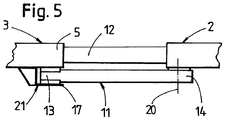
- Fig. 3 to 5 Detail views of anti-tip devices.
- An in Fig. 1 schematically represented Verladezug 1 consists of at least two Verladewagen 2, 3 for transporting and storing bulk material.
- Each Verladewagen 2, 3 is essentially of a supported on rail chassis 4 car frame 5, which has a storage box 6, constructed.
- a bottom conveyor belt 8 In the bottom area of the storage box 6 there is a bottom conveyor belt 8 extending in the longitudinal direction of the carriage 7 and adjacent thereto, a transfer conveyor belt 9 projecting over the carriage frame 5 and pivotable for transferring bulk goods to a further loading carriage 3.
- a Kippschutzvorraum 11 is provided between the - with respect to a transport direction 10 of the bottom conveyor belt 8 - foremost first Verladewagen 3 and the subsequent second Verladewagen 2 .
- the loading carriages 2, 3 are connected to each other by a coupling device 12.
- a front and a rear end 13, 14 ( 3 and 4 ) having tilting protection device 11 is attached to the rear end 14 on the second loading carriage 2.
- the front End 13 of the anti-tip device 11 is designed for contacting a rear end of the trolley frame 15 of the first loading trolley 3 or for releasable connection with the trolley frame end 15 in order to block an upward movement of the trolley frame 5.
- the front end 13 of the anti-tip device 11 is formed for a support on the rear carriage frame end 15 of the first loading carriage 3.
- the anti-tip device 11 has at the front end 13 a vertically adjustable Abstützstempel 16 for resting on the rear Wagenrahmenende 15 of the first Verladewagens 3 on.
- the support is expediently carried out on a support frame 17 attached to the carriage frame 5.
- the support punches 16 are advantageously designed as hydraulic cylinders; alternatively, a design as a spring element would also be conceivable.
- the anti-tip device 11 is connected to a control device 18, which is connected to measuring devices 19 for detecting a tilting movement of the foremost loading trolley 3.
- two mutually distanced Kippschutzvoroplastyen 11 are provided in a direction normal to the car longitudinal direction 7 car transverse direction.
- Fig. 2 shows the foremost Verladewagen 3 with swung out to the side transfer conveyor belt 9. Since the Verladewagen 3 also is in a track curve, he is already in a condition caused by the curve cant skew. Due to the weight of the bulk material to be discharged creates an additional burden. This results in a tilting moment (arrow 22), whereby the carriage frame 5 first experiences an upward movement and then lift the loading carriage 3 from an outer rail 23 of the track curve and could overturn. To compensate for the overturning moment or to keep the Verladewagen 3 in balance, which is located above the outer rail 23 Kippschvorraum 11 is applied. The hydraulic cylinder acts on the support frame 17 on the carriage frame 5 of the loading carriage 3 and thus prevents lifting of the loading carriage 3 of the rail 23. In a discharge to the other side, the opposite anti-tipper 11 is used in the same way.
- the anti-tip device 11 could also be attached to the car frame end 15 of the first loading carriage 3.
- the required contact or the releasable connection takes place in this alternative with the rear end 14 of the anti-tip device 11 on the carriage frame 5 of the second loading carriage. 2
Landscapes
- Engineering & Computer Science (AREA)
- Mechanical Engineering (AREA)
- Transportation (AREA)
- Architecture (AREA)
- Civil Engineering (AREA)
- Structural Engineering (AREA)
- Loading Or Unloading Of Vehicles (AREA)
- Machines For Laying And Maintaining Railways (AREA)
- Intermediate Stations On Conveyors (AREA)
- Framework For Endless Conveyors (AREA)
- Ship Loading And Unloading (AREA)
- Structure Of Belt Conveyors (AREA)
- Auxiliary Methods And Devices For Loading And Unloading (AREA)
- Vehicle Body Suspensions (AREA)
Description
- Die Erfindung betrifft einen Verladezug bestehend aus mindestens zwei Verladewagen zum Transportieren und Speichern von Schüttgut, mit je einem auf Schienenfahrwerken abgestützten Wagenrahmen, einem Speicherkasten mit einem in dessen Bodenbereich befindlichen, in Wagenlängsrichtung verlaufenden Bodenförderband und einem an dieses anschließenden, über den Wagenrahmen vorkragenden und verschwenkbaren Übergabeförderband.
- Ein derartiger Verladezug bzw. derartige Verladewagen sind bereits aus
EP 0 490 310 A1 oderDE 93 16 007 U1 bekannt. Diese weisen Einrichtungen zur Erhöhung der Standsicherheit auf. Diese Einrichtungen bestehen aus einer Blockiervorrichtung für das Übergabeförderband oder aus höhenverstellbaren Stützen, die sich auf der Schotterbettung abstützen. Damit wird ein Umkippen des Verladewagens vermieden. - Aus
EP 2 087 173 B1 ist eine Gleisbaumaschine, deren Rahmen ein Gelenk aufweist, ersichtlich. Um den Rahmen verwindungsfrei halten zu können, ist im Bereich des Gelenkes eine Vorrichtung zum Stabilisieren des Maschinenrahmens angeordnet. - Die Aufgabe der vorliegenden Erfindung liegt nun in der Schaffung eines Verladezuges der eingangs genannten Art, mit dem eine besonders sichere Entladung möglich ist.
- Diese Aufgabe wird erfindungsgemäß mit einem Verladezug der gattungsgemäßen Art durch die im kennzeichnenden Teil von Anspruch 1 angeführten Merkmale gelöst.
- Ein derartig ausgebildeter Verladezug kann bedenkenlos auch unter besonderen Bedingungen entladen werden. Die Kurvenüberhöhung im Gleisbogen oder ein zur Entladung quer zur Wagenlängsrichtung, maximal verschwenktes Übergabeförderband können eine Instabilität des vordersten Verladewagens verursachen, im Extremfall sogar ein Umkippen mit allen möglichen negativen Folgen für den gesamten Verladezug. Durch eine erfindungsgemäße Anordnung einer Kippschutzvorrichtung wird ein auftretendes Kippmoment des vordersten Verladewagens von der Kippschutzvorrichtung aufgenommen. Einer Gefahrensituation, also einer Aufwärtsbewegung des Wagenrahmens des vordersten Verladewagens wird sofort durch Einsatz der Kippschutzvorrichtung begegnet, wodurch umgehend wieder ein stabiler Gleichgewichtszustand erreicht ist.
- Weitere Vorteile der Erfindung ergeben sich aus den Unteransprüchen und der Zeichnungsbeschreibung.
- Im Folgenden wird die Erfindung anhand in der Zeichnung dargestellter Ausführungsbeispiele näher beschrieben. Es zeigen:
Fig. 1 eine schematische Seitenansicht eines Verladezuges,Fig. 2 einen vergrößerten Querschnitt durch den Verladezug gemäß Linie II inFig. 1 , undFig. 3 bis 5 Detailansichten von Kippschutzvorrichtungen. - Ein in
Fig. 1 schematisch dargestellter Verladezug 1 besteht aus mindestens zwei Verladewagen 2, 3 zum Transportieren und Speichern von Schüttgut. Jeder Verladewagen 2, 3 ist im Wesentlichen aus einem auf Schienenfahrwerken 4 abgestützten Wagenrahmen 5, der einen Speicherkasten 6 aufweist, aufgebaut. Im Bodenbereich des Speicherkastens 6 befindet sich ein in Wagenlängsrichtung 7 verlaufendes Bodenförderband 8 und an dieses anschließend, ist ein über den Wagenrahmen 5 vorkragendes und verschwenkbares Übergabeförderband 9 zur Weitergabe von Schüttgut auf einen weiteren Verladewagen 3 angeordnet. Zwischen dem - bezüglich einer Transportrichtung 10 des Bodenförderbandes 8 - vordersten ersten Verladewagen 3 und dem nachfolgenden zweiten Verladewagen 2 ist eine Kippschutzvorrichtung 11 vorgesehen. Die Verladewagen 2, 3 sind miteinander durch eine Kupplungseinrichtung 12 verbunden. - Die - bezüglich der Wagenlängsrichtung 7 - ein vorderes und ein hinteres Ende 13, 14 (
Fig. 3 und 4 ) aufweisende Kippschutzvorrichtung 11 ist mit dem hinteren Ende 14 am zweiten Verladewagen 2 befestigt. Das vordere Ende 13 der Kippschutzvorrichtung 11 ist für eine Kontaktierung eines hinteren Wagenrahmenendes 15 des ersten Verladewagens 3 bzw. für eine lösbare Verbindung mit dem Wagenrahmenende 15 ausgebildet, um eine Aufwärtsbewegung des Wagenrahmens 5 zu blockieren. - Wie in
Fig. 2 und 3 dargestellt, ist das vordere Ende 13 der Kippschutzvorrichtung 11 für eine Auflage auf dem hinteren Wagenrahmenende 15 des ersten Verladewagens 3 ausgebildet. Die Kippschutzvorrichtung 11 weist am vorderen Ende 13 einen in vertikaler Richtung verstellbaren Abstützstempel 16 zur Auflage am hinteren Wagenrahmenende 15 des ersten Verladewagens 3 auf. Die Auflage erfolgt zweckmäßigerweise auf einer am Wagenrahmen 5 angebrachten Abstützplatte 17. Die Abstützstempel 16 sind vorteilhafterweise als Hydraulikzylinder ausgebildet, alternativ wäre auch eine Ausbildung als Federelement denkbar. - Die Kippschutzvorrichtung 11 ist mit einer Steuereinrichtung 18 verbunden, welche mit Messeinrichtungen 19 zur Erfassung einer Kippbewegung des vordersten Verladewagens 3 verbunden ist.
- Wie vor allem in
Fig. 4 zu sehen ist, sind in einer normal zur Wagenlängsrichtung 7 verlaufenden Wagenquerrichtung zwei voneinander distanzierte Kippschutzvorrichtungen 11 vorgesehen. - Die in
Fig. 5 ersichtliche Kippschutzvorrichtung 11 ist um eine vertikale Achse 20 verschwenkbar am zweiten Verladewagen 2 befestigt. Durch die bei dieser Ausführungsform unterhalb des Wagenrahmens 5 des Verladewagens 3 angebrachte Abstützplatte 17 entsteht eine formschlüssige Verbindung 21 zwischen den beiden Verladewagen 2, 3. - Im Folgenden wird die Funktionsweise der Kippschutzvorrichtung 11 näher beschrieben.
Fig. 2 zeigt den vordersten Verladewagen 3 mit weit zur Seite ausgeschwenktem Übergabeförderband 9. Da sich der Verladewagen 3 außerdem in einem Gleisbogen befindet, ist er bereits in einer durch die Kurvenüberhöhung bedingten Schräglage. Durch das Gewicht des abzuwerfenden Schüttgutes entsteht eine zusätzliche Belastung. Daraus resultiert ein Kippmoment (Pfeil 22), wodurch der Wagenrahmen 5 zuerst eine Aufwärtsbewegung erfährt und dann der Verladewagen 3 von einer äußeren Schiene 23 des Gleisbogens abheben und umstürzen könnte. Um das Kippmoment auszugleichen bzw. den Verladewagen 3 im Gleichgewicht zu halten, wird die sich oberhalb der äußeren Schiene 23 befindliche Kippschutzvorrichtung 11 beaufschlagt. Der Hydraulikzylinder wirkt über die Abstützplatte 17 auf den Wagenrahmen 5 des Verladewagens 3 ein und verhindert so ein Abheben des Verladewagens 3 von der Schiene 23. Bei einer Entladung zur anderen Seite kommt auf gleiche Art und Weise die gegenüberliegende Kippschutzvorrichtung 11 zum Einsatz. - Durch die bereits beschriebene Verwendung der Steuer- und Messeinrichtungen 18, 19 kann die Registrierung des Kippmomentes und die Beaufschlagung der Kippschutzvorrichtungen 11 weitgehend automatisiert werden, wodurch Bedienungsfehler zuverlässig vermieden werden.
- Abschließend wird noch darauf hingewiesen, dass die Kippschutzvorrichtung 11 auch am Wagenrahmenende 15 des ersten Verladewagens 3 befestigt werden könnte. Die erforderliche Kontaktierung bzw. die lösbare Verbindung erfolgt bei dieser Alternative mit dem hinteren Ende 14 der Kippschutzvorrichtung 11 am Wagenrahmen 5 des zweiten Verladewagens 2.
Claims (6)
- Verladezug (1) bestehend aus mindestens zwei Verladewagen (2, 3) zum Transportieren und Speichern von Schüttgut, mit je einem auf Schienenfahrwerken (4) abgestützten Wagenrahmen (5), einem Speicherkasten (6) mit einem in dessen Bodenbereich befindlichen, in Wagenlängsrichtung (7) verlaufenden Bodenförderband (8) und einem an dieses anschließenden, über den Wagenrahmen (5) vorkragenden und verschwenkbaren Übergabeförderband (9) gekennzeichnet durch folgende Merkmale:a) zwischen dem - bezüglich einer Transportrichtung (10) des Bodenförderbandes (8) - vordersten ersten Verladewagen (3) und dem nachfolgenden zweiten Verladewagen (2) ist eine Kippschutzvorrichtung (11) vorgesehen,b) die - bezüglich der Wagenlängsrichtung (7) - ein vorderes und hinteres Ende (13, 14) aufweisende Kippschutzvorrichtung (11) ist mit dem hinteren Ende (14) am zweiten Verladewagen (2) befestigt,c) das vordere Ende (13) der Kippschutzvorrichtung (11) ist für eine Kontaktierung eines hinteren Wagenrahmenendes (15) des ersten Verladewagens (3) ausgebildet, um eine Aufwärtsbewegung des Wagenrahmens (5) des ersten Verladewagens (3) zu blockieren.
- Verladezug nach Anspruch 1, dadurch gekennzeichnet, dass das vordere Ende (13) der Kippschutzvorrichtung (11) für eine lösbare Verbindung mit dem hinteren Wagenrahmenende (15) des ersten Verladewagens (3) ausgebildet ist.
- Verladezug nach Anspruch 1, dadurch gekennzeichnet, dass das vordere Ende (13) der Kippschutzvorrichtung (11) für eine Auflage auf dem hinteren Wagenrahmenende (15) des ersten Verladewagens (3) ausgebildet ist.
- Verladezug nach Anspruch 3, dadurch gekennzeichnet, dass die Kippschutzvorrichtung (11) am vorderen Ende (13) einen in vertikaler Richtung verstellbaren Abstützstempel (16) zur Auflage am hinteren Wagenrahmenende (15) des ersten Verladewagens (3) aufweist.
- Verladezug nach Anspruch 1, dadurch gekennzeichnet, dass die Kippschutzvorrichtung (11) um eine vertikale Achse (20) verschwenkbar am zweiten Verladewagen (2) befestigt ist.
- Verladezug nach Anspruch 1, 2 oder 3, dadurch gekennzeichnet, dass in einer normal zur Wagenlängsrichtung (7) verlaufenden Wagenquerrichtung zwei voneinander distanzierte Kippschutzvorrichtungen (11) vorgesehen sind.
Priority Applications (1)
| Application Number | Priority Date | Filing Date | Title |
|---|---|---|---|
| PL15712524T PL3129555T3 (pl) | 2014-04-07 | 2015-03-13 | Pociąg załadowczy dla materiału sypkiego |
Applications Claiming Priority (2)
| Application Number | Priority Date | Filing Date | Title |
|---|---|---|---|
| ATGM153/2014U AT14306U1 (de) | 2014-04-07 | 2014-04-07 | Verladezug für Schüttgut |
| PCT/EP2015/000564 WO2015154844A1 (de) | 2014-04-07 | 2015-03-13 | Verladezug für schüttgut |
Publications (2)
| Publication Number | Publication Date |
|---|---|
| EP3129555A1 EP3129555A1 (de) | 2017-02-15 |
| EP3129555B1 true EP3129555B1 (de) | 2018-05-16 |
Family
ID=53773664
Family Applications (1)
| Application Number | Title | Priority Date | Filing Date |
|---|---|---|---|
| EP15712524.6A Active EP3129555B1 (de) | 2014-04-07 | 2015-03-13 | Verladezug für schüttgut |
Country Status (13)
| Country | Link |
|---|---|
| US (1) | US10252731B2 (de) |
| EP (1) | EP3129555B1 (de) |
| JP (1) | JP6538714B2 (de) |
| CN (1) | CN106163898A (de) |
| AT (1) | AT14306U1 (de) |
| AU (1) | AU2015245605B2 (de) |
| CA (1) | CA2940083C (de) |
| DK (1) | DK3129555T3 (de) |
| EA (1) | EA030505B1 (de) |
| ES (1) | ES2673047T3 (de) |
| PL (1) | PL3129555T3 (de) |
| TR (1) | TR201809586T4 (de) |
| WO (1) | WO2015154844A1 (de) |
Families Citing this family (3)
| Publication number | Priority date | Publication date | Assignee | Title |
|---|---|---|---|---|
| AT518477B1 (de) * | 2016-04-05 | 2018-10-15 | Plasser & Theurer Export Von Bahnbaumaschinen Gmbh | Verfahren und Transportfahrzeug zum Be- und Entladen |
| DE102018010037A1 (de) * | 2018-12-19 | 2020-06-25 | Robel Bahnbaumaschinen Gmbh | Schienenladezug zum Transport von langverschweißten Schienen |
| CN111874028A (zh) * | 2020-08-04 | 2020-11-03 | 安徽国钜工程机械科技有限公司 | 一种用于盾构工法水平运输机车的防脱轨系统 |
Family Cites Families (19)
| Publication number | Priority date | Publication date | Assignee | Title |
|---|---|---|---|---|
| US4191107A (en) * | 1978-10-02 | 1980-03-04 | Pullman Incorporated | Articulated railway car |
| GB2060046B (en) * | 1979-09-28 | 1983-06-08 | Coal Industry Patents Ltd | Swivelling apparatus |
| US4718351A (en) * | 1985-09-16 | 1988-01-12 | General Signal Corporation | Articulated coupling for integral trains |
| US4947761A (en) * | 1985-09-16 | 1990-08-14 | General Signal Corporation | Stub axle truck |
| ES2041557T3 (es) | 1990-12-14 | 1993-11-16 | Franz Plasser Bahnbaumaschinen- Industriegesellschaft M.B.H. | Vagon de carga para material a granel. |
| US5219262A (en) * | 1990-12-14 | 1993-06-15 | Franz Plasser Bahnbaumaschinen Industriegesellschaft M.B.H. | Freight car for transporting and storing bulk material |
| AT398993B (de) * | 1992-03-16 | 1995-02-27 | Plasser Bahnbaumasch Franz | Transportwagen mit einem auf schienenfahrwerken abgestützten wagenrahmen |
| US5271335A (en) * | 1992-09-25 | 1993-12-21 | Knorr Brake Holding Corporation | Articulation assembly for rail cars |
| DE9316007U1 (de) * | 1992-11-04 | 1994-01-05 | Franz Plasser Bahnbaumaschinen-Industriegesellschaft M.B.H., Wien | Verladewagen zum Speichern von Schüttgut |
| ATE146416T1 (de) * | 1992-11-18 | 1997-01-15 | Plasser Bahnbaumasch Franz | Verladewagen zum transport von schüttgut |
| DE59706089D1 (de) * | 1996-10-22 | 2002-02-28 | Plasser Bahnbaumasch Franz | Schüttgutverladewagen |
| ATE231940T1 (de) * | 1996-11-20 | 2003-02-15 | Plasser Bahnbaumasch Franz | Schüttgutverladewagen |
| AT404947B (de) * | 1997-02-12 | 1999-03-25 | Plasser Bahnbaumasch Franz | Wagen zur einschotterung eines gleises |
| CZ100598A3 (cs) * | 1997-05-14 | 1998-12-16 | Franz Plasser Bahnbaumaschinen-Industriegesellschaft M.B.H. | Nákladní vůz na sypký materiál |
| AT3961U3 (de) * | 2000-08-30 | 2001-07-25 | Plasser Bahnbaumasch Franz | Schüttgutverladewagen |
| AT6219U3 (de) * | 2002-07-23 | 2004-07-26 | Plasser Bahnbaumasch Franz | Verfahren zur beladung eines verladezuges |
| AT5703U3 (de) * | 2002-07-23 | 2003-09-25 | Plasser Bahnbaumasch Franz | Speicherwagen mit einer tasteinrichtung |
| AT503655B1 (de) * | 2006-10-31 | 2007-12-15 | Plasser Bahnbaumasch Franz | Gleisbaumaschine mit vorrichtung zum stabilisieren eines maschinenrahmens |
| FR2930502B1 (fr) * | 2008-04-23 | 2010-09-10 | Europ De Travaux Ferroviaires | Rame ferroviaire pour le transport de materiaux pondereux. |
-
2014
- 2014-04-07 AT ATGM153/2014U patent/AT14306U1/de not_active IP Right Cessation
-
2015
- 2015-03-13 JP JP2016561673A patent/JP6538714B2/ja active Active
- 2015-03-13 DK DK15712524.6T patent/DK3129555T3/en active
- 2015-03-13 EP EP15712524.6A patent/EP3129555B1/de active Active
- 2015-03-13 WO PCT/EP2015/000564 patent/WO2015154844A1/de active Application Filing
- 2015-03-13 AU AU2015245605A patent/AU2015245605B2/en active Active
- 2015-03-13 ES ES15712524.6T patent/ES2673047T3/es active Active
- 2015-03-13 CN CN201580018754.2A patent/CN106163898A/zh active Pending
- 2015-03-13 EA EA201600541A patent/EA030505B1/ru not_active IP Right Cessation
- 2015-03-13 PL PL15712524T patent/PL3129555T3/pl unknown
- 2015-03-13 TR TR2018/09586T patent/TR201809586T4/tr unknown
- 2015-03-13 CA CA2940083A patent/CA2940083C/en active Active
- 2015-03-13 US US15/301,998 patent/US10252731B2/en active Active
Non-Patent Citations (1)
| Title |
|---|
| None * |
Also Published As
| Publication number | Publication date |
|---|---|
| CA2940083C (en) | 2021-07-13 |
| JP2017518215A (ja) | 2017-07-06 |
| US10252731B2 (en) | 2019-04-09 |
| ES2673047T3 (es) | 2018-06-19 |
| TR201809586T4 (tr) | 2018-07-23 |
| WO2015154844A1 (de) | 2015-10-15 |
| CN106163898A (zh) | 2016-11-23 |
| AT14306U1 (de) | 2015-08-15 |
| CA2940083A1 (en) | 2015-10-15 |
| EP3129555A1 (de) | 2017-02-15 |
| DK3129555T3 (en) | 2018-08-27 |
| EA201600541A1 (ru) | 2017-01-30 |
| PL3129555T3 (pl) | 2018-10-31 |
| EA030505B1 (ru) | 2018-08-31 |
| AU2015245605A1 (en) | 2016-09-08 |
| US20170120936A1 (en) | 2017-05-04 |
| AU2015245605B2 (en) | 2018-10-11 |
| JP6538714B2 (ja) | 2019-07-03 |
Similar Documents
| Publication | Publication Date | Title |
|---|---|---|
| DE69803556T2 (de) | Eisenbahn- umschlageinrichtung für container und eisenbahnwagen | |
| EP2443285B1 (de) | Speicherwagen zum transport von schüttgut | |
| EP2576908A1 (de) | Fahrzeugkombination zum transport von schienen | |
| EP3129555B1 (de) | Verladezug für schüttgut | |
| EP1125812B1 (de) | Schüttgutverladewagen | |
| EP1995204B1 (de) | Vorrichtung zum Längsverstellen eines Spreaders | |
| DE102012018575B4 (de) | Schwerlast-Transportfahrzeug mit einem Fahrgestell und einem nur durch Hydraulikzylinder mit dem Fahrgestell verbundenen Lastauflagebett | |
| EP3440261B1 (de) | Verfahren zum be- und entladen eines gleisverfahrbaren transportfahrzeuges | |
| AT517048B1 (de) | Speicherwagen für Schüttgut | |
| CH640285A5 (de) | Selbstfahrbare gleisbaumaschine. | |
| DE102018113698B4 (de) | Verfahrbarer Grubenübertritt | |
| EP2723620B1 (de) | Verladewagen für schüttgut | |
| DE1680191A1 (de) | Transportfahrzeug fuer den wahlweisen Transport von verschiedenartigem Ladegut | |
| AT503655B1 (de) | Gleisbaumaschine mit vorrichtung zum stabilisieren eines maschinenrahmens | |
| DE1912830B2 (de) | Lastkraftwagen für den Transport von mit Stützen versehenen Wechselaufbauten | |
| DE102009040850B4 (de) | Holzspalter | |
| DE102006014213A1 (de) | Kippeinrichtung | |
| DE197893C (de) | ||
| DE102006007822B4 (de) | Kippschalenförderer | |
| DE2011593C3 (de) | Fahrgestell für Lastkraftwagenanhänger zum Transport auswechselbarer Ladeaufbauten | |
| DE1215740B (de) | Transportwagen, insbesondere Transport-schienenfahrzeug, mit zwei uebereinanderliegenden Ladeflaechen | |
| DE102006062303A1 (de) | Transport- und Ladewagen für Flugzeugsitze | |
| DE29604183U1 (de) | Die Querverladung von Straßenfahrzeugen auf Schienenfahrzeuge | |
| DE4118687C2 (de) | Fahrzeug-Mittenbereich für Taschenwagen | |
| DE1289438B (de) | Lastfahrzeug, insbesondere Tieflader fuer den Transport von Fertigbauteilen |
Legal Events
| Date | Code | Title | Description |
|---|---|---|---|
| STAA | Information on the status of an ep patent application or granted ep patent |
Free format text: STATUS: THE INTERNATIONAL PUBLICATION HAS BEEN MADE |
|
| PUAI | Public reference made under article 153(3) epc to a published international application that has entered the european phase |
Free format text: ORIGINAL CODE: 0009012 |
|
| STAA | Information on the status of an ep patent application or granted ep patent |
Free format text: STATUS: REQUEST FOR EXAMINATION WAS MADE |
|
| 17P | Request for examination filed |
Effective date: 20161007 |
|
| AK | Designated contracting states |
Kind code of ref document: A1 Designated state(s): AL AT BE BG CH CY CZ DE DK EE ES FI FR GB GR HR HU IE IS IT LI LT LU LV MC MK MT NL NO PL PT RO RS SE SI SK SM TR |
|
| AX | Request for extension of the european patent |
Extension state: BA ME |
|
| DAV | Request for validation of the european patent (deleted) | ||
| DAX | Request for extension of the european patent (deleted) | ||
| GRAP | Despatch of communication of intention to grant a patent |
Free format text: ORIGINAL CODE: EPIDOSNIGR1 |
|
| STAA | Information on the status of an ep patent application or granted ep patent |
Free format text: STATUS: GRANT OF PATENT IS INTENDED |
|
| INTG | Intention to grant announced |
Effective date: 20171214 |
|
| GRAS | Grant fee paid |
Free format text: ORIGINAL CODE: EPIDOSNIGR3 |
|
| GRAA | (expected) grant |
Free format text: ORIGINAL CODE: 0009210 |
|
| STAA | Information on the status of an ep patent application or granted ep patent |
Free format text: STATUS: THE PATENT HAS BEEN GRANTED |
|
| AK | Designated contracting states |
Kind code of ref document: B1 Designated state(s): AL AT BE BG CH CY CZ DE DK EE ES FI FR GB GR HR HU IE IS IT LI LT LU LV MC MK MT NL NO PL PT RO RS SE SI SK SM TR |
|
| REG | Reference to a national code |
Ref country code: GB Ref legal event code: FG4D Free format text: NOT ENGLISH |
|
| REG | Reference to a national code |
Ref country code: CH Ref legal event code: EP |
|
| REG | Reference to a national code |
Ref country code: IE Ref legal event code: FG4D Free format text: LANGUAGE OF EP DOCUMENT: GERMAN |
|
| REG | Reference to a national code |
Ref country code: DE Ref legal event code: R096 Ref document number: 502015004298 Country of ref document: DE |
|
| REG | Reference to a national code |
Ref country code: AT Ref legal event code: REF Ref document number: 999678 Country of ref document: AT Kind code of ref document: T Effective date: 20180615 |
|
| REG | Reference to a national code |
Ref country code: ES Ref legal event code: FG2A Ref document number: 2673047 Country of ref document: ES Kind code of ref document: T3 Effective date: 20180619 |
|
| REG | Reference to a national code |
Ref country code: RO Ref legal event code: EPE |
|
| REG | Reference to a national code |
Ref country code: DK Ref legal event code: T3 Effective date: 20180820 |
|
| REG | Reference to a national code |
Ref country code: NL Ref legal event code: FP |
|
| REG | Reference to a national code |
Ref country code: SE Ref legal event code: TRGR |
|
| REG | Reference to a national code |
Ref country code: LT Ref legal event code: MG4D |
|
| REG | Reference to a national code |
Ref country code: NO Ref legal event code: T2 Effective date: 20180516 |
|
| PG25 | Lapsed in a contracting state [announced via postgrant information from national office to epo] |
Ref country code: BG Free format text: LAPSE BECAUSE OF FAILURE TO SUBMIT A TRANSLATION OF THE DESCRIPTION OR TO PAY THE FEE WITHIN THE PRESCRIBED TIME-LIMIT Effective date: 20180816 Ref country code: LT Free format text: LAPSE BECAUSE OF FAILURE TO SUBMIT A TRANSLATION OF THE DESCRIPTION OR TO PAY THE FEE WITHIN THE PRESCRIBED TIME-LIMIT Effective date: 20180516 Ref country code: FI Free format text: LAPSE BECAUSE OF FAILURE TO SUBMIT A TRANSLATION OF THE DESCRIPTION OR TO PAY THE FEE WITHIN THE PRESCRIBED TIME-LIMIT Effective date: 20180516 |
|
| PG25 | Lapsed in a contracting state [announced via postgrant information from national office to epo] |
Ref country code: LV Free format text: LAPSE BECAUSE OF FAILURE TO SUBMIT A TRANSLATION OF THE DESCRIPTION OR TO PAY THE FEE WITHIN THE PRESCRIBED TIME-LIMIT Effective date: 20180516 Ref country code: RS Free format text: LAPSE BECAUSE OF FAILURE TO SUBMIT A TRANSLATION OF THE DESCRIPTION OR TO PAY THE FEE WITHIN THE PRESCRIBED TIME-LIMIT Effective date: 20180516 Ref country code: GR Free format text: LAPSE BECAUSE OF FAILURE TO SUBMIT A TRANSLATION OF THE DESCRIPTION OR TO PAY THE FEE WITHIN THE PRESCRIBED TIME-LIMIT Effective date: 20180817 Ref country code: HR Free format text: LAPSE BECAUSE OF FAILURE TO SUBMIT A TRANSLATION OF THE DESCRIPTION OR TO PAY THE FEE WITHIN THE PRESCRIBED TIME-LIMIT Effective date: 20180516 |
|
| PG25 | Lapsed in a contracting state [announced via postgrant information from national office to epo] |
Ref country code: SK Free format text: LAPSE BECAUSE OF FAILURE TO SUBMIT A TRANSLATION OF THE DESCRIPTION OR TO PAY THE FEE WITHIN THE PRESCRIBED TIME-LIMIT Effective date: 20180516 Ref country code: EE Free format text: LAPSE BECAUSE OF FAILURE TO SUBMIT A TRANSLATION OF THE DESCRIPTION OR TO PAY THE FEE WITHIN THE PRESCRIBED TIME-LIMIT Effective date: 20180516 |
|
| REG | Reference to a national code |
Ref country code: DE Ref legal event code: R097 Ref document number: 502015004298 Country of ref document: DE |
|
| PG25 | Lapsed in a contracting state [announced via postgrant information from national office to epo] |
Ref country code: SM Free format text: LAPSE BECAUSE OF FAILURE TO SUBMIT A TRANSLATION OF THE DESCRIPTION OR TO PAY THE FEE WITHIN THE PRESCRIBED TIME-LIMIT Effective date: 20180516 |
|
| PLBE | No opposition filed within time limit |
Free format text: ORIGINAL CODE: 0009261 |
|
| STAA | Information on the status of an ep patent application or granted ep patent |
Free format text: STATUS: NO OPPOSITION FILED WITHIN TIME LIMIT |
|
| 26N | No opposition filed |
Effective date: 20190219 |
|
| PG25 | Lapsed in a contracting state [announced via postgrant information from national office to epo] |
Ref country code: SI Free format text: LAPSE BECAUSE OF FAILURE TO SUBMIT A TRANSLATION OF THE DESCRIPTION OR TO PAY THE FEE WITHIN THE PRESCRIBED TIME-LIMIT Effective date: 20180516 |
|
| PG25 | Lapsed in a contracting state [announced via postgrant information from national office to epo] |
Ref country code: MC Free format text: LAPSE BECAUSE OF FAILURE TO SUBMIT A TRANSLATION OF THE DESCRIPTION OR TO PAY THE FEE WITHIN THE PRESCRIBED TIME-LIMIT Effective date: 20180516 |
|
| PG25 | Lapsed in a contracting state [announced via postgrant information from national office to epo] |
Ref country code: LU Free format text: LAPSE BECAUSE OF NON-PAYMENT OF DUE FEES Effective date: 20190313 Ref country code: AL Free format text: LAPSE BECAUSE OF FAILURE TO SUBMIT A TRANSLATION OF THE DESCRIPTION OR TO PAY THE FEE WITHIN THE PRESCRIBED TIME-LIMIT Effective date: 20180516 |
|
| PG25 | Lapsed in a contracting state [announced via postgrant information from national office to epo] |
Ref country code: IE Free format text: LAPSE BECAUSE OF NON-PAYMENT OF DUE FEES Effective date: 20190313 |
|
| PG25 | Lapsed in a contracting state [announced via postgrant information from national office to epo] |
Ref country code: PT Free format text: LAPSE BECAUSE OF FAILURE TO SUBMIT A TRANSLATION OF THE DESCRIPTION OR TO PAY THE FEE WITHIN THE PRESCRIBED TIME-LIMIT Effective date: 20180917 Ref country code: MT Free format text: LAPSE BECAUSE OF FAILURE TO SUBMIT A TRANSLATION OF THE DESCRIPTION OR TO PAY THE FEE WITHIN THE PRESCRIBED TIME-LIMIT Effective date: 20180516 |
|
| PG25 | Lapsed in a contracting state [announced via postgrant information from national office to epo] |
Ref country code: CY Free format text: LAPSE BECAUSE OF FAILURE TO SUBMIT A TRANSLATION OF THE DESCRIPTION OR TO PAY THE FEE WITHIN THE PRESCRIBED TIME-LIMIT Effective date: 20180516 |
|
| PG25 | Lapsed in a contracting state [announced via postgrant information from national office to epo] |
Ref country code: IS Free format text: LAPSE BECAUSE OF FAILURE TO SUBMIT A TRANSLATION OF THE DESCRIPTION OR TO PAY THE FEE WITHIN THE PRESCRIBED TIME-LIMIT Effective date: 20180916 |
|
| PG25 | Lapsed in a contracting state [announced via postgrant information from national office to epo] |
Ref country code: HU Free format text: LAPSE BECAUSE OF FAILURE TO SUBMIT A TRANSLATION OF THE DESCRIPTION OR TO PAY THE FEE WITHIN THE PRESCRIBED TIME-LIMIT; INVALID AB INITIO Effective date: 20150313 |
|
| PG25 | Lapsed in a contracting state [announced via postgrant information from national office to epo] |
Ref country code: MK Free format text: LAPSE BECAUSE OF FAILURE TO SUBMIT A TRANSLATION OF THE DESCRIPTION OR TO PAY THE FEE WITHIN THE PRESCRIBED TIME-LIMIT Effective date: 20180516 |
|
| P01 | Opt-out of the competence of the unified patent court (upc) registered |
Effective date: 20230528 |
|
| PGFP | Annual fee paid to national office [announced via postgrant information from national office to epo] |
Ref country code: DE Payment date: 20230526 Year of fee payment: 9 |
|
| PGFP | Annual fee paid to national office [announced via postgrant information from national office to epo] |
Ref country code: NL Payment date: 20240311 Year of fee payment: 10 |
|
| PGFP | Annual fee paid to national office [announced via postgrant information from national office to epo] |
Ref country code: AT Payment date: 20240223 Year of fee payment: 10 |
|
| PGFP | Annual fee paid to national office [announced via postgrant information from national office to epo] |
Ref country code: RO Payment date: 20240229 Year of fee payment: 10 Ref country code: CZ Payment date: 20240229 Year of fee payment: 10 Ref country code: GB Payment date: 20240215 Year of fee payment: 10 |
|
| PGFP | Annual fee paid to national office [announced via postgrant information from national office to epo] |
Ref country code: TR Payment date: 20240304 Year of fee payment: 10 Ref country code: SE Payment date: 20240312 Year of fee payment: 10 Ref country code: PL Payment date: 20240305 Year of fee payment: 10 Ref country code: NO Payment date: 20240227 Year of fee payment: 10 Ref country code: IT Payment date: 20240329 Year of fee payment: 10 Ref country code: FR Payment date: 20240320 Year of fee payment: 10 Ref country code: DK Payment date: 20240312 Year of fee payment: 10 Ref country code: BE Payment date: 20240311 Year of fee payment: 10 |
|
| PGFP | Annual fee paid to national office [announced via postgrant information from national office to epo] |
Ref country code: CH Payment date: 20240401 Year of fee payment: 10 |
|
| PGFP | Annual fee paid to national office [announced via postgrant information from national office to epo] |
Ref country code: ES Payment date: 20240403 Year of fee payment: 10 |