EP3114044B1 - Zigarettenpackung - Google Patents
Zigarettenpackung Download PDFInfo
- Publication number
- EP3114044B1 EP3114044B1 EP15703459.6A EP15703459A EP3114044B1 EP 3114044 B1 EP3114044 B1 EP 3114044B1 EP 15703459 A EP15703459 A EP 15703459A EP 3114044 B1 EP3114044 B1 EP 3114044B1
- Authority
- EP
- European Patent Office
- Prior art keywords
- tab
- tear
- opening
- blank
- end wall
- Prior art date
- Legal status (The legal status is an assumption and is not a legal conclusion. Google has not performed a legal analysis and makes no representation as to the accuracy of the status listed.)
- Revoked
Links
Images


Classifications
-
- B—PERFORMING OPERATIONS; TRANSPORTING
- B65—CONVEYING; PACKING; STORING; HANDLING THIN OR FILAMENTARY MATERIAL
- B65D—CONTAINERS FOR STORAGE OR TRANSPORT OF ARTICLES OR MATERIALS, e.g. BAGS, BARRELS, BOTTLES, BOXES, CANS, CARTONS, CRATES, DRUMS, JARS, TANKS, HOPPERS, FORWARDING CONTAINERS; ACCESSORIES, CLOSURES, OR FITTINGS THEREFOR; PACKAGING ELEMENTS; PACKAGES
- B65D75/00—Packages comprising articles or materials partially or wholly enclosed in strips, sheets, blanks, tubes, or webs of flexible sheet material, e.g. in folded wrappers
- B65D75/52—Details
- B65D75/58—Opening or contents-removing devices added or incorporated during package manufacture
- B65D75/5827—Tear-lines provided in a wall portion
- B65D75/5833—Tear-lines provided in a wall portion for tearing out a portion of the wall
- B65D75/5838—Tear-lines provided in a wall portion for tearing out a portion of the wall combined with separate fixed tearing means, e.g. tabs
-
- B—PERFORMING OPERATIONS; TRANSPORTING
- B65—CONVEYING; PACKING; STORING; HANDLING THIN OR FILAMENTARY MATERIAL
- B65D—CONTAINERS FOR STORAGE OR TRANSPORT OF ARTICLES OR MATERIALS, e.g. BAGS, BARRELS, BOTTLES, BOXES, CANS, CARTONS, CRATES, DRUMS, JARS, TANKS, HOPPERS, FORWARDING CONTAINERS; ACCESSORIES, CLOSURES, OR FITTINGS THEREFOR; PACKAGING ELEMENTS; PACKAGES
- B65D85/00—Containers, packaging elements or packages, specially adapted for particular articles or materials
- B65D85/07—Containers, packaging elements or packages, specially adapted for particular articles or materials for compressible or flexible articles
- B65D85/08—Containers, packaging elements or packages, specially adapted for particular articles or materials for compressible or flexible articles rod-shaped or tubular
- B65D85/10—Containers, packaging elements or packages, specially adapted for particular articles or materials for compressible or flexible articles rod-shaped or tubular for cigarettes
- B65D85/1036—Containers formed by erecting a rigid or semi-rigid blank
-
- B—PERFORMING OPERATIONS; TRANSPORTING
- B65—CONVEYING; PACKING; STORING; HANDLING THIN OR FILAMENTARY MATERIAL
- B65D—CONTAINERS FOR STORAGE OR TRANSPORT OF ARTICLES OR MATERIALS, e.g. BAGS, BARRELS, BOTTLES, BOXES, CANS, CARTONS, CRATES, DRUMS, JARS, TANKS, HOPPERS, FORWARDING CONTAINERS; ACCESSORIES, CLOSURES, OR FITTINGS THEREFOR; PACKAGING ELEMENTS; PACKAGES
- B65D5/00—Rigid or semi-rigid containers of polygonal cross-section, e.g. boxes, cartons or trays, formed by folding or erecting one or more blanks made of paper
- B65D5/42—Details of containers or of foldable or erectable container blanks
- B65D5/54—Lines of weakness to facilitate opening of container or dividing it into separate parts by cutting or tearing
- B65D5/548—Lines of weakness to facilitate opening of container or dividing it into separate parts by cutting or tearing for opening containers formed by erecting a blank to U-shape
-
- B—PERFORMING OPERATIONS; TRANSPORTING
- B65—CONVEYING; PACKING; STORING; HANDLING THIN OR FILAMENTARY MATERIAL
- B65D—CONTAINERS FOR STORAGE OR TRANSPORT OF ARTICLES OR MATERIALS, e.g. BAGS, BARRELS, BOTTLES, BOXES, CANS, CARTONS, CRATES, DRUMS, JARS, TANKS, HOPPERS, FORWARDING CONTAINERS; ACCESSORIES, CLOSURES, OR FITTINGS THEREFOR; PACKAGING ELEMENTS; PACKAGES
- B65D5/00—Rigid or semi-rigid containers of polygonal cross-section, e.g. boxes, cartons or trays, formed by folding or erecting one or more blanks made of paper
- B65D5/42—Details of containers or of foldable or erectable container blanks
- B65D5/70—Break-in flaps, or members adapted to be torn-off, to provide pouring openings
- B65D5/708—Separate tearable flexible elements covering a discharge opening of a container, e.g. adhesive tape
-
- B—PERFORMING OPERATIONS; TRANSPORTING
- B65—CONVEYING; PACKING; STORING; HANDLING THIN OR FILAMENTARY MATERIAL
- B65D—CONTAINERS FOR STORAGE OR TRANSPORT OF ARTICLES OR MATERIALS, e.g. BAGS, BARRELS, BOTTLES, BOXES, CANS, CARTONS, CRATES, DRUMS, JARS, TANKS, HOPPERS, FORWARDING CONTAINERS; ACCESSORIES, CLOSURES, OR FITTINGS THEREFOR; PACKAGING ELEMENTS; PACKAGES
- B65D77/00—Packages formed by enclosing articles or materials in preformed containers, e.g. boxes, cartons, sacks or bags
- B65D77/02—Wrapped articles enclosed in rigid or semi-rigid containers
Definitions
- the invention relates to cigarette packs having the features of the preamble of claim 1.
- a trained according to the concept of a soft cup pack cigarette pack with a reusable closure of an inner pack is known by WO 2012/007081 A1 ,
- an outer pack is cup-shaped, so open at the top.
- An inner pack consists of a lining of tinfoil surrounding a group of cigarettes.
- the reusable closure consists of an adhesive label, which extends over the front side of the package and is fixed surface by means of releasable adhesive to the outer package on the one hand and the inner package on the other. The latter has, in the region of a recess of the front wall of the outer pack, a tear-off tab defined by lines of weakness.
- a cigarette pack in which the inner pack is formed as a sealing pack with a surrounding the cigarette group, thermally sealable and moisture-proof film. This forms lateral fin seams and a transverse seam.
- a multiply usable opening aid is formed in the region of the inner pack as a opening tab, which extends across the width of the end wall and a frontal area the front wall extends. An end piece of the tab is fixable with glue points on an inner layer of the inner pack in the closed position.
- the outer pack is designed in the manner of a folding pack with locking tab which extends over the front side and an upper region of the front side. The opening tab of the inner pack is connected to the locking tab, so it is operated with this opening and closing.
- This package is complex and complex in terms of the material to be used and in terms of construction. The production of such a package is difficult ( EP 2 455 302 A1 ).
- the essentially parallelepipedic packs shown in the drawings are used to hold a group of cigarettes 10.
- the dimensions of the packs are selected such that groups of cigarettes 11 with cigarettes 11 arranged in three rows can be accommodated ( Fig. 16 . Fig. 18 ).
- the package consists of at least one outer package 12 and one inner package 13. Furthermore, the package may be provided with a (conventional) outer envelope made of cellophane or plastic film (not shown).
- the outer package 12 consists of an outer panel 14 of foldable packaging material, in particular thin cardboard, paper or rigid-soft packaging material.
- the outer panel 14 is formed so that the package contents, so the inner pack 13, is completely enclosed on all sides.
- the outer panel 14 accordingly forms an outer front wall 15, an outer rear wall 16, an outer bottom wall 17 and an outer end wall 18.
- side tabs are arranged, namely outer side tabs 19 on the front wall 15th and inner side flaps 20 on the rear wall 16.
- the side flaps 19 and 20 are in the finished package by glue - glue dots 21 on the outer side tabs 19 - interconnected and form outer side walls 22, 23 of the finished package.
- a special feature is that upright packing edges are formed as round edges 24, so in a quarter circle in cross-section, approximately corresponding to the dimension of a cigarette 10.
- the round edges 24 are defined by a group of parallel grooves 25 of the outer blank 14.
- the outer bottom wall 17 and the outer end wall 18 are provided with correspondingly formed round corners 26.
- the outer panel 14 is constructed according to the L Lucassfalttama, but with a special order of the walls. Between the outer front wall 15 and the outer rear wall 16 is the outer end wall 18. This is therefore free of connecting tabs.
- the outer bottom wall 17 connects to the free end of the outer rear wall 16 at.
- a - trapezoidal - connecting tabs 27 is attached. This is in the finished package on the inside of the outer front wall 15 and is connected thereto, in this case by (three arranged in series) glue points 28. Corner tabs 29, 30 serve to connect the outer side walls 22, 23 with the bottom wall 17th or end wall 18.
- the corner tabs 29, 30 abut against the inside of the bottom wall 17 and the end wall 18 and are fixed there by means of glue (two glue points 31).
- the inner package 13 from an inner blank 32 (FIG. Fig. 13 ) is matched with respect to the design of the outer package 12.
- the inner blank 32 is made of thin, foldable packaging material, namely paper, tin foil or foil.
- inner front wall 33, inner rear wall 34 and disposed therebetween inner end wall 35 are defined successively according to the longitudinal folding principle.
- bottom tabs 36, 37 At the ends of front wall 33 and rear wall 34 are bottom tabs 36, 37 which form an inner bottom wall by appropriate folding and mutual overlap.
- inner side walls are formed from lateral wall tabs 38, 39 and partially overlap each other in the folded position ( Fig. 16 . Fig.
- a special feature of the pack is an opening aid. This can be designed for a repeated opening and closing operation or for a single opening operation. Furthermore, the opening aid can alternatively be designed such that upon actuation of the same a removal opening 40 in the region of outer package 12 and inner package 13 at the same time or only an opening in the region of the outer package 12 is created. In the latter case, the inner pack 13 must be opened by the consumer (manually). In the embodiment according to Fig. 1 to Fig. 3 combined with Fig. 13 the opening aid is arranged in the region of the outer end wall 18, transversely to this.
- the removal opening 40 is created by special interaction of outer pack 12 and inner pack 13.
- the outer panel 14 is provided with an opening 40 corresponding to the opening opening 41. This is formed as part of the outer panel 14 and bounded by a weakening line 42, which is preferably a perforation line. This is substantially U-shaped, with the open side in the region of the outer rear wall 16.
- the opening tab 41 is cut out of the composite with the outer panel 14 along the line of weakness 42. Due to the formation of the weakening line 42, however, the opening tab 41 remains in communication with the outer panel 14, with one leg of the rear wall 16.
- the opening tab 41 is moved by an aid in the open position, in particular by a closure label 43.
- This consists of foil and is connected by gluing to the outside of the outer panel 14.
- the closure label 43 is formed - as a separate blank - so that the opening tab 41 is completely covered to form a running around edge strip 44. This is connected to a portion of the outer panel 14 adjacent to the line of weakness 42.
- the opening aid or the closure label 43 is arranged laterally offset from an imaginary central transverse plane of the end wall 18.
- the corner tabs 13 lying on this side are shortened accordingly, so that in the folded position the corner tabs lie outside the area of the removal opening 40 (FIG. Fig. 2 ).
- the inner package 13 or its inner cut 32 is provided with a cut-out area which can be separated out to form the removal opening 40, in particular with a tear-off tab 46.
- This is in terms of position or relative position within the inner blank 32, matched in size and / or contour to the opening tab 41 of the outer panel 14.
- the tear-off tab 46 is defined by a weakening line 47, in particular by a perforation line in the material of the inner blank, such that when the opening aid is actuated, the tear-off tab 46 is at the same time completely or partially cut out of the connection with the inner blank 32.
- the (shown in detail) inner blank 32 according to Fig. 13 is provided with a substantially rectangular tear-off tab 46, which extends transversely across the inner end wall 35, in a relative to the opening tab 41 of the outer panel 14 aligned relative position.
- the arrangement is selected so that the tear-off tab 46 is slightly smaller in dimensions than the opening tab 41, so that even with minor manufacturing tolerances, the tear-off tab 46 lies completely within the area of the opening tab 41.
- the tear-off tab 46 is bounded by a closed, all-around weakening line 47.
- the tear-off tab 46 is connected as part of the inner pack 13 (permanently) to the opening tab 41 of the outer pack 12.
- the predominant surface of the tear-off tab 46, at least in the area of the inner front wall 33 and the inner end wall 35, is connected by glue to the inner side of the opening tab 41.
- a plurality of glue points 48 are arranged distributed, in particular in corner regions of the tear-off tab 46 or the separable legs thereof.
- opening tab 41 and tear-off tab 46 is in an operation of the opening tab 41 - in the embodiment according to Fig. 1 to Fig. 3 through the closure label 43 - pieces of material from the outer pack 12 and from the inner pack 13 simultaneously separated out to form the removal opening 14.
- these blank parts 41, 46 can be returned by means of the closure label 43 in the closed position.
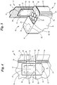
- Fig. 4, Fig. 5 discloses an opening aid according to the invention.
- the basic structure with opening tab 41 and tear tab 46 and preferably with closure label 43 corresponds to the described embodiment.
- the opening tab 41 of the outer package 12 is presently positioned only in the region of the outer end wall 18 and extends with a section or leg into the outer rear wall 16 (FIG. Fig. 4 ).
- a (front) tear-off edge 49 of the opening tab 41 runs along a folded edge 50 between the outer front wall 15 and outer end wall 18.
- the line of weakness 42 is in this area - as well as in the embodiment of Fig. 3 - Formed with a longer, transverse punched cut, so that the entrainment of the opening tab 41 is ensured by the closure label 43 when first opened.
- the effective area of the opening tab 41 extends across the width or depth of the outer end wall 18, so that the removal opening formed also lies exclusively in the area of the outer end wall 18.
- the closure label 43 extends with a (longer) leg into the outer front wall 15.
- the grip tab 45th The inner package 13 or the inner blank 32 is aligned with the design of the opening aid.
- the inner blank 32 is corresponding in the area of the opening aid Fig. 14 educated.
- the tear-off tab 46 extends in the region of the inner end wall 35 with a transverse tear line 51 along a folding line 52 delimiting the inner end wall 35.
- a short leg of the tear-off tab 46 lies in the inner rear wall 34.
- the thus formed tear-off tab 46 is in its position substantially centered on the opening tab 41 according to Fig. 4, Fig. 5 aligned and with this durable connected by (four) glue points 48.
- the unit of opening tab 41 and tear-off tab 46 is guided together in the open position - with the closure label 43.
- the opening tab 41 and tear tab 46 can be returned by opposite operation in the closed position.
- the opening aid may alternatively, but not according to the invention, be formed without a closure label.
- the opening tab 41 is formed and / or arranged so that a portion or an edge region of the opening tab 41 directly detected and then the unit can be brought out of opening tab 41 and tear-off tab 46 in the open position.
- Fig. 7 is arranged by a preferably closed weakening line 42 or perforation a (rectangular) area as opening tab 41 of the outer end wall 18.
- the punching of the line 42 is formed so that on a transverse side - in this case on the outer front wall 15 facing side - a continuous punching cut 67 is arranged. Due to arcuate ends of the punching 67, a narrow grip tongue 53 of the opening tab 41 is formed.
- the arrangement is such that the grip tongue 53 or the punching 67 associated therewith is arranged in the region of an adjacent wall of the outer cut 14, in the present case in the region of the outer cut. Front wall 15.
- the grip tongue 53 Due to the folding of the blank 14 along the front-side folded edge 50, the grip tongue 53 is positioned at an angle or inclination to the front wall 15 due to the restoring forces in the material ( Fig. 7 ). The grip tongue 53 is thereby easily detectable. The opening tab 41 can then be moved into an open position, preferably with separation from the outer end wall 18th
- the inner blank 32 can with respect to the arrangement and design of the tear-tab 46 accordingly Fig. 14 be educated.
- gluing the unit of opening tab 41 and tear-off tab 46 is made, which is completely removed from inner pack 13 and outer pack 12, due to a transverse perforation 54 of the opening tab 41 opposite to the grip tongue 53, in this case at the top of the outer rear wall 16. It arises such a free removal opening, which is not closed again.
- the outer panel 14 may alternatively be configured such that blank parts lying in the spatial vicinity of the opening tab 41, due to a (special) design and / or folding position, make it possible to detect the opening tab during the (initial) opening.
- Fig. 9 serves a peripheral edge of a wall of the outer package 12 as an actuating means for the opening tab 41. This is due to a corresponding line of weakness in the edge region or on one side of the outer end wall 18 is arranged.
- a free transverse edge 55 of the outer end wall 18 forms due to appropriate design of the outer panel a detectable free projection for actuating the opening tab 41.
- the outer end wall 18 with the transverse edge 55 projects due to appropriate design of the outer panel 14 slightly beyond the contour of the outer package 12 and the outer side wall 23 away.
- the opening tab 41 is thus detected immediately and separated along the line of weakness 42 as a portion of the outer end wall 18.
- a parting line 56 is designed as a weakening line, in particular with punched holes and residual connections.
- the opening tab 41 is in the embodiment Fig. 8, Fig. 9 trained in a special way.
- a substantially rectangular center piece 57 extends within the outer end wall 18. This is therefore part of the opening tab 41.
- side pieces 58, 59 arranged by the correspondingly contoured weakening line 42, this as part of the front wall 15 on the one hand and the rear wall 16 are formed on the other hand.
- An obliquely extending perforation section 60 allows the separation process in the region of front wall 15 and rear wall 16, so that the side pieces 58, 59 have a trapezoidal contour. Accordingly, the (permanent) removal opening is formed. Upper ends of the cigarettes 10 are exposed in the region of front wall 15 and / or rear wall 16.
- the inner blank 32 is in terms of the shape of the tear-off tab (not shown) to the contour of the opening tab 41 in Fig. 8, Fig. 9 customized.
- the number and positioning of the glue dots 48 takes into account the side pieces 58, 59 of the opening tab 41 associated areas of the tear-off tab.
- a portion of the outer panel 14 serves as a means for actuating the opening tab 41.
- This is exemplified as (rectangular) end or side piece of the end wall 18th educated. Due to a closed weakening or perforation line 42, an opening tab 41 is defined whose width corresponds to the corresponding dimension of the outer end wall 18 and whose length preferably corresponds approximately to half the length of the end wall 18. The opening tab 41 with tear tab 46 is removed at the first actuation.
- the actuation of the opening tab 41 when putting the pack into use is effected by means of a grip piece 61, which protrudes beyond the contour of the end wall 18, ie beyond its transverse edge 55.
- the handle 61 is part of the correspondingly formed corner flap 30. This is provided with a transverse punch 62 with arcuate ends. In the folded position - system of the corner tab 30 on the inside of the end wall 18 - the handle 61 is directed due to the transverse punch 62 to the outside. The dimensions are chosen so that the handle 61 forms an outwardly directed projection.
- the tongue-shaped grip 61 is located in the region of a cutout 66 which is formed by corresponding shortening of the outer side flap 19 (FIG. Fig. 10 ) is created.
- the weakening line 42 adjoins the ends of the transverse edge 55 and the round corners 26 of the end wall 18 and thus form a continuation of the wall edge, so that the separation of the opening tab 41 is facilitated.
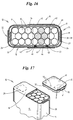
- the inner package 13 or its inner cut 32 is preferably in the region of the tear-off tab 46 as shown in FIG Fig. 15 educated.
- the tear-off tab 46 enclosed by the weakening line 47 or perforation is made larger, at least in the region of the inner front wall 33 and the inner rear wall 34, namely by staggered arrangement of the weakening line 47, as the closure label 43.
- the opening tab 41 becomes connected tear-off tab 46 is separated as a hood-shaped structure, so that in the region of the removal opening 40 of the separating edge of the inner blank 32 against the separation edge of the opening tab 41 is reset ( Fig. 17 ).
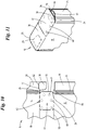
- Fig. 12 shows an expanded outer panel 14 as an alternative to Fig. 3 , While in the latter embodiment, the outer bottom wall 12 has a single layer is, exists according to Fig. 12 the bottom wall of an inner tab 63 which is connected to the outer rear wall 16 and an outer tab 64 adjacent to the outer front wall 15.
- the tabs 63, 64 are approximately equal in size, so that the bottom wall is formed double-ply overall.
- Fig. 16 and Fig. 18 are cross-sections of the pack, namely the one hand Fig. 1 (Cross section in Fig. 16 ) and on the other hand the Fig. 7 (Cross section in Fig. 18 ).
- the off-center, so offset lying opening aids each form a discharge opening 40 with four exposed cigarettes 10 (indicated by hatching).
- the position of the glue points 48 for connecting the tear-off tab 46 to the opening tab 41 is important.
- the respective glue spots 48 are arranged substantially in the region of a cigarette, so that they have a certain support when the opening tab 41 is pressed against the respective glue points 48 of the tear-off tab 46 form.
- a durable for the duration of use of the package connection is given - in particular by full-surface gluing - while the reclosing effective connection in the region of the edge strips 44th should have a relatively lower durability, namely the opening of the closure label 43 should allow easy removal of the same from the wall of the package.
- the blank 14 is provided over its entire surface with a coating on the outside (lacquer layer).
- This has a recess 65 in the region of the (glue) connection of the closure label 43 with increased strength.
- the closure label 43 preferably with a full-surface layer of glue, lies directly against the packaging material (cardboard, paper).
- this area is shown as hatched area.
- a permanently strong adhesive bond of the closure label 43 is provided with the outer panel 14. Outside the recess 15, namely in the region of the edge strips 44, the (more easily detachable) glue connection of the closure label 43 with the coating of the packaging material is provided.
- the surface 65 be prepared in other ways for a permanent (area) adhesion of the closure label 43, z. B. by an effective coating.
- All embodiments described above can also be designed in such a way that - waiving the connection between the outer package 12 and the inner pack 13 - connection of opening tab 41 and tear-off tab 46 - only the outer package 12 is opened, that receives a removal opening 40.
- the inner blank 32 then has to be opened by hand in the region of the removal opening 40 formed in order to remove cigarettes 10.
- FIGS. 20 to 25 show examples of a special design of this opening aid exclusively in the area of the outer end wall 18th Fig. 26 is the alternative training of the opening aid accordingly Fig. 2 ,
- this embodiment which is also analogous to the other examples described, only the opening tab 41 is connected to the closure label 43 (full surface) by gluing. By operating the closure label 43, the opening tab 41 is accordingly separated from the composite with the outer package 12. The inner pack 13 remains intact during this opening process and must be opened by a separate measure.
- the opening tab 41 is - as in the example of Fig. 2 - Designed so that in the region of transverse packing edges 50 between the outer end wall 18 on the one hand and outer front wall 15 or outer rear wall 16 on the other hand transverse line joints 68, 69 of the opening tab 41 are formed. These facilitate in particular the return of the opening tab 41 in the closed position while adapting to the contour of the outer package 12.
- the line joint 69 in the region of the rear edge of the package allows the pivotal movement of the opening tab 41st
- FIGS. 20 to 25 is the opening aid or the opening tab 41 exclusively in the region of the outer end wall 18, and arranged eccentrically on one side, analogous to the embodiments according to Fig. 10, Fig. 11 such as Fig. 17 ,
- the due to the Round corners 26 at the free edge tongue-shaped opening tab 41 corresponds to the width of the corresponding dimension of the outer end wall 18.
- the tongue-like end contour of the outer end wall 18 facilitates the initiation of the separation process when opening the package.
- a transverse line joint 69 allows - analogous to Fig. 26 - The pivoting movement of the opening tab 41 between closed and open position.
- the closure label 43 On the outside of the closure label 43 is attached, which as a strip-shaped structure preferably in the width of the outer end wall 18 in a partial area which is greater than the corresponding dimension of the opening tab 41, covers under permanent connection with the opening tab 41st Die VerInstitutetikett 43 has according to the contour of the outer end wall 18 curves 71.
- An actuating leg 72 extends on the associated outer side wall 23, in the width thereof, namely only in the (planar) area between the round edges 24, that is, with a smaller width than the closure label 43, moreover.
- At the free end of the (tongue-like, adhesive-free) grip tab 45 is formed. By detecting them, the shutter label 43 can be pulled to the open position shown in FIG. 21.
- the inner pack 13 remains closed in this embodiment.
- a special feature here is the formation of the blank for the outer package 12 ( Fig. 22 ). It lacks in this embodiment corner tabs on the side of the opening tab 41, so the example in Fig. 3 As a result, the region of a transverse edge of the outer end wall 18 remains without connection to the outer side wall 23.
- a cover is provided by the closure label 43, which covers a gap formed between outer end wall 18 and outer side wall 23 in the closed position , Incidentally, the blank ( Fig. 22 ) formed in the same manner as that according to Fig. 3 , It is also possible a design accordingly Fig. 12 ,
- an opening tab 41 of the outer pack 12 is also arranged exclusively in the region of the outer end wall 18, in the width thereof and with its contour.
- perforation lines 70 are arranged for the (lateral) delimitation of the opening tab 41.
- a transverse punched cut 73 delimits the opening tab 41 from the remaining part of the outer end wall 18.
- the closure label 43 extends over the full area of the opening tab 41 with a projection which forms the grip tab 45. Upon actuation of the closure label 43, this is therefore initially subtracted from the outer end wall 18. Then, the opening tab 41 is detected and separated along the perforation lines 70 from the connection with the outer package 12 - outer front wall 15 and outer rear wall 16 -.
- the opening tab 41 is connected as edge-side portion of the outer end wall 18 with the corner tabs 30, which may be formed in the same manner as the opposite corner tabs 29.
- the corner tabs 30 is connected to the inside or bottom of the outer end wall 18, (specifically) in the region of the opening tab 41, in particular by (three) glue points 31. These are in the production of the package on the inside of the blank ( Fig. 25 ) is arranged so that upon folding of the outer package 12 of the corner tabs 30 is connected to the outer end wall 18 and the opening tab 41.
- the opening tab 41 Upon actuation of the closure label 43 thus the opening tab 41 is pivoted while maintaining the connection with the corner tabs 30 about a common folding joint 74.
- a hinge connection between the opening tab 41 and the outer side wall 23 is provided.
- the inner package 13 may be formed or folded in different embodiments in these embodiments.
- Advantageous is an embodiment in which the Inner panel is folded over the cigarette group 11 in a conventional manner, such that a conventional end fold with trapezoidal end tabs 75 is formed, such as in a standard soft cup package.
- the opened outer pack 12 ( Fig. 21 . Fig. 24 ) allows access to the inner package 13, with the help of the front flap 75 manually the inner pack 13 can be opened.
- the material of the inner blank 32 is designed to be able to tear.
- this - and preferably a neighboring area of the inner front wall 33 - is provided with a line of weakness 76 (perforation).
- the weakening line 76 is preferably formed as in FIG Fig. 13 or according to Fig. 14 , ie in each case with a transverse tear line 51, that is to say a continuous punching line, for facilitating the detection of the manually openable tear-off tab 46 of the inner pack 13.
- cigarette packs according to FIGS. 20 to 26 can be formed by appropriate punches in the outer package 12 so that - waiving a closure label 43 - the opening tab 41 is operated in the region of a correspondingly designed detection edge directly by hand and pulled into the open position.
- Cigarette 47 weakening line 11 cigarette group 48 spot of glue 12 overpack 49 tear-off edge 13 interior package 50 fold 14 outer panel 51 tear line 15 Outside front wall 52 fold line 16 An exterior rear wall 53 handle tongue 17 Exterior floor wall 54 cross perforation 18 Exterior front wall 55 transverse edge 19 outer side lobe 56 parting line 20 inner side lobe 57 centerpiece 21 spot of glue 58 counterpart 22 Exterior side wall 59 counterpart 23 Exterior side wall 60 perforating 24 round edge 61 grip 25 groove 62 Cross punch 26 rounded corner 63 inner flap 27 connecting tabs 64 outer flap 28 spot of glue 65 recess 29 corner tabs 66 neckline 30 corner tabs 67 chad 31 spot of glue 68 line joint 32 inner blank 69 line joint 33 Interior front wall 70 perforation 34 Inner rear wall 71 curve 35 Inside front wall 72 actuating leg 36 base tabs 73 chad 37 base tabs 74 folding joint 38 wall tabs 75 frontal lobe 39 wall tabs 76 weakening line 40 removal opening 41 opening tab 42 weaken
Landscapes
- Engineering & Computer Science (AREA)
- Mechanical Engineering (AREA)
- Packaging Of Annular Or Rod-Shaped Articles, Wearing Apparel, Cassettes, Or The Like (AREA)
- Cartons (AREA)
- Packages (AREA)
Description
- Die Erfindung betrifft Zigarettenpackungen mit den Merkmalen des Oberbegriffs des Anspruchs 1.
- Eine nach dem Konzept einer Weichbecherpackung ausgebildete Zigarettenpackung mit einem mehrfach benutzbaren Verschluss einer Innenpackung ist bekannt durch
WO 2012/007081 A1 . Bei dieser Zigarettenpackung ist eine Außenpackung becherförmig ausgebildet, also oben offen. Eine Innenpackung besteht aus einem eine Zigarettengruppe umgebenden Innenzuschnitt aus Stanniol. Der mehrfach benutzbare Verschluss besteht aus einem Klebeetikett, welches sich über die Stirnseite der Packung erstreckt und flächig mittels lösbarem Kleber an der Außenpackung einerseits und der Innenpackung andererseits fixiert ist. Letztere weist im Bereich einer Ausnehmung der Vorderwand der Außenpackung eine durch Schwächungslinien definierte Abrisslasche auf. Diese wird aufgrund der Verbindung mit dem Klebeetikett beim Öffnen der Packung unter Bildung einer Entnahmeöffnung aus der Verbindung mit dem Innenzuschnitt herausgetrennt. Faltlappen des Innenzuschnitts bleiben bei geöffneter Packung in der Faltebene, nämlich in der Ebene der Stirnwand. Darüber hinaus ist die Packung im Bereich der Öffnung komplex ausgebildet und nicht ausreichend stabil. - Weiterhin ist eine Zigarettenpackung bekannt, bei der die Innenpackung als Dichtpackung ausgebildet ist mit einer die Zigarettengruppe umgebenden, thermisch siegelbaren und feuchtigkeitsdichten Folie. Diese bildet seitliche Flossennähte und eine Quernaht. Eine mehrfach benutzbare Öffnungshilfe ist im Bereich der Innenpackung als Öffnungslasche ausgebildet, die sich über die Breite der Stirnwand und über einen stirnseitigen Bereich der Vorderwand erstreckt. Ein Endstück der Lasche ist mit Leimpunkten an einer Innenlage der Innenpackung in Schließstellung fixierbar. Die Außenpackung ist nach Art einer Faltpackung mit Verschlusslasche ausgebildet, die sich über die Stirnseite und einen oberen Bereich der Frontseite erstreckt. Die Öffnungslasche der Innenpackung ist mit der Verschlusslasche verbunden, wird also mit dieser betätigt beim Öffnen und Schließen. Diese Packung ist hinsichtlich des einzusetzenden Materials und hinsichtlich der Konstruktion aufwendig und komplex. Die Fertigung einer derartigen Packung ist schwierig (
EP 2 455 302 A1 ). - Der Erfindung liegt die Aufgabe zugrunde, eine Zigarettenpackung vorzuschlagen, die eine erhöhte Formstabilität aufweist und einen einfach und zuverlässig handhabbaren Öffnungsmechanismus. Darüber hinaus soll die Packung auf (herkömmlichen) Packern leistungsfähig produziert werden können.
Zur Lösung dieser Aufgabe ist die erfindungsgemäße Packung mit den Merkmalen des Anspruchs 1 ausgebildet.
Die Außenpackung ist im Bereich einer geschlossenen Stirnwand mit einer definierten Öffnungslasche versehen. Diese ist in Schließstellung von einem Betätigungs- oder Verschlussetikett überdeckt. Beim Abziehen desselben von der Außenpackung wird aufgrund der Klebeverbindung die Öffnungslasche aus dem Verbund mit dem Zuschnitt der Außenpackung herausgetrennt und in die Öffnungsstellung geführt, wobei aufgrund der Ausbildung und Anordnung der Öffnungslasche die gebildete Entnahmeöffnung der Außenpackung ausschließlich im Bereich der Stirnwand gebildet ist.
Die Innenpackung ist im Bereich der Entnahmeöffnung mit einem korrespondierenden, teilweise abtrennbaren Gegenstück zur Öffnungslasche der Außenpackung versehen, nämlich mit einer Abrisslasche des Innenzuschnitts. Diese ist so angebracht und mit der Öffnungslasche verbunden, dass stets eine Einheit aus entsprechenden Teilstücken des Außenzuschnitts und des Innenzuschnitts in die Öffnungsstellung gebracht werden, derart, dass Innenpackung und Außenpackung die Entnahmeöffnung ausschließlich im Bereich der Stirnwand aufweisen.
Die Öffnungslasche einerseits und die Abrisslasche andererseits sind im Bereich geschlossener Wandungen der Außenpackung und der Innenpackung gebildet. Besonders geeignet ist ein Zuschnitt der Außenpackung, bei der die Außen-Stirnwand frei von Faltlappen ist - mit Ausnahme von Ecklappen. Der Zuschnitt der Innenpackung ist zweckmäßigerweise analog ausgebildet, nämlich vorzugsweise mit einer geschlossenen Innen-Stirnwand ohne Faltlappen in diesem Bereich, wobei die Fertigung des Zigarettenblocks so abläuft, dass die Zigarettengruppe mit ihren Filtern in Transportrichtung vorn liegend dem Zuschnitt zugeführt werden.
Die Außenpackung besteht aus einem reißfähigen Verpackungsmaterial, also insbesondere dünnem Karton, Papier oder vorzugsweise aus einem Rigid-Soft-Verpackungsmaterial (Papier mit einem Gewicht von 135 g/m2 bis 150 g/m2). Der Innenzuschnitt besteht aus Papier, Stanniol oder (reißfähiger) Folie.
Weitere Einzelheiten der erfindungsgemäßen Packung werden nachfolgend anhand der Patentzeichnungen erläutert, wobei die erfindungsgemäßen Merkmale inFig. 4 und Fig. 5 sowie inFig. 14 dargestellt sind. Es zeigt: -
Fig.1 eine geschlossene (Zigaretten-)Packung in perspektivischer Darstellung, die nicht ein Teil der Erfindung ist, -
Fig. 2 einen stirnseitigen (oberen) Bereich der Packung gemäßFig. 1 in geöffneter Stellung, ebenfalls in Perspektive, -
Fig. 3 einen ausgebreiteten Zuschnitt für die Packung gemäßFig. 1 , Fig. 2 , nämlich für die Außenpackung, -
Fig. 4 einen Ausschnitt eines Zuschnitts gemäßFig. 3 mit veränderten Details, in vergrößertem Maßstab, gemäß der Erfindung f -
Fig. 5 eine Darstellung entsprechendFig. 2 aus einem Zuschnitt gemäßFig. 4 , f -
Fig. 6 eine weitere Alternative eines Zuschnitts für die Außenpackung als Ausschnitt, die nicht ein Teil der Erfindung ist, Die Ausführungsformen derFig.7-13 und15-26 sind nicht ein Teil der Erfindung. -
Fig. 7 einen stirnseitigen Bereich einer Packung unter Einsatz eines Zuschnitts gemäßFig. 6 , -
Fig. 8 eine Einzelheit analogFig. 4 ,Fig. 6 für ein weiteres Ausführungsbeispiel einer Packung, -
Fig. 9 einen stirnseitigen Bereich einer Packung aus einem Zuschnitt gemäßFig. 8 in Perspektive, -
Fig. 10 eine Einzelheit analogFig. 8 für ein weiteres Ausführungsbeispiel, -
Fig. 11 einen stirnseitigen Bereich einer Packung auf der Grundlage eines Zuschnitts gemäßFig. 10 , in Perspektive, -
Fig. 12 eine Alternative zuFig. 3 , nämlich eines Zuschnitts für eine Außenpackung, -
Fig. 13 einen ungefalteten Zuschnitt für eine Innenpackung, -
Fig. 14 eine Einzelheit eines Zuschnitts für eine Innenpackung im Bereich einer Entnahmeöffnung, in vergrößertem Maßstab, gemäß der Erfindung, -
Fig. 15 eine Einzelheit entsprechendFig. 14 für ein weiteres Ausführungsbeispiel, -
Fig. 16 einen Querschnitt durch eine Packung entsprechend Schnittebene XVI-XVI inFig. 1 , -
Fig. 17 die Packung gemäßFig. 11 in geöffnetem Zustand mit versetzt gezeigtem Abtrennteil, -
Fig. 18 einen Querschnitt XVIII-XVIII derFig. 7 , -
Fig. 19 eine Einzelheit eines Zuschnitts für eine Außenpackung im Bereich der Entnahmeöffnung, -
Fig. 20 eine weitere abgeänderte Ausführung einer geschlossenen (Zigaretten-)Packung in perspektivischer Darstellung, -
Fig. 21 einen stirnseitigen Bereich der Packung gemäßFig. 20 in Öffnungsstellung, -
Fig. 22 einen ungefalteten Zuschnitt für eine Außenpackung fürFig. 20 bzw. 21, -
Fig. 23 eine nochmals geänderte Ausführung einer Packung in einer Darstellung analogFig. 20 , -
Fig. 24 die Packung gemäßFig. 23 in Öffnungsstellung, -
Fig. 25 einen Zuschnitt für eine Außenpackung, geeignet fürFig. 23, Fig. 24 , -
Fig. 26 einen stirnseitigen Bereich einer weiteren Ausführung einer Packung in Öffnungsstellung. - Die in den Zeichnungen dargestellten, im Wesentlichen quaderförmigen Packungen dienen zur Aufnahme einer Gruppe von Zigaretten 10. Die Abmessungen der Packungen sind so gewählt, dass Zigarettengruppen 11 mit in drei Reihen geordneten Zigaretten 11 Aufnahme finden können (
Fig. 16 ,Fig. 18 ). Die Packung besteht mindestens aus einer Außenpackung 12 und einer Innenpackung 13. Weiterhin kann die Packung mit einer (herkömmlichen) Außenumhüllung aus Cello oder Kunststofffolie versehen sein (nicht gezeigt). - Die Außenpackung 12 besteht aus einem Außenzuschnitt 14 aus faltbarem Verpackungsmaterial, insbesondere dünnem Karton, Papier oder Rigid-Soft-Verpackungsmaterial. Der Außenzuschnitt 14 ist so ausgebildet, dass der Packungsinhalt, also die Innenpackung 13, vollständig und allseitig umschlossen ist. Der Außenzuschnitt 14 bildet demnach eine Außen-Vorderwand 15, eine Außen-Rückwand 16, eine Außen-Bodenwand 17 und eine Außen-Stirnwand 18. Weiterhin sind im Bereich von Vorderwand 15 und Rückwand 16 Seitenlappen angeordnet, nämlich äußere Seitenlappen 19 an der Vorderwand 15 und innere Seitenlappen 20 an der Rückwand 16. Die Seitenlappen 19 und 20 sind bei der fertigen Packung durch Leim - Leimpunkte 21 am äußeren Seitenlappen 19 - miteinander verbunden und bilden Außen-Seitenwände 22, 23 der fertigen Packung.
- Eine Besonderheit besteht darin, dass aufrechte Packungskanten als Rundkanten 24 ausgebildet sind, also im Querschnitt viertelkreisförmig, etwa entsprechend der Abmessung einer Zigarette 10. Die Rundkanten 24 sind durch eine Gruppe von parallelen Rillen 25 des Außen-Zuschnitts 14 definiert. Die Außen-Bodenwand 17 und die Außen-Stirnwand 18 sind mit entsprechend ausgebildeten Rundecken 26 versehen.
- Der Außenzuschnitt 14 ist nach dem Längsfaltprinzip aufgebaut, jedoch mit einer besonderen Reihenfolge der Wandungen. Zwischen der Außen-Vorderwand 15 und der Außen-Rückwand 16 befindet sich die Außen-Stirnwand 18. Diese ist demnach frei von Verbindungslappen. Die Außen-Bodenwand 17 schließt an das freie Ende der Außen-Rückwand 16 an. Am freien Rand der Außen-Bodenwand 17 ist ein - trapezförmiger - Verbindungslappen 27 angebracht. Dieser liegt bei der fertigen Packung an der Innenseite der Außen-Vorderwand 15 an und ist mit dieser verbunden, vorliegend durch (drei in Reihe angeordnete) Leimpunkte 28. Ecklappen 29, 30 dienen zur Verbindung der Außen-Seitenwände 22, 23 mit der Bodenwand 17 bzw. Stirnwand 18. Die Ecklappen 29, 30 liegen an der Innenseite der Bodenwand 17 und der Stirnwand 18 an und sind dort jeweils mittels Leim (zwei Leimpunkte 31) fixiert.
Die Innenpackung 13 aus einem Innenzuschnitt 32 (Fig. 13 ) ist hinsichtlich der Gestaltung auf die Außenpackung 12 abgestimmt. Der Innenzuschnitt 32 besteht aus dünnem, faltbarem Packstoff, nämlich Papier, Stanniol oder Folie. Durch Faltlinien sind Innen-Vorderwand 33, Innen-Rückwand 34 und zwischen diesen angeordnete Innen-Stirnwand 35 nach dem Längsfaltprinzip aufeinanderfolgend definiert. An den Enden von Vorderwand 33 und Rückwand 34 befinden sich Bodenlappen 36, 37, die durch entsprechende Faltung und bei wechselseitiger Überlappung eine Innen-Bodenwand bilden. Auch Innen-Seitenwände werden aus seitlichen Wandlappen 38, 39 gebildet und überdecken einander teilweise in Faltstellung (Fig. 16 ,Fig. 18 ). Die aus diesem Innenzuschnitt 32 gebildete Innenpackung 13 liegt mit der ohne Faltlappen ausgebildeten, geschlossenen Innen-Stirnwand 35 an der Innenseite der Außen-Stirnwand 18 an.
Eine Besonderheit der Packung besteht in einer Öffnungshilfe. Diese kann für einen mehrmaligen Öffnungs- und Schließvorgang oder für einen einmaligen Öffnungsvorgang ausgebildet sein. Weiterhin kann die Öffnungshilfe alternativ so gestaltet sein, dass bei Betätigung derselben eine Entnahmeöffnung 40 im Bereich von Außenpackung 12 und Innenpackung 13 gleichzeitig oder lediglich eine Öffnung im Bereich der Außenpackung 12 geschaffen wird. Im letztgenannten Falle muss die Innenpackung 13 durch den Verbraucher (manuell) geöffnet werden.
Bei dem Ausführungsbeispiel gemäßFig. 1 bis Fig. 3 in Verbindung mitFig. 13 ist die Öffnungshilfe im Bereich der Außen-Stirnwand 18 angeordnet, quer zu dieser. Es entsteht so eine (längliche, rechteckige) Entnahmeöffnung 40, die sich über die volle Breite bzw. Tiefe der Stirnwand 18 erstreckt und mit einem Schenkel in den Bereich der Vorderwand 15 fortgesetzt ist. Die Entnahmeöffnung 14 wird durch besonderes Zusammenwirken von Außenpackung 12 und Innenpackung 13 geschaffen. Der Außenzuschnitt 14 ist mit einer der Entnahmeöffnung 40 entsprechenden Öffnungslasche 41 versehen. Diese ist als Teil des Außenzuschnitts 14 ausgebildet und durch eine Schwächungslinie 42 begrenzt, bei der es sich vorzugsweise um eine Perforationslinie handelt. Diese ist im Wesentlichen U-förmig ausgebildet, mit der offenen Seite im Bereich der Außen-Rückwand 16. Beim Öffnen der Packung wird die Öffnungslasche 41 aus dem Verbund mit dem Außenzuschnitt 14 entlang der Schwächungslinie 42 herausgetrennt. Aufgrund der Ausbildung der Schwächungslinie 42 bleibt jedoch die Öffnungslasche 41 in Verbindung mit dem Außenzuschnitt 14, und zwar mit einem Schenkel der Rückwand 16. - Die Öffnungslasche 41 wird durch ein Hilfsmittel in die Öffnungsstellung bewegt, insbesondere durch ein Verschlussetikett 43. Dieses besteht aus Folie und ist durch Klebung mit der Außenseite des Außenzuschnitts 14 verbunden. Das Verschlussetikett 43 ist - als gesonderter Zuschnitt - so ausgebildet, dass die Öffnungslasche 41 komplett überdeckt ist unter Bildung eines ringsherum laufenden Randstreifens 44. Dieser ist mit einem Bereich des Außenzuschnitts 14 neben der Schwächungslinie 42 verbunden. Wenn nach erstmaligem Öffnen der Packung das Verschlussetikett 43 entlang der Schwächungslinie 42 aus dem Zuschnitt herausgetrennt ist, bildet der klebende Randstreifen 44 des Verschlussetiketts 43 beim Wiederverschließen der Packung eine haltbare Schließstellung. An einem freien Rand ist das Verschlussetikett mit einer leimfreien Grifflasche 45 versehen.
- Die Öffnungshilfe bzw. das Verschlussetikett 43 ist seitlich versetzt zu einer gedachten mittleren Querebene der Stirnwand 18 angeordnet. Der auf dieser Seite liegende Ecklappen 13 ist entsprechend verkürzt, sodass in der Faltstellung der Ecklappen außerhalb des Bereichs der Entnahmeöffnung 40 liegt (
Fig. 2 ). - Die Innenpackung 13 bzw. deren Innenzuschnitt 32 ist mit einem zur Bildung der Entnahmeöffnung 40 heraustrennbaren Zuschnittbereich versehen, insbesondere mit einer Abrisslasche 46. Diese ist hinsichtlich der Position bzw. Relativstellung innerhalb des Innenzuschnitts 32, hinsichtlich Größe und/oder Kontur auf die Öffnungslasche 41 des Außenzuschnitts 14 abgestimmt. Die Abrisslasche 46 ist durch eine Schwächungslinie 47, insbesondere durch eine Perforationslinie in dem Material des Innenzuschnitts definiert, derart, dass beim Betätigen der Öffnungshilfe die Abrisslasche 46 zeitgleich ganz oder teilweise aus der Verbindung mit dem Innenzuschnitt 32 herausgetrennt wird.
- Der (komplett dargestellte) Innenzuschnitt 32 gemäß
Fig. 13 ist mit einer im Wesentlichen rechteckigen Abrisslasche 46 versehen, die sich quer über die Innen-Stirnwand 35 erstreckt, und zwar in einer auf die Öffnungslasche 41 des Außenzuschnitts 14 ausgerichteten Relativstellung. Die Anordnung ist so gewählt, dass die Abrisslasche 46 in den Abmessungen geringfügig kleiner ist als die Öffnungslasche 41, sodass auch bei geringfügigen Fertigungstoleranzen die Abrisslasche 46 vollständig innerhalb des Bereichs der Öffnungslasche 41 liegt. Bei dem Beispiel derFig. 13 ist die Abrisslasche 46 von einer geschlossenen, ringsherum laufenden Schwächungslinie 47 begrenzt. - Eine Besonderheit besteht darin, dass die Abrisslasche 46 als Teil der Innenpackung 13 (dauerhaft) mit der Öffnungslasche 41 der Außenpackung 12 verbunden ist. Die überwiegende Fläche der Abrisslasche 46, mindestens im Bereich der Innen-Vorderwand 33 sowie der Innen-Stirnwand 35 ist durch Leim mit der Innenseite der Öffnungslasche 41 verbunden. Bei dem vorliegenden Ausführungsbeispiel sind mehrere Leimpunkte 48 verteilt angeordnet, insbesondere in Eckbereichen der Abrisslasche 46 bzw. der abtrennbaren Schenkel derselben.
- Durch die Funktionseinheit von Öffnungslasche 41 und Abrisslasche 46 wird bei einer Betätigung der Öffnungslasche 41 - bei dem Ausführungsbeispiel gemäß
Fig. 1 bis Fig. 3 durch das Verschlussetikett 43 - Materialstücke aus der Außenpackung 12 und aus der Innenpackung 13 zeitgleich unter Bildung der Entnahmeöffnung 14 herausgetrennt. Bei dem vorgenannten Ausführungsbeispiel können diese Zuschnittteile 41, 46 mit Hilfe des Verschlussetiketts 43 in die Schließstellung zurückgeführt werden.Fig. 4, Fig. 5 offenbart eine Öffnungshilfe gemäß der Erfindung. Der prinzipielle Aufbau mit Öffnungslasche 41 und Abrisslasche 46 und vorzugsweise mit Verschlussetikett 43 entspricht dem beschriebenen Ausführungsbeispiel. Die Öffnungslasche 41 der Außenpackung 12 ist vorliegend nur im Bereich der Außen-Stirnwand 18 positioniert und erstreckt sich mit einem Abschnitt bzw. Schenkel in die Außen-Rückwand 16 (Fig. 4 ). Eine (frontseitige) Abrisskante 49 der Öffnungslasche 41 läuft entlang einer Faltkante 50 zwischen Außen-Vorderwand 15 und Außen-Stirnwand 18. Die Schwächungslinie 42 ist in diesem Bereich - wie auch bei dem Ausführungsbeispiel derFig. 3 - mit einem längeren, quergerichteten Stanzschnitt ausgebildet, sodass die Mitnahme der Öffnungslasche 41 durch das Verschlussetikett 43 beim erstmaligen Öffnen gewährleistet ist. Der wirksame Bereich der Öffnungslasche 41 erstreckt sich über die Breite bzw. Tiefe der Außen-Stirnwand 18, sodass auch die gebildete Entnahmeöffnung ausschließlich im Bereich der Außen-Stirnwand 18 liegt. Das Verschlussetikett 43 erstreckt sich mit einem (längeren) Schenkel bis in die Außen-Vorderwand 15. Hier liegt auch die Grifflasche 45.
Die Innenpackung 13 bzw. der Innenzuschnitt 32 ist auf die Gestaltung der Öffnungshilfe ausgerichtet. Vorzugsweise ist der Innenzuschnitt 32 im Bereich der Öffnungshilfe entsprechendFig. 14 ausgebildet. Die Abrisslasche 46 erstreckt sich im Bereich der Innen-Stirnwand 35 mit einer quergerichteten Reißlinie 51 entlang einer die Innen-Stirnwand 35 begrenzenden Faltlinie 52. Ein kurzer Schenkel der Abrisslasche 46 liegt in der Innen-Rückwand 34.
Die so ausgebildete Abrisslasche 46 ist in ihrer Position im Wesentlichen mittig auf die Öffnungslasche 41 gemäßFig. 4, Fig. 5 ausgerichtet und mit dieser haltbar verbunden durch (vier) Leimpunkte 48. Die Einheit aus Öffnungslasche 41 und Abrisslasche 46 wird gemeinsam in die Öffnungsstellung geführt - mit dem Verschlussetikett 43. Die Öffnungslasche 41 und Abrisslasche 46 können durch entgegengesetzte Betätigung in die Schließstellung zurückgeführt werden. - Die Öffnungshilfe kann alternativ, aber nicht gemäß der Erfindung, auch ohne Verschlussetikett ausgebildet sein. Bei dieser Dabei ist die Öffnungslasche 41 so ausgebildet und/oder angeordnet, dass ein Teilstück bzw. ein Randbereich der Öffnungslasche 41 unmittelbar erfasst und danach die Einheit aus Öffnungslasche 41 und Abrisslasche 46 in die Öffnungsstellung gebracht werden kann.
- Bei dem Ausführungsbeispiel gemäß
Fig. 6, Fig. 7 ist durch eine vorzugsweise geschlossene Schwächungslinie 42 bzw. Perforationslinie ein (rechteckiger) Bereich als Öffnungslasche 41 der Außen-Stirnwand 18 angeordnet. Die Stanzung der Linie 42 ist so ausgebildet, dass an einer Querseite - vorliegend an der der Außen-Vorderwand 15 zugekehrten Seite - ein durchgehender Stanzschnitt 67 angeordnet ist. Aufgrund von bogenförmigen Enden der Stanzung 67 entsteht eine schmale Griffzunge 53 der Öffnungslasche 41. Die Anordnung ist so getroffen, dass die Griffzunge 53 bzw. die dieser zugeordnete Stanzung 67 im Bereich einer benachbarten Wandung des Außenzuschnitts 14 angeordnet ist, vorliegend im Bereich der Außen-Vorderwand 15. Durch die Faltung des Zuschnitts 14 entlang der stirnseitigen Faltkante 50 wird aufgrund der Rückstellkräfte im Material die Griffzunge 53 in einer Winkel- bzw. Schrägstellung zur Vorderwand 15 positioniert (Fig. 7 ). Die Griffzunge 53 ist dadurch leicht erfassbar. Die Öffnungslasche 41 kann sodann in eine Öffnungsstellung bewegt werden, vorzugsweise unter Heraustrennen aus der Außen-Stirnwand 18. - Der Innenzuschnitt 32 kann hinsichtlich der Anordnung und Ausgestaltung der Abrisslasche 46 entsprechend
Fig. 14 ausgebildet sein. Durch Verklebung wird die Einheit aus Öffnungslasche 41 und Abrisslasche 46 hergestellt, die aus Innenpackung 13 und Außenpackung 12 vollständig entfernt wird, und zwar aufgrund einer Querperforation 54 der Öffnungslasche 41 gegenüberliegend zur Griffzunge 53, vorliegend am oberen Rand der Außen-Rückwand 16. Es entsteht so eine freie Entnahmeöffnung, die nicht wieder verschlossen wird. - Der Außenzuschnitt 14 kann alternativ so ausgebildet sein, dass in räumlicher Nachbarschaft zur Öffnungslasche 41 liegende Zuschnittteile aufgrund einer (besonderen) Ausbildung und/oder Faltstellung das Erfassen der Öffnungslasche beim (erstmaligen) Öffnen ermöglichen. Bei der Ausführung gemäß
Fig. 8, Fig. 9 dient eine Randkante einer Wand der Außenpackung 12 als Betätigungsmittel für die Öffnungslasche 41. Diese ist aufgrund entsprechender Schwächungslinie in den Randbereich bzw. an einer Seite der Außen-Stirnwand 18 angeordnet. Eine freie Querkante 55 der Außen-Stirnwand 18 bildet aufgrund entsprechender Gestaltung des Außenzuschnitts einen erfassbaren freien Vorsprung zur Betätigung der Öffnungslasche 41. Die Außen-Stirnwand 18 mit der Querkante 55 ragt aufgrund entsprechender Gestaltung des Außenzuschnitts 14 geringfügig über die Kontur der Außenpackung 12 bzw. über die Außen-Seitenwand 23 hinweg. Die Öffnungslasche 41 wird demnach unmittelbar erfasst und entlang der Schwächungslinie 42 als Teilstück der Außen-Stirnwand 18 abgetrennt. - Die in der beschriebenen Weise mit der Öffnungslasche 41 verbundene Abrisslasche 46 wird gleichzeitig mit angehoben. Der an dieser Seite der Stirnwand 18 liegende Ecklappen 30 wird beim Öffnen der Lasche 41 mit angehoben. Zu diesem Zweck ist der Ecklappen 30 von dem zugeordneten Seitenlappen 20 abtrennbar. Eine Trennlinie 56 ist als Schwächungslinie ausgebildet, insbesondere mit Stanzungen und Restverbindungen.
- Die Öffnungslasche 41 ist bei dem Ausführungsbeispiel
Fig. 8, Fig. 9 in besonderer Weise ausgebildet. Ein im Wesentlichen rechteckiges Mittelstück 57 erstreckt sich innerhalb der Außen-Stirnwand 18. Diese ist demnach Teil der Öffnungslasche 41. An einer, vorliegend an beiden Seiten sind Seitenstücke 58, 59 durch die entsprechend konturierte Schwächungslinie 42 angeordnet, dies als Teil der Vorderwand 15 einerseits und der Rückwand 16 andererseits ausgebildet sind. Ein schräg verlaufender Perforationsabschnitt 60 ermöglicht den Trennvorgang im Bereich von Vorderwand 15 und Rückwand 16, sodass die Seitenstücke 58, 59 eine trapezförmige Kontur aufweisen. Entsprechend ist die (dauerhafte) Entnahmeöffnung ausgebildet. Obere Enden der Zigaretten 10 liegen im Bereich von Vorderwand 15 und/oder Rückwand 16 frei. - Der Innenzuschnitt 32 ist hinsichtlich der Gestalt der Abrisslasche (nicht gezeigt) an die Kontur der Öffnungslasche 41 in
Fig. 8, Fig. 9 angepasst. Die Anzahl und Positionierung der Leimpunkte 48 berücksichtigt den Seitenstücken 58, 59 der Öffnungslasche 41 zugeordnete Bereiche der Abrisslasche. - Bei dem Ausführungsbeispiel der
Fig. 10, Fig. 11 - ohne Verschlussetikett - dient ein Teil des Außenzuschnitts 14 als Mittel zur Betätigung der Öffnungslasche 41. Diese ist beispielshaft als (rechteckiges) End- bzw. Seitenstück der Stirnwand 18 ausgebildet. Aufgrund einer geschlossenen Schwächungs- bzw. Perforationslinie 42 wird eine Öffnungslasche 41 definiert, deren Breite der entsprechenden Abmessung der Außen-Stirnwand 18 entspricht und deren Länge vorzugsweise etwa der halben Länge der Stirnwand 18 entspricht. Die Öffnungslasche 41 mit Abrisslasche 46 wird bei der erstmaligen Betätigung entfernt. - Die Betätigung der Öffnungslasche 41 bei Ingebrauchnahme der Packung erfolgt über ein Griffstück 61, welches über die Kontur der Stirnwand 18, also über deren Querkante 55 hinweg ragt. Das Griffstück 61 ist Teil des entsprechend ausgebildeten Ecklappens 30. Dieser ist mit einer Querstanzung 62 mit bogenförmigen Enden versehen. In der Faltstellung - Anlage des Ecklappens 30 an der Innenseite der Stirnwand 18 - wird das Griffstück 61 aufgrund der Querstanzung 62 nach außen gerichtet. Die Abmessungen sind so gewählt, dass das Griffstück 61 einen nach außen gerichteten Überstand bildet. Das zungenförmige Griffstück 61 befindet sich im Bereich eines Ausschnitts 66, der durch entsprechende Verkürzung des äußeren Seitenlappens 19 (
Fig. 10 ) geschaffen ist. - Die Schwächungslinie 42 schließt an die Enden der Querkante 55 bzw. an die Rundecken 26 der Stirnwand 18 an und bilden so eine Fortsetzung der Wandkante, sodass das Abtrennen der Öffnungslasche 41 erleichtert ist.
- Die Innenpackung 13 bzw. deren Innenzuschnitt 32 ist im Bereich der Abrisslasche 46 vorzugsweise entsprechend der Darstellung in
Fig. 15 ausgebildet. Die durch die Schwächungslinie 47 bzw. Perforation umschlossene Abrisslasche 46 ist mindestens im Bereich von Innen-Vorderwand 33 und Innen-Rückwand 34 größer ausgebildet, nämlich durch versetzte Anordnung der Schwächungslinie 47, als das Verschlussetikett 43. Beim Abtrennen desselben wird die mit der Öffnungslasche 41 verbundene Abrisslasche 46 als haubenförmiges Gebilde abgetrennt, sodass im Bereich der Entnahmeöffnung 40 der Trennrand des Innenzuschnitts 32 gegenüber dem Trennrand der Öffnungslasche 41 zurückgesetzt ist (Fig. 17 ). -
Fig. 12 zeigt einen ausgebreiteten Außenzuschnitt 14 als Alternative zuFig. 3 . Während bei der letztgenannten Ausführung die Außen-Bodenwand 12 einlagig ist, besteht gemäßFig. 12 die Bodenwand aus einem Innenlappen 63, der mit der Außen-Rückwand 16 verbunden ist und aus einem Außenlappen 64 im Anschluss an die Außen-Vorderwand 15. Die Lappen 63, 64 sind annähernd gleich groß, sodass die Bodenwand insgesamt doppellagig ausgebildet ist. - Eine weitere Besonderheit der Packung ist in
Fig. 16 undFig. 18 zu sehen. Es handelt sich dabei um Querschnitte der Packung, nämlich einerseits derFig. 1 (Querschnitt inFig. 16 ) und andererseits derFig. 7 (Querschnitt inFig. 18 ). Die außermittig, also versetzt liegenden Öffnungshilfen bilden jeweils eine Entnahmeöffnung 40 mit vier frei liegenden Zigaretten 10 (durch Schraffur gekennzeichnet). Weiterhin ist von Bedeutung die Position der Leimpunkte 48 zur Verbindung der Abrisslasche 46 mit der Öffnungslasche 41. Die betreffenden Leimpunkte 48 sind im Wesentlichen im Bereich einer Zigarette angeordnet, sodass diese eine gewisse Abstützung beim Andrücken der Öffnungslasche 41 an die betreffenden Leimpunkte 48 der Abrisslasche 46 bilden. - Schließlich ist die Besonderheit gemäß
Fig. 19 hervorzuheben. Bei Ausführungen der Packung mit einem Verschlussetikett 43 ist vorgesehen, dass zwischen dem Verschlussetikett 43 und der Öffnungslasche 41 eine für die Dauer der Benutzung der Packung haltbare Verbindung gegeben ist - insbesondere durch vollflächige Klebung -, während die beim Wiederverschließen wirksame Verbindung im Bereich der Randstreifen 44 eine relativ geringere Haltbarkeit aufweisen soll, nämlich beim Öffnen des Verschlussetiketts 43 ein leichtes Abziehen desselben von der Wandung der Packung ermöglichen soll. - Der Zuschnitt 14 ist vollflächig an der Außenseite mit einer Beschichtung versehen (Lackschicht). Diese weist im Bereich der (Leim-)Verbindung des Verschlussetiketts 43 mit erhöhter Festigkeit eine Aussparung 65 auf. In diesem Bereich liegt demnach das Verschlussetikett 43 mit vorzugsweise vollflächiger Leimschicht unmittelbar am Verpackungsmaterial (Karton, Papier) an. In
Fig. 19 ist dieser Bereich als schraffierte Fläche ausgewiesen. Hier wird eine dauerhaft starke Haftverbindung des Verschlussetiketts 43 mit dem Außenzuschnitt 14 geschaffen. Außerhalb der Aussparung 15, nämlich im Bereich der Randstreifen 44, ist die (leichter lösbare) Leimverbindung des Verschlussetiketts 43 mit der Beschichtung des Verpackungsmaterials gegeben. Alternativ kann die Fläche 65 auf andere Weise für eine dauerhafte (flächige) Haftung des Verschlussetiketts 43 vorbereitet sein, z. B. durch eine wirksame Beschichtung. - Alle vorstehend beschriebenen Ausführungsbeispiele können auch in der Weise ausgebildet sein, dass - unter Verzicht auf die Verbindung zwischen der Außenpackung 12 und der Innenpackung 13 - Verbindung von Öffnungslasche 41 und Abrisslasche 46 - lediglich die Außenpackung 12 geöffnet wird, also eine Entnahmeöffnung 40 erhält. Der Innenzuschnitt 32 muss dann im Bereich der gebildeten Entnahmeöffnung 40 von Hand geöffnet werden, um Zigaretten 10 zu entnehmen.
-
Fig. 20 bis Fig. 25 zeigen Beispiele für eine besondere Ausbildung dieser Öffnungshilfe ausschließlich im Bereich der Außen-Stirnwand 18.Fig. 26 ist die alternative Ausbildung der Öffnungshilfe entsprechendFig. 2 . Bei dieser Ausführung, die auch analog für die weiteren beschriebenen Beispiele in Betracht kommt, ist lediglich die Öffnungslasche 41 mit dem Verschlussetikett 43 (vollflächig) durch Klebung verbunden. Durch Betätigen des Verschlussetiketts 43 wird demnach die Öffnungslasche 41 aus dem Verbund mit der Außenpackung 12 herausgetrennt. Die Innenpackung 13 bleibt bei diesem Öffnungsvorgang unversehrt und muss durch eine gesonderte Maßnahme geöffnet werden. - Die Öffnungslasche 41 ist - wie bei dem Beispiel der
Fig. 2 - so ausgebildet, dass im Bereich von quergerichteten Packungskanten 50 zwischen der Außen-Stirnwand 18 einerseits und Außen-Vorderwand 15 oder Außen-Rückwand 16 andererseits quergerichtete Liniengelenke 68, 69 der Öffnungslasche 41 gebildet sind. Diese erleichtern insbesondere die Rückführung der Öffnungslasche 41 in die Schließstellung unter Anpassung an die Kontur der Außenpackung 12. Das Liniengelenk 69 im Bereich der rückseitigen Packungskante ermöglicht die Schwenkbewegung der Öffnungslasche 41. - Bei den Ausführungsbeispielen gemäß
Fig. 20 bis Fig. 25 ist die Öffnungshilfe bzw. die Öffnungslasche 41 ausschließlich im Bereich der Außen-Stirnwand 18, und zwar außermittig an einer Seite angeordnet, analog zu den Ausführungsbeispielen gemäßFig. 10, Fig. 11 sowieFig. 17 . Die aufgrund der Rundecken 26 am freien Rand zungenförmig ausgebildete Öffnungslasche 41 entspricht hinsichtlich der Breite der entsprechenden Abmessung der Außen-Stirnwand 18. Entlang der stirnseitigen Querkanten 50 der Packung sind Perforationslinien 70 gebildet, die das Heraustrennen der Öffnungslasche 41 beim erstmaligen Öffnungsvorgang ermöglichen. Die zungenartige Endkontur der Außen-Stirnwand 18 erleichtert die Einleitung des Trennvorgangs bei Öffnung der Packung. Ein quergerichtetes Liniengelenk 69 ermöglicht - analog zuFig. 26 - die Schwenkbewegung der Öffnungslasche 41 zwischen Schließ- und Öffnungsstellung. - An der Außenseite ist das Verschlussetikett 43 angebracht, welches als streifenförmiges Gebilde vorzugsweise in der Breite der Außen-Stirnwand 18 diese in einem Teilbereich, der größer ist als die entsprechende Abmessung der Öffnungslasche 41, abdeckt unter dauerhafter Verbindung mit der Öffnungslasche 41. Das Verschlussetikett 43 weist entsprechend der Kontur der Außen-Stirnwand 18 Rundungen 71 auf. Ein Betätigungsschenkel 72 erstreckt sich an der zugeordneten Außen-Seitenwand 23, und zwar in der Breite derselben, nämlich lediglich im (ebenen) Bereich zwischen den Rundkanten 24, also mit geringerer Breite als das Verschlussetikett 43 im Übrigen. Am freien Ende wird die (zungenartige, klebstofffreie) Grifflasche 45 gebildet. Durch Erfassen derselben kann das Verschlussetikett 43 in die Öffnungsstellung gemäß 21 gezogen werden. Die Innenpackung 13 bleibt bei dieser Ausführung geschlossen.
- Eine Besonderheit ist hier die Ausbildung des Zuschnitts für die Außenpackung 12 (
Fig. 22 ). Es fehlen bei dieser Ausführung Ecklappen an der Seite der Öffnungslasche 41, also der beispielsweise inFig. 3 gezeigte Ecklappen 30. Dadurch bleibt der Bereich eines Querrandes der Außen-Stirnwand 18 ohne Verbindung mit der Außen-Seitenwand 23. Eine Abdeckung wird durch das Verschlussetikett 43 geschaffen, welches einen zwischen Außen-Stirnwand 18 und Außen-Seitenwand 23 entstehenden Spalt in Schließstellung überdeckt. Im Übrigen ist der Zuschnitt (Fig. 22 ) in gleicher Weise ausgebildet wie der gemäßFig. 3 . Möglich ist auch eine Gestaltung entsprechendFig. 12 . - Bei der Öffnungshilfe gemäß
Fig. 23 bis Fig. 25 ist eine Öffnungslasche 41 der Außenpackung 12 ebenfalls ausschließlich im Bereich der Außen-Stirnwand 18 angeordnet, und zwar in der Breite derselben und mit deren Kontur. Entlang der seitlichen Querkanten der Außenpackung 12 sind, analog zu dem vorhergehenden Beispiel - Perforationslinien 70 zur (seitlichen) Begrenzung der Öffnungslasche 41 angeordnet. Ein quergerichteter Stanzschnitt 73 grenzt die Öffnungslasche 41 vom übrigen Teil der Außen-Stirnwand 18 ab. Damit kann die Öffnungslasche 41 mit Hilfe eines Verschlussetiketts 43 vollständig von der Außenpackung 12 bei erstmaliger Öffnung abgetrennt werden, und zwar durch Betätigen des Verschlussetiketts 43 von einem mittleren Bereich der Außen-Stirnwand 18 ausgehend zum Rand bzw. in Richtung zur Seitenwand 23. Das Verschlussetikett 43 erstreckt sich über die volle Fläche der Öffnungslasche 41 mit einem Überstand, der die Grifflasche 45 bildet. Beim Betätigen des Verschlussetiketts 43 wird dieses demnach zunächst von der Außen-Stirnwand 18 abgezogen. Sodann wird die Öffnungslasche 41 erfasst und entlang den Perforationslinien 70 aus der Verbindung mit der Außenpackung 12 - Außen-Vorderwand 15 und Außen-Rückwand 16 - herausgetrennt. - Bei dem gezeigten Ausführungsbeispiel ist die Öffnungslasche 41 als randseitiges Teilstück der Außen-Stirnwand 18 mit dem Ecklappen 30 verbunden, der in gleicher Weise ausgebildet sein kann wie der gegenüberliegende Ecklappen 29. Der Ecklappen 30 ist mit der Innen- bzw. Unterseite der Außen-Stirnwand 18 verbunden, und zwar (ausschließlich) im Bereich der Öffnungslasche 41, insbesondere durch (drei) Leimpunkte 31. Diese sind bei der Herstellung der Packung an der Innenseite des Zuschnitts (
Fig. 25 ) angeordnet, sodass bei der Faltung der Außenpackung 12 der Ecklappen 30 mit der Außen-Stirnwand 18 bzw. der Öffnungslasche 41 verbunden wird. Beim Betätigen des Verschlussetiketts 43 wird somit die Öffnungslasche 41 unter Aufrechterhaltung der Verbindung mit dem Ecklappen 30 um ein gemeinsames Faltgelenk 74 geschwenkt. Bei diesem Beispiel ist demnach eine Gelenkverbindung zwischen der Öffnungslasche 41 und der Außen-Seitenwand 23 geschaffen. - Die Innenpackung 13 kann bei diesen Ausführungsbeispielen in unterschiedlicher Weise ausgebildet bzw. gefaltet sein. Vorteilhaft ist eine Ausführung, bei der der Innenzuschnitt in herkömmlicher Weise um die Zigarettengruppe 11 herumgefaltet ist, derart, dass eine übliche Stirnfaltung mit trapezförmigen Stirnlappen 75 entsteht, wie beispielsweise bei einer standardmäßigen Weichbecherpackung. Die geöffnete Außenpackung 12 (
Fig. 21 ,Fig. 24 ) ermöglicht den Zugang zur Innenpackung 13, wobei mit Hilfe der Stirnlappen 75 manuell die Innenpackung 13 geöffnet werden kann. Das Material des Innenzuschnitts 32 ist hierbei reißfähig ausgebildet. - Gemäß einer Alternative, nämlich bei einer Ausbildung bzw. Anordnung des Innenzuschnitts 32 analog zu
Fig. 13 , also mit geschlossener, faltlappenfreier Innen-Stirnwand 35, ist diese - und vorzugsweise ein Nachbarbereich der Innen-Vorderwand 33 - mit einer Schwächungslinie 76 (Perforation) versehen. Diese erleichtert das Öffnen der Innenpackung 13 im Bereich der Entnahmeöffnung 40 von Hand. Die Schwächungslinie 76 ist vorzugsweise so ausgebildet wie inFig. 13 oder gemäßFig. 14 , also jeweils mit einer quergerichteten Reißlinie 51, also einer durchgehenden Stanzlinie, zum erleichterten Erfassen der manuell zu öffnenden Abrisslasche 46 der Innenpackung 13. - Die Beispiele von Zigarettenpackungen gemäß
Fig. 20 bis Fig. 26 können durch entsprechende Stanzungen im Bereich der Außenpackung 12 so ausgebildet sein, dass - unter Verzicht auf ein Verschlussetikett 43 - die Öffnungslasche 41 im Bereich eines entsprechend gestalteten Erfassungsrandes unmittelbar von Hand betätigt und in die Öffnungsstellung gezogen wird.Bezugszeichenliste 10 Zigarette 47 Schwächungslinie 11 Zigarettengruppe 48 Leimpunkt 12 Außenpackung 49 Abrisskante 13 Innenpackung 50 Faltkante 14 Außenzuschnitt 51 Reißlinie 15 Außen-Vorderwand 52 Faltlinie 16 Außen-Rückwand 53 Griffzunge 17 Außen-Bodenwand 54 Querperforation 18 Außen-Stirnwand 55 Querkante 19 äußerer Seitenlappen 56 Trennlinie 20 innerer Seitenlappen 57 Mittelstück 21 Leimpunkt 58 Seitenstück 22 Außen-Seitenwand 59 Seitenstück 23 Außen-Seitenwand 60 Perforationsabschnitt 24 Rundkante 61 Griffstück 25 Rille 62 Querstanzung 26 Rundecke 63 Innenlappen 27 Verbindungslappen 64 Außenlappen 28 Leimpunkt 65 Aussparung 29 Ecklappen 66 Ausschnitt 30 Ecklappen 67 Stanzschnitt 31 Leimpunkt 68 Liniengelenk 32 Innenzuschnitt 69 Liniengelenk 33 Innen-Vorderwand 70 Perforationslinie 34 Innen-Rückwand 71 Rundung 35 Innen-Stirnwand 72 Betätigungsschenkel 36 Bodenlappen 73 Stanzschnitt 37 Bodenlappen 74 Faltgelenk 38 Wandlappen 75 Stirnlappen 39 Wandlappen 76 Schwächungslinie 40 Entnahmeöffnung 41 Öffnungslasche 42 Schwächungslinie 43 Verschlussetikett 44 Randstreifen 45 Grifflasche 46 Abrisslasche
Claims (4)
- Zigarettenpackung mit einer Außenpackung (12) aus faltbarem Verpackungsmaterial, insbesondere aus dünnem Karton ("Rigid Soft") und mit einer Innenpackung (13), nämlich einer von einem Innenzuschnitt (32) aus Papier, Stanniol oder Folie umgebenen Zigarettengruppe (11), wobei die Außenpackung (12) eine Entnahmeöffnung (40) aufweist, die von einer durch Schwächungslinien (42) begrenzten Öffnungslasche (41) als Teil der Außenpackung (12) verschlossen bzw. verschließbar und unter Bildung der Entnahmeöffnung (40) aus der Außenpackung (12) heraustrennbar ist unter Mitnahme einer Abrisslasche (46) der Innenpackung (13) aufgrund entsprechender Schwächungslinien (47) des Innenzuschnitts (32), wobei an der Außenpackung (12) ein die Öffnungslasche (41) überdeckendes Verschlussetikett (43) angebracht und mit der Öffnungslasche (41) sowie entlang von Randstreifen (44) mit der Außenpackung (12) durch Klebung verbunden ist, gekennzeichnet durch folgende Merkmale:a) die Entnahmeöffnung (40) der Außenpackung (12) erstreckt sich ausschließlich im Bereich der Außen-Stirnwand (18), nämlich von einer frontseitigen Faltkante (50) der Außen-Stirnwand (18) bis zur Außen-Rückwand (16),b) die Schwächungslinie (42) zur Begrenzung der Öffnungslasche (41) im Bereich der Außen-Stirnwand (18) bildet eine entlang der Faltkante (50) des Außenzuschnitts (14) verlaufende Abrisskante (49),c) der Innenzuschnitt (32) ist mit einer durch Schwächungslinien (47) begrenzten Abrisslasche (46) versehen, die eine frontseitige Reißlinie (51) entlang einer Faltlinie (52) des Innenzuschnitts (32) zur Begrenzung der Innen-Stirnwand (35) aufweist,d) das Verschlussetikett (43) erstreckt sich mit einem eine Grifflasche (45) aufweisenden Schenkel bis in den Bereich der Außen-Vorderwand (15).
- Zigarettenpackung nach Anspruch 1, dadurch gekennzeichnet, dass die Abrisslasche (46) des Innenzuschnitts (32) mittels mehrerer verteilter Leimpunkte (48), insbesondere in Eckbereichen der Abrisslasche (46), mit der Öffnungslasche (41) der Außenpackung (12) verbunden ist.
- Zigarettenpackung nach Anspruch 1 oder 2, dadurch gekennzeichnet, dass die von dem Innenzuschnitt (32) abtrennbare Abrisslasche (46) durch eine ringsherumlaufende, geschlossene Schwächungslinie (47) begrenzt ist, derart, dass sich die Abrisslasche (46) aufgrund entsprechender Anordnung der Schwächungslinie (47) bis in den Bereich der Innen-Rückwand (34) erstreckt, derart, dass beim Abtrennen der Öffnungslasche (41) eine größere, über die Öffnungslasche (41) hinwegragende Abrisslasche (46) abtrennbar ist.
- Zigarettenpackung nach Anspruch 1 oder einem der weiteren vorstehenden Ansprüche, dadurch gekennzeichnet, dass Leimpunkte (48) zur Verbindung der Öffnungslasche (41) mit der Abrisslasche (46) im Wesentlichen mittig zu jeweils einer Zigarette (10) der entsprechend formierten Zigarettengruppe (11) angeordnet sind zur Schaffung einer Abstützwirkung der Zigaretten (10).
Applications Claiming Priority (3)
| Application Number | Priority Date | Filing Date | Title |
|---|---|---|---|
| DE102014003034 | 2014-03-07 | ||
| DE102014005191.9A DE102014005191A1 (de) | 2014-03-07 | 2014-04-09 | Zigarettenpackung |
| PCT/EP2015/000264 WO2015131974A1 (de) | 2014-03-07 | 2015-02-07 | Zigarettenpackung |
Publications (2)
| Publication Number | Publication Date |
|---|---|
| EP3114044A1 EP3114044A1 (de) | 2017-01-11 |
| EP3114044B1 true EP3114044B1 (de) | 2018-08-08 |
Family
ID=53883787
Family Applications (1)
| Application Number | Title | Priority Date | Filing Date |
|---|---|---|---|
| EP15703459.6A Revoked EP3114044B1 (de) | 2014-03-07 | 2015-02-07 | Zigarettenpackung |
Country Status (5)
| Country | Link |
|---|---|
| EP (1) | EP3114044B1 (de) |
| JP (1) | JP2017511775A (de) |
| CN (1) | CN106232500B (de) |
| DE (1) | DE102014005191A1 (de) |
| WO (1) | WO2015131974A1 (de) |
Cited By (1)
| Publication number | Priority date | Publication date | Assignee | Title |
|---|---|---|---|---|
| EP3659944B1 (de) | 2018-11-27 | 2022-01-05 | G.D Societa' Per Azioni | Paket für rauchartikel mit einer umhüllung und entsprechendes herstellungsverfahren |
Families Citing this family (7)
| Publication number | Priority date | Publication date | Assignee | Title |
|---|---|---|---|---|
| CN107150862A (zh) * | 2016-03-04 | 2017-09-12 | 上海烟草集团有限责任公司 | 软包硬化侧开卷烟包装盒及制作方法 |
| CN106697608A (zh) * | 2016-12-21 | 2017-05-24 | 上海烟草集团有限责任公司 | 包装盒及其使用方法 |
| CN106697484A (zh) * | 2017-01-23 | 2017-05-24 | 天津福瑞正美机电科技有限公司 | 卫生保湿软包小包香烟包装盒 |
| CN107054819B (zh) * | 2017-05-04 | 2019-11-26 | 江苏美的清洁电器股份有限公司 | 包装箱和包装箱制作方法 |
| DE202019104106U1 (de) * | 2019-07-25 | 2020-07-28 | Mayr-Melnhof Karton Ag | Innenkragen für eine Verpackung und Verpackung |
| CN113148436B (zh) * | 2021-03-24 | 2022-07-29 | 丝艾(合肥)包装材料有限公司 | 一种手动易开启烟草包装用内衬膜及其加工方法 |
| DE102021211545A1 (de) | 2021-10-13 | 2023-04-27 | Robert Bosch Gesellschaft mit beschränkter Haftung | Klebefolie für eine mikrofluidische Vorrichtung, mikrofluidische Vorrichtung mit Klebefolie und Verwendung einer Klebefolie zum Verschließen einer Öffnung einer mikrofluidischen Vorrichtung |
Citations (7)
| Publication number | Priority date | Publication date | Assignee | Title |
|---|---|---|---|---|
| US5029712A (en) | 1990-02-02 | 1991-07-09 | Warner-Lambert Company | Reclosure stick gum package |
| WO2000003937A1 (de) | 1998-07-15 | 2000-01-27 | Focke & Co. (Gmbh & Co.) | Zigarettenpackung mit öffnungshilfe |
| US20070261704A1 (en) * | 2004-11-17 | 2007-11-15 | Japan Tobacco Inc. | Cigarette package, wrapping paper for cigarette package, and method and machine for manufacturing wrapping paper |
| US20090038965A1 (en) | 2005-12-15 | 2009-02-12 | Japan Tobacco Inc. | Cigarette package and method of producing same |
| US20120111746A1 (en) | 2009-07-14 | 2012-05-10 | Hitoshi Tanbo | Cigarette package |
| WO2013131620A1 (en) | 2012-03-09 | 2013-09-12 | Philip Morris Products S.A. | Container with a label cover for a wrapper opening |
| US8556072B2 (en) | 2010-01-19 | 2013-10-15 | G.D Societa' Per Azioni | Package comprising a wrapping with a reclosable withdrawal opening, and relative packing method and machine |
Family Cites Families (13)
| Publication number | Priority date | Publication date | Assignee | Title |
|---|---|---|---|---|
| US2031029A (en) * | 1932-10-25 | 1936-02-18 | Breneman Hugh Herbert | Container |
| US2889977A (en) * | 1958-06-30 | 1959-06-09 | Sutherland Paper Co | Dispensing carton |
| DE1761738B1 (de) * | 1968-07-02 | 1971-08-12 | Niepmann & Co Maschf Fr | Aus einem Zuschnitt gefertigte Schachtel fuer Zigaretten oder Zigarillos |
| DD113693A5 (de) * | 1973-10-26 | 1975-06-20 | ||
| US4142635A (en) * | 1977-10-19 | 1979-03-06 | International Paper Company | Reclosable box with tear-open spout and blank therefor |
| US5139140A (en) * | 1991-06-19 | 1992-08-18 | R. J. Reynolds Tobacco Company | Cigarette package |
| DE19802800A1 (de) * | 1998-01-26 | 1999-07-29 | Focke & Co | (Zigaretten-)Packung aus faltbarem Verpackungsmaterial |
| GB9815787D0 (en) * | 1998-07-20 | 1998-09-16 | Rothmans International Ltd | Packaging of smoking articles |
| JP4721287B2 (ja) * | 2005-01-14 | 2011-07-13 | 日本たばこ産業株式会社 | 棒状喫煙物品のためのタングリッドパッケージ及びそのブランク |
| DE102008035467A1 (de) * | 2008-07-30 | 2010-02-04 | Focke & Co.(Gmbh & Co. Kg) | (Zigaretten-)Packung sowie Zuschnitt, Verfahren und Vorrichtung zum Herstellen derselben |
| DE102010027175A1 (de) | 2010-07-14 | 2012-01-19 | Focke & Co. (Gmbh & Co. Kg) | Weichpackung für Zigaretten |
| DE102012004523A1 (de) * | 2012-03-06 | 2013-09-12 | British American Tobacco (Germany) Gmbh | Transparente Zigarettenverpackung |
| ITBO20130235A1 (it) * | 2013-05-21 | 2014-11-22 | Gd Spa | Pacchetto provvisto di un pannello sigillante richiudibile. |
-
2014
- 2014-04-09 DE DE102014005191.9A patent/DE102014005191A1/de not_active Withdrawn
-
2015
- 2015-02-07 WO PCT/EP2015/000264 patent/WO2015131974A1/de active Application Filing
- 2015-02-07 EP EP15703459.6A patent/EP3114044B1/de not_active Revoked
- 2015-02-07 JP JP2016572890A patent/JP2017511775A/ja active Pending
- 2015-02-07 CN CN201580020649.2A patent/CN106232500B/zh active Active
Patent Citations (7)
| Publication number | Priority date | Publication date | Assignee | Title |
|---|---|---|---|---|
| US5029712A (en) | 1990-02-02 | 1991-07-09 | Warner-Lambert Company | Reclosure stick gum package |
| WO2000003937A1 (de) | 1998-07-15 | 2000-01-27 | Focke & Co. (Gmbh & Co.) | Zigarettenpackung mit öffnungshilfe |
| US20070261704A1 (en) * | 2004-11-17 | 2007-11-15 | Japan Tobacco Inc. | Cigarette package, wrapping paper for cigarette package, and method and machine for manufacturing wrapping paper |
| US20090038965A1 (en) | 2005-12-15 | 2009-02-12 | Japan Tobacco Inc. | Cigarette package and method of producing same |
| US20120111746A1 (en) | 2009-07-14 | 2012-05-10 | Hitoshi Tanbo | Cigarette package |
| US8556072B2 (en) | 2010-01-19 | 2013-10-15 | G.D Societa' Per Azioni | Package comprising a wrapping with a reclosable withdrawal opening, and relative packing method and machine |
| WO2013131620A1 (en) | 2012-03-09 | 2013-09-12 | Philip Morris Products S.A. | Container with a label cover for a wrapper opening |
Cited By (1)
| Publication number | Priority date | Publication date | Assignee | Title |
|---|---|---|---|---|
| EP3659944B1 (de) | 2018-11-27 | 2022-01-05 | G.D Societa' Per Azioni | Paket für rauchartikel mit einer umhüllung und entsprechendes herstellungsverfahren |
Also Published As
| Publication number | Publication date |
|---|---|
| CN106232500B (zh) | 2018-09-04 |
| JP2017511775A (ja) | 2017-04-27 |
| EP3114044A1 (de) | 2017-01-11 |
| CN106232500A (zh) | 2016-12-14 |
| WO2015131974A1 (de) | 2015-09-11 |
| DE102014005191A1 (de) | 2015-09-10 |
Similar Documents
| Publication | Publication Date | Title |
|---|---|---|
| EP3114044B1 (de) | Zigarettenpackung | |
| EP3674230B1 (de) | Packung für zigaretten | |
| EP3284699B2 (de) | Zigarettenpackung | |
| EP3393931B1 (de) | Packung für zigaretten | |
| EP0401621B1 (de) | Weichpackung, insbesondere Papiertaschentuch-Verpackung | |
| EP1097092B1 (de) | Zigarettenpackung mit öffnungshilfe | |
| EP2170734B1 (de) | Kappenschachtel für tabakprodukte | |
| EP3066032B1 (de) | Zigarettenpackung | |
| EP3003884B1 (de) | Zigarettenpackung | |
| WO2009000427A1 (de) | Packung für stückige oder körnige güter | |
| EP3526139B1 (de) | Zigarettenpackung sowie verfahren und vorrichtung zum herstellen derselben | |
| EP2841358B1 (de) | Zigaretten-packung und verfahren zum herstellen derselben | |
| EP0547424B1 (de) | Verpackung für Papier-Taschentücher | |
| DE102019132850A1 (de) | Packung für Produkte der Zigarettenindustrie | |
| EP2082969A1 (de) | Teilbare Verpackung | |
| DE202011050182U1 (de) | Faltschachtel mit Innenlasche | |
| EP0823380B1 (de) | Wiederverschliessbare Faltschachtel mit aufreissbarer Oeffnungslasche | |
| DE202010004214U1 (de) | Verpackung |
Legal Events
| Date | Code | Title | Description |
|---|---|---|---|
| STAA | Information on the status of an ep patent application or granted ep patent |
Free format text: STATUS: THE INTERNATIONAL PUBLICATION HAS BEEN MADE |
|
| PUAI | Public reference made under article 153(3) epc to a published international application that has entered the european phase |
Free format text: ORIGINAL CODE: 0009012 |
|
| STAA | Information on the status of an ep patent application or granted ep patent |
Free format text: STATUS: REQUEST FOR EXAMINATION WAS MADE |
|
| 17P | Request for examination filed |
Effective date: 20160714 |
|
| AK | Designated contracting states |
Kind code of ref document: A1 Designated state(s): AL AT BE BG CH CY CZ DE DK EE ES FI FR GB GR HR HU IE IS IT LI LT LU LV MC MK MT NL NO PL PT RO RS SE SI SK SM TR |
|
| AX | Request for extension of the european patent |
Extension state: BA ME |
|
| TPAC | Observations filed by third parties |
Free format text: ORIGINAL CODE: EPIDOSNTIPA |
|
| DAX | Request for extension of the european patent (deleted) | ||
| STAA | Information on the status of an ep patent application or granted ep patent |
Free format text: STATUS: EXAMINATION IS IN PROGRESS |
|
| 17Q | First examination report despatched |
Effective date: 20171009 |
|
| GRAP | Despatch of communication of intention to grant a patent |
Free format text: ORIGINAL CODE: EPIDOSNIGR1 |
|
| STAA | Information on the status of an ep patent application or granted ep patent |
Free format text: STATUS: GRANT OF PATENT IS INTENDED |
|
| INTG | Intention to grant announced |
Effective date: 20180328 |
|
| GRAS | Grant fee paid |
Free format text: ORIGINAL CODE: EPIDOSNIGR3 |
|
| GRAA | (expected) grant |
Free format text: ORIGINAL CODE: 0009210 |
|
| STAA | Information on the status of an ep patent application or granted ep patent |
Free format text: STATUS: THE PATENT HAS BEEN GRANTED |
|
| AK | Designated contracting states |
Kind code of ref document: B1 Designated state(s): AL AT BE BG CH CY CZ DE DK EE ES FI FR GB GR HR HU IE IS IT LI LT LU LV MC MK MT NL NO PL PT RO RS SE SI SK SM TR |
|
| REG | Reference to a national code |
Ref country code: GB Ref legal event code: FG4D Free format text: NOT ENGLISH |
|
| REG | Reference to a national code |
Ref country code: CH Ref legal event code: EP Ref country code: AT Ref legal event code: REF Ref document number: 1026699 Country of ref document: AT Kind code of ref document: T Effective date: 20180815 |
|
| REG | Reference to a national code |
Ref country code: IE Ref legal event code: FG4D Free format text: LANGUAGE OF EP DOCUMENT: GERMAN |
|
| REG | Reference to a national code |
Ref country code: DE Ref legal event code: R096 Ref document number: 502015005385 Country of ref document: DE |
|
| REG | Reference to a national code |
Ref country code: NL Ref legal event code: MP Effective date: 20180808 |
|
| REG | Reference to a national code |
Ref country code: LT Ref legal event code: MG4D |
|
| PG25 | Lapsed in a contracting state [announced via postgrant information from national office to epo] |
Ref country code: IS Free format text: LAPSE BECAUSE OF FAILURE TO SUBMIT A TRANSLATION OF THE DESCRIPTION OR TO PAY THE FEE WITHIN THE PRESCRIBED TIME-LIMIT Effective date: 20181208 Ref country code: RS Free format text: LAPSE BECAUSE OF FAILURE TO SUBMIT A TRANSLATION OF THE DESCRIPTION OR TO PAY THE FEE WITHIN THE PRESCRIBED TIME-LIMIT Effective date: 20180808 Ref country code: PL Free format text: LAPSE BECAUSE OF FAILURE TO SUBMIT A TRANSLATION OF THE DESCRIPTION OR TO PAY THE FEE WITHIN THE PRESCRIBED TIME-LIMIT Effective date: 20180808 Ref country code: LT Free format text: LAPSE BECAUSE OF FAILURE TO SUBMIT A TRANSLATION OF THE DESCRIPTION OR TO PAY THE FEE WITHIN THE PRESCRIBED TIME-LIMIT Effective date: 20180808 Ref country code: NL Free format text: LAPSE BECAUSE OF FAILURE TO SUBMIT A TRANSLATION OF THE DESCRIPTION OR TO PAY THE FEE WITHIN THE PRESCRIBED TIME-LIMIT Effective date: 20180808 Ref country code: SE Free format text: LAPSE BECAUSE OF FAILURE TO SUBMIT A TRANSLATION OF THE DESCRIPTION OR TO PAY THE FEE WITHIN THE PRESCRIBED TIME-LIMIT Effective date: 20180808 Ref country code: BG Free format text: LAPSE BECAUSE OF FAILURE TO SUBMIT A TRANSLATION OF THE DESCRIPTION OR TO PAY THE FEE WITHIN THE PRESCRIBED TIME-LIMIT Effective date: 20181108 Ref country code: FI Free format text: LAPSE BECAUSE OF FAILURE TO SUBMIT A TRANSLATION OF THE DESCRIPTION OR TO PAY THE FEE WITHIN THE PRESCRIBED TIME-LIMIT Effective date: 20180808 Ref country code: NO Free format text: LAPSE BECAUSE OF FAILURE TO SUBMIT A TRANSLATION OF THE DESCRIPTION OR TO PAY THE FEE WITHIN THE PRESCRIBED TIME-LIMIT Effective date: 20181108 Ref country code: GR Free format text: LAPSE BECAUSE OF FAILURE TO SUBMIT A TRANSLATION OF THE DESCRIPTION OR TO PAY THE FEE WITHIN THE PRESCRIBED TIME-LIMIT Effective date: 20181109 |
|
| PG25 | Lapsed in a contracting state [announced via postgrant information from national office to epo] |
Ref country code: HR Free format text: LAPSE BECAUSE OF FAILURE TO SUBMIT A TRANSLATION OF THE DESCRIPTION OR TO PAY THE FEE WITHIN THE PRESCRIBED TIME-LIMIT Effective date: 20180808 Ref country code: LV Free format text: LAPSE BECAUSE OF FAILURE TO SUBMIT A TRANSLATION OF THE DESCRIPTION OR TO PAY THE FEE WITHIN THE PRESCRIBED TIME-LIMIT Effective date: 20180808 Ref country code: AL Free format text: LAPSE BECAUSE OF FAILURE TO SUBMIT A TRANSLATION OF THE DESCRIPTION OR TO PAY THE FEE WITHIN THE PRESCRIBED TIME-LIMIT Effective date: 20180808 |
|
| PG25 | Lapsed in a contracting state [announced via postgrant information from national office to epo] |
Ref country code: CZ Free format text: LAPSE BECAUSE OF FAILURE TO SUBMIT A TRANSLATION OF THE DESCRIPTION OR TO PAY THE FEE WITHIN THE PRESCRIBED TIME-LIMIT Effective date: 20180808 Ref country code: RO Free format text: LAPSE BECAUSE OF FAILURE TO SUBMIT A TRANSLATION OF THE DESCRIPTION OR TO PAY THE FEE WITHIN THE PRESCRIBED TIME-LIMIT Effective date: 20180808 Ref country code: ES Free format text: LAPSE BECAUSE OF FAILURE TO SUBMIT A TRANSLATION OF THE DESCRIPTION OR TO PAY THE FEE WITHIN THE PRESCRIBED TIME-LIMIT Effective date: 20180808 Ref country code: EE Free format text: LAPSE BECAUSE OF FAILURE TO SUBMIT A TRANSLATION OF THE DESCRIPTION OR TO PAY THE FEE WITHIN THE PRESCRIBED TIME-LIMIT Effective date: 20180808 |
|
| REG | Reference to a national code |
Ref country code: DE Ref legal event code: R026 Ref document number: 502015005385 Country of ref document: DE |
|
| PLBI | Opposition filed |
Free format text: ORIGINAL CODE: 0009260 |
|
| PLAX | Notice of opposition and request to file observation + time limit sent |
Free format text: ORIGINAL CODE: EPIDOSNOBS2 |
|
| PG25 | Lapsed in a contracting state [announced via postgrant information from national office to epo] |
Ref country code: DK Free format text: LAPSE BECAUSE OF FAILURE TO SUBMIT A TRANSLATION OF THE DESCRIPTION OR TO PAY THE FEE WITHIN THE PRESCRIBED TIME-LIMIT Effective date: 20180808 Ref country code: SM Free format text: LAPSE BECAUSE OF FAILURE TO SUBMIT A TRANSLATION OF THE DESCRIPTION OR TO PAY THE FEE WITHIN THE PRESCRIBED TIME-LIMIT Effective date: 20180808 Ref country code: SK Free format text: LAPSE BECAUSE OF FAILURE TO SUBMIT A TRANSLATION OF THE DESCRIPTION OR TO PAY THE FEE WITHIN THE PRESCRIBED TIME-LIMIT Effective date: 20180808 |
|
| 26 | Opposition filed |
Opponent name: G.D S.P.A. Effective date: 20190508 |
|
| PG25 | Lapsed in a contracting state [announced via postgrant information from national office to epo] |
Ref country code: SI Free format text: LAPSE BECAUSE OF FAILURE TO SUBMIT A TRANSLATION OF THE DESCRIPTION OR TO PAY THE FEE WITHIN THE PRESCRIBED TIME-LIMIT Effective date: 20180808 |
|
| PLBB | Reply of patent proprietor to notice(s) of opposition received |
Free format text: ORIGINAL CODE: EPIDOSNOBS3 |
|
| REG | Reference to a national code |
Ref country code: CH Ref legal event code: PL |
|
| GBPC | Gb: european patent ceased through non-payment of renewal fee |
Effective date: 20190207 |
|
| PG25 | Lapsed in a contracting state [announced via postgrant information from national office to epo] |
Ref country code: LU Free format text: LAPSE BECAUSE OF NON-PAYMENT OF DUE FEES Effective date: 20190207 Ref country code: MC Free format text: LAPSE BECAUSE OF FAILURE TO SUBMIT A TRANSLATION OF THE DESCRIPTION OR TO PAY THE FEE WITHIN THE PRESCRIBED TIME-LIMIT Effective date: 20180808 |
|
| REG | Reference to a national code |
Ref country code: BE Ref legal event code: MM Effective date: 20190228 |
|
| REG | Reference to a national code |
Ref country code: IE Ref legal event code: MM4A |
|
| PG25 | Lapsed in a contracting state [announced via postgrant information from national office to epo] |
Ref country code: CH Free format text: LAPSE BECAUSE OF NON-PAYMENT OF DUE FEES Effective date: 20190228 Ref country code: LI Free format text: LAPSE BECAUSE OF NON-PAYMENT OF DUE FEES Effective date: 20190228 |
|
| PG25 | Lapsed in a contracting state [announced via postgrant information from national office to epo] |
Ref country code: IE Free format text: LAPSE BECAUSE OF NON-PAYMENT OF DUE FEES Effective date: 20190207 Ref country code: GB Free format text: LAPSE BECAUSE OF NON-PAYMENT OF DUE FEES Effective date: 20190207 |
|
| PG25 | Lapsed in a contracting state [announced via postgrant information from national office to epo] |
Ref country code: BE Free format text: LAPSE BECAUSE OF NON-PAYMENT OF DUE FEES Effective date: 20190228 Ref country code: FR Free format text: LAPSE BECAUSE OF NON-PAYMENT OF DUE FEES Effective date: 20190228 |
|
| PG25 | Lapsed in a contracting state [announced via postgrant information from national office to epo] |
Ref country code: TR Free format text: LAPSE BECAUSE OF FAILURE TO SUBMIT A TRANSLATION OF THE DESCRIPTION OR TO PAY THE FEE WITHIN THE PRESCRIBED TIME-LIMIT Effective date: 20180808 |
|
| PGFP | Annual fee paid to national office [announced via postgrant information from national office to epo] |
Ref country code: IT Payment date: 20200128 Year of fee payment: 6 Ref country code: DE Payment date: 20200130 Year of fee payment: 6 |
|
| PG25 | Lapsed in a contracting state [announced via postgrant information from national office to epo] |
Ref country code: PT Free format text: LAPSE BECAUSE OF FAILURE TO SUBMIT A TRANSLATION OF THE DESCRIPTION OR TO PAY THE FEE WITHIN THE PRESCRIBED TIME-LIMIT Effective date: 20181208 Ref country code: MT Free format text: LAPSE BECAUSE OF FAILURE TO SUBMIT A TRANSLATION OF THE DESCRIPTION OR TO PAY THE FEE WITHIN THE PRESCRIBED TIME-LIMIT Effective date: 20180808 |
|
| RDAF | Communication despatched that patent is revoked |
Free format text: ORIGINAL CODE: EPIDOSNREV1 |
|
| REG | Reference to a national code |
Ref country code: DE Ref legal event code: R064 Ref document number: 502015005385 Country of ref document: DE Ref country code: DE Ref legal event code: R103 Ref document number: 502015005385 Country of ref document: DE |
|
| RDAG | Patent revoked |
Free format text: ORIGINAL CODE: 0009271 |
|
| STAA | Information on the status of an ep patent application or granted ep patent |
Free format text: STATUS: PATENT REVOKED |
|
| REG | Reference to a national code |
Ref country code: FI Ref legal event code: MGE |
|
| 27W | Patent revoked |
Effective date: 20201130 |
|
| REG | Reference to a national code |
Ref country code: AT Ref legal event code: MM01 Ref document number: 1026699 Country of ref document: AT Kind code of ref document: T Effective date: 20200207 |
|
| PG25 | Lapsed in a contracting state [announced via postgrant information from national office to epo] |
Ref country code: AT Free format text: LAPSE BECAUSE OF NON-PAYMENT OF DUE FEES Effective date: 20200207 |
|
| PG25 | Lapsed in a contracting state [announced via postgrant information from national office to epo] |
Ref country code: HU Free format text: LAPSE BECAUSE OF FAILURE TO SUBMIT A TRANSLATION OF THE DESCRIPTION OR TO PAY THE FEE WITHIN THE PRESCRIBED TIME-LIMIT; INVALID AB INITIO Effective date: 20150207 |
|
| REG | Reference to a national code |
Ref country code: AT Ref legal event code: MA03 Ref document number: 1026699 Country of ref document: AT Kind code of ref document: T Effective date: 20201130 |
|
| PG25 | Lapsed in a contracting state [announced via postgrant information from national office to epo] |
Ref country code: CY Free format text: LAPSE BECAUSE OF FAILURE TO SUBMIT A TRANSLATION OF THE DESCRIPTION OR TO PAY THE FEE WITHIN THE PRESCRIBED TIME-LIMIT Effective date: 20180808 |
|
| PG25 | Lapsed in a contracting state [announced via postgrant information from national office to epo] |
Ref country code: MK Free format text: LAPSE BECAUSE OF FAILURE TO SUBMIT A TRANSLATION OF THE DESCRIPTION OR TO PAY THE FEE WITHIN THE PRESCRIBED TIME-LIMIT Effective date: 20180808 |