EP3096306A2 - Bildverarbeitungsvorrichtung und bildverarbeitungsverfahren - Google Patents
Bildverarbeitungsvorrichtung und bildverarbeitungsverfahren Download PDFInfo
- Publication number
- EP3096306A2 EP3096306A2 EP16169996.2A EP16169996A EP3096306A2 EP 3096306 A2 EP3096306 A2 EP 3096306A2 EP 16169996 A EP16169996 A EP 16169996A EP 3096306 A2 EP3096306 A2 EP 3096306A2
- Authority
- EP
- European Patent Office
- Prior art keywords
- display
- image
- screen
- obstacle
- image processing
- Prior art date
- Legal status (The legal status is an assumption and is not a legal conclusion. Google has not performed a legal analysis and makes no representation as to the accuracy of the status listed.)
- Ceased
Links
Images




Classifications
-
- G—PHYSICS
- G06—COMPUTING OR CALCULATING; COUNTING
- G06V—IMAGE OR VIDEO RECOGNITION OR UNDERSTANDING
- G06V20/00—Scenes; Scene-specific elements
- G06V20/50—Context or environment of the image
- G06V20/56—Context or environment of the image exterior to a vehicle by using sensors mounted on the vehicle
-
- B—PERFORMING OPERATIONS; TRANSPORTING
- B60—VEHICLES IN GENERAL
- B60K—ARRANGEMENT OR MOUNTING OF PROPULSION UNITS OR OF TRANSMISSIONS IN VEHICLES; ARRANGEMENT OR MOUNTING OF PLURAL DIVERSE PRIME-MOVERS IN VEHICLES; AUXILIARY DRIVES FOR VEHICLES; INSTRUMENTATION OR DASHBOARDS FOR VEHICLES; ARRANGEMENTS IN CONNECTION WITH COOLING, AIR INTAKE, GAS EXHAUST OR FUEL SUPPLY OF PROPULSION UNITS IN VEHICLES
- B60K35/00—Instruments specially adapted for vehicles; Arrangement of instruments in or on vehicles
- B60K35/10—Input arrangements, i.e. from user to vehicle, associated with vehicle functions or specially adapted therefor
-
- B—PERFORMING OPERATIONS; TRANSPORTING
- B60—VEHICLES IN GENERAL
- B60K—ARRANGEMENT OR MOUNTING OF PROPULSION UNITS OR OF TRANSMISSIONS IN VEHICLES; ARRANGEMENT OR MOUNTING OF PLURAL DIVERSE PRIME-MOVERS IN VEHICLES; AUXILIARY DRIVES FOR VEHICLES; INSTRUMENTATION OR DASHBOARDS FOR VEHICLES; ARRANGEMENTS IN CONNECTION WITH COOLING, AIR INTAKE, GAS EXHAUST OR FUEL SUPPLY OF PROPULSION UNITS IN VEHICLES
- B60K35/00—Instruments specially adapted for vehicles; Arrangement of instruments in or on vehicles
- B60K35/20—Output arrangements, i.e. from vehicle to user, associated with vehicle functions or specially adapted therefor
- B60K35/21—Output arrangements, i.e. from vehicle to user, associated with vehicle functions or specially adapted therefor using visual output, e.g. blinking lights or matrix displays
- B60K35/22—Display screens
-
- B—PERFORMING OPERATIONS; TRANSPORTING
- B60—VEHICLES IN GENERAL
- B60K—ARRANGEMENT OR MOUNTING OF PROPULSION UNITS OR OF TRANSMISSIONS IN VEHICLES; ARRANGEMENT OR MOUNTING OF PLURAL DIVERSE PRIME-MOVERS IN VEHICLES; AUXILIARY DRIVES FOR VEHICLES; INSTRUMENTATION OR DASHBOARDS FOR VEHICLES; ARRANGEMENTS IN CONNECTION WITH COOLING, AIR INTAKE, GAS EXHAUST OR FUEL SUPPLY OF PROPULSION UNITS IN VEHICLES
- B60K35/00—Instruments specially adapted for vehicles; Arrangement of instruments in or on vehicles
- B60K35/20—Output arrangements, i.e. from vehicle to user, associated with vehicle functions or specially adapted therefor
- B60K35/28—Output arrangements, i.e. from vehicle to user, associated with vehicle functions or specially adapted therefor characterised by the type of the output information, e.g. video entertainment or vehicle dynamics information; characterised by the purpose of the output information, e.g. for attracting the attention of the driver
-
- B—PERFORMING OPERATIONS; TRANSPORTING
- B60—VEHICLES IN GENERAL
- B60K—ARRANGEMENT OR MOUNTING OF PROPULSION UNITS OR OF TRANSMISSIONS IN VEHICLES; ARRANGEMENT OR MOUNTING OF PLURAL DIVERSE PRIME-MOVERS IN VEHICLES; AUXILIARY DRIVES FOR VEHICLES; INSTRUMENTATION OR DASHBOARDS FOR VEHICLES; ARRANGEMENTS IN CONNECTION WITH COOLING, AIR INTAKE, GAS EXHAUST OR FUEL SUPPLY OF PROPULSION UNITS IN VEHICLES
- B60K35/00—Instruments specially adapted for vehicles; Arrangement of instruments in or on vehicles
- B60K35/20—Output arrangements, i.e. from vehicle to user, associated with vehicle functions or specially adapted therefor
- B60K35/29—Instruments characterised by the way in which information is handled, e.g. showing information on plural displays or prioritising information according to driving conditions
-
- B—PERFORMING OPERATIONS; TRANSPORTING
- B60—VEHICLES IN GENERAL
- B60K—ARRANGEMENT OR MOUNTING OF PROPULSION UNITS OR OF TRANSMISSIONS IN VEHICLES; ARRANGEMENT OR MOUNTING OF PLURAL DIVERSE PRIME-MOVERS IN VEHICLES; AUXILIARY DRIVES FOR VEHICLES; INSTRUMENTATION OR DASHBOARDS FOR VEHICLES; ARRANGEMENTS IN CONNECTION WITH COOLING, AIR INTAKE, GAS EXHAUST OR FUEL SUPPLY OF PROPULSION UNITS IN VEHICLES
- B60K35/00—Instruments specially adapted for vehicles; Arrangement of instruments in or on vehicles
- B60K35/80—Arrangements for controlling instruments
- B60K35/81—Arrangements for controlling instruments for controlling displays
-
- B—PERFORMING OPERATIONS; TRANSPORTING
- B60—VEHICLES IN GENERAL
- B60W—CONJOINT CONTROL OF VEHICLE SUB-UNITS OF DIFFERENT TYPE OR DIFFERENT FUNCTION; CONTROL SYSTEMS SPECIALLY ADAPTED FOR HYBRID VEHICLES; ROAD VEHICLE DRIVE CONTROL SYSTEMS FOR PURPOSES NOT RELATED TO THE CONTROL OF A PARTICULAR SUB-UNIT
- B60W40/00—Estimation or calculation of non-directly measurable driving parameters for road vehicle drive control systems not related to the control of a particular sub unit, e.g. by using mathematical models
- B60W40/10—Estimation or calculation of non-directly measurable driving parameters for road vehicle drive control systems not related to the control of a particular sub unit, e.g. by using mathematical models related to vehicle motion
- B60W40/105—Speed
-
- G—PHYSICS
- G01—MEASURING; TESTING
- G01C—MEASURING DISTANCES, LEVELS OR BEARINGS; SURVEYING; NAVIGATION; GYROSCOPIC INSTRUMENTS; PHOTOGRAMMETRY OR VIDEOGRAMMETRY
- G01C21/00—Navigation; Navigational instruments not provided for in groups G01C1/00 - G01C19/00
- G01C21/26—Navigation; Navigational instruments not provided for in groups G01C1/00 - G01C19/00 specially adapted for navigation in a road network
-
- G—PHYSICS
- G01—MEASURING; TESTING
- G01S—RADIO DIRECTION-FINDING; RADIO NAVIGATION; DETERMINING DISTANCE OR VELOCITY BY USE OF RADIO WAVES; LOCATING OR PRESENCE-DETECTING BY USE OF THE REFLECTION OR RERADIATION OF RADIO WAVES; ANALOGOUS ARRANGEMENTS USING OTHER WAVES
- G01S13/00—Systems using the reflection or reradiation of radio waves, e.g. radar systems; Analogous systems using reflection or reradiation of waves whose nature or wavelength is irrelevant or unspecified
- G01S13/86—Combinations of radar systems with non-radar systems, e.g. sonar, direction finder
- G01S13/867—Combination of radar systems with cameras
-
- G—PHYSICS
- G01—MEASURING; TESTING
- G01S—RADIO DIRECTION-FINDING; RADIO NAVIGATION; DETERMINING DISTANCE OR VELOCITY BY USE OF RADIO WAVES; LOCATING OR PRESENCE-DETECTING BY USE OF THE REFLECTION OR RERADIATION OF RADIO WAVES; ANALOGOUS ARRANGEMENTS USING OTHER WAVES
- G01S13/00—Systems using the reflection or reradiation of radio waves, e.g. radar systems; Analogous systems using reflection or reradiation of waves whose nature or wavelength is irrelevant or unspecified
- G01S13/87—Combinations of radar systems, e.g. primary radar and secondary radar
-
- G—PHYSICS
- G01—MEASURING; TESTING
- G01S—RADIO DIRECTION-FINDING; RADIO NAVIGATION; DETERMINING DISTANCE OR VELOCITY BY USE OF RADIO WAVES; LOCATING OR PRESENCE-DETECTING BY USE OF THE REFLECTION OR RERADIATION OF RADIO WAVES; ANALOGOUS ARRANGEMENTS USING OTHER WAVES
- G01S13/00—Systems using the reflection or reradiation of radio waves, e.g. radar systems; Analogous systems using reflection or reradiation of waves whose nature or wavelength is irrelevant or unspecified
- G01S13/88—Radar or analogous systems specially adapted for specific applications
- G01S13/89—Radar or analogous systems specially adapted for specific applications for mapping or imaging
-
- G—PHYSICS
- G01—MEASURING; TESTING
- G01S—RADIO DIRECTION-FINDING; RADIO NAVIGATION; DETERMINING DISTANCE OR VELOCITY BY USE OF RADIO WAVES; LOCATING OR PRESENCE-DETECTING BY USE OF THE REFLECTION OR RERADIATION OF RADIO WAVES; ANALOGOUS ARRANGEMENTS USING OTHER WAVES
- G01S13/00—Systems using the reflection or reradiation of radio waves, e.g. radar systems; Analogous systems using reflection or reradiation of waves whose nature or wavelength is irrelevant or unspecified
- G01S13/88—Radar or analogous systems specially adapted for specific applications
- G01S13/93—Radar or analogous systems specially adapted for specific applications for anti-collision purposes
- G01S13/931—Radar or analogous systems specially adapted for specific applications for anti-collision purposes of land vehicles
-
- G—PHYSICS
- G01—MEASURING; TESTING
- G01S—RADIO DIRECTION-FINDING; RADIO NAVIGATION; DETERMINING DISTANCE OR VELOCITY BY USE OF RADIO WAVES; LOCATING OR PRESENCE-DETECTING BY USE OF THE REFLECTION OR RERADIATION OF RADIO WAVES; ANALOGOUS ARRANGEMENTS USING OTHER WAVES
- G01S15/00—Systems using the reflection or reradiation of acoustic waves, e.g. sonar systems
- G01S15/86—Combinations of sonar systems with lidar systems; Combinations of sonar systems with systems not using wave reflection
-
- G—PHYSICS
- G01—MEASURING; TESTING
- G01S—RADIO DIRECTION-FINDING; RADIO NAVIGATION; DETERMINING DISTANCE OR VELOCITY BY USE OF RADIO WAVES; LOCATING OR PRESENCE-DETECTING BY USE OF THE REFLECTION OR RERADIATION OF RADIO WAVES; ANALOGOUS ARRANGEMENTS USING OTHER WAVES
- G01S15/00—Systems using the reflection or reradiation of acoustic waves, e.g. sonar systems
- G01S15/88—Sonar systems specially adapted for specific applications
- G01S15/89—Sonar systems specially adapted for specific applications for mapping or imaging
-
- G—PHYSICS
- G01—MEASURING; TESTING
- G01S—RADIO DIRECTION-FINDING; RADIO NAVIGATION; DETERMINING DISTANCE OR VELOCITY BY USE OF RADIO WAVES; LOCATING OR PRESENCE-DETECTING BY USE OF THE REFLECTION OR RERADIATION OF RADIO WAVES; ANALOGOUS ARRANGEMENTS USING OTHER WAVES
- G01S15/00—Systems using the reflection or reradiation of acoustic waves, e.g. sonar systems
- G01S15/88—Sonar systems specially adapted for specific applications
- G01S15/93—Sonar systems specially adapted for specific applications for anti-collision purposes
- G01S15/931—Sonar systems specially adapted for specific applications for anti-collision purposes of land vehicles
-
- G—PHYSICS
- G01—MEASURING; TESTING
- G01S—RADIO DIRECTION-FINDING; RADIO NAVIGATION; DETERMINING DISTANCE OR VELOCITY BY USE OF RADIO WAVES; LOCATING OR PRESENCE-DETECTING BY USE OF THE REFLECTION OR RERADIATION OF RADIO WAVES; ANALOGOUS ARRANGEMENTS USING OTHER WAVES
- G01S7/00—Details of systems according to groups G01S13/00, G01S15/00, G01S17/00
- G01S7/02—Details of systems according to groups G01S13/00, G01S15/00, G01S17/00 of systems according to group G01S13/00
- G01S7/04—Display arrangements
- G01S7/06—Cathode-ray tube displays or other two dimensional or three-dimensional displays
- G01S7/10—Providing two-dimensional [2D] co-ordinated display of distance and direction
-
- G—PHYSICS
- G01—MEASURING; TESTING
- G01S—RADIO DIRECTION-FINDING; RADIO NAVIGATION; DETERMINING DISTANCE OR VELOCITY BY USE OF RADIO WAVES; LOCATING OR PRESENCE-DETECTING BY USE OF THE REFLECTION OR RERADIATION OF RADIO WAVES; ANALOGOUS ARRANGEMENTS USING OTHER WAVES
- G01S7/00—Details of systems according to groups G01S13/00, G01S15/00, G01S17/00
- G01S7/02—Details of systems according to groups G01S13/00, G01S15/00, G01S17/00 of systems according to group G01S13/00
- G01S7/04—Display arrangements
- G01S7/06—Cathode-ray tube displays or other two dimensional or three-dimensional displays
- G01S7/20—Stereoscopic displays; Three-dimensional [3D] displays; Pseudo-3D displays
-
- G—PHYSICS
- G01—MEASURING; TESTING
- G01S—RADIO DIRECTION-FINDING; RADIO NAVIGATION; DETERMINING DISTANCE OR VELOCITY BY USE OF RADIO WAVES; LOCATING OR PRESENCE-DETECTING BY USE OF THE REFLECTION OR RERADIATION OF RADIO WAVES; ANALOGOUS ARRANGEMENTS USING OTHER WAVES
- G01S7/00—Details of systems according to groups G01S13/00, G01S15/00, G01S17/00
- G01S7/52—Details of systems according to groups G01S13/00, G01S15/00, G01S17/00 of systems according to group G01S15/00
- G01S7/56—Display arrangements
- G01S7/62—Cathode-ray tube displays
- G01S7/6218—Cathode-ray tube displays providing two-dimensional coordinated display of distance and direction
-
- G—PHYSICS
- G01—MEASURING; TESTING
- G01S—RADIO DIRECTION-FINDING; RADIO NAVIGATION; DETERMINING DISTANCE OR VELOCITY BY USE OF RADIO WAVES; LOCATING OR PRESENCE-DETECTING BY USE OF THE REFLECTION OR RERADIATION OF RADIO WAVES; ANALOGOUS ARRANGEMENTS USING OTHER WAVES
- G01S7/00—Details of systems according to groups G01S13/00, G01S15/00, G01S17/00
- G01S7/52—Details of systems according to groups G01S13/00, G01S15/00, G01S17/00 of systems according to group G01S15/00
- G01S7/56—Display arrangements
- G01S7/62—Cathode-ray tube displays
- G01S7/6281—Composite displays, e.g. split-screen, multiple images
-
- G—PHYSICS
- G06—COMPUTING OR CALCULATING; COUNTING
- G06T—IMAGE DATA PROCESSING OR GENERATION, IN GENERAL
- G06T11/00—Two-dimensional [2D] image generation
- G06T11/60—Creating or editing images; Combining images with text
-
- G—PHYSICS
- G06—COMPUTING OR CALCULATING; COUNTING
- G06T—IMAGE DATA PROCESSING OR GENERATION, IN GENERAL
- G06T11/00—Two-dimensional [2D] image generation
- G06T11/60—Creating or editing images; Combining images with text
- G06T11/65—Creating or editing images; Combining images with text on geographic maps
-
- G—PHYSICS
- G06—COMPUTING OR CALCULATING; COUNTING
- G06T—IMAGE DATA PROCESSING OR GENERATION, IN GENERAL
- G06T3/00—Geometric image transformations in the plane of the image
- G06T3/40—Scaling of whole images or parts thereof, e.g. expanding or contracting
- G06T3/4038—Image mosaicing, e.g. composing plane images from plane sub-images
-
- G—PHYSICS
- G06—COMPUTING OR CALCULATING; COUNTING
- G06T—IMAGE DATA PROCESSING OR GENERATION, IN GENERAL
- G06T7/00—Image analysis
- G06T7/20—Analysis of motion
-
- G—PHYSICS
- G06—COMPUTING OR CALCULATING; COUNTING
- G06V—IMAGE OR VIDEO RECOGNITION OR UNDERSTANDING
- G06V20/00—Scenes; Scene-specific elements
- G06V20/50—Context or environment of the image
- G06V20/56—Context or environment of the image exterior to a vehicle by using sensors mounted on the vehicle
- G06V20/58—Recognition of moving objects or obstacles, e.g. vehicles or pedestrians; Recognition of traffic objects, e.g. traffic signs, traffic lights or roads
-
- G—PHYSICS
- G06—COMPUTING OR CALCULATING; COUNTING
- G06V—IMAGE OR VIDEO RECOGNITION OR UNDERSTANDING
- G06V40/00—Recognition of biometric, human-related or animal-related patterns in image or video data
- G06V40/20—Movements or behaviour, e.g. gesture recognition
-
- G—PHYSICS
- G08—SIGNALLING
- G08G—TRAFFIC CONTROL SYSTEMS
- G08G1/00—Traffic control systems for road vehicles
- G08G1/16—Anti-collision systems
- G08G1/165—Anti-collision systems for passive traffic, e.g. including static obstacles, trees
-
- G—PHYSICS
- G08—SIGNALLING
- G08G—TRAFFIC CONTROL SYSTEMS
- G08G1/00—Traffic control systems for road vehicles
- G08G1/16—Anti-collision systems
- G08G1/166—Anti-collision systems for active traffic, e.g. moving vehicles, pedestrians, bikes
-
- G—PHYSICS
- G08—SIGNALLING
- G08G—TRAFFIC CONTROL SYSTEMS
- G08G1/00—Traffic control systems for road vehicles
- G08G1/16—Anti-collision systems
- G08G1/167—Driving aids for lane monitoring, lane changing, e.g. blind spot detection
-
- G—PHYSICS
- G08—SIGNALLING
- G08G—TRAFFIC CONTROL SYSTEMS
- G08G1/00—Traffic control systems for road vehicles
- G08G1/16—Anti-collision systems
- G08G1/168—Driving aids for parking, e.g. acoustic or visual feedback on parking space
-
- B—PERFORMING OPERATIONS; TRANSPORTING
- B60—VEHICLES IN GENERAL
- B60K—ARRANGEMENT OR MOUNTING OF PROPULSION UNITS OR OF TRANSMISSIONS IN VEHICLES; ARRANGEMENT OR MOUNTING OF PLURAL DIVERSE PRIME-MOVERS IN VEHICLES; AUXILIARY DRIVES FOR VEHICLES; INSTRUMENTATION OR DASHBOARDS FOR VEHICLES; ARRANGEMENTS IN CONNECTION WITH COOLING, AIR INTAKE, GAS EXHAUST OR FUEL SUPPLY OF PROPULSION UNITS IN VEHICLES
- B60K2360/00—Indexing scheme associated with groups B60K35/00 or B60K37/00 relating to details of instruments or dashboards
- B60K2360/16—Type of output information
- B60K2360/179—Distances to obstacles or vehicles
-
- B—PERFORMING OPERATIONS; TRANSPORTING
- B60—VEHICLES IN GENERAL
- B60K—ARRANGEMENT OR MOUNTING OF PROPULSION UNITS OR OF TRANSMISSIONS IN VEHICLES; ARRANGEMENT OR MOUNTING OF PLURAL DIVERSE PRIME-MOVERS IN VEHICLES; AUXILIARY DRIVES FOR VEHICLES; INSTRUMENTATION OR DASHBOARDS FOR VEHICLES; ARRANGEMENTS IN CONNECTION WITH COOLING, AIR INTAKE, GAS EXHAUST OR FUEL SUPPLY OF PROPULSION UNITS IN VEHICLES
- B60K2360/00—Indexing scheme associated with groups B60K35/00 or B60K37/00 relating to details of instruments or dashboards
- B60K2360/18—Information management
- B60K2360/182—Distributing information between displays
-
- B—PERFORMING OPERATIONS; TRANSPORTING
- B60—VEHICLES IN GENERAL
- B60K—ARRANGEMENT OR MOUNTING OF PROPULSION UNITS OR OF TRANSMISSIONS IN VEHICLES; ARRANGEMENT OR MOUNTING OF PLURAL DIVERSE PRIME-MOVERS IN VEHICLES; AUXILIARY DRIVES FOR VEHICLES; INSTRUMENTATION OR DASHBOARDS FOR VEHICLES; ARRANGEMENTS IN CONNECTION WITH COOLING, AIR INTAKE, GAS EXHAUST OR FUEL SUPPLY OF PROPULSION UNITS IN VEHICLES
- B60K2360/00—Indexing scheme associated with groups B60K35/00 or B60K37/00 relating to details of instruments or dashboards
- B60K2360/18—Information management
- B60K2360/186—Displaying information according to relevancy
-
- B—PERFORMING OPERATIONS; TRANSPORTING
- B60—VEHICLES IN GENERAL
- B60K—ARRANGEMENT OR MOUNTING OF PROPULSION UNITS OR OF TRANSMISSIONS IN VEHICLES; ARRANGEMENT OR MOUNTING OF PLURAL DIVERSE PRIME-MOVERS IN VEHICLES; AUXILIARY DRIVES FOR VEHICLES; INSTRUMENTATION OR DASHBOARDS FOR VEHICLES; ARRANGEMENTS IN CONNECTION WITH COOLING, AIR INTAKE, GAS EXHAUST OR FUEL SUPPLY OF PROPULSION UNITS IN VEHICLES
- B60K35/00—Instruments specially adapted for vehicles; Arrangement of instruments in or on vehicles
- B60K35/20—Output arrangements, i.e. from vehicle to user, associated with vehicle functions or specially adapted therefor
- B60K35/26—Output arrangements, i.e. from vehicle to user, associated with vehicle functions or specially adapted therefor using acoustic output
- B60K35/265—Voice
-
- G—PHYSICS
- G01—MEASURING; TESTING
- G01S—RADIO DIRECTION-FINDING; RADIO NAVIGATION; DETERMINING DISTANCE OR VELOCITY BY USE OF RADIO WAVES; LOCATING OR PRESENCE-DETECTING BY USE OF THE REFLECTION OR RERADIATION OF RADIO WAVES; ANALOGOUS ARRANGEMENTS USING OTHER WAVES
- G01S13/00—Systems using the reflection or reradiation of radio waves, e.g. radar systems; Analogous systems using reflection or reradiation of waves whose nature or wavelength is irrelevant or unspecified
- G01S13/88—Radar or analogous systems specially adapted for specific applications
- G01S13/93—Radar or analogous systems specially adapted for specific applications for anti-collision purposes
- G01S13/931—Radar or analogous systems specially adapted for specific applications for anti-collision purposes of land vehicles
- G01S2013/9324—Alternative operation using ultrasonic waves
-
- G—PHYSICS
- G01—MEASURING; TESTING
- G01S—RADIO DIRECTION-FINDING; RADIO NAVIGATION; DETERMINING DISTANCE OR VELOCITY BY USE OF RADIO WAVES; LOCATING OR PRESENCE-DETECTING BY USE OF THE REFLECTION OR RERADIATION OF RADIO WAVES; ANALOGOUS ARRANGEMENTS USING OTHER WAVES
- G01S13/00—Systems using the reflection or reradiation of radio waves, e.g. radar systems; Analogous systems using reflection or reradiation of waves whose nature or wavelength is irrelevant or unspecified
- G01S13/88—Radar or analogous systems specially adapted for specific applications
- G01S13/93—Radar or analogous systems specially adapted for specific applications for anti-collision purposes
- G01S13/931—Radar or analogous systems specially adapted for specific applications for anti-collision purposes of land vehicles
- G01S2013/9327—Sensor installation details
- G01S2013/93271—Sensor installation details in the front of the vehicles
-
- G—PHYSICS
- G01—MEASURING; TESTING
- G01S—RADIO DIRECTION-FINDING; RADIO NAVIGATION; DETERMINING DISTANCE OR VELOCITY BY USE OF RADIO WAVES; LOCATING OR PRESENCE-DETECTING BY USE OF THE REFLECTION OR RERADIATION OF RADIO WAVES; ANALOGOUS ARRANGEMENTS USING OTHER WAVES
- G01S13/00—Systems using the reflection or reradiation of radio waves, e.g. radar systems; Analogous systems using reflection or reradiation of waves whose nature or wavelength is irrelevant or unspecified
- G01S13/88—Radar or analogous systems specially adapted for specific applications
- G01S13/93—Radar or analogous systems specially adapted for specific applications for anti-collision purposes
- G01S13/931—Radar or analogous systems specially adapted for specific applications for anti-collision purposes of land vehicles
- G01S2013/9327—Sensor installation details
- G01S2013/93272—Sensor installation details in the back of the vehicles
-
- G—PHYSICS
- G01—MEASURING; TESTING
- G01S—RADIO DIRECTION-FINDING; RADIO NAVIGATION; DETERMINING DISTANCE OR VELOCITY BY USE OF RADIO WAVES; LOCATING OR PRESENCE-DETECTING BY USE OF THE REFLECTION OR RERADIATION OF RADIO WAVES; ANALOGOUS ARRANGEMENTS USING OTHER WAVES
- G01S13/00—Systems using the reflection or reradiation of radio waves, e.g. radar systems; Analogous systems using reflection or reradiation of waves whose nature or wavelength is irrelevant or unspecified
- G01S13/88—Radar or analogous systems specially adapted for specific applications
- G01S13/93—Radar or analogous systems specially adapted for specific applications for anti-collision purposes
- G01S13/931—Radar or analogous systems specially adapted for specific applications for anti-collision purposes of land vehicles
- G01S2013/9327—Sensor installation details
- G01S2013/93274—Sensor installation details on the side of the vehicles
-
- G—PHYSICS
- G01—MEASURING; TESTING
- G01S—RADIO DIRECTION-FINDING; RADIO NAVIGATION; DETERMINING DISTANCE OR VELOCITY BY USE OF RADIO WAVES; LOCATING OR PRESENCE-DETECTING BY USE OF THE REFLECTION OR RERADIATION OF RADIO WAVES; ANALOGOUS ARRANGEMENTS USING OTHER WAVES
- G01S15/00—Systems using the reflection or reradiation of acoustic waves, e.g. sonar systems
- G01S15/88—Sonar systems specially adapted for specific applications
- G01S15/93—Sonar systems specially adapted for specific applications for anti-collision purposes
- G01S15/931—Sonar systems specially adapted for specific applications for anti-collision purposes of land vehicles
- G01S2015/937—Sonar systems specially adapted for specific applications for anti-collision purposes of land vehicles sensor installation details
-
- G—PHYSICS
- G06—COMPUTING OR CALCULATING; COUNTING
- G06T—IMAGE DATA PROCESSING OR GENERATION, IN GENERAL
- G06T2207/00—Indexing scheme for image analysis or image enhancement
- G06T2207/30—Subject of image; Context of image processing
- G06T2207/30248—Vehicle exterior or interior
- G06T2207/30252—Vehicle exterior; Vicinity of vehicle
-
- G—PHYSICS
- G06—COMPUTING OR CALCULATING; COUNTING
- G06T—IMAGE DATA PROCESSING OR GENERATION, IN GENERAL
- G06T2207/00—Indexing scheme for image analysis or image enhancement
- G06T2207/30—Subject of image; Context of image processing
- G06T2207/30248—Vehicle exterior or interior
- G06T2207/30252—Vehicle exterior; Vicinity of vehicle
- G06T2207/30261—Obstacle
Definitions
- the embodiment discussed herein is directed to an image processing device and an image processing method.
- the apparatus when display switching is performed every time an obstacle is detected like the conventional apparatus, the apparatus notifies a driver of an obstacle even when it is not required that the driver is notified of the obstacle. As described above, the conventional apparatus cannot appropriately notify a driver of an obstacle in some cases.
- An aspect of an embodiment has been achieved in view of the above problems, and an object of the embodiment is to provide an image processing device and an image processing method, which can appropriately notify a driver of an obstacle.
- An image processing device includes a display controller and a determining unit.
- the display controller generates a synthesized image when viewing a perimeter of a vehicle from a virtual viewpoint based on an image from an image capturing device and causes a display unit to display the synthesized image.
- the determining unit determines, in a case where a screen other than a virtual viewpoint screen including the synthesized image is displayed on the display unit, whether a switching condition to a notification screen for notifying an occupant of presence of an obstacle is satisfied when the obstacle is detected by a detector that detects the obstacle around the vehicle.
- the display controller causes the display unit to display the notification screen obtained by superimposing a predetermined notification image on the virtual viewpoint screen, when the determining unit determines that the switching condition is satisfied.
- an image processing device and an image processing method which can appropriately notify a driver of a vehicle of an obstacle.
- FIGS. 1A to 1C are explanatory diagrams illustrating an image processing method according to an embodiment.
- the image processing method is performed by an image processing device 10 mounted on a vehicle C, for example.
- FIG. 1A is a schematic diagram illustrating a positional relationship between the vehicle C and an obstacle.
- FIGS. 1B and 1C are diagrams illustrating examples of a screen that is displayed on a display unit.
- a driver is notified of an obstacle by displaying the obstacle detected by detectors 40a to 40d mounted on the vehicle C on a display unit (not illustrated).
- the obstacle is not limited to the person H.
- an obstacle may be other vehicles such as a bicycle and a motorbike, or may be an electric pole or a tree.
- the image processing device 10 generates a synthesized image for the case of viewing the perimeter of the vehicle from a virtual viewpoint, on the basis of a captured image input from an image capturing device (not illustrated) mounted on the vehicle C.
- the image processing device 10 causes the display unit (not illustrated) to display the generated synthesized image. As described above, the display unit displays a virtual viewpoint screen that includes the synthesized image.
- the display unit displays an image 100 (hereinafter, navigation image) that includes a navigational map generated by a navigation device. As described above, the display unit displays a navigation screen 101 that includes the navigation image 100.
- image 100 hereinafter, navigation image
- the display unit displays a navigation screen 101 that includes the navigation image 100.
- the navigation screen 101 is, for example, displayed on the display unit as a screen other than a virtual viewpoint screen that includes a synthesized image, it will be explained about an image processing method performed by the image processing device 10 when the person H of an obstacle approaches the vehicle.
- the detectors 40a to 40d detecting an obstacle around the vehicle C are mounted on the vehicle C.
- the detectors 40a to 40d are clearance sonars, for example.
- the detectors 40a to 40d have predetermined detection ranges R1 to R4 to detect an object located in the detection ranges R1 to R4 as an obstacle. In FIG. 1A , the detector 40a detects the person H located in the predetermined detection range R1 as an obstacle.
- the image processing device 10 determines whether a switching condition to a notification screen 200 is satisfied when the person H is detected by the detector 40a.
- the notification screen 200 is a screen for notifying the driver of the presence of the person H that is an obstacle.
- the image processing device 10 employs, for example, the presence or absence of an operation for the navigation device as a switching condition.
- the image processing device 10 switches from the navigation screen to the notification screen 200.
- the image processing device 10 does not switch from the navigation screen to the notification screen.
- the image processing device 10 When it is determined that the switching condition is satisfied, namely, an operation is not performed on the navigation device, the image processing device 10 causes the display unit to display the notification screen 200.
- the notification screen 200 is a screen that includes a synthesized image 300 and a captured image 500.
- the synthesized image 300 is obtained by superimposing a predetermined notification image 41 on a virtual viewpoint image.
- the image processing device 10 does not notify the driver of an obstacle even when the detector 40a detects the person H as the obstacle. Therefore, as illustrated in the lower part of FIG. 1C , the navigation screen 101 including the navigation image 100 is continuously displayed on the display unit.
- the image processing device 10 changes the display of the display unit to the notification screen 200 when the switching condition to the notification screen 200 is satisfied.
- the image processing device 10 can appropriately notify a driver of an obstacle in the case of requiring a notification.
- employing the presence or absence of an operation for a navigation device as described above as a switching condition is only an example.
- the image processing device 10 can determine whether switching to the notification screen 200 is performed on the basis of a condition other than the switching condition.
- a perimeter monitoring system 1 that includes the image processing device 10.
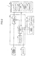
- FIG. 2 is a diagram illustrating a configuration example of the perimeter monitoring system 1 according to the embodiment.
- the perimeter monitoring system 1 includes the image processing device 10, an image capturing device 20, a navigation device 30, a detector 40, and a sensor assembly 50.
- the image capturing device 20 includes a front image capturing unit 20a that is placed in the front of the vehicle C, a rear image capturing unit 20b that is placed in the rear of the vehicle C, a right image capturing unit 20c that is placed in the right side of the vehicle C, and a left image capturing unit 20d that is placed in the left side of the vehicle C.
- FIG. 3 is a diagram illustrating an arrangement example of the image capturing units 20a to 20d.
- the image capturing units 20a to 20d include image capturing elements such as a Charge Coupled Device (CCD) and a Complementary Metal Oxide Semiconductor (CMOS), and outputs images (hereinafter, captured images) around the vehicle C captured by the image capturing elements to the image processing device 10. Moreover, the image capturing units 20a to 20d capture respective images whose imaging directions are front, rear, right, and left directions of the vehicle C.
- image capturing elements such as a Charge Coupled Device (CCD) and a Complementary Metal Oxide Semiconductor (CMOS)
- CCD Charge Coupled Device
- CMOS Complementary Metal Oxide Semiconductor
- the image capturing units 20a to 20d employ wide angle lenses such as fisheye lenses. Each of the image capturing units 20a to 20d has an angle of view of which the size is not less than 180 degrees. By using the image capturing units 20a to 20d, the entire perimeter of the vehicle C can be captured.
- the navigation device 30 illustrated in FIG. 2 includes a display unit 31, a voice output unit 32, an input operating unit 33, and a controller 34.
- the navigation device 30 has a navigation function and an audio function when a driver of the vehicle C is driving.
- the navigation device 30 outputs, to the image processing device 10, information on a screen displayed on the display unit 31 and information on an input operation received by the input operating unit 33.
- the display unit 31 includes a Liquid Crystal Display (LCD).
- the display unit 31 displays, for example, the navigation image 100 (see FIG. 1 ) and an image (hereinafter, television image) based on television broadcasting signals in accordance with an instruction of the controller 34.
- the display unit 31 displays a captured image, a virtual viewpoint image, or a synthesized image, as described later.
- the voice output unit 32 includes a speaker.
- the voice output unit 32 outputs, for example, voice guidance for the navigation function and voices based on television broadcasting signals in accordance with an instruction of the controller 34.
- the input operating unit 33 receives an input operation that is performed by an operator with respect to the navigation device 30.
- the display unit 31 is for example a touch-screen display, the display unit 31 may have a function of the input operating unit 33.
- the controller 34 controls the units included in the navigation device 30.
- the controller 34 causes the display unit 31 to display a predetermined image or causes the voice output unit 32 to output audio data, on the basis of an input operation received by the input operating unit 33, for example.
- the detector 40 includes the right front detector 40a placed in the right front of the vehicle C, the left front detector 40b placed in the left front of the vehicle C, the right rear detector 40c placed in the right rear of the vehicle C, and the left rear detector 40d placed in the left rear of the vehicle C.
- the detectors 40a to 40d are clearance sonars.
- the detectors 40a to 40d detect objects located in the detection ranges R1 to R4 of the respective clearance sonars as obstacles. Each of the detectors 40a to 40d notifies the image processing device 10 of the detected obstacle. It should be noted that the detectors 40a to 40d are not limited to ultrasonic sensors such as for example clearance sonars.
- the detectors 40a to 40d may be radiowave sensors such as for example millimeter wave radars.
- the arrangement of the detector 40 is not limited to the example illustrated in FIG. 3 .
- the detector 40 may be provided in the rear of the vehicle C.
- the number of the detectors 40a to 40d may be four or more.
- the sensor assembly 50 includes various types of sensors, such as a shift sensor 51 and a speed sensor 52, which detect the state of the vehicle C.
- the shift sensor 51 detects the position of a shift lever (not illustrated).
- the position of the shift lever includes “parking” in which the vehicle C is perfectly stopped and “reverse” in which the vehicle C moves backward.
- the speed sensor 52 detects a traveling speed (hereinafter, vehicle speed) of the vehicle C.
- the sensor assembly 50 outputs the detection result of each sensor to the image processing device 10.
- the image processing device 10 includes an image controller 11 (equivalent to example of "display controller"), a determining unit 12, and a storage unit 13.
- the image controller 11 performs various kinds of image processing with respect to image data acquired from the image capturing device 20, and generates a captured image, a virtual viewpoint image, or a synthesized image to be displayed on the display unit 31.
- the image controller 11 acquires captured image data from the image capturing units 20a to 20d.
- the image controller 11 selects one or more images from among the captured images of the image capturing units 20a to 20d, depending on the type of an image to be displayed on the display unit 31.
- the image controller 11 selects one or more captured images in accordance with the notification of the determining unit 12.
- the image controller 11 performs a coordinate transformation process with respect to the plurality of captured image, and generates a virtual viewpoint image that is an image viewed from a virtual viewpoint.
- the image controller 11 projects (maps), for example, the captured images on a predetermined projection plane, and sets, as the virtual viewpoint image, an image in a predetermined viewing angle area when being viewed from the virtual viewpoint, among the captured images projected on the predetermined projection plane.
- the image controller 11 stores a table that indicates a correspondence relationship between the position of data included in the captured images of the image capturing units 20a to 20d and the position of the predetermined projection plane. By using the table, the image controller 11 projects the data included in the captured images of the image capturing units 20a to 20d on the corresponding position of the predetermined projection plane.
- the predetermined projection plane has, for example, a substantially hemispherical shape (for example, bowl shape).
- the central area (for example, bottom of bowl) of the hemispherical shape is the position of the vehicle C, and the outside (outer circumferential area of substantially hemispherical shape, for example) of the position of the vehicle C is equivalent to an area around the vehicle C.
- the predetermined projection plane is not limited to a curved surface. It may be a flat surface, for example.
- the image controller 11 generates a synthesized image obtained by superimposing a predetermined notification image on a virtual viewpoint image.
- the predetermined notification image is an image corresponding to any of the detection ranges R1 to R4 of the detector 40.
- the image controller 11 generates a synthesized image by superimposing a notification image on the virtual viewpoint image, in which the notification image is an image that indicates a detection range (R1 to R4) in a direction (front or rear direction) in which the detector 40 detects an obstacle.
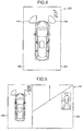
- FIG. 4 is a diagram illustrating an example of a notification screen 200 that is generated from the image controller 11.
- the image controller 11 when the detector 40 detects the person H located in front of the vehicle C as an obstacle, the image controller 11 generates, as the notification screen 200, the synthesized image 300 obtained by superimposing images 41a, 41b (notification images) corresponding to the detection ranges R1, R2 of the detectors 40a, 40b provided in the front of the vehicle C on a virtual viewpoint image 600.
- the images 41a, 41b on the virtual viewpoint image 600 are not necessarily identical with the actual detection ranges R1, R2. It is sufficient that the synthesized image 300 is an image that indicates where the obstacle exists around the vehicle C. For example, because the notification image may be an arrow, it may not be the images 41a, 41b corresponding to the detection ranges R1, R2.
- the notification screen 200 generated from the image controller 11 is not limited to the example illustrated in FIG. 4 .
- the detected obstacle may be displayed after highlighting is performed by surrounding the obstacle with a frame.
- the image controller 11 may generate the notification screen 200 by apposing the synthesized image 300 obtained by superimposing the notification images 41a, 41b on the virtual viewpoint image and the front captured image 500 in which highlighting is performed on the obstacle.
- the positions at which the notification images 41a, 41b are superimposed on the virtual viewpoint image 600 are not limited to the example illustrated in FIGS. 4 and 5 .
- the image controller 11 may superimpose a notification image on a vehicle image included in the synthesized image 300.
- the image controller 11 generates the synthesized image 300 and the captured image 500 or the virtual viewpoint image 600 in accordance with the notification of the determining unit 12, and causes the display unit 31 to display the image(s).
- the determining unit 12 determines whether a switching condition to the notification screen 200 for notifying the driver of the presence of an obstacle is satisfied when the obstacle is detected by the detector 40. When it is determined that the switching condition is satisfied, the determining unit 12 notifies the image controller 11 of the effect that the detection result by the detector 40 and the notification screen 200 are displayed.
- the determining unit 12 determines whether a termination condition for terminating the display of the notification screen 200 is satisfied. When it is determined that the termination condition is satisfied, the determining unit 12 notifies the image controller 11 to terminate the display of the notification screen 200.
- the determining unit 12 determines whether each of display conditions is satisfied, for example. When all the display conditions are satisfied, the determining unit 12 determines that the switching condition is satisfied.
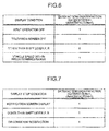
- the display conditions will be explained by using FIG. 6.
- FIG. 6 is a diagram illustrating a display condition table that indicates the satisfaction or unsatisfaction of each display condition.
- a display condition determined by the determining unit 12 includes, as an example, the presence or absence of an input operation with respect to the navigation device 30. For example, when an input operation with respect to the navigation device 30 is not performed until a predetermined time passes after the detector 40 detects an obstacle, the determining unit 12 determines that there is not the input operation.
- the determining unit 12 determines that the condition of "input operation OFF" is satisfied, and sets “input operation OFF" of the display condition table to "1".
- the determining unit 12 determines that there is the input operation, and sets "input operation OFF" of the display condition table to "0".
- the presence or absence of an input operation with respect to the navigation device 30 is determined in a predetermined time after detecting an obstacle.
- the presence or absence of the input operation may, however, be determined in a predetermined time before detecting an obstacle.
- the determining unit 12 determines that there is not the input operation.
- the determining unit 12 determines whether the display unit 31 is displaying a television screen that includes television images. When the television screen is not displayed on the display unit 31, for example, the determining unit 12 determines that the display condition is satisfied, and sets "television screen OFF" of the display condition table to "1". On the other hand, when the television screen is displayed on the display unit 31, for example, the determining unit 12 determines that the display condition is not satisfied, and sets "television screen OFF" of the display condition table to "0".
- the determining unit 12 determines that the driver may not be notified of the obstacle and thus the switching to the notification screen 200 is not performed. As a result, the driver can watch television without being obstructed by the notification screen 200. Moreover, when the television screen is not displayed on the display unit, the determining unit 12 can appropriately notify the driver of an obstacle by determining that the switching to the notification screen 200 is performed.
- the determining unit 12 determines whether the display condition is satisfied in accordance with the position of the shift lever, for example. Specifically, when the shift lever is located at a position other than parking and reverse, for example, the determining unit 12 determines that the display condition is satisfied, and sets "other than shift lever P, R" of the display condition table to "1". On the other hand, when the shift lever is located at the position of parking or reverse, for example, the determining unit 12 determines that the display condition is not satisfied, and sets "other than shift lever P, R" of the display condition table to "0".
- the vehicle C When the shift lever is located at the position of "P", namely, the position of parking, the vehicle C is stopping. In this case, because the vehicle C does not collide against an obstacle, the determining unit 12 determines that the switching to the notification screen 200 is not performed. Therefore, when the vehicle C may collide against the detected obstacle, the determining unit 12 can appropriately notify the driver of the obstacle by determining that the switching to the notification screen 200 is performed.
- the determining unit 12 determines that the switching to the notification screen 200 is not performed. As described above, when the driver does not sufficiently pay attention to the perimeter of the vehicle C, or when the driver is not notified of the obstacle, the determining unit 12 can appropriately notify the driver of the obstacle by determining that the switching to the notification screen 200 is performed.
- the determining unit 12 determines whether the display condition is satisfied in accordance with the vehicle speed of the vehicle C, for example. Specifically, when the speed of the vehicle C is not less than a first speed Vth1 that is faster than 0 km/h and is not more than a second speed Vth2 that is faster than the first speed Vth1, for example, the determining unit 12 determines that the display condition is satisfied, and sets "vehicle speed within predetermined range" of the display condition table to "1". On the other hand, when the vehicle speed is smaller than the first speed Vth1 or is larger than the second speed Vth2, the determining unit 12 determines that the display condition is not satisfied, and sets "vehicle speed within predetermined range" of the display condition table to "0"
- the vehicle speed is smaller than the first speed Vth1, the vehicle C is substantially stopping, and thus a collision possibility against an obstacle is small.
- the driver concentrates on the drive of the vehicle.
- the determining unit 12 determines that the switching to the notification screen 200 is not performed when the vehicle speed is out of the predetermined range.
- the determining unit 12 can appropriately notify the driver of an obstacle by determining that the switching to the notification screen 200 is performed when the vehicle speed is within the predetermined range.
- the determining unit 12 determines that the switching condition is satisfied.
- the condition of "other than shift lever P, R" is "0" in the example illustrated in FIG. 6 , it is not determined that all the display conditions are satisfied.
- the determining unit 12 determines that the switching condition is not satisfied.
- display conditions are not limited to four.
- the determining unit 12 may determine that the switching to the notification screen 200 is not performed because it is concerned that the guidance of the navigation device 30 is obstructed.
- the number of display conditions may be four or more or four or less.
- the driver may select a condition in which the switching to the notification screen 200 is performed.
- the determining unit 12 determines whether each of display stop conditions is satisfied, for example. When all the display stop conditions are satisfied, the determining unit 12 determines that a termination condition is satisfied, and instructs the image controller 11 to terminate the display of the notification screen 200.
- FIG. 7 is a diagram illustrating a display stop condition table that indicates the satisfaction or unsatisfaction of each display stop condition.
- FIG. 8 is a diagram illustrating a stop OR condition table that indicates the satisfaction or unsatisfaction of a stop OR condition of the display stop conditions.
- FIG. 9 is a diagram explaining the stop OR condition.
- the determining unit 12 determines whether the display unit 31 is displaying the notification screen 200 that indicates the detection result of the detector 40. When the display unit 31 is displaying the notification screen 200, the determining unit 12 determines that the display stop condition of "notification screen display” is satisfied, and sets “notification screen display” of the display stop condition table illustrated in FIG. 7 to "1 ". On the other hand, when the display unit 31 is not displaying the notification screen 200, the determining unit 12 determines that the display stop condition of "notification screen display” is not satisfied, and sets “notification screen display” of the display stop condition table to "0".
- the determining unit 12 determines whether the display stop condition is satisfied in accordance with the position of the shift lever. Specifically, when the position of the shift lever is a position other than parking and reverse, for example, the determining unit 12 determines that the display stop condition is satisfied, and sets "other than shift lever P, R" of the display stop condition table to "1". On the other hand, when the shift lever is located at the position of parking or reverse, for example, the determining unit 12 determines that the display stop condition is not satisfied, and sets "other than shift lever P, R" of the display condition table to "0".
- the determining unit 12 determines whether an OR condition as the display stop condition is satisfied. When at least one of stop OR conditions is satisfied, the determining unit 12 determines that the OR condition is satisfied.
- the determining unit 12 determines whether a switch of the detector 40 is OFF. When the switch of the detector 40 is OFF, the determining unit 12 determines that the switch of the detector 40 is OFF, and sets "detector switch OFF" of the stop OR condition table illustrated in FIG. 8 to "1 ". On the other hand, when the switch of the detector 40 is ON, the determining unit 12 determines that the switch of the detector 40 is not OFF, and sets "detector switch OFF" of the stop OR condition table to "0".
- the switch of the detector 40 can be switched by the driver between ON and OFF, for example. Therefore, when the switch of the detector 40 is switched by the driver to OFF, for example, the determining unit 12 determines that the detection of an obstacle is unnecessary and thus the display of the notification screen 200 is terminated.
- the determining unit 12 determines whether a time in which an obstacle is not detected by the detector 40 exceeds a predetermined time P1. When the obstacle is not detected by the detector 40 for a predetermined time, the determining unit 12 determines that the predetermined time has passed after the obstacle is detected, and sets "No obstacle detection for predetermined time" of the stop OR condition table to "1". On the other hand, when the obstacle is detected within the predetermined time, the determining unit 12 determines that the predetermined time has not passed after the obstacle is detected, and sets "No obstacle detection for predetermined time" of the stop OR condition table to "0".
- the determining unit 12 determines to terminate the display of the notification screen 200 because the obstacle does not exist around the vehicle C.
- the determining unit 12 determines whether a time in which the speed of the vehicle C is less than the first speed Vth1 exceeds a predetermined time. When the time in which the vehicle speed is smaller than the first speed Vth1 exceeds the predetermined time, the determining unit 12 sets "vehicle speed below first speed Vth1 for predetermined time" of the stop OR condition table to "1". On the other hand, when the time in which the vehicle speed is smaller than the first speed Vth1 is not more than the predetermined time, the determining unit 12 sets "vehicle speed below first speed Vth1 for predetermined time" of the stop OR condition table to "0".
- the determining unit 12 determines whether the speed of the vehicle C exceeds a third speed Vth3 faster than the second speed Vth2. When the vehicle speed exceeds the third speed Vth3, the determining unit 12 sets "vehicle speed larger than third speed Vth3" of the stop OR condition table to "1". On the other hand, when the vehicle speed is smaller than the third speed Vth3, the determining unit 12 "vehicle speed larger than third speed Vth3" of the stop OR condition table to "0".
- FIG. 9 it will be explained about the relationship between the vehicle speed and the determination by the determining unit 12 for the display condition and the display stop condition.
- the case, in which the determining unit 12 displays the notification screen 200, namely, it is determined that the display condition is satisfied, is explained as "ON"
- the case, in which the determining unit 12 does not display the notification screen 200, namely, it is determined that the display stop condition is satisfied is explained as "OFF”.
- the upper part illustrates a time change in the speed of the vehicle C
- the lower part illustrates the determination result of the determining unit 12.
- the determining unit 12 determines the state of the notification as "ON”, namely, determines to display the notification screen 200.
- the determining unit 12 determines the state of the notification as "OFF”, namely, determines not to display the notification screen 200.
- the determining unit 12 determines the state of the notification as "ON”, namely, determines to display the notification screen 200.
- the determining unit 12 determines the state of the notification as "OFF”, namely, determines not to display the notification screen 200.
- a speed (second speed Vth2) at which it is determined that the notification screen 200 is displayed is different from a speed (third speed Vth3) at which it is determined that the display of the notification screen 200 is terminated. Therefore, when the vehicle speed is frequently changed like a time T1 illustrated in FIG. 9 , for example, the notification screen 200 cannot be prevented from being frequently switched between start and termination.
- the display of the notification screen 200 is terminated.
- the notification screen 200 cannot be prevented from being frequently switched between start and termination.
- the determining unit 12 determines that the OR condition is satisfied, and sets "OR condition satisfaction" of the display stop condition table as illustrated in FIG. 7 to "1 ".
- the determining unit 12 determines that the termination condition is satisfied. In the example illustrated in FIG. 7 , because all the display stop conditions are "1", the determining unit 12 determines that the termination condition is satisfied, and instructs the image controller 11 to terminate the notification screen 200.
- the display stop condition and the stop OR condition are not limited to the above case.
- the determining unit 12 may assume that the driver has confirmed the notification screen 200 and determine to terminate the display of the notification screen 200.
- the number of the display stop conditions and the stop OR conditions may be'four or three or more, or may be four or three or less.
- the driver may select a condition for terminating the notification screen 200.
- the determining unit 12 determines to terminate the display of the notification screen 200 when all the display stop conditions illustrated in FIG. 7 are satisfied.
- the present embodiment is not limited to the above.
- the determining unit 12 may determine to terminate the display of the notification screen 200 regardless of the satisfaction or unsatisfaction of the OR condition.
- the determining unit 12 may determine to terminate the display of the notification screen 200.
- the storage unit 13 stores, for example, the display condition table, the display stop condition table, and the stop OR condition table. Moreover, the storage unit 13 stores information required for the determination of whether the switching condition is satisfied and the determination of whether the termination condition is satisfied, which are performed by the determining unit 12.
- the storage unit 13 is a semiconductor memory device such as a Random Access Memory (RAM) and a flash memory, or a storage device such as a hard disk and an optical disc.
- the image processing device 10 executes the notification processing that includes notification start processing and notification termination processing.
- FIG. 10 is a flowchart illustrating notification start processing that is performed by the image processing device 10.
- the image processing device 10 determines whether the detector 40 detects an obstacle (Step S101). When it is determined that the detector 40 does not detect an obstacle (Step S101: No), the image processing device 10 returns the process to Step S101 to wait for the detection of an obstacle.
- Step S101: Yes the image processing device 10 determines whether a virtual viewpoint screen including the synthesized image 300 is displayed on the display unit 31 (Step S102).
- Step S102: Yes the image processing device 10 advances the process to Step S104.
- Step S102 When the virtual viewpoint screen including the synthesized image 300 is not displayed on the display unit 31 (Step S102: No), the image processing device 10 determines whether a switching condition is satisfied (Step S103). When the switching condition is not satisfied (Step S103: No), the image processing device 10 determines that the switching to the notification screen 200 is unnecessary, and terminates the notification start processing.
- Step S103 When the switching condition is satisfied (Step S103: Yes), the image processing device 10 generates the synthesized image 300 (Step S104), and causes the display unit 31 to display the notification screen 200 obtained by superimposing a notification image on the generated synthesized image 300 (Step S105).
- the image processing device 10 At timing at which the display condition is changed, for example, the vehicle speed of the vehicle C is changed or the position of the shift lever is changed, the image processing device 10 previously updates the display condition table, and performs the determination on the satisfaction or unsatisfaction of the switching condition by referring to the display condition table in Step S103. Alternatively, the image processing device 10 may determine whether the switching condition is satisfied by determining all the display conditions at timing at which Step S103 is executed.
- the image processing device 10 may exchange Step S102 for Step S103, or may simultaneously execute Steps S102 and S103.
- FIG. 11 is a flowchart illustrating notification termination processing that is performed by the image processing device 10.
- the image processing device 10 executes the notification termination processing after executing the notification start processing.
- Step S201 the image processing device 10 continues to display the notification screen 200 on the display unit 31.
- Step S202 determines whether a termination condition is satisfied.
- Step S202 the image processing device 10 returns the process to Step S201, and continues to display the notification screen 200 on the display unit 31.
- Step S202 when it is determined that the termination condition is satisfied (Step S202: Yes), the image processing device 10 instructs the display unit 31 to terminate the display of the notification screen 200 (Step S203).
- the display unit 31 displays for example the screen just before displaying the notification screen 200.
- the image processing device 10 may determine an image to be displayed on the display unit 31.
- the image processing device 10 At timing at which the display stop condition and the stop OR condition are changed, for example, the vehicle speed of the vehicle C is changed or the position of the shift lever is changed, the image processing device 10 previously updates the display stop condition table and the stop OR condition table, and performs the determination on the satisfaction or unsatisfaction of the termination condition by referring to the display stop condition table in Step S202.
- the image processing device 10 may execute Step S202 at timing at which the display stop condition table and the stop OR condition table are updated.
- the image processing device 10 may determine whether the termination condition is satisfied by determining all the display stop conditions at timing at which Step S202 is executed.
- the image processing device 10 changes the display of the display unit 31 to the notification screen 200 when the switching condition to the notification screen 200 is satisfied. As a result, the image processing device 10 can appropriately notify a driver of an obstacle in the case of requiring a notification.
- the image processing device 10 determines whether a driver is notified of an obstacle after the detector 40 detects the obstacle, the present embodiment is not limited to the above. For example, when the display unit 31 does not display a virtual viewpoint screen including the synthesized image 300 and a switching condition is satisfied, the image processing device 10 determines that the present mode is a notification mode for notifying a driver of an obstacle. The image processing device 10 notifies a driver of an obstacle when receiving the detection notification of the obstacle from the detector 40 in a detection mode.
- the image processing device 10 since the image processing device 10 previously switches between notification and detection modes, the image processing device 10 does not need to determine the satisfaction or unsatisfaction of the switching condition at timing at which an obstacle is detected, and thus can immediately notify the driver of the obstacle at timing at which the detector 40 detects the obstacle.
- the image processing device 10 terminates the detection mode when the notification screen 200 is displayed on the display unit 31, namely, it is determined that the display stop conditions excluding the condition of "notification screen display" of FIG. 7 are satisfied.
- the detection mode is terminated when the display stop conditions different from the display condition are satisfied, it is possible to restrain the frequent switching between the start and termination of the detection mode in a short period of time.
- an image processing device and an image processing method which can appropriately notify a driver of a vehicle of an obstacle.
Landscapes
- Engineering & Computer Science (AREA)
- Remote Sensing (AREA)
- Radar, Positioning & Navigation (AREA)
- Physics & Mathematics (AREA)
- General Physics & Mathematics (AREA)
- Computer Networks & Wireless Communication (AREA)
- Transportation (AREA)
- Mechanical Engineering (AREA)
- Combustion & Propulsion (AREA)
- Chemical & Material Sciences (AREA)
- Theoretical Computer Science (AREA)
- Multimedia (AREA)
- Electromagnetism (AREA)
- Acoustics & Sound (AREA)
- Automation & Control Theory (AREA)
- Computer Vision & Pattern Recognition (AREA)
- Mathematical Physics (AREA)
- Human Computer Interaction (AREA)
- General Health & Medical Sciences (AREA)
- Psychiatry (AREA)
- Social Psychology (AREA)
- Health & Medical Sciences (AREA)
- Traffic Control Systems (AREA)
- Closed-Circuit Television Systems (AREA)
- Fittings On The Vehicle Exterior For Carrying Loads, And Devices For Holding Or Mounting Articles (AREA)
- Navigation (AREA)
- Auxiliary Drives, Propulsion Controls, And Safety Devices (AREA)
- Studio Devices (AREA)
- Controls And Circuits For Display Device (AREA)
Applications Claiming Priority (1)
| Application Number | Priority Date | Filing Date | Title |
|---|---|---|---|
| JP2015103861A JP6224029B2 (ja) | 2015-05-21 | 2015-05-21 | 画像処理装置および画像処理方法 |
Publications (2)
| Publication Number | Publication Date |
|---|---|
| EP3096306A2 true EP3096306A2 (de) | 2016-11-23 |
| EP3096306A3 EP3096306A3 (de) | 2016-12-21 |
Family
ID=56087116
Family Applications (1)
| Application Number | Title | Priority Date | Filing Date |
|---|---|---|---|
| EP16169996.2A Ceased EP3096306A3 (de) | 2015-05-21 | 2016-05-17 | Bildverarbeitungsvorrichtung und bildverarbeitungsverfahren |
Country Status (4)
| Country | Link |
|---|---|
| US (1) | US10579884B2 (de) |
| EP (1) | EP3096306A3 (de) |
| JP (1) | JP6224029B2 (de) |
| CN (1) | CN106169061B (de) |
Families Citing this family (8)
| Publication number | Priority date | Publication date | Assignee | Title |
|---|---|---|---|---|
| JP6477562B2 (ja) * | 2016-03-18 | 2019-03-06 | 株式会社デンソー | 情報処理装置 |
| EP3299241B1 (de) * | 2016-09-26 | 2021-11-10 | Volvo Car Corporation | Verfahren, system und fahrzeug für den einsatz einer objektanzeigevorrichtung in einem fahrzeug |
| JP6501805B2 (ja) * | 2017-01-04 | 2019-04-17 | 株式会社デンソーテン | 画像処理装置および画像処理方法 |
| JP2018110328A (ja) * | 2017-01-04 | 2018-07-12 | 株式会社デンソーテン | 画像処理装置および画像処理方法 |
| US11100729B2 (en) * | 2017-08-08 | 2021-08-24 | Panasonic Intellectual Property Corporation Of America | Information processing method, information processing system, and program |
| CN109955848B (zh) * | 2017-12-25 | 2021-06-11 | 郑州宇通客车股份有限公司 | 一种车辆停靠自动运行控制方法和控制系统 |
| JP7247851B2 (ja) * | 2019-10-11 | 2023-03-29 | トヨタ自動車株式会社 | 運転者支援装置 |
| JP7829530B2 (ja) * | 2023-09-29 | 2026-03-13 | 本田技研工業株式会社 | 運転支援装置、方法およびプログラム |
Citations (2)
| Publication number | Priority date | Publication date | Assignee | Title |
|---|---|---|---|---|
| JP2013190957A (ja) | 2012-03-13 | 2013-09-26 | Toyota Motor Corp | 周辺監視装置及び周辺監視方法 |
| US20140347485A1 (en) * | 2013-05-23 | 2014-11-27 | GM Global Technology Operations LLC | Enhanced front curb viewing system |
Family Cites Families (56)
| Publication number | Priority date | Publication date | Assignee | Title |
|---|---|---|---|---|
| US6885968B2 (en) * | 2000-05-08 | 2005-04-26 | Automotive Technologies International, Inc. | Vehicular exterior identification and monitoring system-agricultural product distribution |
| JPH09159468A (ja) * | 1995-12-08 | 1997-06-20 | Matsushita Electric Ind Co Ltd | 走行位置表示装置 |
| JP3992870B2 (ja) * | 1999-04-16 | 2007-10-17 | パイオニア株式会社 | 情報再生装置 |
| US7366595B1 (en) * | 1999-06-25 | 2008-04-29 | Seiko Epson Corporation | Vehicle drive assist system |
| JP2001216520A (ja) * | 2000-01-31 | 2001-08-10 | Yazaki Corp | 車両用周辺監視装置 |
| JP4354085B2 (ja) * | 2000-05-09 | 2009-10-28 | 本田技研工業株式会社 | 車両用ヘッドアップディスプレイ装置 |
| US7145519B2 (en) * | 2002-04-18 | 2006-12-05 | Nissan Motor Co., Ltd. | Image display apparatus, method, and program for automotive vehicle |
| EP1521059A1 (de) * | 2003-09-30 | 2005-04-06 | Mazda Motor Corporation | Routenführungsgerät, -Verfahren und -Komputerprogramm |
| US7561966B2 (en) * | 2003-12-17 | 2009-07-14 | Denso Corporation | Vehicle information display system |
| JP4657765B2 (ja) * | 2005-03-09 | 2011-03-23 | 三菱自動車工業株式会社 | ノーズビューシステム |
| WO2007015446A1 (ja) * | 2005-08-02 | 2007-02-08 | Nissan Motor Co., Ltd. | 車両周囲監視装置及び車両周囲監視方法 |
| JP4353162B2 (ja) * | 2005-09-26 | 2009-10-28 | トヨタ自動車株式会社 | 車輌周囲情報表示装置 |
| JP4883977B2 (ja) * | 2005-10-05 | 2012-02-22 | アルパイン株式会社 | 車両用画像表示装置 |
| JP4934308B2 (ja) * | 2005-10-17 | 2012-05-16 | 三洋電機株式会社 | 運転支援システム |
| JP4887980B2 (ja) * | 2005-11-09 | 2012-02-29 | 日産自動車株式会社 | 車両用運転操作補助装置および車両用運転操作補助装置を備えた車両 |
| JP4846426B2 (ja) * | 2006-04-20 | 2011-12-28 | パナソニック株式会社 | 車両周囲監視装置 |
| US7617042B2 (en) * | 2006-06-30 | 2009-11-10 | Microsoft Corporation | Computing and harnessing inferences about the timing, duration, and nature of motion and cessation of motion with applications to mobile computing and communications |
| JP4743054B2 (ja) * | 2006-09-06 | 2011-08-10 | 株式会社デンソー | 車両のドライブレコーダ |
| JP4969269B2 (ja) * | 2007-02-21 | 2012-07-04 | アルパイン株式会社 | 画像処理装置 |
| JP5088669B2 (ja) * | 2007-03-23 | 2012-12-05 | 株式会社デンソー | 車両周辺監視装置 |
| JP4325705B2 (ja) * | 2007-06-15 | 2009-09-02 | 株式会社デンソー | 表示システム及びプログラム |
| US8332097B2 (en) * | 2007-12-14 | 2012-12-11 | Denso International America, Inc. | Method of detecting an object near a vehicle |
| JP5345350B2 (ja) * | 2008-07-30 | 2013-11-20 | 富士重工業株式会社 | 車両の運転支援装置 |
| US8229618B2 (en) * | 2008-09-11 | 2012-07-24 | Deere & Company | Leader-follower fully autonomous vehicle with operator on side |
| KR100966288B1 (ko) * | 2009-01-06 | 2010-06-28 | 주식회사 이미지넥스트 | 주변 영상 생성 방법 및 장치 |
| JP2010183170A (ja) * | 2009-02-03 | 2010-08-19 | Denso Corp | 車両用表示装置 |
| JP2010215027A (ja) * | 2009-03-13 | 2010-09-30 | Fujitsu Ten Ltd | 車両用運転支援装置 |
| US8344894B2 (en) * | 2009-04-02 | 2013-01-01 | GM Global Technology Operations LLC | Driver drowsy alert on full-windshield head-up display |
| JP5376223B2 (ja) * | 2009-05-18 | 2013-12-25 | アイシン精機株式会社 | 運転支援装置 |
| JP5271154B2 (ja) * | 2009-05-29 | 2013-08-21 | 富士通テン株式会社 | 画像生成装置及び画像表示システム |
| JP5627253B2 (ja) * | 2009-05-29 | 2014-11-19 | 富士通テン株式会社 | 画像処理装置、電子装置、および、画像処理方法 |
| JP2011111061A (ja) * | 2009-11-27 | 2011-06-09 | Fujitsu Ten Ltd | 車載表示システム |
| JP2011118483A (ja) * | 2009-11-30 | 2011-06-16 | Fujitsu Ten Ltd | 車載装置および認知支援システム |
| JP5302227B2 (ja) * | 2010-01-19 | 2013-10-02 | 富士通テン株式会社 | 画像処理装置、画像処理システム、および、画像処理方法 |
| EP2544161B1 (de) * | 2010-03-03 | 2014-12-24 | Honda Motor Co., Ltd. | Vorrichtung zur überwachung des umgebungsbereichs eines fahrzeugs |
| US9131123B2 (en) * | 2010-03-19 | 2015-09-08 | Panasonic Intellectual Property Management Co., Ltd. | Device for monitoring surroundings of vehicle and method for monitoring surroundings of vehicle |
| JP5604146B2 (ja) * | 2010-03-25 | 2014-10-08 | 富士通テン株式会社 | 車載照明装置、画像処理装置、画像表示システム及び照明方法 |
| JP5113881B2 (ja) * | 2010-06-03 | 2013-01-09 | 株式会社デンソー | 車両周辺監視装置 |
| JP5281664B2 (ja) * | 2011-02-23 | 2013-09-04 | クラリオン株式会社 | 車線逸脱警報装置および車線逸脱警報システム |
| JP5765995B2 (ja) * | 2011-03-31 | 2015-08-19 | 富士通テン株式会社 | 画像表示システム |
| JP5741173B2 (ja) * | 2011-04-19 | 2015-07-01 | トヨタ自動車株式会社 | 画像表示装置、及び、画像表示方法 |
| AU2012268476B2 (en) * | 2011-06-07 | 2014-05-15 | Komatsu Ltd. | Perimeter monitoring device for work vehicle |
| CN107097721B (zh) * | 2011-08-26 | 2020-03-06 | 松下知识产权经营株式会社 | 驾驶辅助装置 |
| US8942692B2 (en) * | 2011-12-02 | 2015-01-27 | Text Safe Teens, Llc | Remote mobile device management |
| DE102011121442A1 (de) * | 2011-12-16 | 2013-06-20 | Gm Global Technology Operations, Llc | Autonomes Anfahren |
| CN104302517A (zh) * | 2012-05-18 | 2015-01-21 | 丰田自动车株式会社 | 车辆的信息显示装置 |
| BR112015002997A2 (pt) * | 2012-08-17 | 2017-07-04 | Honda Motor Co Ltd | dispositivo de assistência á condução |
| JP5411976B1 (ja) * | 2012-09-21 | 2014-02-12 | 株式会社小松製作所 | 作業車両用周辺監視システム及び作業車両 |
| US9446713B2 (en) * | 2012-09-26 | 2016-09-20 | Magna Electronics Inc. | Trailer angle detection system |
| JP6232804B2 (ja) * | 2013-07-25 | 2017-11-22 | 株式会社デンソー | 車両用ユーザインタフェースシステム |
| JP2015049842A (ja) * | 2013-09-04 | 2015-03-16 | トヨタ自動車株式会社 | 注意喚起表示装置及び注意喚起表示方法 |
| JP5776995B2 (ja) | 2014-03-11 | 2015-09-09 | クラリオン株式会社 | 車両用周辺監視装置 |
| CA2863656C (en) * | 2014-04-25 | 2017-04-25 | Takeshi Kurihara | Surroundings monitoring system, work vehicle, and surroundings monitoring method |
| CN104401261B (zh) * | 2014-11-24 | 2016-09-07 | 上汽大众汽车有限公司 | 汽车前方盲区探测系统及其探测方法 |
| JP6417994B2 (ja) * | 2015-02-09 | 2018-11-07 | 株式会社デンソー | 車両用表示制御装置及び車両用表示制御方法 |
| JP6426025B2 (ja) * | 2015-02-20 | 2018-11-21 | クラリオン株式会社 | 情報処理装置 |
-
2015
- 2015-05-21 JP JP2015103861A patent/JP6224029B2/ja active Active
-
2016
- 2016-05-11 CN CN201610308370.0A patent/CN106169061B/zh active Active
- 2016-05-16 US US15/155,496 patent/US10579884B2/en active Active
- 2016-05-17 EP EP16169996.2A patent/EP3096306A3/de not_active Ceased
Patent Citations (2)
| Publication number | Priority date | Publication date | Assignee | Title |
|---|---|---|---|---|
| JP2013190957A (ja) | 2012-03-13 | 2013-09-26 | Toyota Motor Corp | 周辺監視装置及び周辺監視方法 |
| US20140347485A1 (en) * | 2013-05-23 | 2014-11-27 | GM Global Technology Operations LLC | Enhanced front curb viewing system |
Also Published As
| Publication number | Publication date |
|---|---|
| JP2016218795A (ja) | 2016-12-22 |
| JP6224029B2 (ja) | 2017-11-01 |
| CN106169061B (zh) | 2021-02-19 |
| US20160342849A1 (en) | 2016-11-24 |
| CN106169061A (zh) | 2016-11-30 |
| US10579884B2 (en) | 2020-03-03 |
| EP3096306A3 (de) | 2016-12-21 |
Similar Documents
| Publication | Publication Date | Title |
|---|---|---|
| EP3096306A2 (de) | Bildverarbeitungsvorrichtung und bildverarbeitungsverfahren | |
| JP4900232B2 (ja) | 車両用駐車支援装置および映像表示方法 | |
| JP6785953B2 (ja) | 車載用監視カメラ装置 | |
| US9691283B2 (en) | Obstacle alert device | |
| JP6014433B2 (ja) | 画像処理装置、画像処理方法、及び、画像処理システム | |
| JP2008301091A (ja) | 車両用周辺監視装置 | |
| US20160088260A1 (en) | Image processing apparatus | |
| WO2013031161A1 (ja) | 運転支援装置 | |
| KR101487161B1 (ko) | 드래그 앤드 드롭을 통한 차량의 주차지원 방법 | |
| JPWO2013046408A1 (ja) | 画像表示装置及び画像表示方法 | |
| JP2013161440A (ja) | 車両周辺監視装置 | |
| JP2008174076A (ja) | 車両周辺監視装置、その表示方法 | |
| JP2010184604A (ja) | 車両周辺表示装置 | |
| JP2013046482A (ja) | 給電装置への誘導装置、及びそれを用いた車両充電位置自動駐車制御システム | |
| JP6447427B2 (ja) | 後方用電子ミラー、及び制御システム | |
| US11394926B2 (en) | Periphery monitoring apparatus | |
| US20200361376A1 (en) | Rear display device | |
| WO2016092967A1 (ja) | 画像生成装置及び画像生成方法 | |
| JP2008013022A (ja) | 車両の運転支援装置 | |
| JP4693561B2 (ja) | 車両周辺監視装置 | |
| JP6555240B2 (ja) | 車両用撮影表示装置及び車両用撮影表示プログラム | |
| JP2012090087A (ja) | 車両周辺の画像を用いた運転支援装置 | |
| JP2012188058A (ja) | 表示装置 | |
| JP2013191052A (ja) | 車両周辺監視装置 | |
| JP6523801B2 (ja) | 画像処理装置および画像処理方法 |
Legal Events
| Date | Code | Title | Description |
|---|---|---|---|
| PUAI | Public reference made under article 153(3) epc to a published international application that has entered the european phase |
Free format text: ORIGINAL CODE: 0009012 |
|
| PUAL | Search report despatched |
Free format text: ORIGINAL CODE: 0009013 |
|
| AK | Designated contracting states |
Kind code of ref document: A2 Designated state(s): AL AT BE BG CH CY CZ DE DK EE ES FI FR GB GR HR HU IE IS IT LI LT LU LV MC MK MT NL NO PL PT RO RS SE SI SK SM TR |
|
| AX | Request for extension of the european patent |
Extension state: BA ME |
|
| AK | Designated contracting states |
Kind code of ref document: A3 Designated state(s): AL AT BE BG CH CY CZ DE DK EE ES FI FR GB GR HR HU IE IS IT LI LT LU LV MC MK MT NL NO PL PT RO RS SE SI SK SM TR |
|
| AX | Request for extension of the european patent |
Extension state: BA ME |
|
| RIC1 | Information provided on ipc code assigned before grant |
Ipc: B60Q 1/52 20060101ALI20161117BHEP Ipc: G06K 9/00 20060101ALI20161117BHEP Ipc: G08G 1/16 20060101AFI20161117BHEP Ipc: G01S 13/93 20060101ALI20161117BHEP Ipc: B60W 40/105 20120101ALI20161117BHEP |
|
| 17P | Request for examination filed |
Effective date: 20170621 |
|
| RBV | Designated contracting states (corrected) |
Designated state(s): AL AT BE BG CH CY CZ DE DK EE ES FI FR GB GR HR HU IE IS IT LI LT LU LV MC MK MT NL NO PL PT RO RS SE SI SK SM TR |
|
| RIC1 | Information provided on ipc code assigned before grant |
Ipc: G01S 7/10 20060101ALI20180830BHEP Ipc: B60W 40/105 20120101ALI20180830BHEP Ipc: G06K 9/00 20060101ALI20180830BHEP Ipc: G01S 7/20 20060101ALI20180830BHEP Ipc: G01S 15/89 20060101ALI20180830BHEP Ipc: G01S 13/87 20060101ALI20180830BHEP Ipc: G01S 13/86 20060101ALI20180830BHEP Ipc: G01S 15/02 20060101ALI20180830BHEP Ipc: G01S 13/93 20060101ALI20180830BHEP Ipc: G01C 21/26 20060101AFI20180830BHEP Ipc: G06T 7/20 20060101ALI20180830BHEP Ipc: G01S 7/62 20060101ALI20180830BHEP Ipc: B60Q 1/52 20060101ALI20180830BHEP Ipc: G06T 11/60 20060101ALI20180830BHEP Ipc: G01S 15/93 20060101ALI20180830BHEP Ipc: G08G 1/16 20060101ALI20180830BHEP Ipc: G01S 13/89 20060101ALI20180830BHEP |
|
| 17Q | First examination report despatched |
Effective date: 20181004 |
|
| STAA | Information on the status of an ep patent application or granted ep patent |
Free format text: STATUS: THE APPLICATION HAS BEEN REFUSED |
|
| 18R | Application refused |
Effective date: 20200211 |