EP3093603B1 - Récipient contenant un matériau de stockage thermique - Google Patents
Récipient contenant un matériau de stockage thermique Download PDFInfo
- Publication number
- EP3093603B1 EP3093603B1 EP15858204.9A EP15858204A EP3093603B1 EP 3093603 B1 EP3093603 B1 EP 3093603B1 EP 15858204 A EP15858204 A EP 15858204A EP 3093603 B1 EP3093603 B1 EP 3093603B1
- Authority
- EP
- European Patent Office
- Prior art keywords
- heat
- heat storage
- storage material
- flow channels
- water vapor
- Prior art date
- Legal status (The legal status is an assumption and is not a legal conclusion. Google has not performed a legal analysis and makes no representation as to the accuracy of the status listed.)
- Active
Links
- 238000005338 heat storage Methods 0.000 title claims description 162
- 239000011232 storage material Substances 0.000 title claims description 143
- 238000006243 chemical reaction Methods 0.000 claims description 140
- XLYOFNOQVPJJNP-UHFFFAOYSA-N water Chemical compound O XLYOFNOQVPJJNP-UHFFFAOYSA-N 0.000 claims description 128
- 229910052925 anhydrite Inorganic materials 0.000 claims description 27
- OSGAYBCDTDRGGQ-UHFFFAOYSA-L calcium sulfate Chemical compound [Ca+2].[O-]S([O-])(=O)=O OSGAYBCDTDRGGQ-UHFFFAOYSA-L 0.000 claims description 27
- 239000000463 material Substances 0.000 claims description 25
- 239000012530 fluid Substances 0.000 description 81
- 239000007789 gas Substances 0.000 description 67
- 239000000843 powder Substances 0.000 description 48
- 239000000126 substance Substances 0.000 description 38
- 230000017525 heat dissipation Effects 0.000 description 18
- 239000002245 particle Substances 0.000 description 16
- 238000000034 method Methods 0.000 description 15
- UXVMQQNJUSDDNG-UHFFFAOYSA-L Calcium chloride Chemical compound [Cl-].[Cl-].[Ca+2] UXVMQQNJUSDDNG-UHFFFAOYSA-L 0.000 description 12
- 239000001110 calcium chloride Substances 0.000 description 12
- 229910001628 calcium chloride Inorganic materials 0.000 description 12
- CURLTUGMZLYLDI-UHFFFAOYSA-N Carbon dioxide Chemical compound O=C=O CURLTUGMZLYLDI-UHFFFAOYSA-N 0.000 description 10
- 230000036632 reaction speed Effects 0.000 description 10
- 230000007704 transition Effects 0.000 description 10
- AXCZMVOFGPJBDE-UHFFFAOYSA-L calcium dihydroxide Chemical compound [OH-].[OH-].[Ca+2] AXCZMVOFGPJBDE-UHFFFAOYSA-L 0.000 description 8
- 239000000920 calcium hydroxide Substances 0.000 description 8
- 229910001861 calcium hydroxide Inorganic materials 0.000 description 8
- XLYOFNOQVPJJNP-ZSJDYOACSA-N heavy water Substances [2H]O[2H] XLYOFNOQVPJJNP-ZSJDYOACSA-N 0.000 description 8
- VTHJTEIRLNZDEV-UHFFFAOYSA-L magnesium dihydroxide Chemical compound [OH-].[OH-].[Mg+2] VTHJTEIRLNZDEV-UHFFFAOYSA-L 0.000 description 8
- 239000000347 magnesium hydroxide Substances 0.000 description 8
- 229910001862 magnesium hydroxide Inorganic materials 0.000 description 8
- 238000005192 partition Methods 0.000 description 8
- 229910002092 carbon dioxide Inorganic materials 0.000 description 7
- 238000010586 diagram Methods 0.000 description 7
- VTYYLEPIZMXCLO-UHFFFAOYSA-L Calcium carbonate Chemical compound [Ca+2].[O-]C([O-])=O VTYYLEPIZMXCLO-UHFFFAOYSA-L 0.000 description 6
- 238000009833 condensation Methods 0.000 description 6
- 230000005494 condensation Effects 0.000 description 6
- 230000007423 decrease Effects 0.000 description 6
- 239000000758 substrate Substances 0.000 description 6
- 150000001875 compounds Chemical class 0.000 description 5
- 239000011148 porous material Substances 0.000 description 5
- 230000018044 dehydration Effects 0.000 description 4
- 238000006297 dehydration reaction Methods 0.000 description 4
- 239000007788 liquid Substances 0.000 description 4
- 229910000003 Lead carbonate Inorganic materials 0.000 description 3
- 229910000019 calcium carbonate Inorganic materials 0.000 description 3
- 239000001569 carbon dioxide Substances 0.000 description 3
- 239000011159 matrix material Substances 0.000 description 3
- 238000004891 communication Methods 0.000 description 2
- 238000001816 cooling Methods 0.000 description 2
- 230000000694 effects Effects 0.000 description 2
- 238000005516 engineering process Methods 0.000 description 2
- 238000001704 evaporation Methods 0.000 description 2
- 230000008020 evaporation Effects 0.000 description 2
- 238000010438 heat treatment Methods 0.000 description 2
- 238000004519 manufacturing process Methods 0.000 description 2
- 229920006395 saturated elastomer Polymers 0.000 description 2
- 238000013459 approach Methods 0.000 description 1
- 230000008602 contraction Effects 0.000 description 1
- 230000005484 gravity Effects 0.000 description 1
- JEGUKCSWCFPDGT-UHFFFAOYSA-N h2o hydrate Chemical compound O.O JEGUKCSWCFPDGT-UHFFFAOYSA-N 0.000 description 1
- 150000004677 hydrates Chemical class 0.000 description 1
- 230000004048 modification Effects 0.000 description 1
- 238000012986 modification Methods 0.000 description 1
- 230000002035 prolonged effect Effects 0.000 description 1
- 230000003252 repetitive effect Effects 0.000 description 1
- 238000009834 vaporization Methods 0.000 description 1
- 230000008016 vaporization Effects 0.000 description 1
- 239000002918 waste heat Substances 0.000 description 1
Images


Classifications
-
- F—MECHANICAL ENGINEERING; LIGHTING; HEATING; WEAPONS; BLASTING
- F28—HEAT EXCHANGE IN GENERAL
- F28D—HEAT-EXCHANGE APPARATUS, NOT PROVIDED FOR IN ANOTHER SUBCLASS, IN WHICH THE HEAT-EXCHANGE MEDIA DO NOT COME INTO DIRECT CONTACT
- F28D20/00—Heat storage plants or apparatus in general; Regenerative heat-exchange apparatus not covered by groups F28D17/00 or F28D19/00
- F28D20/02—Heat storage plants or apparatus in general; Regenerative heat-exchange apparatus not covered by groups F28D17/00 or F28D19/00 using latent heat
- F28D20/023—Heat storage plants or apparatus in general; Regenerative heat-exchange apparatus not covered by groups F28D17/00 or F28D19/00 using latent heat the latent heat storage material being enclosed in granular particles or dispersed in a porous, fibrous or cellular structure
-
- F—MECHANICAL ENGINEERING; LIGHTING; HEATING; WEAPONS; BLASTING
- F28—HEAT EXCHANGE IN GENERAL
- F28F—DETAILS OF HEAT-EXCHANGE AND HEAT-TRANSFER APPARATUS, OF GENERAL APPLICATION
- F28F23/00—Features relating to the use of intermediate heat-exchange materials, e.g. selection of compositions
-
- F—MECHANICAL ENGINEERING; LIGHTING; HEATING; WEAPONS; BLASTING
- F28—HEAT EXCHANGE IN GENERAL
- F28D—HEAT-EXCHANGE APPARATUS, NOT PROVIDED FOR IN ANOTHER SUBCLASS, IN WHICH THE HEAT-EXCHANGE MEDIA DO NOT COME INTO DIRECT CONTACT
- F28D20/00—Heat storage plants or apparatus in general; Regenerative heat-exchange apparatus not covered by groups F28D17/00 or F28D19/00
- F28D2020/0004—Particular heat storage apparatus
- F28D2020/0017—Particular heat storage apparatus the heat storage material being enclosed in porous or cellular or fibrous structures
-
- Y—GENERAL TAGGING OF NEW TECHNOLOGICAL DEVELOPMENTS; GENERAL TAGGING OF CROSS-SECTIONAL TECHNOLOGIES SPANNING OVER SEVERAL SECTIONS OF THE IPC; TECHNICAL SUBJECTS COVERED BY FORMER USPC CROSS-REFERENCE ART COLLECTIONS [XRACs] AND DIGESTS
- Y02—TECHNOLOGIES OR APPLICATIONS FOR MITIGATION OR ADAPTATION AGAINST CLIMATE CHANGE
- Y02E—REDUCTION OF GREENHOUSE GAS [GHG] EMISSIONS, RELATED TO ENERGY GENERATION, TRANSMISSION OR DISTRIBUTION
- Y02E60/00—Enabling technologies; Technologies with a potential or indirect contribution to GHG emissions mitigation
- Y02E60/14—Thermal energy storage
Definitions
- the present invention relates to a container containing a heat storage material according to claim 1, adapted to be placed within a reactor of a chemical heat pump.
- Each of the chemical heat pumps disclosed in the cited literature includes a "reaction section containing a heat storage material”, a “condensing section containing water vapor and water and capable of enabling a phase transition between the water vapor and the water", a “connecting section connecting the reaction section and the condensing section”, a “valve adapted to open or close the connecting section”, and a "first fluid passage in which heat exchange is performed between a fluid flowing therein and the heat storage material”.
- This "heat storage material” has: “a property of dissipating heat while being converted into a hydrate by an exothermic reaction with water vapor” (first property); and “a property of storing heat while releasing water vapor and thus being dehydrated by an endothermic reaction of the hydrate caused by receiving external heat” (second property).
- a high-temperature gas is introduced into the first fluid passage in a state where the valve is open.
- the hydrate of the heat storage material in the reaction section receives heat from the high-temperature gas.
- Water vapor (gas) generated by the dehydration flows to the condensing section from the reaction section through the connecting section.
- the water vapor that has reached the condensing section is converted into water (liquid) by phase transition (condensation), and the water is stored in the condensing section.
- the high-temperature gas is deprived of heat by the endothermic reaction. Consequently, the temperature of the gas (exhaust gas) discharged from the first fluid passage is reduced.
- some of the heat of a high-temperature gas is stored in the heat storage material (dehydrated material) by introducing the high-temperature gas into the first fluid passage in a state where the valve is open.
- a low-temperature gas for example, a gas at room temperature
- a low-temperature gas for example, a gas at room temperature
- the "low-temperature gas" receives the heat generated by the heat dissipation of the heat storage material. Consequently, the temperature of the gas discharged from the first fluid passage is increased.
- a high-temperature gas can be taken out by introducing a low-temperature gas into the first fluid passage in a state where the valve is open.
- a heat storage structure including a cell holding a heat storage material and sealed at both ends thereof with seal portions has also been devised. Even if the volume of the heat exchange material of this type is expanded, the heat storage structure does not have any space that can accept the expanded volume. Thus, the heat storage structure is likely to be broken by repetitive expansion and contraction.
- the document JP 2013 234669 shows a heat storage material container according to the preamble of claim 1.
- the powder of the heat storage material is contained in the reactor of the reaction section.
- the reactor is filled with an aggregate of closely packed powder particles of the heat storage material.
- water vapor entering the reaction section from the condensing section through the connecting section enters the reactor through the top of the reactor. Therefore the water vapor can easily reach the portion of the powder aggregate located at the upper side of the reactor. Consequently, an exothermic reaction is likely to occur in the portion of the powder located at the upper side of the reactor.
- the reactor is filled with an aggregate of closely packed powder particles of a heat storage material, the aggregate is likely to have a portion in which an exothermic reaction does not easily occur, as described above. This implies that there is room for further increasing the exothermic reaction speed of the heat storage material as a whole (amount per unit time of the heat storage material that can react with water vapor).
- the reactor is filled with an aggregate of closely packed powder particles of a heat storage material, the aggregate is likely to have a portion in which an endothermic reaction does not easily occur, as described above. This implies that there is room for further increasing the endothermic reaction speed of the heat storage material as a whole (amount per unit area of the heat storage material from which vapor is released).
- an object of the present invention is to provide a "heat storage material container" adapted to be placed within a reactor of a chemical heat pump for establishing a state where the aggregate of powder particles of the heat storage material contained in the reactor is unlikely to have a portion in which an exothermic reaction or endothermic reaction does not easily occur.
- a heat storage material container according to the present invention is set out in claim 1.
- the first flow channels and the second flow channels may be alternately arranged when viewed in the longitudinal direction.
- Heat storage material containers having the above-described structure may be arranged in a reaction section in such a manner that the first side and the second side correspond to the upper side and the lower side in the vertical direction, respectively.
- the water vapor when water vapor is introduced into a reactor in a reaction section through the top of the reactor in the heat dissipation mode, the water vapor enters each container through the top of the container in the longitudinal direction.
- the first flow channels are filled with the heat storage material, the water vapor does not easily flow into the first flow channels. Accordingly, a large portion of the water vapor enters the second flow channels not filled with the heat storage material.
- the water vapor that has entered the second flow channels moves from the upper side to the lower side, thus flowing through the whole of the second flow channels from the upper side to the lower side.
- the water vapor in the second flow channels can flow to the first channels through pores in any portion in the vertical direction of the porous walls.
- the water vapor is able to reach the aggregate of powder particles of the heat storage material in the first flow channels substantially uniformly in the vertical direction.
- the aggregate is unlikely to have a portion which cannot easily be reached by the water vapor. This suggests that the aggregate is unlikely to have a portion in which the exothermic reaction does not easily occur.
- the water vapor generated from the powder of the heat storage material in the first flow channels by the endothermic reaction can easily flow to the second flow channels through pores of the porous walls at any portion in the vertical direction.
- the water vapor that has entered the second flow channels easily exits through the upper ends of the second flow channels and flows to the connecting section through the top of the reactor. This suggests that the aggregate is unlikely to have a portion in which the endothermic reaction does not easily occur.
- an arrangement of a plurality of "containers charged with the heat storage material" having the above-described structure in a reactor is expected to increase the reaction speeds of the exothermic reaction and the endothermic reaction. Accordingly, it is expected that the efficiency of heat exchange between the fluid flowing in the "first fluid passage" and the heat storage material will be increased, and that the energy efficiency of the chemical heat pump will be increased as a whole.
- the walls in the "heat storage material container” of the present invention are made of the same material as the "heat storage material contained in the container". Consequently, the amount of the heat storage material present in the reactor is increased, and accordingly the overall amount of reaction involved in the heat exchange in the chemical heat pump is increased compared to the case of using other materials.
- the material of the walls is preferably SiC or C.
- SiC and C are materials having a relatively high thermal conductivity. Therefore, the thermal efficiency of the heat exchange between the fluid flowing in the "first fluid passage" and the heat storage material can be increased.
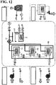
- the "reaction section” includes a first reactor R1, a second reactor R2, and a third reactor R3 that are independent of each other.
- the "condensing section” includes a first condenser D1, a second condenser D2, and a third condenser D3 that are independent of each other.
- the "connecting section” includes a "pipe G1 connecting R1 and D1", a “pipe G2 connecting R2 and D2", and a “pipe G3 connecting R3 and D3".
- "Valves” include a “valve V1 for opening and closing G1", a “valve V2 for opening and closing G2", and a “valve V3 for opening and closing G3".
- Fig. 1 The sections indicated by bold lines in Fig. 1 are spaces that are controlled to a pressure lower than the atmospheric pressure at room temperature with corresponding vacuum pumps VP after the pump has been assembled (before operation) and are then sealed (the same applies to Figs. 10 , 12 , and 18 , which will be described later).
- R1, R2, and R3 contain or are filled with the powder of a first heat storage material M1, the powder of a second heat storage material M2, and the powder of a third heat storage material M3, respectively.
- M1, M2, and M3 are disposed at different positions in the "reaction section".
- Each of M1, M2, and M3 has: "a property of dissipating heat while being converted into a hydrate by an exothermic reaction with water vapor" (first property); and “a property of storing heat while releasing water vapor and thus being dehydrated by an endothermic reaction of the hydrate caused by receiving external heat” (second property).
- the conversion temperature of a heat storage material depends on the material and also varies depending on the ambient pressure around the heat storage material.
- M1, M2, and M3 are typically CaO, MgO, and CaSO 4 , respectively.
- CaO, MgO, and CaSO 4 are involved in the reactions expressed by the following formulas (1), (2), and (3), respectively.
- "Q" represents thermal energy.
- Ca(OH) 2 is a hydrate of CaO.
- Mg(OH) 2 is a hydrate of MgO.
- CaSO 4 ⁇ 1/2H 2 O is a hydrate of CaSO 4 .
- R1, R2, and R3 each contain a heat exchanger E including a meandering flow channel.
- the heat exchanger E in R1 is surrounded by the aggregate of powder particles of M1 contained in R1.
- the heat exchanger E in R2 is surrounded by the aggregate of powder particles of M2 contained in R2.
- the heat exchanger E in R3 is surrounded by the aggregate of powder particles of M3 contained in R3.
- the first side of the heat exchanger E in R1 is connected to an opening H1 of a pipe, and a second side of the heat exchanger E in R1 is connected to the first side of the heat exchanger E in R2 with a pipe F1 therebetween.
- the second side of the heat exchanger E in R2 is connected to the first side of the heat exchanger E in R3 with a pipe F2 therebetween, and the second side of the heat exchanger E in R3 is connected to an opening H2 of a pipe.
- the "first fluid passage” is a continuous flow channel formed by connecting the member defining the opening H1, the heat exchanger E in R1, the pipe F1, the heat exchanger E in R2, the pipe F2, the heat exchanger E in R3, and the member defining the opening H2 in this order.
- the "first side” of the “first fluid flow channel” corresponds to the opening H1
- the "second side” of the "first fluid flow channel” corresponds to the opening H2.
- the first embodiment is configured so that the fluid flowing in the "first fluid passage" can perform heat exchanges with heat storage materials in such a manner that the higher the conversion temperature of the heat storage material, the closer the heat exchange position to the first side of the "first fluid flow channel".
- D1, D2, and D3 each contain water (or water vapor). Also, D1, D2, and D3 each contain the above-described heat exchanger E.
- the heat exchangers E in D1, D2, and D3 are immersed in water contained in D1, D2, and D3, respectively.
- heat exchange can be performed "between the fluid flowing in the heat exchanger E in D1 and water contained in D1", "between the fluid flowing in the heat exchanger E in D2 and water contained in D2", and "between the fluid flowing in the heat exchanger E in D3 and water contained in D3".
- the first side of the heat exchanger E in D1 is connected to an open end C11 of a pipe, and the second side of the heat exchanger E in D1 is connected to an open end C21 of a pipe.
- the first side of the heat exchanger E in D2 is connected to an open end C12 of a pipe, and the second side of the heat exchanger E in D2 is connected to an open end C22 of a pipe.
- the first side of the heat exchanger E in D3 is connected to an open end C13 of a pipe, and the second side of the heat exchanger E in D3 is connected to an open end C23 of a pipe.
- a "second fluid passage” corresponds to a “continuous flow channel formed by connecting the open end C11, the heat exchanger E in D1, and the open end C21 in this order", a “continuous flow channel formed by connecting the open end C12, the heat exchanger E in D2, and the open end C22 in this order", and a “continuous flow channel formed by connecting the open end C13, the heat exchanger E in D3, and the open end C23 in this order".
- Fig. 2 illustrates an exemplary structure of the first embodiment shown in its entirety in Fig. 1 .
- the structure shown in Fig. 2 is assembled in accordance with the following procedure.
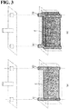
- heat exchangers E are prepared as shown in Fig. 3 .
- Each heat exchanger E has an opening E1 to be in communication with the first side of a "meandering flow channel" formed within a plate portion of the heat exchanger and an opening E2 to be in communication with the second side of the flow channel.
- Fig. 3(a) shows an example of a heat exchanger E including a single plate portion
- Fig. 3(b) shows an example of a heat exchanger E including three plate portions.
- Fig. 4(a) and 4(b) show a state where the heat exchanger E shown in Fig. 3(a) is contained and a state where the heat exchanger shown in Fig. 3(b) is contained, respectively.
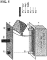
- the internal space of the substrate A containing the heat exchanger E is filled with any one of the powders of heat storage materials (M1, M2, and M3) or water (W1, W2, or W3), as shown in Fig. 5 .
- the heat exchanger E is surrounded by the aggregate of powder particles of the heat storage material or immersed in water.
- a lid B is joined to the top of the substrate A so as to seal the open top of the substrate in an air tight manner, as shown in Fig. 6 .
- the openings E1 and E2 are exposed in hole portions B1 and B2, respectively formed on the lid B.
- a pipe B3 protruding upward from the lid B communicates with the internal space of the substrate A.
- the joined body containing the first heat storage material M1, the joined body containing the second heat storage material M2, and the joined body containing the third heat storage material M3 act as the first reactor R1, the second reactor R2, and the third reactor R3, respectively.
- the joined bodies each containing water (W1, W2, or W3) act as the first condenser D1, the second condenser D2, and the third condenser D3, respectively.
- the opening E2 exposed at the top of R1 and the opening E2 exposed at the top of R2 are connected in an air tight manner with a pipe F1 therebetween, and the opening E1 exposed at the top of R2 and the opening E1 exposed at the top of R3 are connected in an air tight manner with a pipe F2 therebetween, as shown in Fig. 7 .
- Valves V1, V2, and V3 are provided in G1, G2, and G3, respectively.
- V1, V2, and V3 are configured to open and close G1, G2, and G3, respectively.
- the opening E1 exposed at the top of R1 corresponds to the opening H1
- the opening E2 exposed at the top of R3 corresponds to the opening H2.
- the openings E1 and E2 exposed at the top of D1 correspond to the open ends C11 and C21, respectively
- the openings E1 and E2 exposed at the top of D2 correspond to the open ends C12 and C22, respectively
- the openings E1 and E2 exposed at the top of D3 correspond to the open ends C13 and C23, respectively.
- a high-temperature gas for example, exhaust gas from a factory
- a high-temperature gas for example, exhaust gas from a factory
- the high-temperature gas introduced through the opening H2 passes through the heat exchanger E in R1, the heat exchanger E in R2, and the heat exchanger E in R3, in this order, and is then discharged through the opening H2.
- Water vapor (gas) generated by the dehydration flows from R1 to D1 through pipe G1.
- the water vapor that has reached D1 is converted into water (liquid) by phase transition (condensation), and the water is stored in D1.
- the high-temperature gas passing through the heat exchanger E in R1 is deprived of heat by the "endothermic reaction” (see formulas (1)).
- the temperature of the high-temperature gas that has passed through the heat exchanger E in R1 is thus reduced from the temperature before passing through the heat exchanger E.
- Water vapor (gas) generated by the dehydration flows from R2 to D2 through pipe G2.
- the water vapor that has reached D2 is converted into water (liquid) by phase transition (condensation), and the water is stored in D2.
- the high-temperature gas passing through the heat exchanger E in R2 is deprived of heat by the "endothermic reaction” (see formulas (2)).
- the temperature of the high-temperature gas that has passed through the heat exchanger E in R2 is thus reduced from the temperature before passing through the heat exchanger E.
- Water vapor (gas) generated by the dehydration flows from R3 to D3 through pipe G3.
- the water vapor that has reached D3 is converted into water (liquid) by phase transition (condensation), and the water is stored in D3.
- the high-temperature gas passing through the heat exchanger E in R3 is deprived of heat by the "endothermic reaction” (see formulas (3)). The temperature of the high-temperature gas that has passed through the heat exchanger E in R3 is thus reduced from the temperature before passing through the heat exchanger E.
- each of the conversion temperatures of the heat storage materials M1, M2, and M3, which vary depending on the ambient pressure, must be controlled (for example, so as to be kept constant). More specifically, in the heat storage mode, water in the condensers D1, D2, and D3 receives condensation heat generated by phase transition (condensation) of water from vapor. Therefore the temperatures of water in D1, D2, and D3 rise unless controlled. If the temperatures of water in D1, D2, and D3 rise, the vapor pressure of water increases, and the ambient pressures around the heat storage materials M1, M2, and M3 in the reactors R1, R2, and R3 increase accordingly. If the ambient pressures increase, the conversion temperatures of M1, M2, and M3 each increase.
- D1, D2, and D3 are each provided with the above-described "second fluid passage".
- a fluid such as water is run through the "second fluid passages".
- the "second fluid passages" are connected to a cooling device K, as shown in Fig. 2 .
- a warmed fluid coming from the first side (C11, C12, C13) of each "second fluid passage” is cooled with a motor-driven fan, and the cooled fluid is introduced to the corresponding "second fluid passage" through the second side (C21, C22, C23) thereof with a pump.
- the water in each of D1, D2, and D3 is cooled by heat exchange with the fluid flowing in the corresponding "second fluid passage".
- the temperatures of water in D1, D2, and D3 are controlled (for example, so as to be kept constant).
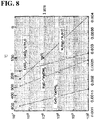
- the ambient pressures in R1, R2, and R3 are controlled to a predetermined pressure, for example, less than 1 atm by controlling the temperatures of water in D1, D2, and D3, the conversion temperatures of M1, M2, and M3 are kept at, for example, 372°C, 143°C, and 100°C, respectively, as shown in Fig. 9 .
- a state is established where the gas flowing in the first fluid passage from H1 to H2 has temperatures higher than 372°C, 143°C, and 100°C in the heat exchangers E in R1, R2, and R3, respectively
- heat can be stored in all the heat storage materials M1, M2, and M3.
- the temperatures of the gas in the heat exchangers E in R1 and R2 can be lower than the conversion temperatures of M1 and M2. Even in such a case, the temperature of the gas in the heat exchanger E in R3 can be higher than the conversion temperature of M3, which has a relatively low conversion temperature. Thus, even if a gas having a relatively low temperature is introduced from the opening H1, heat can be stored in at least one heat storage material having a relatively low conversion temperature.
- valves V1, V2, and V3 are closed.
- water vapor generated from the water in the condensers D1, D2, and D3 is prevented from flowing to the reactors R1, R2, and R3.
- "exothermic reactions" of M1, M2, and M3 do not occur.
- a low-temperature gas for example, room-temperature gas
- a low-temperature gas for example, room-temperature gas
- the low-temperature gas introduced through the opening H2 passes through the heat exchanger E in R3, the heat exchanger E in R2, and the heat exchanger E in R1, in this order, and is then discharged through the opening H1.
- each of the conversion temperatures of the heat storage materials M1, M2, and M3, which vary depending on the ambient pressure, must be controlled (for example, so as to be kept constant). More specifically, in the heat dissipation mode, the water in the condensers D1, D2, and D3 is deprived of heat caused by phase transition (vaporization) of water to vapor. Therefore the temperatures of water in D1, D2, and D3 decrease, unless controlled. If the temperatures of water in D1, D2, and D3 decrease, the vapor pressure of water decreases, and the ambient pressures around the heat storage materials M1, M2, and M3 in the reactors R1, R2, and R3 decrease accordingly. If the ambient pressures decrease, the conversion temperatures of M1, M2, and M3 each decrease.
- a fluid is introduced into the "second fluid passages" provided for D1, D2, and D3 to control the temperatures of water in D1, D2, and D3 (for example, so as to be kept constant).
- the "second fluid passages" are connected to a heating device L, as shown in Fig. 2 .
- a cooled fluid coming from the first side (C11, C12, C13) of each "second fluid passage” is warmed by using the heat of warm water stored in a warm water tank, and the warmed fluid is introduced to each "second fluid passage" through the second side (C21, C22, C23) thereof with a pump.
- the water in each of D1, D2, and D3 is warmed by heat exchange with the fluid flowing in the corresponding "second fluid passage".
- the temperatures of water in D1, D2, and D3 are controlled (for example, so as to be kept constant).
- the warm water in the warm water tank is deprived of heat by the fluid flowing in the "second fluid passage". Since the water in the warm water tank is thus cooled, cold water can be taken out of the warm water tank.
- the ambient pressures in R1, R2, and R3 are controlled to a constant pressure of, for example, 1 atm by controlling the temperatures of water in D1, D2, and D3, the conversion temperatures of M3, M2, and M1 are kept at 138°C, 227°C, and 484°C, respectively, as shown in Fig. 9 .
- heat can be dissipated from all the heat storage materials M3, M2, and M1.
- the temperature of the gas discharged from the "first fluid passage" through the opening H1 can be raised up to 484°C.
- the second embodiment is different from the first embodiment only in that the "condensing section" is constituted of only a single condenser D1 whereas the "condensing section” in the first embodiment is constituted of independent condensers D1, D2, and D3.
- the "connecting section" of the second embodiment is constituted of only a pipe G1.
- the pipe G1 connects D1 to "R1, R2, and R3". More specifically, the pipe B3 protruding from the top of D1 is connected in an air tight manner to each of the "pipes B3 protruding from the tops of R1, R2, and R3", as shown in Fig. 11 .
- R1, R2, and R3 are thus connected to the single D1. Therefore the ambient pressures in R1, R2, and R3 (hence, conversion temperatures of M1, M2, and M3) cannot be independently controlled, unlike the first embodiment. However since the number of condensers and pipes is smaller than in the case of the first embodiment, the structure can be simplified and, accordingly, the manufacturing cost can be reduced.
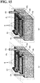
- the third embodiment is the same as the second embodiment in that the "condensing section" is constituted of only a single condenser D1.
- the third embodiment is, however, different from the second embodiment only in that the reactors R1, R2, and R3 constituting the "reaction section" is enclosed in a single container RR whereas the second embodiment uses reactors R1, R2, and R3 that are independent of each other.
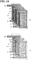
- tops of R1, R2, and R3 in the container RR are open, as shown particularly in Figs. 16 and 17 .
- R1, R2, and R3 are not covered with the independent lids B.
- a single large lid B is joined to the top of the container RR so as to cover the entity of the top of the container RR in an air tight manner.
- the pipe B3 protruding from the top of D1 is connected in an air tight manner to the pipe B3 protruding from the top of RR with the pipe G1 therebetween, as shown in Fig. 13 .
- the number of pipes exposed at the top of portions corresponding to the "reaction section" is smaller than that in the second embodiment. Accordingly, the appearance is better than that in the second embodiment.
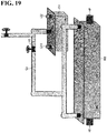
- the fourth embodiment is different from the third embodiment in that "three heat exchangers E connected in series" contained in a container RR are used as reactors R1, R2, and R3 whereas the heat exchangers E in the reactors R1, R2, and R3 of the third embodiment are each used as a portion of the "first fluid passage".
- the internal spaces of the three heat exchangers used as reactors R1, R2, and R3 in the container RR are filled with heat storage materials M1, M2, and M3, respectively, as shown in Figs. 20 and 21 .
- a single large lid B is joined to the top of the container RR so as to cover the entirety of the open top of the container RR in an air tight manner.
- the internal space of the container RR except the regions for the three heat exchangers E is used as a "first fluid flow channel".
- “a portion close to the reactor R1 in the internal space of the container RR” communicates with "the opening H1 provided for RR”
- "a portion close to the reactor R3 in the internal space of the container RR” communicates with "the opening H2 provided for RR”.
- the "first fluid passage” is a continuous flow channel formed by connecting a member defining the opening H1, "the internal space of the container RR except the regions for the three heat exchangers E", and a member defining the opening H2 in this order.
- the "first side” of the "first fluid passage” corresponds to the opening H1
- the "second side” of the "first fluid passage” corresponds to the opening H2.
- the present invention is not limited to the disclosed embodiments and various modifications may be made within the scope of the invention.
- the "plurality of heat storage materials” may be defined by two heat storage materials having different conversion temperatures, or four or more heat storage materials having different conversion temperatures, while the above embodiments each use three heat storage materials having different conversion temperatures.
- first fluid passage may be defined by a plurality of passages continuously connected in parallel, while the “first fluid passage” in the above embodiments is defined by a continuous single passage.
- CaCl 2 may be used as M3, instead of CaSO 4 .
- the use of CaCl 2 can produce the same effects as in the above embodiments.
- CaCl 2 is involved in the following reactions expressed by the following formulas (4):
- Q represents thermal energy
- n represents a natural number.
- CaCl 2 ⁇ n H 2 O is a hydrate of CaCl 2 .
- Heat storage materials having the "property of dissipating heat while being converted into a carbonated compound by an exothermic reaction with carbon dioxide” (third property) and the “property of storing heat while releasing carbon dioxide to be decarbonated by an endothermic reaction of the carbonated compound produced by receiving external heat” (fourth property) may be used as the plurality of heat storage materials having different transition temperatures, while the above embodiments use heat storage materials having the first property and the second property.
- Heat storage materials M1 and M2 having different conversion temperatures and having the third and the fourth property may be CaO and PbO.
- CaO and PbO are involved in the reactions expressed by the following formulas (5) and (6), respectively.
- "Q" represents thermal energy.
- CaCO 3 is a carbonated compound of CaO; in formulas (6), PbCO 3 is a carbonated compound of PbO.
- the reactor is charged with the powder of a heat storage material by introducing the powder of the heat storage material itself into the reactor, as shown in Figs. 5 , 16 , and 20 .
- the reactor is filled with an aggregate of closely packed powder particles of the heat storage material.
- the reactor is filled with an aggregate of closely packed powder particles of a heat storage material, the aggregate is likely to have a portion in which exothermic reaction does not easily occur, as described above. This implies that there is room for further increasing the exothermic reaction speed of the heat storage material as a whole (amount per unit time of the heat storage material that can react with water vapor).
- water vapor generated from the portion of the powder located close to the upper lid of the reactor by the endothermic reaction easily flows to the connecting section through the top of the reactor.
- the water vapor In order for water vapor generated from the portion of the powder located distant from the upper lid of the reactor to flow to the top of the reactor, the water vapor must move to the upper side so as to penetrate spaces among particles of the closely packed powder in a meandering manner. Thus, the water vapor does not easily flow and is likely to be saturated accordingly. Consequently, endothermic reaction is unlikely to occur in the portion of the powder located distant from the upper lid of the reactor.
- the reactor is filled with an aggregate of closely packed powder particles of a heat storage material, the aggregate is likely to have a portion in which endothermic reaction does not easily occur, as described above. This implies that there is room for further increasing the endothermic reaction speed of the heat storage material as a whole (amount per unit time of the heat storage material from which vapor is released).
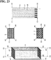
- the "heat storage material container” shown in Fig. 23 is intended to address this issue.
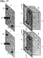
- the main body includes a frame Q extending in the longitudinal direction having inner holes passing in the longitudinal direction therein, and partition walls S separating the inner holes from each other so as to define "a plurality of flow channels extending parallel to each other in the longitudinal direction".
- the frame Q has a rectangular section, and the partition walls S are arranged so as to divide the rectangular section into a plurality of segments in a matrix manner.
- the partition walls S are made of a porous material.
- first flow channels U1 each having an upper open end and a lower end closed with a stop member T in the longitudinal direction thereof
- second flow channels U2 each having an upper open end and a lower open end in the longitudinal direction thereof
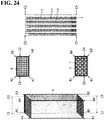
- the plurality of first flow channels U1 are charged with a heat storage material (M1, M2, or M3) while the plurality of second flow channels U2 are not charged with the heat storage material (M1, M2, or M3), as shown in Fig. 24 .
- the powder of the heat storage material can be introduced into the container shown in Fig. 23 from the top of the container so as to raise the level of the powder. Both the upper ends of the first flow channels U1 and the second flow channels U2 are open. Therefore the introduced powder runs down through both the first and the second flow channels U1 and U2 by force of gravity. The lower end of U1 is closed, while the lower end of U2 is open.
- a plurality of such containers in which only the plurality of U1 are filled with a heat storage material, are thus prepared.
- These containers are substituted for the powders of the heat storage materials shown in Figs. 5 , 16 , and 20 and arranged in the reactor (more specifically, in the internal space of the reactor except the regions for the heat exchangers).
- the water vapor that has entered U2 flows from the upper side toward the lower side in U2, thus flowing through the whole of U2 from the upper side to the lower side.
- the water vapor that has reached U2 easily enters U2 through the upper end of U2 and flows to the connecting section through the top of the reactor. This suggests that the aggregate is unlikely to have a portion in which the endothermic reaction does not easily occur.
- an arrangement of a plurality of "containers charged with the heat storage material" shown in Fig. 24 within a reactor is expected to increase the reaction speeds of the exothermic reaction and the endothermic reaction. Accordingly, it is expected that the efficiency of heat exchange between the fluid flowing in the "first fluid passage" and the heat storage material will be increased, and that the energy efficiency of the chemical heat pump will be increased as a whole.
- the partition walls S are made of the same material as "the heat storage material in the container". Consequently, the amount of the heat storage material present in the reactor is increased, and accordingly the overall amount of reaction involved in the heat exchange in the chemical heat pump is increased compared to the case of using other materials.
- the material of the partition walls S is preferably SiC or C.
- SiC and C are materials having a relatively high thermal conductivity. Therefore the thermal efficiency of the heat exchange between the fluid flowing in the "first fluid passage" and the heat storage material can be increased.
- the first flow channels U1 and the second flow channels U2 are disposed so as to be alternately arranged *in a matrix manner at the section of the frame Q.
- the arrangement of the flow channels is not necessarily in an alternate manner as long as at least one second flow channel U2 is present.
- the present invention can be applied to the industrial field of manufacture of heat storage material containers.
Claims (6)
- Contenant pour matériau de stockage de chaleur (R1, R2, R3) comprenant :un corps principal ayant une direction longitudinale et comprenant une pluralité de canaux d'écoulement (U1, U2) en son sein, les canaux d'écoulement s'étendant parallèlement les uns par rapport aux autres dans la direction longitudinale et étant séparés les uns des autres par des parois poreuses (S) ; etun matériau de stockage de chaleur (M1, M2, M3) contenu dans uniquement un ou certains de la pluralité de canaux d'écoulement,dans lequel la pluralité de canaux d'écoulement comprend une pluralité de premiers canaux d'écoulement (U1) ayant chacun une extrémité ouverte sur un premier côté dans la direction longitudinale et une extrémité fermée sur un second côté dans la direction longitudinale, et caractérisé parune pluralité de seconds canaux d'écoulement (U2) ayant chacun des extrémités ouvertes à la fois sur le premier côté et le second côté dans la direction longitudinale, etdans lequel le matériau de stockage de chaleur (M1, M2, M3) est contenu dans uniquement les premiers canaux d'écoulement (U1) sans être contenu dans les seconds canaux d'écoulement (U2).
- Contenant selon la revendication 1,
dans lequel les premiers canaux d'écoulement (U1) et les seconds canaux d'écoulement (U2) sont arrangés de manière alternée lorsqu'ils sont visualisés dans la direction longitudinale. - Contenant selon la revendication 1 ou la revendication 2,
dans lequel les parois poreuses (S) sont constituées du même matériau que le matériau de stockage de chaleur (M1, M2, M3) contenu. - Contenant selon la revendication 1 ou la revendication 2,
dans lequel les parois poreuses (S) sont en SiC ou C. - Contenant selon l'une quelconque des revendications 1 à 4, dans lequel le matériau de stockage de chaleur a :comme première propriété, une propriété de dissipation de chaleur tout en étant converti en un hydrate par une réaction exothermique avec de la vapeur d'eau ; etcomme seconde propriété, une propriété de stockage de chaleur tout en libérant de la vapeur d'eau et par conséquent en étant déshydraté par une réaction endothermique de l'hydrate provoquée par la réception d'une chaleur externe.
- Contenant selon l'une quelconque des revendications 1 à 5, dans lequel le matériau de stockage de chaleur est un ou plusieurs parmi CaO, MgO et CaSO4.
Applications Claiming Priority (2)
| Application Number | Priority Date | Filing Date | Title |
|---|---|---|---|
| JP2014227754 | 2014-11-10 | ||
| PCT/JP2015/078114 WO2016076035A1 (fr) | 2014-11-10 | 2015-10-02 | Récipient contenant un matériau de stockage thermique |
Publications (3)
| Publication Number | Publication Date |
|---|---|
| EP3093603A1 EP3093603A1 (fr) | 2016-11-16 |
| EP3093603A4 EP3093603A4 (fr) | 2017-09-27 |
| EP3093603B1 true EP3093603B1 (fr) | 2018-11-28 |
Family
ID=55954128
Family Applications (1)
| Application Number | Title | Priority Date | Filing Date |
|---|---|---|---|
| EP15858204.9A Active EP3093603B1 (fr) | 2014-11-10 | 2015-10-02 | Récipient contenant un matériau de stockage thermique |
Country Status (4)
| Country | Link |
|---|---|
| US (1) | US10359236B2 (fr) |
| EP (1) | EP3093603B1 (fr) |
| JP (1) | JP6674378B2 (fr) |
| WO (1) | WO2016076035A1 (fr) |
Family Cites Families (40)
| Publication number | Priority date | Publication date | Assignee | Title |
|---|---|---|---|---|
| EP0053737B1 (fr) * | 1980-11-13 | 1987-01-14 | Sekisui Kagaku Kogyo Kabushiki Kaisha | Dispositif de pompe à chaleur |
| US4422500A (en) * | 1980-12-29 | 1983-12-27 | Sekisui Kagaku Kogyo Kabushiki Kaisha | Metal hydride heat pump |
| US4402915A (en) * | 1981-05-06 | 1983-09-06 | Sekisui Kagaku Kogyo Kabushiki Kaisha | Metal hydride reactor |
| JP2746943B2 (ja) * | 1988-10-03 | 1998-05-06 | 工業技術院長 | 蓄熱器 |
| US4928496A (en) * | 1989-04-14 | 1990-05-29 | Advanced Materials Corporation | Hydrogen heat pump |
| NL9102072A (nl) * | 1991-12-11 | 1993-07-01 | Beijer Raadgevend Tech Bureau | Warmteaccumulator, werkwijze voor de vervaardiging daarvan, alsmede energiesysteem voorzien van een dergelijke warmteaccumulator. |
| JP3340287B2 (ja) * | 1995-09-13 | 2002-11-05 | 新日本製鐵株式会社 | 蓄熱式バーナーの蓄熱体 |
| JPH1151583A (ja) * | 1997-08-05 | 1999-02-26 | Tokyo Gas Co Ltd | 蓄熱体並びに蓄熱式熱交換器および蓄熱型燃焼装置 |
| JPH11264683A (ja) * | 1998-03-18 | 1999-09-28 | Ishikawajima Harima Heavy Ind Co Ltd | 蓄熱形熱交換器 |
| JP4671501B2 (ja) * | 2000-11-29 | 2011-04-20 | 京セラ株式会社 | 軽量セラミックス部材およびその製造方法 |
| JP4216174B2 (ja) * | 2003-01-09 | 2009-01-28 | 日本碍子株式会社 | コート材、セラミックスハニカム構造体及びその製造方法 |
| JP4205450B2 (ja) * | 2003-02-19 | 2009-01-07 | 本田技研工業株式会社 | 蓄熱装置用エレメント及び蓄熱装置の製造方法 |
| JP4142499B2 (ja) * | 2003-05-30 | 2008-09-03 | 株式会社神戸製鋼所 | 連通多孔質層と緻密層を有するセラミックス焼結体の製造方法 |
| US7581698B2 (en) * | 2004-04-23 | 2009-09-01 | Airbus Deutschland Gmbh | Method and apparatus for tempering gaseous and/or liquid media in transportation vehicles, particularly in aircraft |
| US7814426B2 (en) * | 2004-06-30 | 2010-10-12 | Sap Aktiengesellschaft | Reusable component in a collaboration workspace |
| US7781109B2 (en) * | 2004-09-03 | 2010-08-24 | Gross Karl J | Hydrogen storage and integrated fuel cell assembly |
| US7222659B2 (en) * | 2005-04-12 | 2007-05-29 | Alexander Levin | Heat and cold storage multistage tower with application of PCM |
| DE102005018307A1 (de) * | 2005-04-20 | 2006-10-26 | Arvinmeritor Emissions Technologies Gmbh | Abgasanlage für ein Kraftfahrzeug |
| JP5531334B2 (ja) | 2006-07-18 | 2014-06-25 | 国立大学法人 千葉大学 | ケミカルヒ−トポンプコンテナ |
| WO2008129671A1 (fr) * | 2007-04-17 | 2008-10-30 | Ibiden Co., Ltd. | Nid d'abeille porteur de catalyseur et processus de production de ce nid d'abeille |
| JP4911002B2 (ja) * | 2007-11-30 | 2012-04-04 | 株式会社豊田中央研究所 | 熱交換型熱利用装置及びその製造方法 |
| JP5374683B2 (ja) * | 2008-03-14 | 2013-12-25 | 株式会社豊田中央研究所 | 化学蓄熱材成形体及びその製造方法 |
| DE102008040451A1 (de) * | 2008-07-16 | 2010-01-21 | Robert Bosch Gmbh | Partikelfilter, Verfahren zum Betrieb und Verfahren zur Herstellung eines solchen Partikelfilters |
| JP2010269978A (ja) * | 2009-05-22 | 2010-12-02 | Aisin Takaoka Ltd | 蓄熱燃焼装置用ハニカム蓄熱体及びその製造方法 |
| JP5439089B2 (ja) * | 2009-08-18 | 2014-03-12 | 日本碍子株式会社 | ハニカム構造体の製造方法 |
| JP2011038750A (ja) * | 2009-08-18 | 2011-02-24 | Ngk Insulators Ltd | ハニカム型潜熱蓄熱体 |
| JP2011052919A (ja) * | 2009-09-03 | 2011-03-17 | Ngk Insulators Ltd | 蓄熱体 |
| JP5413963B2 (ja) * | 2009-09-07 | 2014-02-12 | 住化スタイロンポリカーボネート株式会社 | 積層体 |
| JP2011058678A (ja) * | 2009-09-08 | 2011-03-24 | Ngk Insulators Ltd | 蓄熱構造体 |
| DE102010004358A1 (de) * | 2010-01-12 | 2011-06-16 | Deutsches Zentrum für Luft- und Raumfahrt e.V. | Latentwärmespeicher |
| MX339872B (es) * | 2010-01-12 | 2016-06-15 | Sylvan Source Inc | Interfaz de transferencia termica. |
| US9120959B2 (en) * | 2010-03-25 | 2015-09-01 | Kabushiki Kaisha Toyota Chuo Kenkyusho | Chemical thermal energy storage material structure, method of producing the same, and chemical heat accumulator |
| KR20130016687A (ko) * | 2011-08-08 | 2013-02-18 | 주식회사 칸세라 | 제철소 가열로용 허니컴 축열체 |
| JP5852872B2 (ja) * | 2011-12-15 | 2016-02-03 | 日本碍子株式会社 | 蓄熱構造体 |
| US8702851B2 (en) * | 2012-03-02 | 2014-04-22 | Hamilton Sundstrand Space Systems International, Inc. | Heat exchanger |
| JP6016208B2 (ja) | 2012-03-21 | 2016-10-26 | 国立大学法人 千葉大学 | ケミカルヒートポンプ及びその制御方法 |
| JP2013253212A (ja) * | 2012-06-08 | 2013-12-19 | Shibaura Institute Of Technology | 化学蓄熱材成形体およびその製造方法ならびに化学蓄熱装置 |
| JP6232196B2 (ja) * | 2013-03-21 | 2017-11-15 | 株式会社豊田中央研究所 | 箱体、化学蓄熱反応器及び化学蓄熱システム |
| JP2014227754A (ja) | 2013-05-24 | 2014-12-08 | 北川工業株式会社 | 橋桁および橋桁の施工方法 |
| JP2013234669A (ja) * | 2013-07-08 | 2013-11-21 | Ngk Insulators Ltd | 蓄熱構造体 |
-
2015
- 2015-10-02 EP EP15858204.9A patent/EP3093603B1/fr active Active
- 2015-10-02 WO PCT/JP2015/078114 patent/WO2016076035A1/fr active Application Filing
- 2015-10-02 JP JP2016538151A patent/JP6674378B2/ja active Active
-
2016
- 2016-06-10 US US15/178,947 patent/US10359236B2/en active Active
Also Published As
| Publication number | Publication date |
|---|---|
| EP3093603A1 (fr) | 2016-11-16 |
| EP3093603A4 (fr) | 2017-09-27 |
| US10359236B2 (en) | 2019-07-23 |
| JPWO2016076035A1 (ja) | 2017-08-17 |
| WO2016076035A1 (fr) | 2016-05-19 |
| US20160282056A1 (en) | 2016-09-29 |
| JP6674378B2 (ja) | 2020-04-01 |
Similar Documents
| Publication | Publication Date | Title |
|---|---|---|
| US10451323B2 (en) | Chemical heat pump | |
| JP5077419B2 (ja) | 化学蓄熱装置 | |
| CN107771365B (zh) | 中空纤维膜组件 | |
| AU2007268277B2 (en) | Chemical heat pump working with a hybrid substance | |
| EP3252417B1 (fr) | Récipient de stockage de chaleur et dispositif de stockage de chaleur pourvu de ce récipient de stockage de chaleur | |
| EP2749831B1 (fr) | Réacteur de stockage de chaleur chimique et système de stockage de chaleur chimique | |
| EP3189293B1 (fr) | Système et procédé de stockage de l'énergie thermochimique | |
| JP2017218492A (ja) | 化学蓄熱材及び化学蓄熱材を使用した蓄熱容器 | |
| EP2543950A2 (fr) | Dissipateur thermique avec matériau à changement de phase | |
| EP3093603B1 (fr) | Récipient contenant un matériau de stockage thermique | |
| JP6422283B2 (ja) | 蓄熱容器及び蓄熱容器を備えた蓄熱装置 | |
| JP4752618B2 (ja) | 蓄熱システム | |
| KR102655968B1 (ko) | 연료전지 시스템 | |
| US10082248B2 (en) | Metal hydride device for storage and transportation of hydrogen | |
| JPH03247968A (ja) | ヒートポンプ | |
| KR101636315B1 (ko) | 기액분리를 위한 기화공간이 형성된 판형 열교환기 | |
| US20160290685A1 (en) | Heat storage and release unit, chemical heat pump, and non-electrified cooling unit | |
| JP6838475B2 (ja) | 化学蓄熱反応器、及び化学蓄熱反応器システム | |
| JP2017219234A (ja) | 蓄熱容器及び蓄熱容器を備えた蓄熱装置 | |
| US20160178284A1 (en) | Compact thermochemical reactor with optimised transfers and maintenance | |
| JP2011052911A (ja) | 蓄熱システムおよびその運転方法 | |
| JP6395622B2 (ja) | 蓄熱装置 | |
| JP6356480B2 (ja) | ホットモジュール | |
| Vasiliev et al. | Heat pipes− good tool for fuel cells thermal management | |
| JPS6231238B2 (fr) |
Legal Events
| Date | Code | Title | Description |
|---|---|---|---|
| PUAI | Public reference made under article 153(3) epc to a published international application that has entered the european phase |
Free format text: ORIGINAL CODE: 0009012 |
|
| 17P | Request for examination filed |
Effective date: 20160630 |
|
| AK | Designated contracting states |
Kind code of ref document: A1 Designated state(s): AL AT BE BG CH CY CZ DE DK EE ES FI FR GB GR HR HU IE IS IT LI LT LU LV MC MK MT NL NO PL PT RO RS SE SI SK SM TR |
|
| AX | Request for extension of the european patent |
Extension state: BA ME |
|
| A4 | Supplementary search report drawn up and despatched |
Effective date: 20170829 |
|
| RIC1 | Information provided on ipc code assigned before grant |
Ipc: F28F 23/00 20060101ALI20170823BHEP Ipc: F28D 20/00 20060101AFI20170823BHEP Ipc: F25B 17/08 20060101ALI20170823BHEP Ipc: F28D 20/02 20060101ALI20170823BHEP |
|
| DAV | Request for validation of the european patent (deleted) | ||
| DAX | Request for extension of the european patent (deleted) | ||
| GRAP | Despatch of communication of intention to grant a patent |
Free format text: ORIGINAL CODE: EPIDOSNIGR1 |
|
| STAA | Information on the status of an ep patent application or granted ep patent |
Free format text: STATUS: GRANT OF PATENT IS INTENDED |
|
| INTG | Intention to grant announced |
Effective date: 20180516 |
|
| GRAS | Grant fee paid |
Free format text: ORIGINAL CODE: EPIDOSNIGR3 |
|
| GRAA | (expected) grant |
Free format text: ORIGINAL CODE: 0009210 |
|
| STAA | Information on the status of an ep patent application or granted ep patent |
Free format text: STATUS: THE PATENT HAS BEEN GRANTED |
|
| AK | Designated contracting states |
Kind code of ref document: B1 Designated state(s): AL AT BE BG CH CY CZ DE DK EE ES FI FR GB GR HR HU IE IS IT LI LT LU LV MC MK MT NL NO PL PT RO RS SE SI SK SM TR |
|
| REG | Reference to a national code |
Ref country code: CH Ref legal event code: EP |
|
| REG | Reference to a national code |
Ref country code: AT Ref legal event code: REF Ref document number: 1070717 Country of ref document: AT Kind code of ref document: T Effective date: 20181215 |
|
| REG | Reference to a national code |
Ref country code: DE Ref legal event code: R096 Ref document number: 602015020666 Country of ref document: DE |
|
| REG | Reference to a national code |
Ref country code: IE Ref legal event code: FG4D |
|
| REG | Reference to a national code |
Ref country code: NL Ref legal event code: MP Effective date: 20181128 |
|
| REG | Reference to a national code |
Ref country code: LT Ref legal event code: MG4D |
|
| REG | Reference to a national code |
Ref country code: AT Ref legal event code: MK05 Ref document number: 1070717 Country of ref document: AT Kind code of ref document: T Effective date: 20181128 |
|
| PG25 | Lapsed in a contracting state [announced via postgrant information from national office to epo] |
Ref country code: NO Free format text: LAPSE BECAUSE OF FAILURE TO SUBMIT A TRANSLATION OF THE DESCRIPTION OR TO PAY THE FEE WITHIN THE PRESCRIBED TIME-LIMIT Effective date: 20190228 Ref country code: BG Free format text: LAPSE BECAUSE OF FAILURE TO SUBMIT A TRANSLATION OF THE DESCRIPTION OR TO PAY THE FEE WITHIN THE PRESCRIBED TIME-LIMIT Effective date: 20190228 Ref country code: FI Free format text: LAPSE BECAUSE OF FAILURE TO SUBMIT A TRANSLATION OF THE DESCRIPTION OR TO PAY THE FEE WITHIN THE PRESCRIBED TIME-LIMIT Effective date: 20181128 Ref country code: LT Free format text: LAPSE BECAUSE OF FAILURE TO SUBMIT A TRANSLATION OF THE DESCRIPTION OR TO PAY THE FEE WITHIN THE PRESCRIBED TIME-LIMIT Effective date: 20181128 Ref country code: IS Free format text: LAPSE BECAUSE OF FAILURE TO SUBMIT A TRANSLATION OF THE DESCRIPTION OR TO PAY THE FEE WITHIN THE PRESCRIBED TIME-LIMIT Effective date: 20190328 Ref country code: AT Free format text: LAPSE BECAUSE OF FAILURE TO SUBMIT A TRANSLATION OF THE DESCRIPTION OR TO PAY THE FEE WITHIN THE PRESCRIBED TIME-LIMIT Effective date: 20181128 Ref country code: ES Free format text: LAPSE BECAUSE OF FAILURE TO SUBMIT A TRANSLATION OF THE DESCRIPTION OR TO PAY THE FEE WITHIN THE PRESCRIBED TIME-LIMIT Effective date: 20181128 Ref country code: LV Free format text: LAPSE BECAUSE OF FAILURE TO SUBMIT A TRANSLATION OF THE DESCRIPTION OR TO PAY THE FEE WITHIN THE PRESCRIBED TIME-LIMIT Effective date: 20181128 Ref country code: HR Free format text: LAPSE BECAUSE OF FAILURE TO SUBMIT A TRANSLATION OF THE DESCRIPTION OR TO PAY THE FEE WITHIN THE PRESCRIBED TIME-LIMIT Effective date: 20181128 |
|
| PG25 | Lapsed in a contracting state [announced via postgrant information from national office to epo] |
Ref country code: GR Free format text: LAPSE BECAUSE OF FAILURE TO SUBMIT A TRANSLATION OF THE DESCRIPTION OR TO PAY THE FEE WITHIN THE PRESCRIBED TIME-LIMIT Effective date: 20190301 Ref country code: SE Free format text: LAPSE BECAUSE OF FAILURE TO SUBMIT A TRANSLATION OF THE DESCRIPTION OR TO PAY THE FEE WITHIN THE PRESCRIBED TIME-LIMIT Effective date: 20181128 Ref country code: AL Free format text: LAPSE BECAUSE OF FAILURE TO SUBMIT A TRANSLATION OF THE DESCRIPTION OR TO PAY THE FEE WITHIN THE PRESCRIBED TIME-LIMIT Effective date: 20181128 Ref country code: RS Free format text: LAPSE BECAUSE OF FAILURE TO SUBMIT A TRANSLATION OF THE DESCRIPTION OR TO PAY THE FEE WITHIN THE PRESCRIBED TIME-LIMIT Effective date: 20181128 Ref country code: PT Free format text: LAPSE BECAUSE OF FAILURE TO SUBMIT A TRANSLATION OF THE DESCRIPTION OR TO PAY THE FEE WITHIN THE PRESCRIBED TIME-LIMIT Effective date: 20190328 |
|
| PG25 | Lapsed in a contracting state [announced via postgrant information from national office to epo] |
Ref country code: NL Free format text: LAPSE BECAUSE OF FAILURE TO SUBMIT A TRANSLATION OF THE DESCRIPTION OR TO PAY THE FEE WITHIN THE PRESCRIBED TIME-LIMIT Effective date: 20181128 |
|
| PG25 | Lapsed in a contracting state [announced via postgrant information from national office to epo] |
Ref country code: PL Free format text: LAPSE BECAUSE OF FAILURE TO SUBMIT A TRANSLATION OF THE DESCRIPTION OR TO PAY THE FEE WITHIN THE PRESCRIBED TIME-LIMIT Effective date: 20181128 Ref country code: DK Free format text: LAPSE BECAUSE OF FAILURE TO SUBMIT A TRANSLATION OF THE DESCRIPTION OR TO PAY THE FEE WITHIN THE PRESCRIBED TIME-LIMIT Effective date: 20181128 Ref country code: CZ Free format text: LAPSE BECAUSE OF FAILURE TO SUBMIT A TRANSLATION OF THE DESCRIPTION OR TO PAY THE FEE WITHIN THE PRESCRIBED TIME-LIMIT Effective date: 20181128 Ref country code: IT Free format text: LAPSE BECAUSE OF FAILURE TO SUBMIT A TRANSLATION OF THE DESCRIPTION OR TO PAY THE FEE WITHIN THE PRESCRIBED TIME-LIMIT Effective date: 20181128 |
|
| REG | Reference to a national code |
Ref country code: DE Ref legal event code: R097 Ref document number: 602015020666 Country of ref document: DE |
|
| PG25 | Lapsed in a contracting state [announced via postgrant information from national office to epo] |
Ref country code: RO Free format text: LAPSE BECAUSE OF FAILURE TO SUBMIT A TRANSLATION OF THE DESCRIPTION OR TO PAY THE FEE WITHIN THE PRESCRIBED TIME-LIMIT Effective date: 20181128 Ref country code: EE Free format text: LAPSE BECAUSE OF FAILURE TO SUBMIT A TRANSLATION OF THE DESCRIPTION OR TO PAY THE FEE WITHIN THE PRESCRIBED TIME-LIMIT Effective date: 20181128 Ref country code: SM Free format text: LAPSE BECAUSE OF FAILURE TO SUBMIT A TRANSLATION OF THE DESCRIPTION OR TO PAY THE FEE WITHIN THE PRESCRIBED TIME-LIMIT Effective date: 20181128 Ref country code: SK Free format text: LAPSE BECAUSE OF FAILURE TO SUBMIT A TRANSLATION OF THE DESCRIPTION OR TO PAY THE FEE WITHIN THE PRESCRIBED TIME-LIMIT Effective date: 20181128 |
|
| PLBE | No opposition filed within time limit |
Free format text: ORIGINAL CODE: 0009261 |
|
| STAA | Information on the status of an ep patent application or granted ep patent |
Free format text: STATUS: NO OPPOSITION FILED WITHIN TIME LIMIT |
|
| PG25 | Lapsed in a contracting state [announced via postgrant information from national office to epo] |
Ref country code: SI Free format text: LAPSE BECAUSE OF FAILURE TO SUBMIT A TRANSLATION OF THE DESCRIPTION OR TO PAY THE FEE WITHIN THE PRESCRIBED TIME-LIMIT Effective date: 20181128 |
|
| 26N | No opposition filed |
Effective date: 20190829 |
|
| PG25 | Lapsed in a contracting state [announced via postgrant information from national office to epo] |
Ref country code: TR Free format text: LAPSE BECAUSE OF FAILURE TO SUBMIT A TRANSLATION OF THE DESCRIPTION OR TO PAY THE FEE WITHIN THE PRESCRIBED TIME-LIMIT Effective date: 20181128 |
|
| PG25 | Lapsed in a contracting state [announced via postgrant information from national office to epo] |
Ref country code: MC Free format text: LAPSE BECAUSE OF FAILURE TO SUBMIT A TRANSLATION OF THE DESCRIPTION OR TO PAY THE FEE WITHIN THE PRESCRIBED TIME-LIMIT Effective date: 20181128 |
|
| REG | Reference to a national code |
Ref country code: CH Ref legal event code: PL |
|
| PG25 | Lapsed in a contracting state [announced via postgrant information from national office to epo] |
Ref country code: LU Free format text: LAPSE BECAUSE OF NON-PAYMENT OF DUE FEES Effective date: 20191002 Ref country code: LI Free format text: LAPSE BECAUSE OF NON-PAYMENT OF DUE FEES Effective date: 20191031 Ref country code: CH Free format text: LAPSE BECAUSE OF NON-PAYMENT OF DUE FEES Effective date: 20191031 |
|
| REG | Reference to a national code |
Ref country code: BE Ref legal event code: MM Effective date: 20191031 |
|
| PG25 | Lapsed in a contracting state [announced via postgrant information from national office to epo] |
Ref country code: BE Free format text: LAPSE BECAUSE OF NON-PAYMENT OF DUE FEES Effective date: 20191031 |
|
| PG25 | Lapsed in a contracting state [announced via postgrant information from national office to epo] |
Ref country code: IE Free format text: LAPSE BECAUSE OF NON-PAYMENT OF DUE FEES Effective date: 20191002 |
|
| PG25 | Lapsed in a contracting state [announced via postgrant information from national office to epo] |
Ref country code: CY Free format text: LAPSE BECAUSE OF FAILURE TO SUBMIT A TRANSLATION OF THE DESCRIPTION OR TO PAY THE FEE WITHIN THE PRESCRIBED TIME-LIMIT Effective date: 20181128 |
|
| PG25 | Lapsed in a contracting state [announced via postgrant information from national office to epo] |
Ref country code: HU Free format text: LAPSE BECAUSE OF FAILURE TO SUBMIT A TRANSLATION OF THE DESCRIPTION OR TO PAY THE FEE WITHIN THE PRESCRIBED TIME-LIMIT; INVALID AB INITIO Effective date: 20151002 Ref country code: MT Free format text: LAPSE BECAUSE OF FAILURE TO SUBMIT A TRANSLATION OF THE DESCRIPTION OR TO PAY THE FEE WITHIN THE PRESCRIBED TIME-LIMIT Effective date: 20181128 |
|
| PG25 | Lapsed in a contracting state [announced via postgrant information from national office to epo] |
Ref country code: MK Free format text: LAPSE BECAUSE OF FAILURE TO SUBMIT A TRANSLATION OF THE DESCRIPTION OR TO PAY THE FEE WITHIN THE PRESCRIBED TIME-LIMIT Effective date: 20181128 |
|
| PGFP | Annual fee paid to national office [announced via postgrant information from national office to epo] |
Ref country code: GB Payment date: 20230831 Year of fee payment: 9 |
|
| PGFP | Annual fee paid to national office [announced via postgrant information from national office to epo] |
Ref country code: FR Payment date: 20230911 Year of fee payment: 9 |
|
| PGFP | Annual fee paid to national office [announced via postgrant information from national office to epo] |
Ref country code: DE Payment date: 20230830 Year of fee payment: 9 |