EP3088710A1 - Dispositif de commande et procédé de commande pour moteurs - Google Patents
Dispositif de commande et procédé de commande pour moteurs Download PDFInfo
- Publication number
- EP3088710A1 EP3088710A1 EP13900548.2A EP13900548A EP3088710A1 EP 3088710 A1 EP3088710 A1 EP 3088710A1 EP 13900548 A EP13900548 A EP 13900548A EP 3088710 A1 EP3088710 A1 EP 3088710A1
- Authority
- EP
- European Patent Office
- Prior art keywords
- engine
- control unit
- condition
- sensor
- transmission
- Prior art date
- Legal status (The legal status is an assumption and is not a legal conclusion. Google has not performed a legal analysis and makes no representation as to the accuracy of the status listed.)
- Granted
Links
- 238000000034 method Methods 0.000 title claims description 81
- 230000005540 biological transmission Effects 0.000 claims abstract description 66
- 230000007935 neutral effect Effects 0.000 claims abstract description 22
- 230000009467 reduction Effects 0.000 description 96
- 230000008569 process Effects 0.000 description 77
- 239000000446 fuel Substances 0.000 description 10
- 239000012530 fluid Substances 0.000 description 5
- 230000008859 change Effects 0.000 description 3
- 238000010586 diagram Methods 0.000 description 2
- 230000006872 improvement Effects 0.000 description 2
- 230000007246 mechanism Effects 0.000 description 2
- 230000004044 response Effects 0.000 description 2
- 230000002159 abnormal effect Effects 0.000 description 1
- 238000002485 combustion reaction Methods 0.000 description 1
- 239000002283 diesel fuel Substances 0.000 description 1
- 230000000694 effects Effects 0.000 description 1
- 230000006870 function Effects 0.000 description 1
- 238000002347 injection Methods 0.000 description 1
- 239000007924 injection Substances 0.000 description 1
- 230000001537 neural effect Effects 0.000 description 1
- 238000004092 self-diagnosis Methods 0.000 description 1
- 239000007858 starting material Substances 0.000 description 1
Images


Classifications
-
- F—MECHANICAL ENGINEERING; LIGHTING; HEATING; WEAPONS; BLASTING
- F02—COMBUSTION ENGINES; HOT-GAS OR COMBUSTION-PRODUCT ENGINE PLANTS
- F02D—CONTROLLING COMBUSTION ENGINES
- F02D17/00—Controlling engines by cutting out individual cylinders; Rendering engines inoperative or idling
-
- F—MECHANICAL ENGINEERING; LIGHTING; HEATING; WEAPONS; BLASTING
- F02—COMBUSTION ENGINES; HOT-GAS OR COMBUSTION-PRODUCT ENGINE PLANTS
- F02D—CONTROLLING COMBUSTION ENGINES
- F02D41/00—Electrical control of supply of combustible mixture or its constituents
- F02D41/02—Circuit arrangements for generating control signals
- F02D41/021—Introducing corrections for particular conditions exterior to the engine
- F02D41/0215—Introducing corrections for particular conditions exterior to the engine in relation with elements of the transmission
- F02D41/022—Introducing corrections for particular conditions exterior to the engine in relation with elements of the transmission in relation with the clutch status
-
- F—MECHANICAL ENGINEERING; LIGHTING; HEATING; WEAPONS; BLASTING
- F02—COMBUSTION ENGINES; HOT-GAS OR COMBUSTION-PRODUCT ENGINE PLANTS
- F02D—CONTROLLING COMBUSTION ENGINES
- F02D41/00—Electrical control of supply of combustible mixture or its constituents
- F02D41/02—Circuit arrangements for generating control signals
- F02D41/04—Introducing corrections for particular operating conditions
- F02D41/042—Introducing corrections for particular operating conditions for stopping the engine
-
- F—MECHANICAL ENGINEERING; LIGHTING; HEATING; WEAPONS; BLASTING
- F02—COMBUSTION ENGINES; HOT-GAS OR COMBUSTION-PRODUCT ENGINE PLANTS
- F02D—CONTROLLING COMBUSTION ENGINES
- F02D41/00—Electrical control of supply of combustible mixture or its constituents
- F02D41/02—Circuit arrangements for generating control signals
- F02D41/04—Introducing corrections for particular operating conditions
- F02D41/06—Introducing corrections for particular operating conditions for engine starting or warming up
- F02D41/062—Introducing corrections for particular operating conditions for engine starting or warming up for starting
- F02D41/065—Introducing corrections for particular operating conditions for engine starting or warming up for starting at hot start or restart
-
- F—MECHANICAL ENGINEERING; LIGHTING; HEATING; WEAPONS; BLASTING
- F02—COMBUSTION ENGINES; HOT-GAS OR COMBUSTION-PRODUCT ENGINE PLANTS
- F02D—CONTROLLING COMBUSTION ENGINES
- F02D41/00—Electrical control of supply of combustible mixture or its constituents
- F02D41/24—Electrical control of supply of combustible mixture or its constituents characterised by the use of digital means
- F02D41/2406—Electrical control of supply of combustible mixture or its constituents characterised by the use of digital means using essentially read only memories
-
- F—MECHANICAL ENGINEERING; LIGHTING; HEATING; WEAPONS; BLASTING
- F02—COMBUSTION ENGINES; HOT-GAS OR COMBUSTION-PRODUCT ENGINE PLANTS
- F02D—CONTROLLING COMBUSTION ENGINES
- F02D41/00—Electrical control of supply of combustible mixture or its constituents
- F02D41/24—Electrical control of supply of combustible mixture or its constituents characterised by the use of digital means
- F02D41/26—Electrical control of supply of combustible mixture or its constituents characterised by the use of digital means using computer, e.g. microprocessor
-
- F—MECHANICAL ENGINEERING; LIGHTING; HEATING; WEAPONS; BLASTING
- F02—COMBUSTION ENGINES; HOT-GAS OR COMBUSTION-PRODUCT ENGINE PLANTS
- F02N—STARTING OF COMBUSTION ENGINES; STARTING AIDS FOR SUCH ENGINES, NOT OTHERWISE PROVIDED FOR
- F02N11/00—Starting of engines by means of electric motors
- F02N11/08—Circuits or control means specially adapted for starting of engines
- F02N11/0814—Circuits or control means specially adapted for starting of engines comprising means for controlling automatic idle-start-stop
- F02N11/0818—Conditions for starting or stopping the engine or for deactivating the idle-start-stop mode
- F02N11/0822—Conditions for starting or stopping the engine or for deactivating the idle-start-stop mode related to action of the driver
-
- F—MECHANICAL ENGINEERING; LIGHTING; HEATING; WEAPONS; BLASTING
- F02—COMBUSTION ENGINES; HOT-GAS OR COMBUSTION-PRODUCT ENGINE PLANTS
- F02D—CONTROLLING COMBUSTION ENGINES
- F02D2200/00—Input parameters for engine control
- F02D2200/02—Input parameters for engine control the parameters being related to the engine
- F02D2200/10—Parameters related to the engine output, e.g. engine torque or engine speed
- F02D2200/101—Engine speed
-
- F—MECHANICAL ENGINEERING; LIGHTING; HEATING; WEAPONS; BLASTING
- F02—COMBUSTION ENGINES; HOT-GAS OR COMBUSTION-PRODUCT ENGINE PLANTS
- F02D—CONTROLLING COMBUSTION ENGINES
- F02D2200/00—Input parameters for engine control
- F02D2200/60—Input parameters for engine control said parameters being related to the driver demands or status
- F02D2200/602—Pedal position
-
- F—MECHANICAL ENGINEERING; LIGHTING; HEATING; WEAPONS; BLASTING
- F02—COMBUSTION ENGINES; HOT-GAS OR COMBUSTION-PRODUCT ENGINE PLANTS
- F02N—STARTING OF COMBUSTION ENGINES; STARTING AIDS FOR SUCH ENGINES, NOT OTHERWISE PROVIDED FOR
- F02N11/00—Starting of engines by means of electric motors
- F02N11/08—Circuits or control means specially adapted for starting of engines
- F02N11/0814—Circuits or control means specially adapted for starting of engines comprising means for controlling automatic idle-start-stop
- F02N11/0818—Conditions for starting or stopping the engine or for deactivating the idle-start-stop mode
- F02N11/0825—Conditions for starting or stopping the engine or for deactivating the idle-start-stop mode related to prevention of engine restart failure, e.g. disabling automatic stop at low battery state
-
- F—MECHANICAL ENGINEERING; LIGHTING; HEATING; WEAPONS; BLASTING
- F02—COMBUSTION ENGINES; HOT-GAS OR COMBUSTION-PRODUCT ENGINE PLANTS
- F02N—STARTING OF COMBUSTION ENGINES; STARTING AIDS FOR SUCH ENGINES, NOT OTHERWISE PROVIDED FOR
- F02N2200/00—Parameters used for control of starting apparatus
- F02N2200/06—Parameters used for control of starting apparatus said parameters being related to the power supply or driving circuits for the starter
- F02N2200/063—Battery voltage
-
- F—MECHANICAL ENGINEERING; LIGHTING; HEATING; WEAPONS; BLASTING
- F02—COMBUSTION ENGINES; HOT-GAS OR COMBUSTION-PRODUCT ENGINE PLANTS
- F02N—STARTING OF COMBUSTION ENGINES; STARTING AIDS FOR SUCH ENGINES, NOT OTHERWISE PROVIDED FOR
- F02N2200/00—Parameters used for control of starting apparatus
- F02N2200/08—Parameters used for control of starting apparatus said parameters being related to the vehicle or its components
- F02N2200/0802—Transmission state, e.g. gear ratio or neutral state
-
- F—MECHANICAL ENGINEERING; LIGHTING; HEATING; WEAPONS; BLASTING
- F02—COMBUSTION ENGINES; HOT-GAS OR COMBUSTION-PRODUCT ENGINE PLANTS
- F02N—STARTING OF COMBUSTION ENGINES; STARTING AIDS FOR SUCH ENGINES, NOT OTHERWISE PROVIDED FOR
- F02N2200/00—Parameters used for control of starting apparatus
- F02N2200/08—Parameters used for control of starting apparatus said parameters being related to the vehicle or its components
- F02N2200/0803—Parking brake state
-
- F—MECHANICAL ENGINEERING; LIGHTING; HEATING; WEAPONS; BLASTING
- F02—COMBUSTION ENGINES; HOT-GAS OR COMBUSTION-PRODUCT ENGINE PLANTS
- F02N—STARTING OF COMBUSTION ENGINES; STARTING AIDS FOR SUCH ENGINES, NOT OTHERWISE PROVIDED FOR
- F02N2200/00—Parameters used for control of starting apparatus
- F02N2200/10—Parameters used for control of starting apparatus said parameters being related to driver demands or status
- F02N2200/102—Brake pedal position
-
- F—MECHANICAL ENGINEERING; LIGHTING; HEATING; WEAPONS; BLASTING
- F02—COMBUSTION ENGINES; HOT-GAS OR COMBUSTION-PRODUCT ENGINE PLANTS
- F02N—STARTING OF COMBUSTION ENGINES; STARTING AIDS FOR SUCH ENGINES, NOT OTHERWISE PROVIDED FOR
- F02N2200/00—Parameters used for control of starting apparatus
- F02N2200/10—Parameters used for control of starting apparatus said parameters being related to driver demands or status
- F02N2200/103—Clutch pedal position
-
- Y—GENERAL TAGGING OF NEW TECHNOLOGICAL DEVELOPMENTS; GENERAL TAGGING OF CROSS-SECTIONAL TECHNOLOGIES SPANNING OVER SEVERAL SECTIONS OF THE IPC; TECHNICAL SUBJECTS COVERED BY FORMER USPC CROSS-REFERENCE ART COLLECTIONS [XRACs] AND DIGESTS
- Y02—TECHNOLOGIES OR APPLICATIONS FOR MITIGATION OR ADAPTATION AGAINST CLIMATE CHANGE
- Y02T—CLIMATE CHANGE MITIGATION TECHNOLOGIES RELATED TO TRANSPORTATION
- Y02T10/00—Road transport of goods or passengers
- Y02T10/10—Internal combustion engine [ICE] based vehicles
- Y02T10/40—Engine management systems
Definitions
- the present invention relates to controller and control method for an engine for controlling an idling reduction (an idling stop) system.
- Patent Document 1 Japanese Patent Application Laid-Open Publication No. 2013-104385
- the state that enables the engine to stop covers not only a parking state but also a halted state where the vehicle is temporarily stopped with a traffic signal and so forth.
- the idling reduction system that stops the engine in the halted state is loaded on passenger cars and so forth, in heavy-duty and medium trucks, it is not expected to stop the engine in the halted state.
- the passenger cars and so forth it is not expected to stop the engine in the parking state.
- the present invention aims to provide controller and control method for an engine that have promoted further improvement of the fuel efficiency by stopping the engine in the halted state and the parking state.
- the controller for an engine has a sensor that detects an actuating state of a service brake, a sensor that detects the actuating state of a parking brake, a sensor that detects a gear shift state of a transmission, and a control unit that controls the engine at a vehicle stopping time, according to output signals from the sensors. Then, the control unit stops the engine when a first condition that the service brake is released, the parking brake is actuated, and the transmission is shifted into neutral has been established, or a second condition that the service brake is actuated and the transmission is shifted to an ahead stage has been established.
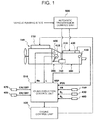
- FIG. 1 illustrates one example of an idling reduction system.
- An input shaft of a constant mesh type transmission (hereinafter, will be abbreviated as a "transmission") 300 is coupled to an output shaft of a diesel engine 100 via a friction clutch 200.
- a fuel injector 110 that injects fuel (diesel oil) into a combustion chamber is attached to a cylinder head of the diesel engine 100.
- the fuel injector 110 for example, an electronic fuel injection valve that a plunger is actuated in response to input of a drive signal and the fuel is injected through a nozzle hole in a tip can be utilized.
- a rotational speed sensor 400 that detects an engine rotational speed Ne is attached to the output shaft of the diesel engine 100.
- An output shaft of a clutch booster 210 is connected to the friction clutch 200 as one example of a clutch driving actuator.
- a stroke sensor 410 that detects a stroke L of the clutch booster 210 is attached to the friction clutch 200 in order to enable grasping of a connected/disconnected state.
- the clutch booster 210 well-known actuators such as, for example, a hydraulic cylinder that uses an oil pressure as a working fluid, an air cylinder that uses air as the working fluid and so forth can be used.
- a gearshifter 310 that switches variable speed levels is attached to the transmission 300 via, for example, a synchromesh mechanism.
- the gearshifter 310 builds therein the well-known actuator, such as, for example, the hydraulic cylinder that uses the oil pressure as the working fluid, the air cylinder that uses air as the working fluid and so forth, and executes gear shifting while taking synchronization by the synchromesh mechanism, by moving a shifting fork by this actuator.
- well-known transmissions such as, for example, a transmission that utilizes a planetary gear, a non-stage transmission and so forth can be used, not limited to the constant mesh type transmission.
- an automatic transmission control unit 500 that builds therein a microcomputer electronically controls respectively the clutch booster 210 of the friction clutch 200 and the gearshifter 310 of the transmission 300 according to a running state of a vehicle and thereby implements a so-called mechanical type automatic transmission.
- an automatic transmission control unit 500 that builds therein a microcomputer electronically controls respectively the clutch booster 210 of the friction clutch 200 and the gearshifter 310 of the transmission 300 according to a running state of a vehicle and thereby implements a so-called mechanical type automatic transmission.
- a position sensor 420 that detects a gear shift stage POS that is one example of a gear shift state, and a vehicle speed sensor 430 that detects a vehicle speed VSP from a rotational speed of an output shaft are respectively attached to the transmission 300.
- the position sensor 420 at least detects whether or not the transmission 300 is shifted to an ahead stage and whether or not the transmission 300 is shifted into neutral as the gear shift stage POS.
- Respective output signals of the rotational speed sensor 400, the stroke sensor 410, the position sensor 420 and the vehicle speed sensor 430 are input into an idling reduction control unit 510 that builds therein a microcomputer.
- respective output signals of a voltage sensor 440 that detects a battery voltage VB, a first opening sensor 450 that detects an opening ⁇ A of an accelerator pedal, and a second opening sensor 460 that detects an opening ⁇ B of a brake pedal are input into the idling reduction control unit 510.
- respective output signals of a main switch 470 that allows selection of whether or not the idling reduction system is used and a parking brake switch 480 that outputs an ON signal when a parking brake is actuated are input into the idling reduction control unit 510.
- the main switch 470 outputs an OFF signal when the idling reduction system is not used and outputs the ON signal when the idling reduction control system is used, according to an operation of a driver and others.
- the parking brake switch 480 outputs the OFF signal when the parking brake is released, that is, the parking brake is not actuated.
- the rotational speed sensor 400, the stroke sensor 410, the position sensor 420 and the vehicle speed sensor 430 are respectively given as examples of a sensor that detects the rotational speed of the engine, a sensor that detects an actuation state of the clutch, a sensor that detects the gear shifted state of the transmission and a sensor that detects the vehicle speed.
- the voltage sensor 440, the first opening sensor 450, the second opening sensor 460 and the parking brake switch 480 are respectively given as examples of a sensor that detects the voltage of a battery, a sensor that detects an operation state of the accelerator pedal, a sensor that detects the actuation state of a service brake and a sensor that detects the actuation state of the parking brake.
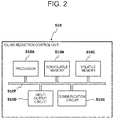
- the idling reduction control unit 510 has a processor 510A such as a CPU (Central Processing Unit) and so forth, and a nonvolatile memory 510B such as a flash ROM (Read Only Memory) and so forth, and a volatile memory 510C such as a RAM (Random Access Memory) and so forth, and an input/output circuit 510D adapted to connect together the sensors and the switches, and a communication circuit 510E that communicates with other control units.
- the processor 510A, the nonvolatile memory 510B, the volatile memory 510C, the input/output circuit 510D and the communication circuit 510E are connected via a bus 510F to be mutually communicatable.
- the automatic transmission control unit 500 and a later described engine control unit 520 are the same as the above.
- the nonvolatile memory 510B stores a control program for executing idling reduction.
- the communication circuit 510E communicates with other control units via well-known on-vehicle networks such as, for example, CAN (Controller Area Network), FlexRay (a registered trademark) and so forth.
- the idling reduction control unit 510 transmits an engine stop command to the engine control unit 520 that builds therein the microcomputer and thereby causes it to stop the diesel engine 100.
- the idling reduction control unit 510 transmits an engine restart command to the engine control unit 520 and thereby causes it to restart the diesel engine 100.
- the engine control unit 520 stops and restarts the diesel engine 100 by outputting a drive signal to, for example, the fuel injector 110 and a not illustrated starter, in response to the command from the idling reduction control unit 510.
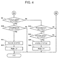
- FIG. 3 and FIG. 4 illustrate one example of an engine stopping process that the idling reduction control unit 510 repetitively executes at intervals of a predetermined time t 1 , with that the diesel engine 100 has been started by an ignition switch as a trigger.
- step 1 in the drawing, will be abbreviated as "S1". The same shall apply hereinafter), the idling reduction control unit 510 reads therein the output signal of the main switch 470 and decides whether or not the main switch 470 stays ON, in short, whether or not the idling reduction system is to be used. Then, while the idling reduction control unit 510 makes the process proceed to step 2 when it decides that the main switch 470 stays ON (Yes), it terminates the process when it decides that the main switch 470 stays OFF (No).
- the idling reduction control unit 510 reads therein the output signal of the voltage sensor 440 and decides whether or not the battery voltage VB is equal to or larger than a predetermined voltage Vth.
- the predetermined voltage Vth is a threshold value adapted for deciding whether or not the battery can afford to restart the diesel engine 100, and is appropriately set according to, for example, charging characteristics of the battery. Then, while the idling reduction control unit 510 makes the process proceed to step 3 when it decides that the battery voltage VB is equal to or larger than the predetermined voltage Vth (Yes), it terminates the process when it decides that the battery voltage VB is less than the predetermined voltage Vth (No).
- step 3 the idling reduction control unit 510 decides whether or not the idling reduction system is normal, for example, by utilizing a self-diagnosis function. Then, while the idling reduction control unit 510 makes the process proceed to step 4 when it decides that the idling reduction system is normal (Yes), it terminates the process when it decides that the idling reduction system is abnormal (No).
- the idling reduction control unit 510 reads therein the output signal of the vehicle speed sensor 430 and decides whether or not the vehicle speed VSP has been increased beyond a first predetermined value (a predetermined vehicle speed) after start of the diesel engine 100.
- a first predetermined value is a threshold value adapted for suppressing that idling reduction is executed directly after the start of the diesel engine 100 by the ignition switch, and can take a value with which it can be thought that the vehicle has started running, by taking, for example, characteristics and so forth of the vehicle speed sensor 430 into consideration.
- the idling reduction control unit 510 makes the process proceed to step 5 when it decides that the vehicle speed VSP has been increased beyond the first predetermined value (Yes), it terminates the process when it decides that the vehicle speed VSP is not increased beyond the first predetermined value (No).
- step 5 the idling reduction control unit 510 reads therein the output signal of the vehicle speed sensor 430 and decides whether or not the vehicle has stopped, via whether or not the vehicle speed VSP is equal to or smaller than a second predetermined value.
- the second predetermined value can be set to a value that enables decision of a state where it can be regarded that it has stopped such as that the vehicle is running at an extremely low speed, not limited to a state where the vehicle has completely stopped. Then, while the idling reduction control unit 510 makes the process proceed to step 6 when it decides that the vehicle has stopped (Yes), it terminates the process when it decides that the vehicle does not stop (No).
- step 6 the idling reduction control unit 510 reads therein the output signal of the first opening sensor 450 and decides whether or not the accelerator pedal is stepped on, for example, via whether or not the opening ⁇ A of the accelerator pedal is 0. Then, while the idling reduction control unit 510 makes the process proceed to step 7 when it decides that the accelerator pedal is not stepped on (Yes), it terminates the process when it decides that the accelerator pedal is stepped on (No).
- step 7 the idling reduction control unit 510 reads therein the output signal of the rotational speed sensor 400 and decides whether or not the engine rotational speed Ne is in a predetermined range.
- the predetermined range is a threshold value adapted for deciding whether or not the diesel engine 100 is stably idling and can be set as a range that it never takes, for example, in warming-up. Then, while the idling reduction control unit 510 makes the process proceeds to step 8 when it decides that the engine rotational speed Ne is within the predetermined range (Yes), it terminates the process when it decides that the engine rotational speed Ne deviates from the predetermined range (No).
- step 8 the idling reduction control unit 510 reads therein the output signal of the stroke sensor 410 and decides whether or not the friction clutch 200 is disconnected, for example, by comparing the stroke L with a third predetermined value.
- the third predetermined value can be appropriately set, for example, by taking the operating characteristics of the friction clutch 200 into consideration. Then, while the idling reduction control unit 510 makes the process proceed to step 9 when it decides that the friction clutch 200 is disconnected (Yes), it terminates the process when it decides that the friction clutch 200 is not disconnected (No). Incidentally, when the vehicle has stopped, the automatic transmission control unit 500 disconnects the friction clutch 200.
- step 9 the idling reduction control unit 510 reads therein the output signal of the second opening sensor 460 and decides whether or not the service brake is being actuated, for example, via whether or not the opening ⁇ B of the brake pedal is larger than 0. Then, while the idling reduction control unit 510 makes the process proceed to step 10 when it decides that the service brake is being actuated (Yes), it makes the process proceed to step 13 when it decides that the service brake is not being actuated (No).
- step 10 the idling reduction control unit 510 reads therein the output signal of the position sensor 420 and decides whether or not the transmission 300 is shifted to the ahead stage, via whether or not the gear shift stage POS indicates the ahead stage. Then, while the idling reduction control unit 510 makes the process proceed to step 11 when it decides that the transmission 300 is shifted to the ahead stage (Yes), it terminates the process when it decides that the transmission 300 is not shifted to the ahead stage (No).
- step 11 the idling reduction control unit 510 transmits the engine stop command to the engine control unit 520 and thereby causes it to stop the diesel engine 100.
- step 12 the idling reduction control unit 510 writes S (a halted state) into a variable Mode ensured in the volatile memory 510C in order to store the condition that has stopped the diesel engine 100.
- step 13 the idling reduction control unit 510 reads therein the output signal of the position sensor 420 and decides whether or not the transmission 300 is shifted into neutral, via whether or not the gear shift stage POS indicates the neural. Then, while the idling reduction control unit 510 makes the process proceed to step 14 when it decides that the transmission 300 is shifted into neutral (Yes), it terminates the process when it decides that the transmission 300 is not shifted into neutral (No).
- step 14 the idling reduction control unit 510 reads therein the output signal of the parking brake switch 480 and decides whether or not the parking brake is being actuated, via whether or not it is turned ON. Then, while the idling reduction control unit 510 makes the process proceed to step 15 when it decides that the parking brake is being actuated (Yes), it terminates the process when it decides that the parking brake is not being actuated (No).
- step 15 the idling reduction control unit 510 transmits the engine stop command to the engine control unit 520 and thereby causes it to stop the diesel engine 100.
- step 16 the idling reduction control unit 510 writes P (a parking state) into the variable Mode ensured in the volatile memory 510C in order to store the condition that has stopped the diesel engine 100.
- the idling reduction is executed when the battery voltage VB is equal to or larger than the predetermined voltage Vth, the idling reduction system is normal, and the vehicle speed has been increased beyond the first predetermined value from engine start. Therefore, engine stop in a state where there is a possibility that restart of the diesel engine 100 cannot be performed and engine stop immediately after engine start by the ignition switch can be avoided.
- the diesel engine 100 is automatically stopped. That is, when the service brake is actuated and the transmission 300 is shifted to the ahead stage at the time of stopping the vehicle, for example, it is decided as the "halted state” that the vehicle has temporarily stopped with the traffic signal and the diesel engine 100 is automatically stopped. In addition, when the service brake is released, the transmission 300 is shifted into neutral, and the parking brake is being actuated at the time of stopping the vehicle, for example, it is decided as the "parking state” that the vehicle stops for a long period of time and the diesel engine 100 is automatically stopped.
- the "parking state” and the "halted state” are respectively given as examples of the first condition and the second condition.
- the diesel engine 100 is automatically stopped and further fuel efficiency can be promoted in various scenes by applying the two conditions of the "halted state” and the "parking state” as the conditions under which the idling reduction is executed.
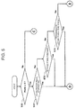
- FIG. 5 and FIG. 6 illustrate one example of an engine restarting process that the idling reduction control unit 510 repetitively executes at intervals of a predetermined time t 2 , with that the diesel engine 100 has automatically stopped by the engine stopping process as a trigger.
- the predetermined time t 2 may be the same as the predetermined time t 1 in the engine stopping process and may be different from the predetermined time t 1 (the same shall apply hereinafter).
- step 21 the idling reduction control unit 510 refers to the variable Mode of the volatile memory 510C, and decides whether or not the variable Mode is S (the halted state), in short, whether or not the diesel engine 100 has been stopped because the vehicle has entered the halted state. Then, while the idling reduction control unit 510 makes the process proceed to step 22 when it decides that the variable Mode is S (Yes), it makes the process proceed to step 25 when it decides that the variable Mode is not S (No).
- step 22 the idling reduction control unit 510 reads therein the output signal of the first opening sensor 450 and decides whether or not the accelerator pedal has been stepped on, for example, via whether or not the opening ⁇ A of the accelerator pedal is larger than 0. Then, while the idling reduction control unit 510 makes the process proceed to step 29 when it decides that the accelerator pedal has been stepped on (Yes), it makes the process proceed to step 23 when it decides that the accelerator pedal is not stepped on (No).
- step 23 the idling reduction control unit 510 reads therein the output signal of the second opening sensor 460 and decides whether or not the service brake has been released, for example, via whether or not the opening ⁇ B of the brake pedal is 0. Then, while the idling reduction control unit 510 makes the process proceed to step 29 when it decides that the service brake has been released (Yes), it makes the process proceed to step 24 when it decides that the service brake is not released (No).
- step 24 the idling reduction control unit 510 reads therein the output signal of the position sensor 420 and decides whether or not the transmission 300 has been shifted to the one other than the ahead stage, via whether the gear shift stage POS indicates neutral or an astern stage. Then, while the idling reduction control unit 510 makes the process proceed to step 29 when it decides that the transmission 300 has been shifted to the one other than the ahead stage (Yes), it terminates the process when it decides that the transmission 300 still stays at the ahead stage (No).
- step 25 the idling reduction control unit 510 reads therein the output signal of the first opening sensor 450 and decides whether or not the accelerator pedal has been stepped on, for example, via whether or not the opening ⁇ A of the accelerator pedal is larger than 0. Then, while the idling reduction control unit 510 makes the process proceed to step 29 when it decides that the accelerator pedal has been stepped on (Yes), it makes the process proceed to step 26 when it decides that the accelerator pedal is not stepped on (No).
- step 26 the idling reduction control unit 510 reads therein the output signal of the second opening sensor 460 and decides whether or not the service brake has been actuated, for example, via whether or not the opening ⁇ B of the brake pedal is larger than 0. Then, while the idling reduction control unit 510 makes the process proceed to step 29 when it decides that the service brake has been actuated (Yes), it makes the process proceed to step 27 when it decides that the service brake is not actuated (No).
- step 27 the idling reduction control unit 510 reads therein the output signal of the parking brake switch 480 and decides whether or not the parking brake has been released, via whether or not it stays OFF. Then, while the idling reduction control unit 510 makes the process proceed to step 29 when it decides that the parking brake has been released (Yes), it makes the process proceed to step 28 when it decides that the parking brake is not released (No).
- step 28 the idling reduction control unit 510 reads therein the output signal of the position sensor 420 and decides whether or not the transmission 300 has been shifted to the one other than neutral, via whether the gear shift stage POS indicates the ahead stage or the astern stage. Then, while the idling reduction control unit 510 makes the process proceed to step 29 when it decides that the transmission 300 has been shifted to the one other than neutral (Yes), it terminates the process when it decides that the transmission 300 still stays neutral (No).
- step 29 the idling reduction control unit 510 transmits the engine start command to the engine control unit 520 and thereby restarts the diesel engine 100.
- the variable Mode of the volatile memory 510C is referred to, and it is specified whether or not the diesel engine 100 has been automatically stopped in either of the "halted state” and the "parking state". Then, in a case where the diesel engine 100 has been stopped in the "halted state", when the accelerator pedal is stepped on, the service brake is released, or the transmission 300 is shifted to the one other than the ahead stage, the diesel engine 100 is restarted. On the other hand, in a case where the diesel engine 100 has been stopped in the "parking state”, when the accelerator pedal is stepped on, the service brake is actuated, the parking brake is released, or the transmission 300 is shifted to the one other than neutral, the diesel engine 100 is restarted. That is, when an operation of moving the vehicle has been executed irrespective of either the "halted state” or the "parking state", the diesel engine 100 is automatically restarted.
- FIG. 7 illustrates one example of a first mode changing process that the idling reduction control unit 510 repetitively executes at intervals of a predetermined time t 3 , with that the diesel engine 100 has automatically stopped by the engine stopping process as a trigger.
- step 31 the idling reduction control unit 510 refers to the variable Mode of the volatile memory 510C and decides whether or not the variable Mode is S (the halted state). Then, while the idling reduction control unit 510 makes the process proceed to step 32 when it decides that the variable Mode is S (Yes), it terminates the process when it decides that the variable Mode is not S (No).
- step 32 the idling reduction control unit 510 reads therein the output signal of the position sensor 420 and decides whether or not the transmission 300 has been shifted into neutral, via whether or not the gear shift stage POS indicates the neutral. Then, while the idling reduction control unit 510 makes the process proceed to step 33 when it decides that the transmission 300 has been shifted into neutral (Yes), it terminates the process when it decides that the transmission 300 is not shifted into neutral (No).
- step 33 the idling reduction control unit 510 reads therein the output signal of the second opening sensor 460 and decides whether or not the service brake has been released, for example, via whether or not the opening ⁇ B of the brake pedal has been reduced to 0. Then, while the idling reduction control unit 510 makes the process proceed to step 34 when it decides that the service brake has been released (Yes), it terminates the process when it decides that the service brake is not released (No).
- step 34 the idling reduction control unit 510 reads therein the output signal of the parking brake switch 480 and decides whether or not the parking brake has been actuated, via whether or not it has been turned ON. Then, while the idling reduction control unit 510 makes the process proceed to step 35 when it decides that the parking brake has been actuated (Yes), it terminates the process when it decides that the parking brake is not actuated (No).
- step 35 the idling reduction control unit 510 writes P (the parking state) into the variable Mode secured in the volatile memory 510C in order to change the condition under which the diesel engine 100 has been stopped from the "halted state” to the "parking state".
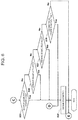
- FIG. 8 illustrates one example of a second mode changing process that the idling reduction control unit 510 repetitively executes at intervals of a predetermined time t 4 , with that the diesel engine 100 has been automatically stopped by the engine stopping process as a trigger.
- step 41 the idling reduction control unit 510 refers to the variable Mode of the volatile memory 510C and decides whether or not the variable Mode is P (the parking state). Then, while the idling reduction control unit 510 makes the process proceed to step 42 when it decides that the variable Mode is P (Yes), it terminates the process when it decides that the variable Mode is not P (No).
- step 42 the idling reduction control unit 510 reads therein the output signal of the position sensor 420 and decides whether or not the transmission 300 has been shifted to the ahead stage, via whether or not the gear shift stage POS indicates the ahead stage. Then, while the idling reduction control unit 510 makes the process proceed to step 43 when it decides that the transmission 300 has been shifted to the ahead stage (Yes), it terminates the process when it decides that the transmission 300 is not shifted to the ahead stage (No).
- step 43 the idling reduction control unit 510 reads therein the output signal of the second opening sensor 460 and decides whether or not the service brake has been actuated, for example, via whether or not the opening ⁇ B of the brake pedal is larger than 0. Then, while the idling reduction control unit 510 makes the process proceed to step 44 when it decides that the service brake has been actuated (Yes), it terminates the process when it decides that the service brake is not actuated (No).
- step 44 the idling reduction control unit 510 reads therein the output signal of the parking brake switch 480 and decides whether or not the parking brake has been released, via whether or not it stays OFF. Then, while the idling reduction control unit 510 makes the process proceed to step 45 when it decides that the parking brake has been released (Yes), it terminates the process when it decides that the parking brake is not released (No).
- step 45 the idling reduction control unit 510 writes S (the halted state) into the variable Mode secured in the volatile memory 510C, in order to change the condition under which the diesel engine 100 has been stopped from the "parking state” to the "halted state".
Landscapes
- Engineering & Computer Science (AREA)
- Chemical & Material Sciences (AREA)
- Combustion & Propulsion (AREA)
- Mechanical Engineering (AREA)
- General Engineering & Computer Science (AREA)
- Computer Hardware Design (AREA)
- Microelectronics & Electronic Packaging (AREA)
- Control Of Vehicle Engines Or Engines For Specific Uses (AREA)
- Output Control And Ontrol Of Special Type Engine (AREA)
Applications Claiming Priority (1)
| Application Number | Priority Date | Filing Date | Title |
|---|---|---|---|
| PCT/JP2013/084516 WO2015097755A1 (fr) | 2013-12-24 | 2013-12-24 | Dispositif de commande et procédé de commande pour moteurs |
Publications (3)
| Publication Number | Publication Date |
|---|---|
| EP3088710A1 true EP3088710A1 (fr) | 2016-11-02 |
| EP3088710A4 EP3088710A4 (fr) | 2017-11-15 |
| EP3088710B1 EP3088710B1 (fr) | 2020-02-12 |
Family
ID=53477698
Family Applications (1)
| Application Number | Title | Priority Date | Filing Date |
|---|---|---|---|
| EP13900548.2A Active EP3088710B1 (fr) | 2013-12-24 | 2013-12-24 | Dispositif de commande et procédé de commande pour moteurs |
Country Status (5)
| Country | Link |
|---|---|
| US (1) | US10711718B2 (fr) |
| EP (1) | EP3088710B1 (fr) |
| JP (1) | JP6363620B2 (fr) |
| CN (1) | CN105849397B (fr) |
| WO (1) | WO2015097755A1 (fr) |
Cited By (1)
| Publication number | Priority date | Publication date | Assignee | Title |
|---|---|---|---|---|
| FR3065034A1 (fr) * | 2017-04-07 | 2018-10-12 | Peugeot Citroen Automobiles Sa | Procede d'arret et de redemarrage automatique d'un moteur de vehicule |
Families Citing this family (3)
| Publication number | Priority date | Publication date | Assignee | Title |
|---|---|---|---|---|
| US9624893B2 (en) * | 2015-04-27 | 2017-04-18 | International Truck Intellectual Property Company, Llc | Engine shut-off and re-start strategy |
| CN105275631A (zh) * | 2015-10-09 | 2016-01-27 | 潍柴动力股份有限公司 | 一种发动机自动启停控制方法和装置 |
| JP6531740B2 (ja) * | 2016-08-24 | 2019-06-19 | 株式会社アドヴィックス | ブレーキ制御装置 |
Family Cites Families (27)
| Publication number | Priority date | Publication date | Assignee | Title |
|---|---|---|---|---|
| US5540299A (en) * | 1992-11-30 | 1996-07-30 | Mazda Motor Corporation | System for driving an automotive vehicle |
| JPH0942003A (ja) * | 1995-07-26 | 1997-02-10 | Hino Motors Ltd | エンジン自動停止装置 |
| DE19532135A1 (de) * | 1995-08-31 | 1997-03-06 | Clouth Gummiwerke Ag | Antriebssystem, insbesondere für ein Kraftfahrzeug, und Verfahren zum Betreiben desselben |
| JP2000314332A (ja) * | 1999-04-28 | 2000-11-14 | Toyota Motor Corp | 車両のエンジン自動停止システムの制御装置 |
| JP3758419B2 (ja) | 1999-06-11 | 2006-03-22 | 日産自動車株式会社 | アイドルストップ車両 |
| JP2001012271A (ja) * | 1999-06-29 | 2001-01-16 | Mitsubishi Motors Corp | エンジンの自動停止始動装置 |
| JP2001055941A (ja) | 1999-08-16 | 2001-02-27 | Honda Motor Co Ltd | エンジン自動始動停止制御装置 |
| JP2003120356A (ja) * | 2001-10-09 | 2003-04-23 | Toyota Motor Corp | エンジンの制御装置 |
| JP2005222417A (ja) * | 2004-02-06 | 2005-08-18 | Pioneer Electronic Corp | ポイント管理装置、車両、ポイント算出方法およびポイント算出プログラム |
| JP4524610B2 (ja) | 2004-06-28 | 2010-08-18 | マツダ株式会社 | アイドルストップ付き車両の制御装置 |
| JP2006177173A (ja) * | 2004-12-20 | 2006-07-06 | Toyota Motor Corp | 車両制御装置 |
| JP2006183600A (ja) | 2004-12-28 | 2006-07-13 | Toyota Motor Corp | エンジン停止再始動制御装置、その方法及びそれを搭載した車両 |
| JP2008128104A (ja) | 2006-11-21 | 2008-06-05 | Isuzu Motors Ltd | エンジンの自動停止始動装置 |
| US7552705B2 (en) * | 2007-03-07 | 2009-06-30 | The Gates Corporation | Vehicle stop/start system with regenerative braking |
| WO2010018900A1 (fr) | 2008-08-12 | 2010-02-18 | Min Ho Shin | Economiseur de carburant pour véhicule |
| WO2010096919A1 (fr) * | 2009-02-24 | 2010-09-02 | Gestion Andre & Paquerette Ltee | Procédé et système permettant de limiter un paramètre dynamique d'un véhicule |
| US20110112740A1 (en) * | 2009-11-11 | 2011-05-12 | Denso Corporation | Control device for internal combustion engine and method for controlling internal combustion engine |
| WO2012011533A1 (fr) * | 2010-07-23 | 2012-01-26 | 日産自動車株式会社 | Dispositif d'arrêt automatique et procédé d'arrêt automatique pour moteur à combustion interne |
| BR112013001747A2 (pt) * | 2010-07-23 | 2019-09-24 | Nissan Motor | dispositivo de interrupção automática de motor e método de interrupção automática de motor |
| JP5516883B2 (ja) * | 2010-08-24 | 2014-06-11 | マツダ株式会社 | 車両の自動停止制御装置 |
| KR20120060108A (ko) * | 2010-12-01 | 2012-06-11 | 현대자동차주식회사 | 아이에스지 시스템 및 그의 제어방법 |
| KR101199058B1 (ko) | 2010-12-06 | 2012-11-07 | 기아자동차주식회사 | Isg시스템 및 그의 제어 방법 |
| WO2012095993A1 (fr) | 2011-01-14 | 2012-07-19 | トヨタ自動車株式会社 | Appareil de commande de véhicule |
| JP5705706B2 (ja) | 2011-11-15 | 2015-04-22 | 日立建機株式会社 | 作業車両のエンジン制御装置 |
| US8690731B1 (en) * | 2012-11-30 | 2014-04-08 | Ford Global Technologies, Llc | System and method for controlling a stop-start system for a vehicle engine |
| US8936531B2 (en) * | 2013-02-21 | 2015-01-20 | Ford Global Technologies, Llc | Stop-in-park control for micro-hybrid vehicles |
| US9067595B2 (en) * | 2013-10-14 | 2015-06-30 | Ford Global Technologies, Llc | Hybrid vehicle control when towing |
-
2013
- 2013-12-24 JP JP2015554336A patent/JP6363620B2/ja not_active Expired - Fee Related
- 2013-12-24 EP EP13900548.2A patent/EP3088710B1/fr active Active
- 2013-12-24 US US15/106,197 patent/US10711718B2/en active Active
- 2013-12-24 WO PCT/JP2013/084516 patent/WO2015097755A1/fr active Application Filing
- 2013-12-24 CN CN201380081882.2A patent/CN105849397B/zh active Active
Cited By (1)
| Publication number | Priority date | Publication date | Assignee | Title |
|---|---|---|---|---|
| FR3065034A1 (fr) * | 2017-04-07 | 2018-10-12 | Peugeot Citroen Automobiles Sa | Procede d'arret et de redemarrage automatique d'un moteur de vehicule |
Also Published As
| Publication number | Publication date |
|---|---|
| EP3088710A4 (fr) | 2017-11-15 |
| US20160369725A1 (en) | 2016-12-22 |
| CN105849397A (zh) | 2016-08-10 |
| CN105849397B (zh) | 2019-06-18 |
| EP3088710B1 (fr) | 2020-02-12 |
| WO2015097755A1 (fr) | 2015-07-02 |
| US10711718B2 (en) | 2020-07-14 |
| JPWO2015097755A1 (ja) | 2017-03-23 |
| JP6363620B2 (ja) | 2018-07-25 |
Similar Documents
| Publication | Publication Date | Title |
|---|---|---|
| JP5323748B2 (ja) | 自動変速機の油圧制御装置 | |
| EP3179125B1 (fr) | Dispositif et procédé de commande de véhicule | |
| US10036340B2 (en) | Controller for vehicle and control method for vehicle | |
| US9598059B2 (en) | Control apparatus for vehicle | |
| CN104648373A (zh) | 用于停止/起动发动机的方法和系统 | |
| CN107264509B (zh) | 用于控制车辆发动机的启动-停止系统的系统和方法 | |
| EP3088710B1 (fr) | Dispositif de commande et procédé de commande pour moteurs | |
| US9567963B2 (en) | Vehicle control device | |
| JP5620948B2 (ja) | 車両の制御装置 | |
| CN103328791B (zh) | 发动机再启动控制装置、车辆以及车辆控制方法 | |
| US9657703B2 (en) | Internal combustion engine starting device | |
| US8608620B2 (en) | Control method of assist pump for automatic transmission of vehicle provided with ISG system | |
| JP6394312B2 (ja) | 内燃機関のアイドリングストップの制御システム | |
| JP6007816B2 (ja) | 車両の制御装置 | |
| CN107683367B (zh) | 车载控制装置 | |
| RU2735193C2 (ru) | Способ управления мотором транспортного средства и устройство управления двигателем и мотором транспортного средства | |
| KR100851239B1 (ko) | 디젤자동차에서 변속기 프릭션 저감장치 및 그 방법 | |
| JP2010116972A (ja) | クラッチ制御装置およびクラッチ制御方法 | |
| JP2016098691A (ja) | 内燃機関の制御システム | |
| JP2015078655A (ja) | 車両制御装置 |
Legal Events
| Date | Code | Title | Description |
|---|---|---|---|
| PUAI | Public reference made under article 153(3) epc to a published international application that has entered the european phase |
Free format text: ORIGINAL CODE: 0009012 |
|
| 17P | Request for examination filed |
Effective date: 20160720 |
|
| AK | Designated contracting states |
Kind code of ref document: A1 Designated state(s): AL AT BE BG CH CY CZ DE DK EE ES FI FR GB GR HR HU IE IS IT LI LT LU LV MC MK MT NL NO PL PT RO RS SE SI SK SM TR |
|
| AX | Request for extension of the european patent |
Extension state: BA ME |
|
| DAX | Request for extension of the european patent (deleted) | ||
| A4 | Supplementary search report drawn up and despatched |
Effective date: 20171013 |
|
| RIC1 | Information provided on ipc code assigned before grant |
Ipc: F02D 17/00 20060101ALI20171009BHEP Ipc: F02D 29/02 20060101AFI20171009BHEP |
|
| STAA | Information on the status of an ep patent application or granted ep patent |
Free format text: STATUS: EXAMINATION IS IN PROGRESS |
|
| 17Q | First examination report despatched |
Effective date: 20190128 |
|
| GRAP | Despatch of communication of intention to grant a patent |
Free format text: ORIGINAL CODE: EPIDOSNIGR1 |
|
| STAA | Information on the status of an ep patent application or granted ep patent |
Free format text: STATUS: GRANT OF PATENT IS INTENDED |
|
| INTG | Intention to grant announced |
Effective date: 20191016 |
|
| GRAS | Grant fee paid |
Free format text: ORIGINAL CODE: EPIDOSNIGR3 |
|
| GRAA | (expected) grant |
Free format text: ORIGINAL CODE: 0009210 |
|
| STAA | Information on the status of an ep patent application or granted ep patent |
Free format text: STATUS: THE PATENT HAS BEEN GRANTED |
|
| AK | Designated contracting states |
Kind code of ref document: B1 Designated state(s): AL AT BE BG CH CY CZ DE DK EE ES FI FR GB GR HR HU IE IS IT LI LT LU LV MC MK MT NL NO PL PT RO RS SE SI SK SM TR |
|
| REG | Reference to a national code |
Ref country code: GB Ref legal event code: FG4D |
|
| REG | Reference to a national code |
Ref country code: CH Ref legal event code: EP |
|
| REG | Reference to a national code |
Ref country code: AT Ref legal event code: REF Ref document number: 1232413 Country of ref document: AT Kind code of ref document: T Effective date: 20200215 |
|
| REG | Reference to a national code |
Ref country code: IE Ref legal event code: FG4D |
|
| REG | Reference to a national code |
Ref country code: DE Ref legal event code: R096 Ref document number: 602013065864 Country of ref document: DE |
|
| PG25 | Lapsed in a contracting state [announced via postgrant information from national office to epo] |
Ref country code: NO Free format text: LAPSE BECAUSE OF FAILURE TO SUBMIT A TRANSLATION OF THE DESCRIPTION OR TO PAY THE FEE WITHIN THE PRESCRIBED TIME-LIMIT Effective date: 20200512 Ref country code: FI Free format text: LAPSE BECAUSE OF FAILURE TO SUBMIT A TRANSLATION OF THE DESCRIPTION OR TO PAY THE FEE WITHIN THE PRESCRIBED TIME-LIMIT Effective date: 20200212 Ref country code: RS Free format text: LAPSE BECAUSE OF FAILURE TO SUBMIT A TRANSLATION OF THE DESCRIPTION OR TO PAY THE FEE WITHIN THE PRESCRIBED TIME-LIMIT Effective date: 20200212 |
|
| REG | Reference to a national code |
Ref country code: LT Ref legal event code: MG4D |
|
| REG | Reference to a national code |
Ref country code: NL Ref legal event code: MP Effective date: 20200212 |
|
| PG25 | Lapsed in a contracting state [announced via postgrant information from national office to epo] |
Ref country code: GR Free format text: LAPSE BECAUSE OF FAILURE TO SUBMIT A TRANSLATION OF THE DESCRIPTION OR TO PAY THE FEE WITHIN THE PRESCRIBED TIME-LIMIT Effective date: 20200513 Ref country code: LV Free format text: LAPSE BECAUSE OF FAILURE TO SUBMIT A TRANSLATION OF THE DESCRIPTION OR TO PAY THE FEE WITHIN THE PRESCRIBED TIME-LIMIT Effective date: 20200212 Ref country code: HR Free format text: LAPSE BECAUSE OF FAILURE TO SUBMIT A TRANSLATION OF THE DESCRIPTION OR TO PAY THE FEE WITHIN THE PRESCRIBED TIME-LIMIT Effective date: 20200212 Ref country code: SE Free format text: LAPSE BECAUSE OF FAILURE TO SUBMIT A TRANSLATION OF THE DESCRIPTION OR TO PAY THE FEE WITHIN THE PRESCRIBED TIME-LIMIT Effective date: 20200212 Ref country code: BG Free format text: LAPSE BECAUSE OF FAILURE TO SUBMIT A TRANSLATION OF THE DESCRIPTION OR TO PAY THE FEE WITHIN THE PRESCRIBED TIME-LIMIT Effective date: 20200512 Ref country code: IS Free format text: LAPSE BECAUSE OF FAILURE TO SUBMIT A TRANSLATION OF THE DESCRIPTION OR TO PAY THE FEE WITHIN THE PRESCRIBED TIME-LIMIT Effective date: 20200612 |
|
| PG25 | Lapsed in a contracting state [announced via postgrant information from national office to epo] |
Ref country code: NL Free format text: LAPSE BECAUSE OF FAILURE TO SUBMIT A TRANSLATION OF THE DESCRIPTION OR TO PAY THE FEE WITHIN THE PRESCRIBED TIME-LIMIT Effective date: 20200212 |
|
| PG25 | Lapsed in a contracting state [announced via postgrant information from national office to epo] |
Ref country code: LT Free format text: LAPSE BECAUSE OF FAILURE TO SUBMIT A TRANSLATION OF THE DESCRIPTION OR TO PAY THE FEE WITHIN THE PRESCRIBED TIME-LIMIT Effective date: 20200212 Ref country code: ES Free format text: LAPSE BECAUSE OF FAILURE TO SUBMIT A TRANSLATION OF THE DESCRIPTION OR TO PAY THE FEE WITHIN THE PRESCRIBED TIME-LIMIT Effective date: 20200212 Ref country code: SK Free format text: LAPSE BECAUSE OF FAILURE TO SUBMIT A TRANSLATION OF THE DESCRIPTION OR TO PAY THE FEE WITHIN THE PRESCRIBED TIME-LIMIT Effective date: 20200212 Ref country code: CZ Free format text: LAPSE BECAUSE OF FAILURE TO SUBMIT A TRANSLATION OF THE DESCRIPTION OR TO PAY THE FEE WITHIN THE PRESCRIBED TIME-LIMIT Effective date: 20200212 Ref country code: RO Free format text: LAPSE BECAUSE OF FAILURE TO SUBMIT A TRANSLATION OF THE DESCRIPTION OR TO PAY THE FEE WITHIN THE PRESCRIBED TIME-LIMIT Effective date: 20200212 Ref country code: DK Free format text: LAPSE BECAUSE OF FAILURE TO SUBMIT A TRANSLATION OF THE DESCRIPTION OR TO PAY THE FEE WITHIN THE PRESCRIBED TIME-LIMIT Effective date: 20200212 Ref country code: EE Free format text: LAPSE BECAUSE OF FAILURE TO SUBMIT A TRANSLATION OF THE DESCRIPTION OR TO PAY THE FEE WITHIN THE PRESCRIBED TIME-LIMIT Effective date: 20200212 Ref country code: SM Free format text: LAPSE BECAUSE OF FAILURE TO SUBMIT A TRANSLATION OF THE DESCRIPTION OR TO PAY THE FEE WITHIN THE PRESCRIBED TIME-LIMIT Effective date: 20200212 Ref country code: PT Free format text: LAPSE BECAUSE OF FAILURE TO SUBMIT A TRANSLATION OF THE DESCRIPTION OR TO PAY THE FEE WITHIN THE PRESCRIBED TIME-LIMIT Effective date: 20200705 |
|
| REG | Reference to a national code |
Ref country code: DE Ref legal event code: R097 Ref document number: 602013065864 Country of ref document: DE |
|
| REG | Reference to a national code |
Ref country code: AT Ref legal event code: MK05 Ref document number: 1232413 Country of ref document: AT Kind code of ref document: T Effective date: 20200212 |
|
| PLBE | No opposition filed within time limit |
Free format text: ORIGINAL CODE: 0009261 |
|
| STAA | Information on the status of an ep patent application or granted ep patent |
Free format text: STATUS: NO OPPOSITION FILED WITHIN TIME LIMIT |
|
| 26N | No opposition filed |
Effective date: 20201113 |
|
| PG25 | Lapsed in a contracting state [announced via postgrant information from national office to epo] |
Ref country code: AT Free format text: LAPSE BECAUSE OF FAILURE TO SUBMIT A TRANSLATION OF THE DESCRIPTION OR TO PAY THE FEE WITHIN THE PRESCRIBED TIME-LIMIT Effective date: 20200212 Ref country code: IT Free format text: LAPSE BECAUSE OF FAILURE TO SUBMIT A TRANSLATION OF THE DESCRIPTION OR TO PAY THE FEE WITHIN THE PRESCRIBED TIME-LIMIT Effective date: 20200212 |
|
| PG25 | Lapsed in a contracting state [announced via postgrant information from national office to epo] |
Ref country code: PL Free format text: LAPSE BECAUSE OF FAILURE TO SUBMIT A TRANSLATION OF THE DESCRIPTION OR TO PAY THE FEE WITHIN THE PRESCRIBED TIME-LIMIT Effective date: 20200212 Ref country code: SI Free format text: LAPSE BECAUSE OF FAILURE TO SUBMIT A TRANSLATION OF THE DESCRIPTION OR TO PAY THE FEE WITHIN THE PRESCRIBED TIME-LIMIT Effective date: 20200212 |
|
| REG | Reference to a national code |
Ref country code: CH Ref legal event code: PL |
|
| GBPC | Gb: european patent ceased through non-payment of renewal fee |
Effective date: 20201224 |
|
| PG25 | Lapsed in a contracting state [announced via postgrant information from national office to epo] |
Ref country code: MC Free format text: LAPSE BECAUSE OF FAILURE TO SUBMIT A TRANSLATION OF THE DESCRIPTION OR TO PAY THE FEE WITHIN THE PRESCRIBED TIME-LIMIT Effective date: 20200212 |
|
| REG | Reference to a national code |
Ref country code: BE Ref legal event code: MM Effective date: 20201231 |
|
| PG25 | Lapsed in a contracting state [announced via postgrant information from national office to epo] |
Ref country code: LU Free format text: LAPSE BECAUSE OF NON-PAYMENT OF DUE FEES Effective date: 20201224 Ref country code: IE Free format text: LAPSE BECAUSE OF NON-PAYMENT OF DUE FEES Effective date: 20201224 |
|
| PG25 | Lapsed in a contracting state [announced via postgrant information from national office to epo] |
Ref country code: CH Free format text: LAPSE BECAUSE OF NON-PAYMENT OF DUE FEES Effective date: 20201231 Ref country code: GB Free format text: LAPSE BECAUSE OF NON-PAYMENT OF DUE FEES Effective date: 20201224 Ref country code: LI Free format text: LAPSE BECAUSE OF NON-PAYMENT OF DUE FEES Effective date: 20201231 |
|
| PG25 | Lapsed in a contracting state [announced via postgrant information from national office to epo] |
Ref country code: TR Free format text: LAPSE BECAUSE OF FAILURE TO SUBMIT A TRANSLATION OF THE DESCRIPTION OR TO PAY THE FEE WITHIN THE PRESCRIBED TIME-LIMIT Effective date: 20200212 Ref country code: MT Free format text: LAPSE BECAUSE OF FAILURE TO SUBMIT A TRANSLATION OF THE DESCRIPTION OR TO PAY THE FEE WITHIN THE PRESCRIBED TIME-LIMIT Effective date: 20200212 Ref country code: CY Free format text: LAPSE BECAUSE OF FAILURE TO SUBMIT A TRANSLATION OF THE DESCRIPTION OR TO PAY THE FEE WITHIN THE PRESCRIBED TIME-LIMIT Effective date: 20200212 |
|
| PG25 | Lapsed in a contracting state [announced via postgrant information from national office to epo] |
Ref country code: MK Free format text: LAPSE BECAUSE OF FAILURE TO SUBMIT A TRANSLATION OF THE DESCRIPTION OR TO PAY THE FEE WITHIN THE PRESCRIBED TIME-LIMIT Effective date: 20200212 Ref country code: AL Free format text: LAPSE BECAUSE OF FAILURE TO SUBMIT A TRANSLATION OF THE DESCRIPTION OR TO PAY THE FEE WITHIN THE PRESCRIBED TIME-LIMIT Effective date: 20200212 |
|
| PG25 | Lapsed in a contracting state [announced via postgrant information from national office to epo] |
Ref country code: BE Free format text: LAPSE BECAUSE OF NON-PAYMENT OF DUE FEES Effective date: 20201231 |
|
| PGFP | Annual fee paid to national office [announced via postgrant information from national office to epo] |
Ref country code: FR Payment date: 20221222 Year of fee payment: 10 |
|
| PGFP | Annual fee paid to national office [announced via postgrant information from national office to epo] |
Ref country code: DE Payment date: 20231227 Year of fee payment: 11 |