EP3065205B1 - Electrode and cell having electrode - Google Patents
Electrode and cell having electrode Download PDFInfo
- Publication number
- EP3065205B1 EP3065205B1 EP14857195.3A EP14857195A EP3065205B1 EP 3065205 B1 EP3065205 B1 EP 3065205B1 EP 14857195 A EP14857195 A EP 14857195A EP 3065205 B1 EP3065205 B1 EP 3065205B1
- Authority
- EP
- European Patent Office
- Prior art keywords
- active material
- material layer
- insulating member
- electrode
- positive electrode
- Prior art date
- Legal status (The legal status is an assumption and is not a legal conclusion. Google has not performed a legal analysis and makes no representation as to the accuracy of the status listed.)
- Active
Links
- 239000011149 active material Substances 0.000 claims description 151
- 230000007423 decrease Effects 0.000 claims description 7
- 238000010248 power generation Methods 0.000 description 41
- 239000008151 electrolyte solution Substances 0.000 description 23
- 239000000463 material Substances 0.000 description 22
- -1 polyethylene Polymers 0.000 description 19
- 230000002093 peripheral effect Effects 0.000 description 15
- 239000011230 binding agent Substances 0.000 description 12
- 230000014759 maintenance of location Effects 0.000 description 11
- 238000012360 testing method Methods 0.000 description 11
- 239000004743 Polypropylene Substances 0.000 description 9
- 230000000052 comparative effect Effects 0.000 description 9
- 238000003411 electrode reaction Methods 0.000 description 9
- 229920001155 polypropylene Polymers 0.000 description 9
- 229920002981 polyvinylidene fluoride Polymers 0.000 description 9
- 238000000034 method Methods 0.000 description 8
- 239000004698 Polyethylene Substances 0.000 description 7
- 229910052782 aluminium Inorganic materials 0.000 description 7
- XAGFODPZIPBFFR-UHFFFAOYSA-N aluminium Chemical compound [Al] XAGFODPZIPBFFR-UHFFFAOYSA-N 0.000 description 7
- 239000011255 nonaqueous electrolyte Substances 0.000 description 7
- 229920000573 polyethylene Polymers 0.000 description 7
- 239000002033 PVDF binder Substances 0.000 description 6
- 239000000853 adhesive Substances 0.000 description 6
- 230000001070 adhesive effect Effects 0.000 description 6
- 229920000642 polymer Polymers 0.000 description 6
- RYGMFSIKBFXOCR-UHFFFAOYSA-N Copper Chemical compound [Cu] RYGMFSIKBFXOCR-UHFFFAOYSA-N 0.000 description 5
- 239000004952 Polyamide Substances 0.000 description 5
- 238000006243 chemical reaction Methods 0.000 description 5
- 229920001577 copolymer Polymers 0.000 description 5
- 238000006073 displacement reaction Methods 0.000 description 5
- 239000011267 electrode slurry Substances 0.000 description 5
- 239000003792 electrolyte Substances 0.000 description 5
- 229920002647 polyamide Polymers 0.000 description 5
- 239000000758 substrate Substances 0.000 description 5
- 239000011800 void material Substances 0.000 description 5
- KMTRUDSVKNLOMY-UHFFFAOYSA-N Ethylene carbonate Chemical compound O=C1OCCO1 KMTRUDSVKNLOMY-UHFFFAOYSA-N 0.000 description 4
- SECXISVLQFMRJM-UHFFFAOYSA-N N-Methylpyrrolidone Chemical compound CN1CCCC1=O SECXISVLQFMRJM-UHFFFAOYSA-N 0.000 description 4
- PXHVJJICTQNCMI-UHFFFAOYSA-N Nickel Chemical compound [Ni] PXHVJJICTQNCMI-UHFFFAOYSA-N 0.000 description 4
- 239000004642 Polyimide Substances 0.000 description 4
- 229920002239 polyacrylonitrile Polymers 0.000 description 4
- 229920000139 polyethylene terephthalate Polymers 0.000 description 4
- 239000005020 polyethylene terephthalate Substances 0.000 description 4
- 229920001721 polyimide Polymers 0.000 description 4
- OKTJSMMVPCPJKN-UHFFFAOYSA-N Carbon Chemical compound [C] OKTJSMMVPCPJKN-UHFFFAOYSA-N 0.000 description 3
- YCKRFDGAMUMZLT-UHFFFAOYSA-N Fluorine atom Chemical compound [F] YCKRFDGAMUMZLT-UHFFFAOYSA-N 0.000 description 3
- 229910001290 LiPF6 Inorganic materials 0.000 description 3
- HBBGRARXTFLTSG-UHFFFAOYSA-N Lithium ion Chemical compound [Li+] HBBGRARXTFLTSG-UHFFFAOYSA-N 0.000 description 3
- 239000002390 adhesive tape Substances 0.000 description 3
- 239000010949 copper Substances 0.000 description 3
- 229910052802 copper Inorganic materials 0.000 description 3
- 229920001971 elastomer Polymers 0.000 description 3
- 239000011737 fluorine Substances 0.000 description 3
- 229910052731 fluorine Inorganic materials 0.000 description 3
- 239000011888 foil Substances 0.000 description 3
- HCDGVLDPFQMKDK-UHFFFAOYSA-N hexafluoropropylene Chemical group FC(F)=C(F)C(F)(F)F HCDGVLDPFQMKDK-UHFFFAOYSA-N 0.000 description 3
- 229910001416 lithium ion Inorganic materials 0.000 description 3
- 229910052751 metal Inorganic materials 0.000 description 3
- 239000002184 metal Substances 0.000 description 3
- 239000003960 organic solvent Substances 0.000 description 3
- 229920003229 poly(methyl methacrylate) Polymers 0.000 description 3
- 239000004926 polymethyl methacrylate Substances 0.000 description 3
- 239000004810 polytetrafluoroethylene Substances 0.000 description 3
- 229920001343 polytetrafluoroethylene Polymers 0.000 description 3
- RUOJZAUFBMNUDX-UHFFFAOYSA-N propylene carbonate Chemical compound CC1COC(=O)O1 RUOJZAUFBMNUDX-UHFFFAOYSA-N 0.000 description 3
- 229920005989 resin Polymers 0.000 description 3
- 239000011347 resin Substances 0.000 description 3
- 239000005060 rubber Substances 0.000 description 3
- 229920003048 styrene butadiene rubber Polymers 0.000 description 3
- 229920002134 Carboxymethyl cellulose Polymers 0.000 description 2
- XEEYBQQBJWHFJM-UHFFFAOYSA-N Iron Chemical compound [Fe] XEEYBQQBJWHFJM-UHFFFAOYSA-N 0.000 description 2
- 229920000106 Liquid crystal polymer Polymers 0.000 description 2
- 239000004977 Liquid-crystal polymers (LCPs) Substances 0.000 description 2
- 229920003171 Poly (ethylene oxide) Polymers 0.000 description 2
- 239000004696 Poly ether ether ketone Substances 0.000 description 2
- 239000004734 Polyphenylene sulfide Substances 0.000 description 2
- WYURNTSHIVDZCO-UHFFFAOYSA-N Tetrahydrofuran Chemical compound C1CCOC1 WYURNTSHIVDZCO-UHFFFAOYSA-N 0.000 description 2
- 229920000122 acrylonitrile butadiene styrene Polymers 0.000 description 2
- 229910052799 carbon Inorganic materials 0.000 description 2
- 239000001768 carboxy methyl cellulose Substances 0.000 description 2
- 235000010948 carboxy methyl cellulose Nutrition 0.000 description 2
- 239000008112 carboxymethyl-cellulose Substances 0.000 description 2
- 238000000576 coating method Methods 0.000 description 2
- 150000002500 ions Chemical class 0.000 description 2
- 229910003002 lithium salt Inorganic materials 0.000 description 2
- 159000000002 lithium salts Chemical class 0.000 description 2
- 229910021437 lithium-transition metal oxide Inorganic materials 0.000 description 2
- 238000004519 manufacturing process Methods 0.000 description 2
- 239000007773 negative electrode material Substances 0.000 description 2
- 229910052759 nickel Inorganic materials 0.000 description 2
- 239000004745 nonwoven fabric Substances 0.000 description 2
- 229920002492 poly(sulfone) Polymers 0.000 description 2
- 229920001230 polyarylate Polymers 0.000 description 2
- 229920001707 polybutylene terephthalate Polymers 0.000 description 2
- 229920002530 polyetherether ketone Polymers 0.000 description 2
- 229920006324 polyoxymethylene Polymers 0.000 description 2
- 229920001955 polyphenylene ether Polymers 0.000 description 2
- 229920000069 polyphenylene sulfide Polymers 0.000 description 2
- 229920001451 polypropylene glycol Polymers 0.000 description 2
- 239000011118 polyvinyl acetate Substances 0.000 description 2
- 229920002689 polyvinyl acetate Polymers 0.000 description 2
- 239000004800 polyvinyl chloride Substances 0.000 description 2
- 239000000843 powder Substances 0.000 description 2
- 239000002904 solvent Substances 0.000 description 2
- 239000000126 substance Substances 0.000 description 2
- BQCIDUSAKPWEOX-UHFFFAOYSA-N 1,1-Difluoroethene Chemical compound FC(F)=C BQCIDUSAKPWEOX-UHFFFAOYSA-N 0.000 description 1
- OQMIRQSWHKCKNJ-UHFFFAOYSA-N 1,1-difluoroethene;1,1,2,3,3,3-hexafluoroprop-1-ene Chemical group FC(F)=C.FC(F)=C(F)C(F)(F)F OQMIRQSWHKCKNJ-UHFFFAOYSA-N 0.000 description 1
- QTBSBXVTEAMEQO-UHFFFAOYSA-M Acetate Chemical compound CC([O-])=O QTBSBXVTEAMEQO-UHFFFAOYSA-M 0.000 description 1
- 239000004925 Acrylic resin Substances 0.000 description 1
- 229920000178 Acrylic resin Polymers 0.000 description 1
- 229920000742 Cotton Polymers 0.000 description 1
- 229920000181 Ethylene propylene rubber Polymers 0.000 description 1
- 229910000552 LiCF3SO3 Inorganic materials 0.000 description 1
- 229910002097 Lithium manganese(III,IV) oxide Inorganic materials 0.000 description 1
- 239000004677 Nylon Substances 0.000 description 1
- 229920012266 Poly(ether sulfone) PES Polymers 0.000 description 1
- 229930182556 Polyacetal Natural products 0.000 description 1
- 239000005062 Polybutadiene Substances 0.000 description 1
- 239000004793 Polystyrene Substances 0.000 description 1
- 229920000297 Rayon Polymers 0.000 description 1
- 239000002174 Styrene-butadiene Substances 0.000 description 1
- RTAQQCXQSZGOHL-UHFFFAOYSA-N Titanium Chemical compound [Ti] RTAQQCXQSZGOHL-UHFFFAOYSA-N 0.000 description 1
- XECAHXYUAAWDEL-UHFFFAOYSA-N acrylonitrile butadiene styrene Chemical compound C=CC=C.C=CC#N.C=CC1=CC=CC=C1 XECAHXYUAAWDEL-UHFFFAOYSA-N 0.000 description 1
- 239000004676 acrylonitrile butadiene styrene Substances 0.000 description 1
- 229920001893 acrylonitrile styrene Polymers 0.000 description 1
- 239000004760 aramid Substances 0.000 description 1
- 229920003235 aromatic polyamide Polymers 0.000 description 1
- 230000015572 biosynthetic process Effects 0.000 description 1
- 230000009172 bursting Effects 0.000 description 1
- 239000003990 capacitor Substances 0.000 description 1
- 239000003575 carbonaceous material Substances 0.000 description 1
- 229920002678 cellulose Polymers 0.000 description 1
- 239000001913 cellulose Substances 0.000 description 1
- 150000005678 chain carbonates Chemical class 0.000 description 1
- 239000011248 coating agent Substances 0.000 description 1
- 239000002131 composite material Substances 0.000 description 1
- 238000010281 constant-current constant-voltage charging Methods 0.000 description 1
- 150000005676 cyclic carbonates Chemical class 0.000 description 1
- 125000004122 cyclic group Chemical group 0.000 description 1
- IEJIGPNLZYLLBP-UHFFFAOYSA-N dimethyl carbonate Chemical compound COC(=O)OC IEJIGPNLZYLLBP-UHFFFAOYSA-N 0.000 description 1
- 238000001035 drying Methods 0.000 description 1
- 238000005516 engineering process Methods 0.000 description 1
- 239000003822 epoxy resin Substances 0.000 description 1
- 150000002170 ethers Chemical class 0.000 description 1
- 239000005038 ethylene vinyl acetate Substances 0.000 description 1
- 239000000446 fuel Substances 0.000 description 1
- 229910002804 graphite Inorganic materials 0.000 description 1
- 239000010439 graphite Substances 0.000 description 1
- 229910021385 hard carbon Inorganic materials 0.000 description 1
- 229910052742 iron Inorganic materials 0.000 description 1
- 229920003049 isoprene rubber Polymers 0.000 description 1
- URIIGZKXFBNRAU-UHFFFAOYSA-N lithium;oxonickel Chemical compound [Li].[Ni]=O URIIGZKXFBNRAU-UHFFFAOYSA-N 0.000 description 1
- 230000007774 longterm Effects 0.000 description 1
- 239000002905 metal composite material Substances 0.000 description 1
- 150000002739 metals Chemical class 0.000 description 1
- 238000012986 modification Methods 0.000 description 1
- 230000004048 modification Effects 0.000 description 1
- 229910021470 non-graphitizable carbon Inorganic materials 0.000 description 1
- 229920001778 nylon Polymers 0.000 description 1
- 238000007747 plating Methods 0.000 description 1
- 229920001200 poly(ethylene-vinyl acetate) Polymers 0.000 description 1
- 229920005569 poly(vinylidene fluoride-co-hexafluoropropylene) Polymers 0.000 description 1
- 229920002312 polyamide-imide Polymers 0.000 description 1
- 229920002857 polybutadiene Polymers 0.000 description 1
- 239000004417 polycarbonate Substances 0.000 description 1
- 229920000515 polycarbonate Polymers 0.000 description 1
- 229920000647 polyepoxide Polymers 0.000 description 1
- 229920000728 polyester Polymers 0.000 description 1
- 239000005518 polymer electrolyte Substances 0.000 description 1
- 229920000098 polyolefin Polymers 0.000 description 1
- 229920000346 polystyrene-polyisoprene block-polystyrene Polymers 0.000 description 1
- 229920000915 polyvinyl chloride Polymers 0.000 description 1
- 229920002620 polyvinyl fluoride Polymers 0.000 description 1
- 239000007774 positive electrode material Substances 0.000 description 1
- SCUZVMOVTVSBLE-UHFFFAOYSA-N prop-2-enenitrile;styrene Chemical compound C=CC#N.C=CC1=CC=CC=C1 SCUZVMOVTVSBLE-UHFFFAOYSA-N 0.000 description 1
- 239000002964 rayon Substances 0.000 description 1
- 230000009257 reactivity Effects 0.000 description 1
- 230000009467 reduction Effects 0.000 description 1
- 150000003839 salts Chemical class 0.000 description 1
- 239000002002 slurry Substances 0.000 description 1
- 239000007787 solid Substances 0.000 description 1
- 229910001220 stainless steel Inorganic materials 0.000 description 1
- 239000010935 stainless steel Substances 0.000 description 1
- 229920000468 styrene butadiene styrene block copolymer Polymers 0.000 description 1
- YLQBMQCUIZJEEH-UHFFFAOYSA-N tetrahydrofuran Natural products C=1C=COC=1 YLQBMQCUIZJEEH-UHFFFAOYSA-N 0.000 description 1
- 229920001169 thermoplastic Polymers 0.000 description 1
- 229920006259 thermoplastic polyimide Polymers 0.000 description 1
- 229920005992 thermoplastic resin Polymers 0.000 description 1
- 239000010936 titanium Substances 0.000 description 1
- 229910052719 titanium Inorganic materials 0.000 description 1
- 229910052723 transition metal Inorganic materials 0.000 description 1
- XLYOFNOQVPJJNP-UHFFFAOYSA-N water Substances O XLYOFNOQVPJJNP-UHFFFAOYSA-N 0.000 description 1
Images


Classifications
-
- H—ELECTRICITY
- H01—ELECTRIC ELEMENTS
- H01M—PROCESSES OR MEANS, e.g. BATTERIES, FOR THE DIRECT CONVERSION OF CHEMICAL ENERGY INTO ELECTRICAL ENERGY
- H01M4/00—Electrodes
- H01M4/02—Electrodes composed of, or comprising, active material
- H01M4/62—Selection of inactive substances as ingredients for active masses, e.g. binders, fillers
- H01M4/628—Inhibitors, e.g. gassing inhibitors, corrosion inhibitors
-
- H—ELECTRICITY
- H01—ELECTRIC ELEMENTS
- H01M—PROCESSES OR MEANS, e.g. BATTERIES, FOR THE DIRECT CONVERSION OF CHEMICAL ENERGY INTO ELECTRICAL ENERGY
- H01M4/00—Electrodes
- H01M4/02—Electrodes composed of, or comprising, active material
- H01M4/13—Electrodes for accumulators with non-aqueous electrolyte, e.g. for lithium-accumulators; Processes of manufacture thereof
-
- H—ELECTRICITY
- H01—ELECTRIC ELEMENTS
- H01M—PROCESSES OR MEANS, e.g. BATTERIES, FOR THE DIRECT CONVERSION OF CHEMICAL ENERGY INTO ELECTRICAL ENERGY
- H01M10/00—Secondary cells; Manufacture thereof
- H01M10/05—Accumulators with non-aqueous electrolyte
- H01M10/052—Li-accumulators
- H01M10/0525—Rocking-chair batteries, i.e. batteries with lithium insertion or intercalation in both electrodes; Lithium-ion batteries
-
- H—ELECTRICITY
- H01—ELECTRIC ELEMENTS
- H01M—PROCESSES OR MEANS, e.g. BATTERIES, FOR THE DIRECT CONVERSION OF CHEMICAL ENERGY INTO ELECTRICAL ENERGY
- H01M10/00—Secondary cells; Manufacture thereof
- H01M10/05—Accumulators with non-aqueous electrolyte
- H01M10/056—Accumulators with non-aqueous electrolyte characterised by the materials used as electrolytes, e.g. mixed inorganic/organic electrolytes
- H01M10/0564—Accumulators with non-aqueous electrolyte characterised by the materials used as electrolytes, e.g. mixed inorganic/organic electrolytes the electrolyte being constituted of organic materials only
- H01M10/0566—Liquid materials
- H01M10/0568—Liquid materials characterised by the solutes
-
- H—ELECTRICITY
- H01—ELECTRIC ELEMENTS
- H01M—PROCESSES OR MEANS, e.g. BATTERIES, FOR THE DIRECT CONVERSION OF CHEMICAL ENERGY INTO ELECTRICAL ENERGY
- H01M10/00—Secondary cells; Manufacture thereof
- H01M10/05—Accumulators with non-aqueous electrolyte
- H01M10/056—Accumulators with non-aqueous electrolyte characterised by the materials used as electrolytes, e.g. mixed inorganic/organic electrolytes
- H01M10/0564—Accumulators with non-aqueous electrolyte characterised by the materials used as electrolytes, e.g. mixed inorganic/organic electrolytes the electrolyte being constituted of organic materials only
- H01M10/0566—Liquid materials
- H01M10/0569—Liquid materials characterised by the solvents
-
- H—ELECTRICITY
- H01—ELECTRIC ELEMENTS
- H01M—PROCESSES OR MEANS, e.g. BATTERIES, FOR THE DIRECT CONVERSION OF CHEMICAL ENERGY INTO ELECTRICAL ENERGY
- H01M10/00—Secondary cells; Manufacture thereof
- H01M10/05—Accumulators with non-aqueous electrolyte
- H01M10/058—Construction or manufacture
- H01M10/0585—Construction or manufacture of accumulators having only flat construction elements, i.e. flat positive electrodes, flat negative electrodes and flat separators
-
- H—ELECTRICITY
- H01—ELECTRIC ELEMENTS
- H01M—PROCESSES OR MEANS, e.g. BATTERIES, FOR THE DIRECT CONVERSION OF CHEMICAL ENERGY INTO ELECTRICAL ENERGY
- H01M4/00—Electrodes
- H01M4/02—Electrodes composed of, or comprising, active material
- H01M4/13—Electrodes for accumulators with non-aqueous electrolyte, e.g. for lithium-accumulators; Processes of manufacture thereof
- H01M4/131—Electrodes based on mixed oxides or hydroxides, or on mixtures of oxides or hydroxides, e.g. LiCoOx
-
- H—ELECTRICITY
- H01—ELECTRIC ELEMENTS
- H01M—PROCESSES OR MEANS, e.g. BATTERIES, FOR THE DIRECT CONVERSION OF CHEMICAL ENERGY INTO ELECTRICAL ENERGY
- H01M4/00—Electrodes
- H01M4/02—Electrodes composed of, or comprising, active material
- H01M4/13—Electrodes for accumulators with non-aqueous electrolyte, e.g. for lithium-accumulators; Processes of manufacture thereof
- H01M4/133—Electrodes based on carbonaceous material, e.g. graphite-intercalation compounds or CFx
-
- H—ELECTRICITY
- H01—ELECTRIC ELEMENTS
- H01M—PROCESSES OR MEANS, e.g. BATTERIES, FOR THE DIRECT CONVERSION OF CHEMICAL ENERGY INTO ELECTRICAL ENERGY
- H01M4/00—Electrodes
- H01M4/02—Electrodes composed of, or comprising, active material
- H01M4/36—Selection of substances as active materials, active masses, active liquids
- H01M4/48—Selection of substances as active materials, active masses, active liquids of inorganic oxides or hydroxides
- H01M4/52—Selection of substances as active materials, active masses, active liquids of inorganic oxides or hydroxides of nickel, cobalt or iron
- H01M4/525—Selection of substances as active materials, active masses, active liquids of inorganic oxides or hydroxides of nickel, cobalt or iron of mixed oxides or hydroxides containing iron, cobalt or nickel for inserting or intercalating light metals, e.g. LiNiO2, LiCoO2 or LiCoOxFy
-
- H—ELECTRICITY
- H01—ELECTRIC ELEMENTS
- H01M—PROCESSES OR MEANS, e.g. BATTERIES, FOR THE DIRECT CONVERSION OF CHEMICAL ENERGY INTO ELECTRICAL ENERGY
- H01M4/00—Electrodes
- H01M4/02—Electrodes composed of, or comprising, active material
- H01M4/36—Selection of substances as active materials, active masses, active liquids
- H01M4/58—Selection of substances as active materials, active masses, active liquids of inorganic compounds other than oxides or hydroxides, e.g. sulfides, selenides, tellurides, halogenides or LiCoFy; of polyanionic structures, e.g. phosphates, silicates or borates
- H01M4/583—Carbonaceous material, e.g. graphite-intercalation compounds or CFx
- H01M4/587—Carbonaceous material, e.g. graphite-intercalation compounds or CFx for inserting or intercalating light metals
-
- H—ELECTRICITY
- H01—ELECTRIC ELEMENTS
- H01M—PROCESSES OR MEANS, e.g. BATTERIES, FOR THE DIRECT CONVERSION OF CHEMICAL ENERGY INTO ELECTRICAL ENERGY
- H01M4/00—Electrodes
- H01M4/02—Electrodes composed of, or comprising, active material
- H01M4/62—Selection of inactive substances as ingredients for active masses, e.g. binders, fillers
- H01M4/621—Binders
- H01M4/622—Binders being polymers
- H01M4/623—Binders being polymers fluorinated polymers
-
- H—ELECTRICITY
- H01—ELECTRIC ELEMENTS
- H01M—PROCESSES OR MEANS, e.g. BATTERIES, FOR THE DIRECT CONVERSION OF CHEMICAL ENERGY INTO ELECTRICAL ENERGY
- H01M4/00—Electrodes
- H01M4/02—Electrodes composed of, or comprising, active material
- H01M4/62—Selection of inactive substances as ingredients for active masses, e.g. binders, fillers
- H01M4/624—Electric conductive fillers
- H01M4/625—Carbon or graphite
-
- H—ELECTRICITY
- H01—ELECTRIC ELEMENTS
- H01M—PROCESSES OR MEANS, e.g. BATTERIES, FOR THE DIRECT CONVERSION OF CHEMICAL ENERGY INTO ELECTRICAL ENERGY
- H01M4/00—Electrodes
- H01M4/02—Electrodes composed of, or comprising, active material
- H01M4/64—Carriers or collectors
- H01M4/66—Selection of materials
- H01M4/661—Metal or alloys, e.g. alloy coatings
-
- H—ELECTRICITY
- H01—ELECTRIC ELEMENTS
- H01M—PROCESSES OR MEANS, e.g. BATTERIES, FOR THE DIRECT CONVERSION OF CHEMICAL ENERGY INTO ELECTRICAL ENERGY
- H01M50/00—Constructional details or processes of manufacture of the non-active parts of electrochemical cells other than fuel cells, e.g. hybrid cells
- H01M50/10—Primary casings; Jackets or wrappings
- H01M50/102—Primary casings; Jackets or wrappings characterised by their shape or physical structure
- H01M50/103—Primary casings; Jackets or wrappings characterised by their shape or physical structure prismatic or rectangular
-
- H—ELECTRICITY
- H01—ELECTRIC ELEMENTS
- H01M—PROCESSES OR MEANS, e.g. BATTERIES, FOR THE DIRECT CONVERSION OF CHEMICAL ENERGY INTO ELECTRICAL ENERGY
- H01M50/00—Constructional details or processes of manufacture of the non-active parts of electrochemical cells other than fuel cells, e.g. hybrid cells
- H01M50/10—Primary casings; Jackets or wrappings
- H01M50/102—Primary casings; Jackets or wrappings characterised by their shape or physical structure
- H01M50/105—Pouches or flexible bags
-
- H—ELECTRICITY
- H01—ELECTRIC ELEMENTS
- H01M—PROCESSES OR MEANS, e.g. BATTERIES, FOR THE DIRECT CONVERSION OF CHEMICAL ENERGY INTO ELECTRICAL ENERGY
- H01M50/00—Constructional details or processes of manufacture of the non-active parts of electrochemical cells other than fuel cells, e.g. hybrid cells
- H01M50/10—Primary casings; Jackets or wrappings
- H01M50/172—Arrangements of electric connectors penetrating the casing
- H01M50/174—Arrangements of electric connectors penetrating the casing adapted for the shape of the cells
- H01M50/178—Arrangements of electric connectors penetrating the casing adapted for the shape of the cells for pouch or flexible bag cells
-
- H—ELECTRICITY
- H01—ELECTRIC ELEMENTS
- H01M—PROCESSES OR MEANS, e.g. BATTERIES, FOR THE DIRECT CONVERSION OF CHEMICAL ENERGY INTO ELECTRICAL ENERGY
- H01M50/00—Constructional details or processes of manufacture of the non-active parts of electrochemical cells other than fuel cells, e.g. hybrid cells
- H01M50/40—Separators; Membranes; Diaphragms; Spacing elements inside cells
- H01M50/409—Separators, membranes or diaphragms characterised by the material
- H01M50/411—Organic material
- H01M50/414—Synthetic resins, e.g. thermoplastics or thermosetting resins
- H01M50/417—Polyolefins
-
- H—ELECTRICITY
- H01—ELECTRIC ELEMENTS
- H01M—PROCESSES OR MEANS, e.g. BATTERIES, FOR THE DIRECT CONVERSION OF CHEMICAL ENERGY INTO ELECTRICAL ENERGY
- H01M50/00—Constructional details or processes of manufacture of the non-active parts of electrochemical cells other than fuel cells, e.g. hybrid cells
- H01M50/50—Current conducting connections for cells or batteries
- H01M50/531—Electrode connections inside a battery casing
-
- H—ELECTRICITY
- H01—ELECTRIC ELEMENTS
- H01M—PROCESSES OR MEANS, e.g. BATTERIES, FOR THE DIRECT CONVERSION OF CHEMICAL ENERGY INTO ELECTRICAL ENERGY
- H01M50/00—Constructional details or processes of manufacture of the non-active parts of electrochemical cells other than fuel cells, e.g. hybrid cells
- H01M50/50—Current conducting connections for cells or batteries
- H01M50/572—Means for preventing undesired use or discharge
- H01M50/584—Means for preventing undesired use or discharge for preventing incorrect connections inside or outside the batteries
- H01M50/59—Means for preventing undesired use or discharge for preventing incorrect connections inside or outside the batteries characterised by the protection means
-
- H—ELECTRICITY
- H01—ELECTRIC ELEMENTS
- H01M—PROCESSES OR MEANS, e.g. BATTERIES, FOR THE DIRECT CONVERSION OF CHEMICAL ENERGY INTO ELECTRICAL ENERGY
- H01M10/00—Secondary cells; Manufacture thereof
- H01M10/04—Construction or manufacture in general
- H01M10/0413—Large-sized flat cells or batteries for motive or stationary systems with plate-like electrodes
-
- H—ELECTRICITY
- H01—ELECTRIC ELEMENTS
- H01M—PROCESSES OR MEANS, e.g. BATTERIES, FOR THE DIRECT CONVERSION OF CHEMICAL ENERGY INTO ELECTRICAL ENERGY
- H01M4/00—Electrodes
- H01M4/02—Electrodes composed of, or comprising, active material
- H01M2004/021—Physical characteristics, e.g. porosity, surface area
-
- H—ELECTRICITY
- H01—ELECTRIC ELEMENTS
- H01M—PROCESSES OR MEANS, e.g. BATTERIES, FOR THE DIRECT CONVERSION OF CHEMICAL ENERGY INTO ELECTRICAL ENERGY
- H01M4/00—Electrodes
- H01M4/02—Electrodes composed of, or comprising, active material
- H01M2004/026—Electrodes composed of, or comprising, active material characterised by the polarity
- H01M2004/027—Negative electrodes
-
- H—ELECTRICITY
- H01—ELECTRIC ELEMENTS
- H01M—PROCESSES OR MEANS, e.g. BATTERIES, FOR THE DIRECT CONVERSION OF CHEMICAL ENERGY INTO ELECTRICAL ENERGY
- H01M4/00—Electrodes
- H01M4/02—Electrodes composed of, or comprising, active material
- H01M2004/026—Electrodes composed of, or comprising, active material characterised by the polarity
- H01M2004/028—Positive electrodes
-
- H—ELECTRICITY
- H01—ELECTRIC ELEMENTS
- H01M—PROCESSES OR MEANS, e.g. BATTERIES, FOR THE DIRECT CONVERSION OF CHEMICAL ENERGY INTO ELECTRICAL ENERGY
- H01M10/00—Secondary cells; Manufacture thereof
- H01M10/42—Methods or arrangements for servicing or maintenance of secondary cells or secondary half-cells
- H01M2010/4292—Aspects relating to capacity ratio of electrodes/electrolyte or anode/cathode
-
- H—ELECTRICITY
- H01—ELECTRIC ELEMENTS
- H01M—PROCESSES OR MEANS, e.g. BATTERIES, FOR THE DIRECT CONVERSION OF CHEMICAL ENERGY INTO ELECTRICAL ENERGY
- H01M2220/00—Batteries for particular applications
- H01M2220/20—Batteries in motive systems, e.g. vehicle, ship, plane
-
- H—ELECTRICITY
- H01—ELECTRIC ELEMENTS
- H01M—PROCESSES OR MEANS, e.g. BATTERIES, FOR THE DIRECT CONVERSION OF CHEMICAL ENERGY INTO ELECTRICAL ENERGY
- H01M2220/00—Batteries for particular applications
- H01M2220/30—Batteries in portable systems, e.g. mobile phone, laptop
-
- H—ELECTRICITY
- H01—ELECTRIC ELEMENTS
- H01M—PROCESSES OR MEANS, e.g. BATTERIES, FOR THE DIRECT CONVERSION OF CHEMICAL ENERGY INTO ELECTRICAL ENERGY
- H01M2300/00—Electrolytes
- H01M2300/0017—Non-aqueous electrolytes
- H01M2300/0025—Organic electrolyte
- H01M2300/0028—Organic electrolyte characterised by the solvent
- H01M2300/0037—Mixture of solvents
-
- H—ELECTRICITY
- H01—ELECTRIC ELEMENTS
- H01M—PROCESSES OR MEANS, e.g. BATTERIES, FOR THE DIRECT CONVERSION OF CHEMICAL ENERGY INTO ELECTRICAL ENERGY
- H01M4/00—Electrodes
- H01M4/02—Electrodes composed of, or comprising, active material
- H01M4/04—Processes of manufacture in general
- H01M4/0402—Methods of deposition of the material
- H01M4/0404—Methods of deposition of the material by coating on electrode collectors
-
- H—ELECTRICITY
- H01—ELECTRIC ELEMENTS
- H01M—PROCESSES OR MEANS, e.g. BATTERIES, FOR THE DIRECT CONVERSION OF CHEMICAL ENERGY INTO ELECTRICAL ENERGY
- H01M4/00—Electrodes
- H01M4/02—Electrodes composed of, or comprising, active material
- H01M4/13—Electrodes for accumulators with non-aqueous electrolyte, e.g. for lithium-accumulators; Processes of manufacture thereof
- H01M4/139—Processes of manufacture
- H01M4/1391—Processes of manufacture of electrodes based on mixed oxides or hydroxides, or on mixtures of oxides or hydroxides, e.g. LiCoOx
-
- H—ELECTRICITY
- H01—ELECTRIC ELEMENTS
- H01M—PROCESSES OR MEANS, e.g. BATTERIES, FOR THE DIRECT CONVERSION OF CHEMICAL ENERGY INTO ELECTRICAL ENERGY
- H01M4/00—Electrodes
- H01M4/02—Electrodes composed of, or comprising, active material
- H01M4/13—Electrodes for accumulators with non-aqueous electrolyte, e.g. for lithium-accumulators; Processes of manufacture thereof
- H01M4/139—Processes of manufacture
- H01M4/1393—Processes of manufacture of electrodes based on carbonaceous material, e.g. graphite-intercalation compounds or CFx
-
- Y—GENERAL TAGGING OF NEW TECHNOLOGICAL DEVELOPMENTS; GENERAL TAGGING OF CROSS-SECTIONAL TECHNOLOGIES SPANNING OVER SEVERAL SECTIONS OF THE IPC; TECHNICAL SUBJECTS COVERED BY FORMER USPC CROSS-REFERENCE ART COLLECTIONS [XRACs] AND DIGESTS
- Y02—TECHNOLOGIES OR APPLICATIONS FOR MITIGATION OR ADAPTATION AGAINST CLIMATE CHANGE
- Y02E—REDUCTION OF GREENHOUSE GAS [GHG] EMISSIONS, RELATED TO ENERGY GENERATION, TRANSMISSION OR DISTRIBUTION
- Y02E60/00—Enabling technologies; Technologies with a potential or indirect contribution to GHG emissions mitigation
- Y02E60/10—Energy storage using batteries
-
- Y—GENERAL TAGGING OF NEW TECHNOLOGICAL DEVELOPMENTS; GENERAL TAGGING OF CROSS-SECTIONAL TECHNOLOGIES SPANNING OVER SEVERAL SECTIONS OF THE IPC; TECHNICAL SUBJECTS COVERED BY FORMER USPC CROSS-REFERENCE ART COLLECTIONS [XRACs] AND DIGESTS
- Y02—TECHNOLOGIES OR APPLICATIONS FOR MITIGATION OR ADAPTATION AGAINST CLIMATE CHANGE
- Y02P—CLIMATE CHANGE MITIGATION TECHNOLOGIES IN THE PRODUCTION OR PROCESSING OF GOODS
- Y02P70/00—Climate change mitigation technologies in the production process for final industrial or consumer products
- Y02P70/50—Manufacturing or production processes characterised by the final manufactured product
-
- Y—GENERAL TAGGING OF NEW TECHNOLOGICAL DEVELOPMENTS; GENERAL TAGGING OF CROSS-SECTIONAL TECHNOLOGIES SPANNING OVER SEVERAL SECTIONS OF THE IPC; TECHNICAL SUBJECTS COVERED BY FORMER USPC CROSS-REFERENCE ART COLLECTIONS [XRACs] AND DIGESTS
- Y02—TECHNOLOGIES OR APPLICATIONS FOR MITIGATION OR ADAPTATION AGAINST CLIMATE CHANGE
- Y02T—CLIMATE CHANGE MITIGATION TECHNOLOGIES RELATED TO TRANSPORTATION
- Y02T10/00—Road transport of goods or passengers
- Y02T10/60—Other road transportation technologies with climate change mitigation effect
- Y02T10/70—Energy storage systems for electromobility, e.g. batteries
Definitions
- the present invention relates to a battery.
- An object of the present invention which has been devised to solve the aforementioned problem of existing technologies, is to provide an electrode and a battery including the electrode.
- the electrode including an insulating member disposed from an active material layer on a current collector of the electrode to an exposed portion, can reduce nonuniformity in pressure applied to the electrode irrespective of the thickness of the insulating member and can reduce nonuniformity in an electrode reaction.
- a battery according to the present invention is a battery including a stacked body in which electrodes are stacked with a separator therebetween; and a casing that seals the stacked body.
- Each of the electrodes includes a current collector; and an active material layer that is stacked on the current collector so as to form an inclined portion while leaving an exposed portion at which a part of the current collector is exposed, the inclined portion being inclined in such a way that a thickness thereof decreases toward the exposed portion.
- the electrode includes an insulating member that covers a region from the exposed portion to the inclined portion.
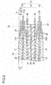
- the battery 100 includes a power generation element (stacked body) 70 in which the electrodes 10 (the positive electrodes 20 and negative electrodes 30) are stacked with separators 40 therebetween, and a casing 80 that seals the power generation element 70.
- a power generation element stacked body 70 in which the electrodes 10 (the positive electrodes 20 and negative electrodes 30) are stacked with separators 40 therebetween, and a casing 80 that seals the power generation element 70.
- the battery 100 has a flat rectangular shape, and a positive electrode tab 24 and a negative electrode tab 34, for outputting electric power, extend from two opposing ends thereof.
- the power generation element 70 is sealed in a state in which the positive electrode tab 24 and the negative electrode tab 34 extend to the outside.
- the battery 100 may be made of known materials that are used for general non-aqueous electrolyte secondary batteries, and the materials are not particularly limited.
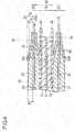
- the electrode 10 (the positive electrode 20 or the negative electrodes 30) includes the current collector 21 or 31, the active material layer 22 or 32, and the insulating member 50.
- the active material layer 22 is stacked on the current collector 21 so as to leave an exposed portion 21b, at which a part of the current collector 21 is exposed.
- the active material layer 22 is stacked so as to form an inclined portion 25 that is inclined in such a way that the thickness thereof decreases toward the exposed portion 21b.
- the active material layer 32 is stacked on the current collector 31 so that an end portion 35 coincides.
- Examples of a method for stacking the active material layer 22 or 32 include a method of applying an electrode slurry to the current collector 21 or 31 and drying the slurry; and a method of stacking an active material layer, which has been formed independently, on the current collector as described in Japanese Unexamined Patent Application Publication No. 2012-238469 .
- the insulating member 50 covers a boundary portion 23 between the active material layer 22 on the current collector 21 and the exposed portion 21b.
- the sum Tg of the thickness Ta of an end portion 22a of the active material layer 22 covered by the insulating member 50 and the stacking-direction-component Tz of the thickness of the insulating member 50 is less than or equal to the thickness T of the active material layer 22 that is not covered by the insulating member 50.
- the current collector and the active material layer on which the insulating member 50 is disposed are the current collector 21 and the active material layer 22 for the positive electrode 20.
- the material of the current collector 21 of the positive electrode 20 materials that have been conventionally used for collectors of batteries can be used as appropriate.
- the material include aluminum, nickel, iron, stainless steel (SUS), titanium, and copper.
- the material of the current collector 21 of the positive electrode 20 is aluminum.
- the material is not particularly limited thereto.
- an aluminum foil, a clad metal of nickel and aluminum, a clad metal of copper and aluminum, or a plating material that is a composite of these metals can be also used.
- the thickness of the current collector of the positive electrode is not particularly limited and is set in consideration of the intended use of the battery.
- the material of the active material layer 22 of the positive electrode 20 is, for example, LiMn 2 O 4 .
- the material is not particularly limited thereto.
- a lithium-transition metal composite oxide is used.
- the positive electrode 20 has the active material layers 22 stacked on both surfaces of the current collector 21 is described.
- the material of the active material layer 32 of the negative electrode 30 is, for example, hard carbon (non-graphitizable carbon material) .
- the material is not particularly limited to this.
- a graphite-based material or a lithium transition-metal oxide can be also used.
- a negative electrode active material that is made of carbon and a lithium transition-metal oxide is preferable in view of capacity and output power characteristics.
- the negative electrode 30 has the active material layers 32 stacked on both surfaces of the current collector 31 is described.
- adjacent electrodes are basically separated by the separator, the electrodes may contact each other via a foreign matter, which has accidentally entered during manufacturing, and a short circuit may occur. Moreover, if displacement in an in-plane direction occurs due to vibration or the like, adjacent electrodes may contact each other and a short circuit may occur. Against such a situation, by disposing the insulating member at a position that overlaps a region formed by the active material layer of the negative electrode in plan view seen in a direction intersecting an in-plane direction, even if displacement occurs, the insulating member can exist between the adjacent electrodes and can prevent occurrence of a short circuit.
- the separator 40 is porous and has air-permeability.
- the separator 40 is impregnated with an electrolyte and serves as an electrolyte layer.
- the material of the separator 40 which is an electrolyte layer, is, for example, air permeable porous PE (polyethylene) that can be impregnated with an electrolyte.
- PE polyethylene
- the material is not particularly limited thereto.
- another polyolefin such as PP (polypropylene), a laminate having three layers of PP/PE/PP, polyamide, polyimide, aramid, or non-woven fabric, can be also used.
- the non-woven fabric is, for example, formed of cotton, rayon, acetate, nylon, or polyester.
- the host polymer of the electrolyte is, for example, PVDF-HFP (copolymer of polyvinylidene fluoride and hexafluoropropylene) containing HFP (hexafluoropropylene) copolymer by 10%.
- the material is not particularly limited thereto.
- Another polymer that does not have lithium-ion conductivity or a polymer that has ion conductivity can be also used.
- Examples of another polymer that does not have lithium-ion conductivity include PAN (polyacrylonitrile) and PMMA (polymethyl methacrylate).
- Examples of a polymer that has ion conductivity include PEO (polyethylene oxide) and PPO (polypropylene oxide).
- An electrolyte solution held by the host polymer includes, for example, an organic solvent, which is composed of PC (propylene carbonate) and EC (ethylene carbonate), and a lithium salt (LiPF 6 ) as a supporting salt.
- the organic solvent is not particularly limited to PC and EC.
- the lithium salt is not particularly limited to LiPF 6 .
- Another inorganic acid anionic salt; or an organic acid anionic salt, such as LiCF 3 SO 3 can be used.
- the insulating member 50 prevents occurrence of an internal short circuit, which may occur if the positive electrode 20 and the negative electrode 30 are displaced from each other beyond the separator 40 and contact each other when forming the battery 100 by stacking the positive electrode 20, the separator 40, and the negative electrode 30.
- the insulating member 50 is disposed on a part of the exposed portion 21b of the current collector 21 of the positive electrode 20, the part facing the active material layer 32 of the negative electrode 30 with the separator 40 therebetween.
- the insulating member 50 covers a region from the exposed portion 21b to the inclined portion 25. That is, the insulating member 50 does not cover a flat portion 26 of the active material layer 22, which is disposed flatly.
- the insulating member 50 extends beyond the end portion 35 of the current collector 31 or the active material layer 32 of the negative electrode 30 in an in-plane direction. With this structure, occurrence of an internal short circuit can be appropriately prevented.
- the positive electrode tab (tab) 24 is connected to an end portion of the current collector 21 of the positive electrode 20, and the insulating member 50 is disposed on the active material layer 22 at a side to which the positive electrode tab 24 is connected.
- the insulating members 50 are disposed at at least two sides of the boundary portion 23 of the rectangular current collector 21 of the positive electrode 20 is described, one of the sides being connected to the positive electrode tab 24 and the other side facing the one of the sides.
- the material of the substrate of the insulating member 50 is a thermoplastic resin.
- the substrate of the insulating member 50 include polyethylene (PE), polypropylene (PP), polyvinyl chloride (PVC), polystyrene (PS), polyvinyl acetate (PVAc), polytetrafluoroethylene (PTFE), acrylonitrile butadiene styrene resin (ABS resin), acrylonitrile styrene resin (AS resin), acrylic resin (PMMA), polyamide (PA), polyacetal (POM), polycarbonate (PC), polyphenylene ether (PPE), polybutylene terephthalate (PBT), polyethylene terephthalate (PET), glass-fiber-reinforced polyethylene terephthalate (GF-PET), cyclic polyolephin (COP), polyphenylene sulfide (PPS), polysulfone (PSF), polyether sulfone (PES), amorphous polyarylate (P
- An adhesive (not shown) applied to the substrate of the insulating member 50 is not particularly limited.
- an organic-solvent-based binder non-aqueous binder
- a water dispersible binder aqueous binder
- Examples of the material include the following: polyethylene, polypropylene, polyethylene terephthalate, polyethernitrile, polyacrylonitrile, polyimide, polyamide, cellulose, carboxymethyl cellulose, ethylene-vinyl acetate copolymer, polyvinyl chloride, styrene-butadiene rubber, isoprene rubber, butadiene rubber, ethylene-propylene rubber, ethylene-propylene-diene copolymer, thermoplastic polymers such as styrene-butadiene-styrene-block copolymer and hydrogenated substances thereof, styrene-isoprene-styrene-block copolymer and hydrogenated substances thereof, polyvinylidene fluoride (PVDF), polytetrafluoroethylene, tetrafluoroethylene-hexafluoropropylene copolymer, tetrafluoroethylene-perfluoroalkyl vinyl ether copoly
- polyvinylidene fluoride, polyimide, styrene-butadiene rubber, carboxymethyl cellulose, polypropylene, polytetrafluoroethylene, polyacrylonitrile, or polyamide is more preferable.
- Such appropriate binders have excellent heat resistance, low reactivity with an electrolyte solution, and excellent solvent resistance, and can be used by being applied to the active material layer of each of the positive electrode and the negative electrode. These binders may be used solely or two or more of the binders may be used together.
- an adhesive tape is used as the insulating member 50.
- the adhesive tape has an adhesive that has been applied to the entirety of one surface thereof that contacts the active material layer 22 of the positive electrode 20.
- the adhesive tape is not limited to this.
- a tape that does not have an adhesive applied thereto can be also used as the substrate of the insulating member 50.
- an adhesive surface is formed by applying an adhesive to the entirety of one surface of the substrate of the insulating member 50, which is made from a tape, the one surface contacting the active material layer 22 of the positive electrode 20.
- the insulating member 50 which has an adhesive surface on the entirety of one surface thereof that contacts the active material layer 22 of the positive electrode 20, is formed.
- the sum Tg of the thickness Ta of the end portion 22a of the active material layer 22 covered by the insulating member 50 and the stacking-direction-component Tz of the thickness of the insulating member 50 is less than or equal to the thickness T of the active material layer 22 that is not covered by the insulating member 50. Therefore, even when the insulating member 50 is disposed on the end portion 22a of the active material layer 22 on the current collector 21 of the positive electrode 20, pressure applied to the positive electrode 20 and the negative electrode 30 becomes uniform. Accordingly, electrical reactions that occur in the positive electrode 20 and the negative electrode 30 become uniform.
- the active material layer 22 of the positive electrode 20 includes the inclined portion 25, which is a part of the active material layer 22 that is covered by the insulating member 50 and that is inclined toward the outer periphery. Therefore, the end portion 22a of the active material layer 22 of the positive electrode 20 does not have a bulge that sticks out in the stacking direction. Accordingly, as compared with a case where the end portion of the active material layer has a bulge that sticks out in the stacking direction, the electrode 10 according to the present invention, which does not have such a bulge at the end portion, can appropriately prevent a short circuit that might be caused by such a bulge.
- the internal volume of the casing 80 is greater than the volume of the power generation element 70, so that the power generation element 70 can be enclosed in the casing 80.
- the internal volume of the casing 80 is the volume of the casing 80 after the casing 80 is sealed and before the casing 80 is vacuumed.
- the volume of the power generation element 70 is the volume of a space occupied by the power generation element 70, including a void inside the power generation element 70. Because the internal volume of the casing 80 is greater than the volume of the power generation element 70, a space that can store a gas when the gas is generated exists. Thus, the gas can be smoothly discharged from the power generation element 70, so that the generated gas is not likely to affect the operation of the battery and the battery characteristics are improved.
- the ratio (L/V 1 ) of the volume L of electrolyte solution injected into the casing 80 to the volume V 1 of the void in the power generation element 70 is in the range of 1.2 to 1.6.
- the amount of electrolyte solution (volume L) is large, even if the electrolyte solution mainly exists on the positive electrode 20 side, a sufficient amount of electrolyte solution exists also on the negative electrode 30 side, which is advantageous in view of uniformly forming surface coatings on both electrodes.
- the amount of electrolyte solution (volume L) is large, the cost of electrolyte solution is increased.
- the value of the ratio (L/V 1 ) is preferably in the range of 1.2 to 1.6, more preferably in the range of 1.25 to 1.55, and particularly preferably in the range of 1.3 to 1.5.
- the ratio of (V 2 /V 1 ) the volume V 2 of an extra space 81 in the casing 80 to the volume V 1 of a void in the power generation element 70 is in the range of 0.5 to 1.0.
- the ratio (L/V 2 ) of the volume L of electrolyte solution injected into the casing 80 to the volume V 2 of the extra space 81 in the casing 80 is in the range of 0.4 to 0.7.
- the volume (V 1 ) of the void in the power generation element 70 can be calculated by adding up the volumes of voids in the positive electrode 20, the negative electrode 30, and the separator 40. That is, the volume (V 1 ) can be calculated as the sum of the volumes of voids in the components of the power generation element 70.
- the battery 100 is usually made by enclosing the power generation element 70 in the casing 80, injecting the electrolyte solution into the casing 80, and vacuuming the inside of the casing 80. When a gas is generated in the casing 80 in this state, if there is a space for storing the generated gas in the casing 80, the casing 80 expands due to the generated gas stored in the space.
- V 2 the volume of the extra space when the casing expands to the maximum without bursting.
- V 2 /V 1 the value of V 2 /V 1 is preferably in the range of 0.5 to 1.0, more preferably in the range of 0.6 to 0.9, and particularly preferably in the range of 0.7 to 0.8.
- the ratio of the volume of the electrolyte solution injected and the volume of the extra space 81 is controlled to be in a predetermined range.
- the extra space 81 in the casing 80 is at least disposed vertically above the power generation element 70.
- the generated gas can be stored in a vertically-upper part of the power generation element 70, in which the extra space 81 exists.
- the electrolyte solution can mainly exist in a lower part of the casing 80 in which the power generation element 70 exists.
- the power generation element 70 can be constantly and reliably immersed in a larger amount of electrolyte solution, and decrease of battery performance due to shortage of electrolyte solution can be minimized.
- a specific structure for allowing the extra space 81 to be disposed vertically above the power generation element 70 is not particularly limited.
- the material and shape of the casing 80 itself may be determined so that the casing 80 may not bulge toward a side part or a lower part of the power generation element 70, or a member for preventing the casing 80 from bulging toward the side part or the lower part thereof may be disposed outside the casing 80.
- the battery 100 including the electrode 10 according to the present invention is particularly advantageous in a case where the battery 100 is a large-area battery in which the active material layer 22 of the positive electrode 20 and the active material layer 32 of the negative electrode 30 both have large areas. That is, in the case where the battery 100 is a large-area battery, the battery 100 is advantageous in that cohesive failure from an electrode surface due to friction between the electrode 10 (the positive electrode 20 or the negative electrode 30) and the separator 40 can be further suppressed, and the battery characteristics can be maintained even if vibration is applied.
- the battery assembly including the power generation element 70 and the casing 80 covering the power generation element 70, is large, because the present embodiment is more advantageous in this case.
- the active material layer of the electrode 10 (the positive electrode 20 or the negative electrode 30) is shaped like a rectangle, and the length of a short side of the rectangle is 100 mm or greater.
- the length of the short side of the active material layer 32 of the negative electrode 30 refers to the length of the shortest one of the sides of each electrode.
- the upper limit of the length of the short side of the battery assembly is not particularly limited. Usually, the length is 250 mm or less.
- upsizing of the battery can be defined in terms of the relationship between the area and the capacity of the battery.
- the ratio of the area of the battery (the projected area of the battery including the casing) to the rated capacity is 5 cm 2 /Ah or greater, and the rated capacity is 3 Ah or greater.
- a problem of decrease of the battery performance (in particular, life characteristics after a long cycle) of a large battery in which an aqueous binder such as SBR is used to form the active material layer of the negative electrode is more likely to arise.
- a non-aqueous electrolyte secondary battery according to the present embodiment is large in the respect that the advantages of the present invention are more significant.
- the aspect ratio of the rectangular electrode is in the range of 1 to 3, and preferably in the range of 1 to 2.
- the aspect ratio of the electrode is defined as the ratio of a long side to a short side of the rectangular active material layer of the positive electrode.
- the gas can be discharged uniformly in an in-plane injected into a test battery, the test battery is let stand for about 10 hours, and an initial charge is performed. Subsequently, at a temperature of 25°C and in a voltage range of 3.0 V to 4.15 V, the rated capacity is measured through the following steps 1 to 5.
- Step 1 A constant-current charge of 0.2 C is performed so that the voltage reaches 4.15 V, and then a 5-minute break is taken.
- Step 2 After step 1, a constant-voltage charge is performed for 1.5 hours, and then a 5-minute break is taken.
- Step 3 A constant-current discharge of 0.2 C is performed so that the voltage reaches 3.0 V, a constant-voltage discharge is performed for 2 hours, and a 10-second break is taken.
- Step 4 A constant-current charge of 0.2 C is performed so that the voltage reaches 4.1 V, a constant-voltage charge is performed for 2.5 hours, and then a 10-second break is taken.
- Step 5 A constant-current discharge of 0.2 C is performed so that the voltage reaches 3.0 V, a constant-voltage discharge is performed for 2 hours, and then a 10-second break is taken.
- the rated capacity is the discharge capacity (CCCV discharge capacity) from the constant-current discharge to the constant-voltage discharge in Step 5.
- the electrode 10 according to the first embodiment described above has the following advantages.
- the electrode 10 (the positive electrode 20) includes the current collector 21, the active material layer 22, and the insulating member 50.
- the active material layer 22 is stacked on the current collector 21 so as to form the inclined portions 25 while leaving the exposed portion 21b at which a part of the current collector 21 is exposed, the inclined portion 25 being inclined in such a way that a thickness thereof decreases toward the exposed portion 21b.
- the insulating member 50 covers the region from the exposed portion 21b to the inclined portion 25.
- the electrode 10 having such a structure, even though the insulating member 50 is disposed on the end portion 22a of the active material layer 22 on the current collector 21, nonuniformity in the pressure applied to the electrode 10 (the positive electrode 20 or the negative electrode 30) can be reduced. Accordingly, the electrode 10 (the positive electrode 20) according to the present invention can reduce nonuniformity in electrode reactions, and, as a result, can improve the cycle characteristics.
- the sum Tg of the thickness Ta of the end portion 22a of the active material layer 22 covered by the insulating member 50 and the stacking-direction-component Tz of the thickness of the insulating member 50 is less than or equal to the thickness T of the active material layer 22 that is not covered by the insulating member 50.
- the electrode 10 having such a structure, when disposing the insulating member 50 from the active material layer 22 on the current collector 21 to the exposed portion 21b of the electrode 10 (the positive electrode 20), the sum Tg of the thickness Ta of the end portion 22a of the active material layer 22 covered by the insulating member 50 and the stacking-direction-component Tz of the thickness of the insulating member 50 is made less than or equal to the thickness T of the active material layer 22 that is not covered by the insulating member 50. Therefore, even though the insulating member 50 is disposed on the end portion 22a of the active material layer 22 on the current collector 21, the electrode 10 (the positive electrode 20) according to the present invention can make pressure applied to the electrode 10 (the positive electrode 20 or the negative electrode 30) be uniform.
- the electrode 10 (the positive electrode 20 or the negative electrode 30) according to the present invention can cause electrode reactions uniformly, and, as a result, can improve the cycle characteristics.
- the electrode 10 when forming the battery 100 by stacking the positive electrodes 20, the separators 40, and the negative electrodes 30, it is possible to prevent the height of the battery 100 in the stacking direction at end portions of the electrodes 10 in an in-plane direction from becoming greater than the height of portions other than the end portions. Accordingly, flexible layout of the battery 100 can be provided.
- the insulating member 50 extends beyond the end portion 35 of the current collector 31 or the active material layer 32 of the negative electrode 30 in an in-plane direction.
- the electrode 10 (the positive electrode 20) having such a structure, occurrence of the internal short circuit can be appropriately prevented.
- the positive electrode tab (tab) 24 is connected an end portion of the current collector 21, and the insulating member 50 is disposed on the active material layer 22 at a side to which the positive electrode tab 24 is connected.
- the electrode 10 (the positive electrode 20) having such a structure, because the insulating member 50 is disposed on the end portion 22a of the active material layer 22 at the side to which the positive electrode tab 24 is connected, nonuniformity in the pressure applied to a part of the active material layer 22 near the positive electrode tab 24 can be reduced. Therefore, the electrode 10 (the positive electrode 20) according to the present invention can reduce nonuniformity in an electrode reaction in the part of the active material layer 22 of the positive electrode 20 near the positive electrode tab 24 and allows an electric current to smoothly flow to the positive electrode tab 24. Accordingly, the electrode 10 (the positive electrode 20) according to the present invention can improve the cycle characteristics.
- the current collector and the active material layer of the electrode 10 are for the positive electrode 20.
- the insulating member 50 is included in the positive electrode 20. Therefore, in the present embodiment, the current collector and the active material layer on which the insulating member 50 is disposed are the current collector 21 and the active material layer 22 for the positive electrode 20.
- the insulating member 50 included in the positive electrode 20 can reduce nonuniformity in the pressure applied to the positive electrode 20 and the negative electrode 30 and can reduce nonuniformity in electrode reactions. Accordingly, with the battery 100, the cycle characteristics can be improved.
- the insulating member 50 is disposed at a position that overlaps a region formed by the active material layer 32 of the negative electrode 30 in plan view.
- the electrodes may contact each other if displacement in an in-plane direction occurs due to vibration or the like, and a short circuit may occur.
- the insulating member 50 is disposed at the position that overlaps the region formed by the active material layers 32 of the negative electrode 30 in plan view seen in a direction intersecting the in-plane direction.
- the battery 100 includes the stacked body (the power generation element 70), in which the electrodes 10 (the positive electrodes 20 and the negative electrodes 30) are stacked with the separators 40 therebetween; and the casing 80, which seals stacked body.
- the battery 100 having such a structure, because the electrode 10 (the positive electrode 20) is enclosed in the casing 80, even though the insulating member 50 is disposed on the end portion 22a of the active material layer 22 on the current collector 21, nonuniformity in the pressure applied to the electrode 10 (the positive electrode 20 or the negative electrode 30) can be reduced. Accordingly, the battery 100 can reduce nonuniformity in the electrode reaction, and, as a result, can improve the cycle characteristics.
- the active material layers 22 and 32 are each shaped like a rectangle, and the length of a short side of the rectangle is 100 mm or greater.
- the active material layer 22 of the positive electrode 20 and the active material layer 32 of the negative electrode 30 are each shaped like a rectangle having a short side whose length is 100 mm or greater.
- the ratio of the area of the battery (the projected area of the battery 100 including the casing 80) to the rated capacity is 5 cm 2 /Ah or greater, and the rated capacity is 3 Ah or greater.
- upsizing of the battery 100 can be defined in terms of the relationship of the battery area and the battery capacity.
- the aspect ratio of the electrode 10 which is defined as the ratio of a long side to a short side of the active material layer 22 of the rectangular positive electrode 20, is in the range of 1 to 3.
- the electrode 10 having such a structure, by setting the aspect ratio to be in such a range, a gas can be discharged uniformly in an in-plane direction.
- the current collector 21 of the positive electrode 20 is an Al foil having a thickness of 20 ⁇ m.
- the active material layer 22 (positive electrode slurry) of the positive electrode 20 is made by dispersing lithium nickel oxide powder (active material), PVdF (polyvinylidene fluoride, binder), carbon powder (conductive assistant) with a ratio of 90:5:5 (weight ratio) in NMP (N-methylpyrrolidone). Subsequently, the positive electrode slurry is applied to both surfaces of the Al foil having a thickness of 20 ⁇ m by using a die coater, dried, and then pressed. Thus, the positive electrode 20, having a thickness of 150 ⁇ m except for the end portion 22a of the active material layer 22, is formed.
- the current collector 31 of the negative electrode 30 is a Cu foil having a thickness of 10 ⁇ m.
- the active material layer 32 (negative electrode slurry) of the negative electrode 30 is made by dispersing Gr powder (active material) and PVdF (polyvinylidene fluoride, binder) with a ratio of 95:5 (weight ratio) in NMP (N-methylpyrrolidone). Subsequently, the negative electrode slurry is applied to both surfaces of the Cu foil having a thickness of 10 ⁇ m by using a die coater, dried, and then pressed. Thus, the negative electrode 30, having a thickness of 140 ⁇ m, is formed.
- a method of forming the battery 100 will be described.
- a polypropylene tape having a width of 12 mm and a thickness of 30 ⁇ m is used so as to cover the boundary between the active material layer 22 on the current collector 21 of the positive electrode 20 and the exposed portion 21b.
- a method of affixing the tape and the covering length are shown in results 1-*.
- the battery 100 which had been formed, was clamped between SUS plates having a thickness of 5 mm so that a pressure of 100 g/cm 2 was applied to the battery, and 0.2C/4.2V_CC/CV charge was performed for seven hours at 25°C. Next, a 10-minute break was taken, and then discharge was performed to 2.5V with 0.2C_CC discharge. Subsequently, in 55°C atmosphere, a cycle of 1C/4.2V_CC/CV charge (0.015 C cut) and 1C_CC discharge (2.5 V voltage cut) was repeated (cycle test), and the ratio of the discharge capacity in the 300-th cycle to the discharge capacity in the first cycle was calculated as the cycle capacity retention ratio.
- the active material layer 22 was applied to the current collector 21 so that the thickness Ta of the end portion 22a of the active material layer 22 of the positive electrode 20 at a position of 2.5 mm from the outer peripheral end was 140 ⁇ m or less.
- the sum Tg of the thickness Ta of the end portion 22a of the active material layer 22 covered by the insulating member 50 and the stacking-direction-component Tz of the thickness of the insulating member 50 was 150 ⁇ m at the maximum (thickness the same as the thickness T of the active material layer 22 that was not covered by the insulating member 50).
- the active material layer 22 of the positive electrode 20 was formed in a square shape having a size of 190 mm ⁇ 190 mm.
- the positive electrode 20 had an aspect ratio of 1:1.
- the active material layer 32 of the negative electrode 30 was formed in a square shape having a size of 200 mm ⁇ 200 mm.
- the power generation element 70 was formed by using the positive electrode 20 and the negative electrode 30 having such sizes, and the cycle test was performed. As a result, the cycle capacity retention ratio was 82%.
- the active material layer 22 was applied to the current collector 21 so that the thickness Ta of the end portion 22a of the active material layer 22 of the positive electrode 20 at a position of 2.5 mm from the outer peripheral end was 130 ⁇ m or less.
- the sum Tg of the thickness Ta of the end portion 22a of the active material layer 22 covered by the insulating member 50 and the stacking-direction-component Tz of the thickness of the insulating member 50 was 140 ⁇ m at the maximum (thickness less than the thickness T of the active material layer 22 that was not covered by the insulating member 50).
- the active material layer 22 of the positive electrode 20 was formed in a square shape having a size of 190 mm ⁇ 190 mm.
- the positive electrode 20 had an aspect ratio of 1:1.
- the active material layer 32 of the negative electrode 30 was formed in a square shape having a size of 200 mm ⁇ 200 mm.
- the power generation element 70 was formed by using the positive electrode 20 and the negative electrode 30 having such sizes, and the cycle test was performed. As a result, the cycle capacity retention ratio was 82%.
- the active material layer 22 was applied to the current collector 21 so that the thickness Ta of the end portion 22a of the active material layer 22 of the positive electrode 20 at a position of 2.5 mm from the outer peripheral end was 140 ⁇ m or less.
- the sum Tg of the thickness Ta of the end portion 22a of the active material layer 22 covered by the insulating member 50 and the stacking-direction-component Tz of the thickness of the insulating member 50 was 150 ⁇ m at the maximum (thickness the same as the thickness T of the active material layer 22 that was not covered by the insulating member 50).
- the active material layer 22 of the positive electrode 20 was formed in a rectangular shape having a size of 190 mm ⁇ 570 mm.
- the positive electrode 20 had an aspect ratio of 1:3.
- the active material layer 32 of the negative electrode 30 was formed in a rectangular shape having a size of 200 mm ⁇ 580 mm.
- the power generation element 70 was formed by using the positive electrode 20 and the negative electrode 30 having such sizes, and the cycle test was performed. As a result, the cycle capacity retention ratio was 81%.
- An active material layer was applied to the current collector so that the thickness of an end portion of the active material layer of the positive electrode was 150 ⁇ m, which was the same as the thickness of the active material layer that was not covered by the insulating member.
- the sum of the thickness of the end portion of the active material layer covered by the insulating member and the stacking-direction-component of the thickness of the insulating member was 160 ⁇ m at the maximum (thickness greater than the thickness of the active material layer that was not covered by the insulating member).
- the active material layer of the positive electrode was formed in a square shape having a size of 190 mm ⁇ 190 mm. Thus, the positive electrode had an aspect ratio of 1:1.
- An active material layer of the negative electrode was formed in a square shape having a size of 200 mm ⁇ 200 mm.
- a power generation element was formed by using the positive electrode and the negative electrode having such sizes, and the cycle test was performed. As a result, the cycle capacity retention ratio was 76%.
- the active material layer was applied to the current collector so that the thickness of the end portion of the active material layer of the positive electrode at a position of 2.5 mm from the outer peripheral end was 145 ⁇ m or less.
- the sum of the thickness of the end portion of the active material layer covered by the insulating member and the stacking-direction-component of the thickness of the insulating member was 155 ⁇ m at the maximum (thickness greater than the thickness of the active material layer that was not covered by the insulating member) .
- An active material layer of the positive electrode was formed in a square shape having a size of 190 mm ⁇ 190 mm.
- the positive electrode had an aspect ratio of 1:1.
- the active material layer of the negative electrode was formed in a square shape having a size of 200 mm ⁇ 200 mm.
- a power generation element was formed by using the positive electrode and the negative electrode having such sizes, and the cycle test was performed. As a result, the cycle capacity retention ratio was 79%.
- the active material layer was applied to the current collector so that the thickness of the end portion of the active material layer of the positive electrode at a position of 2.5 mm from the outer peripheral end was 140 ⁇ m or less.
- the sum of the thickness of the end portion of the active material layer covered by the insulating member and the stacking-direction-component of the thickness of the insulating member was 150 ⁇ m at the maximum (thickness the same as the thickness of the active material layer that was not covered by the insulating member) .
- An active material layer of the positive electrode was formed in a rectangular shape having a size of 190 mm ⁇ 760 mm.
- the positive electrode had an aspect ratio of 1:4.
- An active material layer of the negative electrode was formed in a rectangular shape having a size of 200 mm ⁇ 770 mm.
- a power generation element was formed by using the positive electrode and the negative electrode having such sizes, and the cycle test was performed. As a result, the cycle capacity retention ratio was 78%.
- Table 1 shows the results of testing the cycle capacity retention ratio of the EXAMPLES 1 to 3 and the Comparative Examples 1 to 3.
- Table 1 Maximum Thickness Tg ( ⁇ m) of Part Covered by Insulating Member Aspect Ratio of Positive Electrode Cycle Capacity Retention Ratio (%) EXAMPLE 1 150 1:1 82 EXAMPLE 2 140 1:1 82 EXAMPLE 3 150 1:3 81 Comparative Example 1 160 1:1 76 Comparative Example 2 155 1:1 79 Comparative Example 3 150 1:4 78
- the power generation element 70 is formed by alternately stacking the positive electrode 20, the separator 40, and the negative electrode 30.
- the structure of the power generation element 70 is not limited to this. It has been confirmed that a power generation element 70 in which the positive electrode 20 and the negative electrode 30 are wound with the separator 40 therebetween has the same advantages.
- the insulating member 50 extends beyond the end portion 35 of the current collector 31 or the active material layer 32 of the negative electrode 30 in an in-plane direction.
- the insulating member 50 may extend beyond an end portion 45 of the separator 40 in the in-plane direction.
- the sum of Tg of the thickness Ta of the end portion 22a of the active material layer 22 covered by the insulating member 50 and the stacking-direction-component Tz of the thickness of the insulating member 50 is less than the thickness T of the active material layer 22 that is not covered by the insulating member 50.
- the sum of Tg of the thickness Ta of the end portion 22a and the stacking-direction-component Tz of the thickness of the insulating member 50 may exceed the thickness T of the active material layer 22.
- the electrode 10 is the positive electrode 20.
- the structure is not limited to this, and the electrode 10 may be the negative electrode 30. That is, although not illustrated, an insulating member may be disposed so as to cover a region from an exposed portion of the current collector to an inclined portion of the negative electrode.
- the insulating member 50 is disposed at least at two sides of the boundary portion 23 of the rectangular current collector 21 of the positive electrode 20, one of the sides being connected to the positive electrode tab 24 and the other side facing the one of the sides.
- the structure is not limited to this.
- the insulating member 50 may be disposed at all sides (the entire periphery) of the boundary portion 23 of the rectangular current collector 21 of the positive electrode 20.
Landscapes
- Chemical & Material Sciences (AREA)
- Chemical Kinetics & Catalysis (AREA)
- Electrochemistry (AREA)
- General Chemical & Material Sciences (AREA)
- Engineering & Computer Science (AREA)
- Materials Engineering (AREA)
- Manufacturing & Machinery (AREA)
- Inorganic Chemistry (AREA)
- Physics & Mathematics (AREA)
- Condensed Matter Physics & Semiconductors (AREA)
- General Physics & Mathematics (AREA)
- Secondary Cells (AREA)
- Battery Electrode And Active Subsutance (AREA)
- Connection Of Batteries Or Terminals (AREA)
Applications Claiming Priority (2)
| Application Number | Priority Date | Filing Date | Title |
|---|---|---|---|
| JP2013225825 | 2013-10-30 | ||
| PCT/JP2014/078657 WO2015064586A1 (ja) | 2013-10-30 | 2014-10-28 | 電極、および電極を有する電池 |
Publications (3)
| Publication Number | Publication Date |
|---|---|
| EP3065205A1 EP3065205A1 (en) | 2016-09-07 |
| EP3065205A4 EP3065205A4 (en) | 2016-10-12 |
| EP3065205B1 true EP3065205B1 (en) | 2018-12-05 |
Family
ID=53004188
Family Applications (1)
| Application Number | Title | Priority Date | Filing Date |
|---|---|---|---|
| EP14857195.3A Active EP3065205B1 (en) | 2013-10-30 | 2014-10-28 | Electrode and cell having electrode |
Country Status (6)
| Country | Link |
|---|---|
| US (1) | US20160260978A1 (ja) |
| EP (1) | EP3065205B1 (ja) |
| JP (1) | JP6146478B2 (ja) |
| KR (1) | KR101802102B1 (ja) |
| CN (1) | CN105706275B (ja) |
| WO (1) | WO2015064586A1 (ja) |
Families Citing this family (17)
| Publication number | Priority date | Publication date | Assignee | Title |
|---|---|---|---|---|
| JP6531486B2 (ja) * | 2015-05-20 | 2019-06-19 | 日産自動車株式会社 | 電池 |
| JP6705126B2 (ja) * | 2015-06-04 | 2020-06-03 | 株式会社Gsユアサ | 電極板の製造方法 |
| CN108604664B (zh) * | 2016-02-10 | 2021-11-12 | 株式会社杰士汤浅国际 | 蓄电元件以及蓄电元件的制造方法 |
| US20210210761A1 (en) * | 2016-03-24 | 2021-07-08 | Nec Energy Devices, Ltd. | Lithium ion secondary battery, electrode and method for producing same |
| JP6957837B2 (ja) * | 2016-04-08 | 2021-11-02 | 株式会社Gsユアサ | 蓄電素子 |
| US10707531B1 (en) | 2016-09-27 | 2020-07-07 | New Dominion Enterprises Inc. | All-inorganic solvents for electrolytes |
| JP6961398B2 (ja) * | 2017-06-14 | 2021-11-05 | 株式会社エンビジョンAescジャパン | リチウムイオン二次電池素子およびリチウムイオン二次電池 |
| EP3667762A4 (en) * | 2017-08-08 | 2020-08-19 | GS Yuasa International Ltd. | ELECTRICITY STORAGE MODULE AND ELECTRICITY STORAGE ELEMENT |
| US20200373558A1 (en) * | 2018-02-01 | 2020-11-26 | Lg Chem, Ltd. | Electrode for Lithium Secondary Battery, Method of Preparing the Same and Lithium Secondary Battery Including the Same |
| JP6876880B2 (ja) * | 2018-09-28 | 2021-05-26 | 積水化学工業株式会社 | リチウムイオン二次電池用電極、及びリチウムイオン二次電池 |
| JP6983147B2 (ja) * | 2018-12-26 | 2021-12-17 | 本田技研工業株式会社 | 固体電池用電極および固体電池 |
| JP7178633B2 (ja) | 2018-12-27 | 2022-11-28 | パナソニックIpマネジメント株式会社 | 全固体電池およびその製造方法 |
| CN115380397A (zh) * | 2020-03-30 | 2022-11-22 | 宁德新能源科技有限公司 | 电池组件、应用所述电池组件的电池及电子装置 |
| CN115428223A (zh) | 2020-05-12 | 2022-12-02 | 松下知识产权经营株式会社 | 电池 |
| JP7318598B2 (ja) * | 2020-07-03 | 2023-08-01 | トヨタ自動車株式会社 | 固体電池 |
| WO2023068875A1 (ko) * | 2021-10-21 | 2023-04-27 | 주식회사 엘지에너지솔루션 | 전극 조립체 및 이를 포함하는 전지 셀 |
| US20240079656A1 (en) * | 2021-12-06 | 2024-03-07 | Lg Energy Solution, Ltd. | Electrode Assembly, Manufacturing Method Thereof, and Lithium Secondary Battery Comprising the Same |
Citations (1)
| Publication number | Priority date | Publication date | Assignee | Title |
|---|---|---|---|---|
| US20040106038A1 (en) * | 2002-08-05 | 2004-06-03 | Nissan Motor Co., Ltd. | Automobile cell and related method |
Family Cites Families (15)
| Publication number | Priority date | Publication date | Assignee | Title |
|---|---|---|---|---|
| US20020019753A1 (en) * | 2000-08-07 | 2002-02-14 | Boden John B. | System, method, and computer program product for assisting caregivers |
| US7097673B2 (en) * | 2001-06-07 | 2006-08-29 | 3M Innovative Properties Company | Coating edge control |
| JP4201619B2 (ja) | 2003-02-26 | 2008-12-24 | 三洋電機株式会社 | 非水電解質二次電池、及びそれに使用する電極の製造方法 |
| JP2005149891A (ja) * | 2003-11-14 | 2005-06-09 | Nissan Motor Co Ltd | バイポーラ電池、及びそれを用いた組電池 |
| JP2006147392A (ja) * | 2004-11-22 | 2006-06-08 | Matsushita Electric Ind Co Ltd | 電池 |
| US8628876B2 (en) * | 2008-06-20 | 2014-01-14 | Samsung Sdi Co., Ltd. | Electrode assembly and lithium secondary battery with same |
| JP5509561B2 (ja) * | 2008-09-17 | 2014-06-04 | 日産自動車株式会社 | 非水電解質二次電池 |
| JP5858325B2 (ja) * | 2010-09-03 | 2016-02-10 | 株式会社Gsユアサ | 電池 |
| JP5818150B2 (ja) * | 2010-11-05 | 2015-11-18 | 株式会社Gsユアサ | 蓄電素子用電極、それを用いた蓄電素子、および蓄電素子用電極の製造方法 |
| JP5830953B2 (ja) * | 2010-11-17 | 2015-12-09 | ソニー株式会社 | 二次電池、バッテリユニットおよびバッテリモジュール |
| JP5844052B2 (ja) * | 2011-02-04 | 2016-01-13 | 三洋電機株式会社 | 積層式電池およびその製造方法 |
| JP5590333B2 (ja) * | 2011-02-25 | 2014-09-17 | 日立オートモティブシステムズ株式会社 | リチウムイオン二次電池およびその正極 |
| JP5768483B2 (ja) | 2011-05-11 | 2015-08-26 | 日産自動車株式会社 | 電気デバイスに用いられる電極 |
| CN107170950A (zh) * | 2012-06-11 | 2017-09-15 | Nec能源元器件株式会社 | 电极制造方法 |
| WO2015015663A1 (ja) * | 2013-07-31 | 2015-02-05 | Necエナジーデバイス株式会社 | 二次電池 |
-
2014
- 2014-10-28 US US15/032,139 patent/US20160260978A1/en not_active Abandoned
- 2014-10-28 KR KR1020167010142A patent/KR101802102B1/ko active IP Right Grant
- 2014-10-28 JP JP2015545241A patent/JP6146478B2/ja active Active
- 2014-10-28 WO PCT/JP2014/078657 patent/WO2015064586A1/ja active Application Filing
- 2014-10-28 EP EP14857195.3A patent/EP3065205B1/en active Active
- 2014-10-28 CN CN201480058808.3A patent/CN105706275B/zh active Active
Patent Citations (1)
| Publication number | Priority date | Publication date | Assignee | Title |
|---|---|---|---|---|
| US20040106038A1 (en) * | 2002-08-05 | 2004-06-03 | Nissan Motor Co., Ltd. | Automobile cell and related method |
Also Published As
| Publication number | Publication date |
|---|---|
| JPWO2015064586A1 (ja) | 2017-03-09 |
| WO2015064586A1 (ja) | 2015-05-07 |
| CN105706275A (zh) | 2016-06-22 |
| EP3065205A1 (en) | 2016-09-07 |
| JP6146478B2 (ja) | 2017-06-14 |
| EP3065205A4 (en) | 2016-10-12 |
| US20160260978A1 (en) | 2016-09-08 |
| CN105706275B (zh) | 2019-04-09 |
| KR101802102B1 (ko) | 2017-11-27 |
| KR20160060096A (ko) | 2016-05-27 |
Similar Documents
| Publication | Publication Date | Title |
|---|---|---|
| EP3065205B1 (en) | Electrode and cell having electrode | |
| JP6003041B2 (ja) | 耐熱絶縁層付セパレータ | |
| JP6521323B2 (ja) | 二次電池とその製造方法 | |
| JP6264891B2 (ja) | 電極、および電極を有する電池 | |
| WO2013051416A1 (ja) | 電気デバイス | |
| WO2016079581A1 (en) | Nonaqueous electrolyte secondary battery | |
| JP6531486B2 (ja) | 電池 | |
| JP5347428B2 (ja) | 二次電池 | |
| JP2019067653A (ja) | 非水電解液二次電池 | |
| JP2010161249A (ja) | リチウムイオンキャパシタ | |
| US6258487B1 (en) | Lithium secondary battery including a divided electrode base layer | |
| JP6606341B2 (ja) | 電極および電池 | |
| CN110476278B (zh) | 电极和蓄电元件 | |
| JP2022188177A (ja) | フィルム外装電池、組電池および前記フィルム外装電池の製造方法 | |
| JP2013127845A (ja) | 電気デバイス | |
| CN112018447A (zh) | 锂离子二次电池元件、电池和制造该电池元件的方法 | |
| JP7405243B2 (ja) | 集電体、蓄電素子及び蓄電モジュール | |
| KR101089161B1 (ko) | 파우치형 이차전지 | |
| KR101515672B1 (ko) | 2 이상의 양극 및 음극을 포함하는 전극 조립체 및 이에 의한 전기 화학 소자 | |
| CN115461909A (zh) | 一种电化学装置及包含该电化学装置的电子装置 | |
| JP2011222128A (ja) | 二次電池 | |
| JP2021144889A (ja) | 電池の製造方法および電池 | |
| CN111066175A (zh) | 非水电解液二次电池 | |
| KR101489037B1 (ko) | 리드 부재를 포함하는 이차전지 | |
| JP7365566B2 (ja) | 非水電解液二次電池 |
Legal Events
| Date | Code | Title | Description |
|---|---|---|---|
| PUAI | Public reference made under article 153(3) epc to a published international application that has entered the european phase |
Free format text: ORIGINAL CODE: 0009012 |
|
| 17P | Request for examination filed |
Effective date: 20160418 |
|
| AK | Designated contracting states |
Kind code of ref document: A1 Designated state(s): AL AT BE BG CH CY CZ DE DK EE ES FI FR GB GR HR HU IE IS IT LI LT LU LV MC MK MT NL NO PL PT RO RS SE SI SK SM TR |
|
| AX | Request for extension of the european patent |
Extension state: BA ME |
|
| A4 | Supplementary search report drawn up and despatched |
Effective date: 20160909 |
|
| RIC1 | Information provided on ipc code assigned before grant |
Ipc: H01M 10/0525 20100101ALI20160905BHEP Ipc: H01M 4/13 20100101AFI20160905BHEP Ipc: H01M 10/04 20060101ALI20160905BHEP Ipc: H01M 2/26 20060101ALI20160905BHEP Ipc: H01M 10/0585 20100101ALN20160905BHEP Ipc: H01M 4/02 20060101ALI20160905BHEP Ipc: H01M 2/06 20060101ALI20160905BHEP Ipc: H01M 2/34 20060101ALI20160905BHEP |
|
| DAX | Request for extension of the european patent (deleted) | ||
| STAA | Information on the status of an ep patent application or granted ep patent |
Free format text: STATUS: EXAMINATION IS IN PROGRESS |
|
| 17Q | First examination report despatched |
Effective date: 20170609 |
|
| GRAP | Despatch of communication of intention to grant a patent |
Free format text: ORIGINAL CODE: EPIDOSNIGR1 |
|
| STAA | Information on the status of an ep patent application or granted ep patent |
Free format text: STATUS: GRANT OF PATENT IS INTENDED |
|
| RIC1 | Information provided on ipc code assigned before grant |
Ipc: H01M 10/0525 20100101ALI20180425BHEP Ipc: H01M 2/34 20060101ALI20180425BHEP Ipc: H01M 2/26 20060101ALI20180425BHEP Ipc: H01M 4/13 20100101AFI20180425BHEP Ipc: H01M 2/06 20060101ALI20180425BHEP Ipc: H01M 10/04 20060101ALI20180425BHEP Ipc: H01M 4/02 20060101ALI20180425BHEP Ipc: H01M 10/0585 20100101ALN20180425BHEP |
|
| RIC1 | Information provided on ipc code assigned before grant |
Ipc: H01M 4/02 20060101ALN20180507BHEP Ipc: H01M 4/13 20100101AFI20180507BHEP Ipc: H01M 2/26 20060101ALI20180507BHEP Ipc: H01M 10/0525 20100101ALI20180507BHEP Ipc: H01M 10/04 20060101ALN20180507BHEP Ipc: H01M 2/06 20060101ALI20180507BHEP Ipc: H01M 10/0585 20100101ALI20180507BHEP |
|
| INTG | Intention to grant announced |
Effective date: 20180522 |
|
| GRAJ | Information related to disapproval of communication of intention to grant by the applicant or resumption of examination proceedings by the epo deleted |
Free format text: ORIGINAL CODE: EPIDOSDIGR1 |
|
| STAA | Information on the status of an ep patent application or granted ep patent |
Free format text: STATUS: EXAMINATION IS IN PROGRESS |
|
| GRAP | Despatch of communication of intention to grant a patent |
Free format text: ORIGINAL CODE: EPIDOSNIGR1 |
|
| STAA | Information on the status of an ep patent application or granted ep patent |
Free format text: STATUS: GRANT OF PATENT IS INTENDED |
|
| INTC | Intention to grant announced (deleted) | ||
| INTG | Intention to grant announced |
Effective date: 20180711 |
|
| RIC1 | Information provided on ipc code assigned before grant |
Ipc: H01M 2/26 20060101ALI20180702BHEP Ipc: H01M 10/0525 20100101ALI20180702BHEP Ipc: H01M 4/02 20060101ALN20180702BHEP Ipc: H01M 10/04 20060101ALN20180702BHEP Ipc: H01M 2/06 20060101ALI20180702BHEP Ipc: H01M 4/13 20100101AFI20180702BHEP Ipc: H01M 10/0585 20100101ALI20180702BHEP |
|
| GRAS | Grant fee paid |
Free format text: ORIGINAL CODE: EPIDOSNIGR3 |
|
| GRAA | (expected) grant |
Free format text: ORIGINAL CODE: 0009210 |
|
| STAA | Information on the status of an ep patent application or granted ep patent |
Free format text: STATUS: THE PATENT HAS BEEN GRANTED |
|
| AK | Designated contracting states |
Kind code of ref document: B1 Designated state(s): AL AT BE BG CH CY CZ DE DK EE ES FI FR GB GR HR HU IE IS IT LI LT LU LV MC MK MT NL NO PL PT RO RS SE SI SK SM TR |
|
| REG | Reference to a national code |
Ref country code: GB Ref legal event code: FG4D |
|
| REG | Reference to a national code |
Ref country code: CH Ref legal event code: EP |
|
| REG | Reference to a national code |
Ref country code: AT Ref legal event code: REF Ref document number: 1074175 Country of ref document: AT Kind code of ref document: T Effective date: 20181215 |
|
| REG | Reference to a national code |
Ref country code: IE Ref legal event code: FG4D |
|
| REG | Reference to a national code |
Ref country code: DE Ref legal event code: R096 Ref document number: 602014037623 Country of ref document: DE |
|
| REG | Reference to a national code |
Ref country code: NL Ref legal event code: MP Effective date: 20181205 |
|
| REG | Reference to a national code |
Ref country code: AT Ref legal event code: MK05 Ref document number: 1074175 Country of ref document: AT Kind code of ref document: T Effective date: 20181205 |
|
| REG | Reference to a national code |
Ref country code: LT Ref legal event code: MG4D |
|
| PG25 | Lapsed in a contracting state [announced via postgrant information from national office to epo] |
Ref country code: ES Free format text: LAPSE BECAUSE OF FAILURE TO SUBMIT A TRANSLATION OF THE DESCRIPTION OR TO PAY THE FEE WITHIN THE PRESCRIBED TIME-LIMIT Effective date: 20181205 Ref country code: AT Free format text: LAPSE BECAUSE OF FAILURE TO SUBMIT A TRANSLATION OF THE DESCRIPTION OR TO PAY THE FEE WITHIN THE PRESCRIBED TIME-LIMIT Effective date: 20181205 Ref country code: NO Free format text: LAPSE BECAUSE OF FAILURE TO SUBMIT A TRANSLATION OF THE DESCRIPTION OR TO PAY THE FEE WITHIN THE PRESCRIBED TIME-LIMIT Effective date: 20190305 Ref country code: BG Free format text: LAPSE BECAUSE OF FAILURE TO SUBMIT A TRANSLATION OF THE DESCRIPTION OR TO PAY THE FEE WITHIN THE PRESCRIBED TIME-LIMIT Effective date: 20190305 Ref country code: LT Free format text: LAPSE BECAUSE OF FAILURE TO SUBMIT A TRANSLATION OF THE DESCRIPTION OR TO PAY THE FEE WITHIN THE PRESCRIBED TIME-LIMIT Effective date: 20181205 Ref country code: FI Free format text: LAPSE BECAUSE OF FAILURE TO SUBMIT A TRANSLATION OF THE DESCRIPTION OR TO PAY THE FEE WITHIN THE PRESCRIBED TIME-LIMIT Effective date: 20181205 Ref country code: HR Free format text: LAPSE BECAUSE OF FAILURE TO SUBMIT A TRANSLATION OF THE DESCRIPTION OR TO PAY THE FEE WITHIN THE PRESCRIBED TIME-LIMIT Effective date: 20181205 Ref country code: LV Free format text: LAPSE BECAUSE OF FAILURE TO SUBMIT A TRANSLATION OF THE DESCRIPTION OR TO PAY THE FEE WITHIN THE PRESCRIBED TIME-LIMIT Effective date: 20181205 |
|
| PG25 | Lapsed in a contracting state [announced via postgrant information from national office to epo] |
Ref country code: SE Free format text: LAPSE BECAUSE OF FAILURE TO SUBMIT A TRANSLATION OF THE DESCRIPTION OR TO PAY THE FEE WITHIN THE PRESCRIBED TIME-LIMIT Effective date: 20181205 Ref country code: RS Free format text: LAPSE BECAUSE OF FAILURE TO SUBMIT A TRANSLATION OF THE DESCRIPTION OR TO PAY THE FEE WITHIN THE PRESCRIBED TIME-LIMIT Effective date: 20181205 Ref country code: AL Free format text: LAPSE BECAUSE OF FAILURE TO SUBMIT A TRANSLATION OF THE DESCRIPTION OR TO PAY THE FEE WITHIN THE PRESCRIBED TIME-LIMIT Effective date: 20181205 Ref country code: GR Free format text: LAPSE BECAUSE OF FAILURE TO SUBMIT A TRANSLATION OF THE DESCRIPTION OR TO PAY THE FEE WITHIN THE PRESCRIBED TIME-LIMIT Effective date: 20190306 |
|
| PG25 | Lapsed in a contracting state [announced via postgrant information from national office to epo] |
Ref country code: NL Free format text: LAPSE BECAUSE OF FAILURE TO SUBMIT A TRANSLATION OF THE DESCRIPTION OR TO PAY THE FEE WITHIN THE PRESCRIBED TIME-LIMIT Effective date: 20181205 |
|
| PG25 | Lapsed in a contracting state [announced via postgrant information from national office to epo] |
Ref country code: PL Free format text: LAPSE BECAUSE OF FAILURE TO SUBMIT A TRANSLATION OF THE DESCRIPTION OR TO PAY THE FEE WITHIN THE PRESCRIBED TIME-LIMIT Effective date: 20181205 Ref country code: CZ Free format text: LAPSE BECAUSE OF FAILURE TO SUBMIT A TRANSLATION OF THE DESCRIPTION OR TO PAY THE FEE WITHIN THE PRESCRIBED TIME-LIMIT Effective date: 20181205 Ref country code: IT Free format text: LAPSE BECAUSE OF FAILURE TO SUBMIT A TRANSLATION OF THE DESCRIPTION OR TO PAY THE FEE WITHIN THE PRESCRIBED TIME-LIMIT Effective date: 20181205 Ref country code: PT Free format text: LAPSE BECAUSE OF FAILURE TO SUBMIT A TRANSLATION OF THE DESCRIPTION OR TO PAY THE FEE WITHIN THE PRESCRIBED TIME-LIMIT Effective date: 20190405 |
|
| PG25 | Lapsed in a contracting state [announced via postgrant information from national office to epo] |
Ref country code: IS Free format text: LAPSE BECAUSE OF FAILURE TO SUBMIT A TRANSLATION OF THE DESCRIPTION OR TO PAY THE FEE WITHIN THE PRESCRIBED TIME-LIMIT Effective date: 20190405 Ref country code: SM Free format text: LAPSE BECAUSE OF FAILURE TO SUBMIT A TRANSLATION OF THE DESCRIPTION OR TO PAY THE FEE WITHIN THE PRESCRIBED TIME-LIMIT Effective date: 20181205 Ref country code: EE Free format text: LAPSE BECAUSE OF FAILURE TO SUBMIT A TRANSLATION OF THE DESCRIPTION OR TO PAY THE FEE WITHIN THE PRESCRIBED TIME-LIMIT Effective date: 20181205 Ref country code: RO Free format text: LAPSE BECAUSE OF FAILURE TO SUBMIT A TRANSLATION OF THE DESCRIPTION OR TO PAY THE FEE WITHIN THE PRESCRIBED TIME-LIMIT Effective date: 20181205 Ref country code: SK Free format text: LAPSE BECAUSE OF FAILURE TO SUBMIT A TRANSLATION OF THE DESCRIPTION OR TO PAY THE FEE WITHIN THE PRESCRIBED TIME-LIMIT Effective date: 20181205 |
|
| REG | Reference to a national code |
Ref country code: DE Ref legal event code: R097 Ref document number: 602014037623 Country of ref document: DE |
|
| REG | Reference to a national code |
Ref country code: DE Ref legal event code: R082 Ref document number: 602014037623 Country of ref document: DE Representative=s name: GRUENECKER PATENT- UND RECHTSANWAELTE PARTG MB, DE Ref country code: DE Ref legal event code: R081 Ref document number: 602014037623 Country of ref document: DE Owner name: ENVISION AESC JAPAN LTD., ZAMA-SHI, JP Free format text: FORMER OWNER: NISSAN MOTOR CO., LTD., YOKOHAMA-SHI, KANAGAWA, JP |
|
| PLBE | No opposition filed within time limit |
Free format text: ORIGINAL CODE: 0009261 |
|
| STAA | Information on the status of an ep patent application or granted ep patent |
Free format text: STATUS: NO OPPOSITION FILED WITHIN TIME LIMIT |
|
| PG25 | Lapsed in a contracting state [announced via postgrant information from national office to epo] |
Ref country code: DK Free format text: LAPSE BECAUSE OF FAILURE TO SUBMIT A TRANSLATION OF THE DESCRIPTION OR TO PAY THE FEE WITHIN THE PRESCRIBED TIME-LIMIT Effective date: 20181205 Ref country code: SI Free format text: LAPSE BECAUSE OF FAILURE TO SUBMIT A TRANSLATION OF THE DESCRIPTION OR TO PAY THE FEE WITHIN THE PRESCRIBED TIME-LIMIT Effective date: 20181205 |
|
| 26N | No opposition filed |
Effective date: 20190906 |
|
| REG | Reference to a national code |
Ref country code: GB Ref legal event code: 732E Free format text: REGISTERED BETWEEN 20191114 AND 20191120 |
|
| PG25 | Lapsed in a contracting state [announced via postgrant information from national office to epo] |
Ref country code: TR Free format text: LAPSE BECAUSE OF FAILURE TO SUBMIT A TRANSLATION OF THE DESCRIPTION OR TO PAY THE FEE WITHIN THE PRESCRIBED TIME-LIMIT Effective date: 20181205 |
|
| PG25 | Lapsed in a contracting state [announced via postgrant information from national office to epo] |
Ref country code: MC Free format text: LAPSE BECAUSE OF FAILURE TO SUBMIT A TRANSLATION OF THE DESCRIPTION OR TO PAY THE FEE WITHIN THE PRESCRIBED TIME-LIMIT Effective date: 20181205 |
|
| REG | Reference to a national code |
Ref country code: CH Ref legal event code: PL |
|
| PG25 | Lapsed in a contracting state [announced via postgrant information from national office to epo] |
Ref country code: LU Free format text: LAPSE BECAUSE OF NON-PAYMENT OF DUE FEES Effective date: 20191028 Ref country code: LI Free format text: LAPSE BECAUSE OF NON-PAYMENT OF DUE FEES Effective date: 20191031 Ref country code: CH Free format text: LAPSE BECAUSE OF NON-PAYMENT OF DUE FEES Effective date: 20191031 |
|
| REG | Reference to a national code |
Ref country code: BE Ref legal event code: MM Effective date: 20191031 |
|
| PG25 | Lapsed in a contracting state [announced via postgrant information from national office to epo] |
Ref country code: BE Free format text: LAPSE BECAUSE OF NON-PAYMENT OF DUE FEES Effective date: 20191031 |
|
| PG25 | Lapsed in a contracting state [announced via postgrant information from national office to epo] |
Ref country code: IE Free format text: LAPSE BECAUSE OF NON-PAYMENT OF DUE FEES Effective date: 20191028 |
|
| PG25 | Lapsed in a contracting state [announced via postgrant information from national office to epo] |
Ref country code: CY Free format text: LAPSE BECAUSE OF FAILURE TO SUBMIT A TRANSLATION OF THE DESCRIPTION OR TO PAY THE FEE WITHIN THE PRESCRIBED TIME-LIMIT Effective date: 20181205 |
|
| PG25 | Lapsed in a contracting state [announced via postgrant information from national office to epo] |
Ref country code: MT Free format text: LAPSE BECAUSE OF FAILURE TO SUBMIT A TRANSLATION OF THE DESCRIPTION OR TO PAY THE FEE WITHIN THE PRESCRIBED TIME-LIMIT Effective date: 20181205 Ref country code: HU Free format text: LAPSE BECAUSE OF FAILURE TO SUBMIT A TRANSLATION OF THE DESCRIPTION OR TO PAY THE FEE WITHIN THE PRESCRIBED TIME-LIMIT; INVALID AB INITIO Effective date: 20141028 |
|
| PG25 | Lapsed in a contracting state [announced via postgrant information from national office to epo] |
Ref country code: MK Free format text: LAPSE BECAUSE OF FAILURE TO SUBMIT A TRANSLATION OF THE DESCRIPTION OR TO PAY THE FEE WITHIN THE PRESCRIBED TIME-LIMIT Effective date: 20181205 |
|
| P01 | Opt-out of the competence of the unified patent court (upc) registered |
Effective date: 20230330 |
|
| PGFP | Annual fee paid to national office [announced via postgrant information from national office to epo] |
Ref country code: GB Payment date: 20230907 Year of fee payment: 10 |
|
| PGFP | Annual fee paid to national office [announced via postgrant information from national office to epo] |
Ref country code: FR Payment date: 20230911 Year of fee payment: 10 |
|
| PGFP | Annual fee paid to national office [announced via postgrant information from national office to epo] |
Ref country code: DE Payment date: 20230906 Year of fee payment: 10 |