EP3059102B1 - Pneumatic tire - Google Patents
Pneumatic tire Download PDFInfo
- Publication number
- EP3059102B1 EP3059102B1 EP14862256.6A EP14862256A EP3059102B1 EP 3059102 B1 EP3059102 B1 EP 3059102B1 EP 14862256 A EP14862256 A EP 14862256A EP 3059102 B1 EP3059102 B1 EP 3059102B1
- Authority
- EP
- European Patent Office
- Prior art keywords
- apex
- tire
- point
- core
- turned
- Prior art date
- Legal status (The legal status is an assumption and is not a legal conclusion. Google has not performed a legal analysis and makes no representation as to the accuracy of the status listed.)
- Active
Links
- 239000011324 bead Substances 0.000 claims description 51
- 229920001971 elastomer Polymers 0.000 claims description 38
- 241000254043 Melolonthinae Species 0.000 claims description 24
- 238000011156 evaluation Methods 0.000 description 17
- 239000000835 fiber Substances 0.000 description 14
- 230000000052 comparative effect Effects 0.000 description 11
- 238000000926 separation method Methods 0.000 description 10
- 239000012763 reinforcing filler Substances 0.000 description 5
- 229920000297 Rayon Polymers 0.000 description 3
- 229920006231 aramid fiber Polymers 0.000 description 3
- 230000017525 heat dissipation Effects 0.000 description 3
- 239000000463 material Substances 0.000 description 3
- -1 polyethylene terephthalate Polymers 0.000 description 3
- 239000002964 rayon Substances 0.000 description 3
- 230000003014 reinforcing effect Effects 0.000 description 3
- 229910000831 Steel Inorganic materials 0.000 description 2
- 239000004760 aramid Substances 0.000 description 2
- 239000012141 concentrate Substances 0.000 description 2
- 230000006866 deterioration Effects 0.000 description 2
- 230000000694 effects Effects 0.000 description 2
- 239000004744 fabric Substances 0.000 description 2
- 238000005259 measurement Methods 0.000 description 2
- 229920001778 nylon Polymers 0.000 description 2
- 229920003207 poly(ethylene-2,6-naphthalate) Polymers 0.000 description 2
- 239000011112 polyethylene naphthalate Substances 0.000 description 2
- 229920001470 polyketone Polymers 0.000 description 2
- 239000010959 steel Substances 0.000 description 2
- 244000043261 Hevea brasiliensis Species 0.000 description 1
- 230000002159 abnormal effect Effects 0.000 description 1
- 239000011248 coating agent Substances 0.000 description 1
- 238000000576 coating method Methods 0.000 description 1
- 230000006835 compression Effects 0.000 description 1
- 238000007906 compression Methods 0.000 description 1
- 238000013461 design Methods 0.000 description 1
- 230000002708 enhancing effect Effects 0.000 description 1
- 230000020169 heat generation Effects 0.000 description 1
- 230000002401 inhibitory effect Effects 0.000 description 1
- 238000004519 manufacturing process Methods 0.000 description 1
- 229920003052 natural elastomer Polymers 0.000 description 1
- 229920001194 natural rubber Polymers 0.000 description 1
- 229920000728 polyester Polymers 0.000 description 1
- 229920000139 polyethylene terephthalate Polymers 0.000 description 1
- 239000005020 polyethylene terephthalate Substances 0.000 description 1
- 238000012360 testing method Methods 0.000 description 1
- 238000004804 winding Methods 0.000 description 1
Images


Classifications
-
- B—PERFORMING OPERATIONS; TRANSPORTING
- B60—VEHICLES IN GENERAL
- B60C—VEHICLE TYRES; TYRE INFLATION; TYRE CHANGING; CONNECTING VALVES TO INFLATABLE ELASTIC BODIES IN GENERAL; DEVICES OR ARRANGEMENTS RELATED TO TYRES
- B60C15/00—Tyre beads, e.g. ply turn-up or overlap
- B60C15/0009—Tyre beads, e.g. ply turn-up or overlap features of the carcass terminal portion
-
- B—PERFORMING OPERATIONS; TRANSPORTING
- B60—VEHICLES IN GENERAL
- B60C—VEHICLE TYRES; TYRE INFLATION; TYRE CHANGING; CONNECTING VALVES TO INFLATABLE ELASTIC BODIES IN GENERAL; DEVICES OR ARRANGEMENTS RELATED TO TYRES
- B60C11/00—Tyre tread bands; Tread patterns; Anti-skid inserts
-
- B—PERFORMING OPERATIONS; TRANSPORTING
- B60—VEHICLES IN GENERAL
- B60C—VEHICLE TYRES; TYRE INFLATION; TYRE CHANGING; CONNECTING VALVES TO INFLATABLE ELASTIC BODIES IN GENERAL; DEVICES OR ARRANGEMENTS RELATED TO TYRES
- B60C13/00—Tyre sidewalls; Protecting, decorating, marking, or the like, thereof
-
- B—PERFORMING OPERATIONS; TRANSPORTING
- B60—VEHICLES IN GENERAL
- B60C—VEHICLE TYRES; TYRE INFLATION; TYRE CHANGING; CONNECTING VALVES TO INFLATABLE ELASTIC BODIES IN GENERAL; DEVICES OR ARRANGEMENTS RELATED TO TYRES
- B60C15/00—Tyre beads, e.g. ply turn-up or overlap
- B60C15/0009—Tyre beads, e.g. ply turn-up or overlap features of the carcass terminal portion
- B60C15/0036—Tyre beads, e.g. ply turn-up or overlap features of the carcass terminal portion with high ply turn-up, i.e. folded around the bead core and terminating radially above the point of maximum section width
- B60C15/0045—Tyre beads, e.g. ply turn-up or overlap features of the carcass terminal portion with high ply turn-up, i.e. folded around the bead core and terminating radially above the point of maximum section width with ply turn-up up to the belt edges, i.e. folded around the bead core and extending to the belt edges
-
- B—PERFORMING OPERATIONS; TRANSPORTING
- B60—VEHICLES IN GENERAL
- B60C—VEHICLE TYRES; TYRE INFLATION; TYRE CHANGING; CONNECTING VALVES TO INFLATABLE ELASTIC BODIES IN GENERAL; DEVICES OR ARRANGEMENTS RELATED TO TYRES
- B60C15/00—Tyre beads, e.g. ply turn-up or overlap
- B60C15/04—Bead cores
-
- B—PERFORMING OPERATIONS; TRANSPORTING
- B60—VEHICLES IN GENERAL
- B60C—VEHICLE TYRES; TYRE INFLATION; TYRE CHANGING; CONNECTING VALVES TO INFLATABLE ELASTIC BODIES IN GENERAL; DEVICES OR ARRANGEMENTS RELATED TO TYRES
- B60C15/00—Tyre beads, e.g. ply turn-up or overlap
- B60C15/06—Flipper strips, fillers, or chafing strips and reinforcing layers for the construction of the bead
- B60C15/0603—Flipper strips, fillers, or chafing strips and reinforcing layers for the construction of the bead characterised by features of the bead filler or apex
- B60C15/0607—Flipper strips, fillers, or chafing strips and reinforcing layers for the construction of the bead characterised by features of the bead filler or apex comprising several parts, e.g. made of different rubbers
-
- B—PERFORMING OPERATIONS; TRANSPORTING
- B60—VEHICLES IN GENERAL
- B60C—VEHICLE TYRES; TYRE INFLATION; TYRE CHANGING; CONNECTING VALVES TO INFLATABLE ELASTIC BODIES IN GENERAL; DEVICES OR ARRANGEMENTS RELATED TO TYRES
- B60C17/00—Tyres characterised by means enabling restricted operation in damaged or deflated condition; Accessories therefor
- B60C17/0009—Tyres characterised by means enabling restricted operation in damaged or deflated condition; Accessories therefor comprising sidewall rubber inserts, e.g. crescent shaped inserts
-
- B—PERFORMING OPERATIONS; TRANSPORTING
- B60—VEHICLES IN GENERAL
- B60C—VEHICLE TYRES; TYRE INFLATION; TYRE CHANGING; CONNECTING VALVES TO INFLATABLE ELASTIC BODIES IN GENERAL; DEVICES OR ARRANGEMENTS RELATED TO TYRES
- B60C5/00—Inflatable pneumatic tyres or inner tubes
- B60C5/12—Inflatable pneumatic tyres or inner tubes without separate inflatable inserts, e.g. tubeless tyres with transverse section open to the rim
- B60C5/14—Inflatable pneumatic tyres or inner tubes without separate inflatable inserts, e.g. tubeless tyres with transverse section open to the rim with impervious liner or coating on the inner wall of the tyre
- B60C5/142—Inflatable pneumatic tyres or inner tubes without separate inflatable inserts, e.g. tubeless tyres with transverse section open to the rim with impervious liner or coating on the inner wall of the tyre provided partially, i.e. not covering the whole inner wall
-
- B—PERFORMING OPERATIONS; TRANSPORTING
- B60—VEHICLES IN GENERAL
- B60C—VEHICLE TYRES; TYRE INFLATION; TYRE CHANGING; CONNECTING VALVES TO INFLATABLE ELASTIC BODIES IN GENERAL; DEVICES OR ARRANGEMENTS RELATED TO TYRES
- B60C9/00—Reinforcements or ply arrangement of pneumatic tyres
- B60C9/02—Carcasses
-
- B—PERFORMING OPERATIONS; TRANSPORTING
- B60—VEHICLES IN GENERAL
- B60C—VEHICLE TYRES; TYRE INFLATION; TYRE CHANGING; CONNECTING VALVES TO INFLATABLE ELASTIC BODIES IN GENERAL; DEVICES OR ARRANGEMENTS RELATED TO TYRES
- B60C11/00—Tyre tread bands; Tread patterns; Anti-skid inserts
- B60C11/0008—Tyre tread bands; Tread patterns; Anti-skid inserts characterised by the tread rubber
- B60C2011/0016—Physical properties or dimensions
- B60C2011/0025—Modulus or tan delta
-
- B—PERFORMING OPERATIONS; TRANSPORTING
- B60—VEHICLES IN GENERAL
- B60C—VEHICLE TYRES; TYRE INFLATION; TYRE CHANGING; CONNECTING VALVES TO INFLATABLE ELASTIC BODIES IN GENERAL; DEVICES OR ARRANGEMENTS RELATED TO TYRES
- B60C13/00—Tyre sidewalls; Protecting, decorating, marking, or the like, thereof
- B60C2013/005—Physical properties of the sidewall rubber
- B60C2013/006—Modulus; Hardness; Loss modulus or "tangens delta"
-
- B—PERFORMING OPERATIONS; TRANSPORTING
- B60—VEHICLES IN GENERAL
- B60C—VEHICLE TYRES; TYRE INFLATION; TYRE CHANGING; CONNECTING VALVES TO INFLATABLE ELASTIC BODIES IN GENERAL; DEVICES OR ARRANGEMENTS RELATED TO TYRES
- B60C15/00—Tyre beads, e.g. ply turn-up or overlap
- B60C15/0009—Tyre beads, e.g. ply turn-up or overlap features of the carcass terminal portion
- B60C2015/009—Height of the carcass terminal portion defined in terms of a numerical value or ratio in proportion to section height
-
- B—PERFORMING OPERATIONS; TRANSPORTING
- B60—VEHICLES IN GENERAL
- B60C—VEHICLE TYRES; TYRE INFLATION; TYRE CHANGING; CONNECTING VALVES TO INFLATABLE ELASTIC BODIES IN GENERAL; DEVICES OR ARRANGEMENTS RELATED TO TYRES
- B60C15/00—Tyre beads, e.g. ply turn-up or overlap
- B60C15/06—Flipper strips, fillers, or chafing strips and reinforcing layers for the construction of the bead
- B60C15/0603—Flipper strips, fillers, or chafing strips and reinforcing layers for the construction of the bead characterised by features of the bead filler or apex
- B60C2015/061—Dimensions of the bead filler in terms of numerical values or ratio in proportion to section height
-
- B—PERFORMING OPERATIONS; TRANSPORTING
- B60—VEHICLES IN GENERAL
- B60C—VEHICLE TYRES; TYRE INFLATION; TYRE CHANGING; CONNECTING VALVES TO INFLATABLE ELASTIC BODIES IN GENERAL; DEVICES OR ARRANGEMENTS RELATED TO TYRES
- B60C15/00—Tyre beads, e.g. ply turn-up or overlap
- B60C15/06—Flipper strips, fillers, or chafing strips and reinforcing layers for the construction of the bead
- B60C2015/0614—Flipper strips, fillers, or chafing strips and reinforcing layers for the construction of the bead characterised by features of the chafer or clinch portion, i.e. the part of the bead contacting the rim
-
- B—PERFORMING OPERATIONS; TRANSPORTING
- B60—VEHICLES IN GENERAL
- B60C—VEHICLE TYRES; TYRE INFLATION; TYRE CHANGING; CONNECTING VALVES TO INFLATABLE ELASTIC BODIES IN GENERAL; DEVICES OR ARRANGEMENTS RELATED TO TYRES
- B60C15/00—Tyre beads, e.g. ply turn-up or overlap
- B60C15/06—Flipper strips, fillers, or chafing strips and reinforcing layers for the construction of the bead
- B60C2015/0617—Flipper strips, fillers, or chafing strips and reinforcing layers for the construction of the bead comprising a cushion rubber other than the chafer or clinch rubber
- B60C2015/0621—Flipper strips, fillers, or chafing strips and reinforcing layers for the construction of the bead comprising a cushion rubber other than the chafer or clinch rubber adjacent to the carcass turnup portion
-
- B—PERFORMING OPERATIONS; TRANSPORTING
- B60—VEHICLES IN GENERAL
- B60C—VEHICLE TYRES; TYRE INFLATION; TYRE CHANGING; CONNECTING VALVES TO INFLATABLE ELASTIC BODIES IN GENERAL; DEVICES OR ARRANGEMENTS RELATED TO TYRES
- B60C17/00—Tyres characterised by means enabling restricted operation in damaged or deflated condition; Accessories therefor
- B60C17/0009—Tyres characterised by means enabling restricted operation in damaged or deflated condition; Accessories therefor comprising sidewall rubber inserts, e.g. crescent shaped inserts
- B60C2017/0054—Physical properties or dimensions of the inserts
- B60C2017/0063—Modulus; Hardness; Loss modulus or "tangens delta"
Definitions
- the present invention relates to pneumatic tires. More specifically, the present invention relates to run flat tires having load support layers in sidewalls.
- run flat tires having load support layers inside sidewalls have been developed.
- the run flat tire is referred to as a side-reinforcing type tire.
- the run flat tire if internal pressure is reduced due to puncture, load is supported by the support layer.
- the support layer inhibits flexure of the tire in a punctured state.
- This run flat tire enables running over some distance even in the punctured state.
- An automobile having such run flat tires mounted thereon need not have a spare tire therein on a constant basis. The use of this run flat tire allows change of tires in an inconvenient place to be avoided.
- Patent Literature 1 discloses a run flat tire in which turned-up portions of a carcass ply, and a belt overlap each other.
- the carcass has a so-called “ultra-highly turned-up structure".
- the turned-up portions overlap the belt, so that generation of the ply loosing is inhibited.
- the carcass contributes to improvement of durability of the tire.
- Patent Literature 2 discloses a tire in which a reinforcing filler layer is disposed axially outward of a bead apex.
- the tire includes the reinforcing filler layer, so that generation of the ply loosing is inhibited.
- the reinforcing filler layer also contributes to improvement of durability of the tire.
- a run flat tire includes a load support layer.
- stiffness of sidewalls is high.
- a vertical stiffness constant is great.
- the tire disclosed in Patent Literature 1 includes the carcass having a so-called "ultra-highly turned-up structure". The carcass causes further enhancement of the vertical stiffness constant of the tire.
- the tire disclosed in Patent Literature 1 tends to be poor in ride comfort.
- An object of the present invention is to provide a run flat tire excellent in both durability and ride comfort.
- a pneumatic tire according to the present invention includes: a tread having an outer surface that forms a tread surface; a pair of sidewalls that extend almost inward from ends, respectively, of the tread in a radial direction; a pair of clinches that extend almost inward, in the radial direction, from ends of the sidewalls, respectively; a pair of beads disposed inward of the clinches, respectively, in an axial direction; a carcass that is extended on and between one of the beads and the other of the beads along inner sides of the tread and the sidewalls; a pair of load support layers each disposed inward of the carcass in the axial direction and between the tread and the beads, respectively; and an inner liner joined to inner surfaces of the carcass and the load support layers.
- Each bead includes a core, a first apex that extends outward from the core in the radial direction, and a second apex that is disposed outward of the first apex in the axial direction and that extends outward in the radial direction.
- the carcass includes a carcass ply.
- the carcass ply is turned up around the core from an inner side toward an outer side in the axial direction.
- the carcass ply has a main portion and turned-up portions.
- Each turned-up portion includes a core side portion layered over an axially outer side surface of the core, and an apex-layering portion layered between the first apex and the second apex.
- a point P1 represents a point which is on an outer surface of each clinch and at which a height H1 from a bead base line is 17 mm.
- Ts represents a thickness at the point P1, the thickness representing a minimum thickness from the point P1 to an inner surface of the inner liner.
- a point P2 represents a point which is on the inner surface of the inner liner and at which the thickness Ts is obtained.
- L1 represents a straight line connecting between the point P1 and the point P2.
- a point C represents a point which is on the straight line L1 and which is distant from the point P2 by a distance that is 0.4 times the thickness Ts.
- a point B represents a point of intersection of: a straight line L2 that extends in the axial direction through a radially outer end of the core; and a straight line L3 that extends in the radial direction through an axially outer end of the core side portion of the turned-up portion.
- L4 represents a straight line that passes through the point C and the point B.
- the thickness Ts is greater than or equal to 10 mm, and not greater than 17 mm.
- Each turned-up portion extends outward from the core in the radial direction, through a region surrounded by an axially outer surface of the main portion, the straight line L2, the straight line L1, and the straight line L4.
- a ratio H2/Ht of a height H2 from the bead base line to the point D relative to a tire height Ht is greater than or equal to 0.15, and not greater than 0.40.
- a ratio E*c/E*s of a complex elastic modulus E*c of a crosslinked rubber of each clinch relative to a complex elastic modulus E*s of a crosslinked rubber of the second apex is greater than or equal to 0.55, and not greater than 1.25.
- a ratio E*f/E*s of a complex elastic modulus E*f of a crosslinked rubber of the first apex relative to the complex elastic modulus E*s of the crosslinked rubber of the second apex is greater than or equal to 0.75, and not greater than 1.28.
- a complex elastic modulus E*r of a crosslinked rubber of each load support layer is greater than or equal to 5.0 MPa, and not greater than 13.5 MPa.
- the inner liner includes a center portion and a pair of end portions.
- the center portion extends from a radially outer side portion of an inner side surface of one of the load support layers to a radially outer side portion of an inner side surface of the other of the load support layers.
- the paired end portions each extend from a radially inner side portion of the inner side surface of a corresponding one of the load support layers to a portion axially inward of the first apex.
- the center portion and the end portions are discontinuously divided on the inner side surfaces of the load support layers.
- the tire includes chafers configured to contact with a rim.
- the core side portion and the apex-layering portion are continuous.
- Each chafer is layered over an axially outer side surface of a boundary portion between the core side portion and the apex-layering portion.
- the run flat tire according to the present invention is excellent in durability, and allows deterioration of ride comfort to be inhibited.
- FIG.1 shows a pneumatic tire 2.
- the direction orthogonal to the surface of the sheet represents the circumferential direction of the tire 2
- the left-right direction represents the axial direction of the tire 2
- the up-down direction represents the radial direction of the tire 2.
- an alternate long and short dash line CL represents an equator plane of the tire 2.
- a straight line BL represents a bead base line.
- the shape of the tire 2 except for a tread pattern is symmetric about the equator plane CL.
- the bead base line BL is a straight line that passes through bead diameter positions defined by the standard with which the tire 2 complies, and that extends in the axial direction of the tire 2.
- the tire 2 includes a tread 6, wings 8, sidewalls 10, clinches 12, beads 14, a carcass 16, support layers 18 that serve as load support layers, a belt 20, a band 22, an inner liner 24, and chafers 26.
- the tire 2 is of a tubeless type.
- the tire 2 is mounted to passenger cars.
- the tread 6 has a shape projecting outward in the radial direction.
- the tread 6 forms a tread surface 28 which can contact with a road surface.
- the tread surface 28 has grooves 30.
- the tread pattern is formed by the grooves 30.
- the tread 6 includes a base layer 32 and a cap layer 34.
- the cap layer 34 is disposed outward of the base layer 32 in the radial direction.
- the cap layer 34 is layered over the base layer 32.
- the base layer 32 is formed from a crosslinked rubber excellent in adhesion.
- a typical base rubber of the base layer 32 is a natural rubber.
- the cap layer 34 is formed from a crosslinked rubber that is excellent in wear resistance, heat resistance, and grip performance.
- a double-headed arrow Ht represents a height of the tire 2.
- the height Ht is measured as a distance from the bead base line BL to the radially outer end of the tread surface 28.
- the height Ht is measured as a distance in a straight line in the radial direction.
- the height Ht is measured as a distance from the bead base line BL to a point of intersection of the equator plane CL and the tread surface 28.
- the wings 8 are disposed between the tread 6 and the sidewalls 10, respectively.
- the wings 8 are joined to the tread 6 and the sidewalls 10, respectively.
- the wings 8 are formed from a crosslinked rubber excellent in adhesion.
- the sidewalls 10 extend from ends, respectively, of the tread 6 almost inward in the radial direction.
- the radially outer ends of the sidewalls 10 are joined to the tread 6 and the wings 8, respectively.
- the radially inner ends of the sidewalls 10 are joined to the clinches 12, respectively.
- the sidewalls 10 are formed from a crosslinked rubber excellent in cut resistance and weather resistance.
- the sidewalls 10 are disposed outward of the carcass 16 in the axial direction. The sidewalls 10 prevent damage of the carcass 16.
- the clinches 12 are disposed almost inward of the sidewalls 10, respectively, in the radial direction.
- the clinches 12 are disposed outward of the beads 14 and the carcass 16 in the axial direction.
- the clinches 12 are formed from a crosslinked rubber excellent in wear resistance. When mounted to a not-illustrated rim, the clinches 12 contact with a flange of the rim.
- the beads 14 are disposed inward of the sidewalls 10 in the radial direction.
- the beads 14 are disposed inward of the clinches 12 in the axial direction.
- Each bead 14 includes a core 36, a first apex 38, and a second apex 40.
- the core 36 is ring-shaped, and includes a non-stretchable wound wire (typically, a steel wire).
- a non-stretchable wound wire typically, a steel wire.
- On the cross-section of the core 36 a plurality of the non-stretchable wires are aligned so as to be almost equally spaced from each other in the axial direction, and a plurality of the non-stretchable wires are also aligned so as to be almost equally spaced from each other in the radial direction.
- the aligned non-stretchable wires are covered by coating rubber.
- the cross-sectional shape of the core 36 is almost rectangular.
- the beads 14 have a strand bead structure.
- examples of the core having the strand bead structure include a core formed by one non-stretchable wire being wound.
- examples of the strand bead structure include a so-called single winding bead structure.
- the structure of the core 36 is not limited to the strand bead structure, and may be a so-called cable bead structure.
- the core 36 includes: an axially outer side surface 36a that faces outward in the axial direction; a radially outer side surface 36b that faces outward in the radial direction; an axially inner side surface 36c that faces inward in the axial direction; and a radially inner side surface 36d that faces inward in the radial direction.
- the axially outer side surface 36a and the radially outer side surface 36b are almost orthogonal to each other.
- the first apex 38 extends radially outward from the core 36.
- the first apex 38 is tapered outward in the radial direction.
- the first apex 38 is formed from a highly hard crosslinked rubber.
- the second apex 40 is disposed axially outward of the first apex 38 and the carcass 16.
- the second apex 40 is disposed between the carcass 16 and each clinch 12.
- the second apex 40 is joined to the clinch 12.
- the second apex 40 is tapered inward in the radial direction, and also tapered outward in the radial direction.
- the second apex 40 is formed from a highly hard crosslinked rubber.
- the carcass 16 shown in FIG. 1 includes a carcass ply 42.
- the carcass ply 42 is extended on and between the beads 14 on both sides.
- the carcass ply 42 extends along the tread 6 and the sidewalls 10.
- the carcass ply 42 is turned up around the core 36 from the inner side toward the outer side in the axial direction. By the carcass ply 42 being turned up, the carcass ply 42 includes a main portion 44 and turned-up portions 46.
- each turned-up portion 46 is layered over the radially inner side surface 36d and the axially outer side surface 36a of the core 36, and turned up from the radially inner side surface 36d to the axially outer side surface 36a.
- Each turned-up portion 46 includes a core side portion 46a, an apex-layering portion 46b, and a ply-layering portion 46c.
- the core side portion 46a is layered over the axially outer side surface 36a of the core 36.
- the apex-layering portion 46b extends continuously from the core side portion 46a in the radially outward direction.
- the apex-layering portion 46b is layered between the first apex 38 and the second apex 40.
- the ply-layering portion 46c extends continuously from the apex-layering portion 46b, and layered over the main portion 44.
- each turned-up portion 46 (apex-layering portion 46b) is layered between the first apex 38 and the second apex 40.
- the end portion of each turned-up portion 46 is the ply-layering portion 46c, and the ply-layering portion 46c is layered over the main portion 44.
- Each turned-up portion 46 may include the core side portion 46a and the apex-layering portion 46b without including the ply-layering portion 46c.
- the end portion of each turned-up portion 46 may be the apex-layering portion 46b, and the apex-layering portion 46b may be disposed between the first apex 38 and the second apex 40.
- the apex-layering portion 46b may be disposed between the first apex 38 and each chafer 26.
- the carcass ply 42 is formed by multiple cords aligned with each other, and a topping rubber, which is not shown.
- An absolute value of an angle of each cord relative to the equator plane ranges from 75 degrees to 90 degrees.
- the carcass 16 forms a radial structure.
- the cords are formed from an organic fiber.
- the organic fiber include polyethylene terephthalate fibers, nylon fibers, rayon fibers, polyethylene naphthalate fibers, aramid fibers, and polyketone fibers.
- the support layers 18 are disposed axially inward of the sidewalls 10.
- the support layers 18 are disposed axially inward of the carcass 16.
- the support layers 18 are disposed between the tread 6 and the beads 14, respectively, in the radial direction.
- the support layers 18 are disposed between the carcass 16 and the inner liner 24.
- Each support layer 18 is tapered inward in the radial direction, and also tapered outward in the radial direction.
- Each support layer 18 has a shape similar to a crescent shape.
- the support layers 18 are formed from a highly hard crosslinked rubber. When the tire 2 is punctured, the support layers 18 support load.
- the support layers 18 allow the tire 2 to run over some distance even in the punctured state.
- the tire 2 is also referred to as a run flat tire.
- the tire 2 is of a side-reinforcing type.
- the tire 2 may have a load support layer having a shape different from the shape of the support layer 18 shown in FIG. 1
- a portion, of the carcass 16, which overlaps each support layer 18 is separate from the inner liner 24.
- the carcass 16 is curved.
- the support layers 18 are under compressive load, and a portion, of the carcass 16, which is close to each support layer 18 is under tensile load.
- Each support layer 18 is a lump of rubber, and can sufficiently bear the compressive load.
- the carcass 16 includes the cords, and can sufficiently bear the tensile load.
- the support layers 18 and the cords of the carcass 16 allow reduction of vertical flexure of the tire 2 in the punctured state.
- the tire 2 in which the vertical flexure is reduced is excellent in handling stability in the punctured state.
- the complex elastic modulus E*r of the support layer 18 is preferably greater than or equal to 5.0 MPa, more preferably greater than or equal to 6.0 MPa, and particularly preferably greater than or equal to 7.2 MPa.
- the tire 2 in which the complex elastic modulus E*r of the crosslinked rubber of the support layer 18 is small is excellent in ride comfort in a normal state.
- the complex elastic modulus E*r is preferably not greater than 13.5 MPa, more preferably not greater than 12.0 MPa, and particularly preferably not greater than 10.5 MPa.
- the belt 20 is disposed inward of the tread 6 in the radial direction.
- the belt 20 is layered over the carcass 16.
- the belt 20 reinforces the carcass 16.
- the belt 20 includes an inner layer 50 and an outer layer 52.
- the width of the inner layer 50 is slightly greater than the width of the outer layer 52.
- Each of the inner layer 50 and the outer layer 52 includes multiple cords aligned with each other, and a topping rubber, which is not shown.
- Each cord is tilted relative to the equator plane.
- An absolute value of the tilt angle is typically greater than or equal to 10 degrees, and not greater than 35 degrees.
- a direction in which the cords of the inner layer 50 are tilted relative to the equator plane is opposite to a direction in which the cords of the outer layer 52 are tilted relative to the equator plane.
- a preferable material of the cords is a steel.
- An organic fiber may be used for the cords.
- the belt 20 may include three or more layers.
- the band 22 includes a full band 54 and a pair of edge bands 56.
- the band 22 is disposed outward of the belt 20 in the radial direction. In the axial direction, the width of the full band 54 is almost equal to the width of the belt 20.
- the edge bands 56 are disposed on the end portions of the belt 20 in the axial direction. The edge bands 56 cover the radially outer side portions of both the axially end portions of the inner layer 50 and the axially end portions of the outer layer 52.
- Each of the full band 54 and the edge bands 56 includes a cord and a topping rubber, which are not shown. The cord is helically wound.
- the full band 54 and the edge bands 56 each have a so-called jointless structure. The cords extend substantially in the circumferential direction.
- the angle of the cords relative to the circumferential direction is less than or equal to 5 degrees, and more preferably less than or equal to 2 degrees.
- the belt 20 is held by the cords, and lifting of the belt 20 is thus inhibited.
- the cords are formed from an organic fiber.
- the organic fiber include nylon fibers, polyester fibers, rayon fibers, polyethylene naphthalate fibers, and aramid fibers.
- the belt 20 and the band 22 form a reinforcing layer.
- the reinforcing layer may be formed by only the belt 20.
- the reinforcing layer may be formed by only the band 22.
- the inner liner 24 is joined to inner surfaces of the carcass 16 and the support layers 18.
- the inner liner 24 is formed from a crosslinked rubber. A rubber excellent in air-tightness is used for the inner liner 24. An internal pressure of the tire 2 is maintained by the inner liner 24.
- the chafers 26 are disposed near the beads 14. Each chafer 26 extends radially inward from a portion axially inward of the core 36, to reach a bead toe Bt. Each chafer 26 extends axially outward from the bead toe Bt through a portion radially inward of the core 36.
- the chafer 26 is layered over the core side portion 46a of each turned-up portion 46. Further, the chafer 26 is layered over the apex-layering portion 46b that extends upward in the radial direction. The end of each chafer 26 is disposed outward of the apex-layering portion 46b in the axial direction.
- the chafers 26 protect the turned-up portions 46, of the carcass ply 42, layered around the cores 36.
- the chafers 26 When the tire 2 is mounted on a rim, the chafers 26 contact with the rim. A region near each bead 14 is protected due to the contact.
- the chafers 26 are formed from a fabric and a rubber impregnated into the fabric.
- the chafers 26 may be formed integrally with the clinches 12. In this case, the material of the chafers 26 is the same as the material of the clinches 12.
- a portion, of the tire 2, which includes the sidewall 10 and the clinch 12 is referred to as a side portion 58.
- the side portion 58 extends almost radially inward from each end of the tread 6.
- Each bead 14 is disposed axially inward of the side portion 58.
- Each side portion 58 includes a rib 60.
- the rib 60 is formed so as to project in the axial direction.
- the rib 60 When the tire 2 is mounted on a rim, the rib 60 is disposed axially outward of the flange of the rim. The rib 60 projects axially outward from the end of the flange. The rib 60 prevents the flange of the rim from being damaged.
- each sidewall 10a of each sidewall 10 a plurality of dimples 62 are formed in an outer surface 10a of each sidewall 10.
- the dimples 62 of the tire 2 are formed so as to be almost rectangular-recess-shaped such that the circumferential direction is the longitudinal direction of the dimples.
- the dimples 62 are aligned in the circumferential direction and the radial direction.
- the dimples 62 contribute to heat dissipation of the sidewalls 10.
- the shape of each dimple 62 is not limited to the rectangular shape, and may be a circular shape or another polygonal shape. Further, instead of or together with the dimples 62, fins may be formed.
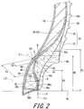
- a double-headed arrow H1 in FIG. 2 represents a height from the bead base line BL to a point P1 of the outer surface of the side portion 58 (clinch 12) of the tire 2.
- the height H1 is measured as a distance in a straight line in the radial direction.
- the point P1 is a point which is on the outer surface of the side portion 58 and at which the height H1 is 17 mm.
- An alternate long and two short dashes line L1 in FIG. 2 represents a straight line that passes through the point P1 and a point P2.
- a double-headed arrow Ts represents a thickness of the tire 2 from the point P1 to the point P2.
- the point P2 is a point which is on the inner surface of the inner liner 24 and at which the thickness Ts represents a minimum value.
- the thickness Ts represents the minimum thickness of the tire 2 at the point P1.
- An alternate long and two short dashes line L2 in FIG. 2 represents a straight line that extends in the axial direction through the radially outer end of the core 36.
- An alternate long and two short dashes line L3 represents a straight line that extends in the radial direction through the axially outer end of the core side portion 46a of the turned-up portion 46.
- a point B represents a point of intersection of the straight line L2 and the straight line L3.
- a point C is a point which is on the straight line L1 and which is distant from the point P2 by a distance that is 0.40 times the thickness Ts.
- An alternate long and two short dashes line L4 represents a straight line that passes through the point B and the point C.
- a point D represents the end of the first apex 38 in the radial direction.
- a double-headed arrow H2 represents a height from the bead base line BL to the point D.
- the height H2 represents the height of the first apex 38.
- a double-headed arrow H3 represents the height of the turned-up portion 46.
- the height H3 represents a distance from the bead base line BL to the radially outer end of the turned-up portion 46.
- the height H2 and the height H3 are each measured as a distance in a straight line in the radial direction.
- a point E represents a point of intersection of the straight line L1 and the inner surface of the second apex 40 in the axial direction.
- a double-headed arrow Te represents a distance from the point P2 to the point E.
- a region A indicated by diagonal lines in FIG. 3 is a region that is surrounded by an axially outer surface 44a of the main portion 44, the straight line L2, the straight line L1, and the straight line L4.
- the apex-layering portion 46b of each turned-up portion 46 extends radially outward through the region A.
- a portion, of the apex-layering portion 46b, which is disposed between the straight line L2 and the straight line L1, extends through the region A.
- the apex-layering portion 46b extends and is curved, to form a curved line that projects in the axially inward direction.
- FIG. 4 shows the tire 2 which is in a punctured state and with which running on a road surface G is performed.
- the center portion of the support layer 18 in the radial direction is greatly bent.
- the axially inner side portion is greatly compressed and deformed.
- the axially outer side portion is greatly expanded and deformed.
- each turned-up portion 46 is layered over the axially inner side portion of the second apex 40. Thus, damage and separation of the turned-up portions 46 are inhibited.
- each turned-up portion 46 extends through the region A.
- each turned-up portion 46 extends through the axially inward portion near the point P1.
- influence of concentrating stress is reduced.
- damage and separation of the turned-up portions 46 are inhibited.
- each turned-up portion 46 extends through the region A, whereby the turned-up portion 46 is greatly curved. The curving of the turned-up portions 46 also contributes to reduction of a vertical stiffness constant.
- the position of the point C in FIG. 2 is set to be distant by 0.40 times the thickness Ts.
- a ratio Te/Ts of a distance Te from the point P1 to the point E, relative to the thickness Ts is less than or equal to 0.40, preferably less than or equal to 0.33, and more preferably less than or equal to 0.25.
- the first apex 38 becomes small.
- stiffness is reduced.
- the ratio Te/Ts is greater than 0, more preferably not less than 0.25, and particularly preferably not less than 0.33.
- the thickness Ts is preferably greater than or equal to 10 mm, and more preferably greater than or equal to 13 mm. Meanwhile, in the tire 2 in which the thickness Ts is increased, a vertical stiffness constant is increased, and ride comfort is deteriorated. Further, in the tire 2 in which the thickness Ts is increased, the weight is increased. In these viewpoints, the thickness Ts is preferably not greater than 17 mm, and more preferably not greater than 15 mm.
- the ratio H2/Ht is preferably less than or equal to 0.40.
- the ratio H2/Ht is preferably not less than 0.15, and more preferably not less than 0.25.
- the clinches 12 are joined to the axially outer side portions of the second apexes 40.
- the second apex 40 and the clinch 12 are joined to each other.
- a complex elastic modulus E*s of the crosslinked rubber of the second apex 40, and a complex elastic modulus E*c of the crosslinked rubber of the clinch are greatly different from each other, damage originating from a boundary between the second apex 40 and the clinch 12 is likely to occur.
- the tire 2 in which a difference between the complex elastic modulus E*s and the complex elastic modulus E*c is small, is excellent in durability.
- a ratio E*c/E*s of the complex elastic modulus E*c to the complex elastic modulus E*s is preferably greater than or equal to 0.55, more preferably greater than or equal to 0.75, and particularly preferably greater than or equal to 0.90.
- the ratio E*c/E*s is preferably not greater than 1.25, more preferably not greater than 1.15, and particularly preferably not greater than 1.10.
- the first apex 38 and the second apex 40 are joined through the apex-layering portion 46b of each turned-up portion 46.
- the first apex 38, the apex-layering portion 46b, and the second apex 40 are deformed integrally.
- a complex elastic modulus E*f of the crosslinked rubber of the first apex 38 and the complex elastic modulus E*s of the crosslinked rubber of the second apex 40 are greatly different from each other, separation between each of the first apex 38 and the second apex 40, and the apex-layering portion 46b, and damage thereof are likely to occur.
- the ratio E*f/E*s is preferably greater than or equal to 0.75, more preferably greater than or equal to 0.80, and particularly preferably greater than or equal to 0.90.
- the ratio E*f/E*s is not greater than 1.28, more preferably not greater than 1.20, and particularly preferably not greater than 1.10.
- each sidewall 10 can have an increased surface area.
- the increased surface area allows increase of heat dissipation from the tire 2 into the air.
- the dimples 62 cause generation of turbulent flow around the tire 2. Due to the turbulent flow, heat dissipation from the tire 2 into the air is further increased. In the tire 2, temperature is less likely to rise. In the tire 2, damage of rubber members due to heat and separation between the rubber members due to heat are inhibited.
- the tire 2 having the dimples 62 formed therein is particularly excellent in durability.
- the support layers 18 are repeatedly deformed.
- the repeated deformation causes the temperature of the tire 2 to rise.
- the carcass 16 having the cords inhibits expansion and deformation of the support layers 18.
- the carcass 16 inhibits deformation of the support layers 18.
- the cords of the carcass 16 are preferably formed from a rayon fiber, an aramid fiber, or a polyketone fiber.
- each chafer 26 is layered over a boundary portion between the core side portion 46a and the apex-layering portion 46b of each turned-up portion 46.
- the boundary portion is likely to be damaged due to repeated deformation.
- the second apex extends so as to be tapered inward. The inner end of the second apex is disposed near the boundary portion. In the tire 2, in particular, the boundary portion is likely to be damaged due to repeated deformation.
- the chafer 26 covers the boundary portion. The chafer 26 reinforces the boundary portion.
- the dimensions of the components of the tire 2 are measured on a cross-section cut from the tire 2 as shown in FIG. 1 .
- the normal rim represents a rim that is specified according to the standard with which the tire 2 complies.
- the "standard rim” in the JATMA standard, the "Design Rim” in the TRA standard, and the “Measuring Rim” in the ETRTO standard are included in the normal rim.
- the normal internal pressure represents an internal pressure that is specified according to the standard with which the tire 2 complies.
- the complex elastic modulus is measured in compliance with the standard of "JIS K 6394".
- the measurement conditions are as follows.
- FIG. 5 shows a pneumatic tire 66 according to another embodiment of the present invention.
- the tire 66 includes an inner liner 68 instead of the inner liner 24 of the tire 2.
- the other components are the same as those of the tire 2.
- the same components as those of the tire 2 are not described.
- the components different from those of the tire 2 will be described.
- the same components as those of the tire 2 are denoted by the same reference numerals.
- the inner liner 68 includes a center portion 70 and a pair of end portions 72.
- the center portion 70 is joined to a radially outer side portion of the inner side surface of one of the support layers 18, and a radially outer side portion of the inner side surface of the other of the support layers 18.
- the paired end portions 72 are joined to radially inner side portions of the inner side surfaces of the support layers 18, to reach the chafers 26, respectively.
- the center portion 70 and the end portions 72 are discontinuously divided on the inner side surfaces of the support layers 18.
- the divided inner liner 68 contributes to reduction of the weight of the tire 2 and reduction of a vertical stiffness constant.
- the tire 66 includes the support layers 18, whereby air tightness is sufficiently exhibited also by using the inner liner 68.
- a double-headed arrow L1 represents an overlap portion in which each support layer 18 and the center portion 70 overlap each other.
- a double-headed arrow L2 represents an overlap portion in which the support layer 18 and the end portion 72 overlap each other.
- the overlap portion L1 and the overlap portion L2 are measured along the inner side surface of the support layer 18 on the cross-section shown in FIG. 5 .
- the overlap portions L1 and L2 each have a sufficient length, the inner liner 68 and the support layers 18 are integrated with each other, whereby increase of production process steps can be inhibited.
- each of the overlap portions L1 and L2 is preferably greater than or equal to 5 mm, and more preferably greater than or equal to 7 mm.
- each of the overlap portions L1 and L2 is preferably not greater than 20 mm, and more preferably not greater than 15 mm.
- the axially inner side portion in the radially center portion of each support layer 18 is greatly compressed and deformed.
- the divided inner liner 68 allows influence of the great compression and deformation to be reduced. Thus, damage and separation of the inner liner 68 is inhibited.
- the divided inner liner 68 can contribute to improvement of durability of the tire 66.
- FIG. 6 shows a part of a pneumatic tire 74 according to still another embodiment of the present invention.
- the same components as those of the tire 2 are not described.
- the components different from those of the tire 2 will be described.
- the same components as those of the tire 2 are denoted by the same reference numerals.
- the tire 74 includes a carcass 76 instead of the carcass 16.
- the other components of the tire 74 are the same as those of the tire 2.
- the carcass 76 includes a carcass ply 78.
- the carcass ply 78 is extended on and between the beads 14 on both sides.
- the carcass ply 78 is turned up around the core 36 from the inner side toward the outer side in the axial direction.
- the carcass ply 78 includes a main portion 80 and turned-up portions 82.
- Each turned-up portion 82 is layered over the radially inner side surface 36d and the axially outer side surface 36a of the core 36, and turned up from the radially inner side surface 36d to the axially outer side surface 36a.
- Each turned-up portion 82 includes a core side portion 82a, an apex-layering portion 82b, and a ply-layering portion 82c.
- the core side portion 82a is layered over the axially outer side surface 36a of the core 36.
- the apex-layering portion 82b extends continuously from the core side portion 82a in the radially outward direction.
- the ply-layering portion 82c extends continuously from the apex-layering portion 82b, and layered over the main portion 44.
- An end 84 of the ply-layering portion 82c is disposed inward of the belt 22 in the radial direction.
- the end 84 of the ply-layering portion 82c is disposed between the main portion 44 and the belt 22.
- the carcass 76 has a so-called "ultra-highly turned-up structure".
- the apex-layering portion 82b extends through the region A (see FIG. 3 ). Thus, damage and separation of the turned-up portions 82 are inhibited. Further, the apex-layering portion 82b extends through the region A, whereby the apex-layering portion 82b is greatly curved. The curving of the turned-up portions 46 also contributes to reduction of a vertical stiffness constant. While the tire 74 includes the carcass 76, the tire 74 is excellent in both durability and ride comfort.
- a pneumatic tire (run flat tire) of Example 1 having the fundamental structure shown in FIG. 1 and FIG. 2 was obtained.
- the size of the tire was 235/55R18.
- the dimples were formed as shown in FIG. 1 .
- the height H3, in the radial direction, of the turned-up portion of the carcass was 15 mm.
- the radially outer end of the turned-up portion was disposed between the first apex and the second apex.
- the radially outer end of the turned-up portion was disposed between the first apex and the chafer in the axial direction.
- Comparative example 1 was a conventional run flat tire. In the tire, the turned-up portions of the carcass ply were turned up along the axially outer side of the apexes, which is not shown. The tire had a so-called “ultra-highly turned-up structure" in which the turned-up portions and the belt overlapped each other.
- the tire of comparative example 1 had the same structure as the tire of example 1 except that dimples were not provided, and the carcass, beads, and chafers were different.
- a tire was obtained in the same manner as for example 1 except that the sidewalls had no dimples.
- the tire had the same structure as the tire of example 2 except that the tire of example 3 had the divided inner liner.
- Tires were obtained in the same manner as for example 2 except that the thickness Ts and the ratio Te/Ts were as indicated below in Table 2.
- Tires were obtained in the same manner as for example 2 except that the thickness Ts and the ratio H2/Ht were as indicated below in Table 3.
- Tires were obtained in the same manner as for example 2 except that the complex elastic modulus E*c of the clinch was as indicated below in Table 4.
- Tires were obtained in the same manner as for example 2 except that the complex elastic modulus E*s of the second apex was as indicated below in Table 5.
- Tires were obtained in the same manner as for example 2 except that the height H3, in the radial direction, of the turned-up portion of the carcass was as indicated below in Table 7.
- the end portion of the turned-up portion was layered between the carcass ply and the belt.
- a vertical stiffness constant of each tire was measured under the following conditions.
- a time required for producing the tires was measured.
- a time required for producing one tire was calculated according to the time required for producing the tires.
- Productivity was evaluated based on the reciprocal of the time required for producing one tire. The results are indicated below as indexes in Table 1 to Table 6 with a value of comparative example 1 being 100. The greater the value is, the better the productivity is.
- FIG. 1 FIG. 1
- FIG. 1 Dimple Not provided Not provided Not provided Not provided Not provided Not provided Not provided Not provided Not provided Not provided Not provided Ts (mm) 20 17 15 15 Ratio Te/Ts 0.25 0.29 0.33 0.33 Ratio H2/Ht 0.04 0.15 0.40 0.46 E*f (MPa) 11.0 11.0 11.0 11.0 E*s (MPa) 11.0 11.0 11.0 11.0 E*c (MPa) 8.1 8.1 8.1 8.1 E*r (MPa) 10.5 10.5 10.5 10.5 10.5 Ratio E*c/E*s 0.74 0.74 0.74 0.74 Ratio E*f/E*s 1.00 1.00 1.00 1.00 Vertical stiffness constant 90 92 94 95 Mass -0.28 -0.28 -0.28 -0.28 Durability 170 175 185 190 Damaged state support layer Support layer Support layer Support layer Support layer Support layer Support layer Support layer Support layer Support layer Support layer Support layer Support layer Support layer Support layer Support layer Support layer Support layer Support layer Support layer Support layer
- FIG. 1 Dimple Not provided Not provided Not provided Not provided Not provided Not provided Not provided Not provided Not provided Not provided Not provided Not provided Not provided Ts (mm) 15 15 15 15 Ratio Te/Ts 0.33 0.33 0.33 Ratio H2/Ht 0.25 0.25 0.25 0.25 0.25 E*f (MPa) 11.0 11.0 11.0 11.0 E*s (MPa) 11.0 11.0 11.0 11.0 E*c (MPa) 4.2 6.1 13.8 16.2 E*r (MPa) 10.5 10.5 10.5 10.5 10.5 Ratio E*c/E*s 0.38 0.55 1.25 1.47 Ratio E*f/E*s 1.00 1.00 1.00 1.00 Vertical stiffness constant 91 93 96 99 Mass -0.28 -0.28 -0.28 -0.28 Durability 120 170 180 120 Damaged state Interface Support layer Support layer Interface Productivity 97 97 97 97 97 97 97 97 97
- FIG. 1 Dimple Not provided Not provided Not provided Not provided Not provided Not provided Not provided Not provided Not provided Not provided Not provided Not provided Not provided Not provided Not provided Ts (mm) 15 15 15 15 15 Ratio Te/Ts 0.33 0.33 0.33 Ratio H2/Ht 0.25 0.25 0.25 0.25 E*f (MPa) 11.0 11.0 11.0 E*s (MPa) 6.0 8.6 14.7 17.9 E*c (MPa) 8.1 8.1 8.1 8.1 E*r (MPa) 10.5 10.5 10.5 10.5 10.5 Ratio E*c/E*s 1.35 0.94 0.55 0.45 Ratio E*f/E*s 1.83 1.28 0.75 0.61 Vertical stiffness constant 91 93 96 99 Mass -0.28 -0.28 -0.28 -0.28 Durability 140 170 180 160 Damaged state Interface Support layer Support layer Interface Productivity 97 97 97 97 97 97 97 97 97
- FIG. 1 FIG. 1 Dimple Not provided Not provided Not provided Not provided Not provided Not provided Not provided Not provided Not provided Not provided Not provided Not provided Not provided Not provided Not provided Not provided Not provided Not provided Not provided Not provided Not provided Ts (mm) 15 15 15 15 Ratio Te/Ts 0.33 0.33 0.33 Ratio H2/Ht 0.25 0.25 0.25 0.25 E*f (MPa) 11.0 11.0 11.0 11.0 E*s (MPa) 11.0 11.0 11.0 11.0 11.0 E*c (MPa) 8.1 8.1 8.1 8.1 E*r (MPa) 3.0 5.0 13.5 17.0 Ratio E*c/E*s 0.74 0.74 0.74 0.74 Ratio E*f/E*s 1.00 1.00 1.00 1.00 Vertical stiffness constant 88 91 96 99 Mass -0.28 -0.28 -0.28 -0.28 Durability 130 170 200 200 Damaged state Interface Support layer Support layer Support layer Support layer Productivity 97 97 97 97 97 97 97 97 97 97
- FIG. 1 FIG. 1
- the tires described above are applicable to various vehicles.
Applications Claiming Priority (2)
| Application Number | Priority Date | Filing Date | Title |
|---|---|---|---|
| JP2013237662A JP6249518B2 (ja) | 2013-11-18 | 2013-11-18 | 空気入りタイヤ |
| PCT/JP2014/078585 WO2015072322A1 (ja) | 2013-11-18 | 2014-10-28 | 空気入りタイヤ |
Publications (3)
| Publication Number | Publication Date |
|---|---|
| EP3059102A1 EP3059102A1 (en) | 2016-08-24 |
| EP3059102A4 EP3059102A4 (en) | 2017-07-12 |
| EP3059102B1 true EP3059102B1 (en) | 2019-09-18 |
Family
ID=53057261
Family Applications (1)
| Application Number | Title | Priority Date | Filing Date |
|---|---|---|---|
| EP14862256.6A Active EP3059102B1 (en) | 2013-11-18 | 2014-10-28 | Pneumatic tire |
Country Status (5)
| Country | Link |
|---|---|
| US (1) | US10040322B2 (ja) |
| EP (1) | EP3059102B1 (ja) |
| JP (1) | JP6249518B2 (ja) |
| CN (1) | CN105764712B (ja) |
| WO (1) | WO2015072322A1 (ja) |
Families Citing this family (26)
| Publication number | Priority date | Publication date | Assignee | Title |
|---|---|---|---|---|
| US9636955B2 (en) * | 2014-06-11 | 2017-05-02 | The Goodyear Tire & Rubber Company | Tire temperature predictive system and method |
| US10124630B2 (en) | 2015-01-13 | 2018-11-13 | Sumitomo Rubber Industries, Ltd. | Tire |
| DE102015209061A1 (de) * | 2015-05-18 | 2016-11-24 | Continental Reifen Deutschland Gmbh | Fahrzeugluftreifen mit Notlaufeigenschaften |
| JP6540343B2 (ja) * | 2015-08-04 | 2019-07-10 | 住友ゴム工業株式会社 | 空気入りタイヤ |
| JP6521451B2 (ja) * | 2015-09-16 | 2019-05-29 | 住友ゴム工業株式会社 | 空気入りタイヤ |
| JP6790720B2 (ja) * | 2016-10-26 | 2020-11-25 | 住友ゴム工業株式会社 | 空気入りタイヤ |
| JP6880680B2 (ja) * | 2016-12-01 | 2021-06-02 | 住友ゴム工業株式会社 | 空気入りタイヤ |
| JP6319415B1 (ja) * | 2016-12-19 | 2018-05-09 | 横浜ゴム株式会社 | ランフラットタイヤ |
| JP6801488B2 (ja) * | 2017-02-13 | 2020-12-16 | 住友ゴム工業株式会社 | 空気入りタイヤ |
| EP3677452B1 (en) * | 2017-09-12 | 2023-04-19 | Sumitomo Rubber Industries, Ltd. | Pneumatic tire |
| CN108081878A (zh) * | 2017-12-18 | 2018-05-29 | 安徽佳通乘用子午线轮胎有限公司 | 一种具有双三角胶的充气轮胎 |
| JP7069859B2 (ja) * | 2018-03-09 | 2022-05-18 | 住友ゴム工業株式会社 | ランフラットタイヤ |
| JP7063161B2 (ja) * | 2018-07-17 | 2022-05-09 | 住友ゴム工業株式会社 | 空気入りタイヤ |
| JP6594509B1 (ja) * | 2018-10-03 | 2019-10-23 | Toyo Tire株式会社 | タイヤおよびタイヤの製造方法 |
| US20210331531A1 (en) * | 2018-10-30 | 2021-10-28 | Compagnie Generate Des Etablissements Michelin | A tire having recesses in bead area |
| US11338622B2 (en) | 2018-11-16 | 2022-05-24 | The Yokohama Rubber Co., Ltd. | Run-flat tire |
| CN109849590B (zh) * | 2019-02-28 | 2020-12-04 | 安徽佳通乘用子午线轮胎有限公司 | 一种降低滚动阻力的充气轮胎 |
| CN109835124B (zh) * | 2019-02-28 | 2021-01-01 | 安徽佳通乘用子午线轮胎有限公司 | 一种降低滚阻且保持子口耐久的轮胎 |
| KR102204855B1 (ko) * | 2019-04-16 | 2021-01-20 | 한국타이어앤테크놀로지 주식회사 | 다중고무층이 적용된 비드필러를 구비한 공기입 타이어 |
| JP7151627B2 (ja) * | 2019-05-27 | 2022-10-12 | 横浜ゴム株式会社 | 空気入りタイヤ |
| JP2020203574A (ja) * | 2019-06-17 | 2020-12-24 | 株式会社ブリヂストン | ランフラットタイヤ |
| JP7401205B2 (ja) | 2019-06-19 | 2023-12-19 | Toyo Tire株式会社 | タイヤ |
| CN110341382B (zh) * | 2019-07-22 | 2021-06-01 | 三角轮胎股份有限公司 | 子午线航空轮胎 |
| CN110588252A (zh) * | 2019-10-25 | 2019-12-20 | 青岛森麒麟轮胎股份有限公司 | 一种辅助胶条,包含其的复合胎侧以及轮胎 |
| JP7352449B2 (ja) * | 2019-11-15 | 2023-09-28 | 株式会社ブリヂストン | ランフラットタイヤ |
| CN114312167B (zh) * | 2022-01-27 | 2024-03-01 | 青岛双星轮胎工业有限公司 | 一种支撑组合结构及防爆轮胎 |
Family Cites Families (26)
| Publication number | Priority date | Publication date | Assignee | Title |
|---|---|---|---|---|
| JP3667018B2 (ja) * | 1997-01-13 | 2005-07-06 | 横浜ゴム株式会社 | 空気入りタイヤ及びその製造方法 |
| US5988247A (en) * | 1997-11-17 | 1999-11-23 | Sumitomo Rubber Industries, Ltd. | Pneumatic tire with crown reinforcing rubber layer and side reinforcing rubber layers |
| DE19846854A1 (de) * | 1998-10-12 | 2000-04-20 | Dunlop Gmbh | Fahrzeugluftreifen |
| JP3312880B2 (ja) | 1999-04-16 | 2002-08-12 | 住友ゴム工業株式会社 | 安全タイヤ |
| AU2002212316A1 (en) | 2000-10-10 | 2002-04-22 | Michelin Recherche Et Technique S.A. | Tire having an outer carcass path |
| JP2002316519A (ja) * | 2001-04-25 | 2002-10-29 | Yokohama Rubber Co Ltd:The | 空気入りタイヤ |
| US6988522B2 (en) | 2002-12-12 | 2006-01-24 | The Goodyear Tire & Rubber Company | Self-supporting pneumatic tire with a partial inner liner |
| JP4263939B2 (ja) * | 2003-04-08 | 2009-05-13 | 住友ゴム工業株式会社 | 空気入りタイヤ |
| EP1479537A3 (en) * | 2003-05-13 | 2005-02-02 | Sumitomo Rubber Industries Limited | Pneumatic tire |
| DE10351587A1 (de) | 2003-11-05 | 2005-06-02 | Continental Aktiengesellschaft | Fahrzeugluftreifen |
| JP4621091B2 (ja) * | 2005-08-10 | 2011-01-26 | 住友ゴム工業株式会社 | 空気入りタイヤ |
| JP2007210363A (ja) * | 2006-02-07 | 2007-08-23 | Bridgestone Corp | 空気入りタイヤ |
| JP5006611B2 (ja) * | 2006-10-05 | 2012-08-22 | 住友ゴム工業株式会社 | 空気入りタイヤ、及びその製造方法 |
| DE102007012401A1 (de) * | 2007-03-15 | 2008-09-18 | Continental Aktiengesellschaft | Fahrzeugluftreifen mit Notlaufeigenschaften |
| JP4769228B2 (ja) * | 2007-06-01 | 2011-09-07 | 住友ゴム工業株式会社 | ランフラットタイヤ |
| JP2009078595A (ja) * | 2007-09-25 | 2009-04-16 | Sumitomo Rubber Ind Ltd | サイド補強用ゴム組成物およびランフラットタイヤ |
| JP4635040B2 (ja) * | 2007-12-06 | 2011-02-16 | 住友ゴム工業株式会社 | ランフラットタイヤ |
| JP4523634B2 (ja) * | 2007-12-17 | 2010-08-11 | 住友ゴム工業株式会社 | ランフラットタイヤ |
| JP5254126B2 (ja) * | 2008-05-16 | 2013-08-07 | 住友ゴム工業株式会社 | 空気入りタイヤ |
| US8205652B2 (en) | 2008-12-12 | 2012-06-26 | The Goodyear Tire & Rubber Company | Self-supporting pneumatic tire with optimized ply line |
| JP2011121409A (ja) * | 2009-12-08 | 2011-06-23 | Sumitomo Rubber Ind Ltd | 空気入りタイヤ |
| JP4957833B2 (ja) * | 2010-05-21 | 2012-06-20 | 横浜ゴム株式会社 | ランフラットタイヤ |
| JP5732817B2 (ja) * | 2010-11-02 | 2015-06-10 | 横浜ゴム株式会社 | 空気入りランフラットタイヤ |
| FR2970902B1 (fr) * | 2011-01-31 | 2013-02-22 | Michelin Soc Tech | Pneumatique ayant des bourrelets perfectionnes. |
| JP5457405B2 (ja) | 2011-07-29 | 2014-04-02 | 住友ゴム工業株式会社 | 空気入りタイヤ |
| JP5494601B2 (ja) | 2011-09-28 | 2014-05-21 | 横浜ゴム株式会社 | 空気入りランフラットタイヤ |
-
2013
- 2013-11-18 JP JP2013237662A patent/JP6249518B2/ja active Active
-
2014
- 2014-10-28 WO PCT/JP2014/078585 patent/WO2015072322A1/ja active Application Filing
- 2014-10-28 EP EP14862256.6A patent/EP3059102B1/en active Active
- 2014-10-28 US US15/025,043 patent/US10040322B2/en active Active
- 2014-10-28 CN CN201480062630.XA patent/CN105764712B/zh active Active
Also Published As
| Publication number | Publication date |
|---|---|
| US10040322B2 (en) | 2018-08-07 |
| CN105764712A (zh) | 2016-07-13 |
| EP3059102A4 (en) | 2017-07-12 |
| WO2015072322A1 (ja) | 2015-05-21 |
| EP3059102A1 (en) | 2016-08-24 |
| US20160236521A1 (en) | 2016-08-18 |
| CN105764712B (zh) | 2018-06-19 |
| JP6249518B2 (ja) | 2017-12-20 |
| JP2015098198A (ja) | 2015-05-28 |
Similar Documents
| Publication | Publication Date | Title |
|---|---|---|
| EP3059102B1 (en) | Pneumatic tire | |
| JP6299217B2 (ja) | 空気入りタイヤ | |
| US10589577B2 (en) | Heavy-duty pneumatic tire | |
| EP3281805B1 (en) | Pneumatic tire | |
| JP4973810B1 (ja) | 空気入りタイヤ | |
| US9272582B2 (en) | Pneumatic tire | |
| EP2853419B1 (en) | Pneumatic tire | |
| US10821785B2 (en) | Pneumatic tire | |
| CN110758023A (zh) | 充气轮胎 | |
| EP3357715B1 (en) | Pneumatic tire | |
| JP2017056815A (ja) | 空気入りタイヤ | |
| EP3135506B1 (en) | Pneumatic tire | |
| EP3235664B1 (en) | Pneumatic tire | |
| EP3093161B1 (en) | Pneumatic tire | |
| US11198333B2 (en) | Tire for two-wheeled automotive vehicle | |
| EP3202599A1 (en) | Pneumatic tire | |
| JP5772254B2 (ja) | 空気入りタイヤ | |
| US20240051350A1 (en) | Tire | |
| EP3189988B1 (en) | Pneumatic tire | |
| JP2018167680A (ja) | 空気入りタイヤ | |
| JP2012017074A (ja) | 空気入りラジアルタイヤ |
Legal Events
| Date | Code | Title | Description |
|---|---|---|---|
| PUAI | Public reference made under article 153(3) epc to a published international application that has entered the european phase |
Free format text: ORIGINAL CODE: 0009012 |
|
| 17P | Request for examination filed |
Effective date: 20160518 |
|
| AK | Designated contracting states |
Kind code of ref document: A1 Designated state(s): AL AT BE BG CH CY CZ DE DK EE ES FI FR GB GR HR HU IE IS IT LI LT LU LV MC MK MT NL NO PL PT RO RS SE SI SK SM TR |
|
| AX | Request for extension of the european patent |
Extension state: BA ME |
|
| DAX | Request for extension of the european patent (deleted) | ||
| A4 | Supplementary search report drawn up and despatched |
Effective date: 20170613 |
|
| RIC1 | Information provided on ipc code assigned before grant |
Ipc: B60C 13/00 20060101ALI20170607BHEP Ipc: B60C 5/14 20060101ALI20170607BHEP Ipc: B60C 15/00 20060101ALI20170607BHEP Ipc: B60C 7/12 20060101ALI20170607BHEP Ipc: B60C 15/06 20060101ALI20170607BHEP Ipc: B60C 9/02 20060101ALI20170607BHEP Ipc: B60C 17/00 20060101AFI20170607BHEP Ipc: B60C 1/00 20060101ALI20170607BHEP Ipc: B60C 11/00 20060101ALI20170607BHEP Ipc: B60C 15/04 20060101ALI20170607BHEP |
|
| GRAP | Despatch of communication of intention to grant a patent |
Free format text: ORIGINAL CODE: EPIDOSNIGR1 |
|
| STAA | Information on the status of an ep patent application or granted ep patent |
Free format text: STATUS: GRANT OF PATENT IS INTENDED |
|
| INTG | Intention to grant announced |
Effective date: 20190327 |
|
| GRAS | Grant fee paid |
Free format text: ORIGINAL CODE: EPIDOSNIGR3 |
|
| GRAA | (expected) grant |
Free format text: ORIGINAL CODE: 0009210 |
|
| STAA | Information on the status of an ep patent application or granted ep patent |
Free format text: STATUS: THE PATENT HAS BEEN GRANTED |
|
| AK | Designated contracting states |
Kind code of ref document: B1 Designated state(s): AL AT BE BG CH CY CZ DE DK EE ES FI FR GB GR HR HU IE IS IT LI LT LU LV MC MK MT NL NO PL PT RO RS SE SI SK SM TR |
|
| REG | Reference to a national code |
Ref country code: GB Ref legal event code: FG4D |
|
| REG | Reference to a national code |
Ref country code: CH Ref legal event code: EP |
|
| REG | Reference to a national code |
Ref country code: DE Ref legal event code: R096 Ref document number: 602014054026 Country of ref document: DE |
|
| REG | Reference to a national code |
Ref country code: AT Ref legal event code: REF Ref document number: 1180837 Country of ref document: AT Kind code of ref document: T Effective date: 20191015 |
|
| REG | Reference to a national code |
Ref country code: IE Ref legal event code: FG4D |
|
| REG | Reference to a national code |
Ref country code: NL Ref legal event code: MP Effective date: 20190918 |
|
| PG25 | Lapsed in a contracting state [announced via postgrant information from national office to epo] |
Ref country code: HR Free format text: LAPSE BECAUSE OF FAILURE TO SUBMIT A TRANSLATION OF THE DESCRIPTION OR TO PAY THE FEE WITHIN THE PRESCRIBED TIME-LIMIT Effective date: 20190918 Ref country code: LT Free format text: LAPSE BECAUSE OF FAILURE TO SUBMIT A TRANSLATION OF THE DESCRIPTION OR TO PAY THE FEE WITHIN THE PRESCRIBED TIME-LIMIT Effective date: 20190918 Ref country code: NO Free format text: LAPSE BECAUSE OF FAILURE TO SUBMIT A TRANSLATION OF THE DESCRIPTION OR TO PAY THE FEE WITHIN THE PRESCRIBED TIME-LIMIT Effective date: 20191218 Ref country code: BG Free format text: LAPSE BECAUSE OF FAILURE TO SUBMIT A TRANSLATION OF THE DESCRIPTION OR TO PAY THE FEE WITHIN THE PRESCRIBED TIME-LIMIT Effective date: 20191218 Ref country code: FI Free format text: LAPSE BECAUSE OF FAILURE TO SUBMIT A TRANSLATION OF THE DESCRIPTION OR TO PAY THE FEE WITHIN THE PRESCRIBED TIME-LIMIT Effective date: 20190918 Ref country code: SE Free format text: LAPSE BECAUSE OF FAILURE TO SUBMIT A TRANSLATION OF THE DESCRIPTION OR TO PAY THE FEE WITHIN THE PRESCRIBED TIME-LIMIT Effective date: 20190918 |
|
| REG | Reference to a national code |
Ref country code: LT Ref legal event code: MG4D |
|
| PG25 | Lapsed in a contracting state [announced via postgrant information from national office to epo] |
Ref country code: RS Free format text: LAPSE BECAUSE OF FAILURE TO SUBMIT A TRANSLATION OF THE DESCRIPTION OR TO PAY THE FEE WITHIN THE PRESCRIBED TIME-LIMIT Effective date: 20190918 Ref country code: LV Free format text: LAPSE BECAUSE OF FAILURE TO SUBMIT A TRANSLATION OF THE DESCRIPTION OR TO PAY THE FEE WITHIN THE PRESCRIBED TIME-LIMIT Effective date: 20190918 Ref country code: GR Free format text: LAPSE BECAUSE OF FAILURE TO SUBMIT A TRANSLATION OF THE DESCRIPTION OR TO PAY THE FEE WITHIN THE PRESCRIBED TIME-LIMIT Effective date: 20191219 Ref country code: AL Free format text: LAPSE BECAUSE OF FAILURE TO SUBMIT A TRANSLATION OF THE DESCRIPTION OR TO PAY THE FEE WITHIN THE PRESCRIBED TIME-LIMIT Effective date: 20190918 |
|
| REG | Reference to a national code |
Ref country code: AT Ref legal event code: MK05 Ref document number: 1180837 Country of ref document: AT Kind code of ref document: T Effective date: 20190918 |
|
| PG25 | Lapsed in a contracting state [announced via postgrant information from national office to epo] |
Ref country code: NL Free format text: LAPSE BECAUSE OF FAILURE TO SUBMIT A TRANSLATION OF THE DESCRIPTION OR TO PAY THE FEE WITHIN THE PRESCRIBED TIME-LIMIT Effective date: 20190918 Ref country code: AT Free format text: LAPSE BECAUSE OF FAILURE TO SUBMIT A TRANSLATION OF THE DESCRIPTION OR TO PAY THE FEE WITHIN THE PRESCRIBED TIME-LIMIT Effective date: 20190918 Ref country code: EE Free format text: LAPSE BECAUSE OF FAILURE TO SUBMIT A TRANSLATION OF THE DESCRIPTION OR TO PAY THE FEE WITHIN THE PRESCRIBED TIME-LIMIT Effective date: 20190918 Ref country code: PT Free format text: LAPSE BECAUSE OF FAILURE TO SUBMIT A TRANSLATION OF THE DESCRIPTION OR TO PAY THE FEE WITHIN THE PRESCRIBED TIME-LIMIT Effective date: 20200120 Ref country code: RO Free format text: LAPSE BECAUSE OF FAILURE TO SUBMIT A TRANSLATION OF THE DESCRIPTION OR TO PAY THE FEE WITHIN THE PRESCRIBED TIME-LIMIT Effective date: 20190918 Ref country code: IT Free format text: LAPSE BECAUSE OF FAILURE TO SUBMIT A TRANSLATION OF THE DESCRIPTION OR TO PAY THE FEE WITHIN THE PRESCRIBED TIME-LIMIT Effective date: 20190918 Ref country code: PL Free format text: LAPSE BECAUSE OF FAILURE TO SUBMIT A TRANSLATION OF THE DESCRIPTION OR TO PAY THE FEE WITHIN THE PRESCRIBED TIME-LIMIT Effective date: 20190918 Ref country code: ES Free format text: LAPSE BECAUSE OF FAILURE TO SUBMIT A TRANSLATION OF THE DESCRIPTION OR TO PAY THE FEE WITHIN THE PRESCRIBED TIME-LIMIT Effective date: 20190918 |
|
| PG25 | Lapsed in a contracting state [announced via postgrant information from national office to epo] |
Ref country code: SK Free format text: LAPSE BECAUSE OF FAILURE TO SUBMIT A TRANSLATION OF THE DESCRIPTION OR TO PAY THE FEE WITHIN THE PRESCRIBED TIME-LIMIT Effective date: 20190918 Ref country code: CZ Free format text: LAPSE BECAUSE OF FAILURE TO SUBMIT A TRANSLATION OF THE DESCRIPTION OR TO PAY THE FEE WITHIN THE PRESCRIBED TIME-LIMIT Effective date: 20190918 Ref country code: IS Free format text: LAPSE BECAUSE OF FAILURE TO SUBMIT A TRANSLATION OF THE DESCRIPTION OR TO PAY THE FEE WITHIN THE PRESCRIBED TIME-LIMIT Effective date: 20200224 Ref country code: SM Free format text: LAPSE BECAUSE OF FAILURE TO SUBMIT A TRANSLATION OF THE DESCRIPTION OR TO PAY THE FEE WITHIN THE PRESCRIBED TIME-LIMIT Effective date: 20190918 |
|
| REG | Reference to a national code |
Ref country code: CH Ref legal event code: PL |
|
| REG | Reference to a national code |
Ref country code: DE Ref legal event code: R097 Ref document number: 602014054026 Country of ref document: DE |
|
| PLBE | No opposition filed within time limit |
Free format text: ORIGINAL CODE: 0009261 |
|
| STAA | Information on the status of an ep patent application or granted ep patent |
Free format text: STATUS: NO OPPOSITION FILED WITHIN TIME LIMIT |
|
| PG2D | Information on lapse in contracting state deleted |
Ref country code: IS |
|
| PG25 | Lapsed in a contracting state [announced via postgrant information from national office to epo] |
Ref country code: CH Free format text: LAPSE BECAUSE OF NON-PAYMENT OF DUE FEES Effective date: 20191031 Ref country code: DK Free format text: LAPSE BECAUSE OF FAILURE TO SUBMIT A TRANSLATION OF THE DESCRIPTION OR TO PAY THE FEE WITHIN THE PRESCRIBED TIME-LIMIT Effective date: 20190918 Ref country code: LU Free format text: LAPSE BECAUSE OF NON-PAYMENT OF DUE FEES Effective date: 20191028 Ref country code: LI Free format text: LAPSE BECAUSE OF NON-PAYMENT OF DUE FEES Effective date: 20191031 Ref country code: IS Free format text: LAPSE BECAUSE OF FAILURE TO SUBMIT A TRANSLATION OF THE DESCRIPTION OR TO PAY THE FEE WITHIN THE PRESCRIBED TIME-LIMIT Effective date: 20200119 |
|
| REG | Reference to a national code |
Ref country code: BE Ref legal event code: MM Effective date: 20191031 |
|
| 26N | No opposition filed |
Effective date: 20200619 |
|
| PG25 | Lapsed in a contracting state [announced via postgrant information from national office to epo] |
Ref country code: SI Free format text: LAPSE BECAUSE OF FAILURE TO SUBMIT A TRANSLATION OF THE DESCRIPTION OR TO PAY THE FEE WITHIN THE PRESCRIBED TIME-LIMIT Effective date: 20190918 Ref country code: MC Free format text: LAPSE BECAUSE OF FAILURE TO SUBMIT A TRANSLATION OF THE DESCRIPTION OR TO PAY THE FEE WITHIN THE PRESCRIBED TIME-LIMIT Effective date: 20190918 Ref country code: BE Free format text: LAPSE BECAUSE OF NON-PAYMENT OF DUE FEES Effective date: 20191031 |
|
| GBPC | Gb: european patent ceased through non-payment of renewal fee |
Effective date: 20191218 |
|
| PG25 | Lapsed in a contracting state [announced via postgrant information from national office to epo] |
Ref country code: IE Free format text: LAPSE BECAUSE OF NON-PAYMENT OF DUE FEES Effective date: 20191028 Ref country code: GB Free format text: LAPSE BECAUSE OF NON-PAYMENT OF DUE FEES Effective date: 20191218 |
|
| PG25 | Lapsed in a contracting state [announced via postgrant information from national office to epo] |
Ref country code: CY Free format text: LAPSE BECAUSE OF FAILURE TO SUBMIT A TRANSLATION OF THE DESCRIPTION OR TO PAY THE FEE WITHIN THE PRESCRIBED TIME-LIMIT Effective date: 20190918 |
|
| PG25 | Lapsed in a contracting state [announced via postgrant information from national office to epo] |
Ref country code: HU Free format text: LAPSE BECAUSE OF FAILURE TO SUBMIT A TRANSLATION OF THE DESCRIPTION OR TO PAY THE FEE WITHIN THE PRESCRIBED TIME-LIMIT; INVALID AB INITIO Effective date: 20141028 Ref country code: MT Free format text: LAPSE BECAUSE OF FAILURE TO SUBMIT A TRANSLATION OF THE DESCRIPTION OR TO PAY THE FEE WITHIN THE PRESCRIBED TIME-LIMIT Effective date: 20190918 |
|
| PG25 | Lapsed in a contracting state [announced via postgrant information from national office to epo] |
Ref country code: TR Free format text: LAPSE BECAUSE OF FAILURE TO SUBMIT A TRANSLATION OF THE DESCRIPTION OR TO PAY THE FEE WITHIN THE PRESCRIBED TIME-LIMIT Effective date: 20190918 |
|
| PG25 | Lapsed in a contracting state [announced via postgrant information from national office to epo] |
Ref country code: MK Free format text: LAPSE BECAUSE OF FAILURE TO SUBMIT A TRANSLATION OF THE DESCRIPTION OR TO PAY THE FEE WITHIN THE PRESCRIBED TIME-LIMIT Effective date: 20190918 |
|
| PGFP | Annual fee paid to national office [announced via postgrant information from national office to epo] |
Ref country code: FR Payment date: 20230911 Year of fee payment: 10 |
|
| PGFP | Annual fee paid to national office [announced via postgrant information from national office to epo] |
Ref country code: DE Payment date: 20230906 Year of fee payment: 10 |