EP3046786B1 - Heizungs-, lüftungs- und/oder klimaanlage für den passagierraum eines kraftfahrzeugs - Google Patents
Heizungs-, lüftungs- und/oder klimaanlage für den passagierraum eines kraftfahrzeugs Download PDFInfo
- Publication number
- EP3046786B1 EP3046786B1 EP14761840.9A EP14761840A EP3046786B1 EP 3046786 B1 EP3046786 B1 EP 3046786B1 EP 14761840 A EP14761840 A EP 14761840A EP 3046786 B1 EP3046786 B1 EP 3046786B1
- Authority
- EP
- European Patent Office
- Prior art keywords
- air
- air distribution
- volute
- installation according
- passenger compartment
- Prior art date
- Legal status (The legal status is an assumption and is not a legal conclusion. Google has not performed a legal analysis and makes no representation as to the accuracy of the status listed.)
- Active
Links
- 238000009434 installation Methods 0.000 title claims description 52
- 238000010438 heat treatment Methods 0.000 title claims description 31
- 238000009423 ventilation Methods 0.000 title claims description 21
- 238000004378 air conditioning Methods 0.000 title claims description 7
- 230000002093 peripheral effect Effects 0.000 claims description 23
- 238000005192 partition Methods 0.000 claims description 14
- 238000007789 sealing Methods 0.000 claims description 10
- 239000011343 solid material Substances 0.000 claims description 3
- 238000005273 aeration Methods 0.000 claims 2
- 238000004064 recycling Methods 0.000 description 17
- 238000000926 separation method Methods 0.000 description 6
- 230000004907 flux Effects 0.000 description 5
- 239000000203 mixture Substances 0.000 description 5
- 238000010257 thawing Methods 0.000 description 4
- 238000011144 upstream manufacturing Methods 0.000 description 3
- 238000001816 cooling Methods 0.000 description 2
- 230000003134 recirculating effect Effects 0.000 description 2
- XLYOFNOQVPJJNP-UHFFFAOYSA-N water Substances O XLYOFNOQVPJJNP-UHFFFAOYSA-N 0.000 description 2
- 230000000295 complement effect Effects 0.000 description 1
Images

Classifications
-
- B—PERFORMING OPERATIONS; TRANSPORTING
- B60—VEHICLES IN GENERAL
- B60H—ARRANGEMENTS OF HEATING, COOLING, VENTILATING OR OTHER AIR-TREATING DEVICES SPECIALLY ADAPTED FOR PASSENGER OR GOODS SPACES OF VEHICLES
- B60H1/00—Heating, cooling or ventilating [HVAC] devices
- B60H1/00007—Combined heating, ventilating, or cooling devices
- B60H1/00021—Air flow details of HVAC devices
- B60H1/00064—Air flow details of HVAC devices for sending air streams of different temperatures into the passenger compartment
-
- B—PERFORMING OPERATIONS; TRANSPORTING
- B60—VEHICLES IN GENERAL
- B60H—ARRANGEMENTS OF HEATING, COOLING, VENTILATING OR OTHER AIR-TREATING DEVICES SPECIALLY ADAPTED FOR PASSENGER OR GOODS SPACES OF VEHICLES
- B60H1/00—Heating, cooling or ventilating [HVAC] devices
- B60H1/00357—Air-conditioning arrangements specially adapted for particular vehicles
- B60H1/00385—Air-conditioning arrangements specially adapted for particular vehicles for vehicles having an electrical drive, e.g. hybrid or fuel cell
- B60H1/00392—Air-conditioning arrangements specially adapted for particular vehicles for vehicles having an electrical drive, e.g. hybrid or fuel cell for electric vehicles having only electric drive means
-
- B—PERFORMING OPERATIONS; TRANSPORTING
- B60—VEHICLES IN GENERAL
- B60H—ARRANGEMENTS OF HEATING, COOLING, VENTILATING OR OTHER AIR-TREATING DEVICES SPECIALLY ADAPTED FOR PASSENGER OR GOODS SPACES OF VEHICLES
- B60H1/00—Heating, cooling or ventilating [HVAC] devices
- B60H1/00457—Ventilation unit, e.g. combined with a radiator
- B60H1/00471—The ventilator being of the radial type, i.e. with radial expulsion of the air
-
- B—PERFORMING OPERATIONS; TRANSPORTING
- B60—VEHICLES IN GENERAL
- B60H—ARRANGEMENTS OF HEATING, COOLING, VENTILATING OR OTHER AIR-TREATING DEVICES SPECIALLY ADAPTED FOR PASSENGER OR GOODS SPACES OF VEHICLES
- B60H1/00—Heating, cooling or ventilating [HVAC] devices
- B60H1/00507—Details, e.g. mounting arrangements, desaeration devices
- B60H1/00557—Details of ducts or cables
- B60H1/00564—Details of ducts or cables of air ducts
-
- B—PERFORMING OPERATIONS; TRANSPORTING
- B60—VEHICLES IN GENERAL
- B60H—ARRANGEMENTS OF HEATING, COOLING, VENTILATING OR OTHER AIR-TREATING DEVICES SPECIALLY ADAPTED FOR PASSENGER OR GOODS SPACES OF VEHICLES
- B60H1/00—Heating, cooling or ventilating [HVAC] devices
- B60H1/00642—Control systems or circuits; Control members or indication devices for heating, cooling or ventilating devices
- B60H1/00664—Construction or arrangement of damper doors
- B60H1/00671—Damper doors moved by rotation; Grilles
- B60H1/00678—Damper doors moved by rotation; Grilles the axis of rotation being in the door plane, e.g. butterfly doors
-
- B—PERFORMING OPERATIONS; TRANSPORTING
- B60—VEHICLES IN GENERAL
- B60H—ARRANGEMENTS OF HEATING, COOLING, VENTILATING OR OTHER AIR-TREATING DEVICES SPECIALLY ADAPTED FOR PASSENGER OR GOODS SPACES OF VEHICLES
- B60H1/00—Heating, cooling or ventilating [HVAC] devices
- B60H1/22—Heating, cooling or ventilating [HVAC] devices the heat being derived otherwise than from the propulsion plant
- B60H1/2215—Heating, cooling or ventilating [HVAC] devices the heat being derived otherwise than from the propulsion plant the heat being derived from electric heaters
- B60H1/2221—Heating, cooling or ventilating [HVAC] devices the heat being derived otherwise than from the propulsion plant the heat being derived from electric heaters arrangements of electric heaters for heating an intermediate liquid
-
- B—PERFORMING OPERATIONS; TRANSPORTING
- B60—VEHICLES IN GENERAL
- B60H—ARRANGEMENTS OF HEATING, COOLING, VENTILATING OR OTHER AIR-TREATING DEVICES SPECIALLY ADAPTED FOR PASSENGER OR GOODS SPACES OF VEHICLES
- B60H1/00—Heating, cooling or ventilating [HVAC] devices
- B60H1/00007—Combined heating, ventilating, or cooling devices
- B60H1/00021—Air flow details of HVAC devices
- B60H2001/00078—Assembling, manufacturing or layout details
- B60H2001/00085—Assembling, manufacturing or layout details of air intake
-
- B—PERFORMING OPERATIONS; TRANSPORTING
- B60—VEHICLES IN GENERAL
- B60H—ARRANGEMENTS OF HEATING, COOLING, VENTILATING OR OTHER AIR-TREATING DEVICES SPECIALLY ADAPTED FOR PASSENGER OR GOODS SPACES OF VEHICLES
- B60H1/00—Heating, cooling or ventilating [HVAC] devices
- B60H1/00007—Combined heating, ventilating, or cooling devices
- B60H1/00021—Air flow details of HVAC devices
- B60H2001/00078—Assembling, manufacturing or layout details
- B60H2001/00092—Assembling, manufacturing or layout details of air deflecting or air directing means inside the device
-
- B—PERFORMING OPERATIONS; TRANSPORTING
- B60—VEHICLES IN GENERAL
- B60H—ARRANGEMENTS OF HEATING, COOLING, VENTILATING OR OTHER AIR-TREATING DEVICES SPECIALLY ADAPTED FOR PASSENGER OR GOODS SPACES OF VEHICLES
- B60H1/00—Heating, cooling or ventilating [HVAC] devices
- B60H1/00007—Combined heating, ventilating, or cooling devices
- B60H1/00021—Air flow details of HVAC devices
- B60H2001/00114—Heating or cooling details
- B60H2001/00135—Deviding walls for separate air flows
Definitions
- the present invention relates to a heating, ventilation and / or air conditioning installation for a passenger compartment of a motor vehicle allowing the control of the air flow temperature in one or more zones of the passenger compartment of a motor vehicle.
- the document DE 199 54 308 A1 describes such an installation.
- a motor vehicle is commonly equipped with a heating, ventilation and / or air conditioning installation which is intended to regulate the aerothermal parameters of the air distributed in the passenger compartment, in particular the temperature of a flow of air delivered. by installation inside the passenger compartment.
- the installation comprises a housing delimited by partitions through which are formed openings, including at least one air inlet and at least one air distribution mouth.
- the box generally houses a motor-fan group also called a blower to circulate the air flow from the air inlet to the air distribution mouth.
- the housing also houses heat treatment means for heating and / or cooling the air flow prior to its distribution inside the passenger compartment through the air distribution mouth.
- the heat treatment means may include an evaporator which is intended to cool the air passing through it, and a radiator, possibly associated with an additional radiator, which is intended to heat the air passing through it.
- the installation may also include several flaps to control the passage of air through distribution outlets corresponding to ventilation or ventilation outlets opening in the passenger compartment of the vehicle, or even to a defrost outlet / demisting in particular of the vehicle windshield.
- the air circulating in such an installation can be a flow of outside air, or the air flow coming from the passenger compartment circulating again in the installation, this is called a recirculated or recirculating air flow. , or a mixture both.
- a mixing flap can distribute the proportion of outside air and the proportion of recycled air.
- drier outside air than recirculated air should preferably be blown into the passenger compartment.
- two-level installations that is to say comprising two air distribution channels housing the heat treatment means of a conventional installation to ensure thermal comfort in the passenger compartment, and each level can be supplied by an air flow of the same origin or of separate origin.
- the supply of external air flow and / or of recycled air flow can be selected as required, for example by sending a flow of external air to the windshield to respond to the problem of fogging. vehicle windows, in particular the windshield, and by sending a flow of recycled air to the foot ventilation outlets in the passenger compartment for faster heating.
- Such a system is restrictive because it requires bypass ducts to separate the air flows and distribute, for example, a recirculated air flow in the second level forming for example a lower part of the installation while a flow of fresh outside air must be distributed in the first level in this case forming the upper part of the installation.
- the presence of the bypass conduits implies a larger bulk of the installation in the vehicle.
- such a system has one or more flaps to distribute the air flows and is therefore more complex.
- the invention therefore aims to provide an improved installation to at least partially resolve the drawbacks of the prior art.
- This solution makes it possible to set up a suction dedicated to recycling at the level of the second air intake channel.
- the invention thus proposes to distribute to the air outlets, air flows which may, depending on the case, have a distinct origin or a common origin. More specifically, an air flow coming from the first air intake channel which can be supplied either by an external air flow or by a recycled air flow, or even a mixture of the two, can be distributed to one or more first air outlets at the first air distribution channel.
- an air flow of origin separate from the first air flow and totally recycled can be directed to a second air outlet separated from the first outlets air, at the second air distribution channel.
- the permanent recycling of part of the air flow distributed in the passenger compartment makes it possible to meet a need for rapid heating of the air while, for reasons of demisting, for example a flow of fresh outside air or mixed with recycled air can be sent to the windshield.
- the motor-fan unit comprises a wheel having a bowl made of solid material and extending between the first part and the second part of the motor-fan group.
- the bowl makes it possible to divide the motor-fan group in two and thus ensures separation of the air flows from the first air intake channel and the second air intake channel from the origin of the air flows. air.
- the motor-fan unit comprises first blades extending from an external peripheral edge of the bowl towards a first external peripheral edge of the wheel and second blades extending opposite to the first blades from the outer peripheral edge of the bowl to a second outer peripheral edge of the wheel.
- the motor-fan unit has two separate opposite suction regions.
- the second suction region is dedicated to specific recycling.
- This volute is separated into two volumes thus defining an upper part and a lower part.
- the upper part communicates with the first air intake channel corresponding to a conventional air inlet which can be supplied by outside air and / or recycled air, which passes through the volute then is introduced into the first air distribution channel to the outlets, for example defrost and head ventilation in the passenger compartment.
- a conventional air inlet which can be supplied by outside air and / or recycled air, which passes through the volute then is introduced into the first air distribution channel to the outlets, for example defrost and head ventilation in the passenger compartment.
- the lower part communicates with the second air intake channel corresponding to the specific recycling in order to introduce a flow of air which is always recycled into the second air distribution channel up to an outlet, for example for aerating the feet in the cabin.
- the sealing means may comprise a wall arranged between the two volumes of the volute and a means for holding the wall in the volute.
- the wall allows you to easily partition the scroll.
- the holding means is made in one piece with the wall.
- the sealing means may comprise a substantially cylindrical peripheral skirt forming a support for the wall and received in a housing complementary to the volute.
- said installation comprises at least one flow shutter arranged in the second air intake channel so as to adjust the air flow of the recirculated air flow.
- the flow shutter dedicated to permanent recycling makes it possible to manage the flow of the recirculated air flow, for example as a function of vehicle parameters such as the speed of the vehicle.
- the installation comprises a partition wall arranged between the first air distribution channel and the second air distribution channel.
- the installation comprises means for heat treatment of air flows arranged in the first air distribution channel and in the second air distribution channel. Said heat treatment means are common to the two air distribution channels.
- Said heat treatment means may respectively comprise an internal partition for separating the air flows passing through the first air distribution channel and the second air distribution channel.
- the partition between the two distribution channels and the internal partitions at the level of the heat treatment means allowing the separation between the two air flows until delivery into the respective air outlets.
- a switching flap can be arranged to put the two air distribution channels in communication, for example to send a larger quantity of air to one of the air outlets.
- said at least one first outlet is a defrost outlet oriented towards the windshield of said vehicle or a passenger head ventilation outlet in the passenger compartment of said vehicle, and the second outlet is an outlet ventilation oriented towards the feet of passengers in the passenger compartment.
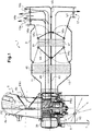
- the figure 1 is a schematic view of a heating, ventilation and / or air conditioning installation 1 intended to equip a motor vehicle to regulate the aerothermal parameters of the air flow distributed in one or more zones of the passenger compartment of the vehicle.
- the housing 3 comprises a first intake mouth 4a for the introduction of an external air flow FE coming from outside the vehicle into the first air intake channel 5 allowing its circulation in the internal volume delimited through the housing 3.
- the box 3 also includes a second inlet mouth 4b for the introduction of a first flow of recycled air FR1 coming from the passenger compartment of the vehicle and circulating again in the internal volume delimited by the box 3.
- the air inlets can be reversed, that is to say that the recycled air FR1 can be applied to the inlet 4a and the outside air FE to the inlet 4b.
- the first air intake channel 5 can be supplied both by the external air flow FE or the first recycled air flow FR1 as well as by a mixture of the two external air flows FE and recycled FR1.
- the outside air flow FE and the first recycling air flow FR1 can be mixed with each other in the first air intake channel 5.
- an air mixing device such as a first mixing flap V1 pivotally mounted allows the outside air flow FE and the first recycled air flow FR1 to be distributed in the desired proportion. first air intake channel 5.
- the mixing flap V1 is movable between two extreme closing positions. In a first closed position called the recycling position, the mixing flap V1 prohibits the passage of the outside air flow FE towards the first air intake channel 5 while allowing a passage of the first recycled air flow FR1 towards the first air intake channel 5. In the second closed position called the external position, the mixing flap V1 prevents the passage of the flow of recycled air FR1 to the first air intake channel 5 while authorizing a passage of the external air flow FE towards the first air intake channel 5.
- the mixing flap V1 is arranged in such a way that it calibrates, in intermediate positions, the proportion of the flow of outside air FE and the first flow of recycled air FR1 entering the first air intake channel 5 .
- the stroke of the first flap V1 is shown diagrammatically by dotted lines starting from the end of the first flap V1 on the figure 1 .
- the second air intake channel 7 is reserved for the introduction of a second flow of recycled air FR2 coming from the passenger compartment and circulating again in the installation 1.
- Different positions of the second flap V2 for managing the flow rate of the second flow of recycled air FR2 are illustrated by way of example on the figure 1 .
- the flow management can be done by way of example depending on the speed of the vehicle.
- the flow rate of this specific recycling can be between 10% and 50% of the flow rate of the aspirated air flow coming from the first air intake channel 5.
- the flow shutter V2 must not be completely closed because a certain amount of air must be allowed to cool the engine.
- the motor-fan unit also called a blower 9 is arranged so as to circulate an air flow from the first air intake channel 5 or from the second air intake channel 7 in the installation 1 and subsequently to the air outlets 15a, 15b and 17, for example a defrosting / defogging outlet 15a, a head ventilation outlet 15b and a foot ventilation mouth 17.
- the air delivered through the defrosting / defogging mouth 15a makes it possible to supply one or more nozzles arranged at the level of the vehicle windshield.
- the head ventilation outlet 15b makes it possible to ventilate an upper zone of the passenger compartment while the foot ventilation outlet 17 makes it possible to ventilate a lower zone of the passenger compartment.
- the blower 9 is arranged downstream of the first intake channel 5 in the direction of flow of the outside air flow FE and the first recycled air flow FR1 so as to circulate an air flow from the first air intake channel 5 in installation 1, more precisely in the first air distribution channel 11, and subsequently towards the outlets 15a and 15b.
- the blower 9 is also arranged downstream of the second intake channel 7 in the direction of flow of the second recycled air flow FR2 so as to circulate an air flow from the second air intake channel 7 in installation 1, more precisely in the second air distribution channel 13, and subsequently towards outlet 17.
- the blower 9 makes it possible to introduce into the first air distribution channel 11 either outside air FE taken from outside the passenger compartment, or re-circulating air taken from inside the passenger compartment says first recirculated air flow FR1, or a mixture of the two, and in the second air distribution channel 13 a permanent recirculated air stream taken from inside the passenger compartment says second air flow recycled FR2.
- the lower part 9b is therefore dedicated to permanent recycling.
- This lower part 9b for permanent recycling can be between 10% and 35% in height of the blower 9.
- the blower 9 comprises a fan and a motor 21 capable of driving the fan in rotation around a drive axis I.
- the fan comprises a wheel 23.
- the electric motor 21 is capable of driving the wheel 23 in rotation so as to set in motion an air flow in the installation 1.
- the wheel 23 is cylindrical.
- the wheel 23 better visible on the figure 3 presents a bowl 25.
- the bowl 25 is made of solid material, so as to form a sealed separation between the upper part 9a of the blower and the lower part 9b of the blower 9. This separation produced by the bowl 25 prevents the flow of air from the first channel air intake 5 to be introduced into the second distribution channel 13 through the lower part 9b of the blower 9, and conversely prevents the air flow from the second air intake channel 7 from being introduced in the first distribution channel 11 through the upper part 9a of the blower 9.
- the bowl 25 comprises substantially in its middle a hub 27 whose function is to mechanically connect the wheel 23 to a drive shaft 29.
- the bowl 25 also has an external peripheral edge 30.
- the wheel 23 also has blades or fins 31, 33 on its periphery.
- first blades 31 extend from the outer peripheral edge 30 of the bowl 25 towards a first outer peripheral edge 35 of the wheel 23 and second blades 33 extend from the outer peripheral edge 30 of the bowl 25 opposite the first blades 31 towards a second external peripheral border 37.
- the blower 9 therefore has a first open end face A delimited by the first external peripheral border 35 and a second open end face B opposite to the first end face A open and delimited by the second external peripheral border 37.
- the blower 9 has a first air suction region and a second air suction region. According to the illustrated embodiment, the first air suction region is located on the side of the first end face A of the cylindrical wheel and the second air suction region is located on the side of the second face end B of the cylindrical wheel.
- the blower wheel 23 draws air through its two opposite open end faces A and B.
- the air coming from the first air intake channel 5 is evacuated by the side of the upper part 9a of the blower in a direction perpendicular to the direction of entry of the air through the first end face A opened.
- the recycled air FR2 coming from the second air intake channel 7 is evacuated through the side of the lower part 9b of the blower 9 according to a direction perpendicular to the direction of entry of the air through the second open end face B.
- the motor 21 comprises a cage 38 which delimits an internal volume of the motor 21.
- the motor 21 includes the motor shaft 29 which passes through the cage 38 on either side along the axis I. According to the example illustrated, the motor shaft 29 opens out on one side of the motor 21 more significantly than on the other side and passes through the hub 27 of the bowl 25 of the wheel 23 to rotate the wheel 23.
- the housing 3 comprises a volute 39 housing the blower 9.
- the volute 39 is divided into two volumes: a first volume 39a comprising the upper part 9a of the blower 9 and a second volume 39b comprising the lower part 9b of the blower 9.
- the second volume 39b is therefore dedicated to permanent recycling and can be between 10% and 35% in height of the volute 39.
- the volute 39 includes a sealing means 40 arranged between the two volumes 39a and 39b.
- This sealing means 40 comprises a wall 40a separating the two volumes 39a and 39b.
- the wall 40a is permanently arranged in the volute 39 to separate the two air flows from the first intake channel 5 and the second intake channel 7, thereby allowing permanent recycling of the air flow at the level of the second distribution channel 13.
- the wall 40a is arranged in a fixed position in the volute 39 around the blower 9.
- the wall 40a at the blower 9 therefore allows separation into two parts from the origin of the incoming air flows before distribution in the respective channels 11 or 13.
- the sealing means 40 further comprises a means 40b for holding the wall 40a in the volute 39.
- the holding means 40b is made in one piece with the wall 40a.
- the sealing means 40 may comprise a peripheral skirt 40b, of substantially cylindrical shape in the example illustrated.
- the peripheral skirt 40b is connected to the wall 40a by extending substantially vertically with respect to the plane defined by the wall 40a on each side of the wall 40a.
- the peripheral skirt 40b extends more on the side of the wall 40a opposite the first volume 39a of volute communicating with the first air intake channel 5.
- the peripheral skirt 40b can be made in one piece with the wall 40a.
- peripheral skirt 40b is received in a corresponding housing of the volute 39.
- this housing is defined by shoulders 41 on the side walls of the volute 39.
- the cylindrical peripheral skirt 40b thus forms a means holding the wall 40a in the volute 39.
- An installation 1 has been described above with a single wheel 23 driven by a motor 21 for introducing air both into the first air distribution channel 11 and into the second air distribution channel 13. may alternatively provide an installation comprising two wheels respectively associated with an air distribution channel 11 or 13.
- the two air distribution channels 11 and 13 are also separated by a partition 43 arranged between the two air distribution channels 11 and 13.
- the partition 43 is airtight.
- the housing 3 therefore comprises two stages separated by this partition 43; the first stage defining the first air distribution channel 11 and the second stage defining the second air distribution channel 13.
- the air flow sucked by the upper part 9a of the blower 9 coming from the first air intake channel 5 flows in the first distribution channel 11 towards the outlets 15a, 15b without aeraulic communication with the second air distribution channel 13.
- the flow of recycled air FR2 sucked in by the second part 9b of the blower 9 coming from the second air intake channel 7 s flows in the second air distribution channel 13 to the outlet 17 without air communication with the first air distribution channel 11.
- the partition 43 may not extend over the entire length of the housing 3 and provision may be made for a switching flap V3 .
- the flap V3 is pivotally mounted between a closed position as illustrated on the figure 1 and an open position allowing communication between the two air distribution channels 11 and 13.
- the housing 3 also houses heat treatment means 45, 47 of the air prior to its evacuation from the housing 3 to the passenger compartment.
- the heat treatment means 45, 47 are arranged in the first air distribution duct 11 and in the second distribution duct 13. More specifically, the heat treatment means 45, 47 are common to the two air distribution channels 11 and 13.
- the heat treatment means 45, 47 can respectively comprise an internal partition 49, 51 making it possible to separate the air flows coming from the first 5 or from the second 7 air intake channel and passing through the treatment means thermal 45 and 47.
- the heat treatment means 45, 47 are in particular an evaporator 45 provided for cooling the air passing through it and a heating device such as a radiator 47 able to heat this air.
- the radiator 47 is possibly associated with electrical resistors of the resistance type with a positive temperature coefficient, commonly known as “PTC”.
- the heating device can be an air-water exchanger, or air oil, that is to say in which there is a heat exchange between air and water or oil.
- distribution flaps V4 1 , V4 2 ; V5 1 , V5 2 can be arranged upstream and downstream of the radiator 47.
- the flap V4 1 arranged upstream of the radiator 47 and the flap V5 1 arranged downstream of the radiator 47 according to the direction of flow of the air flow from the first channel air intake 5 are suitable for authorizing or preventing the passage of the air flow leaving the evaporator 45 through the radiator 47.
- the air flow leaving the evaporator 45 can bypass the radiator 47.
- the shutters V4 1 and V5 1 are pivotally mounted between two extreme positions allowing or preventing the passage of all the air flow leaving the evaporator through the radiator 47.
- the shutters V4 1 and V5 1 can be controlled in intermediate positions so as to distribute a flow of air to be heated in the radiator 47 and a flow of air not to be heated which does not pass through the radiator 47.
- the flap V4 2 arranged upstream of the radiator 47 and the flap V5 2 arranged downstream of the radiator 47 in the direction of flow of the recycled air flow FR2 in coming from the second air intake channel 7 are capable of authorizing or preventing the passage of the air flow leaving the evaporator 45 through the radiator 47.
- the air flow leaving the evaporator 45 can bypass the radiator 47.
- the shutters V4 2 and V5 2 are pivotally mounted between two extreme positions allowing or preventing the passage of all the air flow leaving the evaporator through the radiator 47.
- the shutters V4 2 and V5 2 can be controlled in intermediate positions so as to distribute a flow of air to be heated in the radiator 47 and a flow of air not to be heated which does not pass through the radiator 47.
- each air outlet 15a, 15b, 17 can be provided with a respective air distribution flap V6a, V6b, and V7 which is operable between an open position in which the air distribution flap V6a, V6b, and V7 allows an air passage through the air outlet 15a, 15b, 17 that the air distribution flap V6a, V6b, and V7 equips and a position closure in which the air distribution flap V6a, V6b, and V7 prohibits such passage.
- such an installation 1 comprising a two-stage housing 3 makes it possible to manage the air by using the first air intake channel 5 only for the first stage by taking outside, recycled air or a mixture of the two , and always taking air directly from the passenger compartment for the second floor.
- the first stage feeds in particular the high ventilation outlets and the defrosting / demisting outlets, while the second stage feeds the low ventilation outlets arriving at the users' feet.
- the air flow for the first stage can be distributed according to the needs for defrosting and / or thermal comfort in the passenger compartment, in particular one can send more air flow outside, consequently drier than a flow of recirculating air, to avoid fogging of the windshield for example.
- the two air flows are separated from the start by dividing the blower 9 so that it is not necessary to provide a complicated air management system with shutters to allow recycling of the air flow for the second stage of the housing 3.
- the separation between the two stages of the housing 3 can be done in a simple manner using a partition 43 between the two air distribution channels 11, 13.
Claims (12)
- Heizungs-, Lüftungs- und/oder Klimaanlage für einen Fahrgastraum eines Kraftfahrzeugs, welche ein Gehäuse (3) aufweist, welches umfasst:- einen ersten Lufteinlasskanal (5),- einen ersten Luftverteilungskanal (11), der wenigstens einen ersten Luftauslass (15a, 15b) in den Fahrgastraum umfasst und mit dem ersten Lufteinlasskanal (5) in Verbindung steht, und- einen zweiten Luftverteilungskanal (13), der einen zweiten Luftauslass (17) umfasst,
wobei die Anlage (1) außerdem einen zweiten Lufteinlasskanal (7) umfasst, der für einen aus dem Fahrgastraum kommenden zweiten zurückgeführten Luftstrom (FR2) reserviert ist und mit dem zweiten Luftverteilungskanal (13) in lufttechnischer Verbindung steht, um den zweiten Luftverteilungskanal (13) ausschließlich mit dem vom zweiten Lufteinlasskanal (7) kommenden zweiten zurückgeführten Luftstrom (FR2) gespeist wird, dadurch gekennzeichnet, dass das Gehäuse (3) eine erste Einlassöffnung (4a) zur Einleitung eines äußeren Luftstroms (FE) und eine zweite Einlassöffnung (4b) zur Einleitung eines ersten zurückgeführten Luftstroms (FR1) in den ersten Lufteinlasskanal (5) umfasst. - Anlage nach Anspruch 1, welche eine Gebläseeinheit (9) umfasst, die geeignet ist, Luft in den ersten Luftverteilungskanal (11) und in den zweiten Luftverteilungskanal (13) einzuleiten, und umfasst:- einen ersten Teil (9a), der einerseits mit dem ersten Lufteinlasskanal (5) und andererseits mit dem ersten Luftverteilungskanal (11) in Verbindung steht,- einen zweiten Teil (9b), der einerseits mit dem zweiten Lufteinlasskanal (7) eines zweiten zurückgeführten Luftstroms (FR2) und andererseits mit dem zweiten Luftverteilungskanal (13) in Verbindung steht.
- Anlage nach Anspruch 2, wobei die Gebläseeinheit (9) ein Rad (23) umfasst, das eine Schüssel (25) aufweist, die aus massivem Material hergestellt ist und sich zwischen dem ersten Teil (9a) und dem zweiten Teil (9b) der Gebläseeinheit (9) erstreckt.
- Anlage nach Anspruch 3, wobei die Gebläseeinheit (9) erste Schaufeln (31), die sich von einem äußeren Umfangsrand (30) der Schüssel aus zu einer ersten äußeren Umfangseinfassung (35) des Rades (23) erstrecken, und zweite Schaufeln (33), die sich entgegengesetzt zu den ersten Schaufeln (31) von dem äußeren Umfangsrand (30) der Schüssel aus zu einer zweiten äußeren Umfangseinfassung (37) des Rades (23) erstrecken, umfasst.
- Anlage nach einem der Ansprüche 2 bis 4, welche umfasst:- ein Abdeckungsgehäuse (39), das die Gebläseeinheit (9) aufnimmt,- ein Dichtungsmittel (40), welches das Abdeckungsgehäuse (39) in zwei Volumina (39a, 39b) trennt, wobei das erste Volumen (39a) des Abdeckungsgehäuses den ersten Teil (9a) der Gebläseeinheit (9) umfasst und das zweite Volumen (39b) des Abdeckungsgehäuses den zweiten Teil (9b) der Gebläseeinheit (9) umfasst.
- Anlage nach Anspruch 5, wobei das Dichtungsmittel (40) eine Wand (40a), die zwischen den zwei Volumina (39a, 39b) des Abdeckungsgehäuses (39) angeordnet ist, und ein Mittel zum Halten der Wand (40a) in dem Abdeckungsgehäuse (39) umfasst.
- Anlage nach Anspruch 6, wobei das Mittel zum Halten mit der Wand (40a) aus einem Stück hergestellt ist.
- Anlage nach einem der Ansprüche 6 oder 7, wobei das Dichtungsmittel (40) eine im Wesentlichen zylindrische Umfangsschürze (40b) umfasst, die eine Halterung für die Wand (40a) bildet und in einer komplementären Aufnahme des Abdeckungsgehäuses (39) aufgenommen ist.
- Anlage nach einem der vorhergehenden Ansprüche, welche wenigstens eine Durchflussregelklappe (V2) umfasst, die in dem zweiten Lufteinlasskanal (7) angeordnet ist, um den Luftdurchsatz des zweiten zurückgeführten Luftstroms (FR2) zu regeln.
- Anlage nach einem der vorhergehenden Ansprüche, welche eine Trennwand (43) umfasst, die zwischen dem ersten Luftverteilungskanal (11) und dem zweiten Luftverteilungskanal (13) angeordnet ist.
- Anlage nach einem der vorhergehenden Ansprüche, welche Mittel zur Wärmebehandlung (45, 47) von Luftströmen umfasst, die im ersten Luftverteilungskanal (11) und im zweiten Luftverteilungskanal (13) angeordnet sind, wobei die Mittel zur Wärmebehandlung (45, 47):- den zwei Luftverteilungskanälen (11, 13) gemeinsam sind und- jeweils eine innere Trennwand (49, 51) zur Trennung der Luftströme, die durch den ersten Luftverteilungskanal (11) bzw. den zweiten Luftverteilungskanal (13) strömen, aufweisen.
- Anlage nach einem der vorhergehenden Ansprüche, wobei der wenigstens eine erste Auslass ein Entfrostungsauslass (15a), der zur Windschutzscheibe des Fahrzeugs hin gerichtet ist, oder ein zu den Köpfen der Fahrgäste im Fahrgastraum des Fahrzeugs gerichteter Lüftungsauslass (15b) ist und der zweite Auslass (17) ein zu den Füßen der Fahrgäste im Fahrgastraum des Fahrzeugs gerichteter Lüftungsauslass ist.
Applications Claiming Priority (2)
| Application Number | Priority Date | Filing Date | Title |
|---|---|---|---|
| FR1358990A FR3010660B1 (fr) | 2013-09-19 | 2013-09-19 | Installation de chauffage, ventilation et/ou climatisation pour habitacle de vehicule automobile |
| PCT/EP2014/069156 WO2015039924A1 (fr) | 2013-09-19 | 2014-09-09 | Installation de chauffage, ventilation et/ou climatisation pour habitacle de véhicule automobile |
Publications (2)
| Publication Number | Publication Date |
|---|---|
| EP3046786A1 EP3046786A1 (de) | 2016-07-27 |
| EP3046786B1 true EP3046786B1 (de) | 2020-01-08 |
Family
ID=49911645
Family Applications (1)
| Application Number | Title | Priority Date | Filing Date |
|---|---|---|---|
| EP14761840.9A Active EP3046786B1 (de) | 2013-09-19 | 2014-09-09 | Heizungs-, lüftungs- und/oder klimaanlage für den passagierraum eines kraftfahrzeugs |
Country Status (6)
| Country | Link |
|---|---|
| US (1) | US20160229258A1 (de) |
| EP (1) | EP3046786B1 (de) |
| JP (1) | JP6258473B2 (de) |
| CN (1) | CN105555563B (de) |
| FR (1) | FR3010660B1 (de) |
| WO (1) | WO2015039924A1 (de) |
Families Citing this family (8)
| Publication number | Priority date | Publication date | Assignee | Title |
|---|---|---|---|---|
| JP6201621B2 (ja) * | 2013-10-21 | 2017-09-27 | 株式会社デンソー | 車両用空調ユニット |
| KR101822287B1 (ko) * | 2016-07-04 | 2018-01-26 | 현대자동차주식회사 | 차량용 공조시스템 |
| DE102016215395A1 (de) * | 2016-08-17 | 2018-02-22 | Ford Global Technologies, Llc | Verfahren zum Steuern eines Heizungs-, Lüftungs- und Klimaanlagen-Systems eines Fahrzeugs |
| KR101836694B1 (ko) * | 2016-09-12 | 2018-03-08 | 현대자동차주식회사 | 내-외기 분리 유동 제어가 가능한 자동차용 공조 장치 |
| US20190381861A1 (en) * | 2018-05-07 | 2019-12-19 | Atieva, Inc. | Climate Control System for Increased Electric Vehicle Range |
| FR3085625A1 (fr) * | 2018-09-07 | 2020-03-13 | Valeo Systemes Thermiques | Boitier pour dispositif de chauffage, ventilation et/ou climatisation d'un vehicule automobile |
| FR3087709B1 (fr) * | 2018-10-26 | 2020-12-18 | Valeo Systemes Thermiques | Dispositif de chauffage, ventilation et/ou climatisation pour vehicule automobile |
| DE102019219536A1 (de) * | 2019-12-13 | 2021-06-17 | Mahle International Gmbh | Belüftungsvorrichtung |
Citations (1)
| Publication number | Priority date | Publication date | Assignee | Title |
|---|---|---|---|---|
| US20120207593A1 (en) * | 2011-02-14 | 2012-08-16 | Denso Corporation | Blower unit |
Family Cites Families (19)
| Publication number | Priority date | Publication date | Assignee | Title |
|---|---|---|---|---|
| DE59100066D1 (de) * | 1991-07-17 | 1993-04-29 | Siemens Ag | Heiz- und/oder klimageraet mit luftseitiger temperatureinstellung fuer ein kraftfahrzeug. |
| US5309731A (en) * | 1991-12-27 | 1994-05-10 | Nippondenso Co., Ltd. | Air conditioning apparatus |
| FR2693409B1 (fr) * | 1992-07-09 | 1994-08-19 | Valeo Thermique Habitacle | Dispositif de chauffage-ventilation et/ou de climatisation de l'habitacle d'un véhicule automobile. |
| JP3692572B2 (ja) * | 1995-10-12 | 2005-09-07 | 株式会社デンソー | 空調装置 |
| US6352102B1 (en) * | 1996-10-07 | 2002-03-05 | Denso Corporation | Air conditioning apparatus for vehicle |
| JPH10119533A (ja) * | 1996-10-22 | 1998-05-12 | Denso Corp | 車両用空調装置 |
| US6119463A (en) * | 1998-05-12 | 2000-09-19 | Amerigon | Thermoelectric heat exchanger |
| JP2000016051A (ja) * | 1998-07-07 | 2000-01-18 | Denso Corp | 車両空調用遠心式送風機 |
| JP3293573B2 (ja) * | 1998-11-18 | 2002-06-17 | 株式会社デンソー | 車両用空調装置 |
| DE19954308C2 (de) * | 1999-11-11 | 2003-11-13 | Daimler Chrysler Ag | Klimaanlage für Fahrgastzellen von Fahrzeugen |
| JP2002036850A (ja) * | 2000-07-24 | 2002-02-06 | Denso Corp | 車両用空調装置の送風ユニット |
| JP4971628B2 (ja) * | 2005-12-12 | 2012-07-11 | カルソニックカンセイ株式会社 | 送風機取付構造 |
| JP4950502B2 (ja) * | 2006-02-10 | 2012-06-13 | カルソニックカンセイ株式会社 | 送風ユニット |
| JP5180696B2 (ja) * | 2008-06-19 | 2013-04-10 | カルソニックカンセイ株式会社 | 車両用空調装置 |
| US9174511B2 (en) * | 2009-07-10 | 2015-11-03 | Keihin Corporation | Vehicular air conditioning apparatus |
| US20110033287A1 (en) * | 2009-08-10 | 2011-02-10 | Lindner Bjoern Gerd | Blower scroll having an aspirator venturi |
| JP5625993B2 (ja) * | 2011-02-22 | 2014-11-19 | 株式会社デンソー | 車両用空調装置 |
| US9308799B2 (en) * | 2011-03-29 | 2016-04-12 | Denso International America, Inc. | Variable evaporator outlet air pressure distribution |
| DE102012004655B4 (de) * | 2012-03-02 | 2023-08-31 | Valeo Klimasysteme Gmbh | Gebläsebaugruppe für eine Fahrzeugklimaanlage, Fahrzeugklimaanlage und Verfahren zum Betrieb einer Fahrzeugklimaanlage |
-
2013
- 2013-09-19 FR FR1358990A patent/FR3010660B1/fr not_active Expired - Fee Related
-
2014
- 2014-09-09 CN CN201480051848.5A patent/CN105555563B/zh active Active
- 2014-09-09 US US15/021,732 patent/US20160229258A1/en not_active Abandoned
- 2014-09-09 JP JP2016515405A patent/JP6258473B2/ja active Active
- 2014-09-09 WO PCT/EP2014/069156 patent/WO2015039924A1/fr active Application Filing
- 2014-09-09 EP EP14761840.9A patent/EP3046786B1/de active Active
Patent Citations (1)
| Publication number | Priority date | Publication date | Assignee | Title |
|---|---|---|---|---|
| US20120207593A1 (en) * | 2011-02-14 | 2012-08-16 | Denso Corporation | Blower unit |
Also Published As
| Publication number | Publication date |
|---|---|
| US20160229258A1 (en) | 2016-08-11 |
| JP2016532590A (ja) | 2016-10-20 |
| CN105555563A (zh) | 2016-05-04 |
| JP6258473B2 (ja) | 2018-01-10 |
| CN105555563B (zh) | 2018-04-13 |
| EP3046786A1 (de) | 2016-07-27 |
| WO2015039924A1 (fr) | 2015-03-26 |
| FR3010660B1 (fr) | 2016-12-30 |
| FR3010660A1 (fr) | 2015-03-20 |
Similar Documents
| Publication | Publication Date | Title |
|---|---|---|
| EP3046786B1 (de) | Heizungs-, lüftungs- und/oder klimaanlage für den passagierraum eines kraftfahrzeugs | |
| EP2709863B1 (de) | Heizungs-, klima- und lüftungstechnische vorrichtung mit einem einen wärmetauscher umgehenden luftströmungskanal | |
| EP3077678A1 (de) | Saugimpulsgeber für heizungs-, klima- und lüftungstechnische vorrichtung eines kraftfahrzeugs | |
| WO2017103358A1 (fr) | Pulseur d'aspiration destine a un dispositif de chauffage, ventilation et/ou climatisation d'un vehicule automobile et dispositif de chauffage, ventilation et/ou climatisation | |
| WO2015059036A1 (fr) | Installation de chauffage, ventilation et/ou climatisation pour un habitacle de véhicule automobile | |
| EP3921193B1 (de) | Heizungs-, lüftungs- und/oder klimatisierungsvorrichtung für ein kraftfahrzeug | |
| EP2889168B1 (de) | Vorrichtung zum Heizen, Belüften und/oder Klimatisieren | |
| FR3038547A1 (fr) | Dispositif de chauffage, ventilation et/ou climatisation pour vehicule automobile, module additionnel et procede d'assemblage correspondants | |
| EP2119582B1 (de) | Kraftfahrzeugklimaanlage | |
| WO2018020106A1 (fr) | Organe de regulation d'un flux d'air pour un dispositif de chauffage, ventilation et/ou climatisation pour vehicule automobile | |
| FR3037866A1 (fr) | Dispositif de chauffage, ventilation et/ou climatisation pour vehicule automobile | |
| WO2013182706A1 (fr) | Installation de conditionnement thermique d'un habitacle d'un véhicule, notamment un véhicule électrique | |
| EP3077232B1 (de) | Lufteinlassgehäuse für eine heizungs-, belüftungs- und/oder klimaanlage mit geringem gegendruck | |
| EP4135989A1 (de) | Heizungs-, lüftungs- und/oder klimaanlage für ein kraftfahrzeug | |
| EP2106941B1 (de) | Kraftfahrzeugklimaanlage | |
| EP4136331A1 (de) | Heizungs-, lüftungs- und/oder klimaanlage für ein kraftfahrzeug | |
| WO2013182703A1 (fr) | Système de conditionnement thermique d'un habitacle d'un véhicule, notamment un véhicule électrique | |
| EP2836381B1 (de) | Vorrichtung zur wärmeregelung eines insassenraums eines fahrzeuges | |
| FR3082785A1 (fr) | Boitier d’entree d’air et dispositif de chauffage, ventilation et/ou climatisation et vehicule automobile associes | |
| EP3077233B1 (de) | Lufteinlassgehäuse für eine heizungs-, belüftungs- und/oder klimaanlage zur aufrechterhaltung einer strömung von aufbereiteter luft mit ansaugung von frischluft | |
| FR3014027A1 (fr) | Installation de chauffage, ventilation et/ou climatisation pour habitacle de vehicule automobile | |
| FR3087709A1 (fr) | Dispositif de chauffage, ventilation et/ou climatisation pour vehicule automobile | |
| WO2016045999A1 (fr) | Dispositif de generation d'un flux d'air | |
| FR3035192A1 (fr) | Dispositif de generation d'un flux d'air et installation de chauffage, ventilation et/ou climatisation | |
| WO2015173041A1 (fr) | Dispositif de chauffage, ventilation et/ou climatisation pour un vehicule automobile |
Legal Events
| Date | Code | Title | Description |
|---|---|---|---|
| PUAI | Public reference made under article 153(3) epc to a published international application that has entered the european phase |
Free format text: ORIGINAL CODE: 0009012 |
|
| 17P | Request for examination filed |
Effective date: 20160222 |
|
| AK | Designated contracting states |
Kind code of ref document: A1 Designated state(s): AL AT BE BG CH CY CZ DE DK EE ES FI FR GB GR HR HU IE IS IT LI LT LU LV MC MK MT NL NO PL PT RO RS SE SI SK SM TR |
|
| AX | Request for extension of the european patent |
Extension state: BA ME |
|
| DAX | Request for extension of the european patent (deleted) | ||
| STAA | Information on the status of an ep patent application or granted ep patent |
Free format text: STATUS: EXAMINATION IS IN PROGRESS |
|
| 17Q | First examination report despatched |
Effective date: 20180321 |
|
| GRAP | Despatch of communication of intention to grant a patent |
Free format text: ORIGINAL CODE: EPIDOSNIGR1 |
|
| STAA | Information on the status of an ep patent application or granted ep patent |
Free format text: STATUS: GRANT OF PATENT IS INTENDED |
|
| INTG | Intention to grant announced |
Effective date: 20190912 |
|
| GRAS | Grant fee paid |
Free format text: ORIGINAL CODE: EPIDOSNIGR3 |
|
| GRAA | (expected) grant |
Free format text: ORIGINAL CODE: 0009210 |
|
| STAA | Information on the status of an ep patent application or granted ep patent |
Free format text: STATUS: THE PATENT HAS BEEN GRANTED |
|
| AK | Designated contracting states |
Kind code of ref document: B1 Designated state(s): AL AT BE BG CH CY CZ DE DK EE ES FI FR GB GR HR HU IE IS IT LI LT LU LV MC MK MT NL NO PL PT RO RS SE SI SK SM TR |
|
| REG | Reference to a national code |
Ref country code: GB Ref legal event code: FG4D Free format text: NOT ENGLISH |
|
| REG | Reference to a national code |
Ref country code: CH Ref legal event code: EP |
|
| REG | Reference to a national code |
Ref country code: DE Ref legal event code: R096 Ref document number: 602014059696 Country of ref document: DE |
|
| REG | Reference to a national code |
Ref country code: IE Ref legal event code: FG4D Free format text: LANGUAGE OF EP DOCUMENT: FRENCH |
|
| REG | Reference to a national code |
Ref country code: AT Ref legal event code: REF Ref document number: 1222242 Country of ref document: AT Kind code of ref document: T Effective date: 20200215 |
|
| REG | Reference to a national code |
Ref country code: NL Ref legal event code: MP Effective date: 20200108 |
|
| REG | Reference to a national code |
Ref country code: LT Ref legal event code: MG4D |
|
| PG25 | Lapsed in a contracting state [announced via postgrant information from national office to epo] |
Ref country code: NO Free format text: LAPSE BECAUSE OF FAILURE TO SUBMIT A TRANSLATION OF THE DESCRIPTION OR TO PAY THE FEE WITHIN THE PRESCRIBED TIME-LIMIT Effective date: 20200408 Ref country code: FI Free format text: LAPSE BECAUSE OF FAILURE TO SUBMIT A TRANSLATION OF THE DESCRIPTION OR TO PAY THE FEE WITHIN THE PRESCRIBED TIME-LIMIT Effective date: 20200108 Ref country code: RS Free format text: LAPSE BECAUSE OF FAILURE TO SUBMIT A TRANSLATION OF THE DESCRIPTION OR TO PAY THE FEE WITHIN THE PRESCRIBED TIME-LIMIT Effective date: 20200108 Ref country code: PT Free format text: LAPSE BECAUSE OF FAILURE TO SUBMIT A TRANSLATION OF THE DESCRIPTION OR TO PAY THE FEE WITHIN THE PRESCRIBED TIME-LIMIT Effective date: 20200531 Ref country code: NL Free format text: LAPSE BECAUSE OF FAILURE TO SUBMIT A TRANSLATION OF THE DESCRIPTION OR TO PAY THE FEE WITHIN THE PRESCRIBED TIME-LIMIT Effective date: 20200108 Ref country code: LT Free format text: LAPSE BECAUSE OF FAILURE TO SUBMIT A TRANSLATION OF THE DESCRIPTION OR TO PAY THE FEE WITHIN THE PRESCRIBED TIME-LIMIT Effective date: 20200108 |
|
| PG25 | Lapsed in a contracting state [announced via postgrant information from national office to epo] |
Ref country code: GR Free format text: LAPSE BECAUSE OF FAILURE TO SUBMIT A TRANSLATION OF THE DESCRIPTION OR TO PAY THE FEE WITHIN THE PRESCRIBED TIME-LIMIT Effective date: 20200409 Ref country code: HR Free format text: LAPSE BECAUSE OF FAILURE TO SUBMIT A TRANSLATION OF THE DESCRIPTION OR TO PAY THE FEE WITHIN THE PRESCRIBED TIME-LIMIT Effective date: 20200108 Ref country code: SE Free format text: LAPSE BECAUSE OF FAILURE TO SUBMIT A TRANSLATION OF THE DESCRIPTION OR TO PAY THE FEE WITHIN THE PRESCRIBED TIME-LIMIT Effective date: 20200108 Ref country code: LV Free format text: LAPSE BECAUSE OF FAILURE TO SUBMIT A TRANSLATION OF THE DESCRIPTION OR TO PAY THE FEE WITHIN THE PRESCRIBED TIME-LIMIT Effective date: 20200108 Ref country code: BG Free format text: LAPSE BECAUSE OF FAILURE TO SUBMIT A TRANSLATION OF THE DESCRIPTION OR TO PAY THE FEE WITHIN THE PRESCRIBED TIME-LIMIT Effective date: 20200408 Ref country code: IS Free format text: LAPSE BECAUSE OF FAILURE TO SUBMIT A TRANSLATION OF THE DESCRIPTION OR TO PAY THE FEE WITHIN THE PRESCRIBED TIME-LIMIT Effective date: 20200508 |
|
| REG | Reference to a national code |
Ref country code: DE Ref legal event code: R097 Ref document number: 602014059696 Country of ref document: DE |
|
| PG25 | Lapsed in a contracting state [announced via postgrant information from national office to epo] |
Ref country code: RO Free format text: LAPSE BECAUSE OF FAILURE TO SUBMIT A TRANSLATION OF THE DESCRIPTION OR TO PAY THE FEE WITHIN THE PRESCRIBED TIME-LIMIT Effective date: 20200108 Ref country code: CZ Free format text: LAPSE BECAUSE OF FAILURE TO SUBMIT A TRANSLATION OF THE DESCRIPTION OR TO PAY THE FEE WITHIN THE PRESCRIBED TIME-LIMIT Effective date: 20200108 Ref country code: SK Free format text: LAPSE BECAUSE OF FAILURE TO SUBMIT A TRANSLATION OF THE DESCRIPTION OR TO PAY THE FEE WITHIN THE PRESCRIBED TIME-LIMIT Effective date: 20200108 Ref country code: ES Free format text: LAPSE BECAUSE OF FAILURE TO SUBMIT A TRANSLATION OF THE DESCRIPTION OR TO PAY THE FEE WITHIN THE PRESCRIBED TIME-LIMIT Effective date: 20200108 Ref country code: DK Free format text: LAPSE BECAUSE OF FAILURE TO SUBMIT A TRANSLATION OF THE DESCRIPTION OR TO PAY THE FEE WITHIN THE PRESCRIBED TIME-LIMIT Effective date: 20200108 Ref country code: EE Free format text: LAPSE BECAUSE OF FAILURE TO SUBMIT A TRANSLATION OF THE DESCRIPTION OR TO PAY THE FEE WITHIN THE PRESCRIBED TIME-LIMIT Effective date: 20200108 Ref country code: SM Free format text: LAPSE BECAUSE OF FAILURE TO SUBMIT A TRANSLATION OF THE DESCRIPTION OR TO PAY THE FEE WITHIN THE PRESCRIBED TIME-LIMIT Effective date: 20200108 |
|
| PLBE | No opposition filed within time limit |
Free format text: ORIGINAL CODE: 0009261 |
|
| STAA | Information on the status of an ep patent application or granted ep patent |
Free format text: STATUS: NO OPPOSITION FILED WITHIN TIME LIMIT |
|
| REG | Reference to a national code |
Ref country code: AT Ref legal event code: MK05 Ref document number: 1222242 Country of ref document: AT Kind code of ref document: T Effective date: 20200108 |
|
| 26N | No opposition filed |
Effective date: 20201009 |
|
| PG25 | Lapsed in a contracting state [announced via postgrant information from national office to epo] |
Ref country code: IT Free format text: LAPSE BECAUSE OF FAILURE TO SUBMIT A TRANSLATION OF THE DESCRIPTION OR TO PAY THE FEE WITHIN THE PRESCRIBED TIME-LIMIT Effective date: 20200108 Ref country code: AT Free format text: LAPSE BECAUSE OF FAILURE TO SUBMIT A TRANSLATION OF THE DESCRIPTION OR TO PAY THE FEE WITHIN THE PRESCRIBED TIME-LIMIT Effective date: 20200108 |
|
| PG25 | Lapsed in a contracting state [announced via postgrant information from national office to epo] |
Ref country code: PL Free format text: LAPSE BECAUSE OF FAILURE TO SUBMIT A TRANSLATION OF THE DESCRIPTION OR TO PAY THE FEE WITHIN THE PRESCRIBED TIME-LIMIT Effective date: 20200108 Ref country code: SI Free format text: LAPSE BECAUSE OF FAILURE TO SUBMIT A TRANSLATION OF THE DESCRIPTION OR TO PAY THE FEE WITHIN THE PRESCRIBED TIME-LIMIT Effective date: 20200108 |
|
| PG25 | Lapsed in a contracting state [announced via postgrant information from national office to epo] |
Ref country code: MC Free format text: LAPSE BECAUSE OF FAILURE TO SUBMIT A TRANSLATION OF THE DESCRIPTION OR TO PAY THE FEE WITHIN THE PRESCRIBED TIME-LIMIT Effective date: 20200108 |
|
| REG | Reference to a national code |
Ref country code: CH Ref legal event code: PL |
|
| GBPC | Gb: european patent ceased through non-payment of renewal fee |
Effective date: 20200909 |
|
| REG | Reference to a national code |
Ref country code: BE Ref legal event code: MM Effective date: 20200930 |
|
| PG25 | Lapsed in a contracting state [announced via postgrant information from national office to epo] |
Ref country code: LU Free format text: LAPSE BECAUSE OF NON-PAYMENT OF DUE FEES Effective date: 20200909 |
|
| PG25 | Lapsed in a contracting state [announced via postgrant information from national office to epo] |
Ref country code: CH Free format text: LAPSE BECAUSE OF NON-PAYMENT OF DUE FEES Effective date: 20200930 Ref country code: BE Free format text: LAPSE BECAUSE OF NON-PAYMENT OF DUE FEES Effective date: 20200930 Ref country code: IE Free format text: LAPSE BECAUSE OF NON-PAYMENT OF DUE FEES Effective date: 20200909 Ref country code: LI Free format text: LAPSE BECAUSE OF NON-PAYMENT OF DUE FEES Effective date: 20200930 Ref country code: GB Free format text: LAPSE BECAUSE OF NON-PAYMENT OF DUE FEES Effective date: 20200909 |
|
| PG25 | Lapsed in a contracting state [announced via postgrant information from national office to epo] |
Ref country code: TR Free format text: LAPSE BECAUSE OF FAILURE TO SUBMIT A TRANSLATION OF THE DESCRIPTION OR TO PAY THE FEE WITHIN THE PRESCRIBED TIME-LIMIT Effective date: 20200108 Ref country code: MT Free format text: LAPSE BECAUSE OF FAILURE TO SUBMIT A TRANSLATION OF THE DESCRIPTION OR TO PAY THE FEE WITHIN THE PRESCRIBED TIME-LIMIT Effective date: 20200108 Ref country code: CY Free format text: LAPSE BECAUSE OF FAILURE TO SUBMIT A TRANSLATION OF THE DESCRIPTION OR TO PAY THE FEE WITHIN THE PRESCRIBED TIME-LIMIT Effective date: 20200108 |
|
| PG25 | Lapsed in a contracting state [announced via postgrant information from national office to epo] |
Ref country code: MK Free format text: LAPSE BECAUSE OF FAILURE TO SUBMIT A TRANSLATION OF THE DESCRIPTION OR TO PAY THE FEE WITHIN THE PRESCRIBED TIME-LIMIT Effective date: 20200108 Ref country code: AL Free format text: LAPSE BECAUSE OF FAILURE TO SUBMIT A TRANSLATION OF THE DESCRIPTION OR TO PAY THE FEE WITHIN THE PRESCRIBED TIME-LIMIT Effective date: 20200108 |
|
| P01 | Opt-out of the competence of the unified patent court (upc) registered |
Effective date: 20230528 |
|
| PGFP | Annual fee paid to national office [announced via postgrant information from national office to epo] |
Ref country code: FR Payment date: 20230927 Year of fee payment: 10 Ref country code: DE Payment date: 20230911 Year of fee payment: 10 |