EP3046786B1 - Heating, ventilation and/or air conditioning installation for a motor vehicle passenger compartment - Google Patents
Heating, ventilation and/or air conditioning installation for a motor vehicle passenger compartment Download PDFInfo
- Publication number
- EP3046786B1 EP3046786B1 EP14761840.9A EP14761840A EP3046786B1 EP 3046786 B1 EP3046786 B1 EP 3046786B1 EP 14761840 A EP14761840 A EP 14761840A EP 3046786 B1 EP3046786 B1 EP 3046786B1
- Authority
- EP
- European Patent Office
- Prior art keywords
- air
- air distribution
- volute
- installation according
- passenger compartment
- Prior art date
- Legal status (The legal status is an assumption and is not a legal conclusion. Google has not performed a legal analysis and makes no representation as to the accuracy of the status listed.)
- Active
Links
- 238000009434 installation Methods 0.000 title claims description 52
- 238000010438 heat treatment Methods 0.000 title claims description 31
- 238000009423 ventilation Methods 0.000 title claims description 21
- 238000004378 air conditioning Methods 0.000 title claims description 7
- 230000002093 peripheral effect Effects 0.000 claims description 23
- 238000005192 partition Methods 0.000 claims description 14
- 238000007789 sealing Methods 0.000 claims description 10
- 239000011343 solid material Substances 0.000 claims description 3
- 238000005273 aeration Methods 0.000 claims 2
- 238000004064 recycling Methods 0.000 description 17
- 238000000926 separation method Methods 0.000 description 6
- 230000004907 flux Effects 0.000 description 5
- 239000000203 mixture Substances 0.000 description 5
- 238000010257 thawing Methods 0.000 description 4
- 238000011144 upstream manufacturing Methods 0.000 description 3
- 238000001816 cooling Methods 0.000 description 2
- 230000003134 recirculating effect Effects 0.000 description 2
- XLYOFNOQVPJJNP-UHFFFAOYSA-N water Substances O XLYOFNOQVPJJNP-UHFFFAOYSA-N 0.000 description 2
- 230000000295 complement effect Effects 0.000 description 1
Images

Classifications
-
- B—PERFORMING OPERATIONS; TRANSPORTING
- B60—VEHICLES IN GENERAL
- B60H—ARRANGEMENTS OF HEATING, COOLING, VENTILATING OR OTHER AIR-TREATING DEVICES SPECIALLY ADAPTED FOR PASSENGER OR GOODS SPACES OF VEHICLES
- B60H1/00—Heating, cooling or ventilating [HVAC] devices
- B60H1/00007—Combined heating, ventilating, or cooling devices
- B60H1/00021—Air flow details of HVAC devices
- B60H1/00064—Air flow details of HVAC devices for sending air streams of different temperatures into the passenger compartment
-
- B—PERFORMING OPERATIONS; TRANSPORTING
- B60—VEHICLES IN GENERAL
- B60H—ARRANGEMENTS OF HEATING, COOLING, VENTILATING OR OTHER AIR-TREATING DEVICES SPECIALLY ADAPTED FOR PASSENGER OR GOODS SPACES OF VEHICLES
- B60H1/00—Heating, cooling or ventilating [HVAC] devices
- B60H1/00357—Air-conditioning arrangements specially adapted for particular vehicles
- B60H1/00385—Air-conditioning arrangements specially adapted for particular vehicles for vehicles having an electrical drive, e.g. hybrid or fuel cell
- B60H1/00392—Air-conditioning arrangements specially adapted for particular vehicles for vehicles having an electrical drive, e.g. hybrid or fuel cell for electric vehicles having only electric drive means
-
- B—PERFORMING OPERATIONS; TRANSPORTING
- B60—VEHICLES IN GENERAL
- B60H—ARRANGEMENTS OF HEATING, COOLING, VENTILATING OR OTHER AIR-TREATING DEVICES SPECIALLY ADAPTED FOR PASSENGER OR GOODS SPACES OF VEHICLES
- B60H1/00—Heating, cooling or ventilating [HVAC] devices
- B60H1/00457—Ventilation unit, e.g. combined with a radiator
- B60H1/00471—The ventilator being of the radial type, i.e. with radial expulsion of the air
-
- B—PERFORMING OPERATIONS; TRANSPORTING
- B60—VEHICLES IN GENERAL
- B60H—ARRANGEMENTS OF HEATING, COOLING, VENTILATING OR OTHER AIR-TREATING DEVICES SPECIALLY ADAPTED FOR PASSENGER OR GOODS SPACES OF VEHICLES
- B60H1/00—Heating, cooling or ventilating [HVAC] devices
- B60H1/00507—Details, e.g. mounting arrangements, desaeration devices
- B60H1/00557—Details of ducts or cables
- B60H1/00564—Details of ducts or cables of air ducts
-
- B—PERFORMING OPERATIONS; TRANSPORTING
- B60—VEHICLES IN GENERAL
- B60H—ARRANGEMENTS OF HEATING, COOLING, VENTILATING OR OTHER AIR-TREATING DEVICES SPECIALLY ADAPTED FOR PASSENGER OR GOODS SPACES OF VEHICLES
- B60H1/00—Heating, cooling or ventilating [HVAC] devices
- B60H1/00642—Control systems or circuits; Control members or indication devices for heating, cooling or ventilating devices
- B60H1/00664—Construction or arrangement of damper doors
- B60H1/00671—Damper doors moved by rotation; Grilles
- B60H1/00678—Damper doors moved by rotation; Grilles the axis of rotation being in the door plane, e.g. butterfly doors
-
- B—PERFORMING OPERATIONS; TRANSPORTING
- B60—VEHICLES IN GENERAL
- B60H—ARRANGEMENTS OF HEATING, COOLING, VENTILATING OR OTHER AIR-TREATING DEVICES SPECIALLY ADAPTED FOR PASSENGER OR GOODS SPACES OF VEHICLES
- B60H1/00—Heating, cooling or ventilating [HVAC] devices
- B60H1/22—Heating, cooling or ventilating [HVAC] devices the heat being derived otherwise than from the propulsion plant
- B60H1/2215—Heating, cooling or ventilating [HVAC] devices the heat being derived otherwise than from the propulsion plant the heat being derived from electric heaters
- B60H1/2221—Heating, cooling or ventilating [HVAC] devices the heat being derived otherwise than from the propulsion plant the heat being derived from electric heaters arrangements of electric heaters for heating an intermediate liquid
-
- B—PERFORMING OPERATIONS; TRANSPORTING
- B60—VEHICLES IN GENERAL
- B60H—ARRANGEMENTS OF HEATING, COOLING, VENTILATING OR OTHER AIR-TREATING DEVICES SPECIALLY ADAPTED FOR PASSENGER OR GOODS SPACES OF VEHICLES
- B60H1/00—Heating, cooling or ventilating [HVAC] devices
- B60H1/00007—Combined heating, ventilating, or cooling devices
- B60H1/00021—Air flow details of HVAC devices
- B60H2001/00078—Assembling, manufacturing or layout details
- B60H2001/00085—Assembling, manufacturing or layout details of air intake
-
- B—PERFORMING OPERATIONS; TRANSPORTING
- B60—VEHICLES IN GENERAL
- B60H—ARRANGEMENTS OF HEATING, COOLING, VENTILATING OR OTHER AIR-TREATING DEVICES SPECIALLY ADAPTED FOR PASSENGER OR GOODS SPACES OF VEHICLES
- B60H1/00—Heating, cooling or ventilating [HVAC] devices
- B60H1/00007—Combined heating, ventilating, or cooling devices
- B60H1/00021—Air flow details of HVAC devices
- B60H2001/00078—Assembling, manufacturing or layout details
- B60H2001/00092—Assembling, manufacturing or layout details of air deflecting or air directing means inside the device
-
- B—PERFORMING OPERATIONS; TRANSPORTING
- B60—VEHICLES IN GENERAL
- B60H—ARRANGEMENTS OF HEATING, COOLING, VENTILATING OR OTHER AIR-TREATING DEVICES SPECIALLY ADAPTED FOR PASSENGER OR GOODS SPACES OF VEHICLES
- B60H1/00—Heating, cooling or ventilating [HVAC] devices
- B60H1/00007—Combined heating, ventilating, or cooling devices
- B60H1/00021—Air flow details of HVAC devices
- B60H2001/00114—Heating or cooling details
- B60H2001/00135—Deviding walls for separate air flows
Definitions
- the present invention relates to a heating, ventilation and / or air conditioning installation for a passenger compartment of a motor vehicle allowing the control of the air flow temperature in one or more zones of the passenger compartment of a motor vehicle.
- the document DE 199 54 308 A1 describes such an installation.
- a motor vehicle is commonly equipped with a heating, ventilation and / or air conditioning installation which is intended to regulate the aerothermal parameters of the air distributed in the passenger compartment, in particular the temperature of a flow of air delivered. by installation inside the passenger compartment.
- the installation comprises a housing delimited by partitions through which are formed openings, including at least one air inlet and at least one air distribution mouth.
- the box generally houses a motor-fan group also called a blower to circulate the air flow from the air inlet to the air distribution mouth.
- the housing also houses heat treatment means for heating and / or cooling the air flow prior to its distribution inside the passenger compartment through the air distribution mouth.
- the heat treatment means may include an evaporator which is intended to cool the air passing through it, and a radiator, possibly associated with an additional radiator, which is intended to heat the air passing through it.
- the installation may also include several flaps to control the passage of air through distribution outlets corresponding to ventilation or ventilation outlets opening in the passenger compartment of the vehicle, or even to a defrost outlet / demisting in particular of the vehicle windshield.
- the air circulating in such an installation can be a flow of outside air, or the air flow coming from the passenger compartment circulating again in the installation, this is called a recirculated or recirculating air flow. , or a mixture both.
- a mixing flap can distribute the proportion of outside air and the proportion of recycled air.
- drier outside air than recirculated air should preferably be blown into the passenger compartment.
- two-level installations that is to say comprising two air distribution channels housing the heat treatment means of a conventional installation to ensure thermal comfort in the passenger compartment, and each level can be supplied by an air flow of the same origin or of separate origin.
- the supply of external air flow and / or of recycled air flow can be selected as required, for example by sending a flow of external air to the windshield to respond to the problem of fogging. vehicle windows, in particular the windshield, and by sending a flow of recycled air to the foot ventilation outlets in the passenger compartment for faster heating.
- Such a system is restrictive because it requires bypass ducts to separate the air flows and distribute, for example, a recirculated air flow in the second level forming for example a lower part of the installation while a flow of fresh outside air must be distributed in the first level in this case forming the upper part of the installation.
- the presence of the bypass conduits implies a larger bulk of the installation in the vehicle.
- such a system has one or more flaps to distribute the air flows and is therefore more complex.
- the invention therefore aims to provide an improved installation to at least partially resolve the drawbacks of the prior art.
- This solution makes it possible to set up a suction dedicated to recycling at the level of the second air intake channel.
- the invention thus proposes to distribute to the air outlets, air flows which may, depending on the case, have a distinct origin or a common origin. More specifically, an air flow coming from the first air intake channel which can be supplied either by an external air flow or by a recycled air flow, or even a mixture of the two, can be distributed to one or more first air outlets at the first air distribution channel.
- an air flow of origin separate from the first air flow and totally recycled can be directed to a second air outlet separated from the first outlets air, at the second air distribution channel.
- the permanent recycling of part of the air flow distributed in the passenger compartment makes it possible to meet a need for rapid heating of the air while, for reasons of demisting, for example a flow of fresh outside air or mixed with recycled air can be sent to the windshield.
- the motor-fan unit comprises a wheel having a bowl made of solid material and extending between the first part and the second part of the motor-fan group.
- the bowl makes it possible to divide the motor-fan group in two and thus ensures separation of the air flows from the first air intake channel and the second air intake channel from the origin of the air flows. air.
- the motor-fan unit comprises first blades extending from an external peripheral edge of the bowl towards a first external peripheral edge of the wheel and second blades extending opposite to the first blades from the outer peripheral edge of the bowl to a second outer peripheral edge of the wheel.
- the motor-fan unit has two separate opposite suction regions.
- the second suction region is dedicated to specific recycling.
- This volute is separated into two volumes thus defining an upper part and a lower part.
- the upper part communicates with the first air intake channel corresponding to a conventional air inlet which can be supplied by outside air and / or recycled air, which passes through the volute then is introduced into the first air distribution channel to the outlets, for example defrost and head ventilation in the passenger compartment.
- a conventional air inlet which can be supplied by outside air and / or recycled air, which passes through the volute then is introduced into the first air distribution channel to the outlets, for example defrost and head ventilation in the passenger compartment.
- the lower part communicates with the second air intake channel corresponding to the specific recycling in order to introduce a flow of air which is always recycled into the second air distribution channel up to an outlet, for example for aerating the feet in the cabin.
- the sealing means may comprise a wall arranged between the two volumes of the volute and a means for holding the wall in the volute.
- the wall allows you to easily partition the scroll.
- the holding means is made in one piece with the wall.
- the sealing means may comprise a substantially cylindrical peripheral skirt forming a support for the wall and received in a housing complementary to the volute.
- said installation comprises at least one flow shutter arranged in the second air intake channel so as to adjust the air flow of the recirculated air flow.
- the flow shutter dedicated to permanent recycling makes it possible to manage the flow of the recirculated air flow, for example as a function of vehicle parameters such as the speed of the vehicle.
- the installation comprises a partition wall arranged between the first air distribution channel and the second air distribution channel.
- the installation comprises means for heat treatment of air flows arranged in the first air distribution channel and in the second air distribution channel. Said heat treatment means are common to the two air distribution channels.
- Said heat treatment means may respectively comprise an internal partition for separating the air flows passing through the first air distribution channel and the second air distribution channel.
- the partition between the two distribution channels and the internal partitions at the level of the heat treatment means allowing the separation between the two air flows until delivery into the respective air outlets.
- a switching flap can be arranged to put the two air distribution channels in communication, for example to send a larger quantity of air to one of the air outlets.
- said at least one first outlet is a defrost outlet oriented towards the windshield of said vehicle or a passenger head ventilation outlet in the passenger compartment of said vehicle, and the second outlet is an outlet ventilation oriented towards the feet of passengers in the passenger compartment.
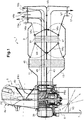
- the figure 1 is a schematic view of a heating, ventilation and / or air conditioning installation 1 intended to equip a motor vehicle to regulate the aerothermal parameters of the air flow distributed in one or more zones of the passenger compartment of the vehicle.
- the housing 3 comprises a first intake mouth 4a for the introduction of an external air flow FE coming from outside the vehicle into the first air intake channel 5 allowing its circulation in the internal volume delimited through the housing 3.
- the box 3 also includes a second inlet mouth 4b for the introduction of a first flow of recycled air FR1 coming from the passenger compartment of the vehicle and circulating again in the internal volume delimited by the box 3.
- the air inlets can be reversed, that is to say that the recycled air FR1 can be applied to the inlet 4a and the outside air FE to the inlet 4b.
- the first air intake channel 5 can be supplied both by the external air flow FE or the first recycled air flow FR1 as well as by a mixture of the two external air flows FE and recycled FR1.
- the outside air flow FE and the first recycling air flow FR1 can be mixed with each other in the first air intake channel 5.
- an air mixing device such as a first mixing flap V1 pivotally mounted allows the outside air flow FE and the first recycled air flow FR1 to be distributed in the desired proportion. first air intake channel 5.
- the mixing flap V1 is movable between two extreme closing positions. In a first closed position called the recycling position, the mixing flap V1 prohibits the passage of the outside air flow FE towards the first air intake channel 5 while allowing a passage of the first recycled air flow FR1 towards the first air intake channel 5. In the second closed position called the external position, the mixing flap V1 prevents the passage of the flow of recycled air FR1 to the first air intake channel 5 while authorizing a passage of the external air flow FE towards the first air intake channel 5.
- the mixing flap V1 is arranged in such a way that it calibrates, in intermediate positions, the proportion of the flow of outside air FE and the first flow of recycled air FR1 entering the first air intake channel 5 .
- the stroke of the first flap V1 is shown diagrammatically by dotted lines starting from the end of the first flap V1 on the figure 1 .
- the second air intake channel 7 is reserved for the introduction of a second flow of recycled air FR2 coming from the passenger compartment and circulating again in the installation 1.
- Different positions of the second flap V2 for managing the flow rate of the second flow of recycled air FR2 are illustrated by way of example on the figure 1 .
- the flow management can be done by way of example depending on the speed of the vehicle.
- the flow rate of this specific recycling can be between 10% and 50% of the flow rate of the aspirated air flow coming from the first air intake channel 5.
- the flow shutter V2 must not be completely closed because a certain amount of air must be allowed to cool the engine.
- the motor-fan unit also called a blower 9 is arranged so as to circulate an air flow from the first air intake channel 5 or from the second air intake channel 7 in the installation 1 and subsequently to the air outlets 15a, 15b and 17, for example a defrosting / defogging outlet 15a, a head ventilation outlet 15b and a foot ventilation mouth 17.
- the air delivered through the defrosting / defogging mouth 15a makes it possible to supply one or more nozzles arranged at the level of the vehicle windshield.
- the head ventilation outlet 15b makes it possible to ventilate an upper zone of the passenger compartment while the foot ventilation outlet 17 makes it possible to ventilate a lower zone of the passenger compartment.
- the blower 9 is arranged downstream of the first intake channel 5 in the direction of flow of the outside air flow FE and the first recycled air flow FR1 so as to circulate an air flow from the first air intake channel 5 in installation 1, more precisely in the first air distribution channel 11, and subsequently towards the outlets 15a and 15b.
- the blower 9 is also arranged downstream of the second intake channel 7 in the direction of flow of the second recycled air flow FR2 so as to circulate an air flow from the second air intake channel 7 in installation 1, more precisely in the second air distribution channel 13, and subsequently towards outlet 17.
- the blower 9 makes it possible to introduce into the first air distribution channel 11 either outside air FE taken from outside the passenger compartment, or re-circulating air taken from inside the passenger compartment says first recirculated air flow FR1, or a mixture of the two, and in the second air distribution channel 13 a permanent recirculated air stream taken from inside the passenger compartment says second air flow recycled FR2.
- the lower part 9b is therefore dedicated to permanent recycling.
- This lower part 9b for permanent recycling can be between 10% and 35% in height of the blower 9.
- the blower 9 comprises a fan and a motor 21 capable of driving the fan in rotation around a drive axis I.
- the fan comprises a wheel 23.
- the electric motor 21 is capable of driving the wheel 23 in rotation so as to set in motion an air flow in the installation 1.
- the wheel 23 is cylindrical.
- the wheel 23 better visible on the figure 3 presents a bowl 25.
- the bowl 25 is made of solid material, so as to form a sealed separation between the upper part 9a of the blower and the lower part 9b of the blower 9. This separation produced by the bowl 25 prevents the flow of air from the first channel air intake 5 to be introduced into the second distribution channel 13 through the lower part 9b of the blower 9, and conversely prevents the air flow from the second air intake channel 7 from being introduced in the first distribution channel 11 through the upper part 9a of the blower 9.
- the bowl 25 comprises substantially in its middle a hub 27 whose function is to mechanically connect the wheel 23 to a drive shaft 29.
- the bowl 25 also has an external peripheral edge 30.
- the wheel 23 also has blades or fins 31, 33 on its periphery.
- first blades 31 extend from the outer peripheral edge 30 of the bowl 25 towards a first outer peripheral edge 35 of the wheel 23 and second blades 33 extend from the outer peripheral edge 30 of the bowl 25 opposite the first blades 31 towards a second external peripheral border 37.
- the blower 9 therefore has a first open end face A delimited by the first external peripheral border 35 and a second open end face B opposite to the first end face A open and delimited by the second external peripheral border 37.
- the blower 9 has a first air suction region and a second air suction region. According to the illustrated embodiment, the first air suction region is located on the side of the first end face A of the cylindrical wheel and the second air suction region is located on the side of the second face end B of the cylindrical wheel.
- the blower wheel 23 draws air through its two opposite open end faces A and B.
- the air coming from the first air intake channel 5 is evacuated by the side of the upper part 9a of the blower in a direction perpendicular to the direction of entry of the air through the first end face A opened.
- the recycled air FR2 coming from the second air intake channel 7 is evacuated through the side of the lower part 9b of the blower 9 according to a direction perpendicular to the direction of entry of the air through the second open end face B.
- the motor 21 comprises a cage 38 which delimits an internal volume of the motor 21.
- the motor 21 includes the motor shaft 29 which passes through the cage 38 on either side along the axis I. According to the example illustrated, the motor shaft 29 opens out on one side of the motor 21 more significantly than on the other side and passes through the hub 27 of the bowl 25 of the wheel 23 to rotate the wheel 23.
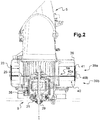
- the housing 3 comprises a volute 39 housing the blower 9.
- the volute 39 is divided into two volumes: a first volume 39a comprising the upper part 9a of the blower 9 and a second volume 39b comprising the lower part 9b of the blower 9.
- the second volume 39b is therefore dedicated to permanent recycling and can be between 10% and 35% in height of the volute 39.
- the volute 39 includes a sealing means 40 arranged between the two volumes 39a and 39b.
- This sealing means 40 comprises a wall 40a separating the two volumes 39a and 39b.
- the wall 40a is permanently arranged in the volute 39 to separate the two air flows from the first intake channel 5 and the second intake channel 7, thereby allowing permanent recycling of the air flow at the level of the second distribution channel 13.
- the wall 40a is arranged in a fixed position in the volute 39 around the blower 9.
- the wall 40a at the blower 9 therefore allows separation into two parts from the origin of the incoming air flows before distribution in the respective channels 11 or 13.
- the sealing means 40 further comprises a means 40b for holding the wall 40a in the volute 39.
- the holding means 40b is made in one piece with the wall 40a.
- the sealing means 40 may comprise a peripheral skirt 40b, of substantially cylindrical shape in the example illustrated.
- the peripheral skirt 40b is connected to the wall 40a by extending substantially vertically with respect to the plane defined by the wall 40a on each side of the wall 40a.
- the peripheral skirt 40b extends more on the side of the wall 40a opposite the first volume 39a of volute communicating with the first air intake channel 5.
- the peripheral skirt 40b can be made in one piece with the wall 40a.
- peripheral skirt 40b is received in a corresponding housing of the volute 39.
- this housing is defined by shoulders 41 on the side walls of the volute 39.
- the cylindrical peripheral skirt 40b thus forms a means holding the wall 40a in the volute 39.
- An installation 1 has been described above with a single wheel 23 driven by a motor 21 for introducing air both into the first air distribution channel 11 and into the second air distribution channel 13. may alternatively provide an installation comprising two wheels respectively associated with an air distribution channel 11 or 13.
- the two air distribution channels 11 and 13 are also separated by a partition 43 arranged between the two air distribution channels 11 and 13.
- the partition 43 is airtight.
- the housing 3 therefore comprises two stages separated by this partition 43; the first stage defining the first air distribution channel 11 and the second stage defining the second air distribution channel 13.
- the air flow sucked by the upper part 9a of the blower 9 coming from the first air intake channel 5 flows in the first distribution channel 11 towards the outlets 15a, 15b without aeraulic communication with the second air distribution channel 13.
- the flow of recycled air FR2 sucked in by the second part 9b of the blower 9 coming from the second air intake channel 7 s flows in the second air distribution channel 13 to the outlet 17 without air communication with the first air distribution channel 11.
- the partition 43 may not extend over the entire length of the housing 3 and provision may be made for a switching flap V3 .
- the flap V3 is pivotally mounted between a closed position as illustrated on the figure 1 and an open position allowing communication between the two air distribution channels 11 and 13.
- the housing 3 also houses heat treatment means 45, 47 of the air prior to its evacuation from the housing 3 to the passenger compartment.
- the heat treatment means 45, 47 are arranged in the first air distribution duct 11 and in the second distribution duct 13. More specifically, the heat treatment means 45, 47 are common to the two air distribution channels 11 and 13.
- the heat treatment means 45, 47 can respectively comprise an internal partition 49, 51 making it possible to separate the air flows coming from the first 5 or from the second 7 air intake channel and passing through the treatment means thermal 45 and 47.
- the heat treatment means 45, 47 are in particular an evaporator 45 provided for cooling the air passing through it and a heating device such as a radiator 47 able to heat this air.
- the radiator 47 is possibly associated with electrical resistors of the resistance type with a positive temperature coefficient, commonly known as “PTC”.
- the heating device can be an air-water exchanger, or air oil, that is to say in which there is a heat exchange between air and water or oil.
- distribution flaps V4 1 , V4 2 ; V5 1 , V5 2 can be arranged upstream and downstream of the radiator 47.
- the flap V4 1 arranged upstream of the radiator 47 and the flap V5 1 arranged downstream of the radiator 47 according to the direction of flow of the air flow from the first channel air intake 5 are suitable for authorizing or preventing the passage of the air flow leaving the evaporator 45 through the radiator 47.
- the air flow leaving the evaporator 45 can bypass the radiator 47.
- the shutters V4 1 and V5 1 are pivotally mounted between two extreme positions allowing or preventing the passage of all the air flow leaving the evaporator through the radiator 47.
- the shutters V4 1 and V5 1 can be controlled in intermediate positions so as to distribute a flow of air to be heated in the radiator 47 and a flow of air not to be heated which does not pass through the radiator 47.
- the flap V4 2 arranged upstream of the radiator 47 and the flap V5 2 arranged downstream of the radiator 47 in the direction of flow of the recycled air flow FR2 in coming from the second air intake channel 7 are capable of authorizing or preventing the passage of the air flow leaving the evaporator 45 through the radiator 47.
- the air flow leaving the evaporator 45 can bypass the radiator 47.
- the shutters V4 2 and V5 2 are pivotally mounted between two extreme positions allowing or preventing the passage of all the air flow leaving the evaporator through the radiator 47.
- the shutters V4 2 and V5 2 can be controlled in intermediate positions so as to distribute a flow of air to be heated in the radiator 47 and a flow of air not to be heated which does not pass through the radiator 47.
- each air outlet 15a, 15b, 17 can be provided with a respective air distribution flap V6a, V6b, and V7 which is operable between an open position in which the air distribution flap V6a, V6b, and V7 allows an air passage through the air outlet 15a, 15b, 17 that the air distribution flap V6a, V6b, and V7 equips and a position closure in which the air distribution flap V6a, V6b, and V7 prohibits such passage.
- such an installation 1 comprising a two-stage housing 3 makes it possible to manage the air by using the first air intake channel 5 only for the first stage by taking outside, recycled air or a mixture of the two , and always taking air directly from the passenger compartment for the second floor.
- the first stage feeds in particular the high ventilation outlets and the defrosting / demisting outlets, while the second stage feeds the low ventilation outlets arriving at the users' feet.
- the air flow for the first stage can be distributed according to the needs for defrosting and / or thermal comfort in the passenger compartment, in particular one can send more air flow outside, consequently drier than a flow of recirculating air, to avoid fogging of the windshield for example.
- the two air flows are separated from the start by dividing the blower 9 so that it is not necessary to provide a complicated air management system with shutters to allow recycling of the air flow for the second stage of the housing 3.
- the separation between the two stages of the housing 3 can be done in a simple manner using a partition 43 between the two air distribution channels 11, 13.
Description
La présente invention concerne une installation de chauffage, ventilation et/ou climatisation pour un habitacle de véhicule automobile permettant le contrôle de la température de flux d'air dans une ou plusieurs zones de l'habitacle d'un véhicule automobile. Le document
Un véhicule automobile est couramment équipé d'une installation de chauffage, de ventilation et/ou de climatisation qui est destinée à réguler les paramètres aérothermiques de l'air distribué dans l'habitacle, en particulier la température d'un flux d'air délivré par l'installation à l'intérieur de l'habitacle.A motor vehicle is commonly equipped with a heating, ventilation and / or air conditioning installation which is intended to regulate the aerothermal parameters of the air distributed in the passenger compartment, in particular the temperature of a flow of air delivered. by installation inside the passenger compartment.
Dans sa généralité, l'installation comprend un boîtier délimité par des cloisons à travers lesquelles sont ménagées des ouvertures, dont au moins une entrée d'air et au moins une bouche de distribution d'air.In general, the installation comprises a housing delimited by partitions through which are formed openings, including at least one air inlet and at least one air distribution mouth.
De façon connue, le boîtier loge généralement un groupe moto-ventilateur également appelé pulseur pour faire circuler le flux d'air depuis l'entrée d'air vers la bouche de distribution d'air. Le boîtier loge aussi des moyens de traitement thermique pour réchauffer et/ou refroidir le flux d'air préalablement à sa distribution à l'intérieur de l'habitacle à travers la bouche de distribution d'air. À titre d'exemple, les moyens de traitement thermique peuvent comprendre un évaporateur qui est destiné à refroidir l'air le traversant, et un radiateur, éventuellement associé à un radiateur additionnel, qui est destiné à réchauffer l'air qui le traverse.In a known manner, the box generally houses a motor-fan group also called a blower to circulate the air flow from the air inlet to the air distribution mouth. The housing also houses heat treatment means for heating and / or cooling the air flow prior to its distribution inside the passenger compartment through the air distribution mouth. By way of example, the heat treatment means may include an evaporator which is intended to cool the air passing through it, and a radiator, possibly associated with an additional radiator, which is intended to heat the air passing through it.
L'installation peut de plus comprendre plusieurs volets pour contrôler le passage d'air à travers des bouches de distribution correspondant à des sorties d'aération ou de ventilation s'ouvrant dans l'habitacle du véhicule, ou encore à une sortie de dégivrage/désembuage notamment du pare-brise du véhicule.The installation may also include several flaps to control the passage of air through distribution outlets corresponding to ventilation or ventilation outlets opening in the passenger compartment of the vehicle, or even to a defrost outlet / demisting in particular of the vehicle windshield.
Par ailleurs, l'air circulant dans une telle installation peut être un flux d'air extérieur, ou le flux d'air provenant de l'habitacle circulant de nouveau dans l'installation, on parle alors de flux d'air recyclé ou recirculant, ou encore un mélange des deux. Un volet de mixage peut répartir la proportion d'air extérieur et la proportion d'air recyclé.Furthermore, the air circulating in such an installation can be a flow of outside air, or the air flow coming from the passenger compartment circulating again in the installation, this is called a recirculated or recirculating air flow. , or a mixture both. A mixing flap can distribute the proportion of outside air and the proportion of recycled air.
Lorsque la température extérieure est basse et si le flux d'air provenant de l'habitacle est recyclé pour le chauffage de l'habitacle, il existe un risque d'apparition de buée sur les vitres du véhicule, notamment sur le pare-brise. En effet, la présence des passagers dans l'habitacle contribue à charger le flux d'air recyclé en humidité qui, après un certain temps d'utilisation, se condense sur les vitres dès lors que la température extérieure permet d'atteindre le point de rosée.When the outside temperature is low and if the air flow from the passenger compartment is recycled for heating the passenger compartment, there is a risk of the appearance of fogging on the vehicle windows, in particular on the windshield. Indeed, the presence of passengers in the passenger compartment contributes to charging the flow of recycled air with moisture which, after a certain period of use, condenses on the windows as soon as the outside temperature makes it possible to reach the point of dew.
Afin d'éviter ce problème, de l'air extérieur plus sec que de l'air recyclé doit de préférence être soufflé dans l'habitacle.To avoid this problem, drier outside air than recirculated air should preferably be blown into the passenger compartment.
Cependant, cette solution n'est pas adaptée pour un véhicule électrique, car la température de l'air extérieur étant basse, une grande puissance électrique est nécessaire pour réaliser le chauffage, et le temps d'autonomie électrique du véhicule peut être réduit.However, this solution is not suitable for an electric vehicle, since the temperature of the outside air being low, a large electric power is necessary to carry out the heating, and the electric autonomy time of the vehicle can be reduced.
Au contraire, afin de réduire la consommation électrique le recyclage de l'air de l'habitacle pour réaliser le chauffage est préférable.On the contrary, in order to reduce electrical consumption recycling the air in the passenger compartment for heating is preferable.
Pour remédier à ces problèmes, on connaît des installations à deux niveaux, c'est-à-dire comprenant deux canaux de distribution d'air logeant les moyens de traitement thermique d'une installation classique pour assurer le confort thermique dans l'habitacle, et chaque niveau peut être alimenté par un flux d'air de même origine ou d'origine distincte.To remedy these problems, two-level installations are known, that is to say comprising two air distribution channels housing the heat treatment means of a conventional installation to ensure thermal comfort in the passenger compartment, and each level can be supplied by an air flow of the same origin or of separate origin.
Ainsi, l'alimentation en flux d'air extérieur et/ou en flux d'air recyclé peut être sélectionnée en fonction des besoins, par exemple en envoyant un flux d'air extérieur vers le pare-brise pour répondre au problème d'embuage des vitres du véhicule, notamment du pare-brise, et en envoyant un flux d'air recyclé vers des sorties d'aération des pieds dans l'habitacle pour un chauffage plus rapide.Thus, the supply of external air flow and / or of recycled air flow can be selected as required, for example by sending a flow of external air to the windshield to respond to the problem of fogging. vehicle windows, in particular the windshield, and by sending a flow of recycled air to the foot ventilation outlets in the passenger compartment for faster heating.
Cependant, cette solution nécessite un système de gestion des flux d'air pour répartir les flux d'air extérieur et recyclé selon les besoins.However, this solution requires an air flow management system to distribute the flow of outside and recycled air as needed.
Un tel système est contraignant car requiert des conduits de contournement pour séparer les flux d'air et distribuer par exemple un flux d'air recyclé dans le deuxième niveau formant par exemple une partie inférieure de l'installation tandis qu'un flux d'air extérieur neuf doit être distribué dans le premier niveau formant dans ce cas la partie supérieure de l'installation. La présence des conduits de contournement implique un encombrement plus important de l'installation dans le véhicule.Such a system is restrictive because it requires bypass ducts to separate the air flows and distribute, for example, a recirculated air flow in the second level forming for example a lower part of the installation while a flow of fresh outside air must be distributed in the first level in this case forming the upper part of the installation. The presence of the bypass conduits implies a larger bulk of the installation in the vehicle.
De plus, un tel système comporte un ou plusieurs volets pour répartir les flux d'air et est donc plus complexe.In addition, such a system has one or more flaps to distribute the air flows and is therefore more complex.
L'invention a donc pour objectif de proposer une installation améliorée permettant de résoudre au moins partiellement les inconvénients de l'art antérieur.The invention therefore aims to provide an improved installation to at least partially resolve the drawbacks of the prior art.
À cet effet, l'invention a pour objet une installation de chauffage, ventilation et/ou climatisation pour un habitacle de véhicule automobile comprenant :
- un premier canal d'admission d'air,
- un premier canal de distribution d'air comprenant au moins une première sortie d'air dans l'habitacle et communiquant avec le premier canal d'admission d'air, et
- un deuxième canal de distribution d'air comprenant une deuxième sortie d'air, ladite installation comprenant en outre un deuxième canal d'admission réservé à un flux d'air recyclé provenant de l'habitacle et en communication aéraulique avec le deuxième canal de distribution d'air, de façon à alimenter le deuxième canal de distribution d'air uniquement par le flux d'air recyclé provenant du deuxième canal d'admission d'air.
caractérisée en ce que le boîtier comprend une première bouche d'admission pour l'introduction d'un flux d'air extérieur et une deuxième bouche d'admission pour l'introduction d'un premier flux d'air recyclé dans le premier canal d'admission d'air.
- a first air intake channel,
- a first air distribution channel comprising at least a first air outlet in the passenger compartment and communicating with the first air intake channel, and
- a second air distribution channel comprising a second air outlet, said installation further comprising a second intake channel reserved for a flow of recycled air coming from the passenger compartment and in aeraulic communication with the second distribution channel air, so as to supply the second air distribution channel only with the recirculated air flow coming from the second air intake channel.
characterized in that the housing comprises a first intake opening for the introduction of an outside air flow and a second intake opening for the introduction of a first recirculated air flow into the first air channel 'air intake.
Cette solution permet d'implanter une aspiration dédiée au recyclage au niveau du deuxième canal d'admission d'air.This solution makes it possible to set up a suction dedicated to recycling at the level of the second air intake channel.
L'invention propose ainsi de distribuer vers les sorties d'air, des flux d'air qui peuvent présenter selon le cas une origine distincte ou une origine commune. Plus précisément, un flux d'air provenant du premier canal d'admission d'air pouvant être alimenté soit par un flux d'air extérieur, soit par un flux d'air recyclé, soit encore un mélange des deux, peut être distribué vers une ou plusieurs premières sorties d'air au niveau du premier canal de distribution d'air.The invention thus proposes to distribute to the air outlets, air flows which may, depending on the case, have a distinct origin or a common origin. More specifically, an air flow coming from the first air intake channel which can be supplied either by an external air flow or by a recycled air flow, or even a mixture of the two, can be distributed to one or more first air outlets at the first air distribution channel.
Au contraire, un flux d'air d'origine distincte du premier flux d'air et totalement recyclé peut être dirigé vers une deuxième sortie d'air séparée des premières sorties d'air, au niveau du deuxième canal de distribution d'air.On the contrary, an air flow of origin separate from the first air flow and totally recycled can be directed to a second air outlet separated from the first outlets air, at the second air distribution channel.
Le recyclage permanent d'une partie du flux d'air distribué dans l'habitacle permet de répondre à un besoin de chauffage rapide de l'air tandis que pour des raisons de désembuage par exemple un flux d'air extérieur neuf ou mélangé avec de l'air recyclé peut être envoyé vers le pare-brise.The permanent recycling of part of the air flow distributed in the passenger compartment makes it possible to meet a need for rapid heating of the air while, for reasons of demisting, for example a flow of fresh outside air or mixed with recycled air can be sent to the windshield.
Avec cette solution, il n'est pas nécessaire de prévoir de conduits de contournement d'un flux d'air pour être distribué de façon sélective dans un canal de distribution d'air.With this solution, it is not necessary to provide conduits for bypassing an air flow in order to be distributed selectively in an air distribution channel.
De plus, l'origine des flux d'air distribués dans chaque canal étant distincte, il n'est pas non plus nécessaire de prévoir de volets pour la répartition de ces deux flux d'air devant alimenter d'une part le premier canal de distribution d'air et d'autre part le deuxième canal de distribution d'air.In addition, the origin of the air flows distributed in each channel being distinct, it is also not necessary to provide flaps for the distribution of these two air flows which must supply the first channel of air distribution and on the other hand the second air distribution channel.
Selon un aspect de l'invention, l'installation comprend un groupe moto-ventilateur apte à introduire de l'air dans le premier canal de distribution d'air et dans le deuxième canal de distribution d'air, et comprenant :
- une première partie communiquant d'une part avec le premier canal d'admission d'air et d'autre part avec le premier canal de distribution d'air, et
- une deuxième partie communiquant d'une part avec le deuxième canal d'admission d'un flux d'air recyclé et d'autre part avec le deuxième canal de distribution d'air.
- a first part communicating on the one hand with the first air intake channel and on the other hand with the first air distribution channel, and
- a second part communicating on the one hand with the second intake channel of a recycled air flow and on the other hand with the second air distribution channel.
Le recyclage spécifique est implanté du côté du groupe moto-ventilateur. Ce recyclage spécifique fonctionne toujours dès que le groupe moto-ventilateur est actionné.Specific recycling is implemented on the motor-fan unit side. This specific recycling always works as soon as the motor-fan unit is activated.
Selon un mode de réalisation, le groupe moto-ventilateur comprend une roue présentant un bol réalisé en matériau plein et s'étendant entre la première partie et la deuxième partie du groupe moto-ventilateur. Le bol permet de diviser en deux le groupe moto-ventilateur et assure ainsi une séparation des flux d'air provenant du premier canal d'admission d'air et du deuxième canal d'admission d'air dès l'origine des flux d'air.According to one embodiment, the motor-fan unit comprises a wheel having a bowl made of solid material and extending between the first part and the second part of the motor-fan group. The bowl makes it possible to divide the motor-fan group in two and thus ensures separation of the air flows from the first air intake channel and the second air intake channel from the origin of the air flows. air.
Selon un aspect de l'invention, le groupe moto-ventilateur comprend des premières pales s'étendant depuis un bord périphérique externe du bol vers une première bordure périphérique externe de la roue et des secondes pales s'étendant à l'opposé des premières pales depuis le bord périphérique externe du bol vers une deuxième bordure périphérique externe de la roue.According to one aspect of the invention, the motor-fan unit comprises first blades extending from an external peripheral edge of the bowl towards a first external peripheral edge of the wheel and second blades extending opposite to the first blades from the outer peripheral edge of the bowl to a second outer peripheral edge of the wheel.
Le groupe moto-ventilateur présente deux régions d'aspiration opposées distinctes. La deuxième région d'aspiration est dédiée au recyclage spécifique.The motor-fan unit has two separate opposite suction regions. The second suction region is dedicated to specific recycling.
Selon un autre aspect de l'invention, l'installation comprend :
- une volute logeant le groupe moto-ventilateur et
- un moyen d'étanchéité séparant la volute en deux volumes, le premier volume de volute comprenant la première partie du groupe moto-ventilateur, et le deuxième volume de volute comprenant la deuxième partie du groupe moto-ventilateur.
- a volute housing the motor-fan unit and
- a sealing means separating the volute into two volumes, the first volume of volute comprising the first part of the motor-fan unit, and the second volume of volute comprising the second part of the motor-fan group.
Cette volute est séparée en deux volumes définissant ainsi une partie supérieure et une partie inférieure.This volute is separated into two volumes thus defining an upper part and a lower part.
La partie supérieure communique avec le premier canal d'admission d'air correspondant à une entrée d'air classique pouvant être alimenté par de l'air extérieur et/ou de l'air recyclé, qui passe par la volute puis est introduit dans le premier canal de distribution d'air jusqu'aux sorties par exemple de dégivrage et d'aération de tête dans l'habitacle.The upper part communicates with the first air intake channel corresponding to a conventional air inlet which can be supplied by outside air and / or recycled air, which passes through the volute then is introduced into the first air distribution channel to the outlets, for example defrost and head ventilation in the passenger compartment.
La partie inférieure communique avec le deuxième canal d'admission d'air correspondant au recyclage spécifique pour introduire un flux d'air toujours recyclé dans le deuxième canal de distribution d'air jusqu'à une sortie par exemple d'aération des pieds dans l'habitacle.The lower part communicates with the second air intake channel corresponding to the specific recycling in order to introduce a flow of air which is always recycled into the second air distribution channel up to an outlet, for example for aerating the feet in the cabin.
Le moyen d'étanchéité peut comprendre une paroi agencée entre les deux volumes de la volute et un moyen de maintien de la paroi dans la volute. La paroi permet de partitionner de façon simple la volute.The sealing means may comprise a wall arranged between the two volumes of the volute and a means for holding the wall in the volute. The wall allows you to easily partition the scroll.
Selon un mode de réalisation, le moyen de maintien est réalisé d'une seule pièce avec la paroi.According to one embodiment, the holding means is made in one piece with the wall.
Le moyen d'étanchéité peut comprendre une jupe périphérique sensiblement cylindrique formant maintien de la paroi et reçu dans un logement complémentaire de la volute.The sealing means may comprise a substantially cylindrical peripheral skirt forming a support for the wall and received in a housing complementary to the volute.
Selon un mode de réalisation, ladite installation comprend au moins un volet de débit agencé dans le deuxième canal d'admission d'air de façon à régler le débit d'air du flux d'air recyclé. Le volet de débit dédié au recyclage permanent permet de gérer le débit du flux d'air recyclé, par exemple en fonction de paramètres du véhicule tel que la vitesse du véhicule.According to one embodiment, said installation comprises at least one flow shutter arranged in the second air intake channel so as to adjust the air flow of the recirculated air flow. The flow shutter dedicated to permanent recycling makes it possible to manage the flow of the recirculated air flow, for example as a function of vehicle parameters such as the speed of the vehicle.
Selon un aspect de l'invention, l'installation comprend une cloison de séparation agencée entre le premier canal de distribution d'air et le deuxième canal de distribution d'air.According to one aspect of the invention, the installation comprises a partition wall arranged between the first air distribution channel and the second air distribution channel.
Selon un autre aspect de l'invention, l'installation comprend des moyens de traitement thermique de flux d'air agencés dans le premier canal de distribution d'air et dans le deuxième canal de distribution d'air. Lesdits moyens de traitement thermique sont communs aux deux canaux de distribution d'air.According to another aspect of the invention, the installation comprises means for heat treatment of air flows arranged in the first air distribution channel and in the second air distribution channel. Said heat treatment means are common to the two air distribution channels.
Lesdits moyens de traitement thermique peuvent comporter respectivement une cloison interne de séparation des flux d'air traversant le premier canal de distribution d'air et le deuxième canal de distribution d'air.Said heat treatment means may respectively comprise an internal partition for separating the air flows passing through the first air distribution channel and the second air distribution channel.
La cloison entre les deux canaux de distribution et les cloisons internes au niveau des moyens de traitement thermique permettant la séparation entre les deux flux d'air jusqu'à la délivrance dans les sorties d'air respectives.The partition between the two distribution channels and the internal partitions at the level of the heat treatment means allowing the separation between the two air flows until delivery into the respective air outlets.
Selon un mode de réalisation de l'invention, un volet de commutation peut être agencé pour mettre en communication les deux canaux de distribution d'air, par exemple pour envoyer une quantité d'air plus importante vers une des sorties d'air.According to one embodiment of the invention, a switching flap can be arranged to put the two air distribution channels in communication, for example to send a larger quantity of air to one of the air outlets.
Selon un mode de réalisation particulier, ladite au moins une première sortie est une sortie de dégivrage orientée vers le pare-brise dudit véhicule ou une sortie d'aération de tête des passagers dans l'habitacle dudit véhicule, et la deuxième sortie est une sortie d'aération orientée vers les pieds des passagers dans l'habitacle.According to a particular embodiment, said at least one first outlet is a defrost outlet oriented towards the windshield of said vehicle or a passenger head ventilation outlet in the passenger compartment of said vehicle, and the second outlet is an outlet ventilation oriented towards the feet of passengers in the passenger compartment.
En envoyant uniquement un flux d'air recyclé vers les pieds, le chauffage peut être réalisé plus rapidement. La proportion d'air extérieur neuf et d'air recyclé à diriger vers les sorties de dégivrage/désembuage et d'aération de tête peut être répartie selon les besoins de dégivrage.By sending only a stream of recycled air to the feet, heating can be achieved more quickly. The proportion of fresh outside air and recycled air to be directed to the defrost / defog and head ventilation outlets can be distributed according to the defrost requirements.
D'autres caractéristiques et avantages de l'invention apparaîtront plus clairement à la lecture de la description suivante, donnée à titre d'exemple illustratif et non limitatif, et des dessins annexés parmi lesquels :
- la
figure 1 est une vue en coupe d'une installation de chauffage, ventilation et/ou climatisation à deux étages selon l'invention, - la
figure 2 est une vue schématique d'une volute de l'installation de lafigure 1 comprenant un groupe moto-ventilateur, - la
figure 3 est une vue de la roue du groupe moto-ventilateur de lafigure 2 , - la
figure 4a est une première vue en perspective de la roue de lafigure 3 , et - la
figure 4b est une deuxième vue en perspective de la roue de lafigure 3 .
- the
figure 1 is a sectional view of a two-stage heating, ventilation and / or air conditioning installation according to the invention, - the
figure 2 is a schematic view of a volute of the installation of thefigure 1 including a motor-fan unit, - the
figure 3 is a view of the impeller of the motor-fan unit of thefigure 2 , - the
figure 4a is a first perspective view of the wheel of thefigure 3 , and - the
figure 4b is a second perspective view of the wheel of thefigure 3 .
Dans ces figures, les éléments sensiblement identiques portent les mêmes références.In these figures, the substantially identical elements have the same references.
La
L'installation 1 comporte un boîtier 3 comprenant :
- un premier
canal d'admission d'air 5, - un deuxième
canal d'admission d'air 7, - une groupe moto-
ventilateur 9 également appelé pulseur pour introduire de l'air dans l'installation 1, - un premier canal
de distribution d'air 11, - un second canal
de distribution d'air 13, et - plusieurs sorties d'air 15a,
15b et 17.
- a first
air intake channel 5, - a second
air intake channel 7, - a motor-
fan unit 9 also called a blower to introduce air into the installation 1, - a first
air distribution channel 11, - a second
air distribution channel 13, and -
several air outlets
Le boîtier 3 comprend une première bouche d'admission 4a pour l'introduction d'un flux d'air extérieur FE provenant de l'extérieur du véhicule dans le premier canal d'admission d'air 5 permettant sa circulation dans le volume interne délimité par le boîtier 3.The
Le boîtier 3 comprend aussi une deuxième bouche d'admission 4b pour l'introduction d'un premier flux d'air recyclé FR1 provenant de l'habitacle du véhicule et circulant de nouveau dans le volume interne délimité par le boîtier 3.The
Bien entendu, les entrées d'air peuvent être inversées, c'est-à-dire que l'air recyclé FR1 peut être appliqué à l'entrée 4a et l'air extérieur FE à l'entrée 4b.Of course, the air inlets can be reversed, that is to say that the recycled air FR1 can be applied to the
Le premier canal d'admission d'air 5 peut être alimenté aussi bien par le flux d'air extérieur FE ou le premier flux d'air recyclé FR1 que par un mélange des deux flux d'air extérieur FE et recyclé FR1. Le flux d'air extérieur FE et le premier flux d'air de recyclage FR1 sont susceptibles d'être mélangés l'un avec l'autre dans le premier canal d'admission d'air 5.The first
À cet effet, un organe de mixage d'air, tel qu'un premier volet de mixage V1, monté pivotant permet de répartir en proportion voulue le flux d'air extérieur FE et le premier flux d'air recyclé FR1 à introduire dans le premier canal d'admission d'air 5.To this end, an air mixing device, such as a first mixing flap V1, pivotally mounted allows the outside air flow FE and the first recycled air flow FR1 to be distributed in the desired proportion. first
Le volet de mixage V1 est mobile entre deux positions extrêmes de fermeture. Dans une première position de fermeture dite position de recyclage, le volet de mixage V1 interdit le passage du flux d'air extérieur FE vers le premier canal d'admission d'air 5 tout en autorisant un passage du premier flux d'air recyclé FR1 vers le premier canal d'admission d'air 5. Dans la deuxième position de fermeture dite position extérieure, le volet de mixage V1 interdit le passage du flux d'air recyclé FR1 vers le premier canal d'admission d'air 5 tout en autorisant un passage du flux d'air extérieur FE vers le premier canal d'admission d'air 5.The mixing flap V1 is movable between two extreme closing positions. In a first closed position called the recycling position, the mixing flap V1 prohibits the passage of the outside air flow FE towards the first
Le volet de mixage V1 est agencé de telle façon qu'il calibre, dans des positions intermédiaires, la proportion du flux d'air extérieur FE et du premier flux d'air recyclé FR1 entrant dans le premier canal d'admission d'air 5.The mixing flap V1 is arranged in such a way that it calibrates, in intermediate positions, the proportion of the flow of outside air FE and the first flow of recycled air FR1 entering the first
La course du premier volet V1 est schématisée par des pointillés partant de l'extrémité du premier volet V1 sur la
Le deuxième canal d'admission d'air 7 est quant à lui réservé à l'introduction d'un deuxième flux d'air recyclé FR2 provenant de l'habitacle et circulant de nouveau dans l'installation 1.The second
On peut prévoir un deuxième volet V2 agencé dans le deuxième canal d'admission d'air 7. Il s'agit d'un volet de débit monté pivotant de façon à contrôler le débit du deuxième flux d'air recyclé FR2.One can provide a second flap V2 arranged in the second
Différentes positions du deuxième volet V2 pour gérer le débit du deuxième flux d'air recyclé FR2 sont illustrées à titre d'exemple sur la
Le débit de ce recyclage spécifique peut être compris entre 10 % et 50 % du débit du flux d'air aspiré provenant du premier canal d'admission d'air 5.The flow rate of this specific recycling can be between 10% and 50% of the flow rate of the aspirated air flow coming from the first
Cependant, le volet de débit V2 ne doit pas être entièrement fermé car il faut laisser passer une certaine quantité d'air pour le refroidissement du moteur.However, the flow shutter V2 must not be completely closed because a certain amount of air must be allowed to cool the engine.
Le groupe moto-ventilateur également appelé pulseur 9 est agencé de manière à faire circuler un flux d'air depuis le premier canal d'admission d'air 5 ou depuis le deuxième canal d'admission d'air 7 dans l'installation 1 et par la suite vers les sorties d'air 15a, 15b et 17, par exemple une sortie de dégivrage/désembuage 15a, une sortie d'aération de tête 15b et une bouche d'aération de pieds 17.The motor-fan unit also called a
L'air délivré à travers la bouche de dégivrage/désembuage 15a permet d'alimenter une ou plusieurs buses agencées au niveau du pare-brise du véhicule. La sortie d'aération de tête 15b permet de ventiler une zone supérieure de l'habitacle tandis que la sortie d'aération de pieds 17 permet de ventiler une zone inférieure de l'habitacle.The air delivered through the defrosting /
Plus précisément, le pulseur 9 est agencé en aval du premier canal d'admission 5 selon le sens d'écoulement du flux d'air extérieur FE et du premier flux d'air recyclé FR1 de manière à faire circuler un flux d'air depuis le premier canal d'admission d'air 5 dans l'installation 1, plus précisément dans le premier canal de distribution d'air 11, et par la suite vers les sorties 15a et 15b.More specifically, the
Le pulseur 9 est également agencé en aval du deuxième canal d'admission 7 selon le sens d'écoulement du deuxième flux d'air recyclé FR2 de manière à faire circuler un flux d'air depuis le deuxième canal d'admission d'air 7 dans l'installation 1, plus précisément dans le deuxième canal de distribution d'air 13, et par la suite vers la sortie 17.The
Le pulseur 9 permet d'introduire dans le premier canal de distribution d'air 11 soit de l'air extérieur FE prélevé à l'extérieur de l'habitacle, soit de l'air re-circulant prélevé à l'intérieur de l'habitacle dit premier flux d'air recyclé FR1, soit encore un mélange des deux, et dans le deuxième canal de distribution d'air 13 un flux d'air recyclé permanent prélevé à l'intérieur de l'habitacle dit deuxième flux d'air recyclé FR2.The
À cet effet, comme cela est mieux visible sur la
- une première partie 9a dite partie supérieure communiquant avec le premier
canal d'admission d'air 5 et avec le premier canal dedistribution d'air 11 et - une deuxième partie 9b dite partie inférieure communiquant avec le deuxième
canal d'admission d'air 7 et avec le deuxième canalde distribution d'air 13.
- a
first part 9a called the upper part communicating with the firstair intake channel 5 and with the firstair distribution channel 11 and - a second part 9b, called the lower part, communicating with the second
air intake channel 7 and with the secondair distribution channel 13.
La partie inférieure 9b est donc dédiée au recyclage permanent. Cette partie inférieure 9b pour le recyclage permanent peut être comprise entre 10 % et 35 % en hauteur du pulseur 9.The lower part 9b is therefore dedicated to permanent recycling. This lower part 9b for permanent recycling can be between 10% and 35% in height of the
Plus précisément, le pulseur 9 comprend un ventilateur et un moteur 21 apte à entraîner en rotation le ventilateur autour d'un axe d'entraînement I.More specifically, the
Le ventilateur comprend une roue 23. Le moteur électrique 21 est apte à entraîner en rotation la roue 23 de façon à mettre en mouvement un flux d'air dans l'installation 1.The fan comprises a
Selon le mode de réalisation illustré la roue 23 est cylindrique.According to the illustrated embodiment the
La roue 23 mieux visible sur la
Le bol 25 est réalisé en matériau plein, de manière à former une séparation étanche entre la partie supérieure 9a du pulseur et la partie inférieure 9b du pulseur 9. Cette séparation réalisée par le bol 25 empêche au flux d'air provenant du premier canal d'admission d'air 5 d'être introduit dans le deuxième canal de distribution 13 par la partie inférieure 9b du pulseur 9, et inversement empêche au flux d'air provenant du deuxième canal d'admission d'air 7 d'être introduit dans le premier canal de distribution 11 par la partie supérieure 9a du pulseur 9.The
Le bol 25 comporte sensiblement en son milieu un moyeu 27 dont la fonction est de relier mécaniquement la roue 23 à un arbre moteur 29. Le bol 25 présente de plus un bord périphérique externe 30.The
Par ailleurs, la roue 23 présente en outre sur son pourtour des pales ou ailettes 31, 33.Furthermore, the
En référence aux
Le pulseur 9 présente donc une première face d'extrémité A ouverte délimitée par la première bordure périphérique externe 35 et une deuxième face d'extrémité B ouverte opposée à la première face d'extrémité A ouverte et délimitée par la deuxième bordure périphérique externe 37.The
Le pulseur 9 présente une première région d'aspiration d'air et une deuxième région d'aspiration d'air. Selon le mode de réalisation illustré, la première région d'aspiration d'air est située du côté de la première face d'extrémité A de la roue cylindrique et la deuxième région d'aspiration d'air est située du côté de la deuxième face d'extrémité B de la roue cylindrique. La roue 23 de pulseur aspire l'air par ses deux faces d'extrémité A et B ouvertes opposées.The
Dans l'exemple illustré sur la
Concernant le moteur 21, en se référant de nouveau à la
Le moteur 21 comprend l'arbre moteur 29 qui traverse la cage 38 de part et d'autre selon l'axe I. Selon l'exemple illustré, l'arbre moteur 29 débouche d'un côté du moteur 21 de manière plus importante que de l'autre côté et passe à travers le moyeu 27 du bol 25 de la roue 23 pour entraîner en rotation la roue 23.The
Par ailleurs, le boîtier 3 comprend une volute 39 logeant le pulseur 9.Furthermore, the
La volute 39 est divisée en deux volumes : un premier volume 39a comprenant la partie supérieure 9a du pulseur 9 et un deuxième volume 39b comprenant la partie inférieure 9b du pulseur 9.The
Le deuxième volume 39b est donc dédié au recyclage permanent et peut être compris entre 10 % et 35 % en hauteur de la volute 39.The
Afin d'empêcher toute communication aéraulique entre la partie supérieure 9a et la partie inférieure 9b, la volute 39 comporte un moyen d'étanchéité 40 agencé entre les deux volumes 39a et 39b.In order to prevent any air communication between the
Ce moyen d'étanchéité 40 comprend une paroi 40a séparant les deux volumes 39a et 39b.This sealing means 40 comprises a
La paroi 40a est agencée de façon permanente dans la volute 39 pour séparer les deux flux d'air provenant du premier canal d'admission 5 et du deuxième canal d'admission 7, en permettant ainsi un recyclage permanent du flux d'air au niveau du deuxième canal de distribution 13. La paroi 40a est agencée en position fixe dans la volute 39 autour du pulseur 9.The
La paroi 40a au niveau du pulseur 9 permet donc une séparation en deux parties dès l'origine des flux d'air entrants avant distribution dans les canaux respectifs 11 ou 13.The
Le moyen d'étanchéité 40 comprend en outre un moyen de maintien 40b de la paroi 40a dans la volute 39.The sealing means 40 further comprises a
Selon le mode de réalisation illustré le moyen de maintien 40b est réalisé d'une seule pièce avec la paroi 40a.According to the illustrated embodiment, the holding means 40b is made in one piece with the
À titre d'exemple, le moyen d'étanchéité 40 peut comprendre une jupe périphérique 40b, de forme sensiblement cylindrique dans l'exemple illustré. La jupe périphérique 40b est raccordée à la paroi 40a en s'étendant sensiblement verticalement par rapport au plan défini par la paroi 40a de chaque côté de la paroi 40a. Dans l'exemple illustré sur la
La jupe périphérique 40b peut être réalisée d'une seule pièce avec la paroi 40a.The
De plus, la jupe périphérique 40b est reçue dans un logement correspondant de la volute 39. Selon l'exemple illustré, ce logement est défini par des épaulements 41 sur les parois latérales de la volute 39. La jupe périphérique cylindrique 40b forme ainsi un moyen de maintien de la paroi 40a dans la volute 39.In addition, the
On a décrit ci-dessus une installation 1 avec une seule roue 23 entraînée par un moteur 21 pour introduire de l'air aussi bien dans le premier canal de distribution d'air 11 que dans le deuxième canal de distribution d'air 13. On peut prévoir en variante une installation comprenant deux roues respectivement associées à un canal de distribution d'air 11 ou 13.An installation 1 has been described above with a
En ce qui concerne les deux canaux de distribution d'air 11 et 13, en se référant de nouveau à la
Le boîtier 3 comprend donc deux étages séparés par cette cloison 43 ; le premier étage définissant le premier canal de distribution d'air 11 et le deuxième étage définissant le deuxième canal de distribution d'air 13.The
Ainsi, le flux d'air aspiré par la partie supérieure 9a du pulseur 9 provenant du premier canal d'admission d'air 5 s'écoule dans le premier canal de distribution 11 vers les sorties 15a, 15b sans communication aéraulique avec le deuxième canal de distribution d'air 13. De même, le flux d'air recyclé FR2 aspiré par la deuxième partie 9b du pulseur 9 provenant du deuxième canal d'admission d'air 7 s'écoule dans le deuxième canal de distribution d'air 13 vers la sortie 17 sans communication aéraulique avec le premier canal de distribution d'air 11.Thus, the air flow sucked by the
Toutefois, dans le cas où une communication entre les deux canaux de distribution d'air 11 et 13 est voulue, la cloison de séparation 43 peut ne pas s'étendre sur toute la longueur du boîtier 3 et on peut prévoir un volet de commutation V3. Le volet V3 est monté pivotant entre une position de fermeture telle qu'illustrée sur la
Cela peut être avantageux lorsqu'une plus grande quantité d'air est souhaitée par exemple au niveau des pieds des passagers.This can be advantageous when more air is desired, for example at the feet of the passengers.
Par ailleurs, le boîtier 3 loge également des moyens de traitement thermique 45, 47 de l'air préalablement à son évacuation hors du boîtier 3 vers l'habitacle.Furthermore, the
Les moyens de traitement thermique 45, 47 sont agencés dans le premier conduit de distribution d'air 11 et dans le deuxième conduit de distribution 13. Plus précisément, les moyens de traitement thermique 45, 47 sont communs aux deux canaux de distribution d'air 11 et 13.The heat treatment means 45, 47 are arranged in the first
Dans ce cas, les moyens de traitement thermique 45, 47 peuvent comprendre respectivement une cloison interne 49, 51 permettant de séparer les flux d'air provenant du premier 5 ou du deuxième 7 canal d'admission d'air et traversant les moyens de traitement thermique 45 et 47.In this case, the heat treatment means 45, 47 can respectively comprise an
Les moyens de traitement thermique 45, 47 sont notamment un évaporateur 45 prévu pour refroidir l'air qui le traverse et un dispositif de chauffage tel qu'un radiateur 47 apte à réchauffer cet air. Le radiateur 47 est éventuellement associé à des résistances électriques de type résistance à coefficient de température positif, communément dénommées « CTP ». Le dispositif de chauffage peut être un échangeur de type air eau, ou air huile, c'est-à-dire dans lequel il y a un échange thermique entre l'air et de l'eau ou de l'huile.The heat treatment means 45, 47 are in particular an evaporator 45 provided for cooling the air passing through it and a heating device such as a
Dans chaque canal de distribution d'air 11, 13, des volets de répartition V41, V42 ; V51, V52 peuvent être agencés en amont et en aval du radiateur 47.In each
Dans le premier canal de distribution d'air 11, le volet V41 agencé en amont du radiateur 47 et le volet V51 agencé en aval du radiateur 47 selon le sens d'écoulement du flux d'air en provenance du premier canal d'admission d'air 5 sont aptes à autoriser ou empêcher le passage du flux d'air en sortie de l'évaporateur 45 à travers le radiateur 47. Ainsi, le flux d'air en sortie de l'évaporateur 45 peut by-passer le radiateur 47.In the first
Les volets V41 et V51 sont montés pivotants entre deux positions extrêmes autorisant ou empêchant le passage de tout le flux d'air en sortie de l'évaporateur à travers le radiateur 47. Les volets V41 et V51 peuvent être pilotés dans des positions intermédiaires de façon à répartir un flux d'air à chauffer dans le radiateur 47 et un flux d'air à ne pas chauffer ne traversant pas le radiateur 47.The shutters V4 1 and V5 1 are pivotally mounted between two extreme positions allowing or preventing the passage of all the air flow leaving the evaporator through the
Les courses des volets V41 et V51 sont schématisées en pointillés sur la
De façon similaire, dans le deuxième canal de distribution d'air 13, le volet V42 agencé en amont du radiateur 47 et le volet V52 agencé en aval du radiateur 47 selon le sens d'écoulement du flux d'air recyclé FR2 en provenance du deuxième canal d'admission d'air 7 sont aptes à autoriser ou empêcher le passage du flux d'air en sortie de l'évaporateur 45 à travers le radiateur 47. Ainsi, le flux d'air en sortie de l'évaporateur 45 peut by-passer le radiateur 47.Similarly, in the second
Les volets V42 et V52 sont montés pivotants entre deux positions extrêmes autorisant ou empêchant le passage de tout le flux d'air en sortie de l'évaporateur à travers le radiateur 47. Les volets V42 et V52 peuvent être pilotés dans des positions intermédiaires de façon à répartir un flux d'air à chauffer dans le radiateur 47 et un flux d'air à ne pas chauffer ne traversant pas le radiateur 47.The shutters V4 2 and V5 2 are pivotally mounted between two extreme positions allowing or preventing the passage of all the air flow leaving the evaporator through the
Les courses des volets V42 et V52 sont schématisées en pointillés sur la
Enfin, chaque sortie d'air 15a, 15b, 17 peut être pourvue d'un volet de distribution d'air respectif V6a, V6b, et V7 qui est manœuvrable entre une position d'ouverture dans laquelle le volet de distribution d'air V6a, V6b, et V7 autorise un passage d'air à travers la sortie d'air 15a, 15b, 17 que le volet de distribution d'air V6a, V6b, et V7 équipe et une position de fermeture dans laquelle le volet de distribution d'air V6a, V6b, et V7 interdit un tel passage.Finally, each
Ainsi, une telle installation 1 comprenant un boîtier 3 à deux étages permet de gérer l'air en utilisant le premier canal d'admission d'air 5 uniquement pour le premier étage en prélevant de l'air extérieur, recyclé ou un mélange des deux, et en prélevant toujours directement dans l'habitacle l'air pour le deuxième étage.Thus, such an installation 1 comprising a two-
Le premier étage alimente notamment les sorties d'aération hautes et les sorties de dégivrage / désembuage, tandis que le deuxième étage alimente les sorties d'aération basses arrivant au niveau des pieds des usagers.The first stage feeds in particular the high ventilation outlets and the defrosting / demisting outlets, while the second stage feeds the low ventilation outlets arriving at the users' feet.
En recyclant en permanence le flux d'air à destination des pieds, on obtient un chauffage plus rapide. Le flux d'air pour le premier étage peut être réparti selon les besoins de dégivrage et/ou du confort thermique dans l'habitacle, notamment on peut envoyer plus de flux d'air extérieur, en conséquence plus sec qu'un flux d'air recirculant, pour éviter l'embuage du pare-brise par exemple.By constantly recycling the air flow to the feet, faster heating is obtained. The air flow for the first stage can be distributed according to the needs for defrosting and / or thermal comfort in the passenger compartment, in particular one can send more air flow outside, consequently drier than a flow of recirculating air, to avoid fogging of the windshield for example.
Les deux flux d'air sont séparés dès l'origine en divisant le pulseur 9 de sorte qu'il n'est pas nécessaire de prévoir un système de gestion d'air compliqué avec des volets pour permettre un recyclage du flux d'air pour le deuxième étage du boîtier 3.The two air flows are separated from the start by dividing the
La séparation entre les deux étages du boîtier 3 peut se faire de façon simple à l'aide d'une cloison 43 entre les deux canaux de distribution d'air 11, 13.The separation between the two stages of the
Claims (12)
- Heating, ventilation and/or air-conditioning installation for a motor vehicle passenger compartment including a casing (3) comprising:- a first air intake duct (5),- a first air distribution duct (11) comprising at least one first air outlet (15a, 15b) in the passenger compartment that is in communication with the first air intake duct (5), and- a second air distribution duct (13) including a second air outlet (17),
said installation (1) further comprises a second intake duct (7) used exclusively for a second recirculated air stream (FR2) coming from the passenger compartment and that is in aeraulic communication with the second air distribution duct (13) so that the second air distribution duct (13) is supplied only by the second recirculated air stream (FR2) coming from the second air intake duct (7), characterized in that the casing (3) includes a first intake vent (4a) for bringing an outside air stream (FE) and a second intake vent (4b) for bringing a first recirculated air stream (FR1) into the first air intake duct (5). - Installation according to Claim 1, including an engine fan (9) able to blow air into the first air distribution duct (11) and into the second air distribution duct (13), including:- a first portion (9a) in communication firstly with the first air intake duct (5) and secondly with the first air distribution duct (11), and- a second portion (9b) in communication firstly with the second intake duct (7) for a second recirculated air stream (FR2) and secondly with the second air distribution duct (13).
- Installation according to Claim 2, characterized in that the engine fan (9) has a wheel (23) with a bowl (25) made of solid material and extending between the first portion (9a) and the second portion (9b) of the engine fan (9).
- Installation according to Claim 3, characterized in that the engine fan (9) has first blades (31) extending from an outer peripheral edge (30) of the bowl towards a first outer peripheral rim (35) of the wheel (23) and second blades (33) extending, opposite the first blades (31), from the outer peripheral edge (30) of the bowl towards a second outer peripheral rim (37) of the wheel (23) .
- Installation according to one of Claims 2 to 4, including:- a volute (39) containing the engine fan (9), and- sealing means (40) separating the volute (39) into two volumes (39a, 39b), the first volute volume (39a) containing the first portion (9a) of the engine fan (9) and the second volute volume (39b) containing the second portion (9b) of the engine fan (9).
- Installation according to Claim 5, characterized in that the sealing means (40) include a wall (40a) arranged between the two volumes (39a, 39b) of the volute (39) and means for holding the wall (40a) in the volute (39).
- Installation according to Claim 6, characterized in that the holding means and the wall (40a) are formed as a single part.
- Installation according to one of Claims 6 or 7, characterized in that the sealing means (40) include a substantially cylindrical peripheral skirt (40b) that holds the wall (40a) and that fits into a matching seat of the volute (39).
- Installation according to any one of the preceding claims, including at least one adjusting flap (V2) arranged in the second air intake duct (7) to adjust the air flow in the second recirculated air stream (FR2).
- Installation according to any one of the preceding claims, including a separating partition (43) arranged between the first air distribution duct (11) and the second air distribution duct (13).
- Installation according to any one of the preceding claims, including heat treatment means (45, 47) for the air stream arranged in the first air distribution duct (11) and in the second air distribution duct (13), said heat treatment means (45, 47):- being common to the two air distribution ducts (11, 13), and- including respectively an internal separating partition (49, 51) for separating the air streams flowing through the first air distribution duct (11) and the second air distribution duct (13).
- Installation according to any one of the preceding claims, characterized in that said at least one first outlet is a de-icing outlet (15a) oriented towards the windshield of said vehicle or a passenger head-aeration outlet (15b) in the passenger compartment of said vehicle, and the second outlet (17) is an aeration outlet oriented towards the feet of the passengers in the passenger compartment.
Applications Claiming Priority (2)
| Application Number | Priority Date | Filing Date | Title |
|---|---|---|---|
| FR1358990A FR3010660B1 (en) | 2013-09-19 | 2013-09-19 | HEATING, VENTILATION AND / OR AIR CONDITIONING INSTALLATION FOR A MOTOR VEHICLE |
| PCT/EP2014/069156 WO2015039924A1 (en) | 2013-09-19 | 2014-09-09 | Heating, ventilation and/or air conditioning installation for a motor vehicle passenger compartment |
Publications (2)
| Publication Number | Publication Date |
|---|---|
| EP3046786A1 EP3046786A1 (en) | 2016-07-27 |
| EP3046786B1 true EP3046786B1 (en) | 2020-01-08 |
Family
ID=49911645
Family Applications (1)
| Application Number | Title | Priority Date | Filing Date |
|---|---|---|---|
| EP14761840.9A Active EP3046786B1 (en) | 2013-09-19 | 2014-09-09 | Heating, ventilation and/or air conditioning installation for a motor vehicle passenger compartment |
Country Status (6)
| Country | Link |
|---|---|
| US (1) | US20160229258A1 (en) |
| EP (1) | EP3046786B1 (en) |
| JP (1) | JP6258473B2 (en) |
| CN (1) | CN105555563B (en) |
| FR (1) | FR3010660B1 (en) |
| WO (1) | WO2015039924A1 (en) |
Families Citing this family (8)
| Publication number | Priority date | Publication date | Assignee | Title |
|---|---|---|---|---|
| JP6201621B2 (en) * | 2013-10-21 | 2017-09-27 | 株式会社デンソー | Air conditioning unit for vehicles |
| KR101822287B1 (en) * | 2016-07-04 | 2018-01-26 | 현대자동차주식회사 | Air conditioning system for vehicle |
| DE102016215395A1 (en) * | 2016-08-17 | 2018-02-22 | Ford Global Technologies, Llc | Method for controlling a heating, ventilation and air conditioning system of a vehicle |
| KR101836694B1 (en) * | 2016-09-12 | 2018-03-08 | 현대자동차주식회사 | Air conditioning system for vehicle |
| US20190381861A1 (en) * | 2018-05-07 | 2019-12-19 | Atieva, Inc. | Climate Control System for Increased Electric Vehicle Range |
| FR3085625A1 (en) * | 2018-09-07 | 2020-03-13 | Valeo Systemes Thermiques | HOUSING FOR A HEATING, VENTILATION AND / OR AIR CONDITIONING DEVICE OF A MOTOR VEHICLE |
| FR3087709B1 (en) * | 2018-10-26 | 2020-12-18 | Valeo Systemes Thermiques | HEATING, VENTILATION AND / OR AIR CONDITIONING DEVICE FOR MOTOR VEHICLES |
| DE102019219536A1 (en) * | 2019-12-13 | 2021-06-17 | Mahle International Gmbh | Ventilation device |
Citations (1)
| Publication number | Priority date | Publication date | Assignee | Title |
|---|---|---|---|---|
| US20120207593A1 (en) * | 2011-02-14 | 2012-08-16 | Denso Corporation | Blower unit |
Family Cites Families (19)
| Publication number | Priority date | Publication date | Assignee | Title |
|---|---|---|---|---|
| DE59100066D1 (en) * | 1991-07-17 | 1993-04-29 | Siemens Ag | HEATING AND / OR AIR CONDITIONING UNIT WITH AIR SIDE TEMPERATURE ADJUSTMENT FOR A MOTOR VEHICLE. |
| US5309731A (en) * | 1991-12-27 | 1994-05-10 | Nippondenso Co., Ltd. | Air conditioning apparatus |
| FR2693409B1 (en) * | 1992-07-09 | 1994-08-19 | Valeo Thermique Habitacle | Heating-ventilation and / or air conditioning device for the passenger compartment of a motor vehicle. |
| JP3692572B2 (en) * | 1995-10-12 | 2005-09-07 | 株式会社デンソー | Air conditioner |
| US6352102B1 (en) * | 1996-10-07 | 2002-03-05 | Denso Corporation | Air conditioning apparatus for vehicle |
| JPH10119533A (en) * | 1996-10-22 | 1998-05-12 | Denso Corp | Air conditioner for vehicle |
| US6119463A (en) * | 1998-05-12 | 2000-09-19 | Amerigon | Thermoelectric heat exchanger |
| JP2000016051A (en) * | 1998-07-07 | 2000-01-18 | Denso Corp | Centrifugal blower for air conditioner for vehicle |
| JP3293573B2 (en) * | 1998-11-18 | 2002-06-17 | 株式会社デンソー | Vehicle air conditioner |
| DE19954308C2 (en) * | 1999-11-11 | 2003-11-13 | Daimler Chrysler Ag | Air conditioning for passenger compartments of vehicles |
| JP2002036850A (en) * | 2000-07-24 | 2002-02-06 | Denso Corp | Blower unit for vehicle air conditioner |
| JP4971628B2 (en) * | 2005-12-12 | 2012-07-11 | カルソニックカンセイ株式会社 | Blower mounting structure |
| JP4950502B2 (en) * | 2006-02-10 | 2012-06-13 | カルソニックカンセイ株式会社 | Blower unit |
| JP5180696B2 (en) * | 2008-06-19 | 2013-04-10 | カルソニックカンセイ株式会社 | Air conditioner for vehicles |
| US9174511B2 (en) * | 2009-07-10 | 2015-11-03 | Keihin Corporation | Vehicular air conditioning apparatus |
| US20110033287A1 (en) * | 2009-08-10 | 2011-02-10 | Lindner Bjoern Gerd | Blower scroll having an aspirator venturi |
| JP5625993B2 (en) * | 2011-02-22 | 2014-11-19 | 株式会社デンソー | Air conditioner for vehicles |
| US9308799B2 (en) * | 2011-03-29 | 2016-04-12 | Denso International America, Inc. | Variable evaporator outlet air pressure distribution |
| DE102012004655B4 (en) * | 2012-03-02 | 2023-08-31 | Valeo Klimasysteme Gmbh | Blower assembly for a vehicle air conditioning system, vehicle air conditioning system and method of operating a vehicle air conditioning system |
-
2013
- 2013-09-19 FR FR1358990A patent/FR3010660B1/en not_active Expired - Fee Related
-
2014
- 2014-09-09 CN CN201480051848.5A patent/CN105555563B/en active Active
- 2014-09-09 EP EP14761840.9A patent/EP3046786B1/en active Active
- 2014-09-09 JP JP2016515405A patent/JP6258473B2/en active Active
- 2014-09-09 WO PCT/EP2014/069156 patent/WO2015039924A1/en active Application Filing
- 2014-09-09 US US15/021,732 patent/US20160229258A1/en not_active Abandoned
Patent Citations (1)
| Publication number | Priority date | Publication date | Assignee | Title |
|---|---|---|---|---|
| US20120207593A1 (en) * | 2011-02-14 | 2012-08-16 | Denso Corporation | Blower unit |
Also Published As
| Publication number | Publication date |
|---|---|
| FR3010660B1 (en) | 2016-12-30 |
| EP3046786A1 (en) | 2016-07-27 |
| FR3010660A1 (en) | 2015-03-20 |
| JP2016532590A (en) | 2016-10-20 |
| US20160229258A1 (en) | 2016-08-11 |
| WO2015039924A1 (en) | 2015-03-26 |
| CN105555563B (en) | 2018-04-13 |
| JP6258473B2 (en) | 2018-01-10 |
| CN105555563A (en) | 2016-05-04 |
Similar Documents
| Publication | Publication Date | Title |
|---|---|---|
| EP3046786B1 (en) | Heating, ventilation and/or air conditioning installation for a motor vehicle passenger compartment | |
| EP2709863B1 (en) | Heating, ventilation and/or air-conditioning apparatus including an air flow channel bypassing a heat exchanger | |
| WO2015082436A1 (en) | Suction pulser intended for a heating, ventilation and/or air-conditioning device of a motor vehicle | |
| WO2017103358A1 (en) | Intake blower intended for a motor vehicle heating, ventilation and/or air conditioning device, and heating, ventilation and/or air conditioning device | |
| WO2015059036A1 (en) | Heating, ventilating and/or air conditioning apparatus for a motor vehicle passenger compartment | |
| EP3921193B1 (en) | Heating, ventilation and/or air-conditioning device for a motor vehicle | |
| EP2889168B1 (en) | Heating, ventilation and/or air conditioning device | |
| FR3038547A1 (en) | HEATING, VENTILATION AND / OR AIR CONDITIONING DEVICE FOR MOTOR VEHICLE, ADDITIONAL MODULE AND METHOD FOR ASSEMBLING SAME | |
| EP2119582B1 (en) | Heating, ventilating and/or air conditioning apparatus and installation for a vehicle | |
| WO2018020106A1 (en) | Member for controlling an air flow for a heating, ventilation and/or air-conditioning device for a motor vehicle | |
| FR3037866A1 (en) | DEVICE FOR HEATING, VENTILATION AND / OR AIR CONDITIONING FOR A MOTOR VEHICLE | |
| WO2013182706A1 (en) | Equipment for controlling the temperature of a passenger compartment of a vehicle, in particular an electric vehicle | |
| EP3077232B1 (en) | Air inlet casing for a heating, ventilation and/or air-conditioning system with low counter-pressure | |
| EP4135989A1 (en) | Heating, ventilation and/or air-conditioning device for a motor vehicle | |
| WO2021209409A1 (en) | Heating, ventilation and/or air-conditioning device for a motor vehicle | |
| WO2013182703A1 (en) | System for the thermal conditioning of a cabin of a vehicle, notably an electric vehicle | |
| EP2106941A1 (en) | Heating, ventilating and / or air conditioning apparatus for motor vehicle | |
| EP2836381B1 (en) | Device for the thermal conditioning of a vehicle passenger compartment | |
| FR3082785A1 (en) | AIR INTAKE BOX AND HEATING, VENTILATION AND / OR AIR CONDITIONING DEVICE AND ASSOCIATED MOTOR VEHICLE | |
| EP3077233B1 (en) | Air inlet casing for a heating, ventilation and/or air-conditioning system maintaining a flow of recycled air with the intake of fresh air | |
| FR3014027A1 (en) | HEATING, VENTILATION AND / OR AIR CONDITIONING INSTALLATION FOR A MOTOR VEHICLE | |
| FR3087709A1 (en) | HEATING, VENTILATION AND / OR AIR CONDITIONING DEVICE FOR A MOTOR VEHICLE | |
| WO2016045999A1 (en) | Device for generating an air flow | |
| FR3035192A1 (en) | DEVICE FOR GENERATING AN AIR FLOW AND HEATING, VENTILATION AND / OR AIR CONDITIONING INSTALLATION | |
| WO2015173041A1 (en) | Heating, ventilation and/or air conditioning device for a motor vehicle |
Legal Events
| Date | Code | Title | Description |
|---|---|---|---|
| PUAI | Public reference made under article 153(3) epc to a published international application that has entered the european phase |
Free format text: ORIGINAL CODE: 0009012 |
|
| 17P | Request for examination filed |
Effective date: 20160222 |
|
| AK | Designated contracting states |
Kind code of ref document: A1 Designated state(s): AL AT BE BG CH CY CZ DE DK EE ES FI FR GB GR HR HU IE IS IT LI LT LU LV MC MK MT NL NO PL PT RO RS SE SI SK SM TR |
|
| AX | Request for extension of the european patent |
Extension state: BA ME |
|
| DAX | Request for extension of the european patent (deleted) | ||
| STAA | Information on the status of an ep patent application or granted ep patent |
Free format text: STATUS: EXAMINATION IS IN PROGRESS |
|
| 17Q | First examination report despatched |
Effective date: 20180321 |
|
| GRAP | Despatch of communication of intention to grant a patent |
Free format text: ORIGINAL CODE: EPIDOSNIGR1 |
|
| STAA | Information on the status of an ep patent application or granted ep patent |
Free format text: STATUS: GRANT OF PATENT IS INTENDED |
|
| INTG | Intention to grant announced |
Effective date: 20190912 |
|
| GRAS | Grant fee paid |
Free format text: ORIGINAL CODE: EPIDOSNIGR3 |
|
| GRAA | (expected) grant |
Free format text: ORIGINAL CODE: 0009210 |
|
| STAA | Information on the status of an ep patent application or granted ep patent |
Free format text: STATUS: THE PATENT HAS BEEN GRANTED |
|
| AK | Designated contracting states |
Kind code of ref document: B1 Designated state(s): AL AT BE BG CH CY CZ DE DK EE ES FI FR GB GR HR HU IE IS IT LI LT LU LV MC MK MT NL NO PL PT RO RS SE SI SK SM TR |
|
| REG | Reference to a national code |
Ref country code: GB Ref legal event code: FG4D Free format text: NOT ENGLISH |
|
| REG | Reference to a national code |
Ref country code: CH Ref legal event code: EP |
|
| REG | Reference to a national code |
Ref country code: DE Ref legal event code: R096 Ref document number: 602014059696 Country of ref document: DE |
|
| REG | Reference to a national code |
Ref country code: IE Ref legal event code: FG4D Free format text: LANGUAGE OF EP DOCUMENT: FRENCH |
|
| REG | Reference to a national code |
Ref country code: AT Ref legal event code: REF Ref document number: 1222242 Country of ref document: AT Kind code of ref document: T Effective date: 20200215 |
|
| REG | Reference to a national code |
Ref country code: NL Ref legal event code: MP Effective date: 20200108 |
|
| REG | Reference to a national code |
Ref country code: LT Ref legal event code: MG4D |
|
| PG25 | Lapsed in a contracting state [announced via postgrant information from national office to epo] |
Ref country code: NO Free format text: LAPSE BECAUSE OF FAILURE TO SUBMIT A TRANSLATION OF THE DESCRIPTION OR TO PAY THE FEE WITHIN THE PRESCRIBED TIME-LIMIT Effective date: 20200408 Ref country code: FI Free format text: LAPSE BECAUSE OF FAILURE TO SUBMIT A TRANSLATION OF THE DESCRIPTION OR TO PAY THE FEE WITHIN THE PRESCRIBED TIME-LIMIT Effective date: 20200108 Ref country code: RS Free format text: LAPSE BECAUSE OF FAILURE TO SUBMIT A TRANSLATION OF THE DESCRIPTION OR TO PAY THE FEE WITHIN THE PRESCRIBED TIME-LIMIT Effective date: 20200108 Ref country code: PT Free format text: LAPSE BECAUSE OF FAILURE TO SUBMIT A TRANSLATION OF THE DESCRIPTION OR TO PAY THE FEE WITHIN THE PRESCRIBED TIME-LIMIT Effective date: 20200531 Ref country code: NL Free format text: LAPSE BECAUSE OF FAILURE TO SUBMIT A TRANSLATION OF THE DESCRIPTION OR TO PAY THE FEE WITHIN THE PRESCRIBED TIME-LIMIT Effective date: 20200108 Ref country code: LT Free format text: LAPSE BECAUSE OF FAILURE TO SUBMIT A TRANSLATION OF THE DESCRIPTION OR TO PAY THE FEE WITHIN THE PRESCRIBED TIME-LIMIT Effective date: 20200108 |
|
| PG25 | Lapsed in a contracting state [announced via postgrant information from national office to epo] |
Ref country code: GR Free format text: LAPSE BECAUSE OF FAILURE TO SUBMIT A TRANSLATION OF THE DESCRIPTION OR TO PAY THE FEE WITHIN THE PRESCRIBED TIME-LIMIT Effective date: 20200409 Ref country code: HR Free format text: LAPSE BECAUSE OF FAILURE TO SUBMIT A TRANSLATION OF THE DESCRIPTION OR TO PAY THE FEE WITHIN THE PRESCRIBED TIME-LIMIT Effective date: 20200108 Ref country code: SE Free format text: LAPSE BECAUSE OF FAILURE TO SUBMIT A TRANSLATION OF THE DESCRIPTION OR TO PAY THE FEE WITHIN THE PRESCRIBED TIME-LIMIT Effective date: 20200108 Ref country code: LV Free format text: LAPSE BECAUSE OF FAILURE TO SUBMIT A TRANSLATION OF THE DESCRIPTION OR TO PAY THE FEE WITHIN THE PRESCRIBED TIME-LIMIT Effective date: 20200108 Ref country code: BG Free format text: LAPSE BECAUSE OF FAILURE TO SUBMIT A TRANSLATION OF THE DESCRIPTION OR TO PAY THE FEE WITHIN THE PRESCRIBED TIME-LIMIT Effective date: 20200408 Ref country code: IS Free format text: LAPSE BECAUSE OF FAILURE TO SUBMIT A TRANSLATION OF THE DESCRIPTION OR TO PAY THE FEE WITHIN THE PRESCRIBED TIME-LIMIT Effective date: 20200508 |
|
| REG | Reference to a national code |
Ref country code: DE Ref legal event code: R097 Ref document number: 602014059696 Country of ref document: DE |
|
| PG25 | Lapsed in a contracting state [announced via postgrant information from national office to epo] |
Ref country code: RO Free format text: LAPSE BECAUSE OF FAILURE TO SUBMIT A TRANSLATION OF THE DESCRIPTION OR TO PAY THE FEE WITHIN THE PRESCRIBED TIME-LIMIT Effective date: 20200108 Ref country code: CZ Free format text: LAPSE BECAUSE OF FAILURE TO SUBMIT A TRANSLATION OF THE DESCRIPTION OR TO PAY THE FEE WITHIN THE PRESCRIBED TIME-LIMIT Effective date: 20200108 Ref country code: SK Free format text: LAPSE BECAUSE OF FAILURE TO SUBMIT A TRANSLATION OF THE DESCRIPTION OR TO PAY THE FEE WITHIN THE PRESCRIBED TIME-LIMIT Effective date: 20200108 Ref country code: ES Free format text: LAPSE BECAUSE OF FAILURE TO SUBMIT A TRANSLATION OF THE DESCRIPTION OR TO PAY THE FEE WITHIN THE PRESCRIBED TIME-LIMIT Effective date: 20200108 Ref country code: DK Free format text: LAPSE BECAUSE OF FAILURE TO SUBMIT A TRANSLATION OF THE DESCRIPTION OR TO PAY THE FEE WITHIN THE PRESCRIBED TIME-LIMIT Effective date: 20200108 Ref country code: EE Free format text: LAPSE BECAUSE OF FAILURE TO SUBMIT A TRANSLATION OF THE DESCRIPTION OR TO PAY THE FEE WITHIN THE PRESCRIBED TIME-LIMIT Effective date: 20200108 Ref country code: SM Free format text: LAPSE BECAUSE OF FAILURE TO SUBMIT A TRANSLATION OF THE DESCRIPTION OR TO PAY THE FEE WITHIN THE PRESCRIBED TIME-LIMIT Effective date: 20200108 |
|
| PLBE | No opposition filed within time limit |
Free format text: ORIGINAL CODE: 0009261 |
|
| STAA | Information on the status of an ep patent application or granted ep patent |
Free format text: STATUS: NO OPPOSITION FILED WITHIN TIME LIMIT |
|
| REG | Reference to a national code |
Ref country code: AT Ref legal event code: MK05 Ref document number: 1222242 Country of ref document: AT Kind code of ref document: T Effective date: 20200108 |
|
| 26N | No opposition filed |
Effective date: 20201009 |
|
| PG25 | Lapsed in a contracting state [announced via postgrant information from national office to epo] |
Ref country code: IT Free format text: LAPSE BECAUSE OF FAILURE TO SUBMIT A TRANSLATION OF THE DESCRIPTION OR TO PAY THE FEE WITHIN THE PRESCRIBED TIME-LIMIT Effective date: 20200108 Ref country code: AT Free format text: LAPSE BECAUSE OF FAILURE TO SUBMIT A TRANSLATION OF THE DESCRIPTION OR TO PAY THE FEE WITHIN THE PRESCRIBED TIME-LIMIT Effective date: 20200108 |
|
| PG25 | Lapsed in a contracting state [announced via postgrant information from national office to epo] |
Ref country code: PL Free format text: LAPSE BECAUSE OF FAILURE TO SUBMIT A TRANSLATION OF THE DESCRIPTION OR TO PAY THE FEE WITHIN THE PRESCRIBED TIME-LIMIT Effective date: 20200108 Ref country code: SI Free format text: LAPSE BECAUSE OF FAILURE TO SUBMIT A TRANSLATION OF THE DESCRIPTION OR TO PAY THE FEE WITHIN THE PRESCRIBED TIME-LIMIT Effective date: 20200108 |
|
| PG25 | Lapsed in a contracting state [announced via postgrant information from national office to epo] |
Ref country code: MC Free format text: LAPSE BECAUSE OF FAILURE TO SUBMIT A TRANSLATION OF THE DESCRIPTION OR TO PAY THE FEE WITHIN THE PRESCRIBED TIME-LIMIT Effective date: 20200108 |
|
| REG | Reference to a national code |
Ref country code: CH Ref legal event code: PL |
|
| GBPC | Gb: european patent ceased through non-payment of renewal fee |
Effective date: 20200909 |
|
| REG | Reference to a national code |
Ref country code: BE Ref legal event code: MM Effective date: 20200930 |
|
| PG25 | Lapsed in a contracting state [announced via postgrant information from national office to epo] |
Ref country code: LU Free format text: LAPSE BECAUSE OF NON-PAYMENT OF DUE FEES Effective date: 20200909 |
|
| PG25 | Lapsed in a contracting state [announced via postgrant information from national office to epo] |
Ref country code: CH Free format text: LAPSE BECAUSE OF NON-PAYMENT OF DUE FEES Effective date: 20200930 Ref country code: BE Free format text: LAPSE BECAUSE OF NON-PAYMENT OF DUE FEES Effective date: 20200930 Ref country code: IE Free format text: LAPSE BECAUSE OF NON-PAYMENT OF DUE FEES Effective date: 20200909 Ref country code: LI Free format text: LAPSE BECAUSE OF NON-PAYMENT OF DUE FEES Effective date: 20200930 Ref country code: GB Free format text: LAPSE BECAUSE OF NON-PAYMENT OF DUE FEES Effective date: 20200909 |
|
| PG25 | Lapsed in a contracting state [announced via postgrant information from national office to epo] |
Ref country code: TR Free format text: LAPSE BECAUSE OF FAILURE TO SUBMIT A TRANSLATION OF THE DESCRIPTION OR TO PAY THE FEE WITHIN THE PRESCRIBED TIME-LIMIT Effective date: 20200108 Ref country code: MT Free format text: LAPSE BECAUSE OF FAILURE TO SUBMIT A TRANSLATION OF THE DESCRIPTION OR TO PAY THE FEE WITHIN THE PRESCRIBED TIME-LIMIT Effective date: 20200108 Ref country code: CY Free format text: LAPSE BECAUSE OF FAILURE TO SUBMIT A TRANSLATION OF THE DESCRIPTION OR TO PAY THE FEE WITHIN THE PRESCRIBED TIME-LIMIT Effective date: 20200108 |
|
| PG25 | Lapsed in a contracting state [announced via postgrant information from national office to epo] |
Ref country code: MK Free format text: LAPSE BECAUSE OF FAILURE TO SUBMIT A TRANSLATION OF THE DESCRIPTION OR TO PAY THE FEE WITHIN THE PRESCRIBED TIME-LIMIT Effective date: 20200108 Ref country code: AL Free format text: LAPSE BECAUSE OF FAILURE TO SUBMIT A TRANSLATION OF THE DESCRIPTION OR TO PAY THE FEE WITHIN THE PRESCRIBED TIME-LIMIT Effective date: 20200108 |
|
| P01 | Opt-out of the competence of the unified patent court (upc) registered |
Effective date: 20230528 |
|
| PGFP | Annual fee paid to national office [announced via postgrant information from national office to epo] |
Ref country code: FR Payment date: 20230927 Year of fee payment: 10 Ref country code: DE Payment date: 20230911 Year of fee payment: 10 |