EP3045643B1 - Torblatt - Google Patents
Torblatt Download PDFInfo
- Publication number
- EP3045643B1 EP3045643B1 EP16151469.0A EP16151469A EP3045643B1 EP 3045643 B1 EP3045643 B1 EP 3045643B1 EP 16151469 A EP16151469 A EP 16151469A EP 3045643 B1 EP3045643 B1 EP 3045643B1
- Authority
- EP
- European Patent Office
- Prior art keywords
- housing
- door leaf
- spring element
- overhead door
- terminal
- Prior art date
- Legal status (The legal status is an assumption and is not a legal conclusion. Google has not performed a legal analysis and makes no representation as to the accuracy of the status listed.)
- Active
Links
Images


Classifications
-
- E—FIXED CONSTRUCTIONS
- E05—LOCKS; KEYS; WINDOW OR DOOR FITTINGS; SAFES
- E05F—DEVICES FOR MOVING WINGS INTO OPEN OR CLOSED POSITION; CHECKS FOR WINGS; WING FITTINGS NOT OTHERWISE PROVIDED FOR, CONCERNED WITH THE FUNCTIONING OF THE WING
- E05F1/00—Closers or openers for wings, not otherwise provided for in this subclass
- E05F1/08—Closers or openers for wings, not otherwise provided for in this subclass spring-actuated, e.g. for horizontally sliding wings
- E05F1/16—Closers or openers for wings, not otherwise provided for in this subclass spring-actuated, e.g. for horizontally sliding wings for sliding wings
-
- E—FIXED CONSTRUCTIONS
- E05—LOCKS; KEYS; WINDOW OR DOOR FITTINGS; SAFES
- E05F—DEVICES FOR MOVING WINGS INTO OPEN OR CLOSED POSITION; CHECKS FOR WINGS; WING FITTINGS NOT OTHERWISE PROVIDED FOR, CONCERNED WITH THE FUNCTIONING OF THE WING
- E05F5/00—Braking devices, e.g. checks; Stops; Buffers
- E05F5/003—Braking devices, e.g. checks; Stops; Buffers for sliding wings
-
- E—FIXED CONSTRUCTIONS
- E05—LOCKS; KEYS; WINDOW OR DOOR FITTINGS; SAFES
- E05F—DEVICES FOR MOVING WINGS INTO OPEN OR CLOSED POSITION; CHECKS FOR WINGS; WING FITTINGS NOT OTHERWISE PROVIDED FOR, CONCERNED WITH THE FUNCTIONING OF THE WING
- E05F5/00—Braking devices, e.g. checks; Stops; Buffers
- E05F5/06—Buffers or stops limiting opening of swinging wings, e.g. floor or wall stops
- E05F5/08—Buffers or stops limiting opening of swinging wings, e.g. floor or wall stops with springs
-
- E—FIXED CONSTRUCTIONS
- E05—LOCKS; KEYS; WINDOW OR DOOR FITTINGS; SAFES
- E05F—DEVICES FOR MOVING WINGS INTO OPEN OR CLOSED POSITION; CHECKS FOR WINGS; WING FITTINGS NOT OTHERWISE PROVIDED FOR, CONCERNED WITH THE FUNCTIONING OF THE WING
- E05F15/00—Power-operated mechanisms for wings
- E05F15/60—Power-operated mechanisms for wings using electrical actuators
- E05F15/603—Power-operated mechanisms for wings using electrical actuators using rotary electromotors
- E05F15/665—Power-operated mechanisms for wings using electrical actuators using rotary electromotors for vertically-sliding wings
- E05F15/668—Power-operated mechanisms for wings using electrical actuators using rotary electromotors for vertically-sliding wings for overhead wings
-
- E—FIXED CONSTRUCTIONS
- E05—LOCKS; KEYS; WINDOW OR DOOR FITTINGS; SAFES
- E05Y—INDEXING SCHEME ASSOCIATED WITH SUBCLASSES E05D AND E05F, RELATING TO CONSTRUCTION ELEMENTS, ELECTRIC CONTROL, POWER SUPPLY, POWER SIGNAL OR TRANSMISSION, USER INTERFACES, MOUNTING OR COUPLING, DETAILS, ACCESSORIES, AUXILIARY OPERATIONS NOT OTHERWISE PROVIDED FOR, APPLICATION THEREOF
- E05Y2600/00—Mounting or coupling arrangements for elements provided for in this subclass
- E05Y2600/40—Mounting location; Visibility of the elements
- E05Y2600/456—Mounting location; Visibility of the elements in or on a suspension member
-
- E—FIXED CONSTRUCTIONS
- E05—LOCKS; KEYS; WINDOW OR DOOR FITTINGS; SAFES
- E05Y—INDEXING SCHEME ASSOCIATED WITH SUBCLASSES E05D AND E05F, RELATING TO CONSTRUCTION ELEMENTS, ELECTRIC CONTROL, POWER SUPPLY, POWER SIGNAL OR TRANSMISSION, USER INTERFACES, MOUNTING OR COUPLING, DETAILS, ACCESSORIES, AUXILIARY OPERATIONS NOT OTHERWISE PROVIDED FOR, APPLICATION THEREOF
- E05Y2900/00—Application of doors, windows, wings or fittings thereof
- E05Y2900/10—Application of doors, windows, wings or fittings thereof for buildings or parts thereof
- E05Y2900/106—Application of doors, windows, wings or fittings thereof for buildings or parts thereof for garages
Definitions
- the invention relates to an overhead door with a door leaf and lateral guide rails, which have a substantially vertical portion and a substantially horizontal portion with arc portion connecting therebetween, wherein the door leaf is arranged in the guide rails so as to be displaceable, wherein at the ends of the substantially horizontal portions of Guide rails a Endlagendämpfungs adopted is arranged.
- a braking device for overhead doors has become known through which the swing gate brakes soft at the top stop and is held in this position. The braking is achieved by an end stop in conjunction with a leaf spring whose effective spring force is adjustable by a screw.
- An attenuator which is attached to the free end of a belt in one or two catching devices, are the DE 32 06 813 C1 again.
- a Schwingtor is described which has an energy storage device in the form of a spring buffer at the free end of each track.
- such a spring-loaded buffer is also the LU 90 915 A1 removable.
- a Lamellentor which is guided in lateral guide rails, discloses the EP 1 076144 A2 , To decelerate the louver gate in the closed position spring arrangements are provided with at least one pair of tension springs within the guide rails on each side, which are supported on one side building firm. End position damping devices are well known in the case of gates.
- the object of the invention is for an overhead door with a door leaf to create a mechanically operating Endlagendämpfungs issued, which is easy to manufacture and usable for different Tordorfn and different types of drives.
- the object of the invention is achieved by the features of claim 1.
- the dependent claims provide a further embodiment of the inventive concept again.
- End-position damping devices are in the case of gates in an embodiment as overhead door, which are automated by a drive, basically there to the fact that the opening process by the start of the door leaf against a stop existing kinetic energy is eliminated. If this were not carried out, it could come during the opening phase of the door leaf, for example, in a hard stop, to damage the opening mechanism.
- the door leaf In manually operated gates, the door leaf is opened by hand and pushed into its open position. In such a goal, the end position damping device is used as a kind of stop and forms a backup of the door leaf in its open position.
- the end position damping device with its damping device bring out the door leaf from its open position, but there is no storage of the starting forces.
- the present invention is operational for both uses.
- the automated training will be described. It is a Endlagendämpfungs adopted used according to the invention, which includes a device having a damping element, the design of which does not decrease when hitting the opening door leaf, as in the prior art, but is increased.
- the device is designed as a tension spring, which eliminates the kinetic energy contained in the impact of the door leaf by increasing its length extension and can store at the same time.
- tension springs By using tension springs, the damping travel is not as limited as with compression springs, because compression springs have only a limited damping distance, because the spring travel through the against each other abutting turns can be blocked, in such a case no damping effect is given.
- the tension spring element absorbs when striking the door leaf on the device for cushioning, the kinetic energy contained in the moving door leaf and stores them simultaneously.
- the end position damping device is also used in addition to the above-described use to exercise as traction help in the closing operation of the door leaf from the open position support in the form of traction.
- the kinetic energy of the door leaf received within the end position damping device during the opening process is stored as static energy after the end of the opening process in the end position damping device. This is possible because the drive of the door leaf causes a blockage of the door leaf in the open position. At the initiation of the closing process, this blockage is canceled and at the same time, the at least one end-position damping device releases the previously stored energy by generating a starting aid on the door leaf.
- the end-position damping device may also include an elastic polymer element.
- the above-described various end position damping devices are housed within a housing. These devices can easily perform a translational movement upon impact of the door leaf end and then relax again when returning the door leaf to its normal position.
- a suitable housing may be round, square or rectangular, depending on the use of the end position damping device.
- the known in the prior art damping devices have a stop located in front of the head, here again, the invention takes a different route.
- the housing has an open passage in its longitudinal direction. From the passage, a stop protrudes, which is connected to the device.
- a stop is preferably formed of a hard rubber material or other suitable material on the tread surface of the door leaf.
- the device with the damping element end fastenings.
- the housing by a protective tube interconnected guide pieces are present.
- the tension spring element is substantially enveloped by the protective tube in the parking position.
- the tension spring element is fastened in one of the guide pieces, next to the stationary attachment.
- the housing may be formed inside or outside with a damping material for structure-borne noise reduction.
- the protective tube can also be lined with such materials, for example a plastic tube, inside.
- the end configuration can always be designed differently using the same housing.
- the closure of the housing offers at the end the possibility of simultaneously carrying out the fastening of one end of the tension spring element via the mountings for attachment to a guide rail. Since both ends are made the same with their attachments, it is possible that such end-position damping means can be used on both the right and left side in guide rail assemblies with the same components.
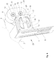
- connection piece 6 With the protective tube 7, the connecting piece 6 is connected by positive and positive connection.
- the connecting piece 6 has a bend 21, on which the stop 5 is fixed. From the connection piece 6 fixed to the protective tube 7 by a connection 26, the area for fastening the connecting piece 6 via the connection 26 to the protective tube 7 has been enlarged by using a bevel 27.
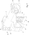
- the device is after FIG. 7 completed by the surrounding housing 2. It is clear that there is a change in the position of the protective tube 7 with the guide pieces 23, 24 from the rest position in the translational direction within the housing 2 by the longitudinal passage 13 in the housing 2 upon impact of a force on the stop 5. By applying the force on the stop 5, the tension spring element 19 is pulled apart and can thereby easily absorb the forces of the door leaf occurring in the final phase of the opening process.
- FIG. 8 a modified type of Endlagendämpfungs Republic 1 is shown in a further preferred embodiment.
- the housing 2 is identical, with only the tension spring element 19 has not been posted on the fortifications 29. Rather, the housing terminations are performed in a form that brings an even easier and more efficient storage or assembly with it.
- the housing 2 is fastened via fasteners 43 to the substantially horizontal sections of the guide rails or the like.
- the Tension spring element 19 is equipped on both sides for structure-borne noise reduction with damping measures.
- the end-side design of the housing 2 with a closure piece 36 can the FIG. 10 be removed.
- the end piece 36 is formed so that it rests against edges of the housing 2 and at the same time has bends 39 which engage in the housing 2.
- a secure fit and secure placement of the end pieces 36 are achieved.
- a rubber element 35 whose outer surface is provided with a disc 34.
- a nut 33 is tightened, which is screwed onto a connecting element 32 which is provided with a thread 40.
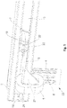
- FIG. 11 Through the sectional view to FIG. 11 This embodiment can still be clarified, wherein the connecting element 32 with a lateral clearance and air with respect to a bore 25, the end piece 36 penetrates.
- the part of the connecting element 32 which dips within the housing 2, has a bore 41, in which preferably an eyelet 38 is hooked into a differently shaped end of the tension spring element 19.
- the design of this attachment of the tension spring element 19 is designed so that no contact with parts of the housing 2 can take place, characterized a body sound decoupling is achieved to a large extent.
- the sectional view after FIG. 11 shows the tension spring element 19 in a loaded or partially loaded position, wherein the individual turns of the tension spring element 19 have been pulled apart.
- the representation of the FIG. 11 can be seen that a guide piece 42 has left in connection with the protective tube 7, the end position in the region of the end piece 36. By the guide pieces 24, 42, 23 a clean guidance of the protective tube 7 is achieved within the housing 2.
- FIG. 10 shows the tension spring element 19 in a partially loaded position, wherein in the longitudinal passage 13 of the housing 2, the connector 6 can come to outside of the housing 2.
- threaded holes 37 are still included, can be introduced via the screw 30.
- Such a connection shows the FIG. 9 , in which the attachment 43 is made with its angled portion 14 against the end piece 36.
- the connection between the bend 14 and the end piece 36 is achieved via the screw 30.
- 14 adjusting holes 31 have been inserted within the bend. So that the structure-borne noise decoupling can also retain its function with attached attachments 43, bores 25 are contained within the bends 14 and are so large that here too the rubber element 35 can pass with play.
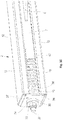
- FIG. 12 shows again in an exploded view the components contained within the housing 2 and how they are functionally connected to the fasteners 43.
- the protective tube 7 is equipped on the left side with the guide piece 42, wherein on the circumference of the protective tube 7, the connecting piece 6 has been fixed non-positively and positively with the cantilevered stop 5.
- the tension spring element 19 is included within the skirt tube 7, the tension spring element 19 is included.
- the connecting element 32 On the eyelet 28, the connecting element 32 has been attached.
- the guide piece 23 with the bore 25 thus allows the connecting element 32 to pass with all-round great play and to penetrate the rubber element 35 and the disk 34 in order to be secured by the nut 33.
- the fixing takes place against the end piece 36.
- the end pieces 36 are inserted end into the housing 2 and are attached even with the fasteners 43 on a substantially horizontal extension of a guide rail or the like.
- the cushioning 1 can also be regarded as a safety device, for example, if the end position of the control of the door fails, or if the force applied to the door leaf manual forces in the open position are too large.
Landscapes
- Closing And Opening Devices For Wings, And Checks For Wings (AREA)
- Operating, Guiding And Securing Of Roll- Type Closing Members (AREA)
- Vibration Dampers (AREA)
- Vibration Prevention Devices (AREA)
Priority Applications (1)
| Application Number | Priority Date | Filing Date | Title |
|---|---|---|---|
| PL16151469T PL3045643T3 (pl) | 2015-01-16 | 2016-01-15 | Skrzydło bramy |
Applications Claiming Priority (1)
| Application Number | Priority Date | Filing Date | Title |
|---|---|---|---|
| DE102015100617.0A DE102015100617B4 (de) | 2015-01-16 | 2015-01-16 | Torblatt |
Publications (2)
| Publication Number | Publication Date |
|---|---|
| EP3045643A1 EP3045643A1 (de) | 2016-07-20 |
| EP3045643B1 true EP3045643B1 (de) | 2019-01-02 |
Family
ID=55173796
Family Applications (1)
| Application Number | Title | Priority Date | Filing Date |
|---|---|---|---|
| EP16151469.0A Active EP3045643B1 (de) | 2015-01-16 | 2016-01-15 | Torblatt |
Country Status (5)
| Country | Link |
|---|---|
| EP (1) | EP3045643B1 (pl) |
| DE (1) | DE102015100617B4 (pl) |
| DK (1) | DK3045643T3 (pl) |
| ES (1) | ES2718741T3 (pl) |
| PL (1) | PL3045643T3 (pl) |
Families Citing this family (3)
| Publication number | Priority date | Publication date | Assignee | Title |
|---|---|---|---|---|
| DE102018108217A1 (de) | 2018-04-06 | 2019-10-10 | Alpha Deuren International Bv | Endlagenspeichervorrichtung sowie ein Tor mit einer Endlagenspeichervorrichtung |
| DE102018129581B4 (de) | 2018-11-23 | 2023-08-03 | Alpha Deuren International Bv | Hilfsantrieb für ein motorisch angetriebenes Torblatt, sowie Tor mit einem Hilfsantrieb |
| DE102019131119B4 (de) * | 2019-11-18 | 2025-07-03 | Alpha Deuren International Bv | Hilfsantrieb mit Dämpfungseinrichtung für ein ortsveränderbares Torblatt |
Family Cites Families (7)
| Publication number | Priority date | Publication date | Assignee | Title |
|---|---|---|---|---|
| DE7540330U (de) * | 1975-12-18 | 1976-08-19 | Ing. Lang & Menke Gmbh, 5870 Hemer | Bremseinrichtung fuer schwingtore |
| DE3206813C1 (de) * | 1982-02-25 | 1983-11-17 | Döring, Erich, 9442 Berneck, St. Gallen | Garagentor mit einer Tor-Fangvorrichtung |
| LU90195B1 (de) | 1998-01-15 | 1999-07-16 | Wurth Paul Sa | Abstichrinne fuer eine Eisenschmelze |
| EP1076144B1 (de) * | 1999-08-12 | 2004-05-26 | Johann Henkenjohann | Lamellentor |
| LU90915B1 (de) * | 2002-04-29 | 2003-10-30 | Pettinger S A R L | Sektionaltor |
| DE102004029990B4 (de) * | 2004-06-21 | 2008-01-17 | Bosch Rexroth Pneumatics Gmbh | Kolben-Zylinder-Einheit |
| DE202005006255U1 (de) * | 2005-04-19 | 2006-08-31 | Hörmann KG Antriebstechnik | Kraftbeätigtes Tor sowie dafür verwendbarer Torantrieb |
-
2015
- 2015-01-16 DE DE102015100617.0A patent/DE102015100617B4/de active Active
-
2016
- 2016-01-15 DK DK16151469.0T patent/DK3045643T3/en active
- 2016-01-15 EP EP16151469.0A patent/EP3045643B1/de active Active
- 2016-01-15 PL PL16151469T patent/PL3045643T3/pl unknown
- 2016-01-15 ES ES16151469T patent/ES2718741T3/es active Active
Non-Patent Citations (1)
| Title |
|---|
| None * |
Also Published As
| Publication number | Publication date |
|---|---|
| PL3045643T3 (pl) | 2019-08-30 |
| DK3045643T3 (en) | 2019-04-15 |
| ES2718741T3 (es) | 2019-07-04 |
| EP3045643A1 (de) | 2016-07-20 |
| DE102015100617B4 (de) | 2021-03-04 |
| DE102015100617A1 (de) | 2016-07-21 |
Similar Documents
| Publication | Publication Date | Title |
|---|---|---|
| EP2050907B1 (de) | Dämpfungs- und Einziehvorrichtung | |
| EP1247930B1 (de) | Vorrichtung zur Arretierung von in Schienen geführten Laufwerken | |
| EP2333218B1 (de) | Einrichtung zum Dämpfen der Relativbewegung bewegter Vorrichtungsteile, insbesondere von Schiebetüren | |
| EP2617336B1 (de) | Duschabtrennung | |
| DE102009042486A1 (de) | Schiebetür | |
| DE2917797A1 (de) | Einklemmsicherung fuer selbsttaetig oeffnende und schliessende tueren | |
| EP3199078B1 (de) | Duschabtrennung mit einer durch eine feder-dämpfer-einheit aktiv in die endstellungen bewegbaren schiebetür | |
| DE202008014529U1 (de) | Führungsvorrichtung für Schiebetüren | |
| EP3235983A1 (de) | Schiebetüranlage und schienenvorrichtung | |
| EP3045643B1 (de) | Torblatt | |
| DE102011011113A1 (de) | Rahmensystem eines Partikelschutzgitters | |
| DE102020102023A1 (de) | Schiebetürbeschlag und Verfahren zum Bewegen einer Steuereinrichtung | |
| EP3763911B1 (de) | Führungsschienenvorrichtung für ein rolltor oder ein rollgitter | |
| DE202018101882U1 (de) | Endlagendämpfungsvorrichtung | |
| EP3656958B1 (de) | Hilfsantrieb mit dämpfungseinrichtung für ein motorisch angetriebenes torblatt, sowie ein tor, dessen torblatt mit einem hilfsantrieb, der eine dämpfungseinrichtung beinhaltet, ausgestattet ist | |
| EP2366858A2 (de) | Vorrichtung zum Verschliessen einer Öffnung | |
| DE102011000295A1 (de) | Vorrichtung zum automatischen Schließen oder Öffnen einer Schiebetür | |
| DE102008047757B4 (de) | Vorrichtung zum Verschließen einer Öffnung | |
| DE202007013802U1 (de) | Einblatt-Überkopftor sowie Vorspanneinrichtung hierfür | |
| EP0495498B1 (de) | Aufnahmevorrichtung für den Endbereich einer Laufrollen-Führungsschiene eines Torblattes | |
| DE19501097C2 (de) | Kipptor | |
| EP3680445A1 (de) | Sicherheitslaufprofil, sowie ortsveränderbares torblatt mit einem sicherheitsprofil | |
| DE102011107961B4 (de) | Tragsystem für eine Schiebetür | |
| EP2511463A1 (de) | Fenster, Tür oder dergleichen mit einer Dämpfereinrichtung | |
| DE8029280U1 (de) | Garagenschwingtor |
Legal Events
| Date | Code | Title | Description |
|---|---|---|---|
| PUAI | Public reference made under article 153(3) epc to a published international application that has entered the european phase |
Free format text: ORIGINAL CODE: 0009012 |
|
| AK | Designated contracting states |
Kind code of ref document: A1 Designated state(s): AL AT BE BG CH CY CZ DE DK EE ES FI FR GB GR HR HU IE IS IT LI LT LU LV MC MK MT NL NO PL PT RO RS SE SI SK SM TR |
|
| AX | Request for extension of the european patent |
Extension state: BA ME |
|
| STAA | Information on the status of an ep patent application or granted ep patent |
Free format text: STATUS: REQUEST FOR EXAMINATION WAS MADE |
|
| 17P | Request for examination filed |
Effective date: 20170120 |
|
| RBV | Designated contracting states (corrected) |
Designated state(s): AL AT BE BG CH CY CZ DE DK EE ES FI FR GB GR HR HU IE IS IT LI LT LU LV MC MK MT NL NO PL PT RO RS SE SI SK SM TR |
|
| STAA | Information on the status of an ep patent application or granted ep patent |
Free format text: STATUS: EXAMINATION IS IN PROGRESS |
|
| 17Q | First examination report despatched |
Effective date: 20180201 |
|
| GRAP | Despatch of communication of intention to grant a patent |
Free format text: ORIGINAL CODE: EPIDOSNIGR1 |
|
| STAA | Information on the status of an ep patent application or granted ep patent |
Free format text: STATUS: GRANT OF PATENT IS INTENDED |
|
| INTG | Intention to grant announced |
Effective date: 20180815 |
|
| GRAS | Grant fee paid |
Free format text: ORIGINAL CODE: EPIDOSNIGR3 |
|
| GRAA | (expected) grant |
Free format text: ORIGINAL CODE: 0009210 |
|
| STAA | Information on the status of an ep patent application or granted ep patent |
Free format text: STATUS: THE PATENT HAS BEEN GRANTED |
|
| AK | Designated contracting states |
Kind code of ref document: B1 Designated state(s): AL AT BE BG CH CY CZ DE DK EE ES FI FR GB GR HR HU IE IS IT LI LT LU LV MC MK MT NL NO PL PT RO RS SE SI SK SM TR |
|
| REG | Reference to a national code |
Ref country code: GB Ref legal event code: FG4D Free format text: NOT ENGLISH |
|
| REG | Reference to a national code |
Ref country code: CH Ref legal event code: EP Ref country code: AT Ref legal event code: REF Ref document number: 1084589 Country of ref document: AT Kind code of ref document: T Effective date: 20190115 |
|
| REG | Reference to a national code |
Ref country code: IE Ref legal event code: FG4D Free format text: LANGUAGE OF EP DOCUMENT: GERMAN |
|
| REG | Reference to a national code |
Ref country code: DE Ref legal event code: R096 Ref document number: 502016003021 Country of ref document: DE |
|
| REG | Reference to a national code |
Ref country code: NL Ref legal event code: FP |
|
| REG | Reference to a national code |
Ref country code: SE Ref legal event code: TRGR |
|
| REG | Reference to a national code |
Ref country code: DK Ref legal event code: T3 Effective date: 20190408 |
|
| REG | Reference to a national code |
Ref country code: LT Ref legal event code: MG4D |
|
| REG | Reference to a national code |
Ref country code: ES Ref legal event code: FG2A Ref document number: 2718741 Country of ref document: ES Kind code of ref document: T3 Effective date: 20190704 |
|
| PG25 | Lapsed in a contracting state [announced via postgrant information from national office to epo] |
Ref country code: PT Free format text: LAPSE BECAUSE OF FAILURE TO SUBMIT A TRANSLATION OF THE DESCRIPTION OR TO PAY THE FEE WITHIN THE PRESCRIBED TIME-LIMIT Effective date: 20190502 Ref country code: LT Free format text: LAPSE BECAUSE OF FAILURE TO SUBMIT A TRANSLATION OF THE DESCRIPTION OR TO PAY THE FEE WITHIN THE PRESCRIBED TIME-LIMIT Effective date: 20190102 Ref country code: NO Free format text: LAPSE BECAUSE OF FAILURE TO SUBMIT A TRANSLATION OF THE DESCRIPTION OR TO PAY THE FEE WITHIN THE PRESCRIBED TIME-LIMIT Effective date: 20190402 Ref country code: FI Free format text: LAPSE BECAUSE OF FAILURE TO SUBMIT A TRANSLATION OF THE DESCRIPTION OR TO PAY THE FEE WITHIN THE PRESCRIBED TIME-LIMIT Effective date: 20190102 |
|
| PG25 | Lapsed in a contracting state [announced via postgrant information from national office to epo] |
Ref country code: IS Free format text: LAPSE BECAUSE OF FAILURE TO SUBMIT A TRANSLATION OF THE DESCRIPTION OR TO PAY THE FEE WITHIN THE PRESCRIBED TIME-LIMIT Effective date: 20190502 Ref country code: BG Free format text: LAPSE BECAUSE OF FAILURE TO SUBMIT A TRANSLATION OF THE DESCRIPTION OR TO PAY THE FEE WITHIN THE PRESCRIBED TIME-LIMIT Effective date: 20190402 Ref country code: RS Free format text: LAPSE BECAUSE OF FAILURE TO SUBMIT A TRANSLATION OF THE DESCRIPTION OR TO PAY THE FEE WITHIN THE PRESCRIBED TIME-LIMIT Effective date: 20190102 Ref country code: HR Free format text: LAPSE BECAUSE OF FAILURE TO SUBMIT A TRANSLATION OF THE DESCRIPTION OR TO PAY THE FEE WITHIN THE PRESCRIBED TIME-LIMIT Effective date: 20190102 Ref country code: LV Free format text: LAPSE BECAUSE OF FAILURE TO SUBMIT A TRANSLATION OF THE DESCRIPTION OR TO PAY THE FEE WITHIN THE PRESCRIBED TIME-LIMIT Effective date: 20190102 |
|
| REG | Reference to a national code |
Ref country code: CH Ref legal event code: PL |
|
| PG25 | Lapsed in a contracting state [announced via postgrant information from national office to epo] |
Ref country code: LU Free format text: LAPSE BECAUSE OF NON-PAYMENT OF DUE FEES Effective date: 20190115 |
|
| REG | Reference to a national code |
Ref country code: DE Ref legal event code: R097 Ref document number: 502016003021 Country of ref document: DE |
|
| REG | Reference to a national code |
Ref country code: IE Ref legal event code: MM4A |
|
| PG25 | Lapsed in a contracting state [announced via postgrant information from national office to epo] |
Ref country code: CZ Free format text: LAPSE BECAUSE OF FAILURE TO SUBMIT A TRANSLATION OF THE DESCRIPTION OR TO PAY THE FEE WITHIN THE PRESCRIBED TIME-LIMIT Effective date: 20190102 Ref country code: SK Free format text: LAPSE BECAUSE OF FAILURE TO SUBMIT A TRANSLATION OF THE DESCRIPTION OR TO PAY THE FEE WITHIN THE PRESCRIBED TIME-LIMIT Effective date: 20190102 Ref country code: MC Free format text: LAPSE BECAUSE OF FAILURE TO SUBMIT A TRANSLATION OF THE DESCRIPTION OR TO PAY THE FEE WITHIN THE PRESCRIBED TIME-LIMIT Effective date: 20190102 Ref country code: AL Free format text: LAPSE BECAUSE OF FAILURE TO SUBMIT A TRANSLATION OF THE DESCRIPTION OR TO PAY THE FEE WITHIN THE PRESCRIBED TIME-LIMIT Effective date: 20190102 Ref country code: EE Free format text: LAPSE BECAUSE OF FAILURE TO SUBMIT A TRANSLATION OF THE DESCRIPTION OR TO PAY THE FEE WITHIN THE PRESCRIBED TIME-LIMIT Effective date: 20190102 Ref country code: RO Free format text: LAPSE BECAUSE OF FAILURE TO SUBMIT A TRANSLATION OF THE DESCRIPTION OR TO PAY THE FEE WITHIN THE PRESCRIBED TIME-LIMIT Effective date: 20190102 Ref country code: IT Free format text: LAPSE BECAUSE OF FAILURE TO SUBMIT A TRANSLATION OF THE DESCRIPTION OR TO PAY THE FEE WITHIN THE PRESCRIBED TIME-LIMIT Effective date: 20190102 |
|
| PLBE | No opposition filed within time limit |
Free format text: ORIGINAL CODE: 0009261 |
|
| STAA | Information on the status of an ep patent application or granted ep patent |
Free format text: STATUS: NO OPPOSITION FILED WITHIN TIME LIMIT |
|
| PG25 | Lapsed in a contracting state [announced via postgrant information from national office to epo] |
Ref country code: SM Free format text: LAPSE BECAUSE OF FAILURE TO SUBMIT A TRANSLATION OF THE DESCRIPTION OR TO PAY THE FEE WITHIN THE PRESCRIBED TIME-LIMIT Effective date: 20190102 |
|
| 26N | No opposition filed |
Effective date: 20191003 |
|
| PG25 | Lapsed in a contracting state [announced via postgrant information from national office to epo] |
Ref country code: LI Free format text: LAPSE BECAUSE OF NON-PAYMENT OF DUE FEES Effective date: 20190131 Ref country code: CH Free format text: LAPSE BECAUSE OF NON-PAYMENT OF DUE FEES Effective date: 20190131 |
|
| PG25 | Lapsed in a contracting state [announced via postgrant information from national office to epo] |
Ref country code: IE Free format text: LAPSE BECAUSE OF NON-PAYMENT OF DUE FEES Effective date: 20190115 |
|
| PG25 | Lapsed in a contracting state [announced via postgrant information from national office to epo] |
Ref country code: SI Free format text: LAPSE BECAUSE OF FAILURE TO SUBMIT A TRANSLATION OF THE DESCRIPTION OR TO PAY THE FEE WITHIN THE PRESCRIBED TIME-LIMIT Effective date: 20190102 |
|
| PG25 | Lapsed in a contracting state [announced via postgrant information from national office to epo] |
Ref country code: TR Free format text: LAPSE BECAUSE OF FAILURE TO SUBMIT A TRANSLATION OF THE DESCRIPTION OR TO PAY THE FEE WITHIN THE PRESCRIBED TIME-LIMIT Effective date: 20190102 |
|
| PG25 | Lapsed in a contracting state [announced via postgrant information from national office to epo] |
Ref country code: MT Free format text: LAPSE BECAUSE OF FAILURE TO SUBMIT A TRANSLATION OF THE DESCRIPTION OR TO PAY THE FEE WITHIN THE PRESCRIBED TIME-LIMIT Effective date: 20190102 |
|
| PG25 | Lapsed in a contracting state [announced via postgrant information from national office to epo] |
Ref country code: CY Free format text: LAPSE BECAUSE OF FAILURE TO SUBMIT A TRANSLATION OF THE DESCRIPTION OR TO PAY THE FEE WITHIN THE PRESCRIBED TIME-LIMIT Effective date: 20190102 |
|
| PG25 | Lapsed in a contracting state [announced via postgrant information from national office to epo] |
Ref country code: GR Free format text: LAPSE BECAUSE OF FAILURE TO SUBMIT A TRANSLATION OF THE DESCRIPTION OR TO PAY THE FEE WITHIN THE PRESCRIBED TIME-LIMIT Effective date: 20190102 |
|
| PG25 | Lapsed in a contracting state [announced via postgrant information from national office to epo] |
Ref country code: HU Free format text: LAPSE BECAUSE OF FAILURE TO SUBMIT A TRANSLATION OF THE DESCRIPTION OR TO PAY THE FEE WITHIN THE PRESCRIBED TIME-LIMIT; INVALID AB INITIO Effective date: 20160115 |
|
| REG | Reference to a national code |
Ref country code: AT Ref legal event code: MM01 Ref document number: 1084589 Country of ref document: AT Kind code of ref document: T Effective date: 20210115 |
|
| PG25 | Lapsed in a contracting state [announced via postgrant information from national office to epo] |
Ref country code: AT Free format text: LAPSE BECAUSE OF NON-PAYMENT OF DUE FEES Effective date: 20210115 |
|
| PG25 | Lapsed in a contracting state [announced via postgrant information from national office to epo] |
Ref country code: MK Free format text: LAPSE BECAUSE OF FAILURE TO SUBMIT A TRANSLATION OF THE DESCRIPTION OR TO PAY THE FEE WITHIN THE PRESCRIBED TIME-LIMIT Effective date: 20190102 |
|
| PGFP | Annual fee paid to national office [announced via postgrant information from national office to epo] |
Ref country code: PL Payment date: 20251231 Year of fee payment: 11 |
|
| PGFP | Annual fee paid to national office [announced via postgrant information from national office to epo] |
Ref country code: NL Payment date: 20260121 Year of fee payment: 11 |
|
| PGFP | Annual fee paid to national office [announced via postgrant information from national office to epo] |
Ref country code: SE Payment date: 20260121 Year of fee payment: 11 |
|
| PGFP | Annual fee paid to national office [announced via postgrant information from national office to epo] |
Ref country code: GB Payment date: 20260123 Year of fee payment: 11 |
|
| PGFP | Annual fee paid to national office [announced via postgrant information from national office to epo] |
Ref country code: ES Payment date: 20260227 Year of fee payment: 11 |
|
| PGFP | Annual fee paid to national office [announced via postgrant information from national office to epo] |
Ref country code: DK Payment date: 20260126 Year of fee payment: 11 Ref country code: DE Payment date: 20260121 Year of fee payment: 11 |
|
| PGFP | Annual fee paid to national office [announced via postgrant information from national office to epo] |
Ref country code: BE Payment date: 20260121 Year of fee payment: 11 |
|
| PGFP | Annual fee paid to national office [announced via postgrant information from national office to epo] |
Ref country code: FR Payment date: 20260123 Year of fee payment: 11 |