EP2182154B1 - Führungsvorrichtung für Schiebetüren - Google Patents
Führungsvorrichtung für Schiebetüren Download PDFInfo
- Publication number
- EP2182154B1 EP2182154B1 EP09169612A EP09169612A EP2182154B1 EP 2182154 B1 EP2182154 B1 EP 2182154B1 EP 09169612 A EP09169612 A EP 09169612A EP 09169612 A EP09169612 A EP 09169612A EP 2182154 B1 EP2182154 B1 EP 2182154B1
- Authority
- EP
- European Patent Office
- Prior art keywords
- housing
- sliding door
- sliding doors
- plunger
- damper
- Prior art date
- Legal status (The legal status is an assumption and is not a legal conclusion. Google has not performed a legal analysis and makes no representation as to the accuracy of the status listed.)
- Not-in-force
Links
- 239000012530 fluid Substances 0.000 claims description 5
- 238000013016 damping Methods 0.000 description 14
- 239000000872 buffer Substances 0.000 description 3
- 239000006096 absorbing agent Substances 0.000 description 2
- 238000000034 method Methods 0.000 description 2
- 230000035939 shock Effects 0.000 description 2
- 230000015572 biosynthetic process Effects 0.000 description 1
- 238000010276 construction Methods 0.000 description 1
- 230000000994 depressogenic effect Effects 0.000 description 1
- 239000000463 material Substances 0.000 description 1
- 238000009420 retrofitting Methods 0.000 description 1
Images

Classifications
-
- E—FIXED CONSTRUCTIONS
- E05—LOCKS; KEYS; WINDOW OR DOOR FITTINGS; SAFES
- E05F—DEVICES FOR MOVING WINGS INTO OPEN OR CLOSED POSITION; CHECKS FOR WINGS; WING FITTINGS NOT OTHERWISE PROVIDED FOR, CONCERNED WITH THE FUNCTIONING OF THE WING
- E05F5/00—Braking devices, e.g. checks; Stops; Buffers
- E05F5/003—Braking devices, e.g. checks; Stops; Buffers for sliding wings
-
- E—FIXED CONSTRUCTIONS
- E05—LOCKS; KEYS; WINDOW OR DOOR FITTINGS; SAFES
- E05D—HINGES OR SUSPENSION DEVICES FOR DOORS, WINDOWS OR WINGS
- E05D15/00—Suspension arrangements for wings
- E05D15/06—Suspension arrangements for wings for wings sliding horizontally more or less in their own plane
- E05D15/08—Suspension arrangements for wings for wings sliding horizontally more or less in their own plane consisting of two or more independent parts movable each in its own guides
-
- E—FIXED CONSTRUCTIONS
- E05—LOCKS; KEYS; WINDOW OR DOOR FITTINGS; SAFES
- E05F—DEVICES FOR MOVING WINGS INTO OPEN OR CLOSED POSITION; CHECKS FOR WINGS; WING FITTINGS NOT OTHERWISE PROVIDED FOR, CONCERNED WITH THE FUNCTIONING OF THE WING
- E05F17/00—Special devices for shifting a plurality of wings operated simultaneously
- E05F2017/005—Special devices for shifting a plurality of wings operated simultaneously for sliding wings
- E05F2017/007—Special devices for shifting a plurality of wings operated simultaneously for sliding wings with means for interlocking the wings
-
- E—FIXED CONSTRUCTIONS
- E05—LOCKS; KEYS; WINDOW OR DOOR FITTINGS; SAFES
- E05Y—INDEXING SCHEME ASSOCIATED WITH SUBCLASSES E05D AND E05F, RELATING TO CONSTRUCTION ELEMENTS, ELECTRIC CONTROL, POWER SUPPLY, POWER SIGNAL OR TRANSMISSION, USER INTERFACES, MOUNTING OR COUPLING, DETAILS, ACCESSORIES, AUXILIARY OPERATIONS NOT OTHERWISE PROVIDED FOR, APPLICATION THEREOF
- E05Y2201/00—Constructional elements; Accessories therefor
- E05Y2201/20—Brakes; Disengaging means; Holders; Stops; Valves; Accessories therefor
- E05Y2201/21—Brakes
-
- E—FIXED CONSTRUCTIONS
- E05—LOCKS; KEYS; WINDOW OR DOOR FITTINGS; SAFES
- E05Y—INDEXING SCHEME ASSOCIATED WITH SUBCLASSES E05D AND E05F, RELATING TO CONSTRUCTION ELEMENTS, ELECTRIC CONTROL, POWER SUPPLY, POWER SIGNAL OR TRANSMISSION, USER INTERFACES, MOUNTING OR COUPLING, DETAILS, ACCESSORIES, AUXILIARY OPERATIONS NOT OTHERWISE PROVIDED FOR, APPLICATION THEREOF
- E05Y2201/00—Constructional elements; Accessories therefor
- E05Y2201/20—Brakes; Disengaging means; Holders; Stops; Valves; Accessories therefor
- E05Y2201/224—Stops
-
- E—FIXED CONSTRUCTIONS
- E05—LOCKS; KEYS; WINDOW OR DOOR FITTINGS; SAFES
- E05Y—INDEXING SCHEME ASSOCIATED WITH SUBCLASSES E05D AND E05F, RELATING TO CONSTRUCTION ELEMENTS, ELECTRIC CONTROL, POWER SUPPLY, POWER SIGNAL OR TRANSMISSION, USER INTERFACES, MOUNTING OR COUPLING, DETAILS, ACCESSORIES, AUXILIARY OPERATIONS NOT OTHERWISE PROVIDED FOR, APPLICATION THEREOF
- E05Y2201/00—Constructional elements; Accessories therefor
- E05Y2201/20—Brakes; Disengaging means; Holders; Stops; Valves; Accessories therefor
- E05Y2201/252—Type of friction
- E05Y2201/254—Fluid or viscous friction
- E05Y2201/256—Fluid or viscous friction with pistons or vanes
-
- E—FIXED CONSTRUCTIONS
- E05—LOCKS; KEYS; WINDOW OR DOOR FITTINGS; SAFES
- E05Y—INDEXING SCHEME ASSOCIATED WITH SUBCLASSES E05D AND E05F, RELATING TO CONSTRUCTION ELEMENTS, ELECTRIC CONTROL, POWER SUPPLY, POWER SIGNAL OR TRANSMISSION, USER INTERFACES, MOUNTING OR COUPLING, DETAILS, ACCESSORIES, AUXILIARY OPERATIONS NOT OTHERWISE PROVIDED FOR, APPLICATION THEREOF
- E05Y2201/00—Constructional elements; Accessories therefor
- E05Y2201/20—Brakes; Disengaging means; Holders; Stops; Valves; Accessories therefor
- E05Y2201/262—Type of motion, e.g. braking
- E05Y2201/264—Type of motion, e.g. braking linear
-
- E—FIXED CONSTRUCTIONS
- E05—LOCKS; KEYS; WINDOW OR DOOR FITTINGS; SAFES
- E05Y—INDEXING SCHEME ASSOCIATED WITH SUBCLASSES E05D AND E05F, RELATING TO CONSTRUCTION ELEMENTS, ELECTRIC CONTROL, POWER SUPPLY, POWER SIGNAL OR TRANSMISSION, USER INTERFACES, MOUNTING OR COUPLING, DETAILS, ACCESSORIES, AUXILIARY OPERATIONS NOT OTHERWISE PROVIDED FOR, APPLICATION THEREOF
- E05Y2201/00—Constructional elements; Accessories therefor
- E05Y2201/60—Suspension or transmission members; Accessories therefor
- E05Y2201/622—Suspension or transmission members elements
- E05Y2201/64—Carriers
-
- E—FIXED CONSTRUCTIONS
- E05—LOCKS; KEYS; WINDOW OR DOOR FITTINGS; SAFES
- E05Y—INDEXING SCHEME ASSOCIATED WITH SUBCLASSES E05D AND E05F, RELATING TO CONSTRUCTION ELEMENTS, ELECTRIC CONTROL, POWER SUPPLY, POWER SIGNAL OR TRANSMISSION, USER INTERFACES, MOUNTING OR COUPLING, DETAILS, ACCESSORIES, AUXILIARY OPERATIONS NOT OTHERWISE PROVIDED FOR, APPLICATION THEREOF
- E05Y2600/00—Mounting or coupling arrangements for elements provided for in this subclass
- E05Y2600/40—Mounting location; Visibility of the elements
- E05Y2600/456—Mounting location; Visibility of the elements in or on a suspension member
-
- E—FIXED CONSTRUCTIONS
- E05—LOCKS; KEYS; WINDOW OR DOOR FITTINGS; SAFES
- E05Y—INDEXING SCHEME ASSOCIATED WITH SUBCLASSES E05D AND E05F, RELATING TO CONSTRUCTION ELEMENTS, ELECTRIC CONTROL, POWER SUPPLY, POWER SIGNAL OR TRANSMISSION, USER INTERFACES, MOUNTING OR COUPLING, DETAILS, ACCESSORIES, AUXILIARY OPERATIONS NOT OTHERWISE PROVIDED FOR, APPLICATION THEREOF
- E05Y2600/00—Mounting or coupling arrangements for elements provided for in this subclass
- E05Y2600/40—Mounting location; Visibility of the elements
- E05Y2600/46—Mounting location; Visibility of the elements in or on the wing
-
- E—FIXED CONSTRUCTIONS
- E05—LOCKS; KEYS; WINDOW OR DOOR FITTINGS; SAFES
- E05Y—INDEXING SCHEME ASSOCIATED WITH SUBCLASSES E05D AND E05F, RELATING TO CONSTRUCTION ELEMENTS, ELECTRIC CONTROL, POWER SUPPLY, POWER SIGNAL OR TRANSMISSION, USER INTERFACES, MOUNTING OR COUPLING, DETAILS, ACCESSORIES, AUXILIARY OPERATIONS NOT OTHERWISE PROVIDED FOR, APPLICATION THEREOF
- E05Y2800/00—Details, accessories and auxiliary operations not otherwise provided for
- E05Y2800/74—Specific positions
- E05Y2800/75—Specific positions intermediate
-
- E—FIXED CONSTRUCTIONS
- E05—LOCKS; KEYS; WINDOW OR DOOR FITTINGS; SAFES
- E05Y—INDEXING SCHEME ASSOCIATED WITH SUBCLASSES E05D AND E05F, RELATING TO CONSTRUCTION ELEMENTS, ELECTRIC CONTROL, POWER SUPPLY, POWER SIGNAL OR TRANSMISSION, USER INTERFACES, MOUNTING OR COUPLING, DETAILS, ACCESSORIES, AUXILIARY OPERATIONS NOT OTHERWISE PROVIDED FOR, APPLICATION THEREOF
- E05Y2900/00—Application of doors, windows, wings or fittings thereof
- E05Y2900/20—Application of doors, windows, wings or fittings thereof for furniture, e.g. cabinets
Definitions
- the present invention relates to a guide device for sliding doors, in particular for furniture, according to the preamble of claim 1.
- a damping device for sliding doors in which a driver can be coupled with a movable furniture part.
- the driver is coupled to the furniture part shortly before an end position and then braked in the movement, for which purpose an eddy-current brake is provided.
- the damping device can be coupled with a self-closing, so that the sliding door can be easily moved to the closed position. This results in the problem that the most heavy sliding doors can be moved in the opening direction to an end position and are braked relatively abruptly there, since no damping device is provided there.
- a sliding door which is mounted horizontally movable on a rail, wherein a shock absorber is provided on a furniture body.
- this shock absorber can cause deceleration, avoiding an abrupt stop.
- the GB 2 416 380 which discloses all features of the preamble of claim 1, discloses a fluid damper with a cylindrical housing in which a plunger is movably mounted.
- the plunger is biased by a spring in the extended position and can be retracted for damping in the housing.
- the housing can be mounted on doors or other moving components.
- the EP 1 700 985 a damper for sliding doors to avoid hitting the sliding doors.
- the guide device for braking an opening movement of a sliding door comprises a linear damper, which has a plunger which can be pushed into a housing.
- a sliding door can also be braked in the opening direction before reaching an end position in order to avoid a hard impact. This reduces the material load and avoids loud impact noises.
- the housing is connected via a holder with a sliding door and another sliding door forms a stop for the plunger.
- a sliding door For most sliding doors are used in furniture that are movable in the opening direction in a covering position, so that the still closed sliding door can serve as a stop. In particular, if three sliding doors are provided, a stop can be provided on the middle sliding door, which considerably simplifies the construction and assembly of the guiding device.
- a fitting plate with a roller On a sliding door, a fitting plate with a roller is fixed and the housing is mounted on the fitting plate.
- existing guide devices for sliding doors can be easily retrofitted with a linear damper.
- two projecting pins are provided for this purpose on the fitting plate and the holder has two openings which are penetrated by the pins.
- the pins are used in existing guide devices as a fastening device for sleeve-shaped rubber buffer. As a result, the linear damper can be retrofitted very easily.
- a linear damper for example, designed as a gas or fluid damper with a damper housing and a movable relative to the damper housing piston rod.
- Such fluid damper can cause a high damping force at high impact speeds, while at low speeds only a small damping force is present, as then threatens no hitting the sliding door at high speed.
- the plunger of the linear damper can be biased by a spring in an extended position, so that automatically a retraction of the plunger takes place in the starting position when the sliding door is closed again.
- the force of the spring is so dimensioned that the sliding door is not moved in the fully open end position by the plunger, but this remains in the depressed position. Only when the sliding door is closed, the plunger is then moved back into the extended position.
- an angle is provided for guiding a sliding door, in particular the middle sliding door, which engages over another sliding door, wherein the angle forms a stop for the plunger.
- the angle forms a stop for the plunger.
- the guide device comprises three sliding doors, wherein two of the sliding doors on the same plane are movably held on the rail. Most of the middle rail is mounted in a second level, so that the sliding doors can be moved to open in a covering position.
- a guide device 1 comprises three sliding doors 2, 3 and 4, which are mounted on a rail 5 with two tracks according to movable in two planes.
- the rail 5 is fixed to a furniture body 30, in particular a cabinet furniture.
- 5 damping devices 6, 7 and 8 are provided on the rail, which provide in a process of the sliding doors 2, 3 and 4 in the closed position for damping, in addition, a self-closing device may be provided.
- the damping devices 6, 7 and 8 may be formed as shown in the WO 2006/114352 is described.
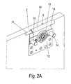
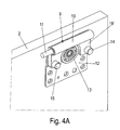
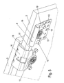
- a linear damper 9 with a housing 10 and a displaceably arranged to the housing 10 plunger 11 ( Fig. 2A and 2 B ).
- the housing 10 is connected via a holder 19 with a fitting plate 12, on which a roller 13 is rotatably mounted.
- a roller 13 is rotatably mounted on opposite sides of the roller 13 projecting pins 14 and 15 are provided, on which annular rubber buffers can be mounted.
- the holder 19 for the housing 10 has two protruding bolts 20 which are insertable into corresponding openings 21 on the fitting plate 12, so that the holder 19 is stably held on the fitting plate 12.
- the holder 19 can be formed integrally with the housing 10 or be connected by mechanical fastening means with this.
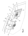
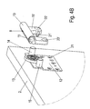
- FIG. 3 a stop position for the linear damper 9 is shown.
- the middle sliding door 3 has an angle 16, which can overlap one of the outer sliding doors 2 or 4 and on which a roller 17 is mounted.
- an end edge 18 of the angle 16 engages with the displaceably mounted plunger 11 and presses it into the housing 10.
- a linear damper 9 is provided, so that the opening movement is damped.
- the plunger 11 is biased by a spring in the housing 10 in the open position, wherein the force of the spring is so small that the central sliding door 3 is not moved in the maximum open position in the closed direction.
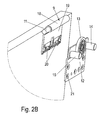
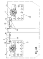
- FIGS. 4A and 4B a second embodiment of a linear damper 9 is shown, which is mounted on the fitting plate 12 on the outer sliding door 2.
- the housing 10 of the linear damper 9 is fixed on the fitting plate 12 via a modified holder 19 ', the holder 19' having two spaced-apart openings 20 ', which are designed such that they are attached to the pins 14 and 15 on the fitting plate 12 can be.
- the holder 19 ' can be clamped to the fitting plate 12, so that no further fastening means are necessary.
- the holder 19 'pins 21' are formed, which can be inserted into corresponding openings 21 on the fitting plate 12.
- the linear damper 9 can be mounted without tools on the fitting plate 12, especially when retrofitting.
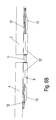
- FIGS. 6A and 6B a not erfindungdins embodiment of a linear damper 9 is shown, which is mounted on a housing 10 'on an outer sliding door 4.
- the linear damper 9 comprises a housing 10 ', on which a protruding plate 25 is provided, are provided on the openings 26 for screws.
- the housing 10 'of the linear damper 9 is mounted so that it is aligned with a side edge of the outer sliding door 4 frontally. From the housing 10 ', the plunger 11 protrudes to the side.
- the linear damper 9 can be operated.
- a stop 10 ' is mounted on the outer sliding door 2, which has the shape of the housing 10', but no plunger 11 identifies.
- the stop 10 ' also has a protruding plate 25 which is fixed by screws on the outer sliding door 2.
- the stopper 10 ' is designed to be flush with the outer sliding door 2 on the edge side towards the plunger 11, so that when the outer sliding doors 2 and 4 move together, the plunger 11 is pressed into the housing 10'.
- a linear damper 9 is moved in the housing 10 'for damping.
- a linear damper 9 known fluid damper can be used, in which a damper housing is provided, in which an oil is arranged, which is moved by the movement of a piston in the damper housing.
- the piston can be moved via a piston rod, which is coupled to the plunger or the housing 10, 10 '.
- housing 10 and 10 may be provided a spring with a small spring force, which moves the plunger 11 against the force of the linear damper 9 in the extended position.
- three sliding doors 2, 3 and 4 are provided, which are damped by a linear damper 9 when moving in the opening direction before the maximum opening position. It is of course also possible to provide only two sliding doors 2 and 3 or more than three sliding doors 2, 3 and 4 on the guide device. In addition, the number of levels for the sliding doors 2, 3 and 4 of two can be increased even more, especially if several sliding doors are to be moved.
Landscapes
- Engineering & Computer Science (AREA)
- Mechanical Engineering (AREA)
- Wing Frames And Configurations (AREA)
- Special Wing (AREA)
- Power-Operated Mechanisms For Wings (AREA)
- Closing And Opening Devices For Wings, And Checks For Wings (AREA)
- Auxiliary Devices For Machine Tools (AREA)
Description
- Die vorliegende Erfindung betrifft eine Führungsvorrichtung für Schiebetüren, insbesondere für Möbel, nach dem Oberbegriff des Anspruches 1.
- Aus der
WO 2006/114352 ist eine Dämpfungseinrichtung für Schiebetüren bekannt, bei der ein Mitnehmer mit einem bewegbaren Möbelteil koppelbar ist. Bei einer Schließbewegung wird kurz vor einer Endposition der Mitnehmer mit dem Möbelteil gekoppelt und dann in der Bewegung abgebremst, wofür eine Wirbelstrombremse vorgesehen ist. Die Dämpfungseinrichtung kann dabei mit einem Selbsteinzug gekoppelt-sein, so dass die Schiebetür komfortabel in die geschlossene Position bewegt werden kann. Dabei ergibt sich das Problem, dass die meist schweren Schiebetüren in Öffnungsrichtung bis zu einer Endstellung bewegt werden können und dort relativ abrupt abgebremst werden, da dort keine Dämpfungseinrichtung vorgesehen ist. - Aus der
DE 20 2006 017402 U ist eine Schiebetür bekannt, die an einer Schiene horizontal verfahrbar gelagert ist, wobei an einem Möbelkorpus ein Stoßdämpfer vorgesehen ist. Wenn die Schiebetür aus der Öffnungsstellung in die Schließstellung bewegt wird, kann dieser Stoßdämpfer für ein Abbremsen sorgen, was einen abrupten Anschlag vermeidet. - Die
GB 2 416 380 - Ferner offenbart die
EP 1 700 985 einen Dämpfer für Schiebtüren, um ein Anschlagen der Schiebetüren zu vermeiden. - Es ist daher Aufgabe der vorliegenden Erfindung, eine Führungsvorrichtung für Schiebetüren zu schaffen, die ein hartes Anschlagen einer Schiebetür bei einer Bewegung in Öffnungsrichtung vermeidet.
- Diese Aufgabe wird mit einer Führungsvorrichtung mit den Merkmalen des Anspruches 1 gelöst.
- Erfindungsgemäß umfasst die Führungsvorrichtung zum Abbremsen einer Öffnungsbewegung einer Schiebetür einen Lineardämpfer, der einen in ein Gehäuse einschiebbaren Stößel aufweist. Dadurch kann eine Schiebetür auch in Öffnungsrichtung vor Erreichen einer Endposition abgebremst werden, um ein hartes Anschlagen zu vermeiden. Dies verringert die Materialbelastung und vermeidet laute Anschlaggeräusche.
- Erfindungsgemäß ist das Gehäuse über einen Halter mit einer Schiebetür verbunden und eine andere Schiebetür bildet einen Anschlag für den Stößel aus. Denn meist werden Schiebetüren bei Möbeln eingesetzt, die in Öffnungsrichtung in eine sich überdeckende Position bewegbar sind, so dass die noch geschlossene Schiebetür als Anschlag dienen kann. Insbesondere wenn drei Schiebetüren vorgesehen sind, kann an der mittleren Schiebetür ein Anschlag bereitgestellt werden, was den Aufbau und die Montage der Führungsvorrichtung erheblich vereinfacht.
- An einer Schiebetür ist eine Beschlagplatte mit einer Laufrolle festgelegt und das Gehäuse ist an der Beschlagplatte montiert. Dadurch können bestehende Führungsvorrichtungen für Schiebetüren auf einfache Weise mit einem Lineardämpfer nachgerüstet werden. Erfindungsgemäß sind hierfür an der Beschlagplatte zwei hervorstehende Zapfen vorgesehen und der Halter weist zwei Öffnungen auf, die von den Zapfen durchgriffen sind. Die Zapfen werden bei vorhandenen Führungsvorrichtungen als Befestigungsvorrichtung für hülsenförmige Gummipuffer verwendet. Dadurch können die Lineardämpfer besonders einfach nachgerüstet werden.
- Vorzugsweise ist in dem Gehäuse ein Lineardämpfer beispielsweise ausgeführt als Gas- oder Fluiddämpfer mit einem Dämpfergehäuse und einer relativ zu dem Dämpfergehäuse bewegbaren Kolbenstange vorgesehen. Solche Fluiddämpfer können bei hohen Aufprallgeschwindigkeiten eine hohe Dämpfungskraft bewirken, während bei niedrigen Geschwindigkeiten nur eine geringe Dämpfungskraft vorhanden ist, da dann auch kein Anschlagen der Schiebetür mit großer Geschwindigkeit droht. Der Stößel des Lineardämpfers kann dabei durch eine Feder in eine ausgefahrene Position vorgespannt sein, so dass automatisch ein Herausfahren des Stößels in die Ausgangsposition erfolgt, wenn die Schiebetür wieder geschlossen wird. Dabei ist die Kraft der Feder so bemessen, dass die Schiebetür in der ganz geöffneten Endposition durch den Stößel nicht verfahren wird, sondern dieser in der eingedrückten Position verbleibt. Erst bei einem Schließen der Schiebetür wird dann der Stößel wieder in die ausgefahrene Position bewegt.
- Vorzugsweise ist zur Führung einer Schiebetür, insbesondere der mittleren Schiebetür, ein Winkel vorgesehen, der eine andere Schiebetür übergreift, wobei der Winkel einen Anschlag für den Stößel ausbildet. Dadurch muss für die Ausbildung eines Anschlages kein zusätzliches Bauteil montiert werden.
- Vorzugsweise umfasst die Führungsvorrichtung drei Schiebetüren, wobei zwei der Schiebetüren an der selben Ebene verfahrbar an der Schiene gehalten sind. Meist ist die mittlere Schiene in einer zweiten Ebene gelagert, so dass die Schiebetüren zum Öffnen in eine sich überdeckende Position verfahren werden können.
- Die Erfindung wird nachfolgend anhand mehrerer Ausführungsbeispiele mit Bezug auf die beigefügten Zeichnungen näher erläutert. Es zeigen:
- Figur 1
- eine Draufsicht auf eine erfindungsgemäße Führungsvor- richtung für Schiebetüren;
- Figuren 2A und 2B
- zwei Ansichten eines ersten Lineardämpfers der Führungs- vorrichtung der
Figur 1 ; - Figur 3
- eine perspektivische Ansicht des Lineardämpfers der
Figur 2 in der Anschlagposition; - Figuren 4A und 4B
- zwei Ansichten eines zweiten Lineardämpfers der erfin- dungsgemäßen Führungsvorrichtung;
- Figur 5
- eine perspektivische Ansicht des zweiten Lineardämpfers in der Anschlagposition; und
- Figuren 6A und 6B
- zwei Ansichten eines Lineardämpfers einer nicht erfin- dungsgemäßen Fühnmgsvorrichtung.
- Eine Führungsvorrichtung 1 umfasst drei Schiebetüren 2, 3 und 4, die an einer Schiene 5 mit zwei Laufbahnen entsprechend in zwei Ebenen verfahrbar gelagert sind. Die Schiene 5 ist an einem Möbelkorpus 30, insbesondere einem Schrankmöbel, festgelegt. Ferner sind an der Schiene 5 Dämpfungsvorrichtungen 6, 7 und 8 vorgesehen, die bei einem Verfahren der Schiebetüren 2, 3 und 4 in die geschlossene Position für eine Dämpfung sorgen, wobei zusätzlich eine Selbsteinzugsvorrichtung vorgesehen sein kann. Die Dämpfungsvorrichtungen 6, 7 und 8 können so ausgebildet sein, wie dies in der
WO 2006/114352 beschrieben ist. - Um bei einem Verfahren der Schiebetüren 2, 3 und 4 auch eine Dämpfung vorzunehmen, wenn diese in eine maximal geöffnete Position bewegt werden, bei denen sich die Schiebetüren 2 und 3 oder 3 und 4 überdecken, ist an der äußeren Schiebetür 2 ein Lineardämpfer 9 mit einem Gehäuse 10 und einem verschiebbar zu dem Gehäuse 10 angeordneten Stößel 11 vorgesehen (
Fig. 2A und2B ). Das Gehäuse 10 ist dabei über einen Halter 19 mit einer Beschlagplatte 12 verbunden, an der eine Laufrolle 13 drehbar gelagert ist. An gegenüberliegenden Seiten der Laufrolle 13 sind hervorstehende Zapfen 14 und 15 vorgesehen, an denen ringförmige Gummipuffer montiert werden können. Bei Einsatz eines Lineardämpfers mit dem Gehäuse 10 und dem Stößel 11 kann jedoch auf entsprechende Gummipuffer verzichtet werden. Der Halter 19 für das Gehäuse 10 weist zwei hervorstehende Bolzen 20 auf, die in entsprechende Öffnungen 21 an der Beschlagplatte 12 einfügbar sind, so dass der Halter 19 stabil an der Beschlagplatte 12 gehalten ist. Der Halter 19 kann dabei integral mit dem Gehäuse 10 ausgebildet sein oder durch mechanische Befestigungsmittel mit diesem verbunden sein. - In
Figur 3 ist eine Anschlagsposition für den Lineardämpfer 9 gezeigt. Die mittlere Schiebetür 3 weist einen Winkel 16 auf, der eine der äußeren Schiebetüren 2 oder 4 übergreifen kann und an dem eine Laufrolle 17 gelagert ist. Bei einer maximalen Öffnungsposition der mittleren Schiebetür 3 oder der äußeren Schiebetür 2 gelangt eine Stirnkante 18 des Winkels 16 in Eingriff mit dem verschiebbar gelagerten Stößel 11 und drückt diesen in das Gehäuse 10 ein. In dem Gehäuse 10 ist dabei ein Lineardämpfer 9 vorgesehen, so dass die Öffnungsbewegung gedämpft erfolgt. Der Stößel 11 ist dabei durch eine Feder in dem Gehäuse 10 in die geöffnete Position vorgespannt, wobei die Kraft der Feder so gering ist, dass die mittlere Schiebetür 3 in der maximal geöffneten Position nicht in die geschlossene Richtung bewegt wird. - In den
Figuren 4A und4B ist eine zweite Ausführungsform eines Lineardämpfers 9 gezeigt, der an der Beschlagplatte 12 an der äußeren Schiebetür 2 montiert ist. Das Gehäuse 10 des Lineardämpfers 9 ist über einen modifizierten Halter 19' an der Beschlagplatte 12 festgelegt, wobei der Halter 19' zwei voneinander beabstandete Öffnungen 20' aufweist, die so ausgebildet sind, dass sie auf die Zapfen 14 und 15 an der Beschlagplatte 12 aufgesteckt werden können. Dabei kann der Halter 19' klemmend an der Beschlagplatte 12 festgelegt werden, so dass keine weiteren Befestigungsmittel notwendig sind. Ferner sind an dem Halter 19' Zapfen 21' ausgebildet, die in entsprechende Öffnungen 21 an der Beschlagplatte 12 eingefügt werden können. Dadurch kann der Lineardämpfer 9 werkzeugfrei an der Beschlagplatte 12 montiert werden, insbesondere auch bei einer Nachrüstung. - In den
Figuren 6A und6B ist ein nicht erfindungdgemäßes Ausführungsbeispiel eines Lineardämpfers 9 gezeigt, der an einem Gehäuse 10' an einer äußeren Schiebetür 4 montiert ist. Der Lineardämpfer 9 umfasst ein Gehäuse 10', an dem eine hervorstehende Platte 25 vorgesehen ist, an den Öffnungen 26 für Schrauben vorgesehen sind. Das Gehäuse 10' des Lineardämpfers 9 ist so montiert, dass es stirnseitig mit einer Seitenkante der äußeren Schiebetür 4 fluchtet. Von dem Gehäuse 10' steht der Stößel 11 zur Seite hin hervor. - In der maximalen Öffnungsposition der äußeren Schiebetür 2 oder der äußeren Schiebetür 4 kann der Lineardämpfer 9 betätigt werden. Hierfür ist an der äußeren Schiebetür 2 ein Anschlag 10' montiert, der die Form des Gehäuses 10' besitzt, aber keinen Stößel 11 ausweist. Der Anschlag 10' weist ebenfalls eine hervorstehende Platte 25 auf, die über Schrauben an der äußeren Schiebetür 2 festgelegt ist. Der Anschlag 10' ist dabei randseitig zu dem Stößel 11 hin gerichtet fluchtend mit der äußeren Schiebetür 2 ausgebildet, so dass beim Zusammenfahren der äußeren Schiebetüren 2 und 4 der Stößel 11 in das Gehäuse 10' eingedrückt wird. Auch hier wird ein Lineardämpfer 9 in dem Gehäuse 10' für eine Dämpfung bewegt.
- Als Lineardämpfer 9 können bekannte Fluiddämpfer eingesetzt werden, bei denen ein Dämpfergehäuse vorgesehen ist, in dem ein Öl angeordnet ist, das durch die Bewegung eines Kolbens in dem Dämpfergehäuse bewegt wird. Der Kolben kann über eine Kolbenstange verfahren werden, die mit dem Stößel oder dem Gehäuse 10, 10' gekoppelt ist.
- Ferner kann in dem Gehäuse 10 bzw. 10 eine Feder mit geringer Federkraft vorgesehen sein, die den Stößel 11 gegen die Kraft des Lineardämpfers 9 in die ausgefahrene Position bewegt.
- Bei der gezeigten Ausführungsform sind drei Schiebetüren 2, 3 und 4 vorgesehen, die bei Bewegung in Öffnungsrichtung vor der maximalen Öffnungsposition durch einen Lineardämpfer 9 gedämpft werden. Es ist natürlich auch möglich, nur zwei Schiebetüren 2 und 3 oder mehr als drei Schiebetüren 2, 3 und 4 an der Führungsvorrichtung vorzusehen. Zudem kann die Anzahl der Ebenen für die Schiebetüren 2, 3 und 4 von zwei noch erhöht werden, insbesondere wenn auch mehrere Schiebetüren verfahren werden sollen.
-
- 1
- Führungsvorrichtung
- 2
- Äußere Schiebetür
- 3
- Mittlere Schiebetür
- 4
- Äußere Schiebetür
- 5
- Schiene
- 6
- Dämpfungsvorrichtung
- 7
- Dämpfungsvorrichtung
- 8
- Dämpfungsvorrichtung
- 9
- Lineardämpfer
- 10
- Gehäuse
- 10'
- Gehäuse
- 11
- Stößel
- 12
- Beschlagplatte
- 13
- Laufrolle
- 14
- Zapfen
- 15
- Zapfen
- 16
- Winkel
- 17
- Laufrolle
- 18
- Stirnkante
- 19
- Halter
- 19'
- Halter
- 20
- Bolzen
- 20'
- Öffnungen
- 21
- Öffnung
- 21'
- Zapfen
- 25
- Platte
- 26
- Öffnungen
- 30
- Möbelkorpus
Claims (6)
- Führungsvorrichtung (1) für Schiebetüren (2, 3, 4), insbesondere für Möbel, mit mindestens zwei Schiebetüren (2, 3, 4), die an mindestens einer Schiene (5) verschiebbar gelagert sind und von einer benachbarten geschlossenen Position in eine einander überdeckende geöffnete Position bewegbar sind, bei der ein Feld einer Schiebetür (2, 3, 4) freigegeben ist, wobei zum Abbremsen einer Öflhungsbewegung einer Schiebetür (2, 3, 4) ein Lineardämpfer (9) vorgesehen ist, der einen in ein Gehäuse (10, 10') einschiebbaren Stößel (11) aufweist, wobei an der Schiebetür (2, 4) eine Beschlagplatte (12) mit einer Laufrolle (13) festgelegt ist, dadurch gekennzeichnet, dass , das Gehäuse (10, 10') über einen Halter (19, 19') mit der Schiebetür (2, 3, 4) verbunden ist, der Halter (19,19') an der Beschlagplatte (12) montiert ist, und dass an der Beschlagplatte zwei hervorstehende Zapfen (14,15) vorgesehen sind und der Halter (19') zwei Öffnungen (20') aufweist, die von den Zapfen (14, 15) durchgriffen sind, oder der Halter (19) für das Gehäuse (10) zwei hervorstehende Bolzen (20) aufweist, die in entsprechende Öffnungen (21) an der Beschlagplatte (12) eingefügt sind.
- Führungsvorrichtung nach Anspruch 1, dadurch gekennzeichnet, dass die andere Schiebetür (2, 3, 4) einen Anschlag (10', 18) für den Stößel (11) ausbildet.
- Führungsvorrichtung nach Anspruch 1 oder 2, dadurch gekennzeichnet, dass in dem Gehäuse (10, 10') ein Gas- oder Fluiddämpfer mit einem Dämpfergehäuse und eine relativ zu dem Dämpfergehäuse bewegbare Kolbenstange vorgesehen ist.
- Führungsvorrichtung nach einem der Ansprüche 1 bis 3, dadurch gekennzeichnet, dass der Stößel (11) durch eine Feder in eine ausgefahrene Position vorgespannt ist.
- Führungsvorrichtung nach einem der Ansprüche 1 bis 5, dadurch gekennzeichnet, dass zur Führung einer anderen Schiebetür (3) ein Winkel (16) vorgesehen ist, der die Schiebetür (2, 4) übergreift, und der Winkel (16) einen Anschlag (18) für den Stößel (11) ausbildet.
- Führungsvorrichtung nach einem der Ansprüche 1 bis 8, dadurch gekennzeichnet, dass die Führungsvorrichtung drei Schiebetüren (2, 3, 4) umfasst und zwei der Schiebetüren (2, 4) in derselben Ebene verfahrbar an der Schiene (5) gehalten sind.
Priority Applications (2)
| Application Number | Priority Date | Filing Date | Title |
|---|---|---|---|
| SI200930294T SI2182154T1 (sl) | 2008-11-03 | 2009-09-07 | Vodilna naprava za drsna vrata |
| PL09169612T PL2182154T3 (pl) | 2008-11-03 | 2009-09-07 | Urządzenie prowadzące do drzwi suwanych |
Applications Claiming Priority (1)
| Application Number | Priority Date | Filing Date | Title |
|---|---|---|---|
| DE202008014529U DE202008014529U1 (de) | 2008-11-03 | 2008-11-03 | Führungsvorrichtung für Schiebetüren |
Publications (2)
| Publication Number | Publication Date |
|---|---|
| EP2182154A1 EP2182154A1 (de) | 2010-05-05 |
| EP2182154B1 true EP2182154B1 (de) | 2012-04-18 |
Family
ID=41720569
Family Applications (1)
| Application Number | Title | Priority Date | Filing Date |
|---|---|---|---|
| EP09169612A Not-in-force EP2182154B1 (de) | 2008-11-03 | 2009-09-07 | Führungsvorrichtung für Schiebetüren |
Country Status (6)
| Country | Link |
|---|---|
| EP (1) | EP2182154B1 (de) |
| AT (1) | ATE554253T1 (de) |
| DE (1) | DE202008014529U1 (de) |
| ES (1) | ES2386103T3 (de) |
| PL (1) | PL2182154T3 (de) |
| SI (1) | SI2182154T1 (de) |
Families Citing this family (10)
| Publication number | Priority date | Publication date | Assignee | Title |
|---|---|---|---|---|
| ITRN20100003A1 (it) * | 2010-02-03 | 2010-05-05 | Giesse Plast S R L | Anta per porte scorrevoli a scomparsa e relativa porta |
| DE202010015091U1 (de) * | 2010-11-04 | 2012-02-06 | Grass Gmbh | Möbelbeschlag und Möbel |
| EP2615230A1 (de) * | 2012-01-16 | 2013-07-17 | System Holz S.P.A. | Wandschrank mit Schiebetüren |
| EP3030736B1 (de) * | 2013-08-07 | 2019-04-17 | JT International SA | Schranktüren |
| DE102014100327A1 (de) * | 2014-01-13 | 2015-07-16 | Hettich-Heinze Gmbh & Co. Kg | Schiebetüranordnung mit in einer gemeinsamen Ebene angeordneten Schiebeflügeln |
| ES2592525B1 (es) | 2016-06-23 | 2017-09-06 | Oscar Torrabias Cantal | Pinza compacta para puertas correderas de cristal con amortiguador incorporado |
| DE102016213981A1 (de) * | 2016-07-29 | 2018-02-01 | Gebr. Willach Gmbh | Teleskopschiebetürsystem |
| CN106869664B (zh) * | 2017-03-16 | 2024-03-22 | 广东图特精密五金科技股份有限公司 | 一种挂趟门两内门对碰阻尼系统 |
| IT201800002616A1 (it) * | 2018-02-13 | 2019-08-13 | Terno Scorrevoli S P A Unipersonale | Dispositivo salva-maniglie per mobili con ante scorrevoli |
| WO2019158265A1 (en) * | 2018-02-13 | 2019-08-22 | Terno Scorrevoli S.P.A. Unipersonale | Device for the sliding movement of doors and wardrobe doors |
Family Cites Families (14)
| Publication number | Priority date | Publication date | Assignee | Title |
|---|---|---|---|---|
| US552006A (en) * | 1895-12-24 | Pneumatic cushion for sliding doors | ||
| CH590389A5 (en) * | 1975-06-03 | 1977-08-15 | Hawa Ag | Guiding fitting for wardrobe sliding door - has adjustable upper supporting rollers held in channel profile arm |
| DE2614809A1 (de) * | 1976-04-06 | 1977-10-20 | Heinze Fa R | Moebel |
| CH622855A5 (en) * | 1977-08-05 | 1981-04-30 | Karl Haab | Cupboard with sliding doors |
| CA2049797C (en) * | 1991-08-23 | 1996-05-07 | Andre T. Leitert | Cushioned stop member for sliding panel |
| ITMI20010221U1 (it) * | 2001-04-17 | 2002-10-17 | Agostino Ferrari Spa | Sistema di scorrimento per ante scorrevoli di armadi dotato di elementi regolabili di finecorsa |
| DE20120587U1 (de) * | 2001-12-20 | 2002-03-21 | Krogull, Johannes, 49326 Melle | Schiebetür, Schiebewand o.dgl. |
| DE10203770C2 (de) * | 2002-01-30 | 2003-11-27 | Dorma Gmbh & Co Kg | An oder in einer Führungsschiene geführtes Schiebeelement mit einer Dämpfungseinrichtung |
| JP4685380B2 (ja) | 2004-07-21 | 2011-05-18 | 株式会社ニフコ | 移動体の衝撃吸収装置 |
| DE202005002474U1 (de) * | 2005-02-15 | 2006-06-22 | Dictator Technik Dr. Wolfram Schneider & Co. Verwaltungs- Und Beteiligungsgesellschaft Mbh | Dämpfzylinder |
| ATE393282T1 (de) | 2005-02-25 | 2008-05-15 | Calvo Miguel Angel Rioja | Lagervorrichtung und verriegelungseinrichtung für schiebetüre eines kleiderschrankes |
| DE202005006931U1 (de) | 2005-04-28 | 2006-08-31 | Hettich-Heinze Gmbh & Co. Kg | Dämpfungseinrichtung für bewegbare Möbelteile |
| US20070119549A1 (en) * | 2005-11-30 | 2007-05-31 | Weiland William R | Sliding panel interlock |
| DE202006017402U1 (de) | 2006-11-15 | 2006-12-28 | BLASI - GMBH Automatische Türanlagen | Schiebetür |
-
2008
- 2008-11-03 DE DE202008014529U patent/DE202008014529U1/de not_active Expired - Lifetime
-
2009
- 2009-09-07 PL PL09169612T patent/PL2182154T3/pl unknown
- 2009-09-07 ES ES09169612T patent/ES2386103T3/es active Active
- 2009-09-07 EP EP09169612A patent/EP2182154B1/de not_active Not-in-force
- 2009-09-07 SI SI200930294T patent/SI2182154T1/sl unknown
- 2009-09-07 AT AT09169612T patent/ATE554253T1/de active
Also Published As
| Publication number | Publication date |
|---|---|
| SI2182154T1 (sl) | 2012-08-31 |
| PL2182154T3 (pl) | 2012-09-28 |
| ES2386103T3 (es) | 2012-08-09 |
| DE202008014529U1 (de) | 2010-03-18 |
| EP2182154A1 (de) | 2010-05-05 |
| ATE554253T1 (de) | 2012-05-15 |
Similar Documents
| Publication | Publication Date | Title |
|---|---|---|
| EP2182154B1 (de) | Führungsvorrichtung für Schiebetüren | |
| EP2001327B1 (de) | Antriebsmechanismus für ein in oder an einem möbel bewegbar gelagertes möbelteil | |
| EP3484327B1 (de) | Antriebsvorrichtung für ein bewegbares möbelteil und verfahren zum öffnen und schliessen eines bewegbaren möbelteils | |
| EP1344885B1 (de) | Möbelbeschlag mit Brems- und Dämpfungsvorrichtung | |
| EP2247812B1 (de) | Beschleunigungs- und verzögerungsvorrichtung mit zwei mitnahmeelementen | |
| EP3070248B1 (de) | Kombinierte beschleunigungs- und verzögerungsvorrichtung mit überlastschutz | |
| EP2334884B1 (de) | Einzugsvorrichtung | |
| EP1907657B1 (de) | Dämpfungselement | |
| EP1475014A1 (de) | Ausziehführungsgarnitur für Schubladen | |
| EP2649906A2 (de) | Vorrichtung zum Öffnen und Schließen eines bewegbaren Möbelteils | |
| EP1255013B1 (de) | Möbelbeschlag mit Brems- und Dämpfungsvorrichtung | |
| EP3147440B1 (de) | Einzugvorrichtung für schiebetüren | |
| EP3484324B1 (de) | Antriebsvorrichtung für ein bewegbares möbelteil und verfahren zum öffnen und schliessen eines bewegbaren möbelteils | |
| EP3484326B1 (de) | Antriebsvorrichtung für ein bewegbares möbelteil und verfahren zum öffnen eines bewegbaren möbelteils | |
| EP1557113B1 (de) | Schliessvorrichtung, insbesondere für Möbelschubladen | |
| DE29616054U1 (de) | Möbelauszug mit Selbsteinzug | |
| AT524448B1 (de) | Möbel und Verfahren zum Öffnen und Schließen einer verschwenkbaren Klappe | |
| EP3045643B1 (de) | Torblatt | |
| EP3829396B1 (de) | Auszug und verfahren zum bewegen einer auszugsführung mit einem schubelement | |
| DE20200798U1 (de) | Dämpfeinrichtung für bewegbare Möbelteile | |
| WO2015096890A1 (de) | Vorrichtung zum öffnen eines bewegbaren möbelteils | |
| EP2848759B1 (de) | Dämpfungsvorrichtung | |
| EP3955773B1 (de) | Einzugsvorrichtung für ein bewegbares teil | |
| DE102023115162A1 (de) | Vorrichtung zum Öffnen und Schließen eines bewegbaren Möbelteils | |
| AT5429U1 (de) | Dämpfeinrichtung für bewegbare möbelteile |
Legal Events
| Date | Code | Title | Description |
|---|---|---|---|
| PUAI | Public reference made under article 153(3) epc to a published international application that has entered the european phase |
Free format text: ORIGINAL CODE: 0009012 |
|
| AK | Designated contracting states |
Kind code of ref document: A1 Designated state(s): AT BE BG CH CY CZ DE DK EE ES FI FR GB GR HR HU IE IS IT LI LT LU LV MC MK MT NL NO PL PT RO SE SI SK SM TR |
|
| 17P | Request for examination filed |
Effective date: 20100721 |
|
| 17Q | First examination report despatched |
Effective date: 20100906 |
|
| RIC1 | Information provided on ipc code assigned before grant |
Ipc: E05D 15/08 20060101AFI20110907BHEP Ipc: E05F 5/00 20060101ALI20110907BHEP |
|
| GRAP | Despatch of communication of intention to grant a patent |
Free format text: ORIGINAL CODE: EPIDOSNIGR1 |
|
| GRAS | Grant fee paid |
Free format text: ORIGINAL CODE: EPIDOSNIGR3 |
|
| GRAA | (expected) grant |
Free format text: ORIGINAL CODE: 0009210 |
|
| AK | Designated contracting states |
Kind code of ref document: B1 Designated state(s): AT BE BG CH CY CZ DE DK EE ES FI FR GB GR HR HU IE IS IT LI LT LU LV MC MK MT NL NO PL PT RO SE SI SK SM TR |
|
| REG | Reference to a national code |
Ref country code: GB Ref legal event code: FG4D Free format text: NOT ENGLISH |
|
| REG | Reference to a national code |
Ref country code: CH Ref legal event code: EP |
|
| REG | Reference to a national code |
Ref country code: IE Ref legal event code: FG4D Free format text: LANGUAGE OF EP DOCUMENT: GERMAN |
|
| REG | Reference to a national code |
Ref country code: AT Ref legal event code: REF Ref document number: 554253 Country of ref document: AT Kind code of ref document: T Effective date: 20120515 |
|
| REG | Reference to a national code |
Ref country code: DE Ref legal event code: R096 Ref document number: 502009003292 Country of ref document: DE Effective date: 20120614 |
|
| REG | Reference to a national code |
Ref country code: CH Ref legal event code: NV Representative=s name: ISLER & PEDRAZZINI AG |
|
| REG | Reference to a national code |
Ref country code: NL Ref legal event code: VDEP Effective date: 20120418 |
|
| REG | Reference to a national code |
Ref country code: ES Ref legal event code: FG2A Ref document number: 2386103 Country of ref document: ES Kind code of ref document: T3 Effective date: 20120809 |
|
| REG | Reference to a national code |
Ref country code: SK Ref legal event code: T3 Ref document number: E 12020 Country of ref document: SK |
|
| LTIE | Lt: invalidation of european patent or patent extension |
Effective date: 20120418 |
|
| REG | Reference to a national code |
Ref country code: PL Ref legal event code: T3 |
|
| PG25 | Lapsed in a contracting state [announced via postgrant information from national office to epo] |
Ref country code: CY Free format text: LAPSE BECAUSE OF FAILURE TO SUBMIT A TRANSLATION OF THE DESCRIPTION OR TO PAY THE FEE WITHIN THE PRESCRIBED TIME-LIMIT Effective date: 20120418 Ref country code: NO Free format text: LAPSE BECAUSE OF FAILURE TO SUBMIT A TRANSLATION OF THE DESCRIPTION OR TO PAY THE FEE WITHIN THE PRESCRIBED TIME-LIMIT Effective date: 20120718 Ref country code: FI Free format text: LAPSE BECAUSE OF FAILURE TO SUBMIT A TRANSLATION OF THE DESCRIPTION OR TO PAY THE FEE WITHIN THE PRESCRIBED TIME-LIMIT Effective date: 20120418 Ref country code: IS Free format text: LAPSE BECAUSE OF FAILURE TO SUBMIT A TRANSLATION OF THE DESCRIPTION OR TO PAY THE FEE WITHIN THE PRESCRIBED TIME-LIMIT Effective date: 20120818 Ref country code: LT Free format text: LAPSE BECAUSE OF FAILURE TO SUBMIT A TRANSLATION OF THE DESCRIPTION OR TO PAY THE FEE WITHIN THE PRESCRIBED TIME-LIMIT Effective date: 20120418 Ref country code: SE Free format text: LAPSE BECAUSE OF FAILURE TO SUBMIT A TRANSLATION OF THE DESCRIPTION OR TO PAY THE FEE WITHIN THE PRESCRIBED TIME-LIMIT Effective date: 20120418 |
|
| PG25 | Lapsed in a contracting state [announced via postgrant information from national office to epo] |
Ref country code: HR Free format text: LAPSE BECAUSE OF FAILURE TO SUBMIT A TRANSLATION OF THE DESCRIPTION OR TO PAY THE FEE WITHIN THE PRESCRIBED TIME-LIMIT Effective date: 20120418 Ref country code: LV Free format text: LAPSE BECAUSE OF FAILURE TO SUBMIT A TRANSLATION OF THE DESCRIPTION OR TO PAY THE FEE WITHIN THE PRESCRIBED TIME-LIMIT Effective date: 20120418 Ref country code: PT Free format text: LAPSE BECAUSE OF FAILURE TO SUBMIT A TRANSLATION OF THE DESCRIPTION OR TO PAY THE FEE WITHIN THE PRESCRIBED TIME-LIMIT Effective date: 20120820 Ref country code: GR Free format text: LAPSE BECAUSE OF FAILURE TO SUBMIT A TRANSLATION OF THE DESCRIPTION OR TO PAY THE FEE WITHIN THE PRESCRIBED TIME-LIMIT Effective date: 20120719 |
|
| PG25 | Lapsed in a contracting state [announced via postgrant information from national office to epo] |
Ref country code: NL Free format text: LAPSE BECAUSE OF FAILURE TO SUBMIT A TRANSLATION OF THE DESCRIPTION OR TO PAY THE FEE WITHIN THE PRESCRIBED TIME-LIMIT Effective date: 20120418 Ref country code: RO Free format text: LAPSE BECAUSE OF FAILURE TO SUBMIT A TRANSLATION OF THE DESCRIPTION OR TO PAY THE FEE WITHIN THE PRESCRIBED TIME-LIMIT Effective date: 20120418 Ref country code: EE Free format text: LAPSE BECAUSE OF FAILURE TO SUBMIT A TRANSLATION OF THE DESCRIPTION OR TO PAY THE FEE WITHIN THE PRESCRIBED TIME-LIMIT Effective date: 20120418 Ref country code: DK Free format text: LAPSE BECAUSE OF FAILURE TO SUBMIT A TRANSLATION OF THE DESCRIPTION OR TO PAY THE FEE WITHIN THE PRESCRIBED TIME-LIMIT Effective date: 20120418 |
|
| PLBE | No opposition filed within time limit |
Free format text: ORIGINAL CODE: 0009261 |
|
| STAA | Information on the status of an ep patent application or granted ep patent |
Free format text: STATUS: NO OPPOSITION FILED WITHIN TIME LIMIT |
|
| 26N | No opposition filed |
Effective date: 20130121 |
|
| PG25 | Lapsed in a contracting state [announced via postgrant information from national office to epo] |
Ref country code: MC Free format text: LAPSE BECAUSE OF NON-PAYMENT OF DUE FEES Effective date: 20120930 |
|
| REG | Reference to a national code |
Ref country code: DE Ref legal event code: R097 Ref document number: 502009003292 Country of ref document: DE Effective date: 20130121 |
|
| REG | Reference to a national code |
Ref country code: IE Ref legal event code: MM4A |
|
| PG25 | Lapsed in a contracting state [announced via postgrant information from national office to epo] |
Ref country code: IE Free format text: LAPSE BECAUSE OF NON-PAYMENT OF DUE FEES Effective date: 20120907 Ref country code: BG Free format text: LAPSE BECAUSE OF FAILURE TO SUBMIT A TRANSLATION OF THE DESCRIPTION OR TO PAY THE FEE WITHIN THE PRESCRIBED TIME-LIMIT Effective date: 20120718 |
|
| PG25 | Lapsed in a contracting state [announced via postgrant information from national office to epo] |
Ref country code: MT Free format text: LAPSE BECAUSE OF FAILURE TO SUBMIT A TRANSLATION OF THE DESCRIPTION OR TO PAY THE FEE WITHIN THE PRESCRIBED TIME-LIMIT Effective date: 20120418 |
|
| PG25 | Lapsed in a contracting state [announced via postgrant information from national office to epo] |
Ref country code: SM Free format text: LAPSE BECAUSE OF FAILURE TO SUBMIT A TRANSLATION OF THE DESCRIPTION OR TO PAY THE FEE WITHIN THE PRESCRIBED TIME-LIMIT Effective date: 20120418 Ref country code: LU Free format text: LAPSE BECAUSE OF NON-PAYMENT OF DUE FEES Effective date: 20120907 |
|
| PG25 | Lapsed in a contracting state [announced via postgrant information from national office to epo] |
Ref country code: HU Free format text: LAPSE BECAUSE OF FAILURE TO SUBMIT A TRANSLATION OF THE DESCRIPTION OR TO PAY THE FEE WITHIN THE PRESCRIBED TIME-LIMIT Effective date: 20090907 |
|
| PG25 | Lapsed in a contracting state [announced via postgrant information from national office to epo] |
Ref country code: MK Free format text: LAPSE BECAUSE OF FAILURE TO SUBMIT A TRANSLATION OF THE DESCRIPTION OR TO PAY THE FEE WITHIN THE PRESCRIBED TIME-LIMIT Effective date: 20120418 |
|
| REG | Reference to a national code |
Ref country code: AT Ref legal event code: MM01 Ref document number: 554253 Country of ref document: AT Kind code of ref document: T Effective date: 20140907 |
|
| PG25 | Lapsed in a contracting state [announced via postgrant information from national office to epo] |
Ref country code: AT Free format text: LAPSE BECAUSE OF NON-PAYMENT OF DUE FEES Effective date: 20140907 |
|
| REG | Reference to a national code |
Ref country code: FR Ref legal event code: PLFP Year of fee payment: 8 |
|
| REG | Reference to a national code |
Ref country code: FR Ref legal event code: PLFP Year of fee payment: 9 |
|
| REG | Reference to a national code |
Ref country code: DE Ref legal event code: R084 Ref document number: 502009003292 Country of ref document: DE |
|
| REG | Reference to a national code |
Ref country code: FR Ref legal event code: PLFP Year of fee payment: 10 |
|
| PGFP | Annual fee paid to national office [announced via postgrant information from national office to epo] |
Ref country code: IT Payment date: 20180921 Year of fee payment: 10 Ref country code: FR Payment date: 20180921 Year of fee payment: 10 Ref country code: DE Payment date: 20180924 Year of fee payment: 10 |
|
| PGFP | Annual fee paid to national office [announced via postgrant information from national office to epo] |
Ref country code: CH Payment date: 20180924 Year of fee payment: 10 Ref country code: CZ Payment date: 20180903 Year of fee payment: 10 Ref country code: PL Payment date: 20180829 Year of fee payment: 10 Ref country code: BE Payment date: 20180920 Year of fee payment: 10 Ref country code: GB Payment date: 20180924 Year of fee payment: 10 Ref country code: TR Payment date: 20180828 Year of fee payment: 10 Ref country code: SI Payment date: 20180829 Year of fee payment: 10 Ref country code: SK Payment date: 20180830 Year of fee payment: 10 |
|
| PGFP | Annual fee paid to national office [announced via postgrant information from national office to epo] |
Ref country code: ES Payment date: 20181024 Year of fee payment: 10 |
|
| REG | Reference to a national code |
Ref country code: DE Ref legal event code: R119 Ref document number: 502009003292 Country of ref document: DE |
|
| PG25 | Lapsed in a contracting state [announced via postgrant information from national office to epo] |
Ref country code: CZ Free format text: LAPSE BECAUSE OF NON-PAYMENT OF DUE FEES Effective date: 20190907 |
|
| REG | Reference to a national code |
Ref country code: CH Ref legal event code: PL |
|
| REG | Reference to a national code |
Ref country code: SK Ref legal event code: MM4A Ref document number: E 12020 Country of ref document: SK Effective date: 20190907 |
|
| PG25 | Lapsed in a contracting state [announced via postgrant information from national office to epo] |
Ref country code: CH Free format text: LAPSE BECAUSE OF NON-PAYMENT OF DUE FEES Effective date: 20190930 Ref country code: DE Free format text: LAPSE BECAUSE OF NON-PAYMENT OF DUE FEES Effective date: 20200401 Ref country code: LI Free format text: LAPSE BECAUSE OF NON-PAYMENT OF DUE FEES Effective date: 20190930 |
|
| REG | Reference to a national code |
Ref country code: BE Ref legal event code: MM Effective date: 20190930 |
|
| PG25 | Lapsed in a contracting state [announced via postgrant information from national office to epo] |
Ref country code: BE Free format text: LAPSE BECAUSE OF NON-PAYMENT OF DUE FEES Effective date: 20190930 Ref country code: IT Free format text: LAPSE BECAUSE OF NON-PAYMENT OF DUE FEES Effective date: 20190907 Ref country code: SI Free format text: LAPSE BECAUSE OF NON-PAYMENT OF DUE FEES Effective date: 20190908 Ref country code: SK Free format text: LAPSE BECAUSE OF NON-PAYMENT OF DUE FEES Effective date: 20190907 |
|
| REG | Reference to a national code |
Ref country code: SI Ref legal event code: KO00 Effective date: 20200722 |
|
| GBPC | Gb: european patent ceased through non-payment of renewal fee |
Effective date: 20190907 |
|
| PG25 | Lapsed in a contracting state [announced via postgrant information from national office to epo] |
Ref country code: FR Free format text: LAPSE BECAUSE OF NON-PAYMENT OF DUE FEES Effective date: 20190930 Ref country code: GB Free format text: LAPSE BECAUSE OF NON-PAYMENT OF DUE FEES Effective date: 20190907 |
|
| REG | Reference to a national code |
Ref country code: ES Ref legal event code: FD2A Effective date: 20210127 |
|
| PG25 | Lapsed in a contracting state [announced via postgrant information from national office to epo] |
Ref country code: ES Free format text: LAPSE BECAUSE OF NON-PAYMENT OF DUE FEES Effective date: 20190908 |
|
| PG25 | Lapsed in a contracting state [announced via postgrant information from national office to epo] |
Ref country code: PL Free format text: LAPSE BECAUSE OF NON-PAYMENT OF DUE FEES Effective date: 20190907 |
|
| PG25 | Lapsed in a contracting state [announced via postgrant information from national office to epo] |
Ref country code: TR Free format text: LAPSE BECAUSE OF NON-PAYMENT OF DUE FEES Effective date: 20190907 |