EP3045643B1 - Gate leaf - Google Patents
Gate leaf Download PDFInfo
- Publication number
- EP3045643B1 EP3045643B1 EP16151469.0A EP16151469A EP3045643B1 EP 3045643 B1 EP3045643 B1 EP 3045643B1 EP 16151469 A EP16151469 A EP 16151469A EP 3045643 B1 EP3045643 B1 EP 3045643B1
- Authority
- EP
- European Patent Office
- Prior art keywords
- housing
- door leaf
- spring element
- overhead door
- terminal
- Prior art date
- Legal status (The legal status is an assumption and is not a legal conclusion. Google has not performed a legal analysis and makes no representation as to the accuracy of the status listed.)
- Active
Links
- 238000000034 method Methods 0.000 claims description 8
- 239000000872 buffer Substances 0.000 claims description 5
- 239000011248 coating agent Substances 0.000 claims 1
- 238000000576 coating method Methods 0.000 claims 1
- 230000000284 resting effect Effects 0.000 claims 1
- 238000013016 damping Methods 0.000 description 35
- 230000001681 protective effect Effects 0.000 description 19
- 230000008569 process Effects 0.000 description 6
- 230000006835 compression Effects 0.000 description 4
- 238000007906 compression Methods 0.000 description 4
- 239000000463 material Substances 0.000 description 4
- 229920000642 polymer Polymers 0.000 description 4
- 239000006096 absorbing agent Substances 0.000 description 3
- 230000035939 shock Effects 0.000 description 3
- 230000008901 benefit Effects 0.000 description 2
- 238000010276 construction Methods 0.000 description 2
- 238000005553 drilling Methods 0.000 description 2
- 238000004146 energy storage Methods 0.000 description 2
- 238000004519 manufacturing process Methods 0.000 description 2
- 239000004033 plastic Substances 0.000 description 2
- 230000009467 reduction Effects 0.000 description 2
- 229920001875 Ebonite Polymers 0.000 description 1
- 240000003517 Elaeocarpus dentatus Species 0.000 description 1
- 230000006978 adaptation Effects 0.000 description 1
- 230000000712 assembly Effects 0.000 description 1
- 238000000429 assembly Methods 0.000 description 1
- 230000008859 change Effects 0.000 description 1
- 230000001419 dependent effect Effects 0.000 description 1
- 230000000694 effects Effects 0.000 description 1
- 230000000977 initiatory effect Effects 0.000 description 1
- 238000009413 insulation Methods 0.000 description 1
- 230000007246 mechanism Effects 0.000 description 1
- 238000009420 retrofitting Methods 0.000 description 1
- 230000003068 static effect Effects 0.000 description 1
Images


Classifications
-
- E—FIXED CONSTRUCTIONS
- E05—LOCKS; KEYS; WINDOW OR DOOR FITTINGS; SAFES
- E05F—DEVICES FOR MOVING WINGS INTO OPEN OR CLOSED POSITION; CHECKS FOR WINGS; WING FITTINGS NOT OTHERWISE PROVIDED FOR, CONCERNED WITH THE FUNCTIONING OF THE WING
- E05F1/00—Closers or openers for wings, not otherwise provided for in this subclass
- E05F1/08—Closers or openers for wings, not otherwise provided for in this subclass spring-actuated, e.g. for horizontally sliding wings
- E05F1/16—Closers or openers for wings, not otherwise provided for in this subclass spring-actuated, e.g. for horizontally sliding wings for sliding wings
-
- E—FIXED CONSTRUCTIONS
- E05—LOCKS; KEYS; WINDOW OR DOOR FITTINGS; SAFES
- E05F—DEVICES FOR MOVING WINGS INTO OPEN OR CLOSED POSITION; CHECKS FOR WINGS; WING FITTINGS NOT OTHERWISE PROVIDED FOR, CONCERNED WITH THE FUNCTIONING OF THE WING
- E05F5/00—Braking devices, e.g. checks; Stops; Buffers
- E05F5/003—Braking devices, e.g. checks; Stops; Buffers for sliding wings
-
- E—FIXED CONSTRUCTIONS
- E05—LOCKS; KEYS; WINDOW OR DOOR FITTINGS; SAFES
- E05F—DEVICES FOR MOVING WINGS INTO OPEN OR CLOSED POSITION; CHECKS FOR WINGS; WING FITTINGS NOT OTHERWISE PROVIDED FOR, CONCERNED WITH THE FUNCTIONING OF THE WING
- E05F5/00—Braking devices, e.g. checks; Stops; Buffers
- E05F5/06—Buffers or stops limiting opening of swinging wings, e.g. floor or wall stops
- E05F5/08—Buffers or stops limiting opening of swinging wings, e.g. floor or wall stops with springs
-
- E—FIXED CONSTRUCTIONS
- E05—LOCKS; KEYS; WINDOW OR DOOR FITTINGS; SAFES
- E05F—DEVICES FOR MOVING WINGS INTO OPEN OR CLOSED POSITION; CHECKS FOR WINGS; WING FITTINGS NOT OTHERWISE PROVIDED FOR, CONCERNED WITH THE FUNCTIONING OF THE WING
- E05F15/00—Power-operated mechanisms for wings
- E05F15/60—Power-operated mechanisms for wings using electrical actuators
- E05F15/603—Power-operated mechanisms for wings using electrical actuators using rotary electromotors
- E05F15/665—Power-operated mechanisms for wings using electrical actuators using rotary electromotors for vertically-sliding wings
- E05F15/668—Power-operated mechanisms for wings using electrical actuators using rotary electromotors for vertically-sliding wings for overhead wings
-
- E—FIXED CONSTRUCTIONS
- E05—LOCKS; KEYS; WINDOW OR DOOR FITTINGS; SAFES
- E05Y—INDEXING SCHEME ASSOCIATED WITH SUBCLASSES E05D AND E05F, RELATING TO CONSTRUCTION ELEMENTS, ELECTRIC CONTROL, POWER SUPPLY, POWER SIGNAL OR TRANSMISSION, USER INTERFACES, MOUNTING OR COUPLING, DETAILS, ACCESSORIES, AUXILIARY OPERATIONS NOT OTHERWISE PROVIDED FOR, APPLICATION THEREOF
- E05Y2600/00—Mounting or coupling arrangements for elements provided for in this subclass
- E05Y2600/40—Mounting location; Visibility of the elements
- E05Y2600/456—Mounting location; Visibility of the elements in or on a suspension member
-
- E—FIXED CONSTRUCTIONS
- E05—LOCKS; KEYS; WINDOW OR DOOR FITTINGS; SAFES
- E05Y—INDEXING SCHEME ASSOCIATED WITH SUBCLASSES E05D AND E05F, RELATING TO CONSTRUCTION ELEMENTS, ELECTRIC CONTROL, POWER SUPPLY, POWER SIGNAL OR TRANSMISSION, USER INTERFACES, MOUNTING OR COUPLING, DETAILS, ACCESSORIES, AUXILIARY OPERATIONS NOT OTHERWISE PROVIDED FOR, APPLICATION THEREOF
- E05Y2900/00—Application of doors, windows, wings or fittings thereof
- E05Y2900/10—Application of doors, windows, wings or fittings thereof for buildings or parts thereof
- E05Y2900/106—Application of doors, windows, wings or fittings thereof for buildings or parts thereof for garages
Definitions
- the invention relates to an overhead door with a door leaf and lateral guide rails, which have a substantially vertical portion and a substantially horizontal portion with arc portion connecting therebetween, wherein the door leaf is arranged in the guide rails so as to be displaceable, wherein at the ends of the substantially horizontal portions of Guide rails a Endlagendämpfungs adopted is arranged.
- a braking device for overhead doors has become known through which the swing gate brakes soft at the top stop and is held in this position. The braking is achieved by an end stop in conjunction with a leaf spring whose effective spring force is adjustable by a screw.
- An attenuator which is attached to the free end of a belt in one or two catching devices, are the DE 32 06 813 C1 again.
- a Schwingtor is described which has an energy storage device in the form of a spring buffer at the free end of each track.
- such a spring-loaded buffer is also the LU 90 915 A1 removable.
- a Lamellentor which is guided in lateral guide rails, discloses the EP 1 076144 A2 , To decelerate the louver gate in the closed position spring arrangements are provided with at least one pair of tension springs within the guide rails on each side, which are supported on one side building firm. End position damping devices are well known in the case of gates.
- the object of the invention is for an overhead door with a door leaf to create a mechanically operating Endlagendämpfungs issued, which is easy to manufacture and usable for different Tordorfn and different types of drives.
- the object of the invention is achieved by the features of claim 1.
- the dependent claims provide a further embodiment of the inventive concept again.
- End-position damping devices are in the case of gates in an embodiment as overhead door, which are automated by a drive, basically there to the fact that the opening process by the start of the door leaf against a stop existing kinetic energy is eliminated. If this were not carried out, it could come during the opening phase of the door leaf, for example, in a hard stop, to damage the opening mechanism.
- the door leaf In manually operated gates, the door leaf is opened by hand and pushed into its open position. In such a goal, the end position damping device is used as a kind of stop and forms a backup of the door leaf in its open position.
- the end position damping device with its damping device bring out the door leaf from its open position, but there is no storage of the starting forces.
- the present invention is operational for both uses.
- the automated training will be described. It is a Endlagendämpfungs adopted used according to the invention, which includes a device having a damping element, the design of which does not decrease when hitting the opening door leaf, as in the prior art, but is increased.
- the device is designed as a tension spring, which eliminates the kinetic energy contained in the impact of the door leaf by increasing its length extension and can store at the same time.
- tension springs By using tension springs, the damping travel is not as limited as with compression springs, because compression springs have only a limited damping distance, because the spring travel through the against each other abutting turns can be blocked, in such a case no damping effect is given.
- the tension spring element absorbs when striking the door leaf on the device for cushioning, the kinetic energy contained in the moving door leaf and stores them simultaneously.
- the end position damping device is also used in addition to the above-described use to exercise as traction help in the closing operation of the door leaf from the open position support in the form of traction.
- the kinetic energy of the door leaf received within the end position damping device during the opening process is stored as static energy after the end of the opening process in the end position damping device. This is possible because the drive of the door leaf causes a blockage of the door leaf in the open position. At the initiation of the closing process, this blockage is canceled and at the same time, the at least one end-position damping device releases the previously stored energy by generating a starting aid on the door leaf.
- the end-position damping device may also include an elastic polymer element.
- the above-described various end position damping devices are housed within a housing. These devices can easily perform a translational movement upon impact of the door leaf end and then relax again when returning the door leaf to its normal position.
- a suitable housing may be round, square or rectangular, depending on the use of the end position damping device.
- the known in the prior art damping devices have a stop located in front of the head, here again, the invention takes a different route.
- the housing has an open passage in its longitudinal direction. From the passage, a stop protrudes, which is connected to the device.
- a stop is preferably formed of a hard rubber material or other suitable material on the tread surface of the door leaf.
- the device with the damping element end fastenings.
- the housing by a protective tube interconnected guide pieces are present.
- the tension spring element is substantially enveloped by the protective tube in the parking position.
- the tension spring element is fastened in one of the guide pieces, next to the stationary attachment.
- the housing may be formed inside or outside with a damping material for structure-borne noise reduction.
- the protective tube can also be lined with such materials, for example a plastic tube, inside.
- the end configuration can always be designed differently using the same housing.
- the closure of the housing offers at the end the possibility of simultaneously carrying out the fastening of one end of the tension spring element via the mountings for attachment to a guide rail. Since both ends are made the same with their attachments, it is possible that such end-position damping means can be used on both the right and left side in guide rail assemblies with the same components.
- connection piece 6 With the protective tube 7, the connecting piece 6 is connected by positive and positive connection.
- the connecting piece 6 has a bend 21, on which the stop 5 is fixed. From the connection piece 6 fixed to the protective tube 7 by a connection 26, the area for fastening the connecting piece 6 via the connection 26 to the protective tube 7 has been enlarged by using a bevel 27.
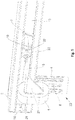
- the device is after FIG. 7 completed by the surrounding housing 2. It is clear that there is a change in the position of the protective tube 7 with the guide pieces 23, 24 from the rest position in the translational direction within the housing 2 by the longitudinal passage 13 in the housing 2 upon impact of a force on the stop 5. By applying the force on the stop 5, the tension spring element 19 is pulled apart and can thereby easily absorb the forces of the door leaf occurring in the final phase of the opening process.
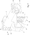
- FIG. 8 a modified type of Endlagendämpfungs Republic 1 is shown in a further preferred embodiment.
- the housing 2 is identical, with only the tension spring element 19 has not been posted on the fortifications 29. Rather, the housing terminations are performed in a form that brings an even easier and more efficient storage or assembly with it.
- the housing 2 is fastened via fasteners 43 to the substantially horizontal sections of the guide rails or the like.
- the Tension spring element 19 is equipped on both sides for structure-borne noise reduction with damping measures.
- the end-side design of the housing 2 with a closure piece 36 can the FIG. 10 be removed.
- the end piece 36 is formed so that it rests against edges of the housing 2 and at the same time has bends 39 which engage in the housing 2.
- a secure fit and secure placement of the end pieces 36 are achieved.
- a rubber element 35 whose outer surface is provided with a disc 34.
- a nut 33 is tightened, which is screwed onto a connecting element 32 which is provided with a thread 40.
- FIG. 11 Through the sectional view to FIG. 11 This embodiment can still be clarified, wherein the connecting element 32 with a lateral clearance and air with respect to a bore 25, the end piece 36 penetrates.
- the part of the connecting element 32 which dips within the housing 2, has a bore 41, in which preferably an eyelet 38 is hooked into a differently shaped end of the tension spring element 19.
- the design of this attachment of the tension spring element 19 is designed so that no contact with parts of the housing 2 can take place, characterized a body sound decoupling is achieved to a large extent.
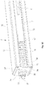
- the sectional view after FIG. 11 shows the tension spring element 19 in a loaded or partially loaded position, wherein the individual turns of the tension spring element 19 have been pulled apart.
- the representation of the FIG. 11 can be seen that a guide piece 42 has left in connection with the protective tube 7, the end position in the region of the end piece 36. By the guide pieces 24, 42, 23 a clean guidance of the protective tube 7 is achieved within the housing 2.
- FIG. 10 shows the tension spring element 19 in a partially loaded position, wherein in the longitudinal passage 13 of the housing 2, the connector 6 can come to outside of the housing 2.
- threaded holes 37 are still included, can be introduced via the screw 30.
- Such a connection shows the FIG. 9 , in which the attachment 43 is made with its angled portion 14 against the end piece 36.
- the connection between the bend 14 and the end piece 36 is achieved via the screw 30.
- 14 adjusting holes 31 have been inserted within the bend. So that the structure-borne noise decoupling can also retain its function with attached attachments 43, bores 25 are contained within the bends 14 and are so large that here too the rubber element 35 can pass with play.
- FIG. 12 shows again in an exploded view the components contained within the housing 2 and how they are functionally connected to the fasteners 43.
- the protective tube 7 is equipped on the left side with the guide piece 42, wherein on the circumference of the protective tube 7, the connecting piece 6 has been fixed non-positively and positively with the cantilevered stop 5.
- the tension spring element 19 is included within the skirt tube 7, the tension spring element 19 is included.
- the connecting element 32 On the eyelet 28, the connecting element 32 has been attached.
- the guide piece 23 with the bore 25 thus allows the connecting element 32 to pass with all-round great play and to penetrate the rubber element 35 and the disk 34 in order to be secured by the nut 33.
- the fixing takes place against the end piece 36.
- the end pieces 36 are inserted end into the housing 2 and are attached even with the fasteners 43 on a substantially horizontal extension of a guide rail or the like.
- the cushioning 1 can also be regarded as a safety device, for example, if the end position of the control of the door fails, or if the force applied to the door leaf manual forces in the open position are too large.
Landscapes
- Closing And Opening Devices For Wings, And Checks For Wings (AREA)
- Operating, Guiding And Securing Of Roll- Type Closing Members (AREA)
- Vibration Prevention Devices (AREA)
- Vibration Dampers (AREA)
Description
Die Erfindung betrifft ein Überkopftor mit einem Torblatt und seitlichen Führungsschienen, die einen im Wesentlichen vertikalen Abschnitt und einen im Wesentlichen horizontalen Abschnitt mit dazwischen verbindendem Bogenabschnitt aufweisen, wobei das Torblatt in den Führungsschienen ortsveränderbar angeordnet ist, wobei an den Enden der im Wesentlichen horizontalen Abschnitte der Führungsschienen eine Endlagendämpfungseinrichtung angeordnet ist.
Durch die
Ein Dämpfungsglied, das am freien Ende eines Gurtes in einer oder zwei Fangeinrichtungen befestigt ist, gibt die
In der
Ein Lamellentor, das in seitlichen Führungsschienen geführt wird, offenbart die
Endlagendämpfungseinrichtungen sind bei Toren hinlänglich bekannt. Sie sind dabei als Druckfedern ausgebildet, um so bei einem in die Endlage der Öffnungsposition hineinfahrendes Torblatt eine Dämpfung beim Aufprall ausführen zu können. Eine derartige Dämpfungseinrichtung schützt somit das Torblatt und die Führungsschienen vor Beschädigungen. Durch den Gebrauch von Druckfedern, die auf einem Rohr oder einer Stange geführt sind, entsteht durch diese Konstruktionsart eine unzumutbare Geräuschbelästigung.
Die Aufgabe der Erfindung besteht darin für ein Überkopftor mit einem Torblatt eine mechanisch arbeitende Endlagendämpfungseinrichtung, zu schaffen, die einfach herstellbar und für unterschiedliche Torgrößen und verschiedene Antriebsarten verwendbar ist.
Gelöst wird die Aufgabe der Erfindung durch die Merkmale des Anspruches 1. Die Unteransprüche geben dabei eine weitere Ausgestaltung des erfindungsgemäßen Gedankens wieder. Endlagendämpfungseinrichtungen sind bei Toren in einer Ausbildung als Überkopftor, die durch einen Antrieb automatisiert sind, grundsätzlich dazu da, dass die beim Öffnungsvorgang durch das Anfahren des Torblattes an einen Anschlag vorhandene kinetische Energie eliminiert wird. Würde dieses nicht durchgeführt, so könnte es während der Öffnungsphase des Torblattes, beispielsweise bei einem harten Anschlag, zu einer Beschädigung der Öffnungsmechanik kommen.
Bei manuell betriebenen Toren wird das Torblatt von Hand geöffnet und in seine Öffnungsstellung geschoben. Bei einem solchen Tor wird die Endlagendämpfungseinrichtung quasi als Anschlag verwendet und bildet eine Sicherung des Torblattes in seiner Offenstellung. Natürlich kann bei dieser Anwendung die Endlagendämpfungseinrichtung mit ihrer Dämpfungseinrichtung das Torblatt aus seiner Öffnungsstellung herausbringen, es findet jedoch keine Speicherung der Anfahrkräfte statt.
Die vorliegende Erfindung ist für beide Verwendungen einsatzfähig. Bei der nachfolgenden Beschreibung wird jedoch die automatisierte Ausbildung beschrieben.
Es wird eine Endlagendämpfungseinrichtung nach der Erfindung eingesetzt, die eine Vorrichtung enthält, die ein Dämpfungselement aufweist, dessen Bauform beim Auftreffen des sich öffnenden Torblattes nicht, wie im Stand der Technik verkleinert, sondern vergrößert wird. Erfindungsgemäß ist die Vorrichtung als Zugfeder ausgebildet, die beim Auftreffen des Torblattes die enthaltene kinetische Energie durch eine Vergrößerung ihrer Längenerstreckung eliminiert und auch gleichzeitig speichern kann. Durch die Verwendung von Zugfedern wird der Dämpfungsweg nicht so eingeschränkt wie bei Druckfedern, denn Druckfedern haben nur eine begrenzte Dämpfungsstrecke, weil der Federweg durch die gegeneinander stoßenden Windungen blockiert werden kann, in einem solchen Falle ist keine Dämpfungswirkung mehr gegeben.The invention relates to an overhead door with a door leaf and lateral guide rails, which have a substantially vertical portion and a substantially horizontal portion with arc portion connecting therebetween, wherein the door leaf is arranged in the guide rails so as to be displaceable, wherein at the ends of the substantially horizontal portions of Guide rails a Endlagendämpfungseinrichtung is arranged.
By the
An attenuator, which is attached to the free end of a belt in one or two catching devices, are the
In the
A Lamellentor, which is guided in lateral guide rails, discloses the
End position damping devices are well known in the case of gates. They are designed as compression springs, so as to be in a driving into the end position of the opening position door leaf To be able to perform damping on impact. Such a damping device thus protects the door leaf and the guide rails from damage. Through the use of compression springs, which are guided on a pipe or a rod, this type of construction creates an unreasonable noise nuisance.
The object of the invention is for an overhead door with a door leaf to create a mechanically operating Endlagendämpfungseinrichtung, which is easy to manufacture and usable for different Torgrößen and different types of drives.
The object of the invention is achieved by the features of claim 1. The dependent claims provide a further embodiment of the inventive concept again. End-position damping devices are in the case of gates in an embodiment as overhead door, which are automated by a drive, basically there to the fact that the opening process by the start of the door leaf against a stop existing kinetic energy is eliminated. If this were not carried out, it could come during the opening phase of the door leaf, for example, in a hard stop, to damage the opening mechanism.
In manually operated gates, the door leaf is opened by hand and pushed into its open position. In such a goal, the end position damping device is used as a kind of stop and forms a backup of the door leaf in its open position. Of course, in this application, the end position damping device with its damping device bring out the door leaf from its open position, but there is no storage of the starting forces.
The present invention is operational for both uses. In the following description, however, the automated training will be described.
It is a Endlagendämpfungseinrichtung used according to the invention, which includes a device having a damping element, the design of which does not decrease when hitting the opening door leaf, as in the prior art, but is increased. According to the invention, the device is designed as a tension spring, which eliminates the kinetic energy contained in the impact of the door leaf by increasing its length extension and can store at the same time. By using tension springs, the damping travel is not as limited as with compression springs, because compression springs have only a limited damping distance, because the spring travel through the against each other abutting turns can be blocked, in such a case no damping effect is given.
Das Zugfederelement nimmt beim Auftreffen des Torblattes auf die Vorrichtung zur Endlagendämpfung, die in dem bewegten Torblatt enthaltene kinetische Energie auf und speichert diese gleichzeitig.The tension spring element absorbs when striking the door leaf on the device for cushioning, the kinetic energy contained in the moving door leaf and stores them simultaneously.
Die Endlagendämpfungseinrichtung wird neben der vorbeschriebenen Verwendung auch dazu benutzt, um als Anfahrhilfe beim Schließvorgang des Torblattes aus der Öffnungsposition eine Unterstützung in Form einer Anfahrhilfe auszuüben. Die innerhalb der Endlagendämpfungseinrichtung beim Öffnungsvorgang aufgenommene kinetische Energie des Torblattes wird nach Beendigung des Öffnungsvorganges in der Endlagendämpfungseinrichtung als statische Energie gespeichert. Dieses ist möglich, weil der Antrieb des Torblattes eine Blockierung des Torblattes in der Öffnungsstellung bewirkt. Bei der Einleitung des Schließvorganges wird diese Blockierung aufgehoben und gleichzeitig gibt die mindestens eine Endlagendämpfungseinrichtung die zuvor gespeicherte Energie frei, indem eine Anschubhilfe auf das Torblatt erzeugt wird. Die Endlagendämpfungseinrichtung drückt dabei gegen das obere Ende des Torblattes und schiebt dieses, unter Zuhilfenahme des Antriebes, aus der Parkposition heraus. Danach nimmt die Endlagendämpfungseinrichtung wieder ihre Grundposition ein und kann bei dem nächsten Öffnungsvorgang wieder die kinetische Energie des anfahrenden Torblattes speichern. Da die Torgrößen unterschiedlich groß ausfallen, ist es bei der Endlagendämpfungseinrichtung möglich, die verwendeten Vorrichtungen der Energiespeicher einfach auszutauschen, um so eine einfache Anpassung an die unterschiedlichsten Torgrößen durchführen zu können. Dabei bleibt das Gehäuse der Dämpfungseinrichtung stets gleich erhalten.The end position damping device is also used in addition to the above-described use to exercise as traction help in the closing operation of the door leaf from the open position support in the form of traction. The kinetic energy of the door leaf received within the end position damping device during the opening process is stored as static energy after the end of the opening process in the end position damping device. This is possible because the drive of the door leaf causes a blockage of the door leaf in the open position. At the initiation of the closing process, this blockage is canceled and at the same time, the at least one end-position damping device releases the previously stored energy by generating a starting aid on the door leaf. The Endlagendämpfungseinrichtung presses against the upper end of the door leaf and pushes this, with the aid of the drive, out of the park position. Thereafter, the Endlagendämpfungseinrichtung resumes its basic position and can store the kinetic energy of the approaching door leaf again in the next opening process. Since the Torgrößen turn out to be different sizes, it is possible in the Endlagendämpfungseinrichtung easy to replace the devices used the energy storage, so as to be able to perform a simple adaptation to a variety of Torgrößen. The housing of the damping device always remains the same.
Bei der Endlagendämpfungseinrichtung kann je nach Größe des zu bewegenden Torblattes die Federkennlinie der Torgröße angepasst werden. Dabei ist es auch möglich, dass Zugfederelemente als Duplexfederelemente mit zwei ineinander angeordneten Zugfedern verwendet werden.In the end position damping device, depending on the size of the door leaf to be moved, the spring characteristic of the door size can be adjusted. It is also possible that tension spring elements are used as Duplexfederelemente with two nested tension springs.
In einer weiteren nicht erfindungsgemäßen Ausführungsform ist es auch möglich, mechanische Stoßabsorber einzusetzen. Des Weiteren kann die Endlagendämpfungseinrichtung nach einer nicht erfindungsgemäßen Ausführungsform auch ein elastisches Polymerelement beinhalten.In a further embodiment not according to the invention, it is also possible to use mechanical shock absorbers. Furthermore, the end-position damping device according to a non-inventive embodiment may also include an elastic polymer element.
Die vorbeschriebenen verschiedenen Vorrichtungen zur Endlagendämpfung sind innerhalb eines Gehäuses untergebracht. Diese Vorrichtungen können ohne Probleme eine translatorische Bewegung beim Auftreffen des Torblattendes ausführen und sich anschließend wieder beim Zurückgehen des Torblattes in ihre Grundstellung entspannen. Ein geeignetes Gehäuse kann rund, quadratisch oder rechteckig sein, je nach Verwendung der Endlagendämpfungseinrichtung. Während die im Stand der Technik bekannten Dämpfungseinrichtungen einen vor Kopf angeordneten Anschlag aufweisen, geht auch hier die Erfindung einen anderen Weg. Dafür weist das Gehäuse in seiner Längsrichtung einen offenen Durchtritt auf. Aus dem Durchtritt ragt ein Anschlag heraus, der mit der Vorrichtung verbunden ist. Ein derartiger Anschlag wird vorzugsweise aus einem Hartgummimaterial oder einem anderen geeigneten Material an der Auftrittsfläche des Torblattes ausgebildet.
Durch diese Gestaltung der Endlagendämpfungseinrichtung ist es möglich, diese seitlich an den im Wesentlichen horizontal verlaufenden Abschnitten der Führungsschienen durch Befestigungsbügel anzubringen. Dieses hat insbesondere den Vorteil, dass abhängig von unterschiedlichsten Torgrößen auch die Endlagendämpfungseinrichtung passgenau platziert werden kann. Ferner ist durch die gewählte Konstruktionsart ein leichtes Auswechseln bzw. ein Nachrüsten möglich. Dieses ist bei bekannten Federpuffern nicht möglich, da diese an Quertraversen zwischen den horizontalen Abschnitten der Führungsschienen angebracht sind.The above-described various end position damping devices are housed within a housing. These devices can easily perform a translational movement upon impact of the door leaf end and then relax again when returning the door leaf to its normal position. A suitable housing may be round, square or rectangular, depending on the use of the end position damping device. While the known in the prior art damping devices have a stop located in front of the head, here again, the invention takes a different route. For this, the housing has an open passage in its longitudinal direction. From the passage, a stop protrudes, which is connected to the device. Such a stop is preferably formed of a hard rubber material or other suitable material on the tread surface of the door leaf.
By means of this design of the end-position damping device, it is possible to attach these laterally to the essentially horizontally extending sections of the guide rails by means of mounting brackets. This has the particular advantage that depending on a wide variety of door sizes and the Endlagendämpfungseinrichtung can be accurately placed. Furthermore, a light replacement or retrofitting is possible by the chosen construction. This is not possible with known spring buffers, as they are mounted on crossbeams between the horizontal sections of the guide rails.
Erfindungsgemäß weist die Vorrichtung mit dem Dämpfungselement endseitig Befestigungen auf. In dem Gehäuse sind durch ein Schutzrohr miteinander verbundene Führungsstücke vorhanden. An dem Schutzrohr ist gleichzeitig seitlich der aus dem Gehäuse herausragende Anschlag angebracht. Dabei wird das Zugfederelement von dem Schutzrohr in der Parkposition im Wesentlichen umhüllt. Das Zugfederelement ist in einem der Führungsstücke, neben der stationären Befestigung, befestigt.According to the invention, the device with the damping element end fastenings. In the housing by a protective tube interconnected guide pieces are present. On the protective tube at the same time the side protruding from the housing stop is attached. In this case, the tension spring element is substantially enveloped by the protective tube in the parking position. The tension spring element is fastened in one of the guide pieces, next to the stationary attachment.
Um Geräuschentwicklungen zu unterbinden, kann das Gehäuse innen oder außen mit einem Dämpfungsmaterial zur Körperschallreduzierung ausgebildet sein. Ebenfalls kann das Schutzrohr auch mit derartigen Materialien, beispielsweise einem Kunststoffrohr, innen ausgekleidet werden.To prevent noise development, the housing may be formed inside or outside with a damping material for structure-borne noise reduction. Likewise, the protective tube can also be lined with such materials, for example a plastic tube, inside.
Bei der Dämpfungseinrichtung kann stets unter Verwendung des gleichen Gehäuses die Endausbildung unterschiedlich gestaltet werden. In einer ersten bevorzugten Ausführungsform bietet der Verschluss des Gehäuses endseitig die Möglichkeit, gleichzeitig über die Halterungen zur Befestigung an einer Führungsschiene auch die Befestigung eines Endes des Zugfederelementes auszuführen. Da beide Enden mit ihren Befestigungen gleich ausgebildet sind, ist es möglich, dass eine derartige Endlagendämpfungseinrichtung sowohl auf der rechten als auch auf der linken Seite bei Führungsschienenmontagen mit den gleichen Bauelementen verwendet werden kann.In the case of the damping device, the end configuration can always be designed differently using the same housing. In a first preferred embodiment, the closure of the housing offers at the end the possibility of simultaneously carrying out the fastening of one end of the tension spring element via the mountings for attachment to a guide rail. Since both ends are made the same with their attachments, it is possible that such end-position damping means can be used on both the right and left side in guide rail assemblies with the same components.
Um die Universalität der Endlagendämpfungseinrichtung noch weiter zu steigern, ist das Gehäuse mit eigenen Abschlussstücken ausgestattet. Das Zugfederelement wird über eines der Abschlussstücke befestigt. Hier ist es gleichzeitig möglich, dass auch zur Körperschalldämmung die Befestigung nicht direkt über die metallischen Abschlusstücken auszuführen, sondern unter Zwischenschaltung eines Gummielementes, um so eine Entkopplung der entstehenden Geräusche bei der Betätigung der Endlagendämpfungseinrichtung zu unterbinden. Bei dieser Ausführungsform kann das Gehäuse, einschließlich der Vorrichtung zur Endlagendämpfung, gut bevorratet werden und somit auch mit unterschiedlichsten Dämpfungsmitteln, sowie deren unterschiedlichen Stärken, ausgestattet werden. Auch diese Ausführungsform wird durch gleiche Befestigungsmittel an der Führungsschiene befestigt. Es versteht sich, dass diese Ausführung ebenfalls für linke und rechte Anwendungen einsetzbar ist.
Die zuvor beschriebenen, unterschiedlichen Ausführungen von Endlagendämpfungseinrichtungen mit einer Vorrichtung, die als Zugfederelement ausgebildet ist, kann eine Verwendung bei Überkopftoren, wie Sektionaltoren und Kipptoren, sowohl in manueller oder automatisierter Ausführung finden.
Weitere Vorteile, Merkmale und Anwendungsmöglichkeiten der vorliegenden Erfindung ergeben sich aus der nachfolgenden Beschreibung in Verbindung mit den in den Zeichnungen dargestellten Ausführungsbeispielen.
In der Beschreibung, in den Ansprüchen und in der Zeichnung werden die in der unten aufgeführten Liste der Bezugszeichen verwendeten Begriffe und zugeordneten Bezugszeichen verwendet. In der Zeichnung bedeutet:
- Fig. 1
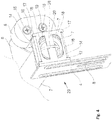
- Eine perspektivische Darstellung einer ersten bevorzugten Ausführung einer Endlagendämpfungseinrichtung;
- Fig. 2
- wie
Figur 1 , jedoch in einer rückseitigen Betrachtung; - Fig. 3
- ein Gehäuse für eine Endlagendämpfungseinrichtung;
- Fig. 4
- einen Teilausschnitt einer Befestigungsmöglichkeit eines Zugfederelementes;
- Fig. 5
- einen weiteren Teilausschnitt nach
Figur 4 ; - Fig. 6
- eine perspektivische Darstellung der innerhalb der Dämpfungseinrichtung vorhandenen Vorrichtung;
- Fig. 7
wie Figur 6 , jedoch in einer rückseitigen Betrachtungsperspektive;- Fig. 8
- eine perspektivische Darstellung einer zweiten bevorzugten Ausführung der Endlagendämpfungseinrichtung;
- Fig. 9
wie Figur 8 , jedoch in einer Teilansicht mit Befestigung des Zugfederelementes;- Fig. 10
wie Figur 9 ; jedoch unter Fortlassung der Befestigung;- Fig. 11
wie Figur 10 , jedoch in einer Schnittdarstellung und- Fig. 12
- die
Ausführungsform nach Figur 8 in einer Explosionsdarstellung.
In
Gemäß der Einzeldarstellung des Gehäuses 2, nach
In einer vergrößerten Ausschnittdarstellung nach
The previously described, different embodiments of end position damping devices with a device which is designed as a tension spring element can find use in overhead doors, such as sectional doors and tilting gates, both in manual or automated design.
Further advantages, features and possible applications of the present invention will become apparent from the following description in conjunction with the embodiments illustrated in the drawings.
In the description, the claims, and the drawing, the terms and associated reference numerals used in the list of reference numerals below are used. In the drawing:
- Fig. 1
- A perspective view of a first preferred embodiment of a cushioning device;
- Fig. 2
- as
FIG. 1 but in a back consideration; - Fig. 3
- a housing for a cushioning device;
- Fig. 4
- a partial section of a mounting possibility of a tension spring element;
- Fig. 5
- another partial section after
FIG. 4 ; - Fig. 6
- a perspective view of the existing within the damping device device;
- Fig. 7
- as
FIG. 6 but in a back viewing perspective; - Fig. 8
- a perspective view of a second preferred embodiment of the Endlagendämpfungseinrichtung;
- Fig. 9
- as
FIG. 8 but in a partial view with attachment of the tension spring element; - Fig. 10
- as
FIG. 9 ; but with the attachment omitted; - Fig. 11
- as
FIG. 10 but in a sectional view and - Fig. 12
- the embodiment according to
FIG. 8 in an exploded view.
In the
According to the individual representation of the
In an enlarged detail view after
The
Mit dem Schutzrohr 7 ist das Verbindungsstück 6 durch Kraft- und Formschluss verbunden. Das Verbindungsstück 6 weist eine Abwinkelung 21 auf, an der der Anschlag 5 befestigt ist. Von dem durch eine Verbindung 26 befestigten Verbindungsstück 6 an dem Schutzrohr 7 ist unter Verwendung einer Schräge 27 der Bereich zur Befestigung des Verbindungsstückes 6 über die Verbindung 26 an dem Schutzrohr 7 vergrößert worden.With the
In der
In der
In der
Die endseitige Ausbildung des Gehäuses 2 mit einem Abschlussstück 36 kann der
Durch die Schnittdarstellung nach
Auch die
Die
Wie die vorhergehende Beschreibung mit dem Zugfederelement 19 deutlich macht, ist entgegen den bekannten Ausführungen eines Anschlagpuffers eine Bewegungsumkehr, nämlich in Form der Zugfeder, ausgeführt worden. Diese kann in analoger Weise auch durch einen geeigneten, elastischen Polymerkörper oder aber auch mit einem Stoßabsorber ausgeführt werden. Durch die Kraftbeaufschlagung auf den Anschlag 5 werden somit in der Längserstreckung sowohl das Zugfederelement 19 oder aber auch das Polymerelement oder der Stoßabsorber in ihrer Erstreckung verlängert.As the preceding description makes clear with the
Die Endlagendämpfung 1 kann auch als Sicherheitseinrichtung angesehen werden, wenn beispielsweise die Endlagenabschaltung der Steuerung des Tores versagt, oder wenn die auf das Torblatt aufgebrachten manuellen Kräfte in der Öffnungsstellung zu groß sind.The cushioning 1 can also be regarded as a safety device, for example, if the end position of the control of the door fails, or if the force applied to the door leaf manual forces in the open position are too large.
- 11
- EndlagendämpfungseinrichtungEndlagendämpfungseinrichtung
- 22
- Gehäusecasing
- 33
- Abschlussgraduation
- 44
- Abschlussgraduation
- 55
- Anschlagattack
- 66
- Verbindungsstückjoint
- 77
- Schutzrohrthermowell
- 88th
- Durchbruchbreakthrough
- 99
- BasisBase
- 1010
- SeitenwandSide wall
- 1111
- SeitenwandSide wall
- 1212
- Stegweb
- 1313
- Durchtrittpassage
- 1414
- Abwinkelungangulation
- 1515
- Befestigungsschraubenmounting screws
- 1616
- Vorsprunghead Start
- 1717
- Anschlagattack
- 1818
- Durchbruchbreakthrough
- 1919
- Zugfederelementtension spring
- 2020
- Stegweb
- 2121
- Abwinkelungangulation
- 2222
- Federhalterungspring retainer
- 2323
- Führungsstückguide piece
- 2424
- Führungsstückguide piece
- 2525
- Bohrungdrilling
- 2626
- Verbindungconnection
- 2727
- Schrägeslope
- 2828
- Öseeyelet
- 2929
- Befestigungattachment
- 3030
- Verschraubungscrew
- 3131
- Verstellbohrungadjusting hole
- 3232
- Verbindungselementconnecting member
- 3333
- Muttermother
- 3434
- Scheibedisc
- 3535
- Gummielementrubber element
- 3636
- Abschlussstückterminating piece
- 3737
- Gewindebohrungthreaded hole
- 3838
- Öseeyelet
- 3939
- Abwinkelungangulation
- 4040
- Gewindethread
- 4141
- Bohrungdrilling
- 4242
- Führungsstückguide piece
- 4343
- Befestigungattachment
Claims (12)
- An overhead door with a door leaf and lateral guiding rails, which include an essentially vertical section and an essentially horizontal section with an intermediate connecting arch section, wherein the door leaf is disposed to be mobile in the guiding rails, wherein at the ends of the essentially horizontal sections of the guiding rails at least one terminal position dampening equipment (1) is disposed, characterized in that the terminal position dampening equipment (1) includes a housing (2) with a device, which is configured as a draw spring element (19), the structural shape thereof in the longitudinal extension thereof being increased upon contact with the door leaf, wherein the housing (2) as a hollow profile has a square or round or rectangular cross-section with a long-sided open passage (13) for a changeable abutment (5), which is connected to the device in longitudinal direction of the housing (2), and in that the housing (2) at end sides includes terminal parts (3, 4), which include the attachments (29, 43) for the abutment against at least one of the guiding rails, wherein the draw spring element (19) is attached at one end to parts of the attachment (29, 43) and, at the other end, to a guiding part (23), which is displaceable in the housing (2), and in that the guiding part (23) is connected to another guiding part (24) with the distance of a protecting tube (7), wherein the protecting tube (7) in the resting position essentially envelopes the draw spring element (19), and in that the abutment (5) is attached to the protecting tube (7).
- The overhead door of claim 1, characterized in that the housing (2) is closed off by terminal parts (36) at end sides, wherein simultaneously the attachment of the draw spring element (19) is executable via the terminal part (36).
- The overhead door according to claim 2, characterized in that the terminal part (36) includes a bore (25), through which a connecting element (32) with a thread (40) passes contact-less with play all around, which is connected at one end to the draw spring element (19), and, at the other end, bears against the terminal part (36) and is fixed by means of a nut (33).
- The overhead door according to claim 3, characterized in that between the nut (33) and the terminal part (36), a decoupling of structure borne sound is disposed, preferably in the shape of a rubber element (35).
- The overhead door according to any of the claims 2, 3 and 4, characterized in that the housing (2) with the terminal parts (36) is provided with an attachment (43), to which at least one of the guiding rails may be attached.
- The overhead door according to any of the preceding claims, characterized in that the housing (2) or parts of the housing (2) are provided with a coating or equipment reducing structure borne sound.
- The overhead door according to any of the preceding claims, characterized in that terminal position dampening equipment (1) is directly or indirectly exchangeably connectable to at least one of the essentially horizontally extending sections of the guiding rails.
- The overhead door according to any of the preceding claims, characterized in that the device of the terminal position dampening equipment (1) is exchangeable and adaptable to the kinetic energy to be absorbed by the moved door leaf.
- The overhead door according to any of the preceding claims, characterized in that the draw spring element (19) is configured as a duplex spring.
- The overhead door according to any of the preceding claims, characterized in that the door leaf is a component of a sectional door or an up-and-over-door.
- The overhead door according to any of the preceding claims, characterized in that in a door leaf automated by means of a drive device, the kinetic energy of the opening procedure contained in the door leaf may be absorbed by and stored in the device, and in that, during a closing procedure of the door leaf, the stored energy of the device may be released against the door leaf.
- The overhead door according to any of the preceding claims, characterized in that in a manually operated door leaf the terminal position dampening equipment (1) is employable as an abutment buffer in the terminal position of the opening position.
Priority Applications (1)
| Application Number | Priority Date | Filing Date | Title |
|---|---|---|---|
| PL16151469T PL3045643T3 (en) | 2015-01-16 | 2016-01-15 | Gate leaf |
Applications Claiming Priority (1)
| Application Number | Priority Date | Filing Date | Title |
|---|---|---|---|
| DE102015100617.0A DE102015100617B4 (en) | 2015-01-16 | 2015-01-16 | Door leaf |
Publications (2)
| Publication Number | Publication Date |
|---|---|
| EP3045643A1 EP3045643A1 (en) | 2016-07-20 |
| EP3045643B1 true EP3045643B1 (en) | 2019-01-02 |
Family
ID=55173796
Family Applications (1)
| Application Number | Title | Priority Date | Filing Date |
|---|---|---|---|
| EP16151469.0A Active EP3045643B1 (en) | 2015-01-16 | 2016-01-15 | Gate leaf |
Country Status (5)
| Country | Link |
|---|---|
| EP (1) | EP3045643B1 (en) |
| DE (1) | DE102015100617B4 (en) |
| DK (1) | DK3045643T3 (en) |
| ES (1) | ES2718741T3 (en) |
| PL (1) | PL3045643T3 (en) |
Families Citing this family (3)
| Publication number | Priority date | Publication date | Assignee | Title |
|---|---|---|---|---|
| DE102018108217A1 (en) | 2018-04-06 | 2019-10-10 | Alpha Deuren International Bv | Endlagenspeicher device and a gate with a Endlagenenspeichervorrichtung |
| DE102018129581B4 (en) | 2018-11-23 | 2023-08-03 | Alpha Deuren International Bv | Auxiliary drive for a motor-driven door leaf, as well as a door with an auxiliary drive |
| DE102019131119B4 (en) * | 2019-11-18 | 2025-07-03 | Alpha Deuren International Bv | Auxiliary drive with damping device for a movable door leaf |
Family Cites Families (7)
| Publication number | Priority date | Publication date | Assignee | Title |
|---|---|---|---|---|
| DE7540330U (en) | 1975-12-18 | 1976-08-19 | Ing. Lang & Menke Gmbh, 5870 Hemer | BRAKE DEVICE FOR SWINGING GATES |
| DE3206813C1 (en) | 1982-02-25 | 1983-11-17 | Döring, Erich, 9442 Berneck, St. Gallen | Garage door with a door-catching device |
| LU90195B1 (en) | 1998-01-15 | 1999-07-16 | Wurth Paul Sa | Tapping gutter for an iron smelter |
| DE50006569D1 (en) * | 1999-08-12 | 2004-07-01 | Johann Henkenjohann | sectional door |
| LU90915B1 (en) * | 2002-04-29 | 2003-10-30 | Pettinger S A R L | Sectional gate |
| DE102004029990B4 (en) * | 2004-06-21 | 2008-01-17 | Bosch Rexroth Pneumatics Gmbh | Piston-cylinder unit |
| DE202005006255U1 (en) | 2005-04-19 | 2006-08-31 | Hörmann KG Antriebstechnik | Power-operated door used as a garage door comprises a drive arrangement having a motor and a traction gearing having a traction device which is tensioned relative to the door leaf in the opening direction |
-
2015
- 2015-01-16 DE DE102015100617.0A patent/DE102015100617B4/en active Active
-
2016
- 2016-01-15 ES ES16151469T patent/ES2718741T3/en active Active
- 2016-01-15 EP EP16151469.0A patent/EP3045643B1/en active Active
- 2016-01-15 PL PL16151469T patent/PL3045643T3/en unknown
- 2016-01-15 DK DK16151469.0T patent/DK3045643T3/en active
Non-Patent Citations (1)
| Title |
|---|
| None * |
Also Published As
| Publication number | Publication date |
|---|---|
| DK3045643T3 (en) | 2019-04-15 |
| PL3045643T3 (en) | 2019-08-30 |
| EP3045643A1 (en) | 2016-07-20 |
| DE102015100617B4 (en) | 2021-03-04 |
| DE102015100617A1 (en) | 2016-07-21 |
| ES2718741T3 (en) | 2019-07-04 |
Similar Documents
| Publication | Publication Date | Title |
|---|---|---|
| EP2050907B1 (en) | Dampening and drawing device | |
| EP1247930B1 (en) | Catch device for trolleys guided in rails | |
| EP2333218B1 (en) | Device for damping the relative motion of moving parts, in particular sliding doors | |
| EP2617336B1 (en) | Shower separator | |
| DE102009042486A1 (en) | sliding door | |
| DE2917797A1 (en) | CLAMPING SAFETY FOR SELF-OPENING AND CLOSING DOORS | |
| EP3199078B1 (en) | Shower enclosure with a sliding door which can be actively moved using a spring/damper unit into end positions | |
| DE202008014529U1 (en) | Guide device for sliding doors | |
| EP3235983A1 (en) | Sliding door assembly and rail device | |
| EP3045643B1 (en) | Gate leaf | |
| DE102011011113A1 (en) | Frame system of insect guard mounted in window and door of building, for preventing invasion of e.g. insect, has sliding element which is connected to guide plates along longitudinal rails of clamping element | |
| DE202007015807U1 (en) | Sliding door with limiting device | |
| EP1613828B1 (en) | Device for closing a door | |
| EP3763911B1 (en) | Guide rail device for a rolling gate or rolling grille | |
| DE102020102023A1 (en) | Sliding door fitting and method for moving a control device | |
| DE202018101882U1 (en) | Endlagendämpfungsvorrichtung | |
| EP3656958B1 (en) | Auxiliary drive comprising a damping device for a motor-driven gate leaf, and a gate, the rotor blade of which is equipped with an auxiliary drive that contains a damping device | |
| EP2366858A2 (en) | Device for closing an opening | |
| DE102011000295A1 (en) | Resetting apparatus for automatic closing or opening of sliding door of sliding door system, comprises elongated elastic element with two ends, where former end is connected with fastening medium for fastening at sliding door | |
| DE202007013802U1 (en) | Single sheet overhead door and pretensioner therefor | |
| EP0495498B1 (en) | Device for incorporating the end stop of a guide rail for rollers of a doorpanel | |
| DE19501097C2 (en) | Up-and-over gate | |
| EP3680445A1 (en) | Safety guide profile and movable door leaf comprising a safety profile | |
| DE102008047757B4 (en) | Device for closing an opening | |
| DE102011107961B4 (en) | Support system for a sliding door |
Legal Events
| Date | Code | Title | Description |
|---|---|---|---|
| PUAI | Public reference made under article 153(3) epc to a published international application that has entered the european phase |
Free format text: ORIGINAL CODE: 0009012 |
|
| AK | Designated contracting states |
Kind code of ref document: A1 Designated state(s): AL AT BE BG CH CY CZ DE DK EE ES FI FR GB GR HR HU IE IS IT LI LT LU LV MC MK MT NL NO PL PT RO RS SE SI SK SM TR |
|
| AX | Request for extension of the european patent |
Extension state: BA ME |
|
| STAA | Information on the status of an ep patent application or granted ep patent |
Free format text: STATUS: REQUEST FOR EXAMINATION WAS MADE |
|
| 17P | Request for examination filed |
Effective date: 20170120 |
|
| RBV | Designated contracting states (corrected) |
Designated state(s): AL AT BE BG CH CY CZ DE DK EE ES FI FR GB GR HR HU IE IS IT LI LT LU LV MC MK MT NL NO PL PT RO RS SE SI SK SM TR |
|
| STAA | Information on the status of an ep patent application or granted ep patent |
Free format text: STATUS: EXAMINATION IS IN PROGRESS |
|
| 17Q | First examination report despatched |
Effective date: 20180201 |
|
| GRAP | Despatch of communication of intention to grant a patent |
Free format text: ORIGINAL CODE: EPIDOSNIGR1 |
|
| STAA | Information on the status of an ep patent application or granted ep patent |
Free format text: STATUS: GRANT OF PATENT IS INTENDED |
|
| INTG | Intention to grant announced |
Effective date: 20180815 |
|
| GRAS | Grant fee paid |
Free format text: ORIGINAL CODE: EPIDOSNIGR3 |
|
| GRAA | (expected) grant |
Free format text: ORIGINAL CODE: 0009210 |
|
| STAA | Information on the status of an ep patent application or granted ep patent |
Free format text: STATUS: THE PATENT HAS BEEN GRANTED |
|
| AK | Designated contracting states |
Kind code of ref document: B1 Designated state(s): AL AT BE BG CH CY CZ DE DK EE ES FI FR GB GR HR HU IE IS IT LI LT LU LV MC MK MT NL NO PL PT RO RS SE SI SK SM TR |
|
| REG | Reference to a national code |
Ref country code: GB Ref legal event code: FG4D Free format text: NOT ENGLISH |
|
| REG | Reference to a national code |
Ref country code: CH Ref legal event code: EP Ref country code: AT Ref legal event code: REF Ref document number: 1084589 Country of ref document: AT Kind code of ref document: T Effective date: 20190115 |
|
| REG | Reference to a national code |
Ref country code: IE Ref legal event code: FG4D Free format text: LANGUAGE OF EP DOCUMENT: GERMAN |
|
| REG | Reference to a national code |
Ref country code: DE Ref legal event code: R096 Ref document number: 502016003021 Country of ref document: DE |
|
| REG | Reference to a national code |
Ref country code: NL Ref legal event code: FP |
|
| REG | Reference to a national code |
Ref country code: SE Ref legal event code: TRGR |
|
| REG | Reference to a national code |
Ref country code: DK Ref legal event code: T3 Effective date: 20190408 |
|
| REG | Reference to a national code |
Ref country code: LT Ref legal event code: MG4D |
|
| REG | Reference to a national code |
Ref country code: ES Ref legal event code: FG2A Ref document number: 2718741 Country of ref document: ES Kind code of ref document: T3 Effective date: 20190704 |
|
| PG25 | Lapsed in a contracting state [announced via postgrant information from national office to epo] |
Ref country code: PT Free format text: LAPSE BECAUSE OF FAILURE TO SUBMIT A TRANSLATION OF THE DESCRIPTION OR TO PAY THE FEE WITHIN THE PRESCRIBED TIME-LIMIT Effective date: 20190502 Ref country code: LT Free format text: LAPSE BECAUSE OF FAILURE TO SUBMIT A TRANSLATION OF THE DESCRIPTION OR TO PAY THE FEE WITHIN THE PRESCRIBED TIME-LIMIT Effective date: 20190102 Ref country code: NO Free format text: LAPSE BECAUSE OF FAILURE TO SUBMIT A TRANSLATION OF THE DESCRIPTION OR TO PAY THE FEE WITHIN THE PRESCRIBED TIME-LIMIT Effective date: 20190402 Ref country code: FI Free format text: LAPSE BECAUSE OF FAILURE TO SUBMIT A TRANSLATION OF THE DESCRIPTION OR TO PAY THE FEE WITHIN THE PRESCRIBED TIME-LIMIT Effective date: 20190102 |
|
| PG25 | Lapsed in a contracting state [announced via postgrant information from national office to epo] |
Ref country code: IS Free format text: LAPSE BECAUSE OF FAILURE TO SUBMIT A TRANSLATION OF THE DESCRIPTION OR TO PAY THE FEE WITHIN THE PRESCRIBED TIME-LIMIT Effective date: 20190502 Ref country code: BG Free format text: LAPSE BECAUSE OF FAILURE TO SUBMIT A TRANSLATION OF THE DESCRIPTION OR TO PAY THE FEE WITHIN THE PRESCRIBED TIME-LIMIT Effective date: 20190402 Ref country code: RS Free format text: LAPSE BECAUSE OF FAILURE TO SUBMIT A TRANSLATION OF THE DESCRIPTION OR TO PAY THE FEE WITHIN THE PRESCRIBED TIME-LIMIT Effective date: 20190102 Ref country code: HR Free format text: LAPSE BECAUSE OF FAILURE TO SUBMIT A TRANSLATION OF THE DESCRIPTION OR TO PAY THE FEE WITHIN THE PRESCRIBED TIME-LIMIT Effective date: 20190102 Ref country code: LV Free format text: LAPSE BECAUSE OF FAILURE TO SUBMIT A TRANSLATION OF THE DESCRIPTION OR TO PAY THE FEE WITHIN THE PRESCRIBED TIME-LIMIT Effective date: 20190102 |
|
| REG | Reference to a national code |
Ref country code: CH Ref legal event code: PL |
|
| PG25 | Lapsed in a contracting state [announced via postgrant information from national office to epo] |
Ref country code: LU Free format text: LAPSE BECAUSE OF NON-PAYMENT OF DUE FEES Effective date: 20190115 |
|
| REG | Reference to a national code |
Ref country code: DE Ref legal event code: R097 Ref document number: 502016003021 Country of ref document: DE |
|
| REG | Reference to a national code |
Ref country code: IE Ref legal event code: MM4A |
|
| PG25 | Lapsed in a contracting state [announced via postgrant information from national office to epo] |
Ref country code: CZ Free format text: LAPSE BECAUSE OF FAILURE TO SUBMIT A TRANSLATION OF THE DESCRIPTION OR TO PAY THE FEE WITHIN THE PRESCRIBED TIME-LIMIT Effective date: 20190102 Ref country code: SK Free format text: LAPSE BECAUSE OF FAILURE TO SUBMIT A TRANSLATION OF THE DESCRIPTION OR TO PAY THE FEE WITHIN THE PRESCRIBED TIME-LIMIT Effective date: 20190102 Ref country code: MC Free format text: LAPSE BECAUSE OF FAILURE TO SUBMIT A TRANSLATION OF THE DESCRIPTION OR TO PAY THE FEE WITHIN THE PRESCRIBED TIME-LIMIT Effective date: 20190102 Ref country code: AL Free format text: LAPSE BECAUSE OF FAILURE TO SUBMIT A TRANSLATION OF THE DESCRIPTION OR TO PAY THE FEE WITHIN THE PRESCRIBED TIME-LIMIT Effective date: 20190102 Ref country code: EE Free format text: LAPSE BECAUSE OF FAILURE TO SUBMIT A TRANSLATION OF THE DESCRIPTION OR TO PAY THE FEE WITHIN THE PRESCRIBED TIME-LIMIT Effective date: 20190102 Ref country code: RO Free format text: LAPSE BECAUSE OF FAILURE TO SUBMIT A TRANSLATION OF THE DESCRIPTION OR TO PAY THE FEE WITHIN THE PRESCRIBED TIME-LIMIT Effective date: 20190102 Ref country code: IT Free format text: LAPSE BECAUSE OF FAILURE TO SUBMIT A TRANSLATION OF THE DESCRIPTION OR TO PAY THE FEE WITHIN THE PRESCRIBED TIME-LIMIT Effective date: 20190102 |
|
| PLBE | No opposition filed within time limit |
Free format text: ORIGINAL CODE: 0009261 |
|
| STAA | Information on the status of an ep patent application or granted ep patent |
Free format text: STATUS: NO OPPOSITION FILED WITHIN TIME LIMIT |
|
| PG25 | Lapsed in a contracting state [announced via postgrant information from national office to epo] |
Ref country code: SM Free format text: LAPSE BECAUSE OF FAILURE TO SUBMIT A TRANSLATION OF THE DESCRIPTION OR TO PAY THE FEE WITHIN THE PRESCRIBED TIME-LIMIT Effective date: 20190102 |
|
| 26N | No opposition filed |
Effective date: 20191003 |
|
| PG25 | Lapsed in a contracting state [announced via postgrant information from national office to epo] |
Ref country code: LI Free format text: LAPSE BECAUSE OF NON-PAYMENT OF DUE FEES Effective date: 20190131 Ref country code: CH Free format text: LAPSE BECAUSE OF NON-PAYMENT OF DUE FEES Effective date: 20190131 |
|
| PG25 | Lapsed in a contracting state [announced via postgrant information from national office to epo] |
Ref country code: IE Free format text: LAPSE BECAUSE OF NON-PAYMENT OF DUE FEES Effective date: 20190115 |
|
| PG25 | Lapsed in a contracting state [announced via postgrant information from national office to epo] |
Ref country code: SI Free format text: LAPSE BECAUSE OF FAILURE TO SUBMIT A TRANSLATION OF THE DESCRIPTION OR TO PAY THE FEE WITHIN THE PRESCRIBED TIME-LIMIT Effective date: 20190102 |
|
| PG25 | Lapsed in a contracting state [announced via postgrant information from national office to epo] |
Ref country code: TR Free format text: LAPSE BECAUSE OF FAILURE TO SUBMIT A TRANSLATION OF THE DESCRIPTION OR TO PAY THE FEE WITHIN THE PRESCRIBED TIME-LIMIT Effective date: 20190102 |
|
| PG25 | Lapsed in a contracting state [announced via postgrant information from national office to epo] |
Ref country code: MT Free format text: LAPSE BECAUSE OF FAILURE TO SUBMIT A TRANSLATION OF THE DESCRIPTION OR TO PAY THE FEE WITHIN THE PRESCRIBED TIME-LIMIT Effective date: 20190102 |
|
| PG25 | Lapsed in a contracting state [announced via postgrant information from national office to epo] |
Ref country code: CY Free format text: LAPSE BECAUSE OF FAILURE TO SUBMIT A TRANSLATION OF THE DESCRIPTION OR TO PAY THE FEE WITHIN THE PRESCRIBED TIME-LIMIT Effective date: 20190102 |
|
| PG25 | Lapsed in a contracting state [announced via postgrant information from national office to epo] |
Ref country code: GR Free format text: LAPSE BECAUSE OF FAILURE TO SUBMIT A TRANSLATION OF THE DESCRIPTION OR TO PAY THE FEE WITHIN THE PRESCRIBED TIME-LIMIT Effective date: 20190102 |
|
| PG25 | Lapsed in a contracting state [announced via postgrant information from national office to epo] |
Ref country code: HU Free format text: LAPSE BECAUSE OF FAILURE TO SUBMIT A TRANSLATION OF THE DESCRIPTION OR TO PAY THE FEE WITHIN THE PRESCRIBED TIME-LIMIT; INVALID AB INITIO Effective date: 20160115 |
|
| REG | Reference to a national code |
Ref country code: AT Ref legal event code: MM01 Ref document number: 1084589 Country of ref document: AT Kind code of ref document: T Effective date: 20210115 |
|
| PG25 | Lapsed in a contracting state [announced via postgrant information from national office to epo] |
Ref country code: AT Free format text: LAPSE BECAUSE OF NON-PAYMENT OF DUE FEES Effective date: 20210115 |
|
| PG25 | Lapsed in a contracting state [announced via postgrant information from national office to epo] |
Ref country code: MK Free format text: LAPSE BECAUSE OF FAILURE TO SUBMIT A TRANSLATION OF THE DESCRIPTION OR TO PAY THE FEE WITHIN THE PRESCRIBED TIME-LIMIT Effective date: 20190102 |
|
| PGFP | Annual fee paid to national office [announced via postgrant information from national office to epo] |
Ref country code: NL Payment date: 20250121 Year of fee payment: 10 |
|
| PGFP | Annual fee paid to national office [announced via postgrant information from national office to epo] |
Ref country code: DE Payment date: 20250121 Year of fee payment: 10 |
|
| PGFP | Annual fee paid to national office [announced via postgrant information from national office to epo] |
Ref country code: DK Payment date: 20250124 Year of fee payment: 10 |
|
| PGFP | Annual fee paid to national office [announced via postgrant information from national office to epo] |
Ref country code: ES Payment date: 20250226 Year of fee payment: 10 |
|
| PGFP | Annual fee paid to national office [announced via postgrant information from national office to epo] |
Ref country code: SE Payment date: 20250121 Year of fee payment: 10 |
|
| PGFP | Annual fee paid to national office [announced via postgrant information from national office to epo] |
Ref country code: BE Payment date: 20250121 Year of fee payment: 10 |
|
| PGFP | Annual fee paid to national office [announced via postgrant information from national office to epo] |
Ref country code: FR Payment date: 20250127 Year of fee payment: 10 Ref country code: PL Payment date: 20250103 Year of fee payment: 10 |
|
| PGFP | Annual fee paid to national office [announced via postgrant information from national office to epo] |
Ref country code: GB Payment date: 20250128 Year of fee payment: 10 |