EP3025893A1 - Vorrichtung zum Schutz vor Fehlbetankung - Google Patents
Vorrichtung zum Schutz vor Fehlbetankung Download PDFInfo
- Publication number
- EP3025893A1 EP3025893A1 EP14195241.6A EP14195241A EP3025893A1 EP 3025893 A1 EP3025893 A1 EP 3025893A1 EP 14195241 A EP14195241 A EP 14195241A EP 3025893 A1 EP3025893 A1 EP 3025893A1
- Authority
- EP
- European Patent Office
- Prior art keywords
- housing
- tab
- closure
- closure element
- misfuelling
- Prior art date
- Legal status (The legal status is an assumption and is not a legal conclusion. Google has not performed a legal analysis and makes no representation as to the accuracy of the status listed.)
- Granted
Links
- 239000000446 fuel Substances 0.000 claims description 21
- 238000003780 insertion Methods 0.000 claims description 7
- 230000037431 insertion Effects 0.000 claims description 7
- 238000000926 separation method Methods 0.000 claims description 3
- 239000000945 filler Substances 0.000 description 9
- 239000002131 composite material Substances 0.000 description 6
- 239000003502 gasoline Substances 0.000 description 4
- 239000002283 diesel fuel Substances 0.000 description 3
- 239000007769 metal material Substances 0.000 description 3
- 239000000463 material Substances 0.000 description 2
- 229910000639 Spring steel Inorganic materials 0.000 description 1
- 230000015572 biosynthetic process Effects 0.000 description 1
- 239000004020 conductor Substances 0.000 description 1
- 230000001419 dependent effect Effects 0.000 description 1
- 238000011161 development Methods 0.000 description 1
- 230000018109 developmental process Effects 0.000 description 1
- 239000000295 fuel oil Substances 0.000 description 1
- 238000005192 partition Methods 0.000 description 1
Images


Classifications
-
- B—PERFORMING OPERATIONS; TRANSPORTING
- B60—VEHICLES IN GENERAL
- B60K—ARRANGEMENT OR MOUNTING OF PROPULSION UNITS OR OF TRANSMISSIONS IN VEHICLES; ARRANGEMENT OR MOUNTING OF PLURAL DIVERSE PRIME-MOVERS IN VEHICLES; AUXILIARY DRIVES FOR VEHICLES; INSTRUMENTATION OR DASHBOARDS FOR VEHICLES; ARRANGEMENTS IN CONNECTION WITH COOLING, AIR INTAKE, GAS EXHAUST OR FUEL SUPPLY OF PROPULSION UNITS IN VEHICLES
- B60K15/00—Arrangement in connection with fuel supply of combustion engines or other fuel consuming energy converters, e.g. fuel cells; Mounting or construction of fuel tanks
- B60K15/03—Fuel tanks
- B60K15/04—Tank inlets
- B60K2015/0458—Details of the tank inlet
- B60K2015/0461—Details of the tank inlet comprising a filler pipe shutter, e.g. trap, door or flap for fuel inlet
-
- B—PERFORMING OPERATIONS; TRANSPORTING
- B60—VEHICLES IN GENERAL
- B60K—ARRANGEMENT OR MOUNTING OF PROPULSION UNITS OR OF TRANSMISSIONS IN VEHICLES; ARRANGEMENT OR MOUNTING OF PLURAL DIVERSE PRIME-MOVERS IN VEHICLES; AUXILIARY DRIVES FOR VEHICLES; INSTRUMENTATION OR DASHBOARDS FOR VEHICLES; ARRANGEMENTS IN CONNECTION WITH COOLING, AIR INTAKE, GAS EXHAUST OR FUEL SUPPLY OF PROPULSION UNITS IN VEHICLES
- B60K15/00—Arrangement in connection with fuel supply of combustion engines or other fuel consuming energy converters, e.g. fuel cells; Mounting or construction of fuel tanks
- B60K15/03—Fuel tanks
- B60K15/04—Tank inlets
- B60K2015/0458—Details of the tank inlet
- B60K2015/0477—Details of the filler neck tank side
-
- B—PERFORMING OPERATIONS; TRANSPORTING
- B60—VEHICLES IN GENERAL
- B60K—ARRANGEMENT OR MOUNTING OF PROPULSION UNITS OR OF TRANSMISSIONS IN VEHICLES; ARRANGEMENT OR MOUNTING OF PLURAL DIVERSE PRIME-MOVERS IN VEHICLES; AUXILIARY DRIVES FOR VEHICLES; INSTRUMENTATION OR DASHBOARDS FOR VEHICLES; ARRANGEMENTS IN CONNECTION WITH COOLING, AIR INTAKE, GAS EXHAUST OR FUEL SUPPLY OF PROPULSION UNITS IN VEHICLES
- B60K15/00—Arrangement in connection with fuel supply of combustion engines or other fuel consuming energy converters, e.g. fuel cells; Mounting or construction of fuel tanks
- B60K15/03—Fuel tanks
- B60K15/04—Tank inlets
- B60K2015/0458—Details of the tank inlet
- B60K2015/0483—Means to inhibit the introduction of too small or too big filler nozzles
Definitions
- the present invention relates to a device for protection against misfuelling, in particular of a diesel fuel-powered motor vehicle.
- motor vehicles require different fuels, whereby refueling the motor vehicle with an unsuitable fuel can lead to enormous damage to the motor vehicle.
- a first step to prevent misfuelling was the introduction of nozzles with different diameters - for example, currently have diesel nozzles with a diameter of ⁇ 23.6 mm, gasoline dispensing valves, however, a diameter of up to 21.3 mm.
- Nozzle valves are colloquially called also nozzle nozzles and are connected via a hose to the fuel pump.
- the DE 103 20 992 A1 describes, for example, such a device, wherein an accessory device is mounted in the tank neck of a vehicle.
- the annular additional device causes a reduction of the diameter of the filler neck by means of a plurality of radial elements arranged on the circumference. The diameter is smaller in the region of the radial elements than the diameter of the suitable fuel nozzle.
- the additional device is designed conically upwards to the opening, so that the appropriate fuel nozzle can be easily and simply angeschnäbelt.
- the radial elements Upon further insertion of the appropriate fuel nozzle, the radial elements are deformed, tilted or moved so that the opening widens and the fuel nozzle can be fully inserted into the tank tube.
- the elastic or articulated movement of the radial elements causes a tilting or rotational movement of barbs on the device. An unsuitable fuel nozzle sticks to the barb and can not be inserted further into the tank tube.
- the document DE 101 57 090 C1 also describes an arrangement for preventing refueling of a diesel vehicle with unleaded gasoline.
- a locking lever In the filler neck while a locking lever is provided which is movable between a rest position and a Betank ein back and forth.
- the locking lever is provided at its end facing away from the tank opening with a locking tab which protrudes in the rest position in the cross section of the filler neck and an insertion of an unsuitable Nozzle in the tank prevented.
- the locking lever has at its end facing the tank opening to an actuating extension, which is actuated by a suitable nozzle and by means of the locking lever is moved to a refueling position.
- a device for protection against misfuelling comprising a housing and a closure element arranged in the housing, wherein the closure element has circumferentially at least one locking tab and the housing has at least one housing tab associated with the locking tab, wherein the locking tab with the associated housing tab a Locking connection forms, wherein the locking tab and the associated housing tab are formed so that the locking connection is reversibly solved by inserting a suitable nozzle, so that the closure element is then axially movable relative to the housing, whereby a separating element can be opened and a refueling is made possible.
- the suitable fuel nozzle is, in particular, a fuel nozzle in a form which is customary for diesel fuels.
- An unsuitable fuel nozzle is a smaller diameter nozzle compared to a diesel fuel nozzle, as is the case for gasoline fuel nozzles, for example.
- the device according to the invention comprises the housing, wherein the housing has a tank-side housing end, a filling-side housing end, and a housing interior.
- the housing is preferably made of plastic.
- a housing made of a metallic material is also applicable.
- the closure element is according to the invention in the housing, i. in the housing interior, arranged, which among other things, a compact design of the device according to the invention is achieved.
- the closure element is preferably made of plastic.
- a made of a metallic material closure element is also applicable.
- the closure element has at least one closure flap on its circumference, wherein the closure flap is arranged on the circumference of the closure element.
- the closure flap is preferably made of the same material as the closure element.
- the housing according to the present invention has at least one housing lug on its circumference, wherein a housing lug is assigned to a closure lug.
- the housing tab is preferably made of the same material as the housing.
- the closure tab with the associated housing tab forms the latching connection.
- the locking tab and the associated housing tab are designed so that the locking connection between the locking tab and the associated housing tab is achieved by inserting the appropriate nozzle.
- the closure element moves relative to the housing, axially in the direction of the tank-side housing end.
- the appropriate nozzle can be inserted so far into the device according to the invention that it opens the separator and refueling of a tank is possible.
- Axial means in the direction or parallel to the longitudinal axis of the cylindrical housing.
- Radial means in the direction or parallel to the transverse axis of the cylindrical housing.
- the locking connection between the locking tab and the associated housing tab is reversibly solved by inserting the appropriate nozzle, ie, upon removal of the appropriate nozzle from the device, the locking tab with the associated housing tab again forms the locking connection.
- the closure element has at least three closure tabs, wherein the three closure tabs are distributed uniformly over the circumference of the closure element.
- the housing has at its circumference (evenly distributed) on at least three housing tabs, wherein in each case a housing tab is assigned in each case a closure tab.
- the housing and arranged in the housing closure element are arranged coaxially.
- the housing is substantially cylindrical and the closure element is substantially conical, in particular funnel-like executed.
- the closure element tapers in the direction of the tank-side housing end.
- transverse designations always refer to the position of the transverse axis of the cylindrical housing. Accordingly, “longitudinal” designations refer to the position of the longitudinal axis of the cylindrical housing.
- Equally advantageous is a substantially cylindrical design of the closure element, wherein structurally on the inner circumference of the closure element are provided in the direction of the housing end tapered ribs.
- the separating element is arranged at the tank-side housing end and designed so that a separation of the housing interior and a tank is made possible in a separating element starting position, so that the filling of the tank with a fuel nozzle is not possible.
- the separating element starting position thus describes a closed position of the separating element.
- the separating element is preferably arranged transversely (normal to the longitudinal axis of the housing).
- the diameter of the device according to the invention By reducing the diameter of the device according to the invention by means of, for example, the funnel-shaped closure element, improper refueling by an unsuitable dispensing gun is sometimes prevented by the diameter of the device according to the invention being smaller than the diameter of the unsuitable dispensing gun.
- the unsuitable fuel nozzle is prevented at a point on the funnel-shaped closure element from being introduced further in the direction of the separating element (in the direction of the tank-side housing end) and thus does not reach the separating element.
- the separating element remains in the separating element starting position.
- the filling nozzle automatically shuts off due to the automatic dispensing valve automatic integrated in the dispensing valve (dispensing nozzle).
- the separator is movable by a suitable nozzle in an open position - moved out of the separator-starting position.
- the separating element is designed like a flap.
- the separating element made of an electrically conductive material, in particular a metallic material, such as spring steel, made, whereby the separating element serves as a metallic contact point for the appropriate fuel nozzle and thus acts as a ground.
- the closure element is at least partially elastic.
- the closure element in particular in the region of the tank-side housing end, several incisions, whereby the closure element is at least partially subdivided into a plurality of closure element segments. Due to the elastic design of the closure element and the formation of a plurality of closure element segments, a radial movement of the closure element and / or the closure element segments is possible.
- the locking tab and the housing tab is elastic.
- an elastic clamping element is arranged on an outer circumference of the housing, wherein the clamping element applies a radial restoring force to the housing lug, whereby the housing lug are held in a housing lug home position in the absence of the suitable nozzle.
- the housing tab home position thus describes a position in which the closure tab with the associated housing tabs form the respective latching connections.
- the housing tab associated with the locking tab comprises a locking device, wherein the locking tab engages in the absence of the appropriate nozzle preferably at a locking tab end in the locking device of the associated housing tab and so the locking connection is formed.
- the closure flap is designed such that it has a protuberance radially inward in the axial direction, wherein the protuberance is designed so that the closure tab and the associated housing tab are moved radially outward upon insertion of the suitable nozzle and thus a release of the locking connection between the locking tab and the associated housing tab is effected.
- the closure element has a plurality of sliding elements, wherein the sliding elements are formed on an outer periphery of the closure element in the direction of the housing.
- one sliding element is assigned an axial slide guide on an inner circumference of the housing, wherein the respective slide element can be guided axially in the respective slide guide of the housing.
- the sliding elements are particularly preferably arranged on the closure element in the region of the tank-side housing end.
- the slotted guide is advantageously designed such that the sliding elements are movable radially outwards, in particular only in the region of the tank-side housing end.
- the device according to the invention particularly preferably has at least one spring element in the region of the tank-side housing end, wherein the spring element applies an axial restoring force to the closure element, whereby the closure element is pressed into a closure element starting position in the absence of the suitable nozzle.
- the spring element is formed integrally with the separating element, whereby a component reduction and a more compact design of the device according to the invention can be achieved.
- the device according to the invention can advantageously be assembled and disassembled by a filling socket of a tank filler neck of the tank.
- An attachment in the filler neck is preferably carried out by means of a bayonet lock between the housing of the device according to the invention and the filler neck, wherein an application in any type of filler neck is possible.
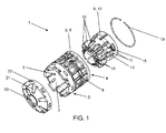
- FIG. 1 shows an exploded view of the embodiment of the device according to the invention 1 for protection against misfuelling and serves to briefly describe the basic components of the device 1. Details are in the FIG. 2 to FIG. 5 shown closer.
- a housing 2 comprises a closure element 9, a tensioning element 19 and a spring element 21, wherein the spring element 21 is designed in one piece with a separating element 20.
- the housing 2 has a tank-side housing end 3, a filling-side housing end 4 and a housing interior 5.
- the housing 2 has on its circumference three housing tabs 8.
- the housing tabs 8 are evenly distributed over the circumference of the housing 8.
- the closure element 9 has on its circumference three closure tabs 14, wherein the closure tabs 14 are distributed uniformly over the circumference of the closure element 9.
- the housing 2 is designed substantially cylindrical.
- the closure element 9 is substantially conical, in particular funnel-like executed.
- the closure element 9 tapers in the direction of the tank-side housing end 3.
- the closure element 9 has a plurality of incisions 11, whereby the closure element 9 is at least partially subdivided into a plurality of closure element segments 13.
- the Trennelement- / spring element composite 22 is designed annular and has a flap-like partition member 20 and a plurality of nose-like spring elements 21 on.
- the spring elements 21 are distributed substantially uniformly over the annular separation element / spring element composite 22.
- the separating element / spring element composite 22 can be connected to the tank-side housing end 3 via one and / or several clip connections.
- the spring elements 21 apply to the closure element 9 to an axial restoring force, whereby in the absence of the appropriate nozzle, the closure element 9 is pressed into a closure element home position.
- FIG. 2 is a sectional view (section AA) of the exemplary embodiment of the device 1 according to the invention shown.
- the closure element 9 is arranged coaxially in the housing 2 (in the housing interior 5).
- a housing tab 8 is in each case associated with a locking tab 14, wherein a respective locking tab 14, each with an associated housing tab 8 in the region of a closure tab end 15, the respective latching connection 17 is formed.
- the respective flap 14 associated housing tab 8 includes a locking device 18, wherein the respective locking tab 14 in the absence of the appropriate nozzle preferably engages the locking tab end 15 in the locking device 18 of the respectively associated housing tab 8 and so the respective latching connection 17 is formed.
- the locking tabs 14 and the associated housing tabs 8 are formed so that by inserting the appropriate nozzle all locking connections 17 between the respective locking tabs 14 and the respective associated housing tabs 8 are solved.
- the closure element 9 moves relative to the housing 2, axially in the direction of the tank-side housing end 3.
- the described movement is in FIG. 2 represented by an arrow.
- the appropriate nozzle can be inserted so far into the device 1 according to the invention that it opens the separator 20 (folds away in tank side direction) and a refueling of a tank is possible.
- the closure tabs 14 are formed so that they each have a protuberance 16 radially inwardly in the axial direction, wherein the protuberance 16 is formed so that upon insertion of the appropriate nozzle, the closure tabs 14 and the associated housing tabs 8 are moved radially outward and so a release of the respective snap-in connections 17 between the closure tabs 14 and the associated housing tabs 8 is effected.
- the respective latching connection 17 between the respective closure tabs 14 and the respective associated housing tabs 8 is reversibly released by inserting the suitable nozzle, ie that upon removal of the suitable nozzle from the device 1 again all closure tabs 14 with their respective associated housing tabs 8 a latching connection 17th train (lock).
- the closure element 9 has a plurality of sliding elements 10, wherein the sliding elements 10 are formed on an outer periphery of the closure element 12 in the direction of the housing 2.
- a sliding element 10 is associated with an axial slide guide on an inner circumference of the housing 7, wherein the respective slide member 10 in the respective slotted guide of the housing 2 is axially feasible.
- the sliding elements 10 are arranged on the closure element 9 (on the closure element segments 13) in the region of the tank-side housing end 3.
- the slide guide is designed so that the sliding elements 10 are movable radially outward, in particular only in the region of the tank-side housing end 3.
- stopper elements 23 are arranged in this embodiment of the device according to the invention also in the region of the tank-side housing end, the axial direction of the closure member 9 in the direction of the tank-side housing end 3 (arrow in FIG. 2 ) cooperate with the spring elements 21 and serve as a point of attack for the axial restoring force of the spring elements 21.
- FIG. 2 the funnel-shaped design of the closure element 9 can be seen.
- the diameter of the device 1 according to the invention is designed smaller than the diameter of the unsuitable dispensing gun.
- the unsuitable fuel nozzle is prevented at one point from the funnel-shaped closure element 9 from being introduced further in the direction of the separating element 20 (toward the tank-side housing end 3) and thus does not reach the separating element 20.
- the separating element remains in the separating element starting position.
- the flap-like separating element 20 can be moved by an appropriate nozzle into an open position - in this embodiment, the device 1 according to the invention in the tank-side direction can be folded away.
- the elastic clamping element 19 On an outer circumference of the housing 6, the elastic clamping element 19 is arranged, wherein the clamping element 19 applies a radial restoring force on the housing tabs 8, whereby the housing tabs 8 are held in a housing tab home position in the absence of the appropriate nozzle.
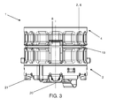
- FIG. 3 shows a longitudinal view of the exemplary embodiment of the device 1 according to the invention, wherein in particular a part of the outer circumference of the housing 6, the arrangement of the clamping element 19 and the arrangement of the housing tabs 8 can be seen.
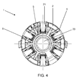
- FIG. 4 two cross-sectional views of the exemplary embodiment of the device 1 according to the invention are shown - in FIG. 4 a tank-side view and in FIG. 5 a filling-side view.
- Trennelement- / spring element composite 22 can be seen.
- the spring elements 21 and the flap-like separating element 20 are distributed uniformly over the circumference of the annular separating element / spring element composite 22.
- the nose-shaped spring elements 21 and the flap-like separating element 20 extend radially inwards.
- FIG. 5 In particular, the housing 2 and the coaxially arranged closure element 9, and the separating element 20 can be seen.
- the closure element segments 13 of the closure element 9 taper in the direction of the tank-side housing end 3.
Landscapes
- Engineering & Computer Science (AREA)
- Life Sciences & Earth Sciences (AREA)
- Sustainable Development (AREA)
- Sustainable Energy (AREA)
- Chemical & Material Sciences (AREA)
- Combustion & Propulsion (AREA)
- Transportation (AREA)
- Mechanical Engineering (AREA)
- Cooling, Air Intake And Gas Exhaust, And Fuel Tank Arrangements In Propulsion Units (AREA)
Abstract
Description
- Die vorliegende Erfindung betrifft eine Vorrichtung zum Schutz vor Fehlbetankung, insbesondere eines mit Diesel-Kraftstoff betriebenen Kraftfahrzeugs.
- Je nach Motorentyp benötigen Kraftfahrzeuge unterschiedliche Kraftstoffe, wobei eine Betankung des Kraftfahrzeugs mit einem nicht geeigneten Kraftstoff zu enormen Schäden des Kraftfahrzeugs führen kann.
- Herkömmliche Kraftfahrzeuge werden für gewöhnlich an Tankstellen betankt. Die Tanksäulen moderner Tankstellen bieten in der Regel mehrere Sorten von Kraftstoff an - zumeist Diesel und Benzin unterschiedlicher Klopffestigkeiten.
- Ein erster Schritt um einer Fehlbetankung vorzubeugen war die Einführung von Zapfventilen mit unterschiedlichen Durchmessern - so weisen derzeit beispielsweise Diesel-Zapfventile einen Durchmesser von ≥ 23,6 mm auf, Benzin-Zapfventile hingegen einen Durchmesser von bis zu 21,3 mm.
- Zapfventile werden umgangssprachlich auch Zapfpistolen genannt und sind über einen Schlauch mit der Tanksäule verbunden.
- Durch die Anpassung des Durchmessers des Kraftfahrzeug-Tankstutzens (Tank-Einfüllrohrs) kann somit zumindest bei benzinbetriebenen Kraftfahrzeugen auf einfache Art und Weise eine Fehlbetankung mit Diesel verhindert werden.
- Die Gefahr versehentlich Benzin, das durch eine im Vergleich zu einer Diesel-Zapfpistole im Durchmesser kleineren Benzin-Zapfpistole gefördert wird, in ein mit Diesel betriebenes Fahrzeug zu tanken bleibt jedoch bestehen.
- Der allgemeine Stand der Technik beschreibt zu dieser Problematik eine Vielzahl unterschiedlicher Lösungen um eine Fehlbetankung eines dieselbetriebenen Kraftfahrzeugs mit Benzin zu verhindern.
- Die
DE 103 20 992 A1 beschreibt zum Beispiel eine derartige Vorrichtung, wobei eine Zusatzvorrichtung im Tankstutzen eines Fahrzeugs angebracht wird. Die ringförmige Zusatzvorrichtung bedingt eine Verkleinerung des Durchmessers des Tankstutzens mittels mehrerer am Umfang angeordneter Radialelemente. Der Durchmesser ist im Bereich der Radialelemente kleiner als der Durchmesser der geeigneten Zapfpistole. Die Zusatzvorrichtung ist nach oben zur Öffnung hin konisch ausgeführt, so dass die geeignete Zapfpistole leicht und einfach angeschnäbelt werden kann. Bei weiterem Einführen der geeigneten Zapfpistole werden die Radialelemente so verformt, gekippt oder bewegt, dass sich die Öffnung aufweitet und die Zapfpistole ganz in das Tankrohr eingeschoben werden kann. Die elastische oder gelenkige Bewegung der Radialelemente verursacht eine Kipp- bzw. Rotationsbewegung von Widerhaken an der Vorrichtung. Eine nicht geeignete Zapfpistole bleibt an den Widerhaken hängen und kann nicht weiter in das Tankrohr eingeführt werden. - Das Dokument
DE 101 57 090 C1 beschreibt ebenso eine Anordnung zum Verhindern des Betankens eines Dieselfahrzeuges mit bleifreien Benzin. Im Tankstutzen ist dabei ein Sperrhebel vorgesehen, der zwischen einer Ruhestellung und einer Betankstellung hin und her bewegbar ist. Der Sperrhebel ist an seinem der Tanköffnung abgekehrten Ende mit einer Sperrlasche versehen, die in Ruhelage in den Querschnitt des Tankstutzens hineinragt und ein Einführen einer nicht geeigneten Zapfpistole in den Tank verhindert. Der Sperrhebel weist an seinem der Tanköffnung zugewandten Ende einen Betätigungsfortsatz auf, der durch eine geeignete Zapfpistole betätigbar ist und mittels dem der Sperrhebel in eine Betankungsstellung bewegt wird. - Weitere Ausführungsbeispiele von Vorrichtungen, die sich mit dieser Thematik beschäftigen sind unter anderem in der Dokumenten
DE202005021965 undEP1790517 offenbart. - Es ist Aufgabe der Erfindung eine zu den bekannten Lösungen alternative Vorrichtung zum Schutz vor Fehlbetankung, insbesondere eines dieselbetriebenen Kraftfahrzeugs, vorzuschlagen.
- Die Lösung der Aufgabe erfolgt erfindungsgemäß durch eine Vorrichtung zum Schutz vor Fehlbetankung umfassend ein Gehäuse und ein im Gehäuse angeordnetes Verschlusselement, wobei das Verschlusselement umfänglich zumindest eine Verschlusslasche aufweist und das Gehäuse zumindest eine der Verschlusslasche zugeordnete Gehäuselasche aufweist, wobei die Verschlusslasche mit der zugeordneten Gehäuselasche eine Rastverbindung ausbildet, wobei die Verschlusslasche und die zugeordnete Gehäuselasche so ausgebildet sind, dass die Rastverbindung durch Einführen einer geeigneten Zapfpistole reversibel gelöst wird, so dass das Verschlusselement daraufhin relativ zum Gehäuse axial bewegbar ist, wodurch ein Trennelement öffenbar ist und eine Betankung ermöglicht wird.
- Bei der geeigneten Zapfpistole handelt es sich insbesondere um eine Zapfpistole in für Diesel-Kraftstoffe üblicher Form.
- Bei einer nicht geeigneten Zapfpistole handelt es sich um eine im Vergleich zur Diesel-Zapfpistole im Durchmesser kleinere Zapfpistole, wie dies beispielsweise bei Zapfpistolen für Benzin-Kraftstoffe der Fall ist.
- Eine Verwendung der erfindungsgemäßen Vorrichtung ist jedoch ebenso in nicht vorwiegend automotiv genutzten Tanksystemen und/oder Tankarten, wie beispielsweise Heizöltanks, vorstellbar.
- Die erfindungsgemäße Vorrichtung umfasst das Gehäuse, wobei das Gehäuse ein tankseitiges Gehäuseende, ein befüllungsseitiges Gehäuseende, sowie einen Gehäuseinnenraum aufweist.
- Das Gehäuse ist bevorzugt aus Kunststoff gefertigt. Ein aus einem metallischen Werkstoff gefertigtes Gehäuse ist ebenso anwendbar.
- Das Verschlusselement ist erfindungsgemäß im Gehäuse, d.h. im Gehäuseinnenraum, angeordnet, wodurch unter anderem eine kompakte Bauweise der erfindungsgemäßen Vorrichtung erreicht wird.
- Das Verschlusselement ist bevorzugt aus Kunststoff gefertigt. Ein aus einem metallischen Werkstoff gefertigtes Verschlusselement ist ebenso anwendbar.
- Gemäß der vorliegenden Erfindung weist das Verschlusselement an seinem Umfang zumindest eine Verschlusslasche auf, wobei die Verschlusslasche an dem Umfang des Verschlusselements angeordnet ist.
- Die Verschlusslasche ist bevorzugt aus dem gleichen Material wie das Verschlusselement gefertigt.
- Des Weiteren weist das Gehäuse entsprechend der vorliegenden Erfindung an seinem Umfang zumindest eine Gehäuselasche auf, wobei eine Gehäuselasche einer Verschlusslasche zugeordnet ist.
- Die Gehäuselasche ist bevorzugt aus dem gleichen Material wie das Gehäuse gefertigt.
- Erfindungsgemäß bildet die Verschlusslasche mit der zugeordneten Gehäuselasche die Rastverbindung aus.
- Die Verschlusslasche und die zugeordnete Gehäuselasche sind dabei so ausgebildet, dass durch Einführen der geeigneten Zapfpistole die Rastverbindung zwischen der Verschlusslasche und der zugeordneten Gehäuselasche gelöst wird. Bei weiterem Einführen der geeigneten Zapfpistole in Richtung des tankseitigen Gehäuseendes bewegt sich das Verschlusselement relativ zum Gehäuse, axial in Richtung des tankseitigen Gehäuseendes. Durch diese Bewegung kann die geeignete Zapfpistole so weit in die erfindungsgemäße Vorrichtung eingeführt werden, dass sie das Trennelement öffnet und eine Betankung eines Tanks möglich ist.
- Axial bedeutet in Richtung oder parallel zur Längsachse des zylindrischen Gehäuses. Radial bedeutet in Richtung oder parallel zur Querachse des zylindrischen Gehäuses.
- Die Rastverbindung zwischen der Verschlusslasche und der zugeordneten Gehäuselasche wird durch Einführen der geeigneten Zapfpistole reversibel gelöst, d.h., dass bei Entfernung der geeigneten Zapfpistole aus der Vorrichtung die Verschlusslasche mit der zugeordneten Gehäuselasche wieder die Rastverbindung ausbildet.
- Weiterbildungen der Erfindung sind in den abhängigen Ansprüchen, der Beschreibung sowie den beigefügten Zeichnungen angegeben.
- Besonders bevorzugt weist das Verschlusselement zumindest drei Verschlusslaschen auf, wobei die drei Verschlusslaschen gleichmäßig über den Umfang des Verschlusselements verteilt sind.
- Besonders bevorzugt weist das Gehäuse an seinem Umfang (gleichmäßig verteilt) zumindest drei Gehäuselaschen auf, wobei jeweils eine Gehäuselasche jeweils einer Verschlusslasche zugeordnet ist.
- Bevorzugt sind das Gehäuse und das im Gehäuse angeordnete Verschlusselement koaxial angeordnet.
- In einer vorteilhaften Ausführungsvariante der vorliegenden Erfindung ist das Gehäuse im Wesentlichen zylindrisch und das Verschlusselement im Wesentlichen konisch, insbesondere trichterartig, ausgeführt. In einer weiteren vorteilhaften Ausführungsvariante verjüngt sich das Verschlusselement in Richtung des tankseitigen Gehäuseendes.
- "Quer"-Bezeichnungen beziehen sich im Folgenden immer auf die Lage der Querachse des zylindrischen Gehäuses. "Längs"-Bezeichnungen beziehen sich dementsprechend auf die Lage der Längsachse des zylindrischen Gehäuses.
- Über die trichterartige Ausbildung des Verschlusselements kann konstruktiv auf einfache Art und Weise eine Verkleinerung des Durchmessers der erfindungsgemäßen Vorrichtung erreicht werden.
- Ebenso vorteilhaft ist eine im Wesentlichen zylindrische Ausbildung des Verschlusselements, wobei konstruktiv am Innenumfang des Verschlusselements sich in Richtung des Gehäuseendes verjüngende Rippen vorgesehen sind.
- In einer besonders bevorzugten Ausführungsform der vorliegenden Erfindung ist das Trennelement am tankseitigen Gehäuseende angeordnet und so ausgebildet, dass in einer Trennelement-Ausgangsposition eine Trennung des Gehäuseinnenraums und eines Tanks ermöglicht wird, so dass das Befüllen des Tanks mit einer Zapfpistole nicht möglich ist.
- Die Trennelement-Ausgangsposition beschreibt somit eine geschlossene Position des Trennelements. Das Trennelement ist dabei bevorzugt quer (normal auf die Längsachse des Gehäuses) angeordnet.
- Durch die Verkleinerung des Durchmessers der erfindungsgemäßen Vorrichtung mittels beispielsweise des trichterförmigen Verschlusselements wird mitunter eine missbräuchliche Betankung durch eine nicht geeignete Zapfpistole verhindert, indem der Durchmesser der erfindungsgemäßen Vorrichtung kleiner gestaltet ist als der Durchmesser der nicht geeigneten Zapfpistole. Die nicht geeignete Zapfpistole wird je nach Durchmesser an einer Stelle des trichterförmigen Verschlusselements am weiteren Einführen in Richtung Trennelement (in Richtung tankseitiges Gehäuseende) gehindert und erreicht das Trennelement somit nicht. Das Trennelement verbleibt in der Trennelement-Ausgangsposition.
- Dadurch, dass das Trennelement in der Trennelement-Ausgangsposition verbleibt kommt es selbst bei einem Versuch der Betankung des Tanks über eine nicht geeignete Zapfpistole aufgrund der in dem Zapfventil (Zapfpsitole) standardmäßig integrierten Zapfventilautomatik zu einem sofortigen Abschalten der Zapfpistole. Das Trennelement ist jedoch durch eine geeignete Zapfpistole in eine geöffnete Position bewegbar - aus der Trennelement-Ausgangsposition herausbewegbar.
- Besonders bevorzugt ist das Trennelement klappenartig ausgeführt.
- Des Weiteren besonders vorteilhaft ist das Trennelement aus einem elektrisch leitfähigem Material, insbesondere einem metallischen Werkstoff, wie beispielsweise Federstahl, gefertigt, wodurch das Trennelement als ein metallischer Kontaktpunkt für die geeignete Zapfpistole dient und somit als Erdung wirkt.
- Vorteilhafterweise ist das Verschlusselement zumindest teilweise elastisch ausgeführt.
- Gemäß einer weiteren bevorzugten Ausführungsform der Erfindung weist das Verschlusselement, insbesondere im Bereich des tankseitigen Gehäuseendes, mehrere Einschnitte auf, wodurch das Verschlusselement zumindest teilweise in mehrere Verschlusselement-Segmente unterteilt wird. Aufgrund der elastischen Ausbildung des Verschlusselements und der Ausbildung mehrerer Verschlusselement-Segmente ist eine radiale Bewegung des Verschlusselements und/oder der Verschlusselement Segmente möglich.
- Vorteilhafterweise ist die Verschlusslasche und die Gehäuselasche elastisch ausgebildet.
- In einer besonders bevorzugten Ausführungsform der Erfindung ist an einem Außenumfang des Gehäuses ein elastisches Spannelement angeordnet, wobei das Spannelement auf die Gehäuselasche eine radiale Rückstellkraft aufbringt, wodurch in Abwesenheit der geeigneten Zapfpistole die Gehäuselasche in einer Gehäuselaschen-Ausgangsposition gehalten werden.
- Die Gehäuselaschen-Ausgangsposition beschreibt somit eine Position, in der die Verschlusslasche mit der zugeordneten Gehäuselaschen die jeweiligen Rastverbindungen ausbilden.
- Vorteilhafterweise umfasst die der Verschlusslasche zugeordnete Gehäuselasche eine Rastvorrichtung, wobei die Verschlusslasche in Abwesenheit der geeigneten Zapfpistole bevorzugt an einem Verschlusslaschenende in die Rastvorrichtung der zugeordneten Gehäuselasche einrastet und so die Rastverbindung gebildet wird.
- Die Verschlusslasche ist in einer besonders vorteilhaften Ausführungsvariante der erfindungsgemäßen Vorrichtung so ausgebildet, dass sie in axialer Richtung eine Ausstülpung radial nach innen aufweist, wobei die Ausstülpung so ausgebildet ist, dass bei Einführen der geeigneten Zapfpistole die Verschlusslasche und die zugeordnete Gehäuselasche radial nach außen bewegt werden und so ein Lösen der Rastverbindung zwischen der Verschlusslasche und der zugeordneten Gehäuselasche bewirkt wird.
- "Nach innen" bedeutet in Richtung zentraler Längsachse des zylindrischen Gehäuses - "nach außen" beschreibt die dazu entgegengesetzte Richtung.
- Gemäß einer weiteren besonders bevorzugten Ausführungsform der Erfindung weist das Verschlusselement mehrere Gleitelemente auf, wobei die Gleitelemente an einem Außenumfang des Verschlusselements in Richtung des Gehäuses ausgebildet sind. Dabei ist erfindungsgemäß jeweils einem Gleitelement eine axiale Kulissenführung an einem Innenumfang des Gehäuses zugeordnet, wobei das jeweilige Gleitelement in der jeweiligen Kulissenführung des Gehäuses axial führbar ist.
- Die Gleitelemente sind besonders bevorzugt am Verschlusselement im Bereich des tankseitigen Gehäuseendes angeordnet.
- Die Kulissenführung ist vorteilhafterweise derart ausgebildet, dass die Gleitelemente insbesondere lediglich im Bereich des tankseitigen Gehäuseendes radial nach außen bewegbar sind.
- Besonders bevorzugt weist die erfindungsgemäße Vorrichtung im Bereich des tankseitigen Gehäuseendes zumindest ein Federelement auf, wobei das Federelement auf das Verschlusselement eine axiale Rückstellkraft aufbringt, wodurch in Abwesenheit der geeigneten Zapfpistole das Verschlusselement in eine Verschlusselement-Ausgangsposition gedrückt wird.
- In der Verschlusselement-Ausgangsposition bildet die Verschlusslasche des Verschlusselements mit der ihr zugeordneten Gehäuselasche die Rastverbindung aus.
- In einer vorteilhaften Ausführungsvariante ist das Federelement einteilig mit dem Trennelement ausgebildet, wodurch eine Bauteilreduktion und eine kompaktere Bauweise der erfindungsgemäßen Vorrichtung erzielt werden.
- Durch die im gesamten kompakte und einfache Bauweise ist die erfindungsgemäße Vorrichtung vorteilhafterweise durch einen Befüllungssockel eines Tankstutzens des Tanks montier- und demontierbar. Eine Befestigung im Tankstutzen erfolgt dabei bevorzugt mittels eines Bajonettverschlusses zwischen dem Gehäuse der erfindungsgemäßen Vorrichtung und dem Tankstutzen, wobei eine Anwendung in jeglicher Art von Tankstutzen möglich ist.
- Die Erfindung wird im Folgenden beispielhaft unter Bezugnahme auf die Zeichnungen beschrieben.
- Fig. 1
- zeigt eine Explosionszeichnung einer beispielhaften Ausführungsvariante der erfindungsgemäßen Vorrichtung
- Fig. 2
- zeigt eine Schnittansicht (A-A) der beispielhaften Ausführungsvariante in
FIG. 1 - FIG. 3
- zeigt eine Längs-Darstellung der beispielhaften Ausführungsvariante in
FIG. 1 - FIG. 4
- zeigt eine tankseitige Querschnitt-Darstellung der beispielhaften Ausführungsvariante in
FIG. 1 - FIG. 5
- zeigt eine befüllungsseitige Querschnitt-Darstellung der beispielhaften Ausführungsvariante in
FIG. 1 - Unter Bezugnahme auf die
FIG. 1 bis FIG. 5 wird im Folgenden eine mögliche Ausführungsvariante der erfindungsgemäßen Vorrichtung 1 beschrieben. -
FIG. 1 zeigt eine Explosionsdarstellung der Ausführungsvariante der erfindungsgemäßen Vorrichtung 1 zum Schutz vor Fehlbetankung und dient der kurzen Beschreibung der grundlegenden Bauteile der Vorrichtung 1. Einzelheiten werden in denFIG. 2 bis FIG. 5 näher gezeigt. - Die in
FIG. 1 gezeigte Vorrichtung 1 umfasst ein Gehäuse 2 ein Verschlusselement 9, ein Spannelement 19 und ein Federelement 21, wobei das Federelement 21 einteilig mit einem Trennelement 20 ausgeführt ist. - Das Gehäuse 2 weist ein tankseitiges Gehäuseende 3, ein befüllungsseitiges Gehäuseende 4 und einen Gehäuseinnenraum 5 auf.
- Das Gehäuse 2 weist an seinem Umfang drei Gehäuselaschen 8 auf. Die Gehäuselaschen 8 sind gleichmäßig über den Umfang des Gehäuses 8 verteilt.
- Das Verschlusselement 9 weist an seinem Umfang drei Verschlusslaschen 14 auf, wobei die Verschlusslaschen 14 gleichmäßig über den Umfang des Verschlusselements 9 verteilt sind.
- Das Gehäuse 2 ist im Wesentlichen zylindrisch ausgeführt.
- Das Verschlusselement 9 ist im Wesentlichen konisch, insbesondere trichterartig, ausgeführt. Das Verschlusselement 9 verjüngt sich in Richtung des tankseitigen Gehäuseendes 3.
- Das Verschlusselement 9 weist mehrere Einschnitte 11 auf, wodurch das Verschlusselement 9 zumindest teilweise in mehrere Verschlusselement-Segmente 13 unterteilt wird.
- Im Bereich der Verschlusselement-Segmente 13 sind mehrere Gleitelemente 10 angeordnet.
- Der Trennelement-/Federelement-Verbund 22 ist kreisringartig ausgeführt und weist ein klappenartiges Trennelement 20 und mehrere nasenartige Federelemente 21 auf. Die Federelemente 21 sind im Wesentlichen gleichmäßig über den kreisringartigen Trennelement-/Federelement-Verbund 22 verteilt.
- Der Trennelement-/Federelement-Verbund 22 ist über eine und/oder mehrere Klippverbindungen mit dem tankseitigen Gehäuseende 3 verbindbar.
- Die Federelemente 21 bringen auf das Verschlusselement 9 eine axiale Rückstellkraft auf, wodurch in Abwesenheit der geeigneten Zapfpistole das Verschlusselement 9 in eine Verschlusselement-Ausgangsposition gedrückt wird.
- In
FIG. 2 ist eine Schnittansicht (Schnitt A-A) der beispielhaften Ausführungsform der erfindungsgemäßen Vorrichtung 1 dargestellt. - Das Verschlusselement 9 ist koaxial im Gehäuse 2 (im Gehäuseinnenraum 5) angeordnet.
- Jeweils eine Gehäuselasche 8 ist jeweils einer Verschlusslasche 14 zugeordnet, wobei jeweils eine Verschlusslasche 14 mit jeweils einer zugeordneten Gehäuselasche 8 im Bereich eines Verschlusslaschenendes 15 die jeweilige Rastverbindung 17 ausbildet.
- Die der jeweiligen Verschlusslasche 14 zugeordnete Gehäuselasche 8 umfasst eine Rastvorrichtung 18, wobei die jeweilige Verschlusslasche 14 in Abwesenheit der geeigneten Zapfpistole bevorzugt an dem Verschlusslaschenende 15 in die Rastvorrichtung 18 der jeweils zugeordneten Gehäuselasche 8 einrastet und so die jeweilige Rastverbindung 17 gebildet wird.
- Die Verschlusslaschen 14 und die zugeordneten Gehäuselaschen 8 sind dabei so ausgebildet, dass durch Einführen der geeigneten Zapfpistole sämtliche Rastverbindungen 17 zwischen den jeweiligen Verschlusslaschen 14 und den jeweils zugeordneten Gehäuselaschen 8 gelöst werden. Bei weiterem Einführen der geeigneten Zapfpistole in Richtung des tankseitigen Gehäuseendes 3 bewegt sich das Verschlusselement 9 relativ zum Gehäuse 2, axial in Richtung des tankseitigen Gehäuseendes 3. Die beschriebene Bewegung ist in
FIG. 2 mittels eines Pfeils dargestellt. Durch diese Bewegung kann die geeignete Zapfpistole so weit in die erfindungsgemäße Vorrichtung 1 eingeführt werden, dass sie das Trennelement 20 öffnet (in tankseitige Richtung wegklappt) und eine Betankung eines Tanks möglich ist. - Die Verschlusslaschen 14 sind so ausgebildet, dass sie jeweils in axialer Richtung eine Ausstülpung 16 radial nach innen aufweisen, wobei die Ausstülpung 16 so ausgebildet ist, dass bei Einführen der geeigneten Zapfpistole die Verschlusslaschen 14 und die zugeordneten Gehäuselaschen 8 radial nach außen bewegt werden und so ein Lösen der jeweiligen Rastverbindungen 17 zwischen den Verschlusslaschen 14 und den zugeordneten Gehäuselaschen 8 bewirkt wird.
- Die jeweilige Rastverbindung 17 zwischen den jeweiligen Verschlusslaschen 14 und den jeweils zugeordneten Gehäuselaschen 8 wird durch Einführen der geeigneten Zapfpistole reversibel gelöst, d.h., dass bei Entfernung der geeigneten Zapfpistole aus der Vorrichtung 1 wieder sämtliche Verschlusslaschen 14 mit den ihnen jeweils zugeordneten Gehäuselaschen 8 eine Rastverbindung 17 ausbilden (verrasten).
- Das Verschlusselement 9 weist mehrere Gleitelemente 10 auf, wobei die Gleitelemente 10 an einem Außenumfang des Verschlusselements 12 in Richtung des Gehäuses 2 ausgebildet sind. Jeweils einem Gleitelement 10 ist eine axiale Kulissenführung an einem Innenumfang des Gehäuses 7 zugeordnet, wobei das jeweilige Gleitelement 10 in der jeweiligen Kulissenführung des Gehäuses 2 axial führbar ist.
- Die Gleitelemente 10 sind am Verschlusselement 9 (an den Verschlusselement-Segmenten 13) im Bereich des tankseitigen Gehäuseendes 3 angeordnet.
- Die Kulissenführung ist so ausgebildet, dass die Gleitelemente 10 insbesondere lediglich im Bereich des tankseitigen Gehäuseendes 3 radial nach außen bewegbar sind.
- Am Verschlusselement 9 sind bei diesem Ausführungsbeispiel der erfindungsgemäßen Vorrichtung 1 zudem im Bereich des tankseitigen Gehäuseendes 3 Stopperelemente 23 angeordnet, die bei axialer Bewegung des Verschlusselements 9 in Richtung des tankseitigen Gehäuseendes 3 (Pfeilrichtung in
FIG. 2 ) mit den Federelementen 21 zusammenwirken und als Angriffspunkt für die axiale Rückstellkraft der Federelemente 21 dienen. - In
FIG. 2 ist die trichterförmige Ausbildung des Verschlusselements 9 erkennbar. - Durch die Verkleinerung des Durchmessers der erfindungsgemäßen Vorrichtung 1 mittels des trichterförmigen Verschlusselements 9 wird mitunter eine missbräuchliche Betankung durch eine nicht geeignete Zapfpistole verhindert, indem der Durchmesser der erfindungsgemäßen Vorrichtung 1 kleiner gestaltet ist als der Durchmesser der nicht geeigneten Zapfpistole. Die nicht geeignete Zapfpistole wird je nach Durchmesser an einer Stelle des trichterförmigen Verschlusselements 9 am weiteren Einführen in Richtung Trennelement 20 (in Richtung tankseitiges Gehäuseende 3) gehindert und erreicht das Trennelement 20 somit nicht. Das Trennelement verbleibt in der Trennelement-Ausgangsposition.
- Das klappenartige Trennelement 20 ist durch eine geeignete Zapfpistole in eine geöffnete Position bewegbar - in diesem Ausführungsbeispiel der erfindungsgemäßen Vorrichtung 1 in tankseitige Richtung wegklappbar.
- An einem Außenumfang des Gehäuses 6 ist das elastische Spannelement 19 angeordnet, wobei das Spannelement 19 auf die Gehäuselaschen 8 eine radiale Rückstellkraft aufbringt, wodurch in Abwesenheit der geeigneten Zapfpistole die Gehäuselaschen 8 in einer Gehäuselaschen-Ausgangsposition gehalten werden.
-
FIG. 3 zeigt eine Längs-Darstellung der beispielhaften Ausführungsvariante der erfindungsgemäßen Vorrichtung 1, wobei insbesondere ein Teil des Außenumfangs des Gehäuses 6, die Anordnung des Spannelements 19 und die Anordnung einer der Gehäuselaschen 8 erkennbar ist. - In
FIG 4 . undFIG. 5 sind zwei Querschnitt-Darstellungen der beispielhaften Ausführungsvariante der erfindungsgemäßen Vorrichtung 1 dargestellt - inFIG. 4 eine tankseitige Ansicht und inFIG. 5 eine befüllungsseitige Ansicht. - In
FIG. 4 ist insbesondere der Trennelement-/Federelementverbund 22 erkennbar. Die Federelemente 21 und das klappenartige Trennelement 20 sind gleichmäßig über den Umfang des kreisringförmigen Trennelement-/Federelementverbunds 22 verteilt. Die nasenförmigen Federelemente 21 und das klappenartige Trennelement 20 erstrecken sich radial nach innen. - In
FIG 5 sind insbesondere das Gehäuse 2 und das koaxial angeordnete Verschlusselement 9, sowie das Trennelement 20 ersichtlich. Die Verschlusselement-Segmente 13 des Verschlusselements 9 verjüngen sich in Richtung des tankseitigen Gehäuseendes 3. -
- 1
- Vorrichtung
- 2
- Gehäuse
- 3
- Tankseitiges Gehäuseende
- 4
- Befüllungsseitiges Gehäuseende
- 5
- Gehäuseinnenraum
- 6
- Außenumfang des Gehäuses
- 7
- Innenumfang des Gehäuses
- 8
- Gehäuselasche
- 9
- Verschlusselement
- 10
- Gleitelement
- 11
- Einschnitt
- 12
- Außenumfang des Verschlusselements
- 13
- Verschlusselement-Segment
- 14
- Verschlusslasche
- 15
- Verschlusslaschenende
- 16
- Ausstülpung
- 17
- Rastverbindung
- 18
- Rastvorrichtung
- 19
- Spannelement
- 20
- Trennelement
- 21
- Federelement
- 22
- Trennelement-/Federelement-Verbund
- 23
- Stopperelement
Claims (19)
- Vorrichtung (1) zum Schutz vor Fehlbetankung umfassend ein Gehäuse (2) und ein im Gehäuse (2) angeordnetes Verschlusselement (9), wobei das Verschlusselement (9) umfänglich zumindest eine Verschlusslasche (14) aufweist und das Gehäuse (2) zumindest eine der Verschlusslasche (14) zugeordnete Gehäuselasche (8) aufweist,
dadurch gekennzeichnet , dass die Verschlusslasche (14) mit der zugeordneten Gehäuselasche (8) eine Rastverbindung (17) ausbildet, wobei die Verschlusslasche (14) und die zugeordnete Gehäuselasche (8) so ausgebildet sind, dass die Rastverbindung (17) durch Einführen einer geeigneten Zapfpistole reversibel gelöst wird, so dass das Verschlusselement (9) daraufhin relativ zum Gehäuse (2) axial bewegbar ist, wodurch ein Trennelement (20) öffenbar ist und eine Betankung ermöglicht wird. - Vorrichtung (1) zum Schutz vor Fehlbetankung nach Anspruch 1,
dadurch gekennzeichnet, dass das Verschlusselement (9) umfänglich zumindest 3 Verschlusslaschen (14) aufweist und das Gehäuse (2) zumindest drei den Verschlusslaschen (14) zugeordnete Gehäuselaschen (8) aufweist. - Vorrichtung (1) zum Schutz vor Fehlbetankung nach Anspruch 1 oder 2,
dadurch gekennzeichnet , dass das Gehäuse (2) und das im Gehäuse (2) angeordnete Verschlusselement (9) koaxial angeordnet sind. - Vorrichtung (1) zum Schutz vor Fehlbetankung nach einem der Ansprüche 1 bis 3,
dadurch gekennzeichnet, dass das Gehäuse (2) im Wesentlichen zylindrisch ausgebildet ist, wobei das Gehäuse (2) ein tankseitiges Gehäuseende (3), ein befüllungsseitiges Gehäuseende (4) und einen Gehäuseinnenraum (5) aufweist. - Vorrichtung (1) zum Schutz vor Fehlbetankung nach einem der Ansprüche 1 bis 4,
dadurch gekennzeichnet , dass das Trennelement (20) am tankseitigen Gehäuseende (3) angeordnet ist und so ausgebildet ist, dass in einer Trennelement-Ausgangsposition eine Trennung des Gehäuseinnenraums (5) und eines Tanks ermöglicht wird, so dass das Befüllen des Tanks mit einer Zapfpistole nicht möglich ist. - Vorrichtung (1) zum Schutz vor Fehlbetankung nach einem der vorhergehenden Ansprüche,
dadurch gekennzeichnet , dass das Trennelement (20) klappenartig ausgeführt ist. - Vorrichtung (1) zum Schutz vor Fehlbetankung nach einem der vorhergehenden Ansprüche,
dadurch gekennzeichnet , dass das Trennelement (20) durch eine geeignete Zapfpistole in eine geöffnete Position bewegbar ist. - Vorrichtung (1) zum Schutz vor Fehlbetankung nach einem der vorhergehenden Ansprüche,
dadurch gekennzeichnet , dass das Verschlusselement (9) im Wesentlichen konisch, insbesondere trichterartig, ausgeführt ist, wobei sich das Verschlusselement (9) in Richtung des tankseitigen Gehäuseendes (3) verjüngt. - Vorrichtung (1) zum Schutz vor Fehlbetankung nach einem der vorhergehenden Ansprüche,
dadurch gekennzeichnet , dass das Verschlusselement (9) mehrere Einschnitte (11) aufweist, wodurch das Verschlusselement (9) zumindest teilweise in mehrere Verschlusselement-Segmente (13) unterteilt wird. - Vorrichtung (1) zum Schutz vor Fehlbetankung nach einem der vorhergehenden Ansprüche,
dadurch gekennzeichnet , dass das Verschlusselement (9) zumindest teilweise elastisch ausgeführt ist. - Vorrichtung (1) zum Schutz vor Fehlbetankung nach einem der vorhergehenden Ansprüche,
dadurch gekennzeichnet , dass die Verschlusslasche (14) und die Gehäuselasche (8) elastisch ausgebildet sind. - Vorrichtung (1) zum Schutz vor Fehlbetankung nach einem der vorhergehenden Ansprüche,
dadurch gekennzeichnet , dass an einem Außenumfang des Gehäuses (6) ein elastisches Spannelement (19) angeordnet ist, wobei das Spannelement (19) auf die Gehäuselasche (8) eine radiale Rückstellkraft aufbringt, wodurch in Abwesenheit einer geeigneten Zapfpistole die Gehäuselasche (8) in einer Gehäuselaschen-Ausgangsposition gehalten werden. - Vorrichtung (1) zum Schutz vor Fehlbetankung nach einem der vorhergehenden Ansprüche,
dadurch gekennzeichnet , dass die der Verschlusslasche (14) zugeordnete Gehäuselasche (8) eine Rastvorrichtung (18) aufweist, wobei die Verschlusslasche (14) in Abwesenheit einer geeigneten Zapfpistole bevorzugt an einem Verschlusslaschenende (15) in die Rastvorrichtung (18) der zugeordneten Gehäuselasche (8) einrastet und so die Rastverbindung (17) ausgebildet wird. - Vorrichtung (1) zum Schutz vor Fehlbetankung nach einem der vorhergehenden Ansprüche,
dadurch gekennzeichnet , dass die Verschlusslasche (14) so ausgebildet sind, dass sie in Richtung der Längsachse der Vorrichtung (1) eine Ausstülpung (16) radial nach innen aufweist, wobei die Ausstülpung (16) so ausgebildet ist, dass bei Einführen einer geeigneten Zapfpistole in die Vorrichtung (1) die Verschlusslasche (14) und die zugeordnete Gehäuselasche (8) radial nach außen bewegt werden und so ein Lösen der jeweiligen Rastverbindungen (17) zwischen den Verschlusslasche (14) und den zugeordnete Gehäuselaschen (8) bewirkt wird. - Vorrichtung (1) zum Schutz vor Fehlbetankung nach einem der vorhergehenden Ansprüche,
dadurch gekennzeichnet, dass das Verschlusselement (9) mehrere Gleitelemente (10) aufweist, wobei die Gleitelemente (10) an einem Außenumfang des Verschlusselements (12) in Richtung des Gehäuses (2) ausgebildet sind. - Vorrichtung (1) zum Schutz vor Fehlbetankung nach Anspruch 14,
dadurch gekennzeichnet , dass jeweils einem Gleitelement (10) eine axiale Kulissenführung an einem Innenumfang des Gehäuses (7) zugeordnet ist, wobei das jeweilige Gleitelement (10) in der jeweiligen Kulissenführung des Gehäuses (2) axial führbar ist. - Vorrichtung (1) zum Schutz vor Fehlbetankung nach Anspruch 15,
dadurch gekennzeichnet , dass die Kulissenführung derart ausgebildet ist, dass die Gleitelemente (10) insbesondere lediglich im Bereich des tankseitigen Gehäuseendes (3) radial nach außen bewegbar sind. - Vorrichtung (1) zum Schutz vor Fehlbetankung nach einem der vorhergehenden Ansprüche,
dadurch gekennzeichnet , dass im Bereich des tankseitigen Gehäuseendes (3) zumindest ein Federelement (21) angeordnet ist, wobei das Federelement (21) auf das Verschlusselement (9) eine axiale Rückstellkraft aufbringt, wodurch in Abwesenheit einer geeigneten Zapfpistole das Verschlusselement (9) in eine Verschlusselement-Ausgangsposition gedrückt wird. - Vorrichtung (1) zum Schutz vor Fehlbetankung nach Anspruch 14, dadurch gekennzeichnet , dass das Federelement (21) einteilig mit dem Trennelement (20) ausgebildet ist.
Priority Applications (3)
| Application Number | Priority Date | Filing Date | Title |
|---|---|---|---|
| EP14195241.6A EP3025893B1 (de) | 2014-11-27 | 2014-11-27 | Vorrichtung zum schutz vor fehlbetankung |
| CN201510836582.1A CN105644350B (zh) | 2014-11-27 | 2015-11-26 | 用于防止误加燃料的设备 |
| US14/953,522 US9783047B2 (en) | 2014-11-27 | 2015-11-30 | Device for protection against incorrect refuelling |
Applications Claiming Priority (1)
| Application Number | Priority Date | Filing Date | Title |
|---|---|---|---|
| EP14195241.6A EP3025893B1 (de) | 2014-11-27 | 2014-11-27 | Vorrichtung zum schutz vor fehlbetankung |
Publications (2)
| Publication Number | Publication Date |
|---|---|
| EP3025893A1 true EP3025893A1 (de) | 2016-06-01 |
| EP3025893B1 EP3025893B1 (de) | 2017-03-01 |
Family
ID=52103031
Family Applications (1)
| Application Number | Title | Priority Date | Filing Date |
|---|---|---|---|
| EP14195241.6A Not-in-force EP3025893B1 (de) | 2014-11-27 | 2014-11-27 | Vorrichtung zum schutz vor fehlbetankung |
Country Status (3)
| Country | Link |
|---|---|
| US (1) | US9783047B2 (de) |
| EP (1) | EP3025893B1 (de) |
| CN (1) | CN105644350B (de) |
Families Citing this family (6)
| Publication number | Priority date | Publication date | Assignee | Title |
|---|---|---|---|---|
| US10000117B2 (en) | 2012-02-17 | 2018-06-19 | Stant Usa Corp. | Filler neck closure assembly |
| CA2973861C (en) * | 2015-01-30 | 2021-05-11 | Martinrea Industries, Inc. | Capless automotive fueling system with miss-fuel inhibitor |
| US10081241B2 (en) | 2015-12-10 | 2018-09-25 | Curtis Alan Roys | Diesel fuel guard |
| JP6693019B2 (ja) * | 2016-10-14 | 2020-05-13 | 豊田合成株式会社 | 給油装置 |
| US11142063B2 (en) * | 2019-08-01 | 2021-10-12 | Illinois Tool Works Inc. | Filler neck for filling an operating substance or additive into a vehicle tank by means of a fuel pump nozzle |
| US11597269B2 (en) * | 2019-11-13 | 2023-03-07 | Toyoda Gosei Co., Ltd. | Fuel device |
Citations (8)
| Publication number | Priority date | Publication date | Assignee | Title |
|---|---|---|---|---|
| EP1262357A1 (de) * | 2001-05-30 | 2002-12-04 | Bayerische Motoren Werke Aktiengesellschaft | Kraftfahrzeug-Kraftstofftank mit einem Einfüllstutzen zur Aufnahme einer Zapfpistole für Dieselkraftstoff |
| DE10157090C1 (de) | 2001-11-21 | 2003-04-24 | Arno Goettsche | Anordnung zum Verhindern des Betankens eines Dieselfahrzeuges mit bleifreiem Benzin |
| DE10320992A1 (de) | 2003-05-09 | 2004-11-25 | Fischer, Ina | Sicherheitsvorrichtung für Tanks vorzugsweise von Fahrzeugen |
| GB2422144A (en) * | 2005-01-14 | 2006-07-19 | Ford Global Tech Llc | A diesel fuel filler neck |
| EP1790517A2 (de) | 2005-11-26 | 2007-05-30 | The University of Wolverhampton | Vorrichtung zum Verhindern einer Falschbetankung mit Brennstoff |
| EP2061670A1 (de) * | 2006-09-13 | 2009-05-27 | I.T.W. de France | Endstück für tankbefüllung |
| DE202005021965U1 (de) | 2004-04-26 | 2011-12-07 | Magna Steyr Fuel Systems Gesmbh | Füllkopf für den Treibstofftank einesKraftfahrzeuges |
| DE102011114824A1 (de) * | 2011-10-04 | 2013-04-04 | Tecinnovation Gmbh | Sicherheitsvorrichtung für einen Behälter |
Family Cites Families (4)
| Publication number | Priority date | Publication date | Assignee | Title |
|---|---|---|---|---|
| US3730216A (en) * | 1972-04-06 | 1973-05-01 | Ford Motor Co | Fuel tank insert for admitting preselected pump nozzles |
| US4919297A (en) * | 1988-03-07 | 1990-04-24 | Toyoda Gosei Co., Ltd. | Fuel injection port |
| US7293586B2 (en) * | 2005-06-22 | 2007-11-13 | Stant Manufacturing Inc. | Fuel-dispensing nozzle inhibitor |
| US8555937B2 (en) * | 2008-09-11 | 2013-10-15 | Honda Motor Co., Ltd. | Structure for fuel filling opening of automobile |
-
2014
- 2014-11-27 EP EP14195241.6A patent/EP3025893B1/de not_active Not-in-force
-
2015
- 2015-11-26 CN CN201510836582.1A patent/CN105644350B/zh not_active Expired - Fee Related
- 2015-11-30 US US14/953,522 patent/US9783047B2/en active Active
Patent Citations (8)
| Publication number | Priority date | Publication date | Assignee | Title |
|---|---|---|---|---|
| EP1262357A1 (de) * | 2001-05-30 | 2002-12-04 | Bayerische Motoren Werke Aktiengesellschaft | Kraftfahrzeug-Kraftstofftank mit einem Einfüllstutzen zur Aufnahme einer Zapfpistole für Dieselkraftstoff |
| DE10157090C1 (de) | 2001-11-21 | 2003-04-24 | Arno Goettsche | Anordnung zum Verhindern des Betankens eines Dieselfahrzeuges mit bleifreiem Benzin |
| DE10320992A1 (de) | 2003-05-09 | 2004-11-25 | Fischer, Ina | Sicherheitsvorrichtung für Tanks vorzugsweise von Fahrzeugen |
| DE202005021965U1 (de) | 2004-04-26 | 2011-12-07 | Magna Steyr Fuel Systems Gesmbh | Füllkopf für den Treibstofftank einesKraftfahrzeuges |
| GB2422144A (en) * | 2005-01-14 | 2006-07-19 | Ford Global Tech Llc | A diesel fuel filler neck |
| EP1790517A2 (de) | 2005-11-26 | 2007-05-30 | The University of Wolverhampton | Vorrichtung zum Verhindern einer Falschbetankung mit Brennstoff |
| EP2061670A1 (de) * | 2006-09-13 | 2009-05-27 | I.T.W. de France | Endstück für tankbefüllung |
| DE102011114824A1 (de) * | 2011-10-04 | 2013-04-04 | Tecinnovation Gmbh | Sicherheitsvorrichtung für einen Behälter |
Also Published As
| Publication number | Publication date |
|---|---|
| US9783047B2 (en) | 2017-10-10 |
| CN105644350B (zh) | 2019-08-16 |
| EP3025893B1 (de) | 2017-03-01 |
| CN105644350A (zh) | 2016-06-08 |
| US20160152133A1 (en) | 2016-06-02 |
Similar Documents
| Publication | Publication Date | Title |
|---|---|---|
| EP3025893B1 (de) | Vorrichtung zum schutz vor fehlbetankung | |
| EP0230890B1 (de) | Blendenring | |
| DE102013113860B4 (de) | Anti-Falschbetankung-Einfüllstützen-Vorrichtung | |
| EP2733113B1 (de) | Zapfventil mit einem Sicherheitsventil | |
| DE102009009998A1 (de) | Sicherheitselement für einen Diesel-Kraftstoffbehälter zur Unterbindung einer Fehlbetankung | |
| DE102006031463A1 (de) | Einfüllstutzen für das Einfüllen von Dieselkraftstoff in einen Fahrzeugtank | |
| DE102013114804A1 (de) | Vorrichtung zum Verhindern einer Fehlbetankung eines Fahrzeugs | |
| EP2636555B1 (de) | Einfüllstutzen für einen Diesel-Kraftstoffbehälter mit einer Sperrvorrichtung | |
| DE102009057860A1 (de) | Kraftstoffbehälter | |
| DE102015010354A1 (de) | Betriebsmitteltankanordnung für ein Kraftfahrzeug | |
| DE19911489B4 (de) | Vorrichtung zum Steuern von Fluidströmen beim Betanken | |
| DE3527773A1 (de) | Vorrichtung zum betanken von kraftstoffbehaeltern von kraftfahrzeugen, insbesondere motorraedern | |
| DE2430253A1 (de) | Kraftstoffeinfuellhahn und kraftstoffeinfuellstutzen | |
| WO2007066296A1 (de) | Bauelement zur einfüllsicherung für den einsatz im betankungsstutzen von dieselfahrzeugen | |
| DE102011120787A1 (de) | Fehlbetankungsschutzvorrichtung für einen Einfüllstutzen eines Kraftstoffbehälters | |
| EP0320643A2 (de) | Kraftstoffbehälter | |
| DE102011078339A1 (de) | Kraftstofftanköffnungs- und Schließvorrichtung | |
| DE102014201617B4 (de) | Betankungsadapter | |
| DE102019105255A1 (de) | Filtereinrichtung | |
| EP3216640B1 (de) | Ventilvorrichtung | |
| DE102017222526A1 (de) | Filterelement und zugehörige Filtereinrichtung | |
| DE3803670C1 (de) | ||
| DE102007036397A1 (de) | Verfahren , Adapter, Reservekanister und Bordwerkzeug zum Betanken eines Dieselfahrzeugs aus einem Reservekanister | |
| WO2004101305A1 (de) | Tankstutzen | |
| DE60034136T2 (de) | Blockiervorrichtung |
Legal Events
| Date | Code | Title | Description |
|---|---|---|---|
| PUAI | Public reference made under article 153(3) epc to a published international application that has entered the european phase |
Free format text: ORIGINAL CODE: 0009012 |
|
| AK | Designated contracting states |
Kind code of ref document: A1 Designated state(s): AL AT BE BG CH CY CZ DE DK EE ES FI FR GB GR HR HU IE IS IT LI LT LU LV MC MK MT NL NO PL PT RO RS SE SI SK SM TR |
|
| AX | Request for extension of the european patent |
Extension state: BA ME |
|
| 17P | Request for examination filed |
Effective date: 20160712 |
|
| RBV | Designated contracting states (corrected) |
Designated state(s): AL AT BE BG CH CY CZ DE DK EE ES FI FR GB GR HR HU IE IS IT LI LT LU LV MC MK MT NL NO PL PT RO RS SE SI SK SM TR |
|
| RIC1 | Information provided on ipc code assigned before grant |
Ipc: B60K 15/04 20060101AFI20160802BHEP |
|
| GRAP | Despatch of communication of intention to grant a patent |
Free format text: ORIGINAL CODE: EPIDOSNIGR1 |
|
| INTG | Intention to grant announced |
Effective date: 20160923 |
|
| GRAS | Grant fee paid |
Free format text: ORIGINAL CODE: EPIDOSNIGR3 |
|
| GRAA | (expected) grant |
Free format text: ORIGINAL CODE: 0009210 |
|
| AK | Designated contracting states |
Kind code of ref document: B1 Designated state(s): AL AT BE BG CH CY CZ DE DK EE ES FI FR GB GR HR HU IE IS IT LI LT LU LV MC MK MT NL NO PL PT RO RS SE SI SK SM TR |
|
| REG | Reference to a national code |
Ref country code: GB Ref legal event code: FG4D Free format text: NOT ENGLISH |
|
| REG | Reference to a national code |
Ref country code: CH Ref legal event code: EP Ref country code: AT Ref legal event code: REF Ref document number: 870839 Country of ref document: AT Kind code of ref document: T Effective date: 20170315 |
|
| REG | Reference to a national code |
Ref country code: IE Ref legal event code: FG4D Free format text: LANGUAGE OF EP DOCUMENT: GERMAN |
|
| REG | Reference to a national code |
Ref country code: DE Ref legal event code: R096 Ref document number: 502014002831 Country of ref document: DE |
|
| REG | Reference to a national code |
Ref country code: NL Ref legal event code: MP Effective date: 20170301 |
|
| REG | Reference to a national code |
Ref country code: LT Ref legal event code: MG4D |
|
| PG25 | Lapsed in a contracting state [announced via postgrant information from national office to epo] |
Ref country code: HR Free format text: LAPSE BECAUSE OF FAILURE TO SUBMIT A TRANSLATION OF THE DESCRIPTION OR TO PAY THE FEE WITHIN THE PRESCRIBED TIME-LIMIT Effective date: 20170301 Ref country code: GR Free format text: LAPSE BECAUSE OF FAILURE TO SUBMIT A TRANSLATION OF THE DESCRIPTION OR TO PAY THE FEE WITHIN THE PRESCRIBED TIME-LIMIT Effective date: 20170602 Ref country code: NO Free format text: LAPSE BECAUSE OF FAILURE TO SUBMIT A TRANSLATION OF THE DESCRIPTION OR TO PAY THE FEE WITHIN THE PRESCRIBED TIME-LIMIT Effective date: 20170601 Ref country code: FI Free format text: LAPSE BECAUSE OF FAILURE TO SUBMIT A TRANSLATION OF THE DESCRIPTION OR TO PAY THE FEE WITHIN THE PRESCRIBED TIME-LIMIT Effective date: 20170301 Ref country code: LT Free format text: LAPSE BECAUSE OF FAILURE TO SUBMIT A TRANSLATION OF THE DESCRIPTION OR TO PAY THE FEE WITHIN THE PRESCRIBED TIME-LIMIT Effective date: 20170301 |
|
| PG25 | Lapsed in a contracting state [announced via postgrant information from national office to epo] |
Ref country code: ES Free format text: LAPSE BECAUSE OF FAILURE TO SUBMIT A TRANSLATION OF THE DESCRIPTION OR TO PAY THE FEE WITHIN THE PRESCRIBED TIME-LIMIT Effective date: 20170301 Ref country code: BG Free format text: LAPSE BECAUSE OF FAILURE TO SUBMIT A TRANSLATION OF THE DESCRIPTION OR TO PAY THE FEE WITHIN THE PRESCRIBED TIME-LIMIT Effective date: 20170601 Ref country code: LV Free format text: LAPSE BECAUSE OF FAILURE TO SUBMIT A TRANSLATION OF THE DESCRIPTION OR TO PAY THE FEE WITHIN THE PRESCRIBED TIME-LIMIT Effective date: 20170301 Ref country code: RS Free format text: LAPSE BECAUSE OF FAILURE TO SUBMIT A TRANSLATION OF THE DESCRIPTION OR TO PAY THE FEE WITHIN THE PRESCRIBED TIME-LIMIT Effective date: 20170301 Ref country code: SE Free format text: LAPSE BECAUSE OF FAILURE TO SUBMIT A TRANSLATION OF THE DESCRIPTION OR TO PAY THE FEE WITHIN THE PRESCRIBED TIME-LIMIT Effective date: 20170301 |
|
| PG25 | Lapsed in a contracting state [announced via postgrant information from national office to epo] |
Ref country code: NL Free format text: LAPSE BECAUSE OF FAILURE TO SUBMIT A TRANSLATION OF THE DESCRIPTION OR TO PAY THE FEE WITHIN THE PRESCRIBED TIME-LIMIT Effective date: 20170301 |
|
| PG25 | Lapsed in a contracting state [announced via postgrant information from national office to epo] |
Ref country code: SK Free format text: LAPSE BECAUSE OF FAILURE TO SUBMIT A TRANSLATION OF THE DESCRIPTION OR TO PAY THE FEE WITHIN THE PRESCRIBED TIME-LIMIT Effective date: 20170301 Ref country code: RO Free format text: LAPSE BECAUSE OF FAILURE TO SUBMIT A TRANSLATION OF THE DESCRIPTION OR TO PAY THE FEE WITHIN THE PRESCRIBED TIME-LIMIT Effective date: 20170301 Ref country code: EE Free format text: LAPSE BECAUSE OF FAILURE TO SUBMIT A TRANSLATION OF THE DESCRIPTION OR TO PAY THE FEE WITHIN THE PRESCRIBED TIME-LIMIT Effective date: 20170301 Ref country code: IT Free format text: LAPSE BECAUSE OF FAILURE TO SUBMIT A TRANSLATION OF THE DESCRIPTION OR TO PAY THE FEE WITHIN THE PRESCRIBED TIME-LIMIT Effective date: 20170301 Ref country code: CZ Free format text: LAPSE BECAUSE OF FAILURE TO SUBMIT A TRANSLATION OF THE DESCRIPTION OR TO PAY THE FEE WITHIN THE PRESCRIBED TIME-LIMIT Effective date: 20170301 |
|
| REG | Reference to a national code |
Ref country code: FR Ref legal event code: PLFP Year of fee payment: 4 |
|
| PG25 | Lapsed in a contracting state [announced via postgrant information from national office to epo] |
Ref country code: PL Free format text: LAPSE BECAUSE OF FAILURE TO SUBMIT A TRANSLATION OF THE DESCRIPTION OR TO PAY THE FEE WITHIN THE PRESCRIBED TIME-LIMIT Effective date: 20170301 Ref country code: PT Free format text: LAPSE BECAUSE OF FAILURE TO SUBMIT A TRANSLATION OF THE DESCRIPTION OR TO PAY THE FEE WITHIN THE PRESCRIBED TIME-LIMIT Effective date: 20170703 Ref country code: SM Free format text: LAPSE BECAUSE OF FAILURE TO SUBMIT A TRANSLATION OF THE DESCRIPTION OR TO PAY THE FEE WITHIN THE PRESCRIBED TIME-LIMIT Effective date: 20170301 Ref country code: IS Free format text: LAPSE BECAUSE OF FAILURE TO SUBMIT A TRANSLATION OF THE DESCRIPTION OR TO PAY THE FEE WITHIN THE PRESCRIBED TIME-LIMIT Effective date: 20170701 |
|
| REG | Reference to a national code |
Ref country code: DE Ref legal event code: R097 Ref document number: 502014002831 Country of ref document: DE |
|
| PLBE | No opposition filed within time limit |
Free format text: ORIGINAL CODE: 0009261 |
|
| STAA | Information on the status of an ep patent application or granted ep patent |
Free format text: STATUS: NO OPPOSITION FILED WITHIN TIME LIMIT |
|
| PG25 | Lapsed in a contracting state [announced via postgrant information from national office to epo] |
Ref country code: DK Free format text: LAPSE BECAUSE OF FAILURE TO SUBMIT A TRANSLATION OF THE DESCRIPTION OR TO PAY THE FEE WITHIN THE PRESCRIBED TIME-LIMIT Effective date: 20170301 |
|
| 26N | No opposition filed |
Effective date: 20171204 |
|
| PG25 | Lapsed in a contracting state [announced via postgrant information from national office to epo] |
Ref country code: SI Free format text: LAPSE BECAUSE OF FAILURE TO SUBMIT A TRANSLATION OF THE DESCRIPTION OR TO PAY THE FEE WITHIN THE PRESCRIBED TIME-LIMIT Effective date: 20170301 |
|
| PG25 | Lapsed in a contracting state [announced via postgrant information from national office to epo] |
Ref country code: MC Free format text: LAPSE BECAUSE OF FAILURE TO SUBMIT A TRANSLATION OF THE DESCRIPTION OR TO PAY THE FEE WITHIN THE PRESCRIBED TIME-LIMIT Effective date: 20170301 |
|
| PG25 | Lapsed in a contracting state [announced via postgrant information from national office to epo] |
Ref country code: LI Free format text: LAPSE BECAUSE OF NON-PAYMENT OF DUE FEES Effective date: 20171130 Ref country code: CH Free format text: LAPSE BECAUSE OF NON-PAYMENT OF DUE FEES Effective date: 20171130 |
|
| PG25 | Lapsed in a contracting state [announced via postgrant information from national office to epo] |
Ref country code: LU Free format text: LAPSE BECAUSE OF NON-PAYMENT OF DUE FEES Effective date: 20171127 |
|
| REG | Reference to a national code |
Ref country code: BE Ref legal event code: MM Effective date: 20171130 |
|
| REG | Reference to a national code |
Ref country code: IE Ref legal event code: MM4A |
|
| PG25 | Lapsed in a contracting state [announced via postgrant information from national office to epo] |
Ref country code: MT Free format text: LAPSE BECAUSE OF FAILURE TO SUBMIT A TRANSLATION OF THE DESCRIPTION OR TO PAY THE FEE WITHIN THE PRESCRIBED TIME-LIMIT Effective date: 20170301 |
|
| PG25 | Lapsed in a contracting state [announced via postgrant information from national office to epo] |
Ref country code: IE Free format text: LAPSE BECAUSE OF NON-PAYMENT OF DUE FEES Effective date: 20171127 |
|
| PG25 | Lapsed in a contracting state [announced via postgrant information from national office to epo] |
Ref country code: BE Free format text: LAPSE BECAUSE OF NON-PAYMENT OF DUE FEES Effective date: 20171130 |
|
| PG25 | Lapsed in a contracting state [announced via postgrant information from national office to epo] |
Ref country code: HU Free format text: LAPSE BECAUSE OF FAILURE TO SUBMIT A TRANSLATION OF THE DESCRIPTION OR TO PAY THE FEE WITHIN THE PRESCRIBED TIME-LIMIT; INVALID AB INITIO Effective date: 20141127 |
|
| PG25 | Lapsed in a contracting state [announced via postgrant information from national office to epo] |
Ref country code: CY Free format text: LAPSE BECAUSE OF FAILURE TO SUBMIT A TRANSLATION OF THE DESCRIPTION OR TO PAY THE FEE WITHIN THE PRESCRIBED TIME-LIMIT Effective date: 20170301 |
|
| PG25 | Lapsed in a contracting state [announced via postgrant information from national office to epo] |
Ref country code: MK Free format text: LAPSE BECAUSE OF FAILURE TO SUBMIT A TRANSLATION OF THE DESCRIPTION OR TO PAY THE FEE WITHIN THE PRESCRIBED TIME-LIMIT Effective date: 20170301 |
|
| PG25 | Lapsed in a contracting state [announced via postgrant information from national office to epo] |
Ref country code: TR Free format text: LAPSE BECAUSE OF FAILURE TO SUBMIT A TRANSLATION OF THE DESCRIPTION OR TO PAY THE FEE WITHIN THE PRESCRIBED TIME-LIMIT Effective date: 20170301 |
|
| PG25 | Lapsed in a contracting state [announced via postgrant information from national office to epo] |
Ref country code: AL Free format text: LAPSE BECAUSE OF FAILURE TO SUBMIT A TRANSLATION OF THE DESCRIPTION OR TO PAY THE FEE WITHIN THE PRESCRIBED TIME-LIMIT Effective date: 20170301 |
|
| REG | Reference to a national code |
Ref country code: AT Ref legal event code: MM01 Ref document number: 870839 Country of ref document: AT Kind code of ref document: T Effective date: 20191127 |
|
| PG25 | Lapsed in a contracting state [announced via postgrant information from national office to epo] |
Ref country code: AT Free format text: LAPSE BECAUSE OF NON-PAYMENT OF DUE FEES Effective date: 20191127 |
|
| REG | Reference to a national code |
Ref country code: DE Ref legal event code: R082 Ref document number: 502014002831 Country of ref document: DE Representative=s name: RAUSCH, GABRIELE, DIPL.-PHYS. DR.RER.NAT., DE Ref country code: DE Ref legal event code: R081 Ref document number: 502014002831 Country of ref document: DE Owner name: MAGNA ENERGY STORAGE SYSTEMS GESMBH, AT Free format text: FORMER OWNER: MAGNA STEYR FUEL SYSTEMS GESMBH, SINABELKIRCHEN, AT |
|
| PGFP | Annual fee paid to national office [announced via postgrant information from national office to epo] |
Ref country code: GB Payment date: 20211119 Year of fee payment: 8 Ref country code: DE Payment date: 20211118 Year of fee payment: 8 Ref country code: FR Payment date: 20211122 Year of fee payment: 8 |
|
| REG | Reference to a national code |
Ref country code: DE Ref legal event code: R119 Ref document number: 502014002831 Country of ref document: DE |
|
| GBPC | Gb: european patent ceased through non-payment of renewal fee |
Effective date: 20221127 |
|
| PG25 | Lapsed in a contracting state [announced via postgrant information from national office to epo] |
Ref country code: GB Free format text: LAPSE BECAUSE OF NON-PAYMENT OF DUE FEES Effective date: 20221127 Ref country code: DE Free format text: LAPSE BECAUSE OF NON-PAYMENT OF DUE FEES Effective date: 20230601 |
|
| PG25 | Lapsed in a contracting state [announced via postgrant information from national office to epo] |
Ref country code: FR Free format text: LAPSE BECAUSE OF NON-PAYMENT OF DUE FEES Effective date: 20221130 |