EP3023017B1 - Inhaler component - Google Patents
Inhaler component Download PDFInfo
- Publication number
- EP3023017B1 EP3023017B1 EP15178588.8A EP15178588A EP3023017B1 EP 3023017 B1 EP3023017 B1 EP 3023017B1 EP 15178588 A EP15178588 A EP 15178588A EP 3023017 B1 EP3023017 B1 EP 3023017B1
- Authority
- EP
- European Patent Office
- Prior art keywords
- inhaler
- liquid material
- inhaler component
- liquid container
- composite
- Prior art date
- Legal status (The legal status is an assumption and is not a legal conclusion. Google has not performed a legal analysis and makes no representation as to the accuracy of the status listed.)
- Active
Links
- 239000011344 liquid material Substances 0.000 claims description 58
- 239000002131 composite material Substances 0.000 claims description 56
- 239000007788 liquid Substances 0.000 claims description 48
- 238000010438 heat treatment Methods 0.000 claims description 24
- 239000000443 aerosol Substances 0.000 claims description 23
- 230000005494 condensation Effects 0.000 claims description 23
- 238000009833 condensation Methods 0.000 claims description 22
- 239000000203 mixture Substances 0.000 claims description 17
- 238000001704 evaporation Methods 0.000 claims description 15
- 230000008020 evaporation Effects 0.000 claims description 12
- 238000005485 electric heating Methods 0.000 claims description 5
- 239000003570 air Substances 0.000 description 43
- 239000000463 material Substances 0.000 description 27
- 238000009423 ventilation Methods 0.000 description 13
- SNICXCGAKADSCV-JTQLQIEISA-N (-)-Nicotine Chemical compound CN1CCC[C@H]1C1=CC=CN=C1 SNICXCGAKADSCV-JTQLQIEISA-N 0.000 description 12
- 229960002715 nicotine Drugs 0.000 description 11
- SNICXCGAKADSCV-UHFFFAOYSA-N nicotine Natural products CN1CCCC1C1=CC=CN=C1 SNICXCGAKADSCV-UHFFFAOYSA-N 0.000 description 11
- LFQSCWFLJHTTHZ-UHFFFAOYSA-N Ethanol Chemical compound CCO LFQSCWFLJHTTHZ-UHFFFAOYSA-N 0.000 description 10
- 235000019504 cigarettes Nutrition 0.000 description 9
- PEDCQBHIVMGVHV-UHFFFAOYSA-N Glycerine Chemical compound OCC(O)CO PEDCQBHIVMGVHV-UHFFFAOYSA-N 0.000 description 8
- QTBSBXVTEAMEQO-UHFFFAOYSA-N acetic acid Substances CC(O)=O QTBSBXVTEAMEQO-UHFFFAOYSA-N 0.000 description 7
- 239000004020 conductor Substances 0.000 description 7
- 229910052751 metal Inorganic materials 0.000 description 7
- 239000002184 metal Substances 0.000 description 7
- 239000000126 substance Substances 0.000 description 7
- 239000000853 adhesive Substances 0.000 description 6
- 230000001070 adhesive effect Effects 0.000 description 6
- 239000000835 fiber Substances 0.000 description 6
- 238000000034 method Methods 0.000 description 6
- 230000015572 biosynthetic process Effects 0.000 description 5
- 238000004519 manufacturing process Methods 0.000 description 5
- 210000000214 mouth Anatomy 0.000 description 5
- 230000002745 absorbent Effects 0.000 description 4
- 239000002250 absorbent Substances 0.000 description 4
- 230000009471 action Effects 0.000 description 4
- 238000011049 filling Methods 0.000 description 4
- 239000006260 foam Substances 0.000 description 4
- 239000011888 foil Substances 0.000 description 4
- 239000006262 metallic foam Substances 0.000 description 4
- 239000011148 porous material Substances 0.000 description 4
- 230000008569 process Effects 0.000 description 4
- XLYOFNOQVPJJNP-UHFFFAOYSA-N water Substances O XLYOFNOQVPJJNP-UHFFFAOYSA-N 0.000 description 4
- VNNRSPGTAMTISX-UHFFFAOYSA-N chromium nickel Chemical compound [Cr].[Ni] VNNRSPGTAMTISX-UHFFFAOYSA-N 0.000 description 3
- KRKNYBCHXYNGOX-UHFFFAOYSA-N citric acid Chemical compound OC(=O)CC(O)(C(O)=O)CC(O)=O KRKNYBCHXYNGOX-UHFFFAOYSA-N 0.000 description 3
- 230000008878 coupling Effects 0.000 description 3
- 238000010168 coupling process Methods 0.000 description 3
- 238000005859 coupling reaction Methods 0.000 description 3
- 239000003814 drug Substances 0.000 description 3
- 230000000694 effects Effects 0.000 description 3
- 239000004744 fabric Substances 0.000 description 3
- 230000002209 hydrophobic effect Effects 0.000 description 3
- 210000004072 lung Anatomy 0.000 description 3
- 229910001120 nichrome Inorganic materials 0.000 description 3
- 238000002360 preparation method Methods 0.000 description 3
- 239000000779 smoke Substances 0.000 description 3
- KDYFGRWQOYBRFD-UHFFFAOYSA-N succinic acid Chemical compound OC(=O)CCC(O)=O KDYFGRWQOYBRFD-UHFFFAOYSA-N 0.000 description 3
- 230000032258 transport Effects 0.000 description 3
- 239000013543 active substance Substances 0.000 description 2
- 229910045601 alloy Inorganic materials 0.000 description 2
- 239000000956 alloy Substances 0.000 description 2
- 239000012080 ambient air Substances 0.000 description 2
- WPYMKLBDIGXBTP-UHFFFAOYSA-N benzoic acid Chemical compound OC(=O)C1=CC=CC=C1 WPYMKLBDIGXBTP-UHFFFAOYSA-N 0.000 description 2
- 229940079593 drug Drugs 0.000 description 2
- 239000002657 fibrous material Substances 0.000 description 2
- 239000006261 foam material Substances 0.000 description 2
- JVTAAEKCZFNVCJ-UHFFFAOYSA-N lactic acid Chemical compound CC(O)C(O)=O JVTAAEKCZFNVCJ-UHFFFAOYSA-N 0.000 description 2
- 239000004310 lactic acid Substances 0.000 description 2
- 235000014655 lactic acid Nutrition 0.000 description 2
- 239000002245 particle Substances 0.000 description 2
- 229920000098 polyolefin Polymers 0.000 description 2
- 238000005476 soldering Methods 0.000 description 2
- 229910001220 stainless steel Inorganic materials 0.000 description 2
- 239000001384 succinic acid Substances 0.000 description 2
- URAYPUMNDPQOKB-UHFFFAOYSA-N triacetin Chemical compound CC(=O)OCC(OC(C)=O)COC(C)=O URAYPUMNDPQOKB-UHFFFAOYSA-N 0.000 description 2
- NOOLISFMXDJSKH-UTLUCORTSA-N (+)-Neomenthol Chemical compound CC(C)[C@@H]1CC[C@@H](C)C[C@@H]1O NOOLISFMXDJSKH-UTLUCORTSA-N 0.000 description 1
- HVWGTGTZCBPIOH-UHFFFAOYSA-N 1lambda2-stannole Chemical compound [Sn]1C=CC=C1 HVWGTGTZCBPIOH-UHFFFAOYSA-N 0.000 description 1
- NOOLISFMXDJSKH-UHFFFAOYSA-N DL-menthol Natural products CC(C)C1CCC(C)CC1O NOOLISFMXDJSKH-UHFFFAOYSA-N 0.000 description 1
- 239000004593 Epoxy Substances 0.000 description 1
- 238000006424 Flood reaction Methods 0.000 description 1
- 241000208125 Nicotiana Species 0.000 description 1
- 235000002637 Nicotiana tabacum Nutrition 0.000 description 1
- BQCADISMDOOEFD-UHFFFAOYSA-N Silver Chemical compound [Ag] BQCADISMDOOEFD-UHFFFAOYSA-N 0.000 description 1
- 230000035508 accumulation Effects 0.000 description 1
- 238000009825 accumulation Methods 0.000 description 1
- 239000004480 active ingredient Substances 0.000 description 1
- 230000006978 adaptation Effects 0.000 description 1
- QVGXLLKOCUKJST-UHFFFAOYSA-N atomic oxygen Chemical compound [O] QVGXLLKOCUKJST-UHFFFAOYSA-N 0.000 description 1
- 230000004888 barrier function Effects 0.000 description 1
- 238000009835 boiling Methods 0.000 description 1
- 210000004556 brain Anatomy 0.000 description 1
- 210000000621 bronchi Anatomy 0.000 description 1
- 229920002301 cellulose acetate Polymers 0.000 description 1
- 210000003169 central nervous system Anatomy 0.000 description 1
- 239000007795 chemical reaction product Substances 0.000 description 1
- 238000004891 communication Methods 0.000 description 1
- 150000001875 compounds Chemical class 0.000 description 1
- 239000012141 concentrate Substances 0.000 description 1
- 238000010276 construction Methods 0.000 description 1
- 238000001816 cooling Methods 0.000 description 1
- 230000009849 deactivation Effects 0.000 description 1
- 230000001419 dependent effect Effects 0.000 description 1
- 238000010790 dilution Methods 0.000 description 1
- 239000012895 dilution Substances 0.000 description 1
- 239000000284 extract Substances 0.000 description 1
- 210000000887 face Anatomy 0.000 description 1
- 239000010419 fine particle Substances 0.000 description 1
- 239000000796 flavoring agent Substances 0.000 description 1
- 230000004907 flux Effects 0.000 description 1
- 235000013355 food flavoring agent Nutrition 0.000 description 1
- 239000001087 glyceryl triacetate Substances 0.000 description 1
- 235000013773 glyceryl triacetate Nutrition 0.000 description 1
- 230000005484 gravity Effects 0.000 description 1
- 239000004615 ingredient Substances 0.000 description 1
- 238000003475 lamination Methods 0.000 description 1
- 238000003698 laser cutting Methods 0.000 description 1
- 229910001416 lithium ion Inorganic materials 0.000 description 1
- 229940041616 menthol Drugs 0.000 description 1
- 238000002156 mixing Methods 0.000 description 1
- 239000004745 nonwoven fabric Substances 0.000 description 1
- 230000003647 oxidation Effects 0.000 description 1
- 238000007254 oxidation reaction Methods 0.000 description 1
- 229910052760 oxygen Inorganic materials 0.000 description 1
- 239000001301 oxygen Substances 0.000 description 1
- 230000000144 pharmacologic effect Effects 0.000 description 1
- 239000002574 poison Substances 0.000 description 1
- 231100000614 poison Toxicity 0.000 description 1
- 229920000728 polyester Polymers 0.000 description 1
- 238000006116 polymerization reaction Methods 0.000 description 1
- 239000000047 product Substances 0.000 description 1
- 230000002685 pulmonary effect Effects 0.000 description 1
- 238000005096 rolling process Methods 0.000 description 1
- 229910052709 silver Inorganic materials 0.000 description 1
- 239000004332 silver Substances 0.000 description 1
- 230000000391 smoking effect Effects 0.000 description 1
- 239000000243 solution Substances 0.000 description 1
- 239000002904 solvent Substances 0.000 description 1
- 238000003860 storage Methods 0.000 description 1
- 238000005979 thermal decomposition reaction Methods 0.000 description 1
- 229960002622 triacetin Drugs 0.000 description 1
- 239000012808 vapor phase Substances 0.000 description 1
- 230000001755 vocal effect Effects 0.000 description 1
Images


Classifications
-
- A—HUMAN NECESSITIES
- A61—MEDICAL OR VETERINARY SCIENCE; HYGIENE
- A61M—DEVICES FOR INTRODUCING MEDIA INTO, OR ONTO, THE BODY; DEVICES FOR TRANSDUCING BODY MEDIA OR FOR TAKING MEDIA FROM THE BODY; DEVICES FOR PRODUCING OR ENDING SLEEP OR STUPOR
- A61M16/00—Devices for influencing the respiratory system of patients by gas treatment, e.g. mouth-to-mouth respiration; Tracheal tubes
- A61M16/10—Preparation of respiratory gases or vapours
- A61M16/1075—Preparation of respiratory gases or vapours by influencing the temperature
- A61M16/109—Preparation of respiratory gases or vapours by influencing the temperature the humidifying liquid or the beneficial agent
-
- A—HUMAN NECESSITIES
- A24—TOBACCO; CIGARS; CIGARETTES; SIMULATED SMOKING DEVICES; SMOKERS' REQUISITES
- A24F—SMOKERS' REQUISITES; MATCH BOXES; SIMULATED SMOKING DEVICES
- A24F40/00—Electrically operated smoking devices; Component parts thereof; Manufacture thereof; Maintenance or testing thereof; Charging means specially adapted therefor
- A24F40/40—Constructional details, e.g. connection of cartridges and battery parts
- A24F40/42—Cartridges or containers for inhalable precursors
-
- A—HUMAN NECESSITIES
- A24—TOBACCO; CIGARS; CIGARETTES; SIMULATED SMOKING DEVICES; SMOKERS' REQUISITES
- A24F—SMOKERS' REQUISITES; MATCH BOXES; SIMULATED SMOKING DEVICES
- A24F40/00—Electrically operated smoking devices; Component parts thereof; Manufacture thereof; Maintenance or testing thereof; Charging means specially adapted therefor
- A24F40/40—Constructional details, e.g. connection of cartridges and battery parts
- A24F40/44—Wicks
-
- A—HUMAN NECESSITIES
- A24—TOBACCO; CIGARS; CIGARETTES; SIMULATED SMOKING DEVICES; SMOKERS' REQUISITES
- A24F—SMOKERS' REQUISITES; MATCH BOXES; SIMULATED SMOKING DEVICES
- A24F40/00—Electrically operated smoking devices; Component parts thereof; Manufacture thereof; Maintenance or testing thereof; Charging means specially adapted therefor
- A24F40/40—Constructional details, e.g. connection of cartridges and battery parts
- A24F40/46—Shape or structure of electric heating means
-
- A—HUMAN NECESSITIES
- A24—TOBACCO; CIGARS; CIGARETTES; SIMULATED SMOKING DEVICES; SMOKERS' REQUISITES
- A24F—SMOKERS' REQUISITES; MATCH BOXES; SIMULATED SMOKING DEVICES
- A24F40/00—Electrically operated smoking devices; Component parts thereof; Manufacture thereof; Maintenance or testing thereof; Charging means specially adapted therefor
- A24F40/40—Constructional details, e.g. connection of cartridges and battery parts
- A24F40/48—Fluid transfer means, e.g. pumps
- A24F40/485—Valves; Apertures
-
- A—HUMAN NECESSITIES
- A61—MEDICAL OR VETERINARY SCIENCE; HYGIENE
- A61M—DEVICES FOR INTRODUCING MEDIA INTO, OR ONTO, THE BODY; DEVICES FOR TRANSDUCING BODY MEDIA OR FOR TAKING MEDIA FROM THE BODY; DEVICES FOR PRODUCING OR ENDING SLEEP OR STUPOR
- A61M11/00—Sprayers or atomisers specially adapted for therapeutic purposes
- A61M11/04—Sprayers or atomisers specially adapted for therapeutic purposes operated by the vapour pressure of the liquid to be sprayed or atomised
- A61M11/041—Sprayers or atomisers specially adapted for therapeutic purposes operated by the vapour pressure of the liquid to be sprayed or atomised using heaters
- A61M11/042—Sprayers or atomisers specially adapted for therapeutic purposes operated by the vapour pressure of the liquid to be sprayed or atomised using heaters electrical
-
- A—HUMAN NECESSITIES
- A61—MEDICAL OR VETERINARY SCIENCE; HYGIENE
- A61M—DEVICES FOR INTRODUCING MEDIA INTO, OR ONTO, THE BODY; DEVICES FOR TRANSDUCING BODY MEDIA OR FOR TAKING MEDIA FROM THE BODY; DEVICES FOR PRODUCING OR ENDING SLEEP OR STUPOR
- A61M15/00—Inhalators
- A61M15/0001—Details of inhalators; Constructional features thereof
- A61M15/0021—Mouthpieces therefor
-
- A—HUMAN NECESSITIES
- A61—MEDICAL OR VETERINARY SCIENCE; HYGIENE
- A61M—DEVICES FOR INTRODUCING MEDIA INTO, OR ONTO, THE BODY; DEVICES FOR TRANSDUCING BODY MEDIA OR FOR TAKING MEDIA FROM THE BODY; DEVICES FOR PRODUCING OR ENDING SLEEP OR STUPOR
- A61M15/00—Inhalators
- A61M15/06—Inhaling appliances shaped like cigars, cigarettes or pipes
-
- A—HUMAN NECESSITIES
- A61—MEDICAL OR VETERINARY SCIENCE; HYGIENE
- A61M—DEVICES FOR INTRODUCING MEDIA INTO, OR ONTO, THE BODY; DEVICES FOR TRANSDUCING BODY MEDIA OR FOR TAKING MEDIA FROM THE BODY; DEVICES FOR PRODUCING OR ENDING SLEEP OR STUPOR
- A61M16/00—Devices for influencing the respiratory system of patients by gas treatment, e.g. mouth-to-mouth respiration; Tracheal tubes
- A61M16/10—Preparation of respiratory gases or vapours
- A61M16/14—Preparation of respiratory gases or vapours by mixing different fluids, one of them being in a liquid phase
- A61M16/142—Preparation of respiratory gases or vapours by mixing different fluids, one of them being in a liquid phase with semi-permeable walls separating the liquid from the respiratory gas
- A61M16/145—Preparation of respiratory gases or vapours by mixing different fluids, one of them being in a liquid phase with semi-permeable walls separating the liquid from the respiratory gas using hollow fibres
-
- A—HUMAN NECESSITIES
- A24—TOBACCO; CIGARS; CIGARETTES; SIMULATED SMOKING DEVICES; SMOKERS' REQUISITES
- A24F—SMOKERS' REQUISITES; MATCH BOXES; SIMULATED SMOKING DEVICES
- A24F40/00—Electrically operated smoking devices; Component parts thereof; Manufacture thereof; Maintenance or testing thereof; Charging means specially adapted therefor
- A24F40/10—Devices using liquid inhalable precursors
-
- A—HUMAN NECESSITIES
- A61—MEDICAL OR VETERINARY SCIENCE; HYGIENE
- A61M—DEVICES FOR INTRODUCING MEDIA INTO, OR ONTO, THE BODY; DEVICES FOR TRANSDUCING BODY MEDIA OR FOR TAKING MEDIA FROM THE BODY; DEVICES FOR PRODUCING OR ENDING SLEEP OR STUPOR
- A61M2205/00—General characteristics of the apparatus
- A61M2205/12—General characteristics of the apparatus with interchangeable cassettes forming partially or totally the fluid circuit
-
- A—HUMAN NECESSITIES
- A61—MEDICAL OR VETERINARY SCIENCE; HYGIENE
- A61M—DEVICES FOR INTRODUCING MEDIA INTO, OR ONTO, THE BODY; DEVICES FOR TRANSDUCING BODY MEDIA OR FOR TAKING MEDIA FROM THE BODY; DEVICES FOR PRODUCING OR ENDING SLEEP OR STUPOR
- A61M2205/00—General characteristics of the apparatus
- A61M2205/58—Means for facilitating use, e.g. by people with impaired vision
- A61M2205/583—Means for facilitating use, e.g. by people with impaired vision by visual feedback
-
- A—HUMAN NECESSITIES
- A61—MEDICAL OR VETERINARY SCIENCE; HYGIENE
- A61M—DEVICES FOR INTRODUCING MEDIA INTO, OR ONTO, THE BODY; DEVICES FOR TRANSDUCING BODY MEDIA OR FOR TAKING MEDIA FROM THE BODY; DEVICES FOR PRODUCING OR ENDING SLEEP OR STUPOR
- A61M2205/00—General characteristics of the apparatus
- A61M2205/82—Internal energy supply devices
- A61M2205/8206—Internal energy supply devices battery-operated
Definitions
- the term "inhaler” refers to both medical and non-medical inhalers.
- the term also refers to inhalers for the administration of medicaments and those substances that are not declared as medicines.
- the term also refers to smoking articles and cigarette replacement articles, such as those contained in European Patent A24F47 / 00B, insofar as these are intended to present to the user a vapor-air mixture and / or condensation aerosol.
- the term “inhaler” is not intended to make any restrictions on how the formed vapor-air mixture and / or condensation aerosol is supplied to the user or his body. The vapor-air mixture and / or condensation aerosol can be inhaled into the lungs, or even be delivered only to the oral cavity - without inhalation into the lungs.
- wicks, jacketed wicks or channels filled with wick material are not capillary columns.
- WO 2010/045671 (Helmut Buchberger) describes an inhaler component for the intermittent, inhalation or train-synchronous formation of a vapor-air mixture or / and condensation aerosol, consisting of ( Fig. 9-12 and Figs. 17-18) a housing 3, a chamber 21 arranged in the housing 3, an air inlet opening 26 for the supply of air from the environment into the chamber 21, an electric heating element for the evaporation of a portion of a liquid material 16, the formed Steam in the chamber 21 mixes with the air supplied through the air inlet port 26 and forms the vapor-air mixture and / or condensation aerosol.
- the inhaler component further comprises a wick having a capillary structure, which wick forms a laminar structure 22 with the heating element and automatically re-energizes the heating element with the liquid material 16 after evaporation.
- the planar composite 22 is mounted with two end portions on two electrically conductive, plate-shaped contacts 23, on the surface of the heating element is electrically contacted simultaneously.
- the plate-shaped contacts may alternatively be formed by printed circuit boards or a common printed circuit board. At least one heated section of the planar composite 22 is arranged without contact in the chamber 21, and the capillary structure of the wick is largely free in the said section at least on one side 24 of the planar composite.
- the liquid container 4 has an openable closure 18, which is still closed before use.
- the openable closure 18 may be manually opened by a user, whereupon the liquid material 16 floods a reservoir 45 and wets the capillary gap 41.
- the capillary gap 41 draws the liquid material 16 from the liquid container 4 or reservoir 45 and transports it to the composite 22.
- the capillary gap 41 is basically formed by one of the two plate-shaped contacts 23 and a flat part 42 placed on top of these.
- a ventilation channel 52 is incorporated, which connects the reservoir 45 and the liquid container 4 with the chamber 21.
- the ventilation channel 52 causes a pressure equalization by each portion of liquid material 16, which passes into the capillary 41, is replaced immediately by a volume equal portion of air.
- the liquid container 4 is in the view after Fig. 9 above the composite 22 supporting, plate-shaped contacts 23 are arranged.
- This arrangement proves to be very space demanding and causes the dimensions of the Inhalatorkomponente be relatively large.
- a further disadvantage is that the capillary gap 41 is very limited in its areal extent, insofar as in the vertical position of the capillary gap by the weight of acting in it liquid column in the reservoir 45, a negative pressure occurs, which must be compensated by the capillarity of the ventilation channel 52.
- the capillarity of the ventilation channel 52 is no longer sufficient to maintain equilibrium, the entire liquid material 16 in the liquid container 4 threatens to run out via the capillary gap 41.
- several composites are to be arranged next to each other (see Fig.
- the invention has for its object to overcome the above-mentioned disadvantages of the known from the prior art arrangement.
- the invention is in particular the object of an inhaler component of the type described in such a way that a relatively compact overall arrangement can be achieved with a correspondingly small volume. Furthermore, capillary gaps with a larger areal extent should also be able to be provided.
- the capillary gap at least partially covers the liquid container in a view perpendicular to the carrier plate.
- the term "overlapping" also applies if further components are arranged between the capillary gap and the liquid container. Considering that the components forming the capillary gap require only little space perpendicular to the carrier plate, it is understood that space can be saved by the arrangement according to the invention.
- the composite at least partially covers the liquid container in a view perpendicular to the support plate.
- the term "overlapping" also applies if further components are arranged between the composite and the liquid container. If one observes that the composite is generally a relatively thin structure, it is clear that further space can be used to save space again.
- the carrier plate at least partially superimposed on the liquid container.
- the liquid container and the carrier plate are thus stacked one above the other. It is particularly advantageous in terms of construction if the liquid container has substantially the shape of a cuboid, and supports the carrier plate at least in sections on a side surface of the cuboid. As a result, the available space can be used in an optimal way.
- the carrier plate preferably consists of a printed circuit board, in particular of a multilayer so-called multilayer printed circuit board.
- the the electrical heating current to or dissipating interconnects can thus be divided into several layers, so that even very high heating currents can be transported largely lossless.
- the invention also relates to an inhaler comprising an inhaler component according to the invention as described above.
- the inhaler component can thus also be only a part, in particular a replaceable part of an inhaler.
- Fig. 1 shows an inhaler according to the invention, the shape and size are designed so that the inhaler can be handled easily and conveniently by users. In volume, the inhaler is only about half the size of a pack of cigarettes.
- the inhaler exemplified consists basically of two parts, namely an inhaler part 1 and an inhaler component 2.
- the inhaler component 2 consists of a housing 3, which forms a tobacco pipe-like mouthpiece 4 on one end face.
- the housing 3 is preferably made of plastic.
- the inhaler component 2 contains a liquid material, which is electrically vaporized within the housing 3 and is converted into an inhalable vapor-air mixture and / or condensation aerosol.
- the formed vapor-air mixture and / or condensation aerosol is presented to the user via the mouthpiece 4.
- a liquid material are basically all substances and preparations into consideration, which evaporate largely free of residue under atmospheric conditions. This condition is fulfilled even if the respective substance or the respective preparation is diluted, for example, dissolved in water and / or ethanol, and the solution evaporates largely without residue.
- the aerosol particles produced by condensation generally have a mass median aerodynamic diameter (MMAD) of less than 2 ⁇ m and thereby also reach the alveoli.
- MMAD mass median aerodynamic diameter
- the inhaler according to the invention is particularly suitable for the administration of systemically active substances - in particular those active substances which display their main action in the central nervous system.
- nicotine is mentioned whose boiling point is 246 ° C.
- the nicotine-containing aerosol particles are precipitated predominantly in the bronchi and alveoli, where the active ingredient passes into the bloodstream in a flash. A few seconds later, the nicotine reaches Concentrated concentration of the brain and there can unfold the known effects.
- the inhaler part 1 consists of a main housing 5, which is preferably made of plastic again.
- the main body 5 includes at least a battery 6 and an electric circuit 7 (in FIG Fig. 1 shown in dashed lines) with switch 7a.
- the battery 6 and the electrical circuit 7 provide the necessary for the evaporation of the liquid material electrical energy.
- the battery 6 preferably consists of a rechargeable accumulator, for example of the type CGR18650K from the manufacturer Panasonic, www.industrial.panasonic.com. This is a cylindrical 18650 size lithium ion cell with a storage capacity of 1650mAh and a current carrying capacity of up to 30A. Comparable cells are also produced by other manufacturers, including Sony, Samsung, LG Chem, in large quantities.
- the inhaler part 1 and the inhaler component 2 in the specific embodiment are designed to be detachable from each other.
- This arrangement makes the inhaler part 1 reusable, which is basically useful, considering that firstly the inhaler part 1 does not come into contact with the liquid material, ie it is not contaminated with the liquid material, and secondly it contains components which are more durable As the components of the inhaler component 2.
- the inhaler component 2 after the liquid material is used up, disposed of properly by the user as a whole, and replaced by a new inhaler component 2.
- the inhaler component 2 thus represents a replaceable disposable article. Proper disposal is particularly indicated when the liquid material contains drugs or poisons such as nicotine.
- the mechanical coupling between the replaceable inhaler component 2 and the reusable inhaler part 1 takes place via tabs 8a and guide tabs 9a formed by the housing 3, which engage in corresponding plug sockets 8b and guide grooves 9b formed by the main housing 5 of the reusable inhaler part 1.
- the tabs 8a and sockets 8b simultaneously serve to introduce the electrical energy into the replaceable inhaler component 2 for the evaporation of the liquid material, as will be shown in more detail below.
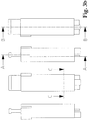
- Fig. 3a and Fig. 3b show different views of the interchangeable inhaler component 2.
- the Fig. 4-9 provide further information about the internal structure of the inhaler component 2.
- the housing 3 of the inhaler component 2 has a substantially cuboid shape.
- the essential components for the formation of the vapor-air mixture or / and Kondensationsaerosols include in particular the composites 10, which cause the evaporation of the liquid material.
- six composites 10 are arranged side by side, and the composites have a planar shape.
- the laminar composites 10 each consist of a wick and an electric heating element, which are connected to one another in a planar manner or integrated into one another in a planar manner.
- the laminar composites 10 may be formed, for example, by a metal foil and metal fabric layers sintered thereon. Instead of the metal fabric and open-cell metal foams can be used.
- the open-pored capillary structure of the fabric layers sintered onto the metal foil or the metal foam forms the wick, and the electrical resistance of the metal forms the heating element.
- Suitable metallic resistance materials are, for example, stainless steels such as AISI 304 or AISI 316 as well as heating conductor alloys, in particular NiCr alloys.
- the production of such laminar composites 10 belongs to the prior art and is for example in the already cited WO 2010/045671 (Helmut Buchberger) revealed in detail.
- Fig. 4b and Fig. 7 Best show the laminates 10 store with two end portions 10a, 10b on a support plate 11.
- the support plate 11 has a large recess 12, which is spanned by the bonds 10 without contact.
- the support plate 11 is designed in the concrete embodiment as a printed circuit board, in particular as a multilayer printed circuit board.
- As a material for the circuit board 11 are basically all known PCB materials, in particular the material types FR1 to FR5.
- the laminar composites 10 are electrically contacted in the region of the end sections 10a, 10b on printed conductors 13 of the printed circuit board 11. In Fig. 7 the tracks 13 are shown as black areas.
- the electrical contacting is preferably carried out by a foil-side soldering, optionally after pretreatment with a suitable flux.
- Stainless steels of the material qualities AISI 304 and AISI 316 can be soldered without problems, for example, using a soldering concentrate with the trade name "5050S-Nirosta" from Stannol GmbH, www.stannol.de.
- the electrical contacting may alternatively consist of an adhesive bond by means of an electrically conductive adhesive, for example by means of a silver-based epoxy-based adhesive.
- the assembly of the circuit board 11 with the laminar composites 10 and their contacting are fully automatic, with methods of the printed circuit board industry can be applied, which methods are otherwise suitable for mass production.
- the circuit board 11 projects out of the housing 3 in the form of the previously mentioned tabs 8a.
- the two tabs 8a serve to introduce the electrical energy into the inhaler component 2.
- the electrical energy is supplied to the composites 10 via the conductor tracks 13.
- the printed conductors 13 are arranged both on the front side 11a and on the rear side 11b of the printed circuit board 11, the front side 11a being the component side - this is the side on which the composites 10 are contacted.
- Further Conductor tracks can optionally also be arranged in intermediate layers.
- the individual interconnect layers are suitably connected to one another according to the prior art by means of so-called plated-through holes.
- Fig. 7 Furthermore, the current flow is shown. Accordingly, three composites 10 are connected in series in the concrete example in each case.
- the individual electrical resistances of the six composites 10 are of different sizes, for example by the thickness of the metal foil being varied accordingly. By this measure, the evaporation process similar to a cigarette can also be made dependent on the location.
- a substantially plate-shaped, preferably made of plastic upper part 14 is placed (see Fig. 4c and Fig. 8-10 ).
- the upper part 14 has a recess 15, which correlates with respect to their size and arrangement with the recess 12 in the printed circuit board 11.
- the upper part 14 rests directly on the end sections 10a, 10b of the laminations 10.
- the upper part 14 together with the printed circuit board 11 forms a capillary gap 16 whose inside width or gap width essentially corresponds to the thickness of the laminar laminates 10 (see FIG Fig. 9 and Fig. 10 ).
- the gap width is typically 0.2mm.
- Fig. 4d the areal extent of the capillary gap 16 is shown as a black area.
- the upper part 14 is fixed on the printed circuit board 11 by an adhesive connection, via two projections 14a, 14b and via a bracket 17.
- the printed circuit board 11 is mounted with its rear side 11b on a liquid container 19 containing the liquid material 18 (see FIG Fig. 4a / 4b . Fig. 8 and Fig. 10 ).
- the liquid container 19 or its wall is formed by the housing 3 and has a cuboid shape.
- the printed circuit board 11 is preferably fixed by means of an adhesive bond on the liquid container wall.
- the filling of the liquid container 19 with the liquid material 18 takes place at the factory at the end of the manufacturing process preferably via a small hole in the container wall (not shown) fully automatically by means of a cannula and a metering unit. The hole is closed after filling, for example sealed, and the whole inhaler component 2 is packaged airtight.
- the liquid container 19 has at its lower end two closely juxtaposed openings - the supply port 20 and the vent opening 21 (see Fig. 5 . Fig. 6 and Fig. 9 ).
- the supply opening 20 corresponds to a passage opening 22, which is formed by the edge of the circuit board 11 and an extension 23 of the liquid container wall (see Fig. 6 and Fig. 9 ).
- the extension 23 simultaneously forms a stop for the upper part 14.
- the extension 23 is supported via a web 24 on the housing 3.
- the supply of the capillary gap 16 with the liquid material 18 via the supply port 20 and the passage opening 22 and is driven by the capillary acting in the capillary 16 capillary forces.
- liquid material 18 In order for these capillary forces to act at all, it is necessary for the liquid material 18 to thoroughly wet all exposed surfaces. To ensure this, the affected components - these are the liquid container 19, the printed circuit board 11 together with composites 10 and the upper part 14 - to hydrophilize prior to assembly in a suitable process.
- Suitable processes are the hydrophilization in the oxygen plasma and the hydrophilization by means of plasma polymerization. Both processes, for example, by the company Diener electronic GmbH u. Co. KG, www.plasma.de, offered as part of contract work. The said company is also able to custom design and build appropriate, suitable for mass production facilities.
- the ventilation opening 21 corresponds to a ventilation groove 25 introduced into the printed circuit board 11, which in turn communicates via the recess 12 with an interior space which is at atmospheric pressure.
- the ventilation opening 21 and the ventilation groove 25 cause a pressure equalization, by replacing each portion of liquid material 18 which enters the capillary gap 16 with an equal volume of air.
- the sponges 27a, 27b receive condensate deposits formed in their pores from the vapor phase and prevent the inhalator component 2 from forming freely mobile condensate deposits which could impair the function of the inhaler component. Such condensate accumulations can also pose a problem from a hygienic point of view, in particular if they reach the oral cavity of a user via the mouthpiece 4.
- the sponges 27a, 27b preferably consist of a fine-pored fiber composite. Filtrona Fibertec GmbH, www.filtronafibertec.com, specializes in the production of such fiber composites using both triacetin-bound cellulose acetate fibers and thermally bonded polyolefin and polyester fibers.
- the sponges 27a, 27b bear on angle profiles 29a, 29b formed by a U-shaped support 29 (see FIG Fig. 4e and Fig. 10 ).
- the carrier 29 is joined to the upper part 14 by an adhesive connection.
- the carrier 29 together with angle sections 29a, 29b is preferably made of a hydrophobic plastic.
- the hydrophobic material acts as a liquid barrier and ensures that no liquid material 18 can reach the sponges 27a, 27b by capillary action.
- the angle sections 29a, 29b connecting leg 29c is on the upper part 14 side facing a recess 30 incorporated, which forms an air nozzle 31 together with the upper part 14 (see Fig. 9 and Fig. 10 ).
- the air nozzle 31 is, as will be shown in more detail later, the introduction of ambient air into the chamber 28. So that condensate deposits do not block the air nozzle 31, it is advisable to cover the Oberf kaue of the upper part 14 in the air nozzle 31 with a thin hydrophobic tape (not shown).
- the inhaler component 2 is supplied with ambient air to form the vapor / air mixture or / and condensation aerosol via a suction snorkel 32 formed by the housing 3 (see FIG Fig. 3a / 3b and Figure 8 ).
- the suction snorkel 32 is arranged on the side of the inhaler component 2 opposite the mouthpiece 4. This situation protects most from the Entry of rainwater.
- the suction snorkel 32 of the inhaler component 2 projects through a hole 33 formed through the main housing 5 of the inhaler part 1 (see FIG Fig. 2 ).
- In the intake snorkel 32 is a flow restrictor 34.
- the flow restrictor 34 has the purpose of creating a flow resistance which is similar to that of a cigarette, so that the user during a train feels a similar draw resistance as in a train on a cigarette. Specifically, the flow resistance should be at a flow rate of 1.05 L / min in the range 8-16 mbar and have a linear characteristic as possible.
- the flow restrictor 34 is required if the vapor-air mixture or / and condensation aerosol formed is to be supplied as in the case of a cigarette, namely as a pull into the oral cavity (tensile volume: approx. 20-80mL), optionally followed by inhalation into the lung , This mode of operation is recommended especially when the liquid material contains 18 nicotine.
- the flow restrictor 34 is eliminated if the inhaler is to permit direct pulmonary inhalation in a single step, as is the case with most medical inhalers.
- the flow restrictor 34 preferably consists of a cigarette filter-like fiber composite, wherein the density of the material is to be matched to the aforementioned flow characteristics.
- the material can in turn be obtained from Filtrona Fibertec GmbH, www.filtronafibertec.com.
- a user couples a new inhaler component 2 with the reusable inhaler part 1.
- the electrical circuit 7 registers the coupling and, if necessary, initiates certain preparatory operations, for example one or more evaporation cycles with the aim of to provide the composites 10 with fresh liquid material 18 and / or to produce stationary conditions. Once these operations are completed, the electrical circuit 7 signals, for example via a light emitting diode, the operational readiness of the inhaler.
- the user applies the mouthpiece 4 of the inhaler to the mouth and operates the switch 7a. At the same time he begins to pull the mouthpiece 4.
- the result generated negative pressure causes air from the environment flows into the intake snorkel 32.
- the flow bends at right angles (see arrows in Fig. 8 and Fig. 9 ) and opens into a plenum chamber 35, where the air collects and then evenly the slot-shaped air nozzle 31 is supplied.
- the air flow is accelerated in the air nozzle 31 and enters the chamber 28 at a high muzzle velocity.
- Actuation of the switch 7a causes the circuit 7 to turn on the heating current.
- the heating current is preferably switched by means of power MOSFET, wherein the supplied power can be adapted by a duty cycle (duty cycle) to the respective requirements. Within certain limits, this adaptation can also be carried out by the user via an interface, which makes it possible for him to influence the quantity of aerosol or smoke produced.
- the heating current is switched for a preset time period ("heating period"), which is typically 1.0-1.8 seconds.
- the heating current is supplied to the composites 10 via the tabs 8a and the printed conductors 13 of the printed circuit board 11 and causes a flash-like heating of the composites 10 and stored in the wicks liquid material 18, whereupon the liquid material 18 evaporates.
- the vapor is emitted into the chamber 28, where it mixes with the air flowing through the air nozzle 31.
- the arrangement and dimensioning of the air nozzle 31 causes a uniform and rapid flow over the composites 10. This ensures that the liberated from the composites 10 steam on all sides finds approximately the same mixing conditions, and the mixture of steam and air is intimately.
- the air causes cooling of the vapor, so that in addition a condensation aerosol can form, provided that the vaporized liquid material contains 18 substances with sufficiently low vapor pressure - so-called aerosol forming substances.
- a typical example of such aerosol forming substances is glycerol.
- the vapor-air mixture or / and condensation aerosol formed in the chamber 28 flows through one more time Cooler 36 before it is presented to the user via the mouthpiece 4 for inhalation (see Fig. 4e and Fig. 8 ).
- the cooler 36 may for example consist of a porous filling material, a non-woven fiber material or an open-cell foam material whose pores are flowed through by the formed vapor-air mixture or / and condensation aerosol.
- the cooler 36 may also be designed in several stages, with the individual cooler stages having different properties. If the material to be evaporated contains nicotine, it may be advantageous to coat the cooler material of at least one cooler stage with a suitable absorbent, for example with citric acid. The absorbent extracts from the flowing condensation aerosol highly volatile nicotine fractions, which would otherwise be deposited in the oral cavity and throat, which is neither pharmacokinetic nor organoleptically desirable. Flavoring agents such as menthol may also be added to the cooler material.
- Suitable non-woven fiber materials can be obtained, for example, from Freudenberg Nonwovens KG, www.freudenberg-filter.com.
- the material sold under the name Viledon® filter mats and consisting of polyolefin fibers is made to customer specification, wherein the material properties can be adjusted so that the end product for the fine particles of the condensation aerosol produced is largely permeable.
- a suitable foam material may be obtained, for example, from Dunlop Equipment, www.dunlop-equipment.com.
- the cited supplier offers Ni and NiCr foam under the product name Retimet® (Grade 80) with a porosity of 90-95% and a pore diameter of about 300 ⁇ m in sheet form up to thicknesses of 15mm.
- Ni foam and in particular NiCr foam are characterized by a high strength and by a high temperature and oxidation resistance. These characteristics suggest the comparatively expensive ones Metal foams at the end of the life of the Inhalatorkomponente 2 to recycle and reuse. If the liquid material contains 18 nicotine, the inhaler component 2 should in principle only be dispensed to the consumer against an adequate deposit. In this way it is ensured that the majority of contaminated with nicotine residues cooler 36, sponges 27a, 27b and liquid container 19 disposed of environmentally friendly and optionally recycled.
- the circuit 7 deactivates the switch 7a for a few seconds.
- the deactivation is indicated to the user by, for example, a light emitting diode and is required for the composites 10 to cool and for the wicks to re-soak with the liquid material 18.
- the liquid transport is originally induced by the capillarity of the composites 10 or their wicks.
- the wicks suck the liquid material 18 over the composite end portions 10a, 10b out of the capillary gap branches 16a, 16b (see FIG Fig. 4b and Fig. 10 ).
- the wicks are thus infiltrated from two sides.
- a nicotine-containing preparation of the liquid material 18 is disclosed, which was evaporated in prototypes (see Table 1).
- the condensation aerosol formed and administered in this case came with regard to the pharmacological, pharmacokinetic and organoleptic Effects very close to the smoke of a conventional cigarette. All listed ingredients are also found in cigarette smoke.
- the invention is of course not limited to one or more laminates 10 according to the embodiment just described.
- the composites 10 may also be formed linear or thread-like.
- the composites do not necessarily have to be even or straight, but rather can have any desired shape.
- the composites can also be electrically interconnected in any way.
- the invention also includes devices in which the liquid container 19 is arranged separable from the housing 3, so that the liquid container 19, as soon as it is empty, can be replaced by a new liquid container.
Description
Die Erfindung betrifft eine Inhalatorkomponente für die Bildung eines Dampf-Luft-Gemisches oder/und Kondensationsaerosols durch Verdampfung eines flüssigen Materials und gegebenenfalls Kondensation des gebildeten Dampfes, umfassend:
- ein elektrisches Heizelement zur Verdampfung einer Portion des flüssigen Materials;
- einen Docht mit einer Kapillarstruktur, welcher Docht mit dem Heizelement einen Verbund bildet und das Heizelement selbsttätig mit dem flüssigen Material versorgt;
- eine Trägerplatte, vorzugsweise Leiterplatte, welche den Verbund trägt und auf welcher das Heizelement elektrisch kontaktiert ist;
- einen zumindest zum Teil durch die Trägerplatte gebildeten Kapillarspalt zur selbsttätigen Versorgung des Verbundes mit dem flüssigen Material, indem ein Endabschnitt des Dochts in den Kapillarspalt ragt;
- einen das flüssige Material enthaltenden Flüssigkeitsbehälter, von welchem der Kapillarspalt das flüssige Material bezieht.
- an electric heating element for evaporating a portion of the liquid material;
- a wick having a capillary structure which wick forms a composite with the heating element and automatically supplies the heating element with the liquid material;
- a support plate, preferably printed circuit board, which carries the composite and on which the heating element is electrically contacted;
- a capillary gap formed at least in part by the support plate for automatically supplying the composite with the liquid material by projecting an end portion of the wick into the capillary gap;
- a liquid container containing the liquid material, from which the capillary gap receives the liquid material.
In der gegenständlichen Patentanmeldung bezieht sich der Begriff "Inhalator" auf medizinische wie nicht-medizinische Inhalatoren. Der Begriff bezieht sich ferner auf Inhalatoren zur Verabreichung von Arzneimitteln und solchen Stoffen, welche nicht als Arzneimittel deklariert sind. Der Begriff bezieht sich außerdem auf Rauchartikel und Zigarettenersatz-Artikel, wie sie beispielsweise in der Europäische Patentklasse A24F47/00B enthalten sind, soweit diese dazu bestimmt sind, dem Benutzer ein Dampf-Luft-Gemisch oder/und Kondensationsaerosol darzureichen. Der Begriff "Inhalator" soll auch keine Einschränkungen dahingehend machen, wie das gebildete Dampf-Luft-Gemisch oder/und Kondensationsaerosol dem Benutzer bzw. dessen Körper zugeführt wird. Das Dampf-Luft-Gemisch oder/und Kondensationsaerosol kann in die Lunge inhaliert werden, oder aber auch nur der Mundhöhle zugeführt werden - ohne Inhalation in die Lunge.In the subject patent application, the term "inhaler" refers to both medical and non-medical inhalers. The term also refers to inhalers for the administration of medicaments and those substances that are not declared as medicines. The term also refers to smoking articles and cigarette replacement articles, such as those contained in European Patent A24F47 / 00B, insofar as these are intended to present to the user a vapor-air mixture and / or condensation aerosol. The term "inhaler" is not intended to make any restrictions on how the formed vapor-air mixture and / or condensation aerosol is supplied to the user or his body. The vapor-air mixture and / or condensation aerosol can be inhaled into the lungs, or even be delivered only to the oral cavity - without inhalation into the lungs.
Als "Kapillarspalt" gelte ein jeder Spalt, welcher allein aufgrund der Kapillarwirkung seiner Begrenzungswände einen Flüssigkeitstransport bewirkt. Dochte, ummantelte Dochte oder mit Dochtmaterial befüllte Kanäle sind keine Kapillarspalten.As a "capillary gap" applies any gap, which causes solely due to the capillary action of its boundary walls a liquid transport. Wicks, jacketed wicks or channels filled with wick material are not capillary columns.
Die Verwendung des Singulars "Verbund" schließt das Vorhandensein mehrerer Verbunde nicht aus. Die Erfindung schließt Anordungen mit mehreren Verbunden explizit ein.The use of the singular "composite" does not exclude the existence of several compounds. The invention explicitly includes multi-connection arrangements.
Der Flüssigkeitsbehälter 4 ist in der Ansicht nach
Der Erfindung liegt die Aufgabe zugrunde, die zuvor aufgezeigten Nachteile der aus dem Stand der Technik bekannten Anordnung zu beheben. Der Erfindung liegt insbesondere die Aufgabe zugrunde, eine Inhalatorkomponente der eingangs geschilderten Art so auszugestalten, daß eine vergleichsweise kompakte Gesamtanordnung mit einem entsprechend kleinen Bauvolumen erzielt werden kann. Ferner sollen auch Kapillarspalten mit einer größeren flächigen Ausdehnung vorgesehen werden können.The invention has for its object to overcome the above-mentioned disadvantages of the known from the prior art arrangement. The invention is in particular the object of an inhaler component of the type described in such a way that a relatively compact overall arrangement can be achieved with a correspondingly small volume. Furthermore, capillary gaps with a larger areal extent should also be able to be provided.
Die Aufgabe wird durch die kennzeichnenden Merkmale des Aspeketes 1 gelöst. Demnach ist vorgesehen, daß der Kapillarspalt den Flüssigkeitsbehälter in einer Ansicht senkrecht zur Trägerplatte außen zumindest teilweise überdeckt. Im Sinne der vorliegenden Erfindung gelte auch als "überdeckend", wenn zwischen dem Kapillarspalt und dem Flüssigkeitsbehälter noch weitere Bauteile angeordnet sind. Bedenkt man, daß die den Kapillarspalt bildenden Komponenten senkrecht zur Trägerplatte nur wenig Raum fordern, wird verständlich, daß durch die erfindungsgemäße Anordung Bauraum eingespart werden kann.The object is achieved by the characterizing features of Aspeketes 1. Accordingly, it is provided that the capillary gap at least partially covers the liquid container in a view perpendicular to the carrier plate. For the purposes of the present invention, the term "overlapping" also applies if further components are arranged between the capillary gap and the liquid container. Considering that the components forming the capillary gap require only little space perpendicular to the carrier plate, it is understood that space can be saved by the arrangement according to the invention.
In einer Weiterbildung der Erfindung ist vorgesehen, daß der Verbund den Flüssigkeitsbehälter in einer Ansicht senkrecht zur Trägerplatte zumindest teilweise überdeckt. Im Sinne der vorliegenden Erfindung gelte auch als "überdeckend", wenn zwischen dem Verbund und dem Flüssigkeitsbehälter noch weitere Bauteile angeordnet sind. Beachtet man, daß es sich beim Verbund in der Regel um ein relativ dünnes Gebilde handelt, leuchtet ein, daß durch diese weitere Überdeckung nochmals Bauraum eingespart werden kann.In a further development of the invention it is provided that the composite at least partially covers the liquid container in a view perpendicular to the support plate. For the purposes of the present invention, the term "overlapping" also applies if further components are arranged between the composite and the liquid container. If one observes that the composite is generally a relatively thin structure, it is clear that further space can be used to save space again.
In einer bevorzugten Ausbildung der Erfindung ist vorgesehen, daß die Trägerplatte zumindest abschnittsweise auf dem Flüssigkeitsbehälter lagert. Der Flüssigkeitsbehälter und die Trägerplatte sind also übereinander gestapelt angeordnet. Konstruktiv besonders vorteilhaft ist es, wenn der Flüssigkeitsbehälter im Wesentlichen die Form eines Quaders hat, und die Trägerplatte zumindest abschnittsweise auf einer Seitenfläche des Quaders lagert. Hierdurch kann der zur Verfügung stehende Bauraum in optimaler Weise genutzt werden. Die Trägerplatte besteht vorzugsweise aus einer Leiterplatte, insbesondere aus einer mehrlagigen sogenannten Multilayer-Leiterplatte. Die den elektrischen Heizstrom zu- bzw. abführenden Leiterbahnen können dadurch nämlich auf mehrere Lagen aufgeteilt werden, so daß auch sehr hohe Heizströme weitgehend verlustfrei transportiert werden können.In a preferred embodiment of the invention it is provided that the carrier plate at least partially superimposed on the liquid container. The liquid container and the carrier plate are thus stacked one above the other. It is particularly advantageous in terms of construction if the liquid container has substantially the shape of a cuboid, and supports the carrier plate at least in sections on a side surface of the cuboid. As a result, the available space can be used in an optimal way. The carrier plate preferably consists of a printed circuit board, in particular of a multilayer so-called multilayer printed circuit board. The the electrical heating current to or dissipating interconnects can thus be divided into several layers, so that even very high heating currents can be transported largely lossless.
Die Erfindung betrifft außerdem einen Inhalator, umfassend eine erfindungsgemäße Inhalatorkomponente wie zuvor beschrieben. Die Inhalatorkomponente kann also auch nur ein Teil, insbesondere ein auswechselbares Teil eines Inhalators sein.The invention also relates to an inhaler comprising an inhaler component according to the invention as described above. The inhaler component can thus also be only a part, in particular a replaceable part of an inhaler.
Die Erfindung wird anhand eines Ausführungsbeispiels gemäß den Zeichnungen näher erläutert.The invention will be explained in more detail with reference to an embodiment according to the drawings.
Es zeigen:
-
Fig. 1 einen erfindungsgemäßen Inhalator in verschiedenen Ansichten; -
Fig. 2 den Inhalator nachFig. 1 mit einem wiederverwendbaren Inhalatorteil und einer auswechselbaren Inhalatorkomponente im entkoppelten Zustand; -
Fig. 3a undFig 3b die auswechselbare Inhalatorkomponente in verschiedenen Ansichten; -
Fig. 4a ,Fig. 4b ,Fig. 4c ,Fig. 4d undFig. 4e Schnittansichten der auswechselbaren Inhalatorkomponente längs der Linie A-A inFig. 3b in verschiedenen Montagezuständen; -
Fig. 5 das Detail a ausFig. 4a in einer vergrößerten Darstellung; -
Fig. 6 das Detail b ausFig. 4b in einer vergrößerten Darstellung; -
Fig. 7 eine als Multilayer-Leiterplatte ausgeführte Trägerplatte; -
Fig. 8 eine Schnittansicht der auswechselbaren Inhalatorkomponente längs der Linie B-B inFig. 3b ; -
Fig. 9 das Detail c ausFig. 8 in einer vergrößerten Darstellung; -
Fig. 10 eine Schnittansicht der auswechselbaren Inhalatorkomponente in Höhe der Verbunde längs der Linie C-C inFig. 3b .
-
Fig. 1 an inhaler according to the invention in different views; -
Fig. 2 the inhalerFig. 1 with a reusable inhaler part and a replaceable inhaler component in the decoupled state; -
Fig. 3a andFig. 3b the replaceable inhaler component in different views; -
Fig. 4a .Fig. 4b .Fig. 4c .Fig. 4d andFig. 4e Sectional views of the interchangeable inhaler component along the line AA in FIGFig. 3b in different assembly states; -
Fig. 5 the detail a offFig. 4a in an enlarged view; -
Fig. 6 the detail b offFig. 4b in an enlarged view; -
Fig. 7 a designed as a multilayer printed circuit board carrier plate; -
Fig. 8 a sectional view of the interchangeable Inhalatorkomponente along the line BB inFig. 3b ; -
Fig. 9 the detail c offFig. 8 in an enlarged view; -
Fig. 10 a sectional view of the interchangeable Inhalatorkomponente at the level of the composites along the line CC inFig. 3b ,
Die Inhalatorkomponente 2 besteht aus einem Gehäuse 3, welches an einer Stirnseite ein tabakpfeifenartiges Mundstück 4 ausbildet. Das Gehäuse 3 ist vorzugsweise aus Kunststoff gefertigt. Die Inhalatorkomponente 2 beinhaltet ein flüssiges Material, welches innerhalb des Gehäuses 3 elektrisch verdampft wird und in ein inhalierbares Dampf-Luft-Gemisch oder/und Kondensationsaerosol übergeführt wird. Das gebildete Dampf-Luft-Gemisch oder/und Kondensationsaerosol wird dem Benutzer über das Mundstück 4 dargeboten. Als flüssiges Material kommen grundsätzlich alle Stoffe und Zubereitungen in Betracht, welche unter atmosphärischen Bedingungen weitgehend rückstandsfrei verdampfen. Diese Bedingung ist auch schon erfüllt, wenn der jeweilige Stoff oder die jeweilige Zubereitung verdünnt, beispielsweise in Wasser oder/ und Ethanol gelöst vorliegt und die Lösung weitgehend rückstandsfrei verdampft. Durch eine hinreichend hohe Verdünnung in einem leicht flüchtigen Lösungsmittel wie Wasser oder/und Ethanol können auch sonst schwer verdampfbare Stoffe die zuvor genannte Bedingung erfüllen, und eine thermische Zersetzung des flüssigen Materials vermieden oder deutlich verringert werden. Die durch Kondensation erzeugten Aerosolteilchen weisen in der Regel einen massemedianen aerodynamischen Durchmesser (MMAD) kleiner als 2µm auf und erreichen dadurch auch die Alveolen. Der erfindungsgemäße Inhalator eignet sich insbesondere für die Verabreichung von systemisch wirkenden Stoffen - insbesondere solchen Wirkstoffen, welche ihre Hauptwirkung im zentralen Nervensystem entfalten. Als Beispiel sei Nikotin erwähnt, dessen Siedepunkt bei 246°C liegt. Die nikotinhaltigen Aerosolpartikel werden vorwiegend in den Bronchien und Alveolen niedergeschlagen, wo der Wirkstoff blitzartig in den Blutkreislauf übergeht. Wenige Sekunden später erreicht das Nikotin in gebündelter Konzentration das Gehirn und kann dort die bekannten Wirkungen entfalten.The
Das Inhalatorteil 1 besteht aus einem Hauptgehäuse 5, welches vorzugsweise wieder aus Kunststoff gefertigt ist. Das Hauptgehäuse 5 beinhaltet zumindest eine Batterie 6 und einen elektrischen Schaltkreis 7 (in
Wie die
Die mechanische Kopplung zwischen der auswechselbaren Inhalatorkomponente 2 und dem wiederverwendbaren Inhalatorteil 1 erfolgt über Steckzungen 8a und durch das Gehäuse 3 gebildete Führungsnasen 9a, welche in korrespondierende, durch das Hauptgehäuse 5 des wiederverwendbaren Inhalatorteils 1 gebildete Steckbuchsen 8b und Führungsnuten 9b eingreifen. Die Steckzungen 8a und Steckbuchsen 8b dienen gleichzeitig zur Einleitung der elektrischen Energie in die auswechselbare Inhalatorkomponente 2 zur Verdampfung des flüssigen Materials, wie nachfolgend noch detaillierter gezeigt wird.The mechanical coupling between the
Wie
Die Leiterplatte 11 ragt aus dem Gehäuse 3 in Form der bereits früher erwähnten Steckzungen 8a heraus. Die beiden Steckzungen 8a dienen zur Einleitung der elektrischen Energie in die Inhalatorkomponente 2. Die elektrische Energie wird den Verbunden 10 über die Leiterbahnen 13 zugeführt. Nach
Auf die Vorderseite 11a der Leiterplatte 11 ist ein im Wesentlichen plattenförmiges, vorzugsweise aus Kunststoff bestehendes Oberteil 14 aufgesetzt (siehe
Die Leiterplatte 11 lagert mit ihrer Rückseite 11b auf einem das flüssige Material 18 enthaltenden Flüssigkeitsbehälter 19 (siehe
Der Flüssigkeitsbehälter 19 weist an seinem unteren Ende zwei eng nebeneinander angeordnete Öffnungen auf - die Versorgungsöffnung 20 und die Belüftungsöffnung 21 (siehe
Die Belüftungsöffnung 21 korrespondiert mit einer in die Leiterplatte 11 eingebrachten Belüftungsnut 25, welche ihrerseits über die Ausnehmung 12 mit einem unter Atmosphärendruck stehenden Innenraum kommuniziert. Die Belüftungsöffnung 21 und die Belüftungsnut 25 bewirken einen Druckausgleich, indem jede Portion flüssigen Materials 18, welche in den Kapillarspalt 16 gelangt, unmittelbar durch eine volumengleiche Portion Luft ersetzt wird.The
Die überlappende Anordnung der Leiterplatte 11 und des Flüssigkeitsbehälters 19, sowie die zuvor beschriebene Anordnung der Versorgungsöffnung 20, der Durchtrittsöffnung 22 und der Belüftungsöffnung 21 gestatten es, eine vergleichsweise große Kapillarspaltfläche vorzusehen, welche erforderlich ist, wenn mehrere nebeneinander angeordnete Verbunde 10 mit dem flüssigen Material 18 zu versorgen sind. Die Gefahr, daß an irgendeiner Stelle durch das Wirken der Gravitation flüssiges Material 18 austritt, kann weitestgehend abgewendet werden. In der in
Bevor auf die Funktionsweise des erfindungsgemäßen Inhalators näher eingegangen wird, sollen im Folgenden noch weitere Bestandteile der Inhalatorkomponente 2 beschrieben werden. Auch wenn diese Bestandteile nicht unmittelbar erfindungsrelevant sein mögen, so trägt die Beschreibung derselben doch dazu bei, die Funktion der erfindungsgemäßen Inhalatorkomponente im Ganzen noch besser zu verstehen, und die Ausführbarkeit der Erfindung noch sicherer zu gewährleisten: zwischen dem Oberteil 14 und dem Gehäuse 3 sind zwei offenporige, saugfähige Schwämme 27a, 27b (siehe
Die Schwämme 27a, 27b lagern auf von einem U-förmigen Träger 29 gebildeten Winkelprofilen 29a, 29b (siehe
Die Versorgung der Inhalatorkomponente 2 mit Umgebungsluft zur Bildung des Dampf-Luft-Gemisches oder/und Kondensationsaerosols erfolgt über einen durch das Gehäuse 3 gebildeten Ansaugschnorchel 32 (siehe
Im Folgenden soll die Funktion des Inhalators im Detail beschrieben werden: ein Benutzer koppelt eine neue Inhalatorkomponente 2 mit dem wiederverwendbaren Inhalatorteil 1. Der elektrische Schaltkreis 7 registriert die Kopplung und veranlaßt gegebenenfalls die Ausführung bestimmter vorbereitender Operationen, beispielsweise eines oder mehrerer Verdampfungszyklen mit dem Ziel, die Verbunde 10 mit frischem flüssigen Material 18 zu versorgen oder/und stationäre Bedingungen herzustellen. Sobald diese Operationen abgeschlossen sind, signalisiert der elektrische Schaltkreis 7 zum Beispiel über eine Leuchtdiode die Betriebsbereitschaft des Inhalators. Der Benutzer führt das Mundstück 4 des Inhalators an den Mund und betätigt den Schalter 7a. Gleichzeitig beginnt er am Mundstück 4 zu ziehen. Der hierdurch erzeugte Unterdruck bewirkt, daß Luft aus der Umgebung in den Ansaugschnorchel 32 strömt. Nachdem die Luft die Strömungsdrossel 34 durchsetzt hat, biegt die Strömung im rechten Winkel ab (siehe Pfeile in
Die Betätigung des Schalters 7a bewirkt, daß der Schaltkreis 7 den Heizstrom einschaltet. Der Heizstrom wird vorzugsweise mittels Leistungs-MOSFET geschaltet, wobei die zugeführte Leistung durch eine Taktung (Duty Cycle) den jeweiligen Erfordernissen angepaßt werden kann. Diese Anpassung kann in bestimmten Grenzen auch durch den Benutzer über eine Schnittstelle erfolgen, wodurch es diesem ermöglicht wird, auf die erzeugte Aerosol- bzw. Rauchmenge Einfluß zu nehmen. Der Heizstrom wird für eine voreingestellte Zeitperiode ("Heizperiode") geschaltet, welche typischerweise 1,0-1,8 Sekunden beträgt. Der Heizstrom wird den Verbunden 10 über die Steckzungen 8a und die Leiterbahnen 13 der Leiterplatte 11 zugeführt und bewirkt eine blitzartige Aufheizung der Verbunde 10 und des in den Dochten gespeicherten flüssigen Materials 18, woraufhin das flüssige Material 18 verdampft. Der Dampf wird in die Kammer 28 emittiert, wo er sich mit der durch die Luftdüse 31 einströmenden Luft mischt. Die Anordnung und Dimensionierung der Luftdüse 31 bewirkt eine gleichmäßige und schnelle Überströmung der Verbunde 10. Hierdurch wird sichergestellt, daß der von den Verbunden 10 freigesetzte Dampf allseits annähernd gleiche Mischungsbedingungen vorfindet, und die Mischung von Dampf und Luft innig ist. Die Luft bewirkt eine Kühlung des Dampfes, so daß sich außerdem ein Kondensationsaerosol ausbilden kann, sofern das verdampfte flüssige Material 18 Substanzen mit hinreichend niedrigem Dampfdruck - sogenannte aerosolbildende Substanzen - enthält. Ein typisches Beispiel für solche aerosolbildenden Substanzen ist Glycerol.Actuation of the
Das in der Kammer 28 gebildete Dampf-Luft-Gemisch oder/und Kondensationsaerosol durchströmt schließlich im Ausführungsbeispiel noch einen Kühler 36, bevor es dem Benutzer über das Mundstück 4 zur Inhalation dargeboten wird (siehe
Geeignete vliesartige Fasermaterialien können beispielsweise von der Firma Freudenberg Vliesstoffe KG, www.freudenberg-filter.com, bezogen werden. Das unter der Bezeichnung Viledon®-Filtermatten vertriebene und aus Polyolefinfasern bestehende Material wird nach Kundenspezifikation angefertigt, wobei die Materialeigenschaften so abgestimmt werden können, daß das Endprodukt für die feinen Partikel des erzeugten Kondensationsaerosols weitestgehend durchlässig ist. Ein geeignetes Schaummaterial kann zum Beispiel von der Firma Dunlop Equipment, www.dunlop-equipment.com bezogen werden. Der angeführte Lieferant bietet Ni- und NiCr-Schaum unter der Produktbezeichnung Retimet® (Grade 80) mit einer Porosität von 90-95% und einem Porendurchmesser von etwa 300µm in Plattenform bis zu Dicken von 15mm an. Nach mündlicher Mitteilung von Firmenvertretern können aus technologischer Sicht auch noch etwas feinporigere Schäume hergestellt werden. Die Metallschäume können außerdem durch Walzen zusätzlich verdichtet werden. Die Platten können durch Laserschneiden oder Drahterodieren weiterverarbeitet werden. Ni-Schaum und insbesondere NiCr-Schaum zeichnen sich durch eine hohe Festigkeit sowie durch eine hohe Temperatur- und Oxidationsbeständigkeit aus. Diese Eigenschaften legen es nahe, die vergleichsweise teuren Metallschäume am Ende der Nutzungsdauer der Inhalatorkomponente 2 zu recyclen und wiederzuverwenden. Enthält das flüssige Material 18 Nikotin, sollte die Inhalatorkomponente 2 grundsätzlich nur gegen ein angemessenes Pfand an den Verbraucher abgegeben werden. Auf diese Weise wird sichergestellt, daß der Großteil der mit Nikotinrückständen kontaminierten Kühler 36, Schwämme 27a, 27b und Flüssigkeitsbehälter 19 umweltgerecht entsorgt und gegebenenfalls wiederaufbereitet wird.Suitable non-woven fiber materials can be obtained, for example, from Freudenberg Nonwovens KG, www.freudenberg-filter.com. The material sold under the name Viledon® filter mats and consisting of polyolefin fibers is made to customer specification, wherein the material properties can be adjusted so that the end product for the fine particles of the condensation aerosol produced is largely permeable. A suitable foam material may be obtained, for example, from Dunlop Equipment, www.dunlop-equipment.com. The cited supplier offers Ni and NiCr foam under the product name Retimet® (Grade 80) with a porosity of 90-95% and a pore diameter of about 300μm in sheet form up to thicknesses of 15mm. After verbal communication from company representatives, from a technological point of view, even finer-pore foams can be produced. The metal foams can also be densified by rolling. The plates can be further processed by laser cutting or wire EDM. Ni foam and in particular NiCr foam are characterized by a high strength and by a high temperature and oxidation resistance. These characteristics suggest the comparatively expensive ones Metal foams at the end of the life of the
Am Ende der Heizperiode deaktiviert der Schaltkreis 7 den Schalter 7a für ein paar Sekunden. Die Deaktivierung wird dem Benutzer zum Beispiel durch eine Leuchtdiode angezeigt und ist erforderlich, damit die Verbunde 10 abkühlen können, und die Dochte sich von neuem mit dem flüssigen Material 18 vollsaugen können. Der Flüssigkeitstransport wird ursprünglich durch die Kapillarität der Verbunde 10 bzw. deren Dochte induziert. Die Dochte saugen das flüssige Material 18 über die Verbund-Endabschnitte 10a, 10b aus den Kapillarspalt-Ästen 16a, 16b (siehe
Abschließend soll beispielhaft noch eine nikotinhaltige Zubereitung des flüssigen Materials 18 offenbart werden, welche in Prototypen verdampft wurde (siehe Tabelle 1). Das hierbei gebildete und verabreichte Kondensationsaerosol kam hinsichtlich der pharmakologischen, pharmakokinetischen sowie organoleptischen Wirkungen dem Rauch einer konventionellen Zigarette sehr nahe. Sämtliche aufgeführten Inhaltsstoffe finden sich auch im Zigarettenrauch wieder.
Es sei noch darauf hingewiesen, daß die Erfindung selbstverständlich nicht auf einen oder mehrere flächige Verbunde 10 gemäß dem soeben beschriebenen Ausführungsbeispiel beschränkt ist. Die Verbunde 10 können ebenso linien- bzw. fadenförmig ausgebildet sein. Die Verbunde müssen auch nicht zwingend eben bzw. geradlinig sein, sondern können vielmehr jede beliebige Gestalt aufweisen. Die Verbunde können ferner in beliebiger Weise miteinander elektrisch verschaltet sein. Schließlich umfaßt die Erfindung auch Vorrichtungen, in welchen der Flüssigkeitsbehälter 19 vom Gehäuse 3 trennbar angeordnet ist, so daß der Flüssigkeitsbehälter 19, sobald er leer ist, durch einen neuen Flüssigkeitsbehälter ersetzt werden kann.It should be noted that the invention is of course not limited to one or
Die Anmeldung umfasst insbesondere auch die folgenden Aspekte:
Aspekt 1. Inhalatorkomponente für die Bildung eines Dampf-Luft-Gemisches oder/und Kondensationsaerosols durch Verdampfung eines flüssigen Materials (18) und gegebenenfalls Kondensation des gebildeten Dampfes, umfassend:- ein elektrisches Heizelement zur Verdampfung einer Portion des flüssigen Materials (18);
- einen Docht mit einer Kapillarstruktur, welcher Docht mit dem Heizelement einen Verbund (10) bildet und das Heizelement selbsttätig mit dem flüssigen Material (18) versorgt;
- eine Trägerplatte (11), vorzugsweise Leiterplatte, welche den Verbund (10) trägt und auf welcher das Heizelement elektrisch kontaktiert ist;
- einen zumindest zum Teil durch die Trägerplatte (11) gebildeten Kapillarspalt (16) zur selbsttätigen Versorgung des Verbundes (10) mit dem flüssigen Material (18), indem ein Endabschnitt des Dochts in den Kapillarspalt (16) ragt;
- einen das flüssige Material (18) enthaltenden Flüssigkeitsbehälter (19), von welchem der Kapillarspalt (16) das flüssige Material (18) bezieht,
- dadurch gekennzeichnet, daß der Kapillarspalt (16) den Flüssigkeitsbehälter (19) in einer Ansicht senkrecht zur Trägerplatte (11) außen zumindest teilweise überdeckt.
Aspekt 2.Inhalatorkomponente nach Aspekt 1, dadurch gekennzeichnet, daß der Verbund (10) den Flüssigkeitsbehälter (19) in einer Ansicht senkrecht zur Trägerplatte (11) zumindest teilweise überdeckt.Aspekt 3.Inhalatorkomponente nach Aspekt 1oder 2, dadurch gekennzeichnet, daß die Trägerplatte (11) zumindest abschnittsweise auf dem Flüssigkeitsbehälter (19) lagert.Aspekt 4.Inhalatorkomponente nach Aspekt 3, dadurch gekennzeichnet, daß der Flüssigkeitsbehälter (19) im Wesentlichen die Form eines Quaders hat, und die Trägerplatte (11) zumindest abschnittsweise auf einer Seitenfläche des Quaders lagert.Aspekt 5. Inhalator, umfassend eine Inhalatorkomponente (2) nach einem der Aspekte 1-4.
-
Aspect 1. An inhalant component for the formation of a vapor-air mixture or / and condensation aerosol by evaporation of a liquid material (18) and optionally condensation of the formed vapor, comprising:- an electric heating element for evaporating a portion of the liquid material (18);
- a wick having a capillary structure which wick forms a composite (10) with the heating element and automatically supplies the heating element with the liquid material (18);
- a support plate (11), preferably a printed circuit board, which carries the composite (10) and on which the heating element is electrically contacted;
- a capillary gap (16) formed at least in part by the support plate (11) for automatically supplying the composite (10) with the liquid material (18) by projecting an end portion of the wick into the capillary gap (16);
- a liquid container (19) containing the liquid material (18), from which the capillary gap (16) receives the liquid material (18),
- characterized in that the capillary gap (16) the liquid container (19) in a view perpendicular to the support plate (11) outside at least partially covered.
-
Aspect 2. Inhaler component according toaspect 1, characterized in that the composite (10) at least partially covers the liquid container (19) in a view perpendicular to the carrier plate (11). -
Aspect 3. Inhaler component according toaspect -
Aspect 4. Inhaler component according toaspect 3, characterized in that the liquid container (19) has substantially the shape of a cuboid, and the support plate (11) at least partially superimposed on a side surface of the cuboid. -
Aspect 5. An inhaler comprising an inhalant component (2) according to any one of aspects 1-4.
- 11
- wiederverwendbares Inhalatorteilreusable inhaler part
- 22
- auswechselbare Inhalatorkomponenteexchangeable inhaler component
- 33
- Gehäusecasing
- 44
- Mundstückmouthpiece
- 55
- Hauptgehäusemain body
- 66
- Batteriebattery
- 77
- elektrischer Schaltkreiselectrical circuit
- 7a7a
- Schalterswitch
- 8a8a
- Steckzungentabs
- 8b8b
- Steckbuchsensockets
- 9a9a
- Führungsnasenguide tabs
- 9b9b
- Führungsnutenguide
- 1010
- flächige Verbundeplanar composites
- 10a, 10b10a, 10b
- Verbund-EndabschnitteComposite end
- 1111
- Trägerplatte, Leiterplatte, Multilayer-LeiterplatteCarrier plate, printed circuit board, multilayer printed circuit board
- 11a11a
- Leiterplatten-VorderseitePCB Front
- 11b11b
- Leiterplatten-RückseitePCB back
- 1212
- Ausnehmungrecess
- 1313
- Leiterbahnenconductor tracks
- 1414
- Oberteiltop
- 14a, 14b14a, 14b
- Vorsprüngeprojections
- 1515
- Aussparungrecess
- 1616
- Kapillarspaltcapillary
- 16a, 16b16a, 16b
- Kapillarspalt-ÄsteCapillary gap branches
- 1717
- Haltewinkelbracket
- 1818
- flüssiges Materialliquid material
- 1919
- Flüssigkeitsbehälterliquid container
- 2020
- VersorgungsöffnungTreatment opening
- 2121
- Belüftungsöffnungventilation opening
- 2222
- DurchtrittsöffnungThrough opening
- 2323
- Fortsatzextension
- 2424
- Stegweb
- 2525
- Belüftungsnutvent groove
- 2626
- Luftvolumen, LuftpolsterAir volume, air cushion
- 27a, 27b27a, 27b
- offenporige, saugfähige Schwämmeporous, absorbent sponges
- 2828
- Kammerchamber
- 2929
- U-förmiger TrägerU-shaped carrier
- 29a, 29b29a, 29b
- Winkelprofileangle sections
- 29c29c
- Schenkelleg
- 3030
- Vertiefungdeepening
- 3131
- Luftdüseair nozzle
- 3232
- Ansaugschnorchelintake snorkel
- 3333
- Lochhole
- 3434
- Strömungsdrosselflow throttle
- 3535
- Plenumkammerplenum
- 3636
- Kühlercooler
Claims (7)
- Inhaler component for forming a vapour/air mixture or/and condensation aerosol by evaporation of a liquid material (18) and, if appropriate, condensation of the formed vapour, comprising:a) an electric heating element for evaporating a portion of the liquid material (18),b) a wick with a capillary structure, which wick forms a composite (10) with the heating element and supplies the heating element automatically with the liquid material (18),c) a carrier plate (11) which carries the composite (10),d) a capillary gap (16) formed at least partially by the carrier plate (11) and automatically supplying the composite (10) with the liquid material (18), by means of an end portion of the wick extending into the capillary gap (16), ande) a liquid container (19) which contains the liquid material (18) and from which the capillary gap (16) draws the liquid material (18),characterized in that the carrier plate (11) bears at least in part on the liquid container (19).
- Inhaler component according to Claim 1, characterized in that the capillary gap (16) at least partially covers the liquid container (19) on the outside, in a view perpendicular to the carrier plate (11).
- Inhaler component according to Claim 1, characterized in that the composite (10) at least partially covers the liquid container (19), in a view perpendicular to the carrier plate (11).
- Inhaler component according to Claim 3, characterized in that the liquid container (19) has substantially the shape of a cuboid, and the carrier plate (11) bears at least in part on a side surface of the cuboid.
- Inhaler component according to one of Claims 1 to 4, further comprising a substantially plate-shaped upper part (14) which has a recess (15) which, in terms of its size and arrangement, correlates with a recess (12) in the carrier plate (11).
- Inhaler component according to Claim 5, wherein the upper part (14) bears directly on the end portions (10a, 10b) of the composite (10).
- Inhaler, comprising an inhaler component (2) according to one of Claims 1 to 6.
Priority Applications (3)
| Application Number | Priority Date | Filing Date | Title |
|---|---|---|---|
| PL17197150T PL3305106T3 (en) | 2011-07-27 | 2012-07-24 | Inhaler component |
| EP17197150.0A EP3305106B1 (en) | 2011-07-27 | 2012-07-24 | Inhaler component |
| PL15178588T PL3023017T3 (en) | 2011-07-27 | 2012-07-24 | Inhaler component |
Applications Claiming Priority (2)
| Application Number | Priority Date | Filing Date | Title |
|---|---|---|---|
| ATA1095/2011A AT510837B1 (en) | 2011-07-27 | 2011-07-27 | INHALATORKOMPONENTE |
| EP12743375.3A EP2736360B1 (en) | 2011-07-27 | 2012-07-24 | Inhaler component |
Related Parent Applications (2)
| Application Number | Title | Priority Date | Filing Date |
|---|---|---|---|
| EP12743375.3A Division-Into EP2736360B1 (en) | 2011-07-27 | 2012-07-24 | Inhaler component |
| EP12743375.3A Division EP2736360B1 (en) | 2011-07-27 | 2012-07-24 | Inhaler component |
Related Child Applications (1)
| Application Number | Title | Priority Date | Filing Date |
|---|---|---|---|
| EP17197150.0A Division EP3305106B1 (en) | 2011-07-27 | 2012-07-24 | Inhaler component |
Publications (2)
| Publication Number | Publication Date |
|---|---|
| EP3023017A1 EP3023017A1 (en) | 2016-05-25 |
| EP3023017B1 true EP3023017B1 (en) | 2017-11-15 |
Family
ID=46614414
Family Applications (3)
| Application Number | Title | Priority Date | Filing Date |
|---|---|---|---|
| EP15178588.8A Active EP3023017B1 (en) | 2011-07-27 | 2012-07-24 | Inhaler component |
| EP17197150.0A Active EP3305106B1 (en) | 2011-07-27 | 2012-07-24 | Inhaler component |
| EP12743375.3A Active EP2736360B1 (en) | 2011-07-27 | 2012-07-24 | Inhaler component |
Family Applications After (2)
| Application Number | Title | Priority Date | Filing Date |
|---|---|---|---|
| EP17197150.0A Active EP3305106B1 (en) | 2011-07-27 | 2012-07-24 | Inhaler component |
| EP12743375.3A Active EP2736360B1 (en) | 2011-07-27 | 2012-07-24 | Inhaler component |
Country Status (12)
| Country | Link |
|---|---|
| US (2) | US9623205B2 (en) |
| EP (3) | EP3023017B1 (en) |
| JP (2) | JP5778867B2 (en) |
| CN (2) | CN105597203B (en) |
| AR (1) | AR087370A1 (en) |
| AT (1) | AT510837B1 (en) |
| ES (3) | ES2659787T3 (en) |
| HK (2) | HK1191522A1 (en) |
| HU (2) | HUE036026T2 (en) |
| PL (3) | PL3023017T3 (en) |
| TW (1) | TW201317014A (en) |
| WO (1) | WO2013013808A1 (en) |
Families Citing this family (135)
| Publication number | Priority date | Publication date | Assignee | Title |
|---|---|---|---|---|
| US20160345631A1 (en) | 2005-07-19 | 2016-12-01 | James Monsees | Portable devices for generating an inhalable vapor |
| AT507187B1 (en) | 2008-10-23 | 2010-03-15 | Helmut Dr Buchberger | INHALER |
| CA3114582A1 (en) | 2010-12-22 | 2012-06-28 | Syqe Medical Ltd. | Method and system for drug delivery |
| AT510837B1 (en) | 2011-07-27 | 2012-07-15 | Helmut Dr Buchberger | INHALATORKOMPONENTE |
| PL2672847T3 (en) | 2011-02-11 | 2015-10-30 | Batmark Ltd | Inhaler component |
| PT3811800T (en) | 2011-09-06 | 2023-04-28 | Nicoventures Trading Ltd | Heating smokable material |
| KR101953201B1 (en) | 2011-09-06 | 2019-02-28 | 브리티시 아메리칸 토바코 (인베스트먼츠) 리미티드 | Heating smokeable material |
| AT511344B1 (en) | 2011-10-21 | 2012-11-15 | Helmut Dr Buchberger | INHALATORKOMPONENTE |
| US20130255702A1 (en) | 2012-03-28 | 2013-10-03 | R.J. Reynolds Tobacco Company | Smoking article incorporating a conductive substrate |
| GB201207039D0 (en) | 2012-04-23 | 2012-06-06 | British American Tobacco Co | Heating smokeable material |
| GB2504076A (en) | 2012-07-16 | 2014-01-22 | Nicoventures Holdings Ltd | Electronic smoking device |
| GB2504075A (en) | 2012-07-16 | 2014-01-22 | Nicoventures Holdings Ltd | Electronic smoking device |
| US10279934B2 (en) | 2013-03-15 | 2019-05-07 | Juul Labs, Inc. | Fillable vaporizer cartridge and method of filling |
| US10638792B2 (en) | 2013-03-15 | 2020-05-05 | Juul Labs, Inc. | Securely attaching cartridges for vaporizer devices |
| GB2513639A (en) | 2013-05-02 | 2014-11-05 | Nicoventures Holdings Ltd | Electronic cigarette |
| GB2513638A (en) | 2013-05-02 | 2014-11-05 | Nicoventures Holdings Ltd | Electronic cigarette |
| GB2513637A (en) | 2013-05-02 | 2014-11-05 | Nicoventures Holdings Ltd | Electronic cigarette |
| CA3208137A1 (en) | 2013-05-06 | 2014-11-13 | Juul Labs, Inc. | Nicotine salt formulations for aerosol devices and methods thereof |
| GB2514893B (en) | 2013-06-04 | 2017-12-06 | Nicoventures Holdings Ltd | Container |
| EP3536179A1 (en) | 2013-08-06 | 2019-09-11 | Fontem Holdings 1 B.V. | Electronic smoking device and process of manufacturing thereof |
| AR097797A1 (en) * | 2013-09-26 | 2016-04-13 | Altria Client Services Inc | ELECTRONIC ITEM TO SMOKE |
| BE1022113B1 (en) * | 2013-11-08 | 2016-02-16 | Serenity Sa | ELECTRONIC CIGARETTE. |
| US10980273B2 (en) | 2013-11-12 | 2021-04-20 | VMR Products, LLC | Vaporizer, charger and methods of use |
| EP3076805A4 (en) | 2013-12-05 | 2017-10-11 | PAX Labs, Inc. | Nicotine liquid formulations for aerosol devices and methods thereof |
| US10076139B2 (en) * | 2013-12-23 | 2018-09-18 | Juul Labs, Inc. | Vaporizer apparatus |
| US10058129B2 (en) | 2013-12-23 | 2018-08-28 | Juul Labs, Inc. | Vaporization device systems and methods |
| PT3504991T (en) | 2013-12-23 | 2021-03-01 | Juul Labs Int Inc | Vaporization device systems and methods |
| GB201401519D0 (en) * | 2014-01-29 | 2014-03-12 | Batmark Ltd | Aerosol-forming member |
| TWI751467B (en) | 2014-02-06 | 2022-01-01 | 美商尤爾實驗室有限公司 | A device for generating an inhalable aerosol and a separable cartridge for use therewith |
| US10709173B2 (en) | 2014-02-06 | 2020-07-14 | Juul Labs, Inc. | Vaporizer apparatus |
| KR20240032162A (en) | 2014-02-10 | 2024-03-08 | 필립모리스 프로덕츠 에스.에이. | An aerosol-generating system having a heater assembly and a cartridge for an aerosol-generating system having a fluid permeable heater assembly |
| CN110236238B (en) | 2014-02-10 | 2022-08-23 | 菲利普莫里斯生产公司 | Aerosol-generating system with fluid permeable heater assembly |
| EP3528592B1 (en) | 2014-02-10 | 2022-07-20 | Philip Morris Products S.A. | Fluid permeable heater assembly for an aerosol-generating system and method for assembling a fluid permeable heater for an aerosol-generating system |
| CN106413439B (en) | 2014-02-10 | 2019-10-18 | 菲利普莫里斯生产公司 | The heater assembly of system is generated for aerosol |
| MY179204A (en) * | 2014-02-10 | 2020-11-01 | Philip Morris Products Sa | Cartridge with a heater assembly for an aerosol-generating system |
| CA2936273C (en) | 2014-02-10 | 2021-12-28 | Philip Morris Products S.A. | Cartridge for an aerosol-generating system |
| EP2941970B1 (en) * | 2014-04-28 | 2021-03-10 | Shenzhen First Union Technology Co., Ltd. | Aerosol inhaling device |
| GB201407426D0 (en) | 2014-04-28 | 2014-06-11 | Batmark Ltd | Aerosol forming component |
| WO2015165083A1 (en) * | 2014-04-30 | 2015-11-05 | 吉瑞高新科技股份有限公司 | Electronic cigarette and electronic cigarette assembly method |
| EA201692191A1 (en) * | 2014-04-30 | 2017-03-31 | Олтриа Клайент Сервисиз Ллк | LIQUID AIROSOL ELECTRONIC SMOKER RECIPE RECIPE |
| PT3160552T (en) * | 2014-06-30 | 2019-08-26 | Syqe Medical Ltd | Drug dose cartridge for an inhaler device |
| EP3656427A1 (en) | 2014-06-30 | 2020-05-27 | Syqe Medical Ltd. | Flow regulating inhaler device |
| MX2017000057A (en) | 2014-06-30 | 2017-06-30 | Syqe Medical Ltd | Method and device for vaporization and inhalation of isolated substances. |
| US11298477B2 (en) | 2014-06-30 | 2022-04-12 | Syqe Medical Ltd. | Methods, devices and systems for pulmonary delivery of active agents |
| EP3166426B1 (en) | 2014-07-11 | 2018-09-12 | Philip Morris Products S.a.s. | Aerosol-generating system comprising cartridge detection |
| TR201809782T4 (en) | 2014-07-11 | 2018-07-23 | Philip Morris Products Sa | Aerosol generating system containing a removable heater. |
| GB2528673B (en) * | 2014-07-25 | 2020-07-01 | Nicoventures Holdings Ltd | Aerosol provision system |
| CN104223362B (en) * | 2014-08-20 | 2017-02-01 | 深圳麦克韦尔股份有限公司 | Inhalator |
| US10765144B2 (en) | 2014-08-21 | 2020-09-08 | Rai Strategic Holdings, Inc. | Aerosol delivery device including a moveable cartridge and related assembly method |
| US9913493B2 (en) | 2014-08-21 | 2018-03-13 | Rai Strategic Holdings, Inc. | Aerosol delivery device including a moveable cartridge and related assembly method |
| GB2533135B (en) | 2014-12-11 | 2020-11-11 | Nicoventures Holdings Ltd | Aerosol provision systems |
| KR102592719B1 (en) | 2014-12-15 | 2023-10-23 | 필립모리스 프로덕츠 에스.에이. | An aerosol-generating system suing the venturi effect to deliver substrate to a heating element |
| EP3232832A1 (en) | 2014-12-18 | 2017-10-25 | JT International SA | Container for an aerosol generating device |
| USD776051S1 (en) * | 2015-02-13 | 2017-01-10 | Yufei Wang | Electronic cigarette battery |
| GB201505593D0 (en) | 2015-03-31 | 2015-05-13 | British American Tobacco Co | Article for use with apparatus for heating smokable material |
| GB201505595D0 (en) | 2015-03-31 | 2015-05-13 | British American Tobacco Co | Cartridge for use with apparatus for heating smokeable material |
| AU2016245944A1 (en) | 2015-04-07 | 2017-09-14 | Philip Morris Products S.A. | Sachet of aerosol-forming substrate, method of manufacturing same, and aerosol-generating device for use with sachet |
| GB201511349D0 (en) | 2015-06-29 | 2015-08-12 | Nicoventures Holdings Ltd | Electronic aerosol provision systems |
| GB201511359D0 (en) | 2015-06-29 | 2015-08-12 | Nicoventures Holdings Ltd | Electronic vapour provision system |
| GB201511358D0 (en) | 2015-06-29 | 2015-08-12 | Nicoventures Holdings Ltd | Electronic aerosol provision systems |
| US11924930B2 (en) | 2015-08-31 | 2024-03-05 | Nicoventures Trading Limited | Article for use with apparatus for heating smokable material |
| US20170055584A1 (en) | 2015-08-31 | 2017-03-02 | British American Tobacco (Investments) Limited | Article for use with apparatus for heating smokable material |
| US10058125B2 (en) | 2015-10-13 | 2018-08-28 | Rai Strategic Holdings, Inc. | Method for assembling an aerosol delivery device |
| US9844233B2 (en) * | 2015-12-15 | 2017-12-19 | Smiss Technology Co., Ltd. | Airflow preheating device |
| US10092036B2 (en) | 2015-12-28 | 2018-10-09 | Rai Strategic Holdings, Inc. | Aerosol delivery device including a housing and a coupler |
| EP3851102A1 (en) | 2016-01-06 | 2021-07-21 | Syqe Medical Ltd. | Low dose therapeutic treatment |
| US20170215478A1 (en) | 2016-01-28 | 2017-08-03 | Stratos Product Development Llc | Vapor delivery systems and methods |
| DE202017007467U1 (en) | 2016-02-11 | 2021-12-08 | Juul Labs, Inc. | Fillable vaporizer cartridge |
| SG11201807028YA (en) | 2016-02-25 | 2018-09-27 | Juul Labs Inc | Vaporization device control systems and methods |
| US10172391B2 (en) * | 2016-03-11 | 2019-01-08 | Smiss Technology Co., Ltd. | Filter-type distillation suction apparatus |
| CN109068735A (en) | 2016-04-27 | 2018-12-21 | 尼科创业控股有限公司 | Electronics aerosol supply system and its evaporator |
| CN205671479U (en) * | 2016-04-27 | 2016-11-09 | 刘团芳 | A kind of integrated electronic cigarette |
| USD849996S1 (en) | 2016-06-16 | 2019-05-28 | Pax Labs, Inc. | Vaporizer cartridge |
| USD836541S1 (en) | 2016-06-23 | 2018-12-25 | Pax Labs, Inc. | Charging device |
| USD851830S1 (en) | 2016-06-23 | 2019-06-18 | Pax Labs, Inc. | Combined vaporizer tamp and pick tool |
| CN105919164B (en) * | 2016-06-23 | 2019-03-19 | 卓尔悦欧洲控股有限公司 | Atomising head, atomizer and electronic cigarette |
| MX2019000716A (en) | 2016-07-25 | 2019-06-10 | Philip Morris Products Sa | Fluid permeable heater assembly with cap. |
| US10485267B2 (en) | 2016-07-25 | 2019-11-26 | Altria Client Services Llc | Fluid permeable heater assembly with cap |
| PL3487325T3 (en) | 2016-07-25 | 2020-12-14 | Philip Morris Products S.A. | Cartridge for an aerosol-generating system with heater protection |
| US11660403B2 (en) | 2016-09-22 | 2023-05-30 | Juul Labs, Inc. | Leak-resistant vaporizer device |
| US10524508B2 (en) * | 2016-11-15 | 2020-01-07 | Rai Strategic Holdings, Inc. | Induction-based aerosol delivery device |
| RU2732869C1 (en) | 2016-12-16 | 2020-09-24 | Кей Ти Энд Джи Корпорейшн | Aerosol generation device and method |
| US10765148B2 (en) * | 2016-12-27 | 2020-09-08 | Altria Client Services Llc | E-vaping device including e-vaping case with sliding mechanism for initiating vapor generation |
| US10758686B2 (en) | 2017-01-31 | 2020-09-01 | Altria Client Services Llc | Aerosol-generating device and aerosol-generating system |
| JP7019705B2 (en) * | 2017-01-31 | 2022-02-15 | フィリップ・モーリス・プロダクツ・ソシエテ・アノニム | Aerosol generator and aerosol generator |
| EP3603426A4 (en) * | 2017-03-30 | 2021-01-20 | KT & G Coporation | Aerosol generating apparatus and cradle capable of receiving same |
| JP7082140B2 (en) | 2017-04-11 | 2022-06-07 | ケーティー アンド ジー コーポレイション | Aerosol generation devices and methods that provide adaptive feedback via puff recognition |
| EP3984393A1 (en) | 2017-04-11 | 2022-04-20 | KT&G Corporation | Aerosol generating device and method for providing adaptive feedback through puff recognition |
| US11622582B2 (en) | 2017-04-11 | 2023-04-11 | Kt&G Corporation | Aerosol generating device and method for providing adaptive feedback through puff recognition |
| JP7180947B2 (en) | 2017-04-11 | 2022-11-30 | ケーティー アンド ジー コーポレイション | AEROSOL GENERATING DEVICES AND METHODS OF PROVIDING SMOKING RESTRICTION FEATURES IN AEROSOL GENERATING DEVICES |
| KR20180114825A (en) | 2017-04-11 | 2018-10-19 | 주식회사 케이티앤지 | Method and apparatus for controlling electronic cigarettes |
| US11252999B2 (en) | 2017-04-11 | 2022-02-22 | Kt&G Corporation | Aerosol generating device |
| US11432593B2 (en) | 2017-04-11 | 2022-09-06 | Kt&G Corporation | Device for cleaning smoking member, and smoking member system |
| US10779576B2 (en) | 2017-05-24 | 2020-09-22 | VMR Products, LLC | Flavor disk |
| DE102017111435B4 (en) * | 2017-05-24 | 2018-12-06 | Hauni Maschinenbau Gmbh | An evaporator unit for an inhaler and method for controlling an evaporator unit |
| KR102035313B1 (en) | 2017-05-26 | 2019-10-22 | 주식회사 케이티앤지 | Heater assembly and aerosol generating apparatus having the same |
| CN107184239A (en) * | 2017-07-03 | 2017-09-22 | 青岛市妇女儿童医院 | It is a kind of to be vented excellent atrial septal defect intervention conveying sheath |
| CN109198724B (en) * | 2017-07-04 | 2021-09-03 | 中国健康养生集团有限公司 | Control system of low-temperature heating cigarette |
| CN110868875A (en) | 2017-08-09 | 2020-03-06 | 韩国烟草人参公社 | Aerosol-generating device and aerosol-generating device control method |
| EP3666094A4 (en) | 2017-08-09 | 2021-07-14 | KT&G Corporation | Electronic cigarette control method and device |
| CN111838772B (en) | 2017-09-06 | 2023-09-26 | 韩国烟草人参公社 | aerosol generating device |
| USD887632S1 (en) | 2017-09-14 | 2020-06-16 | Pax Labs, Inc. | Vaporizer cartridge |
| DE102017123870B4 (en) * | 2017-10-13 | 2019-05-09 | Hauni Maschinenbau Gmbh | Evaporator unit for an inhaler, in particular for an electronic cigarette product |
| WO2019104441A1 (en) * | 2017-12-02 | 2019-06-06 | Michael Alexander Trzecieski | Vaporizer device with removable cartridge and apparatus and method for filling removable cartridge |
| BR112020012677A2 (en) | 2018-01-30 | 2020-11-24 | Philip Morris Products S.A. | aerosol generating device with reduced leakage |
| DE102018127926A1 (en) * | 2018-07-09 | 2020-01-09 | Hauni Maschinenbau Gmbh | Vaporizer head for an inhaler, especially for an electronic cigarette product |
| KR102372858B1 (en) | 2018-07-19 | 2022-03-08 | 주식회사 케이티앤지 | Electronic vaporizer |
| EP3826705B1 (en) | 2018-07-23 | 2022-09-14 | Juul Labs, Inc. | Airflow management for vaporizer device |
| EP3843563B8 (en) * | 2018-08-29 | 2024-02-14 | AIR IP Holdings Limited | Water pipe with valveless suction tube |
| US11413409B2 (en) | 2018-09-12 | 2022-08-16 | Juul Labs, Inc. | Vaporizer including positive temperature coefficient of resistivity (PTCR) heating element |
| GB201815465D0 (en) * | 2018-09-24 | 2018-11-07 | Nerudia Ltd | Aerosol delivery device |
| CN111053297A (en) | 2018-10-15 | 2020-04-24 | 尤尔实验室有限公司 | Heating element |
| PT3664631T (en) * | 2018-10-17 | 2022-03-28 | Juul Labs Inc | Cartridge for a vaporizer device |
| MX2021004359A (en) | 2018-10-19 | 2021-05-31 | Juul Labs Inc | Vaporizer power system. |
| CN209420955U (en) * | 2018-11-14 | 2019-09-24 | 常州市派腾电子技术服务有限公司 | A kind of electronic cigarette |
| MX2021009878A (en) * | 2019-02-19 | 2021-11-17 | Myra Hight | Storage container and dispenser. |
| US11253001B2 (en) | 2019-02-28 | 2022-02-22 | Juul Labs, Inc. | Vaporizer device with vaporizer cartridge |
| JP7145119B2 (en) | 2019-04-23 | 2022-09-30 | 健治 上原 | Hemodialysis machines and connecting devices for dialyzers |
| DE102019114473A1 (en) * | 2019-05-29 | 2020-12-03 | Hauni Maschinenbau Gmbh | Vaporizer device for an electric inhaler |
| JP2022541587A (en) * | 2019-07-19 | 2022-09-26 | ジュール・ラブズ・インコーポレイテッド | Concentrate adapter for vaporizer devices |
| US11405983B2 (en) | 2019-08-14 | 2022-08-02 | Altria Client Services Llc | Non-nicotine e-vaping section, and non-nicotine e-vaping device including non-nicotine e-vaping section |
| US20210045456A1 (en) * | 2019-08-14 | 2021-02-18 | Altria Client Services Llc | Nicotine e-vaping section, and nicotine e-vaping device including nicotine e-vaping section |
| WO2021053109A1 (en) * | 2019-09-20 | 2021-03-25 | Nerudia Limited | Smoking substitute component |
| EP3794994A1 (en) * | 2019-09-20 | 2021-03-24 | Nerudia Limited | Smoking substitute component |
| CN110613172B (en) * | 2019-09-30 | 2023-04-18 | 深圳麦克韦尔科技有限公司 | Electronic atomization device and atomizer thereof |
| GB202004701D0 (en) * | 2020-03-31 | 2020-05-13 | Nicoventures Holdings Ltd | Delivery system |
| GB202004731D0 (en) * | 2020-03-31 | 2020-05-13 | Nicoventures Trading Ltd | Delivery system |
| GB202004707D0 (en) * | 2020-03-31 | 2020-05-13 | Nicoventures Holdings Ltd | Delivery system |
| JP2020127424A (en) | 2020-05-12 | 2020-08-27 | アール・エイ・アイ・ストラテジック・ホールディングス・インコーポレイテッド | Electronic smoking article including one or more micro-heaters |
| DE102020121369B4 (en) * | 2020-08-13 | 2022-08-04 | Zerspanungstechnik Adrian e.K. | Evaporator device for an electric cigarette |
| CN111954390A (en) * | 2020-08-17 | 2020-11-17 | 龙岩金时裕电子有限公司 | Method for manufacturing thick copper circuit board |
| CN113368344B (en) * | 2021-05-26 | 2022-07-15 | 宁波易舒医疗科技有限公司 | Axial driving mechanism, automatic injection device and using method thereof |
| CN113368343B (en) * | 2021-05-26 | 2022-06-10 | 宁波易舒医疗科技有限公司 | Thrust mechanism, automatic injection device applying same and use method thereof |
| CN115778016A (en) * | 2021-09-09 | 2023-03-14 | 深圳麦克韦尔科技有限公司 | Atomizer and electronic atomization device |
| CN115039920A (en) * | 2022-07-04 | 2022-09-13 | 深圳市吉迩科技有限公司 | Metal felt atomizer and metal felt atomizing device |
Family Cites Families (540)
| Publication number | Priority date | Publication date | Assignee | Title |
|---|---|---|---|---|
| US2057353A (en) | 1936-10-13 | Vaporizing unit fob therapeutic | ||
| US228598A (en) | 1880-06-08 | Chaunoey buckley | ||
| US576653A (en) | 1897-02-09 | Combined match | ||
| US353327A (en) | 1886-11-30 | Match and cigarette box | ||
| FR960469A (en) | 1950-04-20 | |||
| US595070A (en) | 1897-12-07 | Ernest oldenbusch | ||
| DE594585C (en) | ||||
| US799844A (en) | 1903-02-18 | 1905-09-19 | Mergott J E Co | Match-box or other receptacle. |
| US744074A (en) | 1903-02-18 | 1903-11-17 | Mergott J E Co | Match-box. |
| US885374A (en) | 1906-08-27 | 1908-04-21 | Edgar Pohlig | Dispensing-box. |
| GB190930472A (en) | 1909-12-30 | 1910-12-30 | Cecil Carr Nicholls | Combined Cartridge Tobacco and Cigar Case with Receptacle for Pipe Filler. |
| GB191100628A (en) | 1911-01-10 | 1911-11-16 | Samuel John Davis | Improvements in Cigarette Cases, Cigar Cases, Card Cases, Match Boxes, Needle Cases and the like. |
| GB191125575A (en) | 1911-11-16 | 1912-03-28 | Elwin Kendal Hill | Improvements in Inhalers, Respirators and the like. |
| GB191125763A (en) | 1911-11-18 | 1912-08-08 | Neville Ivens Spriggs | Improvements in or relating to Apparatus for Repairing Indiarubber Goods. |
| GB191311086A (en) | 1913-05-10 | 1913-09-18 | Edward Aisenstein | Improvements in, or relating to Cases for Holding Cigarettes and other Articles. |
| GB191325575A (en) | 1913-11-08 | 1914-06-18 | Arthur William Rammage | Trough Flooring or Decking for Bridges, Piers, Subways, Culverts, Buildings, and the like. |
| FR472030A (en) | 1914-05-04 | 1914-11-19 | Henri Alphonse Berges | Automatic cigarette case |
| US1163183A (en) | 1914-10-22 | 1915-12-07 | David Stoll | Cigarette-box. |
| GB110216A (en) | 1916-10-28 | 1917-10-18 | Harold Cooper | Improvements in Cigarette Boxes. |
| GB111454A (en) | 1917-08-30 | 1917-11-29 | Frederick Saunders Russell | Improvements in and connected with Cigarette and Cigar Cases. |
| GB120016A (en) | 1918-07-19 | 1918-10-24 | Alexander Mckellar | New or Improved Means for Facilitating the Withdrawal of Cigarettes or the like from their Cases. |
| GB160493A (en) | 1919-11-20 | 1921-03-21 | Louis Heaps | Improvements in cases for holding cigars, cigarettes, cards, matches, and other articles |
| GB163124A (en) | 1920-02-12 | 1921-05-12 | Alfred Dunhill | Improvements in cigarette cases, match boxes, card cases and other small boxes |
| US1436157A (en) | 1920-09-29 | 1922-11-21 | James I Fazio | Cigarette receptacle |
| GB215992A (en) | 1923-06-14 | 1924-05-22 | George Leonard Wilford | Improvements in or relating to smokers' cabinets or the like |
| GB220229A (en) | 1924-01-21 | 1924-08-14 | George Henry Cowell | Improvements relating to cigarette cases and like containers |
| GB268967A (en) | 1926-04-14 | 1927-04-14 | Lindsay Todd Richardson | Improvements in or relating to cigarette, cigar, match, card, and like cases or boxes |
| US1807936A (en) | 1928-04-09 | 1931-06-02 | Wilson S Saunders | Pocket case or container |
| US1937120A (en) | 1930-03-24 | 1933-11-28 | Evans Case Co | Cigarette container construction |
| US1815069A (en) | 1930-04-28 | 1931-07-21 | Joseph J Petro | Pocket cigarette case and dispenser |
| GB402064A (en) | 1932-05-17 | 1933-11-17 | Joseph Hodgkins | A new or improved cigarette case |
| US1937987A (en) | 1933-05-24 | 1933-12-05 | Isaac E Sexton | Container |
| GB507955A (en) | 1937-03-31 | 1939-06-23 | Georges Houlier | Improvements in cases for cigarettes, matches, pencils, or other small elongated objects |
| US2262318A (en) | 1940-07-24 | 1941-11-11 | Harold B Fox | Container |
| GB544329A (en) | 1941-07-04 | 1942-04-08 | Diana Berry | Improvements in the manufacture and design of mechanical lighters |
| US2371006A (en) | 1943-03-08 | 1945-03-06 | Raybestos Manhattan Inc | Oil burner wick |
| GB565574A (en) | 1944-01-04 | 1944-11-16 | Charles Bernhardt | Improvements in pyrophoric lighters |
| US2411946A (en) | 1944-07-28 | 1946-12-03 | Vogel Max | Container for cigarette packages or the like |
| US2483304A (en) | 1945-12-11 | 1949-09-27 | Vogel Rudolf | Container |
| GB611596A (en) | 1946-06-18 | 1948-11-01 | Jack Truro | Improvements in cigarette and like cases |
| US2522952A (en) | 1946-09-27 | 1950-09-19 | Krohn Joseph | Tobacco container |
| GB626888A (en) | 1946-11-05 | 1949-07-22 | Charles Nehrke | Improvements in boxes or containers for cosmetics, cigarettes, candies and the like |
| US2467923A (en) | 1947-08-25 | 1949-04-19 | Gifford H Allen | Cigarette case |
| US2658368A (en) | 1950-01-11 | 1953-11-10 | Bryn Mawr Smokers Novelty Co | Cigarette lighter |
| US2782910A (en) | 1955-10-27 | 1957-02-26 | Leibow Saul | Combination cigarette dispenser, support, and lighter |
| US2809634A (en) | 1956-08-07 | 1957-10-15 | Murai Hirotada | Inhaling and sniffing pipe |
| GB871869A (en) | 1956-11-23 | 1961-07-05 | Roger Liouville | Improved container for pencils, cigarettes or articles of like shape |
| US3111396A (en) | 1960-12-14 | 1963-11-19 | Gen Electric | Method of making a porous material |
| FR1292446A (en) | 1961-05-12 | 1962-05-04 | Cigarette case enhancements | |
| US3165225A (en) | 1963-03-27 | 1965-01-12 | Drescher & Kiefer | Box cover support |
| GB1046183A (en) | 1964-05-12 | 1966-10-19 | Welwyn Electric Ltd. | Improvements in electrical resistors |
| US3431393A (en) | 1965-09-07 | 1969-03-04 | Dainippon Jochugiku Kk | Apparatus for vaporizing chemicals and perfumes by heating |
| US3402724A (en) | 1965-10-21 | 1968-09-24 | Lester L. Blount | Apparatus for withdrawal from tobacco habit |
| FR1481949A (en) | 1965-12-10 | 1967-05-26 | Automatic gas lighter | |
| US3490718A (en) | 1967-02-01 | 1970-01-20 | Nasa | Capillary radiator |
| US3433632A (en) | 1967-06-30 | 1969-03-18 | Union Carbide Corp | Process for producing porous metal bodies |
| US3496336A (en) | 1967-10-25 | 1970-02-17 | Texas Instruments Inc | Electric heater |
| US3521643A (en) | 1968-02-26 | 1970-07-28 | Ernest Toth | Cigarette-simulating inhaler |
| US3604428A (en) | 1969-06-09 | 1971-09-14 | A K Moukaddem | Cigarette filter |
| DE1950439A1 (en) | 1969-10-07 | 1971-04-15 | Bbc Brown Boveri & Cie | Process for the production of a capillary structure for heat pipes |
| US3804100A (en) | 1971-11-22 | 1974-04-16 | L Fariello | Smoking pipe |
| US3743136A (en) | 1971-11-26 | 1973-07-03 | C Chambers | Selective closure for attachment to cigarette containers and the like |
| US3722742A (en) | 1971-12-27 | 1973-03-27 | Larrain C | Timed cigarette dispenser |
| AU6393173A (en) | 1972-10-23 | 1975-06-26 | Broken Hill Pty Co Ltd | Steel compacting and sintering ferrous metal flake powders to produce extruded wire particularly iron and stainless |
| US3861523A (en) | 1973-02-09 | 1975-01-21 | Mary Fountain | Case for cigarettes and cigarette substitute |
| CA989273A (en) | 1973-05-31 | 1976-05-18 | Joseph L. Zagotta | Hydraulic valve with open center metering notches |
| US3863803A (en) | 1974-01-16 | 1975-02-04 | Albino Valcic | Cigarette dispenser with swivel acting ejector |
| US3964902A (en) | 1974-02-27 | 1976-06-22 | The United States Of America As Represented By The United States National Aeronautics And Space Administration | Method of forming a wick for a heat pipe |
| US4031906A (en) | 1974-11-29 | 1977-06-28 | Lawrence Robert Knapp | Water pipe |
| DE2553613C3 (en) | 1975-11-28 | 1978-11-23 | Compur-Electronic Gmbh, 8000 Muenchen | Process for the preparation of measuring liquids |
| US4009713A (en) | 1976-04-23 | 1977-03-01 | Rama Corporation | Nebulizer |
| DE2653133A1 (en) | 1976-11-23 | 1978-05-24 | Lorant Dr Kovacs | Smoking substitute using aromatic substances - consists of tube with mouthpiece, impregnated plug for flavour, and throttle or valve controlling suction |
| US4190412A (en) | 1976-12-28 | 1980-02-26 | Tokai Seiki Co., Ltd. | Disposable cigarette gas lighter with snuffing cover |
| US4094119A (en) | 1977-03-18 | 1978-06-13 | The Risdon Manufacturing Company | Method of making a product for dispensing a volatile substance |
| US4193513A (en) * | 1977-04-19 | 1980-03-18 | Bull Glen C Jr | Non-aerosol type dispenser |
| US4161283A (en) | 1977-06-03 | 1979-07-17 | Sy Hyman | Article for the dispensing of volatiles |
| US4145001A (en) | 1977-09-15 | 1979-03-20 | American Can Company | Packaging for controlled release of volatile substances |
| US4214658A (en) | 1978-08-21 | 1980-07-29 | Simple Pleasures, Inc. | Smoking system |
| DE2940797A1 (en) | 1979-10-09 | 1981-04-23 | Andreas 4000 Düsseldorf Gardeweg | Cigarette pack with rounded corners - has outer container and hinged lid cigarette insert spaced from container walls |
| JPS5687531A (en) | 1979-12-20 | 1981-07-16 | Mitsui Toatsu Chem Inc | Preparation of 3-substututed-2,3-dihalogenopropionic acid or derivative thereof |
| DE3102038A1 (en) | 1980-01-28 | 1981-12-10 | W.R. Grace & Co., 02140 Cambridge, Mass. | POLYURETHANE POLYMER AMINE SALT AS A PAPER ADDITIVE |
| JPS5752456A (en) | 1980-09-11 | 1982-03-27 | Matsushita Electric Ind Co Ltd | Evaporating unit for liquid |
| US4878832A (en) | 1980-10-23 | 1989-11-07 | Lynch Michael B | Burner illuminator device |
| JPS5917068B2 (en) | 1981-02-23 | 1984-04-19 | 福壽 十喜 | Resin-impregnated hydraulic object mainly composed of shirasu and alumina cement |
| USD279508S (en) | 1981-05-20 | 1985-07-02 | Quickdraw Accessories, Inc. | Cigarette paper dispenser |
| US4449039A (en) | 1981-09-14 | 1984-05-15 | Nippondenso Co., Ltd. | Ceramic heater |
| DE3218760A1 (en) | 1982-05-18 | 1983-12-01 | Adam Dr. 8630 Coburg Müller | Clear tobacco aroma oil, process for its isolation from a tobacco extract and use thereof |
| DE3148335C2 (en) | 1981-12-07 | 1984-03-29 | Adam Dr. 8630 Coburg Müller | Process for obtaining flavorings from tobacco and their use |
| JPS59106340A (en) | 1982-12-13 | 1984-06-20 | Nissan Motor Co Ltd | Floor console |
| US4733794A (en) | 1983-06-23 | 1988-03-29 | Johnson & Johnson Products, Inc. | Hinged plastic container |
| US4503851A (en) | 1983-08-05 | 1985-03-12 | Klaus Braunroth | Disposable face mask with odor masking attachment |
| JPS6196765A (en) | 1984-10-17 | 1986-05-15 | Toshiba Corp | Method for forming metal pattern |
| JPS6196763A (en) | 1984-10-17 | 1986-05-15 | Fuji Electric Co Ltd | Controlling circuit for semiconductor element |
| US4588976A (en) | 1984-11-19 | 1986-05-13 | Microelettrica Scientifica S.P.S. | Resistors obtained from sheet material |
| BR6402132U (en) | 1984-12-26 | 1986-07-08 | Label Artes Graficas Ltda | CIGARETTE |
| US4676237A (en) | 1985-01-29 | 1987-06-30 | Boutade Worldwide Investments Nv | Inhaler device |
| DE3515775A1 (en) | 1985-05-02 | 1986-11-06 | Focke & Co (GmbH & Co), 2810 Verden | METHOD AND DEVICE FOR PRODUCING PACKS WITH ROUNDED OR BEVELED EDGES |
| US4677992A (en) | 1986-02-10 | 1987-07-07 | Bliznak Bedrich V | Smoking apparatus having convoluted filtering/heat-reduction passageway |
| US4735217A (en) | 1986-08-21 | 1988-04-05 | The Procter & Gamble Company | Dosing device to provide vaporized medicament to the lungs as a fine aerosol |
| US4830028A (en) | 1987-02-10 | 1989-05-16 | R. J. Reynolds Tobacco Company | Salts provided from nicotine and organic acid as cigarette additives |
| US5052413A (en) | 1987-02-27 | 1991-10-01 | R. J. Reynolds Tobacco Company | Method for making a smoking article and components for use therein |
| ZA88943B (en) | 1987-02-27 | 1988-08-10 | R.J. Reynolds Tobacco Company | Method for making a smoking article and components for use therein |
| EP0286256A3 (en) | 1987-03-23 | 1990-03-07 | Imperial Tobacco Limited | Smoking material and process for making same |
| USD322687S (en) | 1987-04-21 | 1991-12-24 | Fabriques De Tabac Reunies, S.A. | Pack for cigarettes |
| GB8713645D0 (en) | 1987-06-11 | 1987-07-15 | Imp Tobacco Ltd | Smoking device |
| US4793478A (en) | 1987-06-24 | 1988-12-27 | Brown & Williamson Tobacco Corporation | Cigarette package and the like |
| HU203198B (en) | 1987-10-26 | 1991-06-28 | Sandoz Ag | Process for producing pharmaceutical compositions having immunity-inhibiting, monokin-, particularly interleukin-1-inhibiting effect |
| US5497792A (en) * | 1987-11-19 | 1996-03-12 | Philip Morris Incorporated | Process and apparatus for the semicontinuous extraction of nicotine from tobacco |
| GB8803519D0 (en) | 1988-02-16 | 1988-03-16 | Emi Plc Thorn | Electrical connectors |
| EP0358114A3 (en) | 1988-09-08 | 1990-11-14 | R.J. Reynolds Tobacco Company | Aerosol delivery articles utilizing electrical energy |
| US4947875A (en) | 1988-09-08 | 1990-08-14 | R. J. Reynolds Tobacco Company | Flavor delivery articles utilizing electrical energy |
| US4947874A (en) | 1988-09-08 | 1990-08-14 | R. J. Reynolds Tobacco Company | Smoking articles utilizing electrical energy |
| US4922901A (en) | 1988-09-08 | 1990-05-08 | R. J. Reynolds Tobacco Company | Drug delivery articles utilizing electrical energy |
| US4885129A (en) | 1988-10-24 | 1989-12-05 | The United States Of America As Represented By The Secretary Of The Air Force | Method of manufacturing heat pipe wicks |
| US4951659A (en) | 1988-11-04 | 1990-08-28 | Automatic Liquid Packaging, Inc. | Nebulizer with cooperating disengageable on-line heater |
| US4917301A (en) | 1988-11-15 | 1990-04-17 | International Flavors & Fragrances, Inc. | Container with microporous membrane for dispensing vapor from volatile liquid |
| US4923052A (en) | 1989-02-27 | 1990-05-08 | Englebert Gary L | Mechanical-fluid-retention platform |
| US4961438A (en) | 1989-04-03 | 1990-10-09 | Brown & Williamson Tobacco Corporation | Smoking device |
| US4923059A (en) | 1989-08-01 | 1990-05-08 | Philip Morris Incorporated | Hinged top cigarette box |
| CA2023664C (en) | 1989-08-22 | 1997-03-18 | Klaus Peter Lamm | Flip-top cartons |
| IT1231085B (en) | 1989-09-29 | 1991-11-12 | Zobele Ind Chim | APPARATUS TO KEEP VOLATILE INSECTS AWAY FROM PEOPLE, IN PARTICULAR MOSQUITOES AND MANUFACTURING PROCEDURE. |
| US5060671A (en) | 1989-12-01 | 1991-10-29 | Philip Morris Incorporated | Flavor generating article |
| US5408574A (en) | 1989-12-01 | 1995-04-18 | Philip Morris Incorporated | Flat ceramic heater having discrete heating zones |
| US5093894A (en) | 1989-12-01 | 1992-03-03 | Philip Morris Incorporated | Electrically-powered linear heating element |
| US5269327A (en) | 1989-12-01 | 1993-12-14 | Philip Morris Incorporated | Electrical smoking article |
| US5247947A (en) | 1990-02-27 | 1993-09-28 | R. J. Reynolds Tobacco Company | Cigarette |
| US5099861A (en) | 1990-02-27 | 1992-03-31 | R. J. Reynolds Tobacco Company | Aerosol delivery article |
| US5027837A (en) | 1990-02-27 | 1991-07-02 | R. J. Reynolds Tobacco Company | Cigarette |
| KR910021225A (en) | 1990-02-27 | 1991-12-20 | 지.로보트 디 마르코 | cigarette |
| US5390864A (en) | 1990-03-13 | 1995-02-21 | The Board Of Regents Of The University Of Nebraska | Apparatus for forming fine particles |
| US5167242A (en) | 1990-06-08 | 1992-12-01 | Kabi Pharmacia Aktiebolaq | Nicotine-impermeable container and method of fabricating the same |
| US5179966A (en) | 1990-11-19 | 1993-01-19 | Philip Morris Incorporated | Flavor generating article |
| US5095921A (en) | 1990-11-19 | 1992-03-17 | Philip Morris Incorporated | Flavor generating article |
| US5121881A (en) | 1991-01-04 | 1992-06-16 | Reckitt & Colman Inc. | Air-freshening liquid container |
| KR0178992B1 (en) | 1991-02-13 | 1999-04-15 | 문정환 | Method for fabricating capacitor dielectric film of dram |
| US5665262A (en) | 1991-03-11 | 1997-09-09 | Philip Morris Incorporated | Tubular heater for use in an electrical smoking article |
| US5530225A (en) | 1991-03-11 | 1996-06-25 | Philip Morris Incorporated | Interdigitated cylindrical heater for use in an electrical smoking article |
| US5479948A (en) | 1993-08-10 | 1996-01-02 | Philip Morris Incorporated | Electrical smoking article having continuous tobacco flavor web and flavor cassette therefor |
| US5505214A (en) | 1991-03-11 | 1996-04-09 | Philip Morris Incorporated | Electrical smoking article and method for making same |
| USD346878S (en) | 1991-03-25 | 1994-05-10 | Philip Morris Incorporated | Electrical cigarette |
| CN2092880U (en) | 1991-05-22 | 1992-01-15 | 巫启源 | Multifunctional smoking device |
| JPH0548944A (en) | 1991-08-19 | 1993-02-26 | Fuji Photo Film Co Ltd | Grip holder |
| JPH05309136A (en) | 1992-05-08 | 1993-11-22 | Nippon Carbureter Co Ltd | Humidifier for breath gas |
| US5322075A (en) | 1992-09-10 | 1994-06-21 | Philip Morris Incorporated | Heater for an electric flavor-generating article |
| US5498850A (en) | 1992-09-11 | 1996-03-12 | Philip Morris Incorporated | Semiconductor electrical heater and method for making same |
| US5357271A (en) | 1993-01-19 | 1994-10-18 | Intermec Corporation | Thermal printhead with enhanced laterla heat conduction |
| IT1266265B1 (en) | 1993-02-23 | 1996-12-27 | Gd Spa | RIGID PACKAGE WITH HINGED LIDS FOR SMOKING ITEMS, IN PARTICULAR CIGARETTES. |
| JPH06303837A (en) | 1993-04-21 | 1994-11-01 | Kubota Corp | Head-feeding type combine harvester |
| US5666977A (en) | 1993-06-10 | 1997-09-16 | Philip Morris Incorporated | Electrical smoking article using liquid tobacco flavor medium delivery system |
| US5404890A (en) | 1993-06-11 | 1995-04-11 | R. J. Reynolds Tobacco Company | Cigarette filter |
| US5540241A (en) | 1993-07-22 | 1996-07-30 | Kim; Yong-Sik | Cigarette holder with filter |
| US5388574A (en) | 1993-07-29 | 1995-02-14 | Ingebrethsen; Bradley J. | Aerosol delivery article |
| US5448317A (en) | 1993-09-22 | 1995-09-05 | Tamway Corporation | Combination of foldable glasses and rigid compact container |
| JP3003543U (en) | 1994-04-26 | 1994-10-25 | 郷商事株式会社 | Flat heater |
| DE19513878A1 (en) | 1995-04-12 | 1996-10-17 | Bosch Gmbh Robert | Method and device for controlling an electromagnetic consumer |
| AR002035A1 (en) | 1995-04-20 | 1998-01-07 | Philip Morris Prod | A CIGARETTE, A CIGARETTE AND LIGHTER ADAPTED TO COOPERATE WITH THEMSELVES, A METHOD TO IMPROVE THE DELIVERY OF A SPRAY OF A CIGARETTE, A CONTINUOUS MATERIAL OF TOBACCO, A WORKING CIGARETTE, A MANUFACTURING MANUFACTURING METHOD , A METHOD FOR FORMING A HEATER AND AN ELECTRICAL SYSTEM FOR SMOKING |
| CN2220168Y (en) | 1995-05-11 | 1996-02-21 | 王敬树 | Filter tobacco pipe |
| JPH08299862A (en) * | 1995-05-11 | 1996-11-19 | Matsushita Seiko Co Ltd | Vapor generator |
| US5636787A (en) | 1995-05-26 | 1997-06-10 | Gowhari; Jacob F. | Eyeglasses-attached aromatic dispensing device |
| DE19521431A1 (en) | 1995-06-16 | 1996-12-19 | Stockhausen Chem Fab Gmbh | Printable swelling paste and its use for cable insulation and for the production of nonwovens |
| US5649554A (en) | 1995-10-16 | 1997-07-22 | Philip Morris Incorporated | Electrical lighter with a rotatable tobacco supply |
| US5743251A (en) | 1996-05-15 | 1998-04-28 | Philip Morris Incorporated | Aerosol and a method and apparatus for generating an aerosol |
| WO1997048293A1 (en) | 1996-06-17 | 1997-12-24 | Japan Tobacco Inc. | Flavor producing article |
| DE19654945C2 (en) | 1996-07-29 | 1998-05-20 | Mueller Extract Co Gmbh | Essentially nicotine-free tobacco flavor oil and process for its production |
| DE19630619C2 (en) | 1996-07-29 | 1998-07-09 | Mueller Extract Co Gmbh | Essentially nicotine-free tobacco flavor oil and process for its production |
| FR2752291B1 (en) | 1996-08-12 | 1998-09-25 | Centre Nat Etd Spatiales | HAIR EVAPORATOR FOR DIPHASIC LOOP OF TRANSFER OF ENERGY BETWEEN A HOT SOURCE AND A COLD SOURCE |
| US6040560A (en) | 1996-10-22 | 2000-03-21 | Philip Morris Incorporated | Power controller and method of operating an electrical smoking system |
| DE19644759A1 (en) | 1996-10-29 | 1998-04-30 | Focke & Co | Hinged box for cigarettes |
| US5878752A (en) | 1996-11-25 | 1999-03-09 | Philip Morris Incorporated | Method and apparatus for using, cleaning, and maintaining electrical heat sources and lighters useful in smoking systems and other apparatuses |
| US5805599A (en) | 1996-12-04 | 1998-09-08 | At&T Corp. | Adaptive channel allocation system for communication network |
| USD392069S (en) | 1997-03-25 | 1998-03-10 | Music City Marketing, Inc. | Holder for smoking items and materials |
| SE510741E (en) | 1997-04-07 | 2008-03-28 | Gibeck Ab Louis | Apparatus and method for supplying treatment gas to man or animals by gasification of treatment fluid |
| US5875968A (en) | 1997-07-18 | 1999-03-02 | S. C. Johnson & Son, Inc. | Liquid air freshener dispenser device with nonporous capillary wicking function |
| JP2984657B2 (en) | 1997-07-23 | 1999-11-29 | 日本たばこ産業株式会社 | Flavor generator |
| KR100289448B1 (en) * | 1997-07-23 | 2001-05-02 | 미즈노 마사루 | Flavor generator |
| EP0893171B1 (en) | 1997-07-24 | 2001-10-17 | Toyota Jidosha Kabushiki Kaisha | Methods for constructing a die for press bending machine and determining cushion forces therefore |
| US6638621B2 (en) | 2000-08-16 | 2003-10-28 | Lyotropic Therapeutics, Inc. | Coated particles, methods of making and using |
| DE29719509U1 (en) | 1997-11-04 | 1998-01-29 | Dehn Walter | Tobacco smoke filter |
| USD404201S (en) | 1998-01-28 | 1999-01-19 | Weatherchem Corporation | Sachet case |
| DE59802992D1 (en) | 1998-04-17 | 2002-03-14 | Gkn Sinter Metals Gmbh | METHOD FOR PRODUCING A Sintered Metal Layer With Open Porosity |
| US5967312A (en) | 1998-04-21 | 1999-10-19 | Jacobs; Patrick C. | Flip top smoking system |
| US5938017A (en) | 1998-05-04 | 1999-08-17 | Wik; Dennis O. | Article for assisting persons to quit smoking and method for same |
| US6095505A (en) | 1998-07-15 | 2000-08-01 | Pegasus Research Corporation | Patient-end humidifier |
| USD432263S (en) | 1998-08-04 | 2000-10-17 | Abdullah Issa | Combined cigarette and lighter case |
| US6234169B1 (en) * | 1998-08-14 | 2001-05-22 | Arthur Slutsky | Inhaler |
| USD414892S (en) | 1998-10-03 | 1999-10-05 | Chen Shu-Fen | Carrying case box for cigarette |
| US6234167B1 (en) | 1998-10-14 | 2001-05-22 | Chrysalis Technologies, Incorporated | Aerosol generator and methods of making and using an aerosol generator |
| DE19854009C2 (en) | 1998-11-12 | 2001-04-26 | Reemtsma H F & Ph | Inhalable aerosol delivery system |
| ATE260836T1 (en) | 1998-12-10 | 2004-03-15 | Focke & Co | FOLDING BOX FOR CIGARETTES |
| WO2000035280A1 (en) | 1998-12-16 | 2000-06-22 | University Of South Florida | Exo-r-mecamylamine formulation and use in treatment |
| USD438003S1 (en) | 1999-01-06 | 2001-02-27 | Philip Morris Incorporated | Carrying case |
| SE9900215D0 (en) | 1999-01-26 | 1999-01-26 | Pharmacia & Upjohn Ab | New use |
| US6196218B1 (en) | 1999-02-24 | 2001-03-06 | Ponwell Enterprises Ltd | Piezo inhaler |
| USD436725S1 (en) | 1999-03-22 | 2001-01-30 | Graham Rogers | Container |
| ATE282422T1 (en) | 1999-05-25 | 2004-12-15 | Use Techno Corp | LIQUID PREPARATION FOR VAPORATING AGAINST INCREASING BLOOD SUGAR LEVELS AND VAPORIZER FOR THE SAME |
| IT1310436B1 (en) | 1999-09-01 | 2002-02-13 | Gd Spa | RIGID PACKAGE FOR CIGARETTES WITH HINGED COVER. |
| GB2356145B (en) | 1999-11-10 | 2004-07-28 | Mas Mfg Ltd | Dressing |
| US6446793B1 (en) | 1999-11-12 | 2002-09-10 | John M. Layshock | Container for cigarettes and cigarette lighter |
| USD434217S (en) | 1999-11-22 | 2000-11-28 | 3M Innovative Properties Company | Receptacle |
| JP2001183080A (en) | 1999-12-24 | 2001-07-06 | Furukawa Electric Co Ltd:The | Method for manufacturing compressed mesh wick and flat surface type heat pipe having compressed mesh wick |
| USD449521S1 (en) | 2000-01-12 | 2001-10-23 | Kendra Pinkus | Container |
| DE10001035A1 (en) | 2000-01-13 | 2001-07-26 | Bayer Ag | Active ingredient chip with integrated heating element |
| USD441133S1 (en) | 2000-02-03 | 2001-04-24 | Single Stick, Inc. | Cigar/cigarette container |
| USD434979S (en) | 2000-02-09 | 2000-12-12 | Pro-Pack International Corp. | Small-item container |
| US6321757B1 (en) | 2000-02-18 | 2001-11-27 | Mccutcheon Paul Jerry | Cigarette pack and ash holder/extinguisher |
| JP2001248842A (en) | 2000-03-08 | 2001-09-14 | Matsushita Electric Ind Co Ltd | High frequency heater |
| PT1265504E (en) | 2000-03-23 | 2009-09-04 | Pmpi Llc | Electrical smoking system and method |
| JP2001299916A (en) | 2000-04-18 | 2001-10-30 | Kao Corp | Mask-shaped inhalator |
| US7123768B2 (en) | 2000-04-26 | 2006-10-17 | Minolta Co., Ltd. | Apparatus and method for detecting a pattern |
| EP1166814B1 (en) | 2000-06-21 | 2004-12-29 | Fisher & Paykel Healthcare Limited | Conduit with heated wick |
| IT1318093B1 (en) | 2000-06-30 | 2003-07-23 | Chemitronic S R L | WATER APPARATUS FOR THE TREATMENT OF INDUSTRIAL WASTE PRODUCTS |
| US7020619B2 (en) | 2000-08-28 | 2006-03-28 | Thompson Daniel J | Method, system, and computer software program product for analyzing the efficiency of a complex process |
| AU2002210375A1 (en) | 2000-09-29 | 2002-04-08 | Tormaxx Gmbh | Gas or heat detector, gas or heat generator, flue gas generator, method for testing a gas detector or a heat detector, and method for testing a flue gas detector |
| US8062098B2 (en) | 2000-11-17 | 2011-11-22 | Duescher Wayne O | High speed flat lapping platen |
| GB0028362D0 (en) | 2000-11-21 | 2001-01-03 | Optoplast Plc | Improvements in cases for personal accessories |
| US6681998B2 (en) | 2000-12-22 | 2004-01-27 | Chrysalis Technologies Incorporated | Aerosol generator having inductive heater and method of use thereof |
| US6501052B2 (en) * | 2000-12-22 | 2002-12-31 | Chrysalis Technologies Incorporated | Aerosol generator having multiple heating zones and methods of use thereof |
| US6701921B2 (en) | 2000-12-22 | 2004-03-09 | Chrysalis Technologies Incorporated | Aerosol generator having heater in multilayered composite and method of use thereof |
| US7674429B2 (en) | 2001-01-22 | 2010-03-09 | Johnsondiversey, Inc. | Electrostatic disinfectant delivery |
| ITBO20010054A1 (en) | 2001-02-02 | 2002-08-02 | Gd Spa | RIGID TYPE PACKAGES FOR SMOKING WORKSHOPS |
| CN2485265Y (en) | 2001-05-21 | 2002-04-10 | 武汉烟草(集团)有限公司 | Semi-automatic opening cigarette case |
| US7024723B2 (en) | 2001-06-15 | 2006-04-11 | Headwaters R&D, Inc. | Duster cleaning member for a vacuum cleaner |
| US6940273B2 (en) | 2001-07-05 | 2005-09-06 | Cornelia Heigl | Handling device, especially for positioning a test head on a testing device |
| US20030005620A1 (en) | 2001-07-06 | 2003-01-09 | Ananth Gopal P. | Wick based liquid emanation system |
| US6766220B2 (en) | 2001-07-31 | 2004-07-20 | Chrysalis Technologies Incorporated | Method and apparatus for generating a volatilized liquid |
| US6640050B2 (en) | 2001-09-21 | 2003-10-28 | Chrysalis Technologies Incorporated | Fluid vaporizing device having controlled temperature profile heater/capillary tube |
| US20030064340A1 (en) | 2001-09-28 | 2003-04-03 | Pappas George G. | Flame-resistant sheet with candle wick support |
| GB0126150D0 (en) | 2001-10-31 | 2002-01-02 | Gw Pharma Ltd | A device method and resistive element for vaporising a substance |
| US6530495B1 (en) | 2001-12-06 | 2003-03-11 | June G. Joseph | Storage container with multiple divided compartments |
| US6804458B2 (en) | 2001-12-06 | 2004-10-12 | Chrysalis Technologies Incorporated | Aerosol generator having heater arranged to vaporize fluid in fluid passage between bonded layers of laminate |
| US6681769B2 (en) | 2001-12-06 | 2004-01-27 | Crysalis Technologies Incorporated | Aerosol generator having a multiple path heater arrangement and method of use thereof |
| US20030168057A1 (en) | 2001-12-14 | 2003-09-11 | Inhale Therapeutic Systems, Inc. | Electronically controllable aerosol delivery |
| US6561391B1 (en) | 2001-12-27 | 2003-05-13 | Mars, Incorporated | Dispenser package |
| USD470765S1 (en) | 2001-12-27 | 2003-02-25 | Mars, Incorporated | Package |
| USD466012S1 (en) | 2001-12-27 | 2002-11-26 | Mars, Incorporated | Package |
| RU2268631C2 (en) | 2001-12-28 | 2006-01-27 | Джапан Тобакко Инк. | Smoking article |
| JP2003226577A (en) | 2002-02-05 | 2003-08-12 | Kakuhiro Corp | Far infrared low temperature dryer |
| DE10208189A1 (en) | 2002-02-20 | 2003-09-04 | Schmermund Verpackungstechnik | Process for packaging cigarettes and pack of cigarettes |
| USD471804S1 (en) | 2002-03-12 | 2003-03-18 | Starbucks Corporation | Chewing gum tin |
| US6871792B2 (en) | 2002-03-22 | 2005-03-29 | Chrysalis Technologies Incorporated | Apparatus and method for preparing and delivering fuel |
| USD472012S1 (en) | 2002-04-15 | 2003-03-18 | Jimmy L. South | Ashtray |
| US6829044B2 (en) | 2002-04-24 | 2004-12-07 | Msp Corporation | Compact, high-efficiency condensation nucleus counter |
| US6830046B2 (en) | 2002-04-29 | 2004-12-14 | Hewlett-Packard Development Company, L.P. | Metered dose inhaler |
| DE10219464A1 (en) | 2002-04-30 | 2003-11-13 | Focke & Co | cigarette pack |
| RU2311859C2 (en) | 2002-05-13 | 2007-12-10 | Тинк! Глобал Б.В. | Inhaler |
| ATE298513T1 (en) | 2002-05-13 | 2005-07-15 | Think Global B V | INHALER |
| US7767698B2 (en) | 2002-06-03 | 2010-08-03 | Mcneil Ab | Formulation and use thereof |
| SE0201669D0 (en) | 2002-06-03 | 2002-06-03 | Pharmacia Ab | New formulation and use thereof |
| GB0215145D0 (en) | 2002-07-01 | 2002-08-07 | Reckitt Benckiser Uk Ltd | Electrical heated vapour dispensing apparatus |
| US7267120B2 (en) | 2002-08-19 | 2007-09-11 | Allegiance Corporation | Small volume nebulizer |
| IL166621A0 (en) | 2002-08-26 | 2006-01-15 | Neurocrine Biosciences Inc | Polymorph of n-methyl-n-(3-ä-3-Ä2-thienylcarbonylÜ-pyrazol-Ä1,5-alphaÜpyrimidin-7-ylüacetamide and pharmaceutical compositions containing the same |
| ES2392711T3 (en) | 2002-09-04 | 2012-12-13 | Japan Tobacco Inc. | Smoking filter |
| WO2004022243A1 (en) | 2002-09-06 | 2004-03-18 | Chrysalis Technologies Incorporated | Aerosol generating devices and methods for generating aerosols having controlled particle sizes |
| US7040314B2 (en) | 2002-09-06 | 2006-05-09 | Philip Morris Usa Inc. | Aerosol generating devices and methods for generating aerosols suitable for forming propellant-free aerosols |
| PT1549440E (en) | 2002-09-06 | 2013-01-25 | Philip Morris Usa Inc | Aerosol generating device and method of use thereof |
| JP4261851B2 (en) | 2002-09-11 | 2009-04-30 | キヤノン株式会社 | Inhalation device and method for controlling the inhalation device |
| US20040056651A1 (en) | 2002-09-19 | 2004-03-25 | Daniele Marietta Bersana | System for detecting a flip-lid position of a personal electronic device |
| US7719054B2 (en) | 2006-05-31 | 2010-05-18 | Advanced Analogic Technologies, Inc. | High-voltage lateral DMOS device |
| JP3093201U (en) | 2002-10-03 | 2003-04-25 | 東京パイプ株式会社 | Portable ashtray |
| USD493617S1 (en) | 2003-01-09 | 2004-08-03 | Vincenzo International | Hinged lid container |
| DE20310436U1 (en) | 2003-03-26 | 2003-12-11 | Ionto-Comed Gmbh | Device for herbal steaming |
| US7101341B2 (en) | 2003-04-15 | 2006-09-05 | Ross Tsukashima | Respiratory monitoring, diagnostic and therapeutic system |
| CN100381083C (en) | 2003-04-29 | 2008-04-16 | 韩力 | Electronic nonflammable spraying cigarette |
| US7100618B2 (en) | 2003-05-05 | 2006-09-05 | Armando Dominguez | Sensory smoking simulator |
| JP4300871B2 (en) | 2003-05-09 | 2009-07-22 | 三菱マテリアル株式会社 | Method for producing sheet-like porous metal body |
| JP2005013092A (en) | 2003-06-26 | 2005-01-20 | Masakazu Ezure | Portable ashtray for automatic use |
| USD509732S1 (en) | 2003-07-01 | 2005-09-20 | Robin Staples | Mint tin |
| US7318659B2 (en) | 2004-03-03 | 2008-01-15 | S. C. Johnson & Son, Inc. | Combination white light and colored LED light device with active ingredient emission |
| KR20050037919A (en) | 2003-10-20 | 2005-04-25 | (주)지엔씨 | Liquid evaporation and inhalation tool |
| EP1675672A1 (en) | 2003-10-21 | 2006-07-05 | Vapore, Inc. | Improved capillary pumps for vaporization of liquids |
| JP2005138773A (en) | 2003-11-10 | 2005-06-02 | Kojima Press Co Ltd | Ashtray for vehicle |
| EP1692054A1 (en) | 2003-11-18 | 2006-08-23 | Yansong Shan | Healthy pleasurable inhalation device |
| CN2660914Y (en) | 2003-11-19 | 2004-12-08 | 李军 | Cigarette packet |
| DE10356925B4 (en) | 2003-12-05 | 2006-05-11 | Lts Lohmann Therapie-Systeme Ag | Inhaler for basic active pharmaceutical ingredients and process for its preparation |
| FR2866029B1 (en) | 2004-02-11 | 2006-05-26 | Dacral | AQUEOUS DISPERSION ANTI-CORROSION COATING COMPOSITION COMPRISING TITANATE AND / OR ORGANIC ZIRCONATE |
| US20050194013A1 (en) | 2004-03-02 | 2005-09-08 | Wright Milton F. | Hydrated lime tobacco smoke filter |
| CN2719043Y (en) | 2004-04-14 | 2005-08-24 | 韩力 | Atomized electronic cigarette |
| PT1745247E (en) | 2004-04-23 | 2016-02-10 | Philip Morris Products S A S | Aerosol generators and methods for producing aerosols |
| US7540286B2 (en) | 2004-06-03 | 2009-06-02 | Alexza Pharmaceuticals, Inc. | Multiple dose condensation aerosol devices and methods of forming condensation aerosols |
| US20060018840A1 (en) | 2004-06-28 | 2006-01-26 | Nektar Therapeutics | Aerosolizable formulation comprising nicotine |
| US20060078477A1 (en) | 2004-09-08 | 2006-04-13 | Rickie Althouse | Methods and apparatus for a low-cost vapor-dispersing device |
| DE102004061883A1 (en) | 2004-12-22 | 2006-07-06 | Vishay Electronic Gmbh | Heating device for inhalation device, inhaler and heating method |
| CN101087754B (en) | 2004-12-22 | 2012-01-18 | 霍夫曼-拉罗奇有限公司 | Novel cyclohexane derivatives |
| US20060137681A1 (en) | 2004-12-28 | 2006-06-29 | Ric Investments, Llc. | Actuator for a metered dose inhaler |
| US8322350B2 (en) | 2004-12-30 | 2012-12-04 | Philip Morris Usa Inc. | Aerosol generator |
| EP1848483B1 (en) | 2005-02-02 | 2014-03-12 | Oglesby&Butler Research&Development Limited | A device for vaporising vaporisable matter |
| EP1847671A1 (en) | 2005-02-09 | 2007-10-24 | Sugatsune Kogyo Co., Ltd. | Device for opening and closing door |
| US7798420B2 (en) | 2005-02-11 | 2010-09-21 | Battelle Memorial Institute | Aerosol dispensing device and method |
| CH698603B1 (en) * | 2005-04-29 | 2009-09-15 | Burger Soehne Man Ag | Portable inhaler especially for nicotine has micro plate heater fed by capillary from integral reservoir |
| WO2006124757A2 (en) * | 2005-05-16 | 2006-11-23 | Vapore, Inc. | Improved capillary force vaporizers |
| US20070215167A1 (en) | 2006-03-16 | 2007-09-20 | Evon Llewellyn Crooks | Smoking article |
| USD566890S1 (en) | 2005-08-16 | 2008-04-15 | Philip Morris Usa Inc. | Container |
| USD566329S1 (en) | 2005-08-16 | 2008-04-08 | Philip Morris Usa Inc. | Container |
| US7363828B2 (en) | 2005-08-25 | 2008-04-29 | Msp Corporation | Aerosol measurement by dilution and particle counting |
| US7186958B1 (en) | 2005-09-01 | 2007-03-06 | Zhao Wei, Llc | Inhaler |
| US20070102013A1 (en) | 2005-09-30 | 2007-05-10 | Philip Morris Usa Inc. | Electrical smoking system |
| US20070077399A1 (en) | 2005-09-30 | 2007-04-05 | Matthew Borowiec | Anti-fog film assemblies, method of manufacture, and articles made thereof |
| JP4789567B2 (en) | 2005-10-04 | 2011-10-12 | キヤノン株式会社 | Liquid ejection device |
| CN101287921B (en) | 2005-10-25 | 2012-02-01 | Nok株式会社 | Boot for universal joint |
| DE102005054344B3 (en) | 2005-11-15 | 2007-06-28 | Dräger Medical AG & Co. KG | A liquid vaporizer |
| US7802569B2 (en) | 2005-12-22 | 2010-09-28 | Kaer Biotherapeutics Corporation | Aerosol processing and inhalation method and system for high dose rate aerosol drug delivery |
| WO2007079118A1 (en) | 2005-12-29 | 2007-07-12 | Molex Incorporated | Heating element connector assembly with press-fit terminals |
| GB0603135D0 (en) | 2006-02-16 | 2006-03-29 | British American Tobacco Co | Curved cigarette pack flap formation on curved surfaces |
| EP1820748A1 (en) | 2006-02-20 | 2007-08-22 | Philip Morris Products S.A. | Kit for the self-assembly of a reclosable container of consumer goods |
| CN100544620C (en) | 2006-02-27 | 2009-09-30 | 何文天 | The automatic cigarette case of health, protection against the tide |
| USD616753S1 (en) | 2006-03-15 | 2010-06-01 | Mcneil-Ppc, Inc. | Container |
| US7389878B1 (en) | 2006-03-22 | 2008-06-24 | Torrico James R | Protective enclosure for an electronic data storage device |
| JP2007297124A (en) | 2006-05-08 | 2007-11-15 | Toyota Auto Body Co Ltd | Lidded container |
| CN201067079Y (en) | 2006-05-16 | 2008-06-04 | 韩力 | Simulation aerosol inhaler |
| CN101047532A (en) | 2006-05-16 | 2007-10-03 | 华为技术有限公司 | Method of popularity conference |
| USD545186S1 (en) | 2006-06-02 | 2007-06-26 | Hoffmann Neopac Ag | Container |
| USD549573S1 (en) | 2006-06-02 | 2007-08-28 | Hoffmann Neopac Ag | Container |
| US7796269B2 (en) | 2006-06-06 | 2010-09-14 | Morpho Detection, Inc. | Irregularly shaped actuator fingers for a micro-electromechanical system fabry-perot filter |
| CN104475282B (en) | 2006-06-09 | 2019-06-28 | 菲利普莫里斯生产公司 | The capillary aerosol generator of indirect heating |
| US20080006285A1 (en) | 2006-07-07 | 2008-01-10 | Abhik Roy | Cigar case |
| US8353298B2 (en) | 2006-07-12 | 2013-01-15 | Philip Morris Usa Inc. | Smoking article with impaction filter segment |
| ITBO20060535A1 (en) | 2006-07-13 | 2006-10-12 | Gd Spa | RIGID PACKAGE WITH HINGED LID |
| WO2008012625A2 (en) | 2006-07-20 | 2008-01-31 | Cnr Consiglio Nazionale Delle Ricerche | Apparatus for controlled and automatic medical gas dispensing |
| JP2008035742A (en) | 2006-08-03 | 2008-02-21 | British American Tobacco Pacific Corporation | Evaporating apparatus |
| DE202006013439U1 (en) | 2006-09-01 | 2006-10-26 | W + S Wagner + Söhne Mess- und Informationstechnik GmbH & Co.KG | Device for generating nicotine aerosol, for use as a cigarette or cigar substitute, comprises mouthpiece, air inlet, nebulizer and a cartridge containing nicotine solution which is punctured by an opener on the nebulizer side |
| CN2904674Y (en) | 2006-09-14 | 2007-05-30 | 孔令超 | Automatic cigarette case |
| US7518123B2 (en) * | 2006-09-25 | 2009-04-14 | Philip Morris Usa Inc. | Heat capacitor for capillary aerosol generator |
| EP2068982A1 (en) | 2006-09-27 | 2009-06-17 | NicoNovum AB | Directional use |
| DE102007026979A1 (en) | 2006-10-06 | 2008-04-10 | Friedrich Siller | inhalator |
| US7726320B2 (en) | 2006-10-18 | 2010-06-01 | R. J. Reynolds Tobacco Company | Tobacco-containing smoking article |
| US8042550B2 (en) | 2006-11-02 | 2011-10-25 | Vladimir Nikolaevich Urtsev | Smoke-simulating pipe |
| CN200966824Y (en) | 2006-11-10 | 2007-10-31 | 韩力 | Absorbing atomization device |
| US9061300B2 (en) | 2006-12-29 | 2015-06-23 | Philip Morris Usa Inc. | Bent capillary tube aerosol generator |
| US8113343B2 (en) | 2007-01-16 | 2012-02-14 | Cigbuster Ab | Portable cigarette ashes container with cigarette lighter |
| EP1961436B1 (en) | 2007-02-24 | 2016-08-24 | Roche Diabetes Care GmbH | Infusion system |
| ITBO20070137A1 (en) | 2007-03-01 | 2007-05-31 | Gd Spa | MULTIPLE RIGID PACKAGE FOR CIGARETTES. |
| WO2008112661A2 (en) | 2007-03-09 | 2008-09-18 | Alexza Pharmaceuticals, Inc. | Heating unit for use in a drug delivery device |
| US20080223382A1 (en) | 2007-03-14 | 2008-09-18 | American Accessories International Llc | Litter disposal device |
| US10668058B2 (en) | 2007-03-30 | 2020-06-02 | Philip Morris Products S.A. | Device and method for delivery of a medicament |
| USD575451S1 (en) | 2007-04-11 | 2008-08-19 | Wesley Steven Jones | Container for cigarettes |
| CN201023852Y (en) | 2007-04-30 | 2008-02-20 | 江苏智思机械集团有限公司 | Metal cigarette packet |
| EP1989946A1 (en) | 2007-05-11 | 2008-11-12 | Rauchless Inc. | Smoking device, charging means and method of using it |
| USD550455S1 (en) | 2007-05-21 | 2007-09-11 | Lucille Patille Barnhart | Secure card case |
| GB0712308D0 (en) | 2007-06-25 | 2007-08-01 | Kind Group Ltd | An inhalable composition |
| USD573889S1 (en) | 2007-07-02 | 2008-07-29 | Purdue Pharma L.P. | Container |
| NZ624271A (en) | 2007-07-31 | 2015-11-27 | Resmed Ltd | Heating element, humidifier for respiratory apparatus including heating element, and respiratory apparatus |
| DE102007047415B3 (en) | 2007-10-04 | 2009-04-02 | Dräger Medical AG & Co. KG | A liquid vaporizer |
| USD615700S1 (en) | 2007-10-23 | 2010-05-11 | Souza Cruz S.A. | Cigarette package |
| WO2009069518A1 (en) * | 2007-11-29 | 2009-06-04 | Japan Tobacco Inc. | Aerosol inhaling system |
| DE102008005407A1 (en) | 2008-01-21 | 2009-07-23 | Focke & Co.(Gmbh & Co. Kg) | Method and device for producing packages for cigarettes |
| FI121361B (en) | 2008-01-22 | 2010-10-29 | Stagemode Oy | Tobacco product and process for its manufacture |
| USD606854S1 (en) | 2008-02-28 | 2009-12-29 | Paul Greenhalgh | Child resistant container |
| EP2110033A1 (en) | 2008-03-25 | 2009-10-21 | Philip Morris Products S.A. | Method for controlling the formation of smoke constituents in an electrical aerosol generating system |
| US7946450B2 (en) | 2008-04-25 | 2011-05-24 | R.J. Reynolds Tobacco Company | Dispensing container |
| RU2360583C1 (en) | 2008-04-28 | 2009-07-10 | Владимир Николаевич Урцев | Tobacco pipe for smokeless smoking |
| EP2113178A1 (en) * | 2008-04-30 | 2009-11-04 | Philip Morris Products S.A. | An electrically heated smoking system having a liquid storage portion |
| CN201240612Y (en) | 2008-05-06 | 2009-05-20 | 湖北中烟工业有限责任公司 | Slide lever type automatic opening cigarette case |
| US20090293892A1 (en) | 2008-05-30 | 2009-12-03 | Vapor For Life | Portable vaporizer for plant material |
| IT1391000B1 (en) | 2008-07-04 | 2011-10-27 | Marco Vecchi | PACKAGE AND RELATED DIE |
| CN201238609Y (en) | 2008-07-21 | 2009-05-20 | 北京格林世界科技发展有限公司 | Electronic atomizer for electronic cigarette |
| WO2010014996A2 (en) | 2008-08-01 | 2010-02-04 | Porex Corporation | Wicks for dispensers of vaporizable materials |
| JP5258480B2 (en) | 2008-09-26 | 2013-08-07 | 京セラ株式会社 | Ceramic heater |
| AT507187B1 (en) | 2008-10-23 | 2010-03-15 | Helmut Dr Buchberger | INHALER |
| JP5154658B2 (en) | 2008-10-24 | 2013-02-27 | パナソニック株式会社 | Surface acoustic wave atomizer |
| USD610983S1 (en) | 2008-11-22 | 2010-03-02 | Well Brain, International, Ltd. | Hearing aid portable charger |
| KR20100006995U (en) | 2008-12-30 | 2010-07-08 | 조여언 | Liquid vaporizing and inhaling apparatus |
| USD636257S1 (en) | 2009-01-16 | 2011-04-19 | Wm. Wrigley Jr. Company | Comestible package |
| CN201379072Y (en) | 2009-02-11 | 2010-01-13 | 韩力 | Improved atomizing electronic cigarette |
| EP2399637B1 (en) | 2009-02-23 | 2014-10-22 | Japan Tobacco, Inc. | Non-heating tobacco flavor suction device |
| RU2556525C2 (en) | 2009-02-23 | 2015-07-10 | Джапан Тобакко Инк. | Heating device for inhaling flavour |
| CN101518361B (en) | 2009-03-24 | 2010-10-06 | 北京格林世界科技发展有限公司 | High-simulation electronic cigarette |
| CN201375023Y (en) | 2009-04-15 | 2010-01-06 | 中国科学院理化技术研究所 | Heating atomizing electronic cigarette using capacitance for supplying power |
| CN201430913Y (en) | 2009-04-23 | 2010-03-31 | 柳哲琦 | Cigarette case for simulated electric cigarettes |
| JP2011087569A (en) | 2009-05-15 | 2011-05-06 | Jbs:Kk | Electronic cigarette and charging unit |
| EP2253233A1 (en) | 2009-05-21 | 2010-11-24 | Philip Morris Products S.A. | An electrically heated smoking system |
| USD611806S1 (en) | 2009-06-01 | 2010-03-16 | U.S. Smokeless Tobacco Company | Container for consumable goods |
| CN201592850U (en) | 2009-06-02 | 2010-09-29 | 战静江 | Cigarette-holding box |
| CN101878958B (en) | 2009-07-14 | 2012-07-18 | 方晓林 | Atomizer of electronic cigarette |
| CN101606758B (en) | 2009-07-14 | 2011-04-13 | 方晓林 | Electronic cigarette |
| RU89927U1 (en) | 2009-07-22 | 2009-12-27 | Владимир Николаевич Урцев | SMOKELESS PIPE |
| USD613904S1 (en) | 2009-08-18 | 2010-04-13 | Jianyong Wu | Charging electronic cigarette case |
| USD613903S1 (en) | 2009-08-18 | 2010-04-13 | Jianyong Wu | Charging electronic cigarette case |
| CN101648041A (en) | 2009-09-02 | 2010-02-17 | 王成 | Medical micropore atomization medicine absorber |
| USD656094S1 (en) | 2009-09-11 | 2012-03-20 | Zongwen Wu | Portable backup power box of electronic cigarette |
| EP2477607B1 (en) | 2009-09-16 | 2020-08-05 | Philip Morris Products S.a.s. | Improved device and method for delivery of a medicament |
| CA2941727C (en) | 2009-10-09 | 2018-12-18 | Philip Morris Products S.A. | Aerosol generator including multi-component wick with embedded heating element |
| EP2319334A1 (en) | 2009-10-27 | 2011-05-11 | Philip Morris Products S.A. | A smoking system having a liquid storage portion |
| EP2316286A1 (en) | 2009-10-29 | 2011-05-04 | Philip Morris Products S.A. | An electrically heated smoking system with improved heater |
| EP2327318A1 (en) * | 2009-11-27 | 2011-06-01 | Philip Morris Products S.A. | An electrically heated smoking system with internal or external heater |
| US20100181387A1 (en) | 2009-12-01 | 2010-07-22 | Zaffaroni Alejandro C | Aerosol delivery system and uses thereof |
| EP2340730A1 (en) | 2009-12-30 | 2011-07-06 | Philip Morris Products S.A. | A shaped heater for an aerosol generating system |
| EP2340729A1 (en) | 2009-12-30 | 2011-07-06 | Philip Morris Products S.A. | An improved heater for an electrically heated aerosol generating system |
| US8408390B2 (en) | 2010-01-28 | 2013-04-02 | Bryan R. Rennecamp | Smoking accessory |
| AT508244B1 (en) * | 2010-03-10 | 2010-12-15 | Helmut Dr Buchberger | INHALATORKOMPONENTE |
| AT509046B1 (en) | 2010-03-10 | 2011-06-15 | Helmut Dr Buchberger | FLAT EVAPORATOR |
| CN201657770U (en) | 2010-03-11 | 2010-12-01 | 关宏量 | Side-opened type cigarette box |
| RU94815U1 (en) | 2010-03-18 | 2010-06-10 | Евгений Иванович Евсюков | ELECTRONIC CIGARETTE |
| CN101843368A (en) | 2010-04-02 | 2010-09-29 | 陈志平 | Suction nozzle of electronic atomizer |
| GB201007155D0 (en) | 2010-04-29 | 2010-06-09 | Jt Int Sa | Cigarette Pack |
| JP6326188B2 (en) | 2010-04-30 | 2018-05-16 | フォンテム ホールディングス フォー ビー.ブイ. | Electronic smoking equipment |
| US8550068B2 (en) | 2010-05-15 | 2013-10-08 | Nathan Andrew Terry | Atomizer-vaporizer for a personal vaporizing inhaler |
| US8314591B2 (en) | 2010-05-15 | 2012-11-20 | Nathan Andrew Terry | Charging case for a personal vaporizing inhaler |
| US8869793B1 (en) | 2010-05-18 | 2014-10-28 | Idtx Systems, Inc. | Compact self-contained automated MDI adapters or units for ventilators |
| CN201830900U (en) | 2010-06-09 | 2011-05-18 | 李永海 | Tobacco juice atomization device for electronic cigarette |
| USD628469S1 (en) | 2010-06-10 | 2010-12-07 | Mcneil Ab | Container |
| JP5289389B2 (en) | 2010-06-29 | 2013-09-11 | 三菱電機株式会社 | humidifier |
| USD631838S1 (en) | 2010-07-15 | 2011-02-01 | Cheng Uei Precision Industry Co., Ltd. | Portable charger |
| JP2012026933A (en) | 2010-07-26 | 2012-02-09 | Yazaki Corp | Fiber sheet body |
| JP2012029633A (en) | 2010-07-30 | 2012-02-16 | Jbs:Kk | Electronic cigarette |
| CN103052380B (en) | 2010-08-23 | 2015-11-25 | 塔科达有限责任公司 | Comprise the wet particle of therapeutic active substance |
| SI3508081T1 (en) | 2010-08-24 | 2021-11-30 | Jt International S.A. | Inhalation device including substance usage controls |
| JP5501905B2 (en) | 2010-09-09 | 2014-05-28 | ダイニチ工業株式会社 | humidifier |
| AT510504B1 (en) | 2010-09-30 | 2014-03-15 | Schriebl Franz | METHOD AND DEVICE FOR REMOVING PARTS ASSOCIATED TO VESSELS OR CONTAINERS |
| EP2454956A1 (en) | 2010-11-19 | 2012-05-23 | Philip Morris Products S.A. | An electrically heated smoking system comprising at least two units |
| US9301547B2 (en) | 2010-11-19 | 2016-04-05 | Huizhou Kimree Technology Co., Ltd. Shenzhen Branch | Electronic cigarette, electronic cigarette smoke capsule and atomization device thereof |
| EA019736B1 (en) | 2010-12-01 | 2014-05-30 | Евгений Иванович Евсюков | Inhaling device |
| US8978663B2 (en) | 2010-12-06 | 2015-03-17 | Kyle D. Newton | Charger package for electronic cigarette components |
| CN201860753U (en) | 2010-12-09 | 2011-06-15 | 深圳市施美乐科技有限公司 | Disposable atomizing device of electronic cigarette |
| KR20120070731A (en) | 2010-12-22 | 2012-07-02 | 송명호 | a |
| EP2468116A1 (en) | 2010-12-24 | 2012-06-27 | Philip Morris Products S.A. | An aerosol generating system having means for handling consumption of a liquid substrate |
| EP2468118A1 (en) | 2010-12-24 | 2012-06-27 | Philip Morris Products S.A. | An aerosol generating system with means for disabling a consumable |
| EP2468117A1 (en) | 2010-12-24 | 2012-06-27 | Philip Morris Products S.A. | An aerosol generating system having means for determining depletion of a liquid substrate |
| RU103281U1 (en) | 2010-12-27 | 2011-04-10 | Общество с ограниченной ответственностью "ПромКапитал" | ELECTRONIC CIGARETTE |
| TWM405558U (en) | 2011-01-18 | 2011-06-11 | Asia Vital Components Co Ltd | Structure improvement of heat pipe |
| TWI407071B (en) | 2011-01-18 | 2013-09-01 | Asia Vital Components Co Ltd | Thin heat pipe structure and manufacturing method thereof |
| USD649658S1 (en) | 2011-02-08 | 2011-11-29 | CSP Technolgies, Inc. | Vial |
| US20120199146A1 (en) | 2011-02-09 | 2012-08-09 | Bill Marangos | Electronic cigarette |
| PL2672847T3 (en) | 2011-02-11 | 2015-10-30 | Batmark Ltd | Inhaler component |
| AT510405B1 (en) | 2011-02-11 | 2012-04-15 | Helmut Dr Buchberger | INHALATORKOMPONENTE |
| AT510837B1 (en) | 2011-07-27 | 2012-07-15 | Helmut Dr Buchberger | INHALATORKOMPONENTE |
| GB201103091D0 (en) | 2011-02-23 | 2011-04-06 | British American Tobacco Co | A package for smoking articles |
| US8576382B2 (en) | 2011-03-22 | 2013-11-05 | Exelis, Inc. | Method and apparatus for controlling laser transmissions for enhanced safety |
| USD650738S1 (en) | 2011-03-31 | 2011-12-20 | Conair Corporation | Dual battery charger |
| CN102326869B (en) | 2011-05-12 | 2013-04-03 | 陈志平 | Atomization nozzle of electronic atomization inhaler |
| CN202122096U (en) | 2011-05-27 | 2012-01-25 | 龙功运 | Electronic cigarette case |
| JP5598991B2 (en) | 2011-06-03 | 2014-10-01 | 日本たばこ産業株式会社 | Flavor generator |
| KR20110006928U (en) | 2011-06-10 | 2011-07-07 | 남동환 | an electronic cigarette |
| CN202172846U (en) | 2011-06-17 | 2012-03-28 | 北京正美华信生物科技有限公司 | Electronic cigarette capable of automatically inducing inspiration |
| US8528569B1 (en) * | 2011-06-28 | 2013-09-10 | Kyle D. Newton | Electronic cigarette with liquid reservoir |
| US8307834B1 (en) | 2011-06-28 | 2012-11-13 | Palmerino Sr Jerome T | Cigarette case smoking cessation device |
| KR20130004985A (en) | 2011-07-05 | 2013-01-15 | 조광현 | Structure for equipped with electronic cigarette and vaporizing block with the same |
| CN102389166B (en) | 2011-08-02 | 2014-02-05 | 刘翔 | Integrated electronic cigarette |
| EA028767B1 (en) | 2011-08-16 | 2017-12-29 | Пакс Лэбс, Инк. | Low temperature electronic vaporization device |
| UA67598U (en) | 2011-08-26 | 2012-02-27 | Дмитрий Юрьевич Рогов | Electronic cigarette |
| PT3811800T (en) | 2011-09-06 | 2023-04-28 | Nicoventures Trading Ltd | Heating smokable material |
| US20140216485A1 (en) | 2011-09-06 | 2014-08-07 | British American Tobacco (Investments) Limited | Insulating |
| RU2606326C2 (en) | 2011-09-06 | 2017-01-10 | Бритиш Америкэн Тобэкко (Инвестментс) Лимитед | Heating smokable material |
| KR101953201B1 (en) | 2011-09-06 | 2019-02-28 | 브리티시 아메리칸 토바코 (인베스트먼츠) 리미티드 | Heating smokeable material |
| GB201207054D0 (en) | 2011-09-06 | 2012-06-06 | British American Tobacco Co | Heating smokeable material |
| WO2013034453A1 (en) | 2011-09-06 | 2013-03-14 | British American Tobacco (Investments) Limited | Heating smokeable material |
| USD671677S1 (en) | 2011-09-22 | 2012-11-27 | Shenzhen Jieshibo Technology Co., Ltd. | Portable charging case for electronic cigarettes |
| USD671678S1 (en) | 2011-09-22 | 2012-11-27 | Shenzhen Jieshibo Technology Co., Ltd. | Portable charging case for electronic cigarettes |
| GB201116888D0 (en) | 2011-09-30 | 2011-11-16 | British American Tobacco Co | A package for smoking articles |
| US20130087160A1 (en) | 2011-10-06 | 2013-04-11 | Alexandru Gherghe | Electronic pipe personal vaporizer with concealed removable atomizer/ cartomizer |
| RU115629U1 (en) | 2011-10-10 | 2012-05-10 | Сергей Павлович Кузьмин | ELECTRONIC CIGARETTE |
| USD672642S1 (en) | 2011-10-12 | 2012-12-18 | Csp Technologies, Inc. | Container |
| AT511344B1 (en) * | 2011-10-21 | 2012-11-15 | Helmut Dr Buchberger | INHALATORKOMPONENTE |
| US8967155B2 (en) | 2011-11-03 | 2015-03-03 | Celanese Acetate Llc | Products of high denier per filament and low total denier tow bands |
| WO2013067592A1 (en) | 2011-11-11 | 2013-05-16 | Resmed Limited | Exchanger assembly for respiratory treatment |
| US9572378B2 (en) | 2011-11-28 | 2017-02-21 | Roka Sports, Inc. | Swimwear design and construction |
| UA113744C2 (en) | 2011-12-08 | 2017-03-10 | DEVICE FOR FORMATION OF AEROSOL WITH INTERNAL HEATER | |
| USD674539S1 (en) | 2011-12-16 | 2013-01-15 | Shenzhen Jieshibo Technology Co., Ltd. | Case for electronic cigarettes |
| PL2797445T3 (en) | 2011-12-30 | 2016-11-30 | Aerosol generating device with improved temperature distribution | |
| US9854839B2 (en) | 2012-01-31 | 2018-01-02 | Altria Client Services Llc | Electronic vaping device and method |
| KR20120025569A (en) | 2012-02-01 | 2012-03-15 | 주식회사 손엔 | Vaporizing and inhaling apparatus |
| CA146844S (en) | 2012-02-13 | 2014-03-13 | Philip Morris Prod | Charging unit for an aerosol generator |
| CA146843S (en) | 2012-02-13 | 2014-03-13 | Philip Morris Prod | Charging unit for an aerosol generator |
| US9289014B2 (en) | 2012-02-22 | 2016-03-22 | Altria Client Services Llc | Electronic smoking article and improved heater element |
| US20130248385A1 (en) | 2012-03-23 | 2013-09-26 | Njoy, Inc. | Electronic cigarette container |
| US20130255702A1 (en) | 2012-03-28 | 2013-10-03 | R.J. Reynolds Tobacco Company | Smoking article incorporating a conductive substrate |
| WO2013181796A1 (en) | 2012-06-05 | 2013-12-12 | Liu Qiuming | Electronic cigarette and suction rod thereof |
| JP5978453B2 (en) | 2012-04-01 | 2016-08-24 | 恵州市吉瑞科技有限公司深▲せん▼分公司 | Atomization device and electronic cigarette |
| CN109619680B (en) | 2012-04-12 | 2021-09-21 | Jt国际公司 | Aerosol generating device |
| US20130284192A1 (en) | 2012-04-25 | 2013-10-31 | Eyal Peleg | Electronic cigarette with communication enhancements |
| KR200470732Y1 (en) | 2012-05-14 | 2014-01-08 | 주식회사 손엔 | Vaporizing and inhaling apparatus and vaporizing member applied the vaporizing and inhaling apparatus |
| TWI603682B (en) | 2012-05-31 | 2017-11-01 | 菲利浦莫里斯製品股份有限公司 | Functional rods for use in aerosol-generating articles |
| JP5978454B2 (en) | 2012-06-20 | 2016-08-24 | 恵州市吉瑞科技有限公司深▲せん▼分公司 | Electronic cigarette case |
| EP2891412A4 (en) | 2012-06-20 | 2016-07-06 | Kimree Hi Tech Inc | Electronic cigarette case |
| CN203776160U (en) | 2012-06-20 | 2014-08-20 | 惠州市吉瑞科技有限公司 | Electronic cigarette and electronic cigarette device |
| US10004259B2 (en) | 2012-06-28 | 2018-06-26 | Rai Strategic Holdings, Inc. | Reservoir and heater system for controllable delivery of multiple aerosolizable materials in an electronic smoking article |
| CN202722498U (en) | 2012-06-29 | 2013-02-13 | 陈超 | Electronic cigarette atomizer |
| CN104105418A (en) | 2012-07-03 | 2014-10-15 | 惠州市吉瑞科技有限公司 | Acoustic-control electronic cigarette case and electronic cigarette device |
| GB2504074A (en) | 2012-07-16 | 2014-01-22 | Nicoventures Holdings Ltd | Electronic cigarette |
| GB2504076A (en) | 2012-07-16 | 2014-01-22 | Nicoventures Holdings Ltd | Electronic smoking device |
| GB2504077A (en) | 2012-07-16 | 2014-01-22 | Nicoventures Holdings Ltd | Electronic smoking device |
| GB2504075A (en) | 2012-07-16 | 2014-01-22 | Nicoventures Holdings Ltd | Electronic smoking device |
| RU122000U1 (en) | 2012-07-18 | 2012-11-20 | Общество с ограниченной ответственностью "САМАРИН" | VARIABLE TASTE ELECTRONIC CIGARETTE |
| GB2508816B (en) | 2012-07-23 | 2016-05-04 | Kimree Hi-Tech Inc | Electronic cigarette |
| US20140020697A1 (en) | 2012-07-23 | 2014-01-23 | Qiuming Liu | Electronic Cigarette Case and Electronic Cigarette Device |
| RU121706U1 (en) | 2012-08-10 | 2012-11-10 | Валентин Владимирович Ильин | DISPOSABLE ELECTRONIC CIGARETTE |
| CN202750708U (en) | 2012-08-17 | 2013-02-27 | 深圳市愉康科技有限公司 | Improved structure of electronic cigarette |
| US9713687B2 (en) | 2012-08-21 | 2017-07-25 | Philip Morris Usa Inc. | Ventilator aerosol delivery system with transition adapter for introducing carrier gas |
| USD715760S1 (en) | 2012-08-29 | 2014-10-21 | Samsung Electronics Co., Ltd. | Wireless audio |
| USD716267S1 (en) | 2012-08-29 | 2014-10-28 | Samsung Electronics Co., Ltd. | Wireless audio |
| RU124120U1 (en) | 2012-09-03 | 2013-01-20 | Андрей Олегович Козулин | RECHARGEABLE (DISPOSABLE) ELECTRONIC CIGARETTE |
| US8881737B2 (en) | 2012-09-04 | 2014-11-11 | R.J. Reynolds Tobacco Company | Electronic smoking article comprising one or more microheaters |
| UA78167U (en) | 2012-09-05 | 2013-03-11 | Евгений Владимирович Балюра | Disposable electronic cigarette |
| US8910639B2 (en) | 2012-09-05 | 2014-12-16 | R. J. Reynolds Tobacco Company | Single-use connector and cartridge for a smoking article and related method |
| JP5895062B2 (en) | 2012-10-18 | 2016-03-30 | 日本たばこ産業株式会社 | Non-burning flavor inhaler |
| US20140123989A1 (en) | 2012-11-05 | 2014-05-08 | The Safe Cig, Llc | Device and method for vaporizing a fluid |
| US9497994B2 (en) | 2013-01-05 | 2016-11-22 | Huizhou Kimree Technology Co., Ltd., Shenzhen Branch | Electronic cigarette device, electronic cigarette, and atomizing device used in the same |
| US9532601B2 (en) | 2013-01-15 | 2017-01-03 | Huizhou Kimree Technology Co., Ltd., Shenzhen Branch | Electronic cigarette adopting organic cotton |
| US8794245B1 (en) | 2013-01-17 | 2014-08-05 | Njoy, Inc. | Aroma pack for an electronic cigarette |
| US8910640B2 (en) | 2013-01-30 | 2014-12-16 | R.J. Reynolds Tobacco Company | Wick suitable for use in an electronic smoking article |
| CN203072896U (en) | 2013-01-31 | 2013-07-24 | 深圳市合元科技有限公司 | Electronic cigarette and atomizer for electronic cigarette |
| DE202013100606U1 (en) | 2013-02-11 | 2013-02-27 | Ewwk Ug | Electronic cigarette or pipe |
| MY189478A (en) | 2013-02-22 | 2022-02-16 | Altria Client Services Llc | Electronic smoking article |
| WO2014130692A1 (en) | 2013-02-22 | 2014-08-28 | Altria Client Services Inc. | Electronic smoking article |
| US9993023B2 (en) | 2013-02-22 | 2018-06-12 | Altria Client Services Llc | Electronic smoking article |
| US9277770B2 (en) | 2013-03-14 | 2016-03-08 | R. J. Reynolds Tobacco Company | Atomizer for an aerosol delivery device formed from a continuously extending wire and related input, cartridge, and method |
| AU2014230132B2 (en) | 2013-03-15 | 2018-03-08 | Philip Morris Products S.A. | Aerosol-generating system with differential heating |
| US9609893B2 (en) | 2013-03-15 | 2017-04-04 | Rai Strategic Holdings, Inc. | Cartridge and control body of an aerosol delivery device including anti-rotation mechanism and related method |
| US20140261488A1 (en) | 2013-03-15 | 2014-09-18 | Altria Client Services Inc. | Electronic smoking article |
| US9877508B2 (en) | 2013-03-15 | 2018-01-30 | Altria Client Services Llc | Electronic cigarette |
| USD720884S1 (en) | 2013-04-12 | 2015-01-06 | Kimree Hi-Tech Inc. | Electronic cigarette case |
| USD723738S1 (en) | 2013-04-15 | 2015-03-03 | Kimree Hi-Tech Inc. | Electronic cigarette case |
| RU132318U1 (en) | 2013-04-29 | 2013-09-20 | Андрей Олегович Козулин | VEYPOR (ELECTRONIC INHALER) |
| GB2513635A (en) | 2013-05-02 | 2014-11-05 | Nicoventures Holdings Ltd | Electronic cigarette |
| GB2513638A (en) | 2013-05-02 | 2014-11-05 | Nicoventures Holdings Ltd | Electronic cigarette |
| GB2513637A (en) | 2013-05-02 | 2014-11-05 | Nicoventures Holdings Ltd | Electronic cigarette |
| GB2513639A (en) | 2013-05-02 | 2014-11-05 | Nicoventures Holdings Ltd | Electronic cigarette |
| CN203329913U (en) | 2013-05-07 | 2013-12-11 | 深圳市合元科技有限公司 | Electronic cigarette and atomizer with cotton |
| GB2514893B (en) | 2013-06-04 | 2017-12-06 | Nicoventures Holdings Ltd | Container |
| CA154252S (en) | 2013-06-04 | 2014-09-30 | Nicoventures Holdings Ltd | Packaging |
| CN105246360B (en) | 2013-06-04 | 2019-02-15 | 尼科创业控股有限公司 | Container for electronics nicotine transportation system |
| CN103960782B (en) | 2013-09-29 | 2016-09-21 | 深圳麦克韦尔股份有限公司 | Electronic cigarette |
| USD737507S1 (en) | 2013-10-10 | 2015-08-25 | Kimree Hi-Tech Inc. | Electronic cigarette case |
| US10039321B2 (en) | 2013-11-12 | 2018-08-07 | Vmr Products Llc | Vaporizer |
| US9730276B2 (en) | 2013-11-19 | 2017-08-08 | Mhi Health Devices, Llc | Flat heating element comprising twists and bends and method thereby to relieve heating element stress |
| US20150181934A1 (en) | 2013-12-27 | 2015-07-02 | British American Tobacco (Investments) Limited | Apparatus for Heating Smokeable Material |
| GB201401524D0 (en) | 2014-01-29 | 2014-03-12 | Batmark Ltd | Aerosol-forming member |
| GB201401520D0 (en) | 2014-01-29 | 2014-03-12 | Batmark Ltd | Aerosol-forming member |
| GB201401519D0 (en) | 2014-01-29 | 2014-03-12 | Batmark Ltd | Aerosol-forming member |
| CN203986095U (en) | 2014-04-03 | 2014-12-10 | 惠州市吉瑞科技有限公司 | A kind of atomizer and electronic cigarette |
| GB201407426D0 (en) | 2014-04-28 | 2014-06-11 | Batmark Ltd | Aerosol forming component |
| US10398172B2 (en) | 2014-04-30 | 2019-09-03 | Philip Morris Products S.A. | Container having a heater for an aerosol-generating device, and aerosol-generating device |
| CN204048047U (en) | 2014-09-19 | 2014-12-31 | 湖北中烟工业有限责任公司 | Utilize capillary electronic cigarette liquid-supplying system |
| US20160278163A1 (en) | 2014-10-10 | 2016-09-22 | Shenzhen Smoore Technology Limited | Inhaler and atomizing assembly thereof |
| CN204317492U (en) | 2014-11-14 | 2015-05-13 | 深圳市合元科技有限公司 | Be applicable to atomising device and the electronic cigarette of fluid matrix |
| US10201198B2 (en) | 2014-12-23 | 2019-02-12 | Profit Royal Pharmaceutical Limited | Protective masks with coating comprising different electrospun fibers interweaved with each other, formulations forming the same, and method of producing thereof |
| CN204598339U (en) | 2015-03-31 | 2015-08-26 | 东莞市国研电热材料有限公司 | A kind of sheet ceramic heating element |
| CN104983079A (en) | 2015-07-30 | 2015-10-21 | 深圳市施美乐科技股份有限公司 | Ceramic heating-based intelligent temperature control electronic cigarette atomizing device and electronic cigarette |
| CN105310114B (en) | 2015-10-21 | 2018-08-17 | 深圳麦克韦尔股份有限公司 | The manufacturing method of electronic cigarette and its atomizing component |
| CN105394816B (en) | 2015-10-22 | 2018-12-21 | 深圳麦克韦尔股份有限公司 | Electronic cigarette and its atomizing component and nebulising element |
| CN205106385U (en) | 2015-11-03 | 2016-03-30 | 张明军 | Ceramic heater body of oily function is led to electron smog spinning disk atomiser with area |
-
2011
- 2011-07-27 AT ATA1095/2011A patent/AT510837B1/en not_active IP Right Cessation
-
2012
- 2012-07-24 HU HUE15178588A patent/HUE036026T2/en unknown
- 2012-07-24 EP EP15178588.8A patent/EP3023017B1/en active Active
- 2012-07-24 EP EP17197150.0A patent/EP3305106B1/en active Active
- 2012-07-24 CN CN201610086101.4A patent/CN105597203B/en active Active
- 2012-07-24 ES ES15178588.8T patent/ES2659787T3/en active Active
- 2012-07-24 PL PL15178588T patent/PL3023017T3/en unknown
- 2012-07-24 US US14/235,210 patent/US9623205B2/en active Active
- 2012-07-24 ES ES12743375.3T patent/ES2553238T3/en active Active
- 2012-07-24 ES ES17197150T patent/ES2896482T3/en active Active
- 2012-07-24 EP EP12743375.3A patent/EP2736360B1/en active Active
- 2012-07-24 PL PL12743375T patent/PL2736360T3/en unknown
- 2012-07-24 PL PL17197150T patent/PL3305106T3/en unknown
- 2012-07-24 WO PCT/EP2012/003103 patent/WO2013013808A1/en active Application Filing
- 2012-07-24 HU HUE12743375A patent/HUE028081T2/en unknown
- 2012-07-24 CN CN201280037236.1A patent/CN103781375B/en not_active Expired - Fee Related
- 2012-07-24 JP JP2014521981A patent/JP5778867B2/en active Active
- 2012-07-26 TW TW101126892A patent/TW201317014A/en unknown
- 2012-07-27 AR ARP120102754A patent/AR087370A1/en not_active Application Discontinuation
-
2014
- 2014-05-21 HK HK14104762.2A patent/HK1191522A1/en not_active IP Right Cessation
-
2015
- 2015-07-09 JP JP2015137361A patent/JP6088589B2/en active Active
-
2016
- 2016-06-21 HK HK16107177.2A patent/HK1219031A1/en not_active IP Right Cessation
-
2017
- 2017-03-09 US US15/454,156 patent/US11253671B2/en active Active
Non-Patent Citations (1)
| Title |
|---|
| None * |
Also Published As
| Publication number | Publication date |
|---|---|
| AR087370A1 (en) | 2014-03-19 |
| AT510837B1 (en) | 2012-07-15 |
| AT510837A4 (en) | 2012-07-15 |
| EP2736360B1 (en) | 2015-09-09 |
| HUE028081T2 (en) | 2016-11-28 |
| JP2015198985A (en) | 2015-11-12 |
| EP3305106B1 (en) | 2021-09-08 |
| JP5778867B2 (en) | 2015-09-16 |
| PL2736360T3 (en) | 2016-01-29 |
| US20140202454A1 (en) | 2014-07-24 |
| PL3305106T3 (en) | 2022-02-07 |
| ES2659787T3 (en) | 2018-03-19 |
| US20170173278A1 (en) | 2017-06-22 |
| US11253671B2 (en) | 2022-02-22 |
| JP2014521419A (en) | 2014-08-28 |
| CN103781375A (en) | 2014-05-07 |
| ES2553238T3 (en) | 2015-12-07 |
| TW201317014A (en) | 2013-05-01 |
| EP3305106A1 (en) | 2018-04-11 |
| WO2013013808A1 (en) | 2013-01-31 |
| US9623205B2 (en) | 2017-04-18 |
| RU2014107155A (en) | 2015-09-10 |
| ES2896482T3 (en) | 2022-02-24 |
| EP3023017A1 (en) | 2016-05-25 |
| CN105597203B (en) | 2019-01-11 |
| HK1191522A1 (en) | 2014-08-01 |
| EP2736360A1 (en) | 2014-06-04 |
| CN103781375B (en) | 2016-03-16 |
| PL3023017T3 (en) | 2018-06-29 |
| HK1219031A1 (en) | 2017-03-24 |
| CN105597203A (en) | 2016-05-25 |
| JP6088589B2 (en) | 2017-03-01 |
| HUE036026T2 (en) | 2018-06-28 |
Similar Documents
| Publication | Publication Date | Title |
|---|---|---|
| EP3023017B1 (en) | Inhaler component | |
| EP2768327B1 (en) | Inhaler component | |
| EP2672847B1 (en) | Inhaler component | |
| AT510405B1 (en) | INHALATORKOMPONENTE | |
| EP3117860B1 (en) | Inhaler | |
| EP2544743B1 (en) | Planar evaporator | |
| EP2952110A1 (en) | Electrical inhalation device, storage element for an electrical inhalation device and method for providing same | |
| DE202014106041U1 (en) | Storage element for providing and dispensing a liquid in a mobile device | |
| DE102021126707A1 (en) | Evaporator cartridge and inhaler with such an evaporator cartridge |
Legal Events
| Date | Code | Title | Description |
|---|---|---|---|
| AC | Divisional application: reference to earlier application |
Ref document number: 2736360 Country of ref document: EP Kind code of ref document: P |
|
| AK | Designated contracting states |
Kind code of ref document: A1 Designated state(s): AL AT BE BG CH CY CZ DE DK EE ES FI FR GB GR HR HU IE IS IT LI LT LU LV MC MK MT NL NO PL PT RO RS SE SI SK SM TR |
|
| PUAI | Public reference made under article 153(3) epc to a published international application that has entered the european phase |
Free format text: ORIGINAL CODE: 0009012 |
|
| STAA | Information on the status of an ep patent application or granted ep patent |
Free format text: STATUS: REQUEST FOR EXAMINATION WAS MADE |
|
| 17P | Request for examination filed |
Effective date: 20161125 |
|
| RBV | Designated contracting states (corrected) |
Designated state(s): AL AT BE BG CH CY CZ DE DK EE ES FI FR GB GR HR HU IE IS IT LI LT LU LV MC MK MT NL NO PL PT RO RS SE SI SK SM TR |
|
| REG | Reference to a national code |
Ref country code: HK Ref legal event code: DE Ref document number: 1219031 Country of ref document: HK |
|
| RIC1 | Information provided on ipc code assigned before grant |
Ipc: A61M 16/10 20060101ALI20170406BHEP Ipc: H05K 1/02 20060101ALI20170406BHEP Ipc: A24F 47/00 20060101AFI20170406BHEP Ipc: A61M 15/06 20060101ALI20170406BHEP Ipc: A61M 16/14 20060101ALI20170406BHEP Ipc: B05B 1/24 20060101ALI20170406BHEP Ipc: A61M 11/04 20060101ALI20170406BHEP |
|
| GRAP | Despatch of communication of intention to grant a patent |
Free format text: ORIGINAL CODE: EPIDOSNIGR1 |
|
| STAA | Information on the status of an ep patent application or granted ep patent |
Free format text: STATUS: GRANT OF PATENT IS INTENDED |
|
| INTG | Intention to grant announced |
Effective date: 20170518 |
|
| GRAS | Grant fee paid |
Free format text: ORIGINAL CODE: EPIDOSNIGR3 |
|
| GRAA | (expected) grant |
Free format text: ORIGINAL CODE: 0009210 |
|
| STAA | Information on the status of an ep patent application or granted ep patent |
Free format text: STATUS: THE PATENT HAS BEEN GRANTED |
|
| AC | Divisional application: reference to earlier application |
Ref document number: 2736360 Country of ref document: EP Kind code of ref document: P |
|
| AK | Designated contracting states |
Kind code of ref document: B1 Designated state(s): AL AT BE BG CH CY CZ DE DK EE ES FI FR GB GR HR HU IE IS IT LI LT LU LV MC MK MT NL NO PL PT RO RS SE SI SK SM TR |
|
| REG | Reference to a national code |
Ref country code: CH Ref legal event code: EP Ref country code: GB Ref legal event code: FG4D Free format text: NOT ENGLISH Ref country code: AT Ref legal event code: REF Ref document number: 945401 Country of ref document: AT Kind code of ref document: T Effective date: 20171115 |
|
| REG | Reference to a national code |
Ref country code: IE Ref legal event code: FG4D Free format text: LANGUAGE OF EP DOCUMENT: GERMAN |
|
| REG | Reference to a national code |
Ref country code: DE Ref legal event code: R096 Ref document number: 502012011676 Country of ref document: DE |
|
| REG | Reference to a national code |
Ref country code: RO Ref legal event code: EPE |
|
| REG | Reference to a national code |
Ref country code: ES Ref legal event code: FG2A Ref document number: 2659787 Country of ref document: ES Kind code of ref document: T3 Effective date: 20180319 |
|
| REG | Reference to a national code |
Ref country code: NL Ref legal event code: MP Effective date: 20171115 |
|
| REG | Reference to a national code |
Ref country code: LT Ref legal event code: MG4D |
|
| PG25 | Lapsed in a contracting state [announced via postgrant information from national office to epo] |
Ref country code: NO Free format text: LAPSE BECAUSE OF FAILURE TO SUBMIT A TRANSLATION OF THE DESCRIPTION OR TO PAY THE FEE WITHIN THE PRESCRIBED TIME-LIMIT Effective date: 20180215 Ref country code: LT Free format text: LAPSE BECAUSE OF FAILURE TO SUBMIT A TRANSLATION OF THE DESCRIPTION OR TO PAY THE FEE WITHIN THE PRESCRIBED TIME-LIMIT Effective date: 20171115 Ref country code: SE Free format text: LAPSE BECAUSE OF FAILURE TO SUBMIT A TRANSLATION OF THE DESCRIPTION OR TO PAY THE FEE WITHIN THE PRESCRIBED TIME-LIMIT Effective date: 20171115 Ref country code: FI Free format text: LAPSE BECAUSE OF FAILURE TO SUBMIT A TRANSLATION OF THE DESCRIPTION OR TO PAY THE FEE WITHIN THE PRESCRIBED TIME-LIMIT Effective date: 20171115 Ref country code: NL Free format text: LAPSE BECAUSE OF FAILURE TO SUBMIT A TRANSLATION OF THE DESCRIPTION OR TO PAY THE FEE WITHIN THE PRESCRIBED TIME-LIMIT Effective date: 20171115 |
|
| PG25 | Lapsed in a contracting state [announced via postgrant information from national office to epo] |
Ref country code: LV Free format text: LAPSE BECAUSE OF FAILURE TO SUBMIT A TRANSLATION OF THE DESCRIPTION OR TO PAY THE FEE WITHIN THE PRESCRIBED TIME-LIMIT Effective date: 20171115 Ref country code: RS Free format text: LAPSE BECAUSE OF FAILURE TO SUBMIT A TRANSLATION OF THE DESCRIPTION OR TO PAY THE FEE WITHIN THE PRESCRIBED TIME-LIMIT Effective date: 20171115 Ref country code: HR Free format text: LAPSE BECAUSE OF FAILURE TO SUBMIT A TRANSLATION OF THE DESCRIPTION OR TO PAY THE FEE WITHIN THE PRESCRIBED TIME-LIMIT Effective date: 20171115 Ref country code: BG Free format text: LAPSE BECAUSE OF FAILURE TO SUBMIT A TRANSLATION OF THE DESCRIPTION OR TO PAY THE FEE WITHIN THE PRESCRIBED TIME-LIMIT Effective date: 20180215 Ref country code: GR Free format text: LAPSE BECAUSE OF FAILURE TO SUBMIT A TRANSLATION OF THE DESCRIPTION OR TO PAY THE FEE WITHIN THE PRESCRIBED TIME-LIMIT Effective date: 20180216 |
|
| REG | Reference to a national code |
Ref country code: HK Ref legal event code: GR Ref document number: 1219031 Country of ref document: HK |
|
| REG | Reference to a national code |
Ref country code: HU Ref legal event code: AG4A Ref document number: E036026 Country of ref document: HU |
|
| REG | Reference to a national code |
Ref country code: FR Ref legal event code: PLFP Year of fee payment: 7 |
|
| PG25 | Lapsed in a contracting state [announced via postgrant information from national office to epo] |
Ref country code: DK Free format text: LAPSE BECAUSE OF FAILURE TO SUBMIT A TRANSLATION OF THE DESCRIPTION OR TO PAY THE FEE WITHIN THE PRESCRIBED TIME-LIMIT Effective date: 20171115 Ref country code: CZ Free format text: LAPSE BECAUSE OF FAILURE TO SUBMIT A TRANSLATION OF THE DESCRIPTION OR TO PAY THE FEE WITHIN THE PRESCRIBED TIME-LIMIT Effective date: 20171115 Ref country code: EE Free format text: LAPSE BECAUSE OF FAILURE TO SUBMIT A TRANSLATION OF THE DESCRIPTION OR TO PAY THE FEE WITHIN THE PRESCRIBED TIME-LIMIT Effective date: 20171115 Ref country code: CY Free format text: LAPSE BECAUSE OF FAILURE TO SUBMIT A TRANSLATION OF THE DESCRIPTION OR TO PAY THE FEE WITHIN THE PRESCRIBED TIME-LIMIT Effective date: 20171115 Ref country code: SK Free format text: LAPSE BECAUSE OF FAILURE TO SUBMIT A TRANSLATION OF THE DESCRIPTION OR TO PAY THE FEE WITHIN THE PRESCRIBED TIME-LIMIT Effective date: 20171115 |
|
| REG | Reference to a national code |
Ref country code: DE Ref legal event code: R097 Ref document number: 502012011676 Country of ref document: DE |
|
| PG25 | Lapsed in a contracting state [announced via postgrant information from national office to epo] |
Ref country code: SM Free format text: LAPSE BECAUSE OF FAILURE TO SUBMIT A TRANSLATION OF THE DESCRIPTION OR TO PAY THE FEE WITHIN THE PRESCRIBED TIME-LIMIT Effective date: 20171115 |
|
| PLBE | No opposition filed within time limit |
Free format text: ORIGINAL CODE: 0009261 |
|
| STAA | Information on the status of an ep patent application or granted ep patent |
Free format text: STATUS: NO OPPOSITION FILED WITHIN TIME LIMIT |
|
| PG25 | Lapsed in a contracting state [announced via postgrant information from national office to epo] |
Ref country code: MT Free format text: LAPSE BECAUSE OF FAILURE TO SUBMIT A TRANSLATION OF THE DESCRIPTION OR TO PAY THE FEE WITHIN THE PRESCRIBED TIME-LIMIT Effective date: 20171115 |
|
| 26N | No opposition filed |
Effective date: 20180817 |
|
| PG25 | Lapsed in a contracting state [announced via postgrant information from national office to epo] |
Ref country code: SI Free format text: LAPSE BECAUSE OF FAILURE TO SUBMIT A TRANSLATION OF THE DESCRIPTION OR TO PAY THE FEE WITHIN THE PRESCRIBED TIME-LIMIT Effective date: 20171115 |
|
| PG25 | Lapsed in a contracting state [announced via postgrant information from national office to epo] |
Ref country code: LU Free format text: LAPSE BECAUSE OF NON-PAYMENT OF DUE FEES Effective date: 20180724 Ref country code: MC Free format text: LAPSE BECAUSE OF FAILURE TO SUBMIT A TRANSLATION OF THE DESCRIPTION OR TO PAY THE FEE WITHIN THE PRESCRIBED TIME-LIMIT Effective date: 20171115 |
|
| REG | Reference to a national code |
Ref country code: BE Ref legal event code: MM Effective date: 20180731 |
|
| REG | Reference to a national code |
Ref country code: IE Ref legal event code: MM4A |
|
| PG25 | Lapsed in a contracting state [announced via postgrant information from national office to epo] |
Ref country code: IE Free format text: LAPSE BECAUSE OF NON-PAYMENT OF DUE FEES Effective date: 20180724 |
|
| PG25 | Lapsed in a contracting state [announced via postgrant information from national office to epo] |
Ref country code: BE Free format text: LAPSE BECAUSE OF NON-PAYMENT OF DUE FEES Effective date: 20180731 |
|
| PG25 | Lapsed in a contracting state [announced via postgrant information from national office to epo] |
Ref country code: PT Free format text: LAPSE BECAUSE OF FAILURE TO SUBMIT A TRANSLATION OF THE DESCRIPTION OR TO PAY THE FEE WITHIN THE PRESCRIBED TIME-LIMIT Effective date: 20171115 |
|
| PG25 | Lapsed in a contracting state [announced via postgrant information from national office to epo] |
Ref country code: MK Free format text: LAPSE BECAUSE OF NON-PAYMENT OF DUE FEES Effective date: 20171115 |
|
| PG25 | Lapsed in a contracting state [announced via postgrant information from national office to epo] |
Ref country code: AL Free format text: LAPSE BECAUSE OF FAILURE TO SUBMIT A TRANSLATION OF THE DESCRIPTION OR TO PAY THE FEE WITHIN THE PRESCRIBED TIME-LIMIT Effective date: 20171115 Ref country code: IS Free format text: LAPSE BECAUSE OF FAILURE TO SUBMIT A TRANSLATION OF THE DESCRIPTION OR TO PAY THE FEE WITHIN THE PRESCRIBED TIME-LIMIT Effective date: 20180315 |
|
| PGFP | Annual fee paid to national office [announced via postgrant information from national office to epo] |
Ref country code: TR Payment date: 20200723 Year of fee payment: 9 |
|
| PGFP | Annual fee paid to national office [announced via postgrant information from national office to epo] |
Ref country code: HU Payment date: 20200905 Year of fee payment: 9 |
|
| REG | Reference to a national code |
Ref country code: ES Ref legal event code: PC2A Owner name: NICOVENTURES TRADING LIMITED Effective date: 20210322 |
|
| REG | Reference to a national code |
Ref country code: GB Ref legal event code: 732E Free format text: REGISTERED BETWEEN 20210311 AND 20210317 |
|
| REG | Reference to a national code |
Ref country code: AT Ref legal event code: PC Ref document number: 945401 Country of ref document: AT Kind code of ref document: T Owner name: NICOVENTURES TRADING LIMITED, GB Effective date: 20210319 |
|
| REG | Reference to a national code |
Ref country code: DE Ref legal event code: R081 Ref document number: 502012011676 Country of ref document: DE Owner name: NICOVENTURES TRADING LTD., GB Free format text: FORMER OWNER: BATMARK LIMITED, LONDON, GB |
|
| PG25 | Lapsed in a contracting state [announced via postgrant information from national office to epo] |
Ref country code: HU Free format text: LAPSE BECAUSE OF NON-PAYMENT OF DUE FEES Effective date: 20210725 |
|
| P01 | Opt-out of the competence of the unified patent court (upc) registered |
Effective date: 20230504 |
|
| PGFP | Annual fee paid to national office [announced via postgrant information from national office to epo] |
Ref country code: RO Payment date: 20230718 Year of fee payment: 12 Ref country code: IT Payment date: 20230719 Year of fee payment: 12 Ref country code: GB Payment date: 20230721 Year of fee payment: 12 Ref country code: ES Payment date: 20230926 Year of fee payment: 12 Ref country code: CH Payment date: 20230801 Year of fee payment: 12 Ref country code: AT Payment date: 20230720 Year of fee payment: 12 |
|
| PGFP | Annual fee paid to national office [announced via postgrant information from national office to epo] |
Ref country code: PL Payment date: 20230714 Year of fee payment: 12 Ref country code: FR Payment date: 20230726 Year of fee payment: 12 Ref country code: DE Payment date: 20230719 Year of fee payment: 12 |