EP3007953B1 - Paroi de protection pour la protection de personnes de véhicules ferroviaires en circulation - Google Patents
Paroi de protection pour la protection de personnes de véhicules ferroviaires en circulation Download PDFInfo
- Publication number
- EP3007953B1 EP3007953B1 EP14727533.3A EP14727533A EP3007953B1 EP 3007953 B1 EP3007953 B1 EP 3007953B1 EP 14727533 A EP14727533 A EP 14727533A EP 3007953 B1 EP3007953 B1 EP 3007953B1
- Authority
- EP
- European Patent Office
- Prior art keywords
- protective wall
- platform
- outer protective
- rail vehicle
- wall
- Prior art date
- Legal status (The legal status is an assumption and is not a legal conclusion. Google has not performed a legal analysis and makes no representation as to the accuracy of the status listed.)
- Active
Links
- 230000001681 protective effect Effects 0.000 title claims description 824
- 238000000034 method Methods 0.000 claims description 23
- 230000008569 process Effects 0.000 claims description 15
- 230000001960 triggered effect Effects 0.000 claims description 6
- 238000013459 approach Methods 0.000 claims description 5
- 230000003247 decreasing effect Effects 0.000 claims 1
- 230000008859 change Effects 0.000 description 48
- 230000007246 mechanism Effects 0.000 description 24
- 230000008901 benefit Effects 0.000 description 18
- 238000005192 partition Methods 0.000 description 15
- 238000013461 design Methods 0.000 description 9
- 230000008439 repair process Effects 0.000 description 8
- 238000009434 installation Methods 0.000 description 6
- 230000004888 barrier function Effects 0.000 description 4
- 238000012423 maintenance Methods 0.000 description 4
- 238000012544 monitoring process Methods 0.000 description 4
- 241001136792 Alle Species 0.000 description 3
- 239000000969 carrier Substances 0.000 description 3
- 230000003137 locomotive effect Effects 0.000 description 3
- VVQNEPGJFQJSBK-UHFFFAOYSA-N Methyl methacrylate Chemical compound COC(=O)C(C)=C VVQNEPGJFQJSBK-UHFFFAOYSA-N 0.000 description 2
- 229920005372 Plexiglas® Polymers 0.000 description 2
- 239000000428 dust Substances 0.000 description 2
- 238000012546 transfer Methods 0.000 description 2
- 241000533950 Leucojum Species 0.000 description 1
- 230000000903 blocking effect Effects 0.000 description 1
- 238000006243 chemical reaction Methods 0.000 description 1
- 238000010276 construction Methods 0.000 description 1
- 230000002452 interceptive effect Effects 0.000 description 1
- 238000005096 rolling process Methods 0.000 description 1
- 230000011664 signaling Effects 0.000 description 1
- 239000012780 transparent material Substances 0.000 description 1
Images


Classifications
-
- B—PERFORMING OPERATIONS; TRANSPORTING
- B61—RAILWAYS
- B61B—RAILWAY SYSTEMS; EQUIPMENT THEREFOR NOT OTHERWISE PROVIDED FOR
- B61B1/00—General arrangement of stations, platforms, or sidings; Railway networks; Rail vehicle marshalling systems
- B61B1/02—General arrangement of stations and platforms including protection devices for the passengers
-
- E—FIXED CONSTRUCTIONS
- E06—DOORS, WINDOWS, SHUTTERS, OR ROLLER BLINDS IN GENERAL; LADDERS
- E06B—FIXED OR MOVABLE CLOSURES FOR OPENINGS IN BUILDINGS, VEHICLES, FENCES OR LIKE ENCLOSURES IN GENERAL, e.g. DOORS, WINDOWS, BLINDS, GATES
- E06B11/00—Means for allowing passage through fences, barriers or the like, e.g. stiles
- E06B11/02—Gates; Doors
- E06B11/022—Gates; Doors characterised by the manner of movement
Definitions
- the invention relates to a protective wall for the protection of people who are, for example, on a train station platform from moving rail vehicles, such as subways, trams or trains.
- JP1994057764U shows a security fence that can be lowered into the platform foundation.
- the condition for the installation of automatic platform screen doors is that the passenger trains always stop at exactly the same location within a few centimeters and that all passenger trains have the same distance between the platform screen doors. This means that passengers can always be changed at a specific location, which is defined by the position of the platform screen doors.
- JP1994057764U discloses a protective fence for protecting people from moving rail vehicles in a station area, the station area containing at least one platform, the platform having at least one platform edge and tracks for a rail vehicle being arranged on a first side of the platform edge and extending from the second side the platform edge extends a platform plateau, which is designed as a waiting area for people.
- a protective fence is located on the edge of the platform.
- the protective fence can be adjusted between a retracted state and an extended state in such a way that access to the tracks is denied in the extended state, and access to the tracks is free in the retracted state. This means that the protective fence can assume at least two different positions, the retracted state and the extended state. The two positions differ from each other in that the height of the protective fence in the retracted state is smaller than in the extended state.
- the object of the present invention is to prevent people on the platform from entering the track area by means of an extendable protective wall and thus to protect them from trains passing through.
- a disadvantage of the previously known solutions is that they are not suitable for protecting passengers waiting on the platform from passing rail vehicles. Because a passing rail vehicle creates a pressure wave, so you want to avoid walls in the immediate vicinity of the rail vehicle. The retractable walls would be deformed or vibrated by the pressure load, which could damage the drive or the wall. In particular, it is therefore an object of the invention to provide a protective device that also protects against passing express trains, freight trains or Similar rail vehicles are suitable for which no stop is provided in the station area.
- the invention relates to a protective device for the protection of people from moving rail vehicles comprising a station area.
- the station area contains at least one platform, the platform has at least one platform edge.
- Tracks for a rail vehicle are arranged on a first side of the platform edge and a platform plateau is formed from the second side of the platform edge, which is designed as a waiting area for people, with a protective wall on or near the platform edge and between a retracted state and an extended state is adjustable in such a way that in the extended state the protective wall is denied access to the tracks, in the retracted state access to the tracks is free.
- the protective wall comprises an inner protective wall and an outer protective wall, in particular the outer protective wall being arranged between the platform edge and the inner protective wall, or the outer protective wall forming the platform edge or being arranged directly adjacent to the platform edge.
- the inner bulkhead is located at a greater distance from the platform edge than the outer bulkhead.
- Two protective walls also represent a redundant system. The redundancy reduces the risk that if the protective device fails due to a faulty drive, the situation arises that the only protective wall remains in the retracted state and the traffic operation must be interrupted until a repair is carried out of the faulty drive.
- the protective wall is adjustable in height.
- the extended state corresponds in particular to the maximum height of the protective wall and the retracted state corresponds in particular to the minimum height of the protective wall.
- the protective device is accommodated in a cavity in the retracted state.
- this cavity is arranged below the platform plateau.
- the protective wall can be supplied in a space-saving manner within the platform. There is therefore no additional space requirement for the protective wall. It can be easily integrated into existing buildings or can also be attached to existing buildings if there is still a sufficient distance between the rail vehicle and the bulkhead.
- the cavity is advantageously located inside the platform below the platform plateau.
- the protective wall or each of the protective walls can have at least one drive device each. As a result, each of the protective walls can be controlled independently of one another.
- the drive device can contain at least one drive cylinder which can be actuated pneumatically, hydraulically or electrically.
- the drive device is advantageously arranged in the cavity, so that it is largely shielded from the weather or prohibited access.
- the drive device can in particular comprise a single or multi-stage drive cylinder which can be actuated hydraulically or pneumatically or a vertical drive, in particular a linear vertical drive.
- An electrically driven linear vertical drive serves as the drive device for the vertical movement.
- Such a drive device can comprise, for example, a linear module with a ball rail guide or a roller guide with a ball screw drive or a toothed belt drive. Other guides and drive types are also possible.
- the protective wall can be moved in the extended state from the platform edge in the direction of the platform plateau.
- a larger space can be created between the platform edge and the protective wall, which also results in a greater distance from the rail vehicle.
- the larger space between the rail vehicle and the bulkhead can be used to compensate for the air pressure that occurs when a rail vehicle passes the bulkhead at high speed.
- the bulkhead can be accommodated in a cavity when retracted.
- the cavity can be arranged below the platform plateau.
- the cavity can be made accessible by a removable plate element.
- the drive device can be easily maintained by providing a walkable aisle in the cavity, which can be covered by the removable plate element.
- the removable plate element is advantageously equipped with a locking mechanism.
- a support element can be arranged in the cavity, which can serve as a support for the removable plate element.
- a measuring element for example a pressure sensor, a light barrier, an active infrared detector or another sensor or a warning element, for example a warning light, or a triggering element, for example a push button or a display element, for example a screen, is on at least one of the protective walls arranged with or without an interactive control function.
- a control element can be provided for controlling the drive device, which can be connected to an interlocking.
- a mechanical device can be arranged between the outer protective wall and the inner protective wall in order to close the space between the outer protective wall and the inner protective wall.
- the mechanical device can be designed as an extendable intermediate element.
- the extendable intermediate element can comprise a frame which has two frame components which contain a spring element.
- the spring element can be tensioned or compressed by the movement of the frame components relative to one another.
- the two frame components can be inserted into one another, for example telescopically pushed into one another.
- One of the protective walls can be equipped with a fold-out flap, by means of which the intermediate space between the protective walls can be covered.
- the fold-out flap can be integrated into the outer protective wall or on one separate support element may be attached.
- the fold-out flap can be part of the outer protective wall.
- a support element is provided which can be moved together with the protective wall or independently.
- a sensor can be provided on the protective wall or the fold-out flap.
- a fixation can be provided on the rear wall of the outer protective wall or the support element, so that the outer protective wall or the support element can only be retracted when the fold-out flap is in the folded state.
- the length of the fold-out flap corresponds at least to the distance between the outer protective wall and the inner protective wall, so that the space between the outer and inner protective wall can be covered.
- the unfolding movement of the fold-out flap can be triggered by at least one of the following options: a drive on the attachment of the fold-out flap to the outer protective wall at the upper end of the fold-out flap, by a rotatable horizontal rod, the rotatable horizontal rod with a drive below the fold-out flap is connected by a spring element, by an auxiliary rod, by an extendable bollard.
- At least one of the inner or outer protective walls can be formed in several parts.
- each of the protective walls can consist of a plurality of partial walls.
- the division can cause one of the protective walls to consist of a plurality of walls of different heights or lengths.
- a protective wall can in particular consist of a plurality of wall elements which can be plugged together.
- a plurality of extendable intermediate walls can be arranged between the outer protective wall and the inner protective wall.
- one of the inner and outer protective walls can form an angle with the plane of the platform plateau of less than 90 °.
- a tilting device can be provided in order to transfer at least one of the inner or outer protective walls from a vertical position into an inclined position.
- retaining elements can be arranged in the space between the inner and the outer protective wall.
- the inner bulkhead may comprise a continuous bulkhead or posts that are close together. Standing close to each other here means a distance of up to 25 cm between two neighboring posts.
- the term “approaching the station area” is intended in particular to mean that the rail vehicle has already reached the station area or has reached a section of track signaling an entry into a station area.
- the protective wall can be constructed in several parts, that is to say at least one of the inner protective wall and the outer protective walls can comprise a plurality of sections.
- the outer bulkhead can be extended shortly before the rail vehicle enters. As soon as the outer bulkhead has been extended, the inner bulkhead is lowered, and the outer protective wall is lowered into the retracted state shortly before the passenger change, so that the passenger change can take place as soon as the inner and outer protective wall are in the retracted state.
- the sections are extended or lowered sequentially until the maximum height of the bulkhead is reached or the bulkhead is lowered below the level of the platform edge.
- the rail vehicle After changing passengers, the rail vehicle only starts moving when the outer bulkhead is in the extended state again.
- the signal for extending the protective wall can be coupled to the signal for closing the doors of the rail vehicle doors.
- the protective device can be equipped with a transmitter and / or receiver in order to be able to interact with a rail vehicle.
- the raising of the outer protective wall can be triggered by a forced door closure in the rail vehicle and / or the lowering of the outer protective wall can be triggered by a door release control.
- the outer protective wall can be raised before all the doors of the rail vehicle are closed.
- the outer protective wall can be raised after all the doors of the rail vehicle are closed.
- At least one of the protective walls can contain sensors which detect the speed and / or the distance of a rail vehicle from the stopping area.
- a mechanical device can be moved after the passenger change has been completed until the mechanical device has a sufficiently large incline so that people on the platform are subsequently pushed safely onto the side of the inner protective wall that is closer to the platform.
- the mechanical device is moved along with the inner protective wall when the inner protective wall is extended and as soon as the inner protective wall has reached the extended state, the outer protective wall and the mechanical device begin again up to the platform plateau reduce.
- the outer protective wall can be extended before a rail vehicle reaches the station area, the mechanical device remaining on the platform plateau, the outer protective wall also dropping back into the retracted state after the lowering of the inner protective wall before changing passengers.
- the mechanical device can comprise an extendable intermediate element, a fold-out flap or a plurality of intermediate walls which can be moved upwards by means of a drive.
- the mechanical device has a frame component closer to the track and a frame component closer to the platform, the frame component closer to the track and the frame component closer to the platform and the inner protective wall moving upwards at the same speed, as a result of which the inclination of the mechanical device remains constant.
- the protective wall can also be used advantageously as a noise barrier for shielding the passengers from the operating noises caused by passing rail vehicles.
- Another advantage of using such a protective wall is the provision of a splash guard.
- the protective wall preferably contains a transparent material.
- the protective wall can be made of plexiglass or contain plexiglass elements, so that the view for the driver, passengers and those waiting is restricted as little as possible.
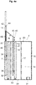
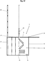
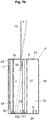
- Fig. 1a represents a cross section of a platform with an integrated protective wall 1.
- the protective wall 1 forms the end of the platform edge 2 or is positioned so close to the platform edge 2 of the platform 4 that when the protective wall 1 is raised, people who are on the platform plateau 23 near the platform Platform edge 2 are located, can not fall into the track area.
- the protective wall 1 is attached to a drive cylinder 3.
- the drive cylinder is connected to a drive device, not shown in the drawing.
- the drive cylinder serves to shift the protective wall 1 from a lowered position into an extended position. In the extended position, the protective wall 1 is in the extended state, which can also be referred to as the protective state. In the lowered position, the protective wall 1 is in the retracted state. In the retracted state, the protective wall 1 for the passengers can be overcome without difficulty, since it does not protrude beyond the area which forms the platform 4.
- An electrically driven drive cylinder, a pneumatically driven drive cylinder or a hydraulically driven drive cylinder serves, for example, as the drive device for the vertical movement.
- the protective wall 1 and the drive cylinder 3 are protected by a sheath 5.
- the casing 5 surrounds the protective wall 1 in the retracted state and the drive device in a cage-like manner.
- the casing 5 is delimited on the track side by a wall which forms the platform edge 2.
- the underside of the casing 5 forms the bottom 24 thereof.
- the top of the shell 5 is at least partially formed by a removable plate 6 which is accessible.
- the casing 5 is delimited by the foundation of the platform 4.
- the envelope 5 therefore represents the outer boundary of a cavity or several support elements 7 are arranged vertically in the cavity.
- the receiving element 9 is arranged between the drive cylinders 3 and forms a vertical guide rail. Two such receiving elements are in the Fig. 1c shown, they are in Fig. 1a or 1b covered by the drive cylinder 3.
- the rod 8 is connected to the protective wall 1 and serves to stabilize the shape of the protective wall and / or to stiffen the protective wall 1. By using one or more such rods 8, the stability of the protective wall can thus be increased against warping, buckling or other deformations.
- a cavity 10 is located behind the drive cylinder 3 and the protective wall 1 in order to be able to carry out repair work in the event of a fault.
- the cavity is part of the shell 5 and is designed as a walk-in free space.
- the compressor and the compressed air tank are also arranged in the cavity 10, which is not shown in the drawing.
- a plate 6 which can be opened upwards.
- the openable plate 6 is supported by supporting elements 7 which are fastened to the bottom 24 of the casing 5.
- the hinged plate 6 is normally closed and can only be opened by specialist personnel.
- the protective wall 1 is flush with the level of the platform plateau when retracted.
- the protective wall 1 rises due to the vertical movement of the drive cylinder 3.
- Pressure sensors can be attached to the upper edge of the protective wall 1, which can stop the upward movement of the protective wall 1 if necessary.
- Fig. 1b shows the construction in the extended protection state.
- the track area and the platform area are mechanically separated by the protective wall 1.
- Fig. 1c shows the first embodiment of the protective wall 1 from the side in the extended state.
- rods 8 lead from the Upper edge of the protective wall 1 to below the lower edge of the protective wall 1.
- the rods 8 are guided in the receiving elements 9, which are designed as tubes.
- the receiving elements 9 are mounted between the drive cylinders 3.
- the receiving elements 9 can be built into the shell 5.
- the length of the rods 8 from the underside of the protective wall 1 to the rod end must not be greater than the height of the drive cylinders 3 in the retracted state.
- the receiving elements 9 have a slot on the side, which corresponds to the height of the extendable protective wall 1. Below the protective wall 1, the rods 8 can be guided through rails at the front and behind the receiving elements 9, which gives them additional stability.
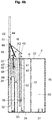
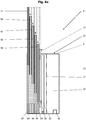
- a protective wall 11 like Fig. 1a , 1b and 1c
- a second protective wall 12 with a greater distance from the platform edge 22 is installed directly on the platform edge 22.
- the protective wall 11 directly on the platform edge 22 is referred to here as the outer protective wall 11.
- the second protective wall 12 with a greater distance from the platform edge 22 is referred to here as the inner protective wall 12.
- the outer protective wall 11 and the inner protective wall 12 are fastened on drive cylinders 13, 14 and stabilized by rods.
- the drive device can be arranged in at least one of the cavities 10, 20, 21 of the casing 15, which is not shown in the drawing.
- On the upper side that is to say at the level of the platform plateau, there is a plate 6 which can be opened up between the protective wall 12 and the casing 15.
- the openable plate 6 is supported by supporting elements 17 which are fastened to the bottom of the casing 15.
- the interior delimited by the shell is divided into the three cavities 10, 20, 21 by the support elements 7, 17.
- the plate 16 which can be opened is supported by supporting elements 7 which rest on the bottom 24 of the Cover 5 are attached.
- the boundary of the cavity 20 on the track side is formed by the platform edge 22.
- the hinged panels 6, 16 are normally closed and can only be opened by specialist personnel.
- the inner protective wall 12 In the retracted state, the inner protective wall 12 is arranged flush with the platform plateau. In the same way, the outer protective wall 11 is arranged flush with the platform plateau in the retracted state.
- the inner protective wall 12 rises due to the vertical movement of the drive cylinder 14.
- the drive cylinder 14 and the inner protective wall 12 are arranged in the interior of the cavity 21 delimited by the support elements 7. Due to the vertical movement of the drive cylinder 13, the outer protective wall 11 rises.
- the drive cylinder 13 and the outer protective wall 11 are arranged inside the cavity 20 which is laterally delimited by the wall which forms the platform edge 22 and by the support elements 7.
- a separating element is provided between the drive cylinder and the protective wall.
- the separating element can be moved with the outer protective wall 11.
- the outer protective wall is arranged slightly offset from the drive cylinder 13 and is guided through an opening in the plate 16.
- Pressure sensors can be attached to the upper edge of each of the protective walls 11, 12, which stop the upward movement of each of the protective walls 11, 12 if necessary.
- the drive cylinders 14 of the inner protective wall 12 are arranged diagonally offset from the drive cylinders 13 of the outer protective wall 11. The chronological sequence of the vertical movement of the two protective walls relative to one another is as follows: when changing passengers, both protective walls 11, 12 are retracted.
- the outer protective wall 11 first moves up.
- the inner protective wall 12 also rises.
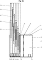
- the advantage of the system according to Fig. 1d compared to a system with only one protective wall 1, as in 1a-1c shown, is that after starting up, no one is on the wrong side of the bulkhead, near the track 12 are located. The prerequisite for this is that the distance between the inner and outer protective walls 11, 12 is not too great or that the space between the protective walls 11, 12 is monitored. In particular, the distance between the rail vehicle and the outer protective wall 11 is at least 5 cm. The distance between the rail vehicle and the outer protective wall 11 should not be more than 10 cm so that no passenger can get caught in the space between the rail vehicle and the outer protective wall 11.
- the distance between the inner protective wall 12 and the outer protective wall 11 is up to 50 cm, preferably up to 30 cm.
- both protective walls 11, 12 are raised, the outer protective wall 11 can lower again. Now only the inner protective wall 12 is in the extended state.
- the advantage is that passing rail vehicles can pass at high speed. An upwardly open channel is thus formed between the inner protective wall 12 and the passing rail vehicle, through which the air displaced by the rail vehicle can flow away and such a high air pressure cannot build up.
- openings on the bulkhead it is possible to provide openings on the bulkhead to relieve this air pressure.
- openings have the disadvantage that they can present a certain danger to people, in particular objects can get caught in the openings.
- the method for operating a protective wall for protecting people from moving rail vehicles in a station area includes the following steps: As soon as the rail vehicle approaches the station area, has reached the station area and / or the approach speed has fallen below 20 km / h, the protective wall 1 begins or the outer protective wall 11 and the inner protective wall 12 begin to lower. When the protective wall 1 or each of the protective walls 11, 12 is completely lowered, the doors of the rail vehicle are opened and a passenger change can take place. As soon as there are no more passengers between the bulkhead and the rail vehicle, the bulkhead 1 or 11 is extended. As soon as the protective wall 1 or 11 is extended, the rail vehicle starts moving again.
- the method for operating a protective wall for the protection of people from moving rail vehicles in a station area includes the following steps: Shortly before the arrival of a rail vehicle with a change of passengers, the outer protective wall 11 rises. As soon as the outer protective wall 11 has been raised, the inner protective wall 12 lowers. Shortly before changing passengers, the outer protective wall 11 lowers again. The passenger change can take place.
- an exemplary embodiment would also be possible which comprises a system with three or more protective walls which function analogously with regard to the time sequence, as has been described in connection with the first or second exemplary embodiment.
- a system with a sliding outer bulkhead can be used. When extended, the outer protective wall moves horizontally on a rail from the edge of the platform into the interior of the platform.
- This variant according to the fourth exemplary embodiment can be used advantageously in particular if high speeds of passing rail vehicles require a large distance between the protective wall and the wagon wall of the rail vehicle.
- the protective wall installed directly on the edge of the platform lowers shortly before the stop of a rail vehicle with a change of passengers and that the rail vehicle only starts moving after the change of passengers after the protective wall is in the extended state again.
- the bulkhead should have lowered before the rail vehicle stops. As soon as the protective wall has completely lowered, it sends a signal to the rail vehicle. If the protective wall is retracted, i.e. the protective wall is in the retracted state, and the rail vehicle is stationary, the doors open.
- the rail vehicle When the passenger change is complete, the driver presses the button for the forced door closure, the rail vehicle sends the command to start up the protective wall.
- the protective wall extends as soon as the driver presses the button for the forced door closing, that is, the protective wall rises before all doors are closed.
- the rail vehicle only sends the signal to raise the protective wall after all the doors have been closed. This would increase safety but extend the length of time the rail vehicle stays on the platform.
- the bulkhead When the bulkhead has reached the extended state, it sends a signal to the locomotive. If all doors are also closed, the shutdown lock in the driver's cab of the locomotive is released and the rail vehicle can start driving.
- the driver wants to take more passengers with him after pressing the button for the forced door lock, he can press the door release button, the protective wall receives the lowering command and the departure process starts again.
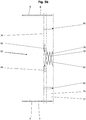
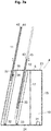
- Fig. 1e shows a variant of the embodiment, which in Fig. 1d is shown.
- Fig. 1e shows a cross section of a platform with two integrated protective walls 11, 12.
- the protective wall 11 forms the end of the platform edge 22 or is positioned so close to the platform edge 22 of the platform 4 that when the protective wall 11 is raised, people who are on the platform plateau 23 located near the platform edge 22, can not fall into the track area.
- the protective wall 11 directly on the platform edge 22 is referred to here as the outer protective wall 11.
- the second protective wall 12 with a greater distance from the platform edge 22 is referred to here as the inner protective wall 12. The further the inner protective wall 12 is from the outer protective wall 11 or the platform edge 22, the better the air pressure that is created by a rail vehicle passing by can be reduced. According to Fig.
- the outer protective wall 11 is connected to a drive cylinder 13.
- the drive cylinder 13 serves to shift the outer protective wall 11 from a lowered position into an extended position.
- the drive cylinder can as in Fig. 1e shown to be multi-stage.
- the outer protective wall 11 can be connected by a driver to a linear vertical drive, which is shown in Fig. 2a is shown.
- the linear vertical drive serves to shift the outer protective wall 11 from a lowered position into an extended position. In the extended position, the outer protective wall 11 is in the extended state, which can also be referred to as the protective state. In the lowered position, the outer protective wall 11 is in the retracted state.
- the inner protective wall 12 is connected to a multi-stage drive cylinder 14.
- the drive cylinder 14 serves to shift the inner protective wall 12 from a lowered position into an extended position.
- the inner protective wall 12 can be carried by a driver be connected to a linear vertical drive, which in Fig. 2a is shown.
- the inner protective wall 12 In the extended position, the inner protective wall 12 is in the extended state, which can also be referred to as the protective state.
- the inner protective wall 12 In the lowered position, the inner protective wall 12 is in the retracted state.
- the inner protective wall 12 can be overcome without difficulty for the passengers, since it does not protrude beyond the area which forms the platform 4.
- the protective walls 11, 12 and their drive cylinders 13, 14 are protected by a sheath 15.
- the casing 15 surrounds the protective walls 11, 12 in the retracted state and the drive devices in a cage-like manner.
- the casing 15 is delimited on the track side by a wall which forms the platform edge 22.
- the bottom of the shell 15 forms the bottom 24 thereof.
- the casing 15 is delimited by the foundation of the platform 4.
- the top of the shell 15 is at least partially formed by the removable plates 6, 16, which are accessible.
- a panel 6 which can be opened upwards between the inner protective wall 12 and the rear wall of the casing 15.
- the panel 6 which is openable is supported by supporting elements 17 which rest on the floor 24 or the rear wall the cover 15 are attached.
- the hinged plate 6 is normally closed and can only be opened by specialist personnel.
- the opening plate 16 is supported by supporting elements 7 which are fastened to the bottom 24 of the casing 15.
- the hinged plate 16 is normally closed and can only be opened by specialist personnel.
- a receiving element 9, for example a tube serves to receive a rod 8 and can serve to guide the rod 8.
- the receiving element forms a vertical guide rail. Two such receiving elements are in the Figure 1f shown.
- the rod 8 is connected to the protective wall 11, 12 and serves to stabilize the shape of the protective wall and / or to stiffen the protective wall 11, 12.
- the use of one or more such rods 8 can thus improve the stability of the protective wall against curvatures , Kinks or other deformations are increased.
- a measuring element 42 for example a pressure sensor, can be attached, by means of which the triggering is carried out may stop the upward movement of the outer bulkhead 11 when necessary.
- a measuring element 43 for example a pressure sensor
- a measuring element 43 can be attached to the upper edge of the inner protective wall 12, by means of which it can be caused that the upward movement of the inner protective wall 12 is stopped if necessary.
- pressure sensors light barriers, active infrared detectors or other sensors can be used.
- a warning element 44 for example a warning light
- a warning element 45 can be attached to the upper edge of the inner protective wall 12, which alerts the passengers to the upward or downward movement of the inner protective wall 12.
- a trigger element 46 for example a push button
- a triggering element 47 can be attached to the side of the inner protective wall 12 facing the track, in order to bring about lowering of the inner protective wall 12 in an emergency in the event that a person leans on the inner protective wall 12 after being raised for some reason Nearer side of the inner bulkhead 12 is located.
- a display element 41 such as, for example, a screen for passenger information such as the next train journey, seat occupancy in the relevant sector, etc., can be attached to the side of the inner protective wall 12 closer to the platform.
- the cavity is part of the shell 15 and is designed as a walk-in free space.
- the cavity can be dispensed with, provided that maintenance and repair work can only be carried out by opening the plate 16.
- a control element 31, for example a remote control box controls the drive cylinders 13, 14 and thus the vertical movements of the outer protective wall 11 and inner protective wall 12.
- the control element 31 is connected, for example, to the signal box and can be controlled by the signal box.
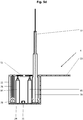
- Fig. 2a shows a cross section of a platform with two integrated protective walls 11, 12.
- the protective wall 11 forms the end of the platform edge 22 or is positioned so close to the platform edge 22 of the platform 4 that when the protective wall 11 is raised, people who are on the platform plateau 23 located near the platform edge 22, can not fall into the track area.
- the protective wall 11 directly on the platform edge 22 is referred to here as the outer protective wall 11.
- the second protective wall 12 with a greater distance from the platform edge 22 is referred to here as the inner protective wall 12.
- the outer protective wall 11 is connected by a driver 34 to a linear vertical drive 32.
- the linear vertical drive 32 serves to shift the outer protective wall 11 from a lowered position into an extended position. In the extended position, the outer protective wall 11 is in the extended state, which can also be referred to as the protective state. In the lowered position, the outer protective wall 11 is in the retracted state. In the retracted state, the outer protective wall 11 for the passengers can be overcome without difficulty, since it does not protrude, or only very slightly, beyond the area which forms the platform 4.
- the inner protective wall 12 is connected by a driver 35 to a linear vertical drive 33.
- the linear vertical drive 33 serves to shift the inner protective wall 12 from a lowered position into an extended position. In the extended position, the inner protective wall 12 is in the extended state, which can also be referred to as the protective state. In the lowered position, the inner protective wall 12 is in the retracted state. In the retracted state, the inner protective wall 12 can be overcome without difficulty for the passengers, since it does not protrude beyond the area which forms the platform 4.
- An electrically driven linear vertical drive serves as the drive device for the vertical movement.
- a drive device can comprise, for example, a linear module with a ball rail guide or a roller guide with a ball screw drive or a toothed belt drive.
- Other guides and drive types are also possible.
- the protective walls 11, 12 and the linear vertical drives 32, 33 are protected by a sheath 15.
- the casing 15 surrounds the protective walls 11, 12 in the retracted state and the drive devices in a cage-like manner.
- the casing 15 can be delimited on the track side by a wall which forms the platform edge 22.
- the sunken protective wall 11 could also assume the function of a track-side outer wall according to each of the exemplary embodiments.
- the bottom of the shell 15 forms the bottom 24 thereof.
- the casing 15 is delimited by the foundation of the platform 4.
- the top of the shell 15 is at least partially formed by the removable plates 6, 16, which are accessible.
- the panel 6 which is openable is supported by supporting elements 17 which rest on the floor 24 or the rear wall the cover 15 are attached.
- the hinged plate 6 is normally closed and can only be opened by specialist personnel.
- the opening plate 16 is supported by supporting elements 7 which are fastened to the bottom 24 of the casing 15.
- the hinged plate 16 is normally closed and can only be opened by specialist personnel.
- a receiving element 9, for example a tube, serves to receive a rod 8 and can serve to guide the rod 8.
- the receiving element forms a vertical guide rail. Two such receiving elements are in the Figure 1f shown.
- the rod 8 is connected to the protective wall 11, 12 and serves to stabilize the shape of the protective wall and / or to stiffen the protective wall 11, 12. The use of one or more such rods 8 can thus improve the stability of the protective wall against curvatures , Kinks or other deformations are increased.
- a measuring element for example a pressure sensor 42
- a measuring element 43 for example a pressure sensor
- a measuring element 43 can be attached to the upper edge of the inner protective wall 12 and can be used to cause the upward movement of the inner protective wall 12 to be stopped if necessary.
- pressure sensors light barriers, active infrared detectors or other sensors can be used.
- a warning element 44 for example a warning light, can be attached to the upper edge of the outer protective wall 11, which alerts the passengers to the upward or downward movement of the outer protective wall 11.
- a warning element 45 for example a warning light
- a trigger element 46 for example a push button
- a warning element 45 can be attached to the upper edge of the inner protective wall 12, which alerts the passengers to the upward or downward movement of the inner protective wall 12.
- a trigger element 46 for example a push button, can be attached to the side of the outer protective wall 11 facing the track, in order to bring about a lowering of the outer protective wall 11 in an emergency in the event that, for some reason, a person is on the outer protective wall 11 after being raised Nearer side of the outer protective wall 11 is located.
- a trigger element 47 for example a push button, can be attached to the side of the inner protective wall 12 facing the track, in order to cause the inner protective wall 12 to be lowered in an emergency in the event that, for some reason, a person leans on the inner protective wall 12 after the inner protective wall 12 has been raised Nearer side of the inner bulkhead 12 is located.
- a display element 41 for example a screen for passenger information such as the next train journey, seat occupancy in the relevant sector, etc., can be attached to the side of the inner protective wall 12 closer to the platform.
- the cavity is part of the shell 15 and is designed as a walk-in free space. The cavity can be dispensed with, provided that maintenance and repair work can only be carried out by opening the plate 16.
- a control element 31 for example a remote control box, controls the linear vertical drives 32, 33 and thus the vertical movements of the outer protective wall 11 and inner protective wall 12.
- the control element 31, such as the remote control box is connected to the signal box and can be controlled by the signal box .
- analog parts are provided with the same reference symbols, so that a detailed description of these parts is unnecessary.
- Fig. 2b shows the platform with the outer protective wall 11 as the end of the platform edge.
- Fig. 2a educates Fig. 2b not the track-side wall 22 of the casing 15 the track-side termination of the platform 4 on the platform plateau, but the outer protective wall 11 forms at least partially the track-side termination even in the retracted state.
- the wall 22 of the casing 15 on the track side extends above the level of the track bed, but does not reach as high as the outer protective wall 11 in the retracted state.
- the advantage is that the distance between the car wall of the rail vehicle and the outer protective wall 11 can also be reduced in the extended state.
- Fig. 2a and Fig. 2b show the state while the rail vehicle is stationary on the platform and the passenger change takes place.
- the outer protective wall 11 and the inner protective wall 12 are in the retracted state.
- the Figures 2c to 2l serve to understand the chronological sequence and thus the process of the vertical movements of the outer protective wall 11 and the inner protective wall 12 after completion of the passenger change, while the passage of rail vehicles without a stop at platform 4 and before the complete standstill of rail vehicles with a stop at platform 4.
- the protective device described is additionally equipped with a mechanical device 51 between the outer protective wall 11 and the inner protective wall 12, in order to press 12 people on the platform 4 onto the side of the inner protective wall 12 closer to the platform while the inner protective wall is being raised.
- the mechanical device 51 which is designed as an extendable intermediate element, is arranged on the platform plateau 23 between the outer protective wall 11 and the inner protective wall 12.
- the pull-out intermediate element 51 rests on the supports 7.
- the pull-out intermediate element 51 is guided during the lifting and lowering process along vertically oriented guide rails in the outer protective wall 11 and along vertically oriented guide rails in the inner protective wall 12.
- the mechanical device 51 thus closes the space between the outer protective wall 11 and the inner protective wall 12.
- Fig. 3c shows the execution of the extendable intermediate element 51 in the extended state and in the contracted state.
- the pull-out intermediate element 51 consists of a frame, a spring element 53 inside and the hinges 52 at the outer corners.
- the frame consists of at least two frame components which can be nested one inside the other and which, even when extended, represent a continuously stable outer shell.
- Each of the frame components can be designed as a hollow body which receives a part of the spring element 53.
- the hollow body can have a circular or rectangular cross section.
- Each of the frame components has an open end and a closed end. At the closed end, one end of the spring element is connected to the frame component.
- the closed end also forms the outer corner to which the hinge 52 is attached, which creates the connection to the protective wall or a drive device which can be activated by the movement of the protective wall.
- the cross-sectional area of each of the two frame components differs from one another, so that one of the frame components can be pushed over the other frame component.
- the two frame components can thus be inserted into one another at their open ends.
- the enlarged extension of the extendable intermediate element 51 is necessary so that the extendable intermediate element 51 receives the desired inclination during the start-up in order to push people safely onto the side of the inner protective wall 12 closer to the platform.
- the pull-out intermediate element 51 can slide through the hinges 52 despite the changed inclination along the guide rails.
- a spring 53 Inside the extendable intermediate element 51 is a spring 53, which pulls the two frame components together slightly and thus helps the extendable intermediate element 51 to regain its original horizontal orientation after the start-up process is complete.
- a driver is a driver with its own drive in the guide rail of the outer protective wall 11 to move the track-side frame component of the pull-out intermediate element 51 upwards.
- the chronological sequence of the vertical movements of the outer protective wall 11, the pull-out intermediate element 51 and the inner protective wall 12 in the embodiment according to FIG Fig. 3a , 3b are as follows:
- the outer protective wall 11 is extended.
- the pull-out intermediate element 51 remains at the level of the platform plateau 23.
- the driver clicks into the guide rail of the outer one Protective wall 11 and remains at the level of platform platform 23.
- the driver moves with its own drive in the guide rail of the outer protective wall 11 the track-side frame component of the extendable intermediate element 51 upwards until the extendable Intermediate element 51 has reached the desired inclination.
- the platform-side frame component of the pull-out intermediate element 51 remains blocked by a termination of the guide rail on the upper edge of the inner protective wall 12 at the level of the platform plateau 23.
- the inclination of the pull-out intermediate element 51 must be sufficiently steep so that people on the platform are safely pushed onto the side of the inner protective wall 12 closer to the platform in the further course. If the extendable intermediate element 51 has a sufficiently large inclination, the linear vertical drive 33 also begins to move the inner protective wall 12 upwards.
- the inner protective wall 12 can extend further. Once the inner protective wall 12 has reached the extended state, the outer protective wall 11 and the pull-out intermediate element 51 can be lowered again to the platform level, that is to say the height of the platform plateau 23. For this it is easiest if the driver in the guide rail of the outer protective wall 11 remains blocked completely at the upper edge of the outer protective wall 11 and so the pull-out intermediate element 51 is moved down together with the outer protective wall 11 by the linear vertical drive 32 to the platform level .
- the driver disengages in the guide rail of the outer protective wall and remains at the platform level.
- the outer protective wall 11 also sinks back into the retracted state before the passenger change.
- Another embodiment has a toothed rack in the guide rail of the outer protective wall 11 and a toothed wheel with an electric motor on the side of the extendable intermediate element 51 near the track.
- the gearwheel with an electric motor is part of the track-side frame component of the pull-out intermediate element 51.
- the energy supply for the electric motor is ensured by an electric cable which is led to the electric motor through a hole in the frame component of the pull-out intermediate element 51 near the track.
- the chronological sequence of the vertical movements of the outer protective wall 11, the support element 70 and the inner protective wall 12 as well as the unfolding and folding movements of the fold-out flap 65 in the embodiment according to FIG Fig. 4c are as follows:
- the outer protective wall 11 is extended. If the outer protective wall 11 is in the extended state or extended so far that no more people can fall from the platform 4 into the track area, the linear vertical drive 72 moves the support element 70 upwards until the fold-out flap 65 is completely above the platform plateau 23. If the fold-out flap 65 is located completely above the platform plateau 23, the upward movement of the support element 70 stops and the fold-out flap 65 begins to fold out.
- the unfolding movement of the fold-out flap 65 pushes people on the platform 4 onto the side of the inner protective wall 12 closer to the platform.
- the fold-out flap 65 When the fold-out flap 65 is unfolded, there is a small gap between the lower end of the fold-out flap 65 and the platform plateau 23.
- the greater the distance between the outer protective wall 11 and the inner protective wall 12 and the flatter the inclination of the fold-out flap 65 in the unfolded state the larger the gap between the fold-out flap 65 in the unfolded state and the platform plateau 23.
- the length of the fold-out flap 65 must be adapted to the distance between the outer protective wall 11 and the inner protective wall 12.
- Fig. 4c offers the possibility for very steep angles of the fold-out flap 65 in the unfolded state, and additionally the fold-out flap 65 projects beyond the inner protective wall 12 in the unfolded state, this gap can be minimized. If the railway operator wishes to completely close this gap between the lower end of the fold-out flap 65 in the unfolded state and the platform plateau 23, the design of the fold-out flap 65 can be such that the fold-out flap 65 increases its extent during the unfolding, i.e. also an extendable one Contains item.
- the linear vertical drive 33 begins to move the inner protective wall 12 upwards. In the further course, the inner protective wall 12 and the support element 70 move upwards at the same speed. If the inner protective wall 12 has been extended so far that it safely separates the track area from the platform area, the linear vertical drive 33 stops the upward movement of the inner protective wall 12. The support element 70 moves a little further upwards until the fold-out flap 65 can be folded in. The fold-out flap 65 is completely folded in and the support element 70 can be retracted completely. Rail vehicles can now drive through the station at high speed.
- the embodiments according to 5a - 5f are alternatives with limited space below platform platform 23 for the in 1-4 described protective wall systems. Is there enough space in the underground below platform platform 23 for the installation of a Figures 1 -4 bulkhead system described, it is advantageous to a bulkhead system according to 1-4 to install because the components are easy to implement. However, there may be places along a platform where, for various reasons, there is not enough space in the underground below platform platform 23 for a protective wall system with linear vertical drives 1-4 is available, for example in the area of station underpasses, where the passengers cross under the tracks. Feature of the embodiments according to 5a - 5f is that the protective walls have a much smaller vertical extent when retracted than when extended.
- Fig. 5a shows a cross section of a platform with two integrated multi-part extendable protective walls 76, 77.
- the outer protective wall 76 consists of multi-part extendable plates. In the retracted state, the panels are arranged side by side, in the extended state they are slightly offset one above the other. When extended, the panels must provide a continuous closure on the side facing the passengers near the platform; the panels themselves can be hollow on the inside and open on the side closer to the track.
- the plate which is the tallest in the extended state, is connected to a drive mechanism 78 for the extension and retraction movements.
- the drive mechanism is at least largely inside the outer protective wall 76.
- a scissor drive, a telescopically extendable cylinder or other drives are possible as drive mechanism 78.
- the inner protective wall 77 also consists of plates that can be pushed out in several parts. In the retracted state, the panels are arranged side by side, in the extended state they are slightly offset one above the other. When extended, the plates on the side facing the platform near the platform must represent a continuous closure; the plates themselves can be hollow on the inside and open on the side near the track. The plate, which is the tallest in the extended state, is connected to a drive mechanism 79 for the extension and retraction movements.
- the drive mechanism is at least largely inside the inner protective wall 77.
- a scissor drive, a telescopically extendable cylinder or other drives are possible as the drive mechanism 79. If both sides of the inner protective wall 77 are sealed off by plates, this has the advantage of protection against dirt and ingress of dust. If only the side of the inner protective wall 77 facing the platform has a panel closure and the side facing the track is open, this has the advantage that repair work can be carried out more easily.
- Fig. 5a shows the state with the outer protective wall 76 retracted and the inner protective wall 77 extended, that is to say the state in which rail vehicles can drive through the platform at high speed.
- the chronological sequence of the extension and retraction movements of the outer protective wall 76 and inner protective wall 77 after completion of the passenger change, during the passage of rail vehicles without a stop at platform 4 and before the complete standstill of rail vehicles with a stop at platform 4 are the same as in FIG 2a-2m illustrated embodiment.
- Fig. 5b shows the embodiment with a multi-part extendable protective wall 76, 77 from the side in the retracted state. It is driven by a scissor mechanism comprising two scissor carriers 78, 79 by a telescopically extendable cylinder 80 or by another drive. In the Fig. 5b the scissor carriers 78, 79 are moved by the cylinders 81.
- a receiving element 9 for example a tube, is arranged to the left and right of the station underpass 83.
- the receiving element 9 serves to receive a rod 8 and can serve to guide the rod 8.
- the receiving element 9 forms a vertical guide rail.
- the rod 8 is connected to the protective wall 76, 77 and serves to stabilize the shape of the protective wall 76, 77 and / or to stiffen the protective wall 76, 77.
- the use of one or more such rods 8 can thus increase the stability the protective wall 76, 77 against bulges, kinks or other deformations can be increased.
- Fig. 5c shows the embodiment with a multi-part extendable protective wall 76, 77 from the side in the extended state.
- Fig. 5d shows a cross section of a platform with two integrated multi-part extendable protective walls 76, 77 and one as in Fig. 3d described extendable intermediate element 51 in between.
- Fig. 5d the inclination and the vertical movement of the extendable intermediate element 51 by the telescopic extendable cylinders 84, 85 executed.
- the telescopically extendable cylinder 84 is connected to the frame component closer to the track
- the telescopic extendable cylinder 85 is connected to the frame component closer to the platform.
- the extendable intermediate element 51 can be guided during the lifting and lowering process along vertically oriented guide rails in the side of the outer protective wall near the platform and / or along vertically oriented guide rails in the side near the track of the inner protective wall.
- the chronological sequence of the vertical movements of the outer protective wall 76 which can be extended in several parts, the extendable intermediate element 51 and the inner protective wall 77 which can be extended in several parts Fig. 5d is the same as for Fig. 3d described.
- Fig. 5e shows a cross section of a platform with two integrated multi-part extendable protective walls 76, 77 and one as in Fig. 4c described fold-out flap 65, which is mounted on a separate support element 70.
- the fold-out flap 65 has the purpose of pushing 12 people on the platform 4 onto the side of the inner protective wall closer to the platform during the extension of the inner protective wall which can be extended in several parts.
- the vertical movement of the support element 70 is carried out by a drive mechanism 86, which can consist of a scissor mechanism, a telescopically extendable cylinder or other drive forms which have a much smaller vertical extent in the retracted state than in the extended state.
- a sensor and a fixation on the rear wall of the support element 70 ensure that the support element 70 is only retracted when the fold-out flap 65 is in the folded state.
- the possible drive for the fold-out movement of the fold-out flap 65 is the same as in FIG Fig. 4c described.
- the length of the fold-out flap 65 corresponds to at least a length which is suitable for being able to cover the distance between the outer protective wall 76 which can be extended in several parts and the inner protective wall 77 which can be extended in the inclined, unfolded state.
- the design of the fold-out flap 65 can, however, also be longer and protrude beyond the inner protective wall 77, which can be extended in several parts, while the inner protective wall 77 can be extended.
- the support member 70 can be vertical aligned guide rails in the bottom plate near the platform of the multi-part extendable outer protective wall 76. In the area of station underpasses, it is also possible for the support element 70 to be guided on the left and right of the station underpass along vertically oriented guide rails in the side of the outer protective wall 11 closer to the platform.
- the chronological sequence of the vertical movements of the outer protective wall 76, which can be extended in several parts, of the support element 70 and of the inner protective wall 77 which can be extended in several parts, as well as the unfolding and retracting movements of the fold-out flap 65 Fig. 5e and the operation of the drive 66 are the same as in Fig. 4c described.
- Fig. 5f represents a cross section of a platform in which the outer protective wall 88 and the inner protective wall 89 consist of pluggable wall elements.
- This embodiment is advantageous if there is very little space below platform platform 23. Because the pluggable wall elements can be stacked one above the other in the retracted state, the vertical extent in the retracted state is very small. The pluggable wall elements are held together by a continuous rope.
- the top wall element is connected to a drive, for example a telescopically extendable cylinder. In the area of station underpasses, the top wall element can also be pulled up on a vertical bar, the vertical bars can be placed to the left and right of the station underpass, i.e.
- a system with a pull-out intermediate element 51 can be used between the protective walls 88, 89 Fig. 3d or a system with a fold-out flap 65 as in Fig. 4c be installed.
- Reference numerals which are shown in this exemplary embodiment but not described correspond to the corresponding components in the preceding figures.
- extendable intermediate walls 90, 91, 92, 93 are between the outer protective wall 11 and the inner protective wall 12 in order to push 12 people on the platform onto the side of the inner protective wall 12 closer to the platform while the inner protective wall is being raised.
- extendable partition walls 90, 91, 92, 93 between the outer protective wall 11 and the inner protective wall 12 a system with only one, two, three or five or more extendable intermediate walls between the outer protective wall 11 and the inner protective wall 12 would also be possible .
- the extendable partitions 90, 91, 92, 93 must represent a continuous closure on the side near the platform facing the passengers, the partitions 90, 91, 92, 93 themselves can be hollow on the inside and open on the side near the track.
- Each extendable partition 90, 91, 92, 93 is connected to a drive mechanism 94 for the extension and retraction movement.
- the drive mechanism 94 is at least largely inside each individual partition 90, 91, 92, 93.
- a scissor drive, a telescopically extendable cylinder or other drives are possible as the drive mechanism 94.
- the drive mechanism of the outer protective wall 11 is also at least largely arranged in the interior of the outer protective wall 11.
- the inner protective wall 12 can be driven by a drive mechanism inside the inner protective wall 12 or by a linear vertical drive 33. Since in the embodiment after Fig. 6a the extendable intermediate walls 90, 91, 92, 93 between the outer protective wall 11 and the inner protective wall 12 perform the same function as the extendable intermediate element 51 in Fig. 3d or the fold-out flap 65 in Fig. 4c the chronological sequence of the vertical movements of the outer protective wall 11, the intermediate walls 90, 91, 92, 93 and the inner protective wall 12 is as follows: When the passenger change is completed, the outer protective wall 11 is extended.
- the extendable intermediate wall 90 begins to extend directly next to the outer protective wall 11. If the extendable partition 90 is partially extended, begins extend the extendable intermediate wall 91 directly next to the extendable intermediate wall 90, the extendable intermediate wall 90 also moves upward. If the extendable intermediate wall 91 is partially extended, the extendable intermediate wall 92 begins to extend directly next to the extendable intermediate wall 91 and so on to the extendable intermediate wall directly next to the inner protective wall 12. If the extendable intermediate wall 93 directly next to the inner protective wall 12 is in the extended state, the inner protective wall 12 can extend. The inner protective wall is moved via a vertical drive 33.
- the outer protective wall 11 and the extendable intermediate walls 90, 91, 92, 93 can lower again. At this time, only the inner protective wall 12 is in the extended protective state, rail vehicles can drive through the platform at high speed. If the last rail vehicle without a stop at the platform has left the track area on the platform and the next rail vehicle will be a rail vehicle with a stop at the platform and change of passengers, as in Fig. 2h shown - extend the outer protective wall 11. At this time, the partitions 90, 91, 92, 93 remain in the retracted state since no people have to be pushed away. After the inner protective wall 12, as in Fig. 2i has shown, lowered, the outer protective wall 11 also sinks back into the retracted state before the passenger change.
- the embodiment according to Fig. 6b is an alternative to the embodiment of FIG Fig. 6a with limited space below the platform plateau 23.
- multi-part extendable outer protective wall 76 and the multi-part extendable inner protective wall 77 multi-part extendable intermediate walls 96, 97, 98, 99 in order to lift up the multi-part extendable inner protective wall 77 people on platform 4 to the side of the multi-part extendable inner protective wall 77 closer to the platform to push away.
- Feature of the embodiment according to Fig. 6b is that the multi-part extendable protective walls 76, 77 and the multi-part extendable intermediate walls 96, 97, 98, 99 in the retracted state a much smaller vertical Have expansion than in the extended state.
- each partition 96, 97, 98, 99 is connected to a drive mechanism 95.
- the drive mechanism 95 is located at least largely in the interior of each individual partition wall 96, 97, 98, 99 which can be extended in several parts.
- the drive mechanism 78 of the outer protective wall 76 which can be extended in several parts is at least largely in the interior of the outer protective wall 76 which can be extended in several parts, the drive mechanism 79 in the inner part which can be extended in several parts Protective wall 77 is at least largely inside the inner protective wall 77, which can be extended in several parts.
- a scissor drive, a telescopically extendable cylinder or other drives are possible as drive mechanisms 78, 79, 95. In the embodiment according to Fig.
- Fig. 7a shows a version for platforms which are in the area of strongly inclined track curves.
- track curves can have a lateral inclination; accordingly, in the area of inner track curves, the rail vehicles can have a lateral inclination.
- the outer protective wall 11 and the inner protective wall 12 can also be inclined.
- Fig. 7a shows a cross section of a platform with two integrated inclined protective walls 11, 12.
- the platform edge 22, the outer protective wall 11, the linear vertical drive 32, the inner protective wall 12 and the linear vertical drive 33 are inclined.
- the linear vertical drives 32, 33 are fixed to the bottom 24 of the casing 15.
- 4a - 4c or 6a described device can be installed in order to push 12 people on the platform 4 to the side of the inner protective wall 12 closer to the platform before or during the raising of the inner protective wall.
- the chronological sequence of the movements of the outer protective wall 11 and the inner protective wall 12 after completion of the passenger change, while the passage of rail vehicles without a stop at platform 4 and before the complete standstill of rail vehicles with a stop at platform 4 are the same as in FIG 2a-2m illustrated embodiment.
- FIG. 7b , 7c shows an embodiment in which the inner protective wall 12 can be inclined inwards in the direction of the platform in the extended state.
- a tilting device is provided in order to transfer at least one of the protective walls 11, 12 from a vertical position into an inclined position.
- the linear vertical drive 33 of the inner protective wall 12 is mounted on a slide 101 which can move along a rail by means of a linear horizontal drive.
- the carriage 101 or the linear vertical drive 33 has hinges at the lower corners.
- the inner protective wall 12 tilts back into the vertical starting position as soon as the slide 101 moves back into its starting position in the direction of the rear wall of the casing 15.
- the linear vertical drive 32 of the outer protective wall 11 is fixed on the bottom 24 of the casing 15, the outer protective wall 11 always has a vertical orientation.
- Between the outer protective wall 11 and the inner protective wall 12 can be as in the 3a-3d , 4a - 4c or 6a described device can be installed in order to push 12 people on the platform 4 to the side of the inner protective wall 12 closer to the platform before or during the raising of the inner protective wall.
- the inner protective wall 12 begins as in Fig. 7b shown tending inward towards the platform.
- the carriage 101 and thus also the lower part of the linear vertical drive 33 moves along the rail 102 in the direction of the platform edge 22.
- the fulcrum of the inner protective wall 12 is on the platform plateau 23, the inner protective wall 12 is on the platform plateau 23 between the plate 16 and the plate 6 fixed.
- the rotary movement can be facilitated by a notch in the side of the inner protective wall 12 near the platform on the platform plateau 23 and a counterpart which can be extended from the plate 6.
- FIG. 8a and 8b show a top view of an embodiment with retaining elements which prevent passengers from getting into the space between the inner and outer protective wall.
- These retaining elements can be designed, for example, as extendable bollards 103 between the outer protective wall 11 and the inner protective wall 12, the extendable bollards 103 are placed as a lateral end of the protective wall system. It may be that the railway operator wants to equip only part of the platform with a protective wall system for cost reasons and wants to leave the other part of the platform open as before.
- the protective wall system has a side closure with extendable bollards 103.
- extendable bollards can also form the side closure.
- Each post can have its own drive connected or similar to a fork, the posts can be mounted on a beam so that a drive would move many posts at the same time.
- the distance between the side bollards 103 should be sufficiently small that small children cannot pass it. If one like in the 3a-3d or Fig.
- the device described is installed in order to push 12 people on the platform 4 onto the side of the inner protective wall 12 closer to the platform before or during the raising of the inner protective wall, the extendable bollards 103 as in FIG Fig. 8b shown placed next to the extendable intermediate element 51 or next to the extendable intermediate walls 90, 91, 92, 93. If one like in the 4a-4c described device installed, the extendable bollards 103 next to or advantageously as in Fig. 8a shown placed within the space covered by the flap 65.
- the device described is the chronological sequence of the vertical movements of the lateral bollards 103, the outer protective wall 11 and the inner protective wall 12 as well as the unfolding and folding movements of the fold-out flap 65 in the embodiment according to FIG Fig. 8a as follows:
- the linear vertical drive 32 moves the outer protective wall 11 upwards. If the fold-out flap 65 is completely above the platform plateau 23, the fold-out flap 65 begins to fold out.
- the unfolding movement of the fold-out flap 65 pushes people on the platform 4 onto the side of the inner protective wall 12 closer to the platform.
- the side bollards 103 are now arranged under the fold-out flap 65.
- the extending movements of the lateral bollards 103 follow the unfolding movement of the fold-out flap 65, that is to say the lateral bollard closest to the track extends first, the lateral bollard closest to the platform last.
- a gap between the fold-out flap 65 and the side bollards 103 can thereby be avoided.
- the side bollards 103 can also be used as a support for the unfolding movement of the fold-out flap 65.
- the fold-out flap 65, the side bollards 103 and the inner protective wall 12 move upwards at the same speed. Is the inner protective wall 12 extended so far that it safely moves the track area from If the platform area separates, the linear vertical drive 33 stops the upward movement of the inner protective wall 12.
- the upward movement of the lateral bollards 103 is also stopped.
- the fold-out flap 65 moves up a little further until it can be folded in.
- the fold-out flap 65 is completely folded in and the outer protective wall 11 and, depending on the embodiment, also the support element 70 can be completely retracted.
- Rail vehicles can now drive through the platform at high speed. If the last rail vehicle without a stop at the platform has left the track area on the platform and the next rail vehicle will be a rail vehicle with a stop at the platform and change of passengers, as in Fig. 2h shown extend the outer protective wall 11.
- the fold-out flap 65 remains in the folded state.
- the outer protective wall 11 also lowers again into the retracted state before the passenger change.
- the track-side frame component of the extendable intermediate element 51 is moved upwards by the driver or the rod 54 until the inclination is sufficiently large is so that in the further course people on the platform are safely pushed onto the side of the inner protective wall 12 closer to the platform. It is advantageous if the side bollards 103 follow the extension movement of the extendable intermediate element 51, that is to say the side bollard closest to the track extends first, the side bollard closest to the platform last. This can create a gap between the extendable intermediate element 51 and the lateral ones Bollards 103 can be avoided.
- the extendable intermediate element 51, the side bollards 103 and the inner protective wall 12 move upwards at the same speed.
- the outer protective wall 11 and the pull-out intermediate element 51 can lower again down to the platform plateau.
- Rail vehicles can now drive through the platform at high speed. If the last rail vehicle without a stop at the platform has left the track area on the platform and the next rail vehicle will be a rail vehicle with a stop at the platform and change of passengers, as in Fig. 2h shown extend the outer protective wall 11.
- the outer protective wall 11 also lowers again into the retracted state before the passenger change.
- the chronological sequence of the vertical movements of the side bollards 103, the outer protective wall 11, the extendable intermediate walls 90, 91, 92, 93 and the inner protective wall 12 is the same as when installing one as in the 3a-3d described facility.
- the extension movements of the lateral bollards 103 advantageously follow the extension movements of the extendable partition walls 90, 91, 92, 93.
Claims (15)
- Dispositif de protection pour la protection des personnes dans une zone de gare contre les véhicules ferroviaires en mouvement, la zone de gare contenant au moins une plate-forme (4), la plate-forme (4) contenant au moins un bord de plate-forme (2, 22) et des voies pour un véhicule ferroviaire sont disposées sur un premier côté du bord de plate-forme (2,22) et un plateau de plate-forme (23) existe sur un deuxième côté du bord de plate-forme (2, 22), qui est conçu comme une zone d'attente pour personnes, une paroi de protection (11, 12, 76, 77, 88, 89) étant située directement à côté ou près du bord de la plate-forme (2, 22) et réglable entre un état rétracté et un état étendu de telle manière que à l'état étendu de la paroi de protection (11, 12, 76, 77, 88, 89), un accès aux voies est obstrué, à l'état rétracté, l'accès aux voies est libre, caractérisé en ce que la paroi de protection comprend une paroi de protection intérieure (12, 77, 89) et une paroi de protection extérieure (11, 76, 88), la paroi de protection intérieure (12) étant installée à une plus grande distance du bord de la plate-forme (2, 22), la paroi de protection étant logée dans une cavité (10, 20) à l'état rétracté, la cavité (10, 20) étant disposée sous le plateau de la plate-forme (23).
- Dispositif de protection selon la revendication 1, par lequel la paroi de protection extérieure (11, 76, 78) est installée entre le bord de plateforme (22) et la paroi de protection intérieure (12, 77, 89) ou la paroi de protection extérieure (11, 76, 88) forme le bord de la plate-forme (22) ou est installé directement à côté du bord de la plate-forme (22).
- Dispositif de protection selon l'une des revendications 1 ou 2, en ce que la paroi de protection (11, 12, 76, 77, 88, 89) contient au moins chacune un dispositif d'entraînement (13, 14, 32, 33, 78, 79, 84, 85), par lequel un élément de commande (31) pour la commande du dispositif d'entraînement (13, 14, 32, 33, 78, 79, 84, 85) peut être prévu, qui peut être connecté à un verrouillage, grâce à quoi le dispositif d'entraînement (13, 14, 32, 33, 78, 79, 84, 85) peut contenir au moins un vérin d'entraînement (13, 14, 78, 79, 84, 85) ou un entraînement vertical (32, 33).
- Dispositif de protection selon l'une quelconque des revendications précédentes, dans lequel un élément de plaque amovible (6) est prévu pour fermer la cavité (10, 20), de sorte qu'un pilier (7, 17) est disposé dans la cavité (10, 20), qui peut servir de support à l'élément de plaque amovible (6).
- Dispositif de protection selon l'une quelconque des revendications précédentes, dans lequel la paroi de protection (11, 12, 76, 77, 88, 89) à l'état étendu est mobile du bord de plate-forme (2, 22) en direction du plateau de plate-forme (23).
- Dispositif de protection selon l'une quelconque des revendications précédentes, par lequel un élément capteur (42, 43), un élément avertisseur (44, 45), un élément déclencheur (46, 47) ou un élément indicateur (41) est disposé au moins au niveau de l'une des parois de protection (11, 12, 76, 77, 88, 89).
- Dispositif de protection selon l'une quelconque des revendications précédentes, en ce qu'entre la paroi de protection extérieure (11, 76, 88) et la paroi de protection intérieure (12, 77, 89) un système mécanique (51) est agencé pour sceller l'espace entre la paroi de protection extérieure (11, 76, 88) et la paroi de protection intérieure (12, 77, 89), en ce que le système mécanique (51) peut être formé comme un élément intermédiaire extensible, l'élément intermédiaire extensible pouvant comprendre un cadre qui comprend deux composants de cadre qui contiennent un élément ressort (53).
- Dispositif de protection selon l'une quelconque des revendications précédentes, en ce que l'une des parois de protection (11, 12, 76, 77, 88, 89) est équipée d'un volet articulé (65) par lequel l'espace entre les deux parois de protection est recouvrable, le volet articulé (65) pouvant être intégré dans la paroi de protection extérieure (11, 76, 88) ou être fixé sur un élément de support séparé (70) et / ou un capteur est prévu sur la paroi de protection ou au volet articulé (65).
- Dispositif de protection selon l'une quelconque des revendications précédentes, en ce qu'une fixation est prévue sur la paroi arrière de la paroi de protection extérieure (11, 76, 88) ou sur l'élément de support (70), de sorte que la paroi de protection extérieure (11, 76, 88) ou l'élément de support (70) ne peut être abaissé que si le volet articulé (65) est dans un état plié.
- Dispositif de protection selon la revendication 9, en ce que la longueur du volet articulé (65) correspond au moins à la distance entre la paroi de protection extérieure (11, 76, 88) et la paroi de protection intérieure (12, 77, 89), en ce que le mouvement de poussée du volet articulé peut être provoqué au moins par l'une des options suivantes: par un entraînement (66) lors du montage du volet articulé (65) sur la paroi de protection extérieure à l'extrémité supérieure du volet articulé (65), par un poteau horizontal rotatif, le poteau horizontal rotatif étant relié à un entraînement en dessous du volet articulé (65), par un élément ressort, par un poteau auxiliaire (67), par une borne escamotable.
- Dispositif de protection selon l'une quelconque des revendications précédentes, en ce qu'au moins une des parois de protection intérieures ou extérieures (76, 77, 88, 89) est conçue en plusieurs parties, grâce à quoi une pluralité de parois intermédiaires escamotables (90, 91, 92, 93) peuvent être disposés entre la paroi de protection extérieure (11, 76, 88) et la paroi de protection intérieure (12, 77, 89), en ce qu'au moins une des parois de protection intérieures ou extérieures (11, 12, 76, 77, 88, 89) peut former un angle inférieur à 90 ° avec le plan du plateau de plate-forme (23) ou un dispositif d'inclinaison est prévu de sorte qu'au moins une des parois de protection intérieure ou extérieure (11, 12, 76, 77, 88, 89) sont convertibles d'une position verticale à une position inclinée, grâce à quoi des éléments de retenue peuvent être disposés dans l'espace entre la paroi de protection intérieure et extérieure (11, 12, 76, 77, 88, 89).
- Dispositif de protection selon l'une quelconque des revendications précédentes, en ce que la paroi de protection intérieure (12, 77, 89) peut comprendre une paroi de protection continue ou des poteaux rapprochés.
- Procédé pour faire fonctionner un dispositif de protection pour la protection des personnes contre le déplacement de véhicules ferroviaires dans une zone de gare, en ce que la zone de gare contient au moins une plate-forme (4), la plate-forme (4) contenant au moins un bord de plate-forme (2, 22), dans lequel, dans un premier temps, une paroi de protection (11, 12, 76, 77, 88, 89) commence à être abaissé dès que le véhicule ferroviaire approche de la zone de la gare et / ou que la vitesse d'approche a diminué en dessous de 20 km / h et / ou un signal d'actionnement pour actionner un dispositif d'entraînement (3, 13, 14) pour la paroi de protection est reçu, dans une deuxième étape la paroi de protection (11, 12, 76, 77, 88, 89) est complètement abaissée dans le état rétracté lorsque le véhicule ferroviaire atteint sa position d'arrêt, dans une troisième étape après avoir atteint l'état rétracté, les portes du véhicule ferroviaire sont ouvertes afin qu'un échange de passagers puisse avoir lieu, dans une quatrième étape, un signal de sortie de l'état rétracté est transmis au dispositif d'entraînement de la paroi de protection dès qu'aucun passager n'est situé plus entre la paroi de protection et le véhicule ferroviaire et un signal de fermeture des portes du véhicule ferroviaire a été transmis, de sorte que la paroi de protection est levée à l'état étendu et dans une cinquième étape, le véhicule ferroviaire peut recommencer à se déplacer dès que la paroi de protection a atteint l'état étendu, caractérisée en ce que la paroi de protection comprend une paroi de protection intérieure (12, 77, 89) et une paroi de protection extérieure (11, 76, 88), de sorte que peu de temps avant l'entrée du véhicule ferroviaire, la paroi de protection extérieure (11, 76, 88) est soulevée, dès que la paroi de protection extérieure (11, 76, 88) a été levée, la paroi de protection intérieure (12, 77, 89) est abaissée et peu de temps avant échange de passagers, la paroi de protection extérieure (11, 76, 88) est à nouveau abaissée à l'état rétracté de sorte qu'un échange de passagers puisse avoir lieu, après quoi, après l'échange de passagers, le véhicule ferroviaire ne commence à se déplacer que lorsque la paroi de protection extérieure (11, 76, 88) est à nouveau dans l'état étendu.
- Procédé selon la revendication 13, en ce que le signal de levée de la paroi de protection (11, 12, 76, 77, 88, 89) est lié au signal de fermeture de porte des portes du véhicule ferroviaire et / ou du dispositif de protection est équipé d'un émetteur et / ou d'un récepteur pour interagir avec un véhicule ferroviaire et / ou le processus de levage de la paroi de protection extérieure (11, 76, 88) est déclenché par une fermeture forcée de la porte dans le véhicule ferroviaire et / ou l'abaissement de la paroi de protection extérieure (11, 76, 88) est déclenchée par un système de commande d'ouverture de porte, grâce à quoi la paroi de protection extérieure (11, 76, 88) commence à être soulevée avant que toutes les portes du véhicule ferroviaire ne soient fermées ou que la porte extérieure la paroi de protection (11, 76, 88) est levée après la fermeture de toutes les portes du véhicule ferroviaire, au moins l'une des parois de protection contient des capteurs qui détectent la vitesse du véhicule ferroviaire et / ou la distance du véhicule ferroviaire de sa position d'arrêt.
- Procédé selon l'une quelconque des revendications 13 ou 14, en ce qu'après l'échange de passagers et après que la paroi de protection extérieure (11, 76, 88) ont été levés à l'état étendu, un système mécanique (51) est déplacé jusqu'à ce que le système mécanique (51) a une inclinaison suffisamment forte pour qu'au cours du procédé ultérieur, les personnes se tenant sur la plate-forme soient poussées en toute sécurité vers le côté orienté vers la plate-forme de la paroi de protection intérieure (12, 77, 89), grâce à quoi le système mécanique (51) est déplacé ensemble avec la paroi de protection intérieure lorsque la paroi de protection intérieure (12, 77, 89) est soulevée et dès que la paroi de protection intérieure (12, 77, 89) a atteint l'état étendu, la paroi de protection extérieure (11, 76, 88) et le système mécanique (51) commence à être abaissé au niveau du plateau de plate-forme (23) par lequel la paroi de protection extérieure (11, 76, 88) est soulevée avant qu'un véhicule ferroviaire n'atteigne la zone de la gare, grâce à quoi le système mécanique (51) reste au niveau du plateau de plate-forme (23), après quoi la paroi de protection intérieure (12, 77, 89) abaisse également la paroi de protection extérieure (11, 76, 88) dans l'état rétracté avant l'échange de passagers, le système mécanique (51) comprenant un élément intermédiaire extensible (51), un volet articulé (65) ou une pluralité de parois intermédiaires (90, 91, 92, 93), qui peuvent être soulevées par un entraînement, le système mécanique (51) pouvant comprendre un élément de châssis orienté sur la voie et un élément de châssis orienté sur la plate-forme, en ce que l'élément de châssis orienté sur la voie et l'élément de châssis orienté sur la plate-forme et la paroi de protection intérieure (12, 77, 89) se déplacent vers le haut à la même vitesse, de sorte que l'inclinaison du système mécanique (51) reste constant.
Applications Claiming Priority (2)
| Application Number | Priority Date | Filing Date | Title |
|---|---|---|---|
| CH11282013 | 2013-06-14 | ||
| PCT/EP2014/061408 WO2014198579A1 (fr) | 2013-06-14 | 2014-06-02 | Paroi de protection pour la protection de personnes de véhicules ferroviaires en circulation |
Publications (2)
| Publication Number | Publication Date |
|---|---|
| EP3007953A1 EP3007953A1 (fr) | 2016-04-20 |
| EP3007953B1 true EP3007953B1 (fr) | 2020-04-08 |
Family
ID=50877307
Family Applications (1)
| Application Number | Title | Priority Date | Filing Date |
|---|---|---|---|
| EP14727533.3A Active EP3007953B1 (fr) | 2013-06-14 | 2014-06-02 | Paroi de protection pour la protection de personnes de véhicules ferroviaires en circulation |
Country Status (6)
| Country | Link |
|---|---|
| US (1) | US10053114B2 (fr) |
| EP (1) | EP3007953B1 (fr) |
| CN (1) | CN105658496B (fr) |
| AU (1) | AU2014280380B2 (fr) |
| CA (1) | CA2916022C (fr) |
| WO (1) | WO2014198579A1 (fr) |
Families Citing this family (16)
| Publication number | Priority date | Publication date | Assignee | Title |
|---|---|---|---|---|
| AT515895B1 (de) * | 2014-06-02 | 2016-08-15 | Innova Patent Gmbh | Seilbahnanlage zur Beförderung von Personen |
| US9797182B2 (en) * | 2014-08-12 | 2017-10-24 | Amesbury Group, Inc. | Powered window system |
| US9517778B2 (en) * | 2015-03-27 | 2016-12-13 | Kenneth I. Thompson | Railway passenger gate assembly |
| US10384691B2 (en) * | 2015-04-08 | 2019-08-20 | National Railroad Passenger Corporation | Method and system for setback modular platform with integrated shuttle platform |
| CN104828096B (zh) * | 2015-04-10 | 2017-07-18 | 金基德 | 一种铁路站台活动护栏 |
| CN104925068A (zh) * | 2015-07-01 | 2015-09-23 | 上海嘉成轨道交通安全保障系统股份公司 | 一种轨道交通站台安全踏板 |
| CN105756492B (zh) * | 2016-04-22 | 2018-06-19 | 江苏浔丰轨道交通科技有限公司 | 地铁屏蔽门紧急避险结构 |
| US20180016809A1 (en) * | 2016-07-18 | 2018-01-18 | Patrick Hyland | Retractable Fence Assembly |
| JP2019059459A (ja) * | 2017-04-11 | 2019-04-18 | 隆人 内藤 | 昇降柵及び昇降式ホーム柵を有するプラットホーム構造体 |
| CN108189846B (zh) * | 2018-02-08 | 2019-10-15 | 江苏建筑职业技术学院 | 一种站台限界缝隙无障碍衔接装置 |
| ES1223018Y (es) * | 2018-08-02 | 2019-04-08 | Uzal Aurelio Francos | Barrera retractil perfeccionada para la proteccion de personas |
| US10933891B2 (en) * | 2018-10-16 | 2021-03-02 | International Business Machines Corporation | Railway station platform enhancement |
| CN111383457B (zh) * | 2018-12-30 | 2021-02-09 | 浙江宇视科技有限公司 | 车位状态检测方法及装置、设备及存储介质 |
| US11466461B1 (en) * | 2019-04-27 | 2022-10-11 | Luis Jones | Actuatable assemblies |
| CN111957572B (zh) * | 2020-08-17 | 2022-09-16 | 重庆德能再生资源股份有限公司 | 铅酸电池回收用铅原料与外壳分离装置 |
| CN116220515B (zh) * | 2023-02-07 | 2023-10-27 | 华设设计集团股份有限公司 | 一种适用于多制式铁路车辆的地上智能升降式站台屏蔽门 |
Family Cites Families (18)
| Publication number | Priority date | Publication date | Assignee | Title |
|---|---|---|---|---|
| US909791A (en) * | 1908-05-06 | 1909-01-12 | Herman C Heffner | Guard for railroad-platforms. |
| US1245061A (en) * | 1916-06-27 | 1917-10-30 | Florence A Strieter | Railroad-gate. |
| US4690583A (en) * | 1986-04-08 | 1987-09-01 | Faulconer Harry A | Flat folding alternating barrier |
| US5009542A (en) * | 1990-03-06 | 1991-04-23 | Hardin Jr Paul W | Traffic barrier gate |
| JP2551295Y2 (ja) | 1992-07-02 | 1997-10-22 | ダイワ精工株式会社 | ゴルフクラブ用シャフト |
| JPH0657764U (ja) * | 1993-01-22 | 1994-08-12 | 鹿島建設株式会社 | プラットホーム |
| DE19723315C2 (de) * | 1997-06-04 | 2000-12-28 | Haeberlen Guenter | Durchlaßsperrvorrichtung |
| US6105905A (en) * | 1999-01-25 | 2000-08-22 | Spence; Roy | Railway gate system |
| CN2571630Y (zh) * | 2002-04-29 | 2003-09-10 | 孙国立 | 站台智能安全护栏 |
| WO2005102808A1 (fr) * | 2004-04-23 | 2005-11-03 | On, Dongsu | Dispositif de securite pour metro |
| JP4365768B2 (ja) * | 2004-11-17 | 2009-11-18 | 三菱重工業株式会社 | プラットホームドア装置 |
| US8496395B2 (en) * | 2006-05-10 | 2013-07-30 | Gary D. Miracle | Vertically actuated vehicle barrier system |
| FR2907249B1 (fr) * | 2006-10-13 | 2014-01-31 | Inrets | Dispositif et procede de detection de la presence d'un objet |
| JP2008279967A (ja) | 2007-05-14 | 2008-11-20 | East Japan Railway Co | 湾曲型ホームドア |
| ITTO20070396A1 (it) * | 2007-06-06 | 2008-12-07 | Oclap Srl | Barriera di accesso per banchine di stazioni ferroviarie |
| CN101469595A (zh) * | 2007-12-27 | 2009-07-01 | 方大集团股份有限公司 | 地铁屏蔽多扇错位活动门 |
| CN102085868A (zh) * | 2011-01-27 | 2011-06-08 | 深圳市方大自动化系统有限公司 | 可垂直升降的地铁安全门 |
| WO2015102502A1 (fr) * | 2014-01-03 | 2015-07-09 | Kuhnl-Kinel Jacek | Portail avec contrepoids et longerons d'abaissement échangeables |
-
2014
- 2014-06-02 WO PCT/EP2014/061408 patent/WO2014198579A1/fr active Application Filing
- 2014-06-02 EP EP14727533.3A patent/EP3007953B1/fr active Active
- 2014-06-02 AU AU2014280380A patent/AU2014280380B2/en active Active
- 2014-06-02 CN CN201480045262.8A patent/CN105658496B/zh active Active
- 2014-06-02 CA CA2916022A patent/CA2916022C/fr active Active
- 2014-06-02 US US14/898,477 patent/US10053114B2/en active Active
Non-Patent Citations (1)
| Title |
|---|
| None * |
Also Published As
| Publication number | Publication date |
|---|---|
| CA2916022A1 (fr) | 2014-12-18 |
| WO2014198579A1 (fr) | 2014-12-18 |
| CA2916022C (fr) | 2021-01-05 |
| CN105658496B (zh) | 2018-09-25 |
| EP3007953A1 (fr) | 2016-04-20 |
| AU2014280380B2 (en) | 2018-03-15 |
| US20160207542A1 (en) | 2016-07-21 |
| CN105658496A (zh) | 2016-06-08 |
| US10053114B2 (en) | 2018-08-21 |
| AU2014280380A1 (en) | 2016-01-21 |
Similar Documents
| Publication | Publication Date | Title |
|---|---|---|
| EP3007953B1 (fr) | Paroi de protection pour la protection de personnes de véhicules ferroviaires en circulation | |
| EP1118576B1 (fr) | Chasse-pieds pour cabine d'ascenceur | |
| EP2380833B1 (fr) | Déflecteur de pneu pour le guidage d'un camion | |
| EP2724973B1 (fr) | Grue | |
| WO2018234351A1 (fr) | Système d'ascenseur | |
| EP2641805B1 (fr) | Véhicule ferroviaire doté d'une entrée passagers conçue pour les personnes à mobilité réduite | |
| DE4329614C2 (de) | Einstieg für Schienenfahrzeuge | |
| DE102007022387A1 (de) | Ein- und Ausstiegshilfe für Fahrzeuge des Personenverkehrs,insbesondere Straßenbahnen | |
| EP1792801A2 (fr) | Véhicule ferroviaire avec un marchepied coulissant et boîtier pour ce marchepied | |
| DE2301998A1 (de) | Flugzeugladebruecke | |
| EP3570254A1 (fr) | Borne actionnable dans un véhicule automobile pourvue de protection contre le contre le vol | |
| EP2730478A2 (fr) | Véhicule ferroviaire doté d'une plate-forme de levage dans la zone de montée | |
| EP2862550B1 (fr) | Autocar doté d'un dispositif de levage en tant qu'aide à la montée pour personne en fauteuil roulant | |
| EP2325128B1 (fr) | Installation d'ascenseur pour personnes et/ou charges dotée d'au moins une cabine d'ascenseur | |
| DE202020105599U1 (de) | Verkehrsleitwand | |
| WO2016078943A1 (fr) | Zone d'une gare comprenant une paroi de protection pouvant être enfoncée pour la protection de personnes contre des véhicules ferroviaires qui roulent | |
| EP3554916B1 (fr) | Véhicule ferroviaire | |
| EP0693453B1 (fr) | Ascenseur de chantier | |
| DE1279310B (de) | Eingangsbauwerk fuer eine unterirdische Anlage | |
| EP4238850A1 (fr) | Plate-forme de travail pour travaux sur une zone de toit d'un véhicule, en particulier sur une zone de toit d'un véhicule électrifié, et dispositif de retenue doté d'au moins une telle plate-forme de travail | |
| WO2023152060A1 (fr) | Système d'ascenseur | |
| DE2361441C3 (de) | Vorrichtung zum Abstellen zweier Fahrzeuge übereinander mit zwei gleichzeitig heb- und senkbaren Bühnen | |
| DE202012003754U1 (de) | Schutzsystem für eine Befahranlage | |
| DE19801718A1 (de) | Hochstellbare Dachhaube für Wohnmobile | |
| CH695947A5 (de) | Leitplankentor. |
Legal Events
| Date | Code | Title | Description |
|---|---|---|---|
| PUAI | Public reference made under article 153(3) epc to a published international application that has entered the european phase |
Free format text: ORIGINAL CODE: 0009012 |
|
| 17P | Request for examination filed |
Effective date: 20151216 |
|
| AK | Designated contracting states |
Kind code of ref document: A1 Designated state(s): AL AT BE BG CH CY CZ DE DK EE ES FI FR GB GR HR HU IE IS IT LI LT LU LV MC MK MT NL NO PL PT RO RS SE SI SK SM TR |
|
| AX | Request for extension of the european patent |
Extension state: BA ME |
|
| DAX | Request for extension of the european patent (deleted) | ||
| STAA | Information on the status of an ep patent application or granted ep patent |
Free format text: STATUS: EXAMINATION IS IN PROGRESS |
|
| 17Q | First examination report despatched |
Effective date: 20190102 |
|
| GRAP | Despatch of communication of intention to grant a patent |
Free format text: ORIGINAL CODE: EPIDOSNIGR1 |
|
| STAA | Information on the status of an ep patent application or granted ep patent |
Free format text: STATUS: GRANT OF PATENT IS INTENDED |
|
| INTG | Intention to grant announced |
Effective date: 20200114 |
|
| GRAS | Grant fee paid |
Free format text: ORIGINAL CODE: EPIDOSNIGR3 |
|
| GRAA | (expected) grant |
Free format text: ORIGINAL CODE: 0009210 |
|
| STAA | Information on the status of an ep patent application or granted ep patent |
Free format text: STATUS: THE PATENT HAS BEEN GRANTED |
|
| AK | Designated contracting states |
Kind code of ref document: B1 Designated state(s): AL AT BE BG CH CY CZ DE DK EE ES FI FR GB GR HR HU IE IS IT LI LT LU LV MC MK MT NL NO PL PT RO RS SE SI SK SM TR |
|
| REG | Reference to a national code |
Ref country code: CH Ref legal event code: EP Ref country code: AT Ref legal event code: REF Ref document number: 1253996 Country of ref document: AT Kind code of ref document: T Effective date: 20200415 |
|
| REG | Reference to a national code |
Ref country code: DE Ref legal event code: R096 Ref document number: 502014013943 Country of ref document: DE |
|
| REG | Reference to a national code |
Ref country code: IE Ref legal event code: FG4D Free format text: LANGUAGE OF EP DOCUMENT: GERMAN |
|
| REG | Reference to a national code |
Ref country code: NL Ref legal event code: MP Effective date: 20200408 |
|
| REG | Reference to a national code |
Ref country code: LT Ref legal event code: MG4D |
|
| PG25 | Lapsed in a contracting state [announced via postgrant information from national office to epo] |
Ref country code: GR Free format text: LAPSE BECAUSE OF FAILURE TO SUBMIT A TRANSLATION OF THE DESCRIPTION OR TO PAY THE FEE WITHIN THE PRESCRIBED TIME-LIMIT Effective date: 20200709 Ref country code: NO Free format text: LAPSE BECAUSE OF FAILURE TO SUBMIT A TRANSLATION OF THE DESCRIPTION OR TO PAY THE FEE WITHIN THE PRESCRIBED TIME-LIMIT Effective date: 20200708 Ref country code: LT Free format text: LAPSE BECAUSE OF FAILURE TO SUBMIT A TRANSLATION OF THE DESCRIPTION OR TO PAY THE FEE WITHIN THE PRESCRIBED TIME-LIMIT Effective date: 20200408 Ref country code: FI Free format text: LAPSE BECAUSE OF FAILURE TO SUBMIT A TRANSLATION OF THE DESCRIPTION OR TO PAY THE FEE WITHIN THE PRESCRIBED TIME-LIMIT Effective date: 20200408 Ref country code: IS Free format text: LAPSE BECAUSE OF FAILURE TO SUBMIT A TRANSLATION OF THE DESCRIPTION OR TO PAY THE FEE WITHIN THE PRESCRIBED TIME-LIMIT Effective date: 20200808 Ref country code: SE Free format text: LAPSE BECAUSE OF FAILURE TO SUBMIT A TRANSLATION OF THE DESCRIPTION OR TO PAY THE FEE WITHIN THE PRESCRIBED TIME-LIMIT Effective date: 20200408 Ref country code: PT Free format text: LAPSE BECAUSE OF FAILURE TO SUBMIT A TRANSLATION OF THE DESCRIPTION OR TO PAY THE FEE WITHIN THE PRESCRIBED TIME-LIMIT Effective date: 20200817 Ref country code: NL Free format text: LAPSE BECAUSE OF FAILURE TO SUBMIT A TRANSLATION OF THE DESCRIPTION OR TO PAY THE FEE WITHIN THE PRESCRIBED TIME-LIMIT Effective date: 20200408 |
|
| PG25 | Lapsed in a contracting state [announced via postgrant information from national office to epo] |
Ref country code: RS Free format text: LAPSE BECAUSE OF FAILURE TO SUBMIT A TRANSLATION OF THE DESCRIPTION OR TO PAY THE FEE WITHIN THE PRESCRIBED TIME-LIMIT Effective date: 20200408 Ref country code: LV Free format text: LAPSE BECAUSE OF FAILURE TO SUBMIT A TRANSLATION OF THE DESCRIPTION OR TO PAY THE FEE WITHIN THE PRESCRIBED TIME-LIMIT Effective date: 20200408 Ref country code: HR Free format text: LAPSE BECAUSE OF FAILURE TO SUBMIT A TRANSLATION OF THE DESCRIPTION OR TO PAY THE FEE WITHIN THE PRESCRIBED TIME-LIMIT Effective date: 20200408 Ref country code: BG Free format text: LAPSE BECAUSE OF FAILURE TO SUBMIT A TRANSLATION OF THE DESCRIPTION OR TO PAY THE FEE WITHIN THE PRESCRIBED TIME-LIMIT Effective date: 20200708 |
|
| PG25 | Lapsed in a contracting state [announced via postgrant information from national office to epo] |
Ref country code: AL Free format text: LAPSE BECAUSE OF FAILURE TO SUBMIT A TRANSLATION OF THE DESCRIPTION OR TO PAY THE FEE WITHIN THE PRESCRIBED TIME-LIMIT Effective date: 20200408 |
|
| REG | Reference to a national code |
Ref country code: DE Ref legal event code: R097 Ref document number: 502014013943 Country of ref document: DE |
|
| PG25 | Lapsed in a contracting state [announced via postgrant information from national office to epo] |
Ref country code: MC Free format text: LAPSE BECAUSE OF FAILURE TO SUBMIT A TRANSLATION OF THE DESCRIPTION OR TO PAY THE FEE WITHIN THE PRESCRIBED TIME-LIMIT Effective date: 20200408 Ref country code: ES Free format text: LAPSE BECAUSE OF FAILURE TO SUBMIT A TRANSLATION OF THE DESCRIPTION OR TO PAY THE FEE WITHIN THE PRESCRIBED TIME-LIMIT Effective date: 20200408 Ref country code: SM Free format text: LAPSE BECAUSE OF FAILURE TO SUBMIT A TRANSLATION OF THE DESCRIPTION OR TO PAY THE FEE WITHIN THE PRESCRIBED TIME-LIMIT Effective date: 20200408 Ref country code: DK Free format text: LAPSE BECAUSE OF FAILURE TO SUBMIT A TRANSLATION OF THE DESCRIPTION OR TO PAY THE FEE WITHIN THE PRESCRIBED TIME-LIMIT Effective date: 20200408 Ref country code: CZ Free format text: LAPSE BECAUSE OF FAILURE TO SUBMIT A TRANSLATION OF THE DESCRIPTION OR TO PAY THE FEE WITHIN THE PRESCRIBED TIME-LIMIT Effective date: 20200408 Ref country code: RO Free format text: LAPSE BECAUSE OF FAILURE TO SUBMIT A TRANSLATION OF THE DESCRIPTION OR TO PAY THE FEE WITHIN THE PRESCRIBED TIME-LIMIT Effective date: 20200408 Ref country code: IT Free format text: LAPSE BECAUSE OF FAILURE TO SUBMIT A TRANSLATION OF THE DESCRIPTION OR TO PAY THE FEE WITHIN THE PRESCRIBED TIME-LIMIT Effective date: 20200408 Ref country code: EE Free format text: LAPSE BECAUSE OF FAILURE TO SUBMIT A TRANSLATION OF THE DESCRIPTION OR TO PAY THE FEE WITHIN THE PRESCRIBED TIME-LIMIT Effective date: 20200408 |
|
| REG | Reference to a national code |
Ref country code: CH Ref legal event code: PL |
|
| PLBE | No opposition filed within time limit |
Free format text: ORIGINAL CODE: 0009261 |
|
| STAA | Information on the status of an ep patent application or granted ep patent |
Free format text: STATUS: NO OPPOSITION FILED WITHIN TIME LIMIT |
|
| PG25 | Lapsed in a contracting state [announced via postgrant information from national office to epo] |
Ref country code: PL Free format text: LAPSE BECAUSE OF FAILURE TO SUBMIT A TRANSLATION OF THE DESCRIPTION OR TO PAY THE FEE WITHIN THE PRESCRIBED TIME-LIMIT Effective date: 20200408 Ref country code: SK Free format text: LAPSE BECAUSE OF FAILURE TO SUBMIT A TRANSLATION OF THE DESCRIPTION OR TO PAY THE FEE WITHIN THE PRESCRIBED TIME-LIMIT Effective date: 20200408 |
|
| 26N | No opposition filed |
Effective date: 20210112 |
|
| PG25 | Lapsed in a contracting state [announced via postgrant information from national office to epo] |
Ref country code: LU Free format text: LAPSE BECAUSE OF NON-PAYMENT OF DUE FEES Effective date: 20200602 |
|
| PG25 | Lapsed in a contracting state [announced via postgrant information from national office to epo] |
Ref country code: LI Free format text: LAPSE BECAUSE OF NON-PAYMENT OF DUE FEES Effective date: 20200630 Ref country code: IE Free format text: LAPSE BECAUSE OF NON-PAYMENT OF DUE FEES Effective date: 20200602 Ref country code: CH Free format text: LAPSE BECAUSE OF NON-PAYMENT OF DUE FEES Effective date: 20200630 |
|
| PG25 | Lapsed in a contracting state [announced via postgrant information from national office to epo] |
Ref country code: SI Free format text: LAPSE BECAUSE OF FAILURE TO SUBMIT A TRANSLATION OF THE DESCRIPTION OR TO PAY THE FEE WITHIN THE PRESCRIBED TIME-LIMIT Effective date: 20200408 |
|
| REG | Reference to a national code |
Ref country code: AT Ref legal event code: MM01 Ref document number: 1253996 Country of ref document: AT Kind code of ref document: T Effective date: 20200602 |
|
| PG25 | Lapsed in a contracting state [announced via postgrant information from national office to epo] |
Ref country code: AT Free format text: LAPSE BECAUSE OF NON-PAYMENT OF DUE FEES Effective date: 20200602 |
|
| PG25 | Lapsed in a contracting state [announced via postgrant information from national office to epo] |
Ref country code: TR Free format text: LAPSE BECAUSE OF FAILURE TO SUBMIT A TRANSLATION OF THE DESCRIPTION OR TO PAY THE FEE WITHIN THE PRESCRIBED TIME-LIMIT Effective date: 20200408 Ref country code: MT Free format text: LAPSE BECAUSE OF FAILURE TO SUBMIT A TRANSLATION OF THE DESCRIPTION OR TO PAY THE FEE WITHIN THE PRESCRIBED TIME-LIMIT Effective date: 20200408 Ref country code: CY Free format text: LAPSE BECAUSE OF FAILURE TO SUBMIT A TRANSLATION OF THE DESCRIPTION OR TO PAY THE FEE WITHIN THE PRESCRIBED TIME-LIMIT Effective date: 20200408 |
|
| PG25 | Lapsed in a contracting state [announced via postgrant information from national office to epo] |
Ref country code: MK Free format text: LAPSE BECAUSE OF FAILURE TO SUBMIT A TRANSLATION OF THE DESCRIPTION OR TO PAY THE FEE WITHIN THE PRESCRIBED TIME-LIMIT Effective date: 20200408 |
|
| PGFP | Annual fee paid to national office [announced via postgrant information from national office to epo] |
Ref country code: FR Payment date: 20230401 Year of fee payment: 10 Ref country code: DE Payment date: 20230630 Year of fee payment: 10 |
|
| PGFP | Annual fee paid to national office [announced via postgrant information from national office to epo] |
Ref country code: BE Payment date: 20230403 Year of fee payment: 10 |
|
| PGFP | Annual fee paid to national office [announced via postgrant information from national office to epo] |
Ref country code: GB Payment date: 20230402 Year of fee payment: 10 |