EP3570254A1 - Borne actionnable dans un véhicule automobile pourvue de protection contre le contre le vol - Google Patents
Borne actionnable dans un véhicule automobile pourvue de protection contre le contre le vol Download PDFInfo
- Publication number
- EP3570254A1 EP3570254A1 EP19164269.3A EP19164269A EP3570254A1 EP 3570254 A1 EP3570254 A1 EP 3570254A1 EP 19164269 A EP19164269 A EP 19164269A EP 3570254 A1 EP3570254 A1 EP 3570254A1
- Authority
- EP
- European Patent Office
- Prior art keywords
- terminal
- vehicle
- driver
- motor vehicle
- recess
- Prior art date
- Legal status (The legal status is an assumption and is not a legal conclusion. Google has not performed a legal analysis and makes no representation as to the accuracy of the status listed.)
- Withdrawn
Links
- 238000005259 measurement Methods 0.000 claims description 11
- 238000006073 displacement reaction Methods 0.000 claims description 7
- 238000000034 method Methods 0.000 claims description 6
- 238000001514 detection method Methods 0.000 claims description 4
- 238000013459 approach Methods 0.000 claims description 3
- 230000008901 benefit Effects 0.000 description 8
- 230000000694 effects Effects 0.000 description 5
- 230000005540 biological transmission Effects 0.000 description 3
- NJPPVKZQTLUDBO-UHFFFAOYSA-N novaluron Chemical compound C1=C(Cl)C(OC(F)(F)C(OC(F)(F)F)F)=CC=C1NC(=O)NC(=O)C1=C(F)C=CC=C1F NJPPVKZQTLUDBO-UHFFFAOYSA-N 0.000 description 3
- 230000001419 dependent effect Effects 0.000 description 2
- 238000013461 design Methods 0.000 description 2
- 238000011161 development Methods 0.000 description 2
- 238000009434 installation Methods 0.000 description 2
- 230000007246 mechanism Effects 0.000 description 2
- 230000004888 barrier function Effects 0.000 description 1
- 238000010276 construction Methods 0.000 description 1
- 230000007797 corrosion Effects 0.000 description 1
- 238000005260 corrosion Methods 0.000 description 1
- 230000007613 environmental effect Effects 0.000 description 1
- 238000011156 evaluation Methods 0.000 description 1
- 230000000977 initiatory effect Effects 0.000 description 1
- 230000003993 interaction Effects 0.000 description 1
- 239000007788 liquid Substances 0.000 description 1
- 238000012423 maintenance Methods 0.000 description 1
- 230000008569 process Effects 0.000 description 1
- 230000001681 protective effect Effects 0.000 description 1
- 230000008439 repair process Effects 0.000 description 1
- 239000002689 soil Substances 0.000 description 1
- 238000012549 training Methods 0.000 description 1
Images


Classifications
-
- G—PHYSICS
- G07—CHECKING-DEVICES
- G07B—TICKET-ISSUING APPARATUS; FARE-REGISTERING APPARATUS; FRANKING APPARATUS
- G07B15/00—Arrangements or apparatus for collecting fares, tolls or entrance fees at one or more control points
- G07B15/02—Arrangements or apparatus for collecting fares, tolls or entrance fees at one or more control points taking into account a variable factor such as distance or time, e.g. for passenger transport, parking systems or car rental systems
- G07B15/04—Arrangements or apparatus for collecting fares, tolls or entrance fees at one or more control points taking into account a variable factor such as distance or time, e.g. for passenger transport, parking systems or car rental systems comprising devices to free a barrier, turnstile, or the like
-
- B—PERFORMING OPERATIONS; TRANSPORTING
- B60—VEHICLES IN GENERAL
- B60K—ARRANGEMENT OR MOUNTING OF PROPULSION UNITS OR OF TRANSMISSIONS IN VEHICLES; ARRANGEMENT OR MOUNTING OF PLURAL DIVERSE PRIME-MOVERS IN VEHICLES; AUXILIARY DRIVES FOR VEHICLES; INSTRUMENTATION OR DASHBOARDS FOR VEHICLES; ARRANGEMENTS IN CONNECTION WITH COOLING, AIR INTAKE, GAS EXHAUST OR FUEL SUPPLY OF PROPULSION UNITS IN VEHICLES
- B60K35/00—Instruments specially adapted for vehicles; Arrangement of instruments in or on vehicles
- B60K35/10—Input arrangements, i.e. from user to vehicle, associated with vehicle functions or specially adapted therefor
-
- B—PERFORMING OPERATIONS; TRANSPORTING
- B60—VEHICLES IN GENERAL
- B60K—ARRANGEMENT OR MOUNTING OF PROPULSION UNITS OR OF TRANSMISSIONS IN VEHICLES; ARRANGEMENT OR MOUNTING OF PLURAL DIVERSE PRIME-MOVERS IN VEHICLES; AUXILIARY DRIVES FOR VEHICLES; INSTRUMENTATION OR DASHBOARDS FOR VEHICLES; ARRANGEMENTS IN CONNECTION WITH COOLING, AIR INTAKE, GAS EXHAUST OR FUEL SUPPLY OF PROPULSION UNITS IN VEHICLES
- B60K35/00—Instruments specially adapted for vehicles; Arrangement of instruments in or on vehicles
- B60K35/60—Instruments characterised by their location or relative disposition in or on vehicles
-
- B—PERFORMING OPERATIONS; TRANSPORTING
- B60—VEHICLES IN GENERAL
- B60K—ARRANGEMENT OR MOUNTING OF PROPULSION UNITS OR OF TRANSMISSIONS IN VEHICLES; ARRANGEMENT OR MOUNTING OF PLURAL DIVERSE PRIME-MOVERS IN VEHICLES; AUXILIARY DRIVES FOR VEHICLES; INSTRUMENTATION OR DASHBOARDS FOR VEHICLES; ARRANGEMENTS IN CONNECTION WITH COOLING, AIR INTAKE, GAS EXHAUST OR FUEL SUPPLY OF PROPULSION UNITS IN VEHICLES
- B60K35/00—Instruments specially adapted for vehicles; Arrangement of instruments in or on vehicles
- B60K35/65—Instruments specially adapted for specific vehicle types or users, e.g. for left- or right-hand drive
- B60K35/654—Instruments specially adapted for specific vehicle types or users, e.g. for left- or right-hand drive the user being the driver
-
- B—PERFORMING OPERATIONS; TRANSPORTING
- B60—VEHICLES IN GENERAL
- B60K—ARRANGEMENT OR MOUNTING OF PROPULSION UNITS OR OF TRANSMISSIONS IN VEHICLES; ARRANGEMENT OR MOUNTING OF PLURAL DIVERSE PRIME-MOVERS IN VEHICLES; AUXILIARY DRIVES FOR VEHICLES; INSTRUMENTATION OR DASHBOARDS FOR VEHICLES; ARRANGEMENTS IN CONNECTION WITH COOLING, AIR INTAKE, GAS EXHAUST OR FUEL SUPPLY OF PROPULSION UNITS IN VEHICLES
- B60K35/00—Instruments specially adapted for vehicles; Arrangement of instruments in or on vehicles
- B60K35/65—Instruments specially adapted for specific vehicle types or users, e.g. for left- or right-hand drive
- B60K35/658—Instruments specially adapted for specific vehicle types or users, e.g. for left- or right-hand drive the instruments being ergonomically adjustable to the user
-
- G—PHYSICS
- G06—COMPUTING; CALCULATING OR COUNTING
- G06Q—INFORMATION AND COMMUNICATION TECHNOLOGY [ICT] SPECIALLY ADAPTED FOR ADMINISTRATIVE, COMMERCIAL, FINANCIAL, MANAGERIAL OR SUPERVISORY PURPOSES; SYSTEMS OR METHODS SPECIALLY ADAPTED FOR ADMINISTRATIVE, COMMERCIAL, FINANCIAL, MANAGERIAL OR SUPERVISORY PURPOSES, NOT OTHERWISE PROVIDED FOR
- G06Q20/00—Payment architectures, schemes or protocols
- G06Q20/08—Payment architectures
- G06Q20/18—Payment architectures involving self-service terminals [SST], vending machines, kiosks or multimedia terminals
-
- G—PHYSICS
- G07—CHECKING-DEVICES
- G07B—TICKET-ISSUING APPARATUS; FARE-REGISTERING APPARATUS; FRANKING APPARATUS
- G07B15/00—Arrangements or apparatus for collecting fares, tolls or entrance fees at one or more control points
-
- G—PHYSICS
- G07—CHECKING-DEVICES
- G07F—COIN-FREED OR LIKE APPARATUS
- G07F17/00—Coin-freed apparatus for hiring articles; Coin-freed facilities or services
- G07F17/24—Coin-freed apparatus for hiring articles; Coin-freed facilities or services for parking meters
- G07F17/246—Coin-freed apparatus for hiring articles; Coin-freed facilities or services for parking meters provided with vehicle proximity-detectors
-
- G—PHYSICS
- G07—CHECKING-DEVICES
- G07F—COIN-FREED OR LIKE APPARATUS
- G07F19/00—Complete banking systems; Coded card-freed arrangements adapted for dispensing or receiving monies or the like and posting such transactions to existing accounts, e.g. automatic teller machines
- G07F19/20—Automatic teller machines [ATMs]
- G07F19/205—Housing aspects of ATMs
-
- B—PERFORMING OPERATIONS; TRANSPORTING
- B60—VEHICLES IN GENERAL
- B60K—ARRANGEMENT OR MOUNTING OF PROPULSION UNITS OR OF TRANSMISSIONS IN VEHICLES; ARRANGEMENT OR MOUNTING OF PLURAL DIVERSE PRIME-MOVERS IN VEHICLES; AUXILIARY DRIVES FOR VEHICLES; INSTRUMENTATION OR DASHBOARDS FOR VEHICLES; ARRANGEMENTS IN CONNECTION WITH COOLING, AIR INTAKE, GAS EXHAUST OR FUEL SUPPLY OF PROPULSION UNITS IN VEHICLES
- B60K2360/00—Indexing scheme associated with groups B60K35/00 or B60K37/00 relating to details of instruments or dashboards
- B60K2360/143—Touch sensitive instrument input devices
- B60K2360/1438—Touch screens
-
- B—PERFORMING OPERATIONS; TRANSPORTING
- B60—VEHICLES IN GENERAL
- B60K—ARRANGEMENT OR MOUNTING OF PROPULSION UNITS OR OF TRANSMISSIONS IN VEHICLES; ARRANGEMENT OR MOUNTING OF PLURAL DIVERSE PRIME-MOVERS IN VEHICLES; AUXILIARY DRIVES FOR VEHICLES; INSTRUMENTATION OR DASHBOARDS FOR VEHICLES; ARRANGEMENTS IN CONNECTION WITH COOLING, AIR INTAKE, GAS EXHAUST OR FUEL SUPPLY OF PROPULSION UNITS IN VEHICLES
- B60K2360/00—Indexing scheme associated with groups B60K35/00 or B60K37/00 relating to details of instruments or dashboards
- B60K2360/77—Instrument locations other than the dashboard
- B60K2360/797—Instrument locations other than the dashboard at the vehicle exterior
Definitions
- the invention relates to a terminal for input and output activities and / or paid activities, which are made from a motor vehicle and is for example suitable for drive-in counters, toll booths, parking garages, service terminals for car washes and the like Einfahrjan.
- a height adjustable terminal in which the controls are adjusted by a vertical movement of the movable housing parts in their position to different vehicle heights, whereby the driver or occupants of low or high vehicles, the operation is facilitated.
- a height-adjustable terminal has become known in which the control panel of the terminal can be approximated via a telescopic mechanism to the driver's window of the motor vehicle.
- the telescopic mechanism is controlled in such a way that the control panel is positioned at an optimal 3D position, which enables the operator to optimally operate the control panel through the opened driver's window.
- For the height adjustment sensors are used, such. As image sensors or sensors to determine whether or where a motor vehicle.
- Disadvantage of this arrangement is that only the screen is moved, but that input, such.
- a card reader are not protected against theft or damage and also that access doors that belong to a housing of the type mentioned, are not protected against burglary.
- the invention is therefore based on the object, a terminal for input and output activities and / or paid activities to be executed by a motor vehicle so educate, that the terminal always aligned in an optimally user-friendly position to the driver's seat and the person sitting on the driver's seat and that in addition there is a theft and stealing protection.
- the invention is characterized by the technical teaching of claim 1.
- the terminal at least partially in a bottom-side, vertical recess (preferably as a safeguard against theft) can be lowered and approaching a Motor vehicle from the retracted position in an optimal for the driver of the motor vehicle operating position can be brought ..
- the terminal can optionally be sunk partially or completely into a bottom-side recess at certain times.
- the terminal is completely retractable in a bottom-side, vertical recess and can be brought in the approach of a motor vehicle from the retracted position in an optimal for the driver of the motor vehicle operating position.
- the terminal is completely retractable into the recess and stored there is theft and vandalism-secured.
- Such protection against theft or vandalism may be provided by having the bottom opening completely receiving the terminal secured by a suitable fastener, such as a cover. a sliding or hinged lid is closed.
- the terminal is fully retracted into a bottom opening so as to be protected against vandalism and damage.
- the terminal in the direction of its longitudinal extent in an associated, at least over the entire length of the terminal extending bottom-side recess is retractable.
- different types of drives can be used, such as telescopic springs, lifting springs, lifting frames, screw spindles and the like.
- Preferred embodiments of this linear actuators are the subject of the dependent claims.
- the terminal is pivotable about a foot-side, horizontal axis and lying in a substantially horizontally oriented recess in the bottom opening is retractable.
- a large stroke length for the drive elements is avoided, as they are required in the standing sinking of the terminal.
- bottom rails and baffles and similar protective devices can be omitted, because it is provided that the terminal is at least partially or completely sunk into the ground after each payment process, which was not yet known.
- a partial sinking for example, take place in such a way that the terminal is sunk so far into the ground that it is protected against impact from bumpers or other motor vehicle parts. It can also be sunk completely in the ground in another embodiment.
- Another advantage of the partial or complete retractability of the terminal in a bottom opening is that the terminal is thus protected against vandalism, theft or impact by automotive parts or against breaking.
- the bottom-side recess can be formed so deep that the terminal can be fully retracted with its entire length in the bottom-side recess and then the bottom-side opening can be completed by a Verschwindeckel which is actuated slidably.
- the terminal is only partially driven into the bottom recess, which with connected to the advantage that the terminal is protected in this way against departure, because usually terminals have a side or front access door, which makes the interior of the terminal for repair and maintenance purposes accessible.
- the access door is at least partially retracted together with the lowerable terminal in the bottom opening and is therefore no longer open. In a partial retraction of the access door at least the lower door edge of the access door of the inner wall of the bottom-side recess are opposite and therefore the access door can not be opened even with partial sinking of the terminal.
- the anti-theft terminal has a modular structure.
- a modular base frame is attached to the zero level of the installation level.
- the base frame advantageously consists essentially of two spaced-apart, U-shaped vertical rails in which roller guides for the longitudinal guidance of the lifting frame guided displaceably there are provided.
- the movable on the base frame in the vertical direction lifting frame consists of a bent U-profile, which engages in the U-profile of the base frame and there rolls along the rollers, so that the lifting frame over a long vertical displacement distance on the stationary base frame in the vertical direction slidably guided and forms a unit, so that the lifting frame is held secured against removal on the base frame.
- the lifting frame in a deep bottom-side recess in the vertical direction is retractable, so that at least parts of the housing of the terminal in the bottom-side recess disappear and from the Inner walls are covered, so that these parts of the housing are protected against opening.
- Such a construction consisting of bottom-mounted base frame and a vertically movable on the base frame lifting frame having a lower support plate on which the housing of the terminal is mounted, has the advantage that now in any way a terminal housing on the lower support plate of the lifting frame can attach and thus always achieved for different terminal forms a theft-proof training.
- the housing of the terminal is mounted on the support plate with screws, because thus a large freedom of assembly, because different terminal housing can be mounted on the lifting frame. After the lower part of the housing of the terminal disappears as the first part of the housing in the bottom-side recess, this mounting point is particularly well protected against breakage.
- the invention relates not only to terminals for entry and exit situations in parking garages and the like, but also for terminals at banks, cashpoints, car washes and the like.
- the height adjustment of the terminal takes place in dependence on the vehicle type.
- the type recognition can be carried out in a first embodiment by the radio-based transmission of a vehicle-typical identity identifier from the vehicle to the terminal.
- a vehicle-typical identity identifier from the vehicle to the terminal.
- many of the modern vehicles are capable of wirelessly transmitting a vehicle-type ID generated by the vehicle to the surroundings. From the reception and the evaluation of the vehicle-typical ID in the terminal an optimal height adjustment of the terminal is provided due to the known vehicle dimensions and the seat height of the driver's seat known thereby.
- a ceiling sensor is arranged above the Einfahrplatzes, which directs a radar field and / or an ultrasonic measuring field and / or an IR measuring field on the vehicle from the ceiling, so also the vehicle type recognize.
- the roof-side contour of the vehicle is detected and thus also the position of the windshield and arranged behind the windshield driver's seat.
- the vehicle is detected on the basis of the axes used, wherein normal motor vehicles with two axles of two-wheeled vehicles can be distinguished and also multi-axle vehicles, such. As trucks and the like, can be detected, so as to allow a more accurate, vehicle-type-compliant detection of the vehicle and thus to determine the optimum position of the driver's seat and thus the driver.
- the height of the terminal is adjusted so far that the operating surface of the terminal with optionally arranged input and output units, as well as payment units, reaches the operator window in an optimally user-friendly comparison.
- the terminal has stored a database with a plurality of vehicle types. If we recognize a certain type of vehicle, its data is read from the database of the terminal and used to control the linear actuator.
- the adjustment of the terminal is preferably in the Z-direction, wherein the direction of travel in the X direction and the offset by 90 ° to the X direction denotes the Y direction.
- the at least height adjustable terminal is mounted on a traffic island and the traffic island itself is modular, so as to be able to move arbitrarily at different Einfahrêtn a module consisting of traffic island and mounted, height adjustable terminal.
- the height adjustment of the terminal is effected by a lifting device which consists in a preferred embodiment of a rotatably driven about its longitudinal axis lifting spindle, which meshes with a corresponding nut which is connected to the Hubfahrwerk, so that the entire stator of terminals together with all parts with the lifting device and can be lifted.
- the lifting spindle is driven by a drive motor via an angle gear and sits on a support plate, which in turn can be lowered into a recess of a foundation plate in the traffic island.
- a preferred lift height is, for example, an amount of 20 to 60 cm, but the invention is not limited thereto.
- this can be done either by a rack with a pinion or a scissors gear, which allows a stroke adjustment due to the spreadability of the scissors.
- the type and arrangement of the lifting device may be different.
- the lifting device is attached as a rear modular unit to the housing of the terminal and the terminal is raised and lowered in total by the lifting device.
- the lifting device is integrated in the terminal itself and is arranged for example in the region of the lifting column itself.
- the lifting column is telescopically and consists for example of a bottom-fixed floor column on which an upper column is arranged, which is driven displaceably in the Z direction.
- the stroke direction is not vertical in the Z-plane, but rather that the stroke direction is oblique to the Z-direction, that is, at an angle to the vertical, so that it can be provided, for example the higher the terminal is lifted from the base plate, the more the inclination of the control panel in the direction of the driver's window is changed, in order to allow even better operability of the operating surface.
- the control panel of the terminal tends to the driver's window when booting.
- the terminal is arranged in the driving plane of the vehicle movable on the entry point, and at least in the Y direction (transverse to the vehicle longitudinal axis), but preferably in the X and Y direction is displaceably driven.
- the distance of the front side of the vehicle to the terminal preferably detected by a distance measurement and the terminal moves out of the driving range of the motor vehicle, especially if this obliquely drives to the entry point to to avoid a collision of the front of the vehicle with the terminal.
- the displacement drive of the terminal can move this out of the collision area of the vehicle when the vehicle is driving on the entry-level, on the side of which the height-adjustable terminal is arranged.
- the terminal Only when the motor vehicle is firmly fixed on the entrance, the terminal is approached by a movement in the X and / or Y and / or Z plane to the driver's side of the motor vehicle, so as to achieve optimum accessibility of the control surface of the terminal from the driver's seat to reach.
- the invention is not limited thereto. It can be done any movement control, for example, the terminal can also be arranged on curved, arcuate movement rails. In the latter embodiment, it is only important that a collision of the terminal with the motor vehicle at the entry point be avoided with certainty. This is preferably done via a distance measurement between the terminal and the motor vehicle and that moved to the entry position of the motor vehicle on the entry point, the terminal now user-friendly in optimal setting height and setting coordinates (X, Y, Z) to the driver's side of the vehicle in the optimum height of the control surface becomes. The distance measurement can also be done from the ceiling side in the direction of the vehicle and the terminal.
- the terminal is not on a floor surface, but is suspended from a ceiling.
- the abovementioned features of the displacement drive in the X and / or Y direction always correspond to the height adjustability of the terminal in the Z direction, which can be lowered completely or partially in a bottom-side recess before or after operation of the terminal.
- FIG. 1 is a vehicle 3 in the direction of arrow 2 ascended on a Einfahrplatz 1 and the optimal operating situation for a mounted on a traffic island 4 Terminal 5 would be such that an operating position 9 of the driver should be taken to the terminal 5, in which the driver's seat 13 is approximately opposite to the control surface 24 of the terminal 5 is located.
- the terminal 5 can have input and output units 6 and / or payment units 7 on its operating surface.
- control surface 24 is selected so that it is approximately opposite the driver's window 8.
- the invention provides that the terminal 5 height adjustable in the Z direction - as in FIG. 1 represented by the arrows in the drawing plane - is formed.
- the height adjustment of the terminal 5 by a type identification of the vehicle type using a front-mounted camera 10, which directs its field of view 11 on the front of the vehicle, such as the windscreen with the steering wheel arranged behind 39th recognizes and possibly also the driver's head to move from the driver's head to the Close back seat position of the driver and accordingly perform the height adjustment in the Z direction of the terminal 5.
- a type identification of the vehicle type using a front-mounted camera 10, which directs its field of view 11 on the front of the vehicle, such as the windscreen with the steering wheel arranged behind 39th recognizes and possibly also the driver's head to move from the driver's head to the Close back seat position of the driver and accordingly perform the height adjustment in the Z direction of the terminal 5.
- the type recognition of the motor vehicle 3 is carried out by a ceiling sensor 12, which may be arranged on the ceiling of Einfahrplatzes 1 or which is arranged on a suitable gallows so as to recognize the roof-side outline of the vehicle and thus also from above, the type and arrangement of the windscreen and arranged behind the windshield driver's seat 13 to recognize.
- the ceiling sensor 12 may be provided in addition to the camera 10 or the camera 10 may be omitted and only the ceiling sensor 12 may be used.
- FIGS. 2 to 4 show a first embodiment of a height-adjustable terminal 5, wherein in the region of a foundation plate 15, a recess is present, in which a support plate 28 of the terminal 5 is lowered into it and that to the baseline 21st
- the lifting height 22 can be changed within wide limits. It can move in the range preferably from 20 to 1.20 m. However, even higher lifting heights 22 are possible.
- the lifting device 16 consists of a rear side on the terminal housing 5 arranged further housing, which in the back in FIG. 3 and on average in FIG. 4 is shown.
- a pillar 14 is fixedly connected to the movable part of the lifting device 16, namely with a lifting nut, not shown, which meshes with a rotatably driven lifting spindle 17.
- the lifting spindle 17 is driven in rotation by a drive motor 18 and via the in FIG. 3 illustrated transmission 19th
- the lifting device consists of two mutually parallel guide rails 26, in which rollers 25 are mutually movable and supported there.
- a lifting spindle 17 with a lifting nut instead of a lifting spindle 17 with a lifting nut, of course, other hoists can be used, as already mentioned in the general description.
- cables, chain drives, racks with associated pinions and toothed belt drives can be used.
- FIG. 3 shows that in the control surface 24, an operating display 27 may be arranged.
- FIGS. 5 and 6 a further embodiment of a terminal 30 is shown, which essentially has a telescopic lifting column 32.
- an overlying upper column 34 is slidably and lockably arranged in the direction of the arrow 22 in a ground-fixed bottom column 33, on the upper column of the control head 31 is fixed, on which the control surface 24 is arranged.
- FIG. 6 shows as a further embodiment, that the invention is not dependent on a stroke adjustment in the direction of arrow 22, but it can also be done in accordance with an inclination of the stroke direction corresponding to the Hubne Trent 35.
- the operating head 31 of the terminal 30 can be both height adjustable and tilt adjustable.
- FIG. 7 shows a further embodiment, wherein the optimal reference line 46, which ensures optimum operability of the control surface 24, is determined by a simple distance measurement.
- the distance 45 between the roof and the radiator hood of the vehicle can thus be determined, this also taking place via a distance measurement.
- the position of the windscreen can also be detected by lateral, horizontal photoelectric sensors, as used in car washes.
- the optimum reference line 46 for the optimal operability of the operating surface 24 can be determined and, accordingly, the lifting height of the terminal 5, 30 can be set optimally.
- the steering wheel 39 is detected and / or the driver's seat 40 and / or the head of the driver is detected.
- FIG. 7 is still shown that a distance measurement to the driving plane 38 through the ceiling-side sensor is possible to detect different types of vehicles and vehicle types. For example, two-wheeled vehicles, tricycles or multi-axle vehicles can be detected.
- FIGS. 8 and 9 show a further embodiment in which not only a height and / or inclination adjustable terminal 5,30 is provided, but also a terminal 50, which is arranged at least transversely to the direction Y displaceable and lockable and / or additionally still in the direction of travel X can be driven displaceable.
- a distance measurement is carried out via the measuring fields 48 and 51 in order to determine the current distance of the terminal 50 from the vehicle 3.
- the terminal 50 is approached to the driver's side of the vehicle by a shift in the Y and / or X-direction takes place and also can be done in the Z direction a height and / or inclination. Also, the optimal minimum distance to the driver side of the vehicle 3 is determined via the sensors 47, 49, so as to allow easy operation of the operating surface 24 of the terminal.
- the front of the vehicle and the rear of the vehicle recognize and, for example, the side outlines of the vehicle, so as to determine the vehicle position optimally and so to adjust the position of the terminal 5, 30, 50 to the driver's side of the vehicle 3.
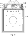
- FIG. 10 shows an enlarged view of FIG. 3 , where it can be seen that a frame 57 has a U-shape and consists essentially of two mutually parallel lifting devices 16, each of which lifting device 16 has a vertical rail 73, are mounted on the rotatably mounted rollers 25.
- the rollers 25 are based - as in the FIGS. 2 and 3 shown - on the inner sides of another U-profile, which belongs to the lifting frame 57. This is especially true of the Figures 10 and 11 refer to. There, the oppositely directed U-shaped guide rails 26 can be seen, on the inner sides of the respective roller 25 rolls.
- the rollers 25 are rotatably mounted in associated bearing blocks 64, where the bearing blocks are fixed to the stationary base frame 62.
- the base frame 62 consists essentially of the aforementioned vertical rails 73, which are arranged at a mutual distance and parallel to each other fixed on the bottom-side level 75.
- the lifting frame 57 consists of a vertical plate 62, in which a series of retaining holes 65 is arranged.
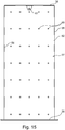
- the vertical plate 62 has rearwardly directed bends, which act as folding plates 58 in FIG FIG. 15 are shown.
- the upper, vertically folded plate is referred to as a lifting plate 56 which receives an upper support bearing 54, on which the upper part of the lifting cylinder 17 is supported.
- the lower part of the lifting cylinder 17 is supported in a bottom-side support bearing 61 according to FIG. 10 from, wherein this support bearing 61 is disposed on the bottom-side support plate 28.
- the recess 53 is disposed in the region of a foundation plate 15 and may have any depth.
- FIG. 12 is shown that the terminal 5 can be raised to the position 5 ', namely the stroke 70, so that a continuous adjustment to the operating situation is possible, as in the above description with reference to FIG FIGS. 1 to 9 has been described in detail.
- a further stroke 71 is provided, which adds to the stroke 70 and which allows that already arranged in the lower position support plate 28 of the lifting frame 57 now can be moved to the stroke 71 either partially or completely to the lower level of the bottom 61 in the recess 53 further.
- the stroke 71 is shown only shortened. In reality, it may be formed so deep that the entire terminal 5, 30 can be lowered partially or completely below the level 75 (+/- 0) into the foundation plate 15.
- the base frame 72 is according to FIG. 10 housed in a bottom-tight cover housing 55 to protect the entire lifting device 16 against the effects of dirt and damage.
- the cover 55 is fixed to the ground, because a retractability of the fixed, the base frame 72 enclosing cover 55 is not necessary because there are no valuable or damage-relevant parts.
- the advantage, however, is that the terminal 5, 5 ', 30 can be completely retractable into the ground together with the lifting frame 57 in order to protect this terminal partly or completely against damage.
- FIG. 12 shows that even a possibly existing door is secured with a vertical door edge 67 against opening or breaking when the terminal 5 is only partially retracted into the bottom recess 53.
- the lower, horizontal door edge 68 can not be opened, because it has already sunk into the region of the bottom-side recess 53 and would strike there against the inner walls in the event of an arbitrary opening.
- the lifting frame 57 consists of two folds in the region of the lifting device 16, namely from the two mutually parallel vertical plates 62a and 62b.
- FIG. 15 shows that with the arrangement of different retaining holes 65 in the region of the vertical plate 62 of the lifting frame 57, it is possible to attach a terminal 30 of any design and dimensions at any height on this vertical plate 62, resulting in a large installation freedom.
- FIG. 16 schematically shows the retractability of the lifting frame 57 in the bottom-side recess 53 in the direction of arrow 66. Only for graphic reasons, the recess 53 is only partially shown. It can either be provided at this depth to ensure that both the vertical door edge 67 at least partially enters the recess 53 and in any case the horizontal door edge 68 of the terminal 30 so as to protect the door against forced opening ,
- FIG. 17 schematically shows the interaction of the stationary base frame 72 with the lifting frame 57 guided there displaceably.
- the invention also relates to a method which, in a preferred embodiment, provides for the operation of a terminal 3, 30, 50 which is designed to be at least height-adjustable as a function of the position of the driver's seat 13 and / or the position of the driver the terminal 5, 30, 50 is driven out of a bottom-side recess 53 upon detection of an approaching motor vehicle.
- the terminal is optimally protected against vandalism and attempts to break-up during rest periods.
- terminal 5, 30, 50 is retracted at least partially or completely into the base-side recess 53 when a departing motor vehicle is detected.
- an at least two-stage lifting movement of the terminal is provided.
- This is extended only by a small amount from the bottom recess 53 to assume a standby position, but not the risk that vehicle parts (eg the bumper) with the terminal 5, 30, 50 collide. Only when the risk of collision no longer exists, the terminal 5, 30, 50 is fully extended and in a user-friendly Position brought towards the driver's door.
- the terminal may be driven to achieve the easy-to-use position, preferably in the vertical direction.
- the invention is not limited thereto. In other embodiments, a pivoting curve or a curved curve may be provided for the movement drive of the terminal.
- the device according to the invention for all automatic or. Operating terminal manufacturer is applicable.
- FIG. 18 shows a complete sinking of a terminal 5 in a bottom-side recess 53, wherein the lifting drive 17, 32 is shown only schematically. It is merely indicated that the lifting drive 17.32 may be arranged at the bottom of the recess 53. In another embodiment, not shown, however, it may be arranged on the side walls of the recess, in which case the terminal in the manner of a rail guide in the interior of the recess 53 is arranged raised and lowered.
- FIG. 19 is another sunken variant of the terminal 5 is shown, which is that the terminal 5 is not standing - as shown in the preceding figures - is sunk, but is pivoted from a stationary to a lying position.
- a pivot axis 77 is arranged on a horizontal edge of the recess 53, which is connected to the foot side of the terminal housing. With a pivot drive, not shown, thus the terminal 5 can be pivoted into a lying position in the recess 53 in or swung out in the direction of arrow 78 in a standing position.
- a sliding cover 76 which closes and opens the opening of the recess 53 in the direction of the road surface 38.
- a sliding cover 76 and a hinged lid can be used.
Landscapes
- Engineering & Computer Science (AREA)
- Business, Economics & Management (AREA)
- Transportation (AREA)
- Chemical & Material Sciences (AREA)
- General Physics & Mathematics (AREA)
- Physics & Mathematics (AREA)
- Mechanical Engineering (AREA)
- Combustion & Propulsion (AREA)
- Finance (AREA)
- Accounting & Taxation (AREA)
- Automation & Control Theory (AREA)
- Theoretical Computer Science (AREA)
- General Business, Economics & Management (AREA)
- Strategic Management (AREA)
- Power-Operated Mechanisms For Wings (AREA)
- Seats For Vehicles (AREA)
Applications Claiming Priority (1)
| Application Number | Priority Date | Filing Date | Title |
|---|---|---|---|
| DE102018111388.9A DE102018111388A1 (de) | 2018-05-14 | 2018-05-14 | Von einem Kraftfahrzeug aus betätigbares Terminal |
Publications (1)
| Publication Number | Publication Date |
|---|---|
| EP3570254A1 true EP3570254A1 (fr) | 2019-11-20 |
Family
ID=65904164
Family Applications (1)
| Application Number | Title | Priority Date | Filing Date |
|---|---|---|---|
| EP19164269.3A Withdrawn EP3570254A1 (fr) | 2018-05-14 | 2019-03-21 | Borne actionnable dans un véhicule automobile pourvue de protection contre le contre le vol |
Country Status (2)
| Country | Link |
|---|---|
| EP (1) | EP3570254A1 (fr) |
| DE (1) | DE102018111388A1 (fr) |
Families Citing this family (2)
| Publication number | Priority date | Publication date | Assignee | Title |
|---|---|---|---|---|
| DE102020216509A1 (de) | 2020-12-22 | 2022-06-23 | Gregor Pasch | Parkscheinautomat, Verfahren zum Betreiben eines solchen Parkscheinautomaten sowie dessen Verwendung zur Bewirtschaftung einer Parkplatzfläche |
| CN113048343A (zh) * | 2021-03-24 | 2021-06-29 | 兰州大学 | 一种荒漠区红外相机安装架及安装方法 |
Citations (3)
| Publication number | Priority date | Publication date | Assignee | Title |
|---|---|---|---|---|
| WO1990014991A2 (fr) * | 1989-05-26 | 1990-12-13 | Nunzio's Pizza, Incorporated | Appareil et procede de preparation et d'acheminement de repas |
| DE102013012771A1 (de) * | 2013-07-31 | 2014-02-27 | Daimler Ag | Vorrichtung und Verfahren zur Steuerung des Zugangs zu einem zugangsbeschränkten Bereich |
| DE202015002295U1 (de) * | 2015-03-26 | 2015-05-18 | Magnetic Autocontrol Gmbh | Vorrichtung für die Zufahrts- und/oder Durchfahrtskontrolle von Fahrzeugen |
-
2018
- 2018-05-14 DE DE102018111388.9A patent/DE102018111388A1/de active Pending
-
2019
- 2019-03-21 EP EP19164269.3A patent/EP3570254A1/fr not_active Withdrawn
Patent Citations (3)
| Publication number | Priority date | Publication date | Assignee | Title |
|---|---|---|---|---|
| WO1990014991A2 (fr) * | 1989-05-26 | 1990-12-13 | Nunzio's Pizza, Incorporated | Appareil et procede de preparation et d'acheminement de repas |
| DE102013012771A1 (de) * | 2013-07-31 | 2014-02-27 | Daimler Ag | Vorrichtung und Verfahren zur Steuerung des Zugangs zu einem zugangsbeschränkten Bereich |
| DE202015002295U1 (de) * | 2015-03-26 | 2015-05-18 | Magnetic Autocontrol Gmbh | Vorrichtung für die Zufahrts- und/oder Durchfahrtskontrolle von Fahrzeugen |
Also Published As
| Publication number | Publication date |
|---|---|
| DE102018111388A1 (de) | 2019-11-14 |
Similar Documents
| Publication | Publication Date | Title |
|---|---|---|
| EP3007953B1 (fr) | Paroi de protection pour la protection de personnes de véhicules ferroviaires en circulation | |
| EP3489416B1 (fr) | Machine de traitement du sol avec un dispositif deployable et retractable associant pare-brise et toit protecteur et procédé pour modifier la hauteur de cette machine de traitement du sol | |
| DE102009001975A1 (de) | System zur Verringerung des Luftwiderstandes eines Lastkraftwagens | |
| DE10254035B4 (de) | Lastkraftwagen | |
| DE60033129T2 (de) | Abnehmbares dachmodul für einen kraftfahrzeug-fahrgastraum und mit solchem modul ausgerüstetes kraftfahrzeug | |
| EP3570254A1 (fr) | Borne actionnable dans un véhicule automobile pourvue de protection contre le contre le vol | |
| DE19731324A1 (de) | Ausziehbarer Ladeboden für ein Fahrzeug | |
| DE102020130653A1 (de) | Mobile Arbeitsmaschine mit einem höhenverstellbaren Fahrerschutzdach | |
| DE102017011996B3 (de) | Kraftwagen mit einem über eine Türöffnung zugänglichen Innenraum | |
| DE102012014448A1 (de) | Nutzfahrzeug mit Bilderfassungseinrichtung | |
| AT509870A4 (de) | Anordnung zum fahrtrichtungsorientierten ausrichten von mehrspurigen kraftfahrzeugen auf parkplätzen bzw. in garagen | |
| DE202017106023U1 (de) | Zusammenklappbare Abdeckung für ein Fenster oder eine Tür eines Fahrzeugs | |
| EP2862550B1 (fr) | Autocar doté d'un dispositif de levage en tant qu'aide à la montée pour personne en fauteuil roulant | |
| DE102014003909B4 (de) | Kraftfahrzeug | |
| DE19635751C1 (de) | Fahrerkabine für Erdbaumaschinen | |
| DE10159300B4 (de) | Vorrichtung zum Verhindern von Karosserieschäden an einem Fahrzeug | |
| DE102007041633B3 (de) | Kraftfahrzeug mit seitlicher Beladeeinrichtung | |
| EP4112375B1 (fr) | Véhicule automobile, en particulier caravane automobile | |
| DE202007014308U1 (de) | Kraftfahrzeug mit seitlicher Beladeeinrichtung | |
| EP2077200B1 (fr) | Véhicule particulier et dispositif pare-vent | |
| DE3830691C2 (fr) | ||
| DE202017100651U1 (de) | Vorrichtung zur Aufnahme von Gegenständen | |
| EP1002760A1 (fr) | Cabine pour chariot de manutention à siège frontale | |
| DE202021004351U1 (de) | Garagenhubsystem | |
| WO2016078943A1 (fr) | Zone d'une gare comprenant une paroi de protection pouvant être enfoncée pour la protection de personnes contre des véhicules ferroviaires qui roulent |
Legal Events
| Date | Code | Title | Description |
|---|---|---|---|
| PUAI | Public reference made under article 153(3) epc to a published international application that has entered the european phase |
Free format text: ORIGINAL CODE: 0009012 |
|
| STAA | Information on the status of an ep patent application or granted ep patent |
Free format text: STATUS: THE APPLICATION HAS BEEN PUBLISHED |
|
| AK | Designated contracting states |
Kind code of ref document: A1 Designated state(s): AL AT BE BG CH CY CZ DE DK EE ES FI FR GB GR HR HU IE IS IT LI LT LU LV MC MK MT NL NO PL PT RO RS SE SI SK SM TR |
|
| AX | Request for extension of the european patent |
Extension state: BA ME |
|
| STAA | Information on the status of an ep patent application or granted ep patent |
Free format text: STATUS: THE APPLICATION IS DEEMED TO BE WITHDRAWN |
|
| 18D | Application deemed to be withdrawn |
Effective date: 20200603 |