EP2724973B1 - Grue - Google Patents
Grue Download PDFInfo
- Publication number
- EP2724973B1 EP2724973B1 EP13005030.5A EP13005030A EP2724973B1 EP 2724973 B1 EP2724973 B1 EP 2724973B1 EP 13005030 A EP13005030 A EP 13005030A EP 2724973 B1 EP2724973 B1 EP 2724973B1
- Authority
- EP
- European Patent Office
- Prior art keywords
- crane
- tower
- access
- lift
- ladder
- Prior art date
- Legal status (The legal status is an assumption and is not a legal conclusion. Google has not performed a legal analysis and makes no representation as to the accuracy of the status listed.)
- Active
Links
- 210000000078 claw Anatomy 0.000 claims description 3
- 230000005540 biological transmission Effects 0.000 claims 1
- 238000009434 installation Methods 0.000 description 6
- 230000033001 locomotion Effects 0.000 description 5
- 238000010276 construction Methods 0.000 description 3
- 238000004519 manufacturing process Methods 0.000 description 3
- 230000007246 mechanism Effects 0.000 description 3
- 238000009420 retrofitting Methods 0.000 description 3
- 239000004020 conductor Substances 0.000 description 2
- 238000012544 monitoring process Methods 0.000 description 2
- 238000013459 approach Methods 0.000 description 1
- 230000008859 change Effects 0.000 description 1
- 230000009849 deactivation Effects 0.000 description 1
- 230000003111 delayed effect Effects 0.000 description 1
- 230000001419 dependent effect Effects 0.000 description 1
- 238000006073 displacement reaction Methods 0.000 description 1
- 230000000694 effects Effects 0.000 description 1
- 238000005516 engineering process Methods 0.000 description 1
- 238000011156 evaluation Methods 0.000 description 1
- 230000010354 integration Effects 0.000 description 1
- 230000004807 localization Effects 0.000 description 1
- 230000008092 positive effect Effects 0.000 description 1
- 230000007420 reactivation Effects 0.000 description 1
- 230000007704 transition Effects 0.000 description 1
Images

Classifications
-
- B—PERFORMING OPERATIONS; TRANSPORTING
- B66—HOISTING; LIFTING; HAULING
- B66B—ELEVATORS; ESCALATORS OR MOVING WALKWAYS
- B66B9/00—Kinds or types of lifts in, or associated with, buildings or other structures
-
- B—PERFORMING OPERATIONS; TRANSPORTING
- B66—HOISTING; LIFTING; HAULING
- B66C—CRANES; LOAD-ENGAGING ELEMENTS OR DEVICES FOR CRANES, CAPSTANS, WINCHES, OR TACKLES
- B66C13/00—Other constructional features or details
- B66C13/52—Details of compartments for driving engines or motors or of operator's stands or cabins
- B66C13/54—Operator's stands or cabins
-
- B—PERFORMING OPERATIONS; TRANSPORTING
- B66—HOISTING; LIFTING; HAULING
- B66C—CRANES; LOAD-ENGAGING ELEMENTS OR DEVICES FOR CRANES, CAPSTANS, WINCHES, OR TACKLES
- B66C15/00—Safety gear
-
- B—PERFORMING OPERATIONS; TRANSPORTING
- B66—HOISTING; LIFTING; HAULING
- B66C—CRANES; LOAD-ENGAGING ELEMENTS OR DEVICES FOR CRANES, CAPSTANS, WINCHES, OR TACKLES
- B66C23/00—Cranes comprising essentially a beam, boom, or triangular structure acting as a cantilever and mounted for translatory of swinging movements in vertical or horizontal planes or a combination of such movements, e.g. jib-cranes, derricks, tower cranes
- B66C23/18—Cranes comprising essentially a beam, boom, or triangular structure acting as a cantilever and mounted for translatory of swinging movements in vertical or horizontal planes or a combination of such movements, e.g. jib-cranes, derricks, tower cranes specially adapted for use in particular purposes
- B66C23/26—Cranes comprising essentially a beam, boom, or triangular structure acting as a cantilever and mounted for translatory of swinging movements in vertical or horizontal planes or a combination of such movements, e.g. jib-cranes, derricks, tower cranes specially adapted for use in particular purposes for use on building sites; constructed, e.g. with separable parts, to facilitate rapid assembly or dismantling, for operation at successively higher levels, for transport by road or rail
-
- B—PERFORMING OPERATIONS; TRANSPORTING
- B66—HOISTING; LIFTING; HAULING
- B66C—CRANES; LOAD-ENGAGING ELEMENTS OR DEVICES FOR CRANES, CAPSTANS, WINCHES, OR TACKLES
- B66C23/00—Cranes comprising essentially a beam, boom, or triangular structure acting as a cantilever and mounted for translatory of swinging movements in vertical or horizontal planes or a combination of such movements, e.g. jib-cranes, derricks, tower cranes
- B66C23/62—Constructional features or details
Definitions
- the invention relates to a tower crane, in particular a tower crane, with at least one crane cab and at least one crane driver lift.
- Tower cranes with a fixed tower have so far been equipped with crane operator lifts in individual cases in order to make the ascent to the crane cabin more comfortable, especially in the case of large tower heights.
- Only a few countries have issued legal requirements for the installation of a crane operator lift.
- this will change in the near future, so with a rise of 60 m or less, the installation of a lift is required by law.
- Previous solutions suggest that outside the crane tower cross-section commercial elevators are grown, which are held in position via rails or cable guides and movable by rack drives or winch drives in height.
- a tower crane according to the preamble of claim 1 is known from FR 2 936 236 A1 known.
- Object of the present invention is to develop a tower crane of the type mentioned, so that it is simplified in terms of structure and optimized in terms of space requirements.
- a tower crane in particular a tower crane, proposed, which has at least one crane cab and at least one crane driver lift.
- the invention provides that the at least one crane operator lift is arranged within the crane tower cross section.
- An arrangement of the crane operator lift within the crane tower cross-section means that at least a majority of the elevator components within the crane tower cross section at the individual crane components, in particular grid elements, is fixed. Above all, the elevator car is moved vertically in the interior of the crane tower cross section.
- the inventive arrangement of the crane operator lift the original crane tower cross section can be maintained. This not only has a positive effect on the construction site, but also brings with it certain advantages during transport and when setting up the crane.
- the crane cab itself can be open or closed.
- the lower entry of the crane operator lift is provided in the region of the lowest lattice piece.
- the upper entry is arranged in contrast in the area of at least one crane cab.
- the guide rails can be designed simply or in pairs with a parallel track.
- the guide rails are preferably designed in several parts, wherein a rail segment is particularly preferably provided per lattice piece.
- the guide rails are firmly mounted on the crane and remain at the crane tower during crane transport. Accordingly, the assembly of the guidance system takes place once during crane production or when retrofitting existing cranes with the elevator system according to the invention.
- the elevator drive comprises a cable drive.
- the cable drive is tolerant especially at offset points within the guide rail.
- the drive of the crane operator lift may have a rack and pinion drive.
- Rack drives require a precise mounting of the guide rails. A possible misalignment in the rail system must be corrected at great expense by readjustment following the installation of the crane tower.
- this has one or more receptacles on the individual tower elements, which lie within the crane tower cross-section and allow a detachable attachment of the crane operator lift.
- the recordings can be designed as claws or similar fastening means.
- the receiving means, in particular claws can be retrofitted to the individual crane elements, in particular lattice pieces, mounted and therefore allow a simple and straightforward retrofitting of existing cranes with a crane driver lift.
- a crane ladder is provided, through which the crane operator can access the crane cab in a conventional manner.
- the crane ascent runs in a known manner within the crane tower cross-section and allows by single ladder elements the climb to the crane cab.
- One possible safety measure involves the installation of one or more mechanical screens in the area of the crane ascent, which block and at best prevent access to the crane lift system.
- individual grids are available, which are to be arranged in the region of the intermediate platforms of each tower piece.
- the shielding elements provide an additional wind attack surface, which in turn can have a negative effect on the calculated stability of the crane.
- the maximum construction height of the crane must be reduced or the effort to ensure stability increases noticeably. This can affect the required amount of ballast or the technical design of the crane foundation.
- an access control system is installed to control access to at least one crane access. Up to now, unauthorized persons could easily ascend at least to the crane cabin, since the access to the tower was neither locked nor otherwise secured.
- the integration of the access control system allows monitoring of the crane operator lift and / or crane ascent at the lower entrance. For example, unauthorized persons can be denied access to the crane system, in particular the crane cab.
- the control system or the crane control associated with the control system acquires knowledge of the number of persons who are in the crane driver's hoist or in the crane ascent. This can ensure that authorized persons leave the crane ascent or crane lift in a timely manner and do not remain permanently in it.
- motion detectors can be used, by means of which the access control and / or the monitoring of the security area or traversing area of the elevator are monitored.
- an authorized person receives access to the crane ascent or to the crane operator lift, which must first be authenticated by means of an access key.
- An electronic key is any type of chip or card that stores electronic data that is readable by the access control. After evaluation of the data, the access control can either release or block the access.
- Access to the crane access or to the crane lift can be secured via one or more access doors. If the access control system grants access to the crane access for an authorized person, these doors are unlocked or automatically opened. It makes sense to arrange at least one door at the lower entrance area. Ideally, at least one additional door is arranged at the upper entrance.
- a controller which controls the drive of the crane operator lift as a function of the access control of the at least one crane ladder.
- a suitable control of the crane lift can take place, as a result of which the risk to these persons due to the elevator movement can be minimized or completely eliminated as far as possible.
- the energy supply of the crane operator lift is deactivated as soon as access to the crane access is enabled.
- the deactivation of the crane lift can be delayed, provided that the elevator car is located between the lower and upper breakpoint. As a result, the cabin can still be moved to a defined breakpoint. It makes more sense to release the access to the crane access only if the elevator car is at one of the stops and is not moved. After the release, an immediate interruption of the power supply can take place.
- a reactivation of the power supply by the controller is preferably then as soon as access to the crane access is blocked. Locking the crane access is possible as soon as it is ensured that there are no persons in the area of the crane ascent.
- an access control takes place when a person enters the crane ascent, whereby the exit from the crane ascent is additionally checked. As a result, the controller obtains knowledge about whether the people in the crane climb have left this again.
- the access control system may include one or more reading units suitable for wireless reception of electronic key data.
- the entry of an electronic key into the reception area of one of the reading units may be sufficient to release access to the crane access.
- the reading units or the electronic key can be designed in accordance with an RFID system, wherein when the electronic key approaches one of the reading units, it is excited to transmit information to the reading unit.
- RFID technology can also an LWID system (according to the IEEE standard), which is also called RuBee.
- the reading units are arranged distributed over the ascent path, so that the distance traveled by the person or the electronic key is comprehensible. This makes it easier to check whether the respective person or the electronic key has entered or left the crane access. Ideally, this can also be a concrete localization of authorized persons. The exact position data can then be taken into account by the controller for the elevator control. In this case, it would be sufficient to limit the travel of the elevator. Unless the travel of the elevator crosses the localized position of the authorized person, the elevator operation can be maintained.
- the power supply of the crane lift is deactivated as soon as at least one electronic key is recognized by one of the reading units within the crane climb.
- the access control system is designed to provide either access to the elevator system or, alternatively, crane access.
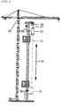
- FIG. 1 shows a cross section through a single grid element 10 of the tower crane according to the invention.
- the entire tower crane has a conventional tower access 20, which consists of individual conductor elements 21.
- the crane operator can therefore enter into the cavity of the lowermost grid element and by means of the conductor arrangement 21 up to the crane cabin 40 (FIG. FIG. 2 ) reach.
- the space requirement of the crane ascent occupies about two-thirds of the crane tower cross-sectional area.
- the arrow 22 indicates the ascent by the lattice pieces 10th
- a crane operator lift 30 is arranged according to the invention, which is available in addition to the conventional crane ladder 20.
- the elevator shaft runs in the drawing plane right below grid piece corner shown and takes about half of the remaining cross-sectional area.
- the cabin 31 of the crane operator lift 30 slides from the tower base 50 all the way to the crane cabin 40 in the vertical direction ( FIG. 2 ).
- As guide means two guide rails 60 are provided, which run parallel to each other in the vertical direction from the tower base 50 to the crane cab 31 on the inside of the lattice pieces.
- the cabin 31 itself is at least partially closed. The entry takes place via a mechanical door mechanism 32. To open the access door 32, it is displaced in the direction of the arrow 33 inwards into the cabin 31.
- Other opening mechanisms are of course possible and encompassed by the invention.
- the winch 70 is provided ( FIG. 2 ), the elevator rope 71 runs from the elevator car 31 to the top of the tower and is wound up or unwound by the winch 70.
- the winch can be arranged in a manner not shown here on the roof of the elevator car.
- an offset between the adjacent guide elements of the guide rails 60 can occur when setting up the individual lattice pieces, in particular both in the vertical and in the horizontal direction.
- the engagement of the guide means of the cab 31 in the guide rails 60 allows a certain amount of play. In combination with the cable drive, it is possible to easily pass over any offset points between adjacent guide elements.
- an access control system is installed in order to avoid any danger to the persons in the crane access 20 by the elevator car 31.
- FIG. 1a can be seen, access to the crane access 20 can be locked or released via a door assembly 80.
- the mechanical folding movement of the door 80 can be either automated or manual.
- a door lock mechanism for locking and unlocking the door 80 is addressed electronically by the access control system.
- the illustrated door 80 is arranged in the vicinity of the crane foot in the entrance area of the crane ladder 20. At the same time, another door element 80, which blocks or releases access to the crane ascent or descent, is also located in the spire.
- the door 80 is therefore arranged in a vertical direction above the access 90 to the elevator system 30.
- the crane operator gets access to the crane ladder 20 by means of a mechanical key. If the door 80 is opened, the crane control automatically blocks the power supply to the elevator system 30 so that elevator operation during the released crane climb 20 is prevented.
- a key in a glazed box is accessible on both doors 80.
- the access 90, 100 to the elevator 30 may also be keyed.
- one or more reading units for RFID chips may be installed on each door 80.
- the electronic key data of the chip can be read out and the release of the doors 80 can be issued.
- the access 90, 100 to the cabin which can also be controlled by means of reading units.
- the power supply for the crane operator lift 30 is interrupted as soon as one of the doors 80 is opened or unlocked.
- the electronic access control detects the actual passage of the door 80 by the person based on the chip movement.
Landscapes
- Engineering & Computer Science (AREA)
- Mechanical Engineering (AREA)
- Structural Engineering (AREA)
- Automation & Control Theory (AREA)
- Transportation (AREA)
- Types And Forms Of Lifts (AREA)
Claims (12)
- Grue à tour, plus particulièrement grue à tour rotative, avec au moins une cabine de grue (40), au moins une échelle de grue (20) et au moins un ascenseur pour grutier (30), l'au moins un ascenseur pour grutier (30) étant disposé à l'intérieur de la section de la tour de la grue, l'accès à au moins une échelle de grue (20) et/ou à au moins un ascenseur pour grutier (30) étant sécurisé par un système de contrôle d'accès, caractérisée en ce qu'un dispositif de commande est prévu, qui commande, en fonction du système de contrôle d'accès d'au moins une échelle de grue (20), l'entraînement de l'ascenseur pour grutier (30).
- Grue à tour selon la revendication 1, caractérisée en ce qu'un ou plusieurs rails de guidage (60) sont disposés, pour le guidage de l'au moins un ascenseur pour grutier (30), à l'intérieur de la section de la tour de la grue.
- Grue à tour selon la revendication 2, caractérisée en ce que des moyens de guidage du côté de l'ascenseur et des rails de guidage (60) du côté de la grue s'emboîtent entre eux avec un jeu déterminé, afin de compenser les endroits de décalage ou les irrégularités des rails de guidage (60).
- Grue à tour selon l'une des revendications précédentes, caractérisée en ce que l'au moins un ascenseur pour grutier (30) comprend un dispositif d'entraînement à câble.
- Grue à tour selon l'une des revendications précédentes, caractérisée en ce que l'ascenseur pour grutier (30) comprend un dispositif d'entraînement à crémaillère.
- Grue à tour selon l'une des revendications précédentes, caractérisée en ce qu'un ou plusieurs logements, plus particulièrement des griffes ou autres, sont prévus dans la section de la tour de grue des différents éléments de la tour, qui permettent une fixation amovible de l'ascenseur pour grutier (30) à l'intérieur de la section de la tour de grue.
- Grue à tour selon la revendication 1, caractérisée en ce qu'au moins une échelle de grue (20) est sécurisée par une ou plusieurs portes d'accès (80), plus particulièrement par une porte d'accès (80) au niveau de l'entrée inférieure et de l'entrée supérieure de la grue.
- Grue à tour selon la revendication 1, caractérisée en ce que le dispositif de commande est conçu de façon à ce que celui-ci désactive l'alimentation en énergie de l'ascenseur pour grutier (30) dès que l'accès à l'échelle de la grue (20) est autorisé.
- Grue à tour selon la revendication 1 ou 8, caractérisée en ce que le dispositif de commande est conçu de façon à ce que celui-ci active l'alimentation en énergie de l'ascenseur pour grutier (30) dès que l'accès à l'échelle de la grue (20) est bloqué.
- Grue à tour selon l'une des revendications 1 à 9, caractérisée en ce que le contrôle d'accès peut être actionné ou bien autorisé ou bloqué au moyen d'une clé mécanique et/ou électronique.
- Grue à tour selon l'une des revendications 1 à 10, caractérisée en ce que le contrôle d'accès comprend une ou plusieurs unités de lecture pour la réception sans fil de données de clés électroniques, plus particulièrement sur la base du système RFID, un système LWID ou un système de transmission par radio similaire, de préférence une réception étant assurée sur toute la longueur de l'échelle.
- Grue à tour selon l'une des revendications 7 à 11, caractérisée en ce que le contrôle d'accès est conçu de façon à ce que l'accès soit autorisé sélectivement au système d'ascenseur ou à l'échelle de la grue.
Applications Claiming Priority (1)
| Application Number | Priority Date | Filing Date | Title |
|---|---|---|---|
| DE102012020819.7A DE102012020819A1 (de) | 2012-10-23 | 2012-10-23 | Kran |
Publications (2)
| Publication Number | Publication Date |
|---|---|
| EP2724973A1 EP2724973A1 (fr) | 2014-04-30 |
| EP2724973B1 true EP2724973B1 (fr) | 2018-04-25 |
Family
ID=49484068
Family Applications (1)
| Application Number | Title | Priority Date | Filing Date |
|---|---|---|---|
| EP13005030.5A Active EP2724973B1 (fr) | 2012-10-23 | 2013-10-21 | Grue |
Country Status (4)
| Country | Link |
|---|---|
| US (1) | US9809422B2 (fr) |
| EP (1) | EP2724973B1 (fr) |
| DE (1) | DE102012020819A1 (fr) |
| ES (1) | ES2680652T3 (fr) |
Cited By (1)
| Publication number | Priority date | Publication date | Assignee | Title |
|---|---|---|---|---|
| DE102018009464A1 (de) | 2018-12-04 | 2020-06-04 | Geda-Dechentreiter Gmbh & Co. Kg | Mast, insbesondere Kranmast für einen Turmdrehkran |
Families Citing this family (8)
| Publication number | Priority date | Publication date | Assignee | Title |
|---|---|---|---|---|
| DE102015107560A1 (de) | 2015-05-13 | 2016-11-17 | USound GmbH | Schallwandleranordnung mit MEMS-Schallwandler |
| CN104973515B (zh) * | 2015-07-05 | 2017-03-08 | 范志甫 | 一种起重机多节安全操作室及其操作方法 |
| CN105271003A (zh) * | 2015-10-28 | 2016-01-27 | 林蓉瑶 | 一种操作方便的塔式起重机 |
| CN106285041A (zh) * | 2016-08-16 | 2017-01-04 | 中国建筑第二工程局有限公司 | 一种塔机反向降塔方法 |
| TWI650282B (zh) * | 2017-06-02 | 2019-02-11 | 國立高雄科技大學 | 安全偵測系統 |
| DE202018101551U1 (de) | 2018-03-20 | 2019-06-25 | Geda-Dechentreiter Gmbh & Co. Kg | Übertritt für einen Aufzug |
| US11964850B2 (en) * | 2019-03-20 | 2024-04-23 | Liebherr-Werk Biberach Gmbh | Crane |
| CN112324793B (zh) * | 2020-11-20 | 2021-12-24 | 安徽博微长安电子有限公司 | 一种伸缩式抗风拉杆机构 |
Family Cites Families (14)
| Publication number | Priority date | Publication date | Assignee | Title |
|---|---|---|---|---|
| US3080981A (en) * | 1961-06-06 | 1963-03-12 | Schwermaschb Kirow Veb | Tower-crane cabin |
| US3627079A (en) * | 1969-10-31 | 1971-12-14 | Norse Dev Corp | Elevator system for mine shaft |
| US3677370A (en) * | 1970-08-19 | 1972-07-18 | Security Systems Inc | Elevator alarm system |
| SE457168B (sv) * | 1985-12-03 | 1988-12-05 | Leif Uno Aake Loftmyr | Anordning vid arbetshytter foer kranar |
| FR2675196B1 (fr) * | 1991-04-12 | 1998-09-04 | Hek France | Echelle de secours avec ascenseur incorpore. |
| DE9107493U1 (de) * | 1991-06-18 | 1992-02-06 | Anton, Rudolf, 7910 Neu-Ulm | Turmdrehkran - Kranführeraufzug mit Fahrkorb |
| FI112068B (fi) * | 1992-12-22 | 2003-10-31 | Kone Corp | Kauko-ohjainliityntä hissijärjestelmään |
| NL1010908C2 (nl) * | 1998-12-28 | 2000-06-30 | Altrex Bv | Liftkooigeleidingsstelsel. |
| DE10025074B4 (de) * | 2000-05-20 | 2006-11-09 | Hailo-Werk Rudolf Loh Gmbh & Co. Kg | Einrichtung zum Befördern von Personen |
| NL1017257C2 (nl) * | 2001-02-01 | 2002-08-02 | Slechtvalk Holding B V | Hijskraan. |
| FI118045B (fi) * | 2005-08-31 | 2007-06-15 | Kone Corp | Menetelmä ja kutsujärjestelmä |
| FR2936236A1 (fr) * | 2008-09-19 | 2010-03-26 | Jean Pierre Teso | Ascenseur d'acces aux postes de travail |
| IT1393937B1 (it) * | 2009-04-09 | 2012-05-17 | Rolic Invest Sarl | Aerogeneratore |
| PT2639193E (pt) * | 2012-03-15 | 2015-02-04 | Manitowoc Crane Group France | Dispositivo de acesso em altura para guindaste de torre |
-
2012
- 2012-10-23 DE DE102012020819.7A patent/DE102012020819A1/de not_active Ceased
-
2013
- 2013-10-21 ES ES13005030.5T patent/ES2680652T3/es active Active
- 2013-10-21 EP EP13005030.5A patent/EP2724973B1/fr active Active
- 2013-10-22 US US14/060,395 patent/US9809422B2/en active Active
Non-Patent Citations (1)
| Title |
|---|
| None * |
Cited By (2)
| Publication number | Priority date | Publication date | Assignee | Title |
|---|---|---|---|---|
| DE102018009464A1 (de) | 2018-12-04 | 2020-06-04 | Geda-Dechentreiter Gmbh & Co. Kg | Mast, insbesondere Kranmast für einen Turmdrehkran |
| EP3683178A1 (fr) | 2018-12-04 | 2020-07-22 | GEDA-Dechentreiter GmbH & Co. KG. | Mât avec ascenseur et sécurité personnelle, en particulier mât de grue pour une grue à tour |
Also Published As
| Publication number | Publication date |
|---|---|
| DE102012020819A1 (de) | 2014-05-08 |
| US20140110367A1 (en) | 2014-04-24 |
| EP2724973A1 (fr) | 2014-04-30 |
| US9809422B2 (en) | 2017-11-07 |
| ES2680652T3 (es) | 2018-09-10 |
Similar Documents
| Publication | Publication Date | Title |
|---|---|---|
| EP2724973B1 (fr) | Grue | |
| EP3007953B1 (fr) | Paroi de protection pour la protection de personnes de véhicules ferroviaires en circulation | |
| EP1930285B1 (fr) | Installation d'ascenseur dotée d'un dispositif de sécurité sur les portes d'ascenseur | |
| WO2012126619A1 (fr) | Ascenseur à hauteur de tête de gaine minimale et à espace de sécurité permanent | |
| EP3003944B1 (fr) | Verrou de porte d'une porte palière d'une installation d'ascenseur. | |
| EP2766292B1 (fr) | Ascenseur | |
| EP2727875A1 (fr) | Élévateur avec trappe d'entretien dans le sol de la cabine | |
| EP3186183B1 (fr) | Dispositif pour actionner une porte cabine et porte palière d'un ascenseur | |
| DE19712646C2 (de) | Seilaufzug | |
| DE2729381A1 (de) | Kletteraufzug | |
| DE102017004719A1 (de) | Vorrichtung für einen gesicherten Bereich in einem Aufzugschacht | |
| EP1053202B1 (fr) | Systeme de securite pour monte-charge | |
| EP2172411B1 (fr) | Installation d'ascenseur dotée d'une sécurité de porte en fonction de la position | |
| EP2730478A2 (fr) | Véhicule ferroviaire doté d'une plate-forme de levage dans la zone de montée | |
| AT517871B1 (de) | Aufzugskabine | |
| DE202011100364U1 (de) | Personen-Schutzsystem | |
| DE102011100769A1 (de) | Personen-Schutzsystem | |
| EP2050703B1 (fr) | Installation d'ascenseur pour personnes et/ou charges dotée d'au moins une cabine d'ascenseur | |
| DE29714403U1 (de) | Versorgungseinrichtung für Druckmaschinen mit einem Materiallift | |
| CH702838B1 (de) | Lift, mit geschlossener Kabine im Servicemodus fahrbar. | |
| DE102023107535A1 (de) | Shuttle-System mit einem Senkrechtförderer-Modul sowie Verfahren zum Beheben einer Störung in einem Senkrechtförderer-Modul eines Shuttle-Systems | |
| EP3683178A1 (fr) | Mât avec ascenseur et sécurité personnelle, en particulier mât de grue pour une grue à tour | |
| DE4426071A1 (de) | Bauaufzug | |
| CH704976A2 (de) | Lift ohne Liftschachtkopf oder mit minimaler Liftschacht-Kopfhöhe und mit permanentem Schutzraum. | |
| CH704628B1 (de) | Lift mit minimaler Liftschacht-Grubentiefe und mit permanentem Schutzraum. |
Legal Events
| Date | Code | Title | Description |
|---|---|---|---|
| PUAI | Public reference made under article 153(3) epc to a published international application that has entered the european phase |
Free format text: ORIGINAL CODE: 0009012 |
|
| 17P | Request for examination filed |
Effective date: 20131021 |
|
| AK | Designated contracting states |
Kind code of ref document: A1 Designated state(s): AL AT BE BG CH CY CZ DE DK EE ES FI FR GB GR HR HU IE IS IT LI LT LU LV MC MK MT NL NO PL PT RO RS SE SI SK SM TR |
|
| AX | Request for extension of the european patent |
Extension state: BA ME |
|
| 17P | Request for examination filed |
Effective date: 20141030 |
|
| RAP3 | Party data changed (applicant data changed or rights of an application transferred) |
Owner name: LIEBHERR-WERK BIBERACH GMBH |
|
| 17Q | First examination report despatched |
Effective date: 20170103 |
|
| REG | Reference to a national code |
Ref country code: DE Ref legal event code: R079 Ref document number: 502013009980 Country of ref document: DE Free format text: PREVIOUS MAIN CLASS: B66C0013540000 Ipc: B66C0023260000 |
|
| GRAP | Despatch of communication of intention to grant a patent |
Free format text: ORIGINAL CODE: EPIDOSNIGR1 |
|
| RIC1 | Information provided on ipc code assigned before grant |
Ipc: B66B 9/00 20060101ALI20171031BHEP Ipc: B66C 13/54 20060101ALI20171031BHEP Ipc: B66C 15/00 20060101ALI20171031BHEP Ipc: B66C 23/26 20060101AFI20171031BHEP |
|
| INTG | Intention to grant announced |
Effective date: 20171114 |
|
| GRAJ | Information related to disapproval of communication of intention to grant by the applicant or resumption of examination proceedings by the epo deleted |
Free format text: ORIGINAL CODE: EPIDOSDIGR1 |
|
| GRAP | Despatch of communication of intention to grant a patent |
Free format text: ORIGINAL CODE: EPIDOSNIGR1 |
|
| INTC | Intention to grant announced (deleted) | ||
| GRAA | (expected) grant |
Free format text: ORIGINAL CODE: 0009210 |
|
| GRAS | Grant fee paid |
Free format text: ORIGINAL CODE: EPIDOSNIGR3 |
|
| INTG | Intention to grant announced |
Effective date: 20180313 |
|
| AK | Designated contracting states |
Kind code of ref document: B1 Designated state(s): AL AT BE BG CH CY CZ DE DK EE ES FI FR GB GR HR HU IE IS IT LI LT LU LV MC MK MT NL NO PL PT RO RS SE SI SK SM TR |
|
| REG | Reference to a national code |
Ref country code: GB Ref legal event code: FG4D Free format text: NOT ENGLISH |
|
| REG | Reference to a national code |
Ref country code: CH Ref legal event code: EP Ref country code: CH Ref legal event code: NV Representative=s name: KELLER AND PARTNER PATENTANWAELTE AG, CH |
|
| REG | Reference to a national code |
Ref country code: AT Ref legal event code: REF Ref document number: 992651 Country of ref document: AT Kind code of ref document: T Effective date: 20180515 |
|
| REG | Reference to a national code |
Ref country code: IE Ref legal event code: FG4D Free format text: LANGUAGE OF EP DOCUMENT: GERMAN |
|
| REG | Reference to a national code |
Ref country code: DE Ref legal event code: R096 Ref document number: 502013009980 Country of ref document: DE |
|
| REG | Reference to a national code |
Ref country code: NL Ref legal event code: MP Effective date: 20180425 |
|
| REG | Reference to a national code |
Ref country code: ES Ref legal event code: FG2A Ref document number: 2680652 Country of ref document: ES Kind code of ref document: T3 Effective date: 20180910 Ref country code: LT Ref legal event code: MG4D |
|
| PG25 | Lapsed in a contracting state [announced via postgrant information from national office to epo] |
Ref country code: NL Free format text: LAPSE BECAUSE OF FAILURE TO SUBMIT A TRANSLATION OF THE DESCRIPTION OR TO PAY THE FEE WITHIN THE PRESCRIBED TIME-LIMIT Effective date: 20180425 |
|
| REG | Reference to a national code |
Ref country code: FR Ref legal event code: PLFP Year of fee payment: 6 |
|
| PG25 | Lapsed in a contracting state [announced via postgrant information from national office to epo] |
Ref country code: BG Free format text: LAPSE BECAUSE OF FAILURE TO SUBMIT A TRANSLATION OF THE DESCRIPTION OR TO PAY THE FEE WITHIN THE PRESCRIBED TIME-LIMIT Effective date: 20180725 Ref country code: FI Free format text: LAPSE BECAUSE OF FAILURE TO SUBMIT A TRANSLATION OF THE DESCRIPTION OR TO PAY THE FEE WITHIN THE PRESCRIBED TIME-LIMIT Effective date: 20180425 Ref country code: SE Free format text: LAPSE BECAUSE OF FAILURE TO SUBMIT A TRANSLATION OF THE DESCRIPTION OR TO PAY THE FEE WITHIN THE PRESCRIBED TIME-LIMIT Effective date: 20180425 Ref country code: NO Free format text: LAPSE BECAUSE OF FAILURE TO SUBMIT A TRANSLATION OF THE DESCRIPTION OR TO PAY THE FEE WITHIN THE PRESCRIBED TIME-LIMIT Effective date: 20180725 Ref country code: PL Free format text: LAPSE BECAUSE OF FAILURE TO SUBMIT A TRANSLATION OF THE DESCRIPTION OR TO PAY THE FEE WITHIN THE PRESCRIBED TIME-LIMIT Effective date: 20180425 Ref country code: LT Free format text: LAPSE BECAUSE OF FAILURE TO SUBMIT A TRANSLATION OF THE DESCRIPTION OR TO PAY THE FEE WITHIN THE PRESCRIBED TIME-LIMIT Effective date: 20180425 |
|
| PG25 | Lapsed in a contracting state [announced via postgrant information from national office to epo] |
Ref country code: HR Free format text: LAPSE BECAUSE OF FAILURE TO SUBMIT A TRANSLATION OF THE DESCRIPTION OR TO PAY THE FEE WITHIN THE PRESCRIBED TIME-LIMIT Effective date: 20180425 Ref country code: RS Free format text: LAPSE BECAUSE OF FAILURE TO SUBMIT A TRANSLATION OF THE DESCRIPTION OR TO PAY THE FEE WITHIN THE PRESCRIBED TIME-LIMIT Effective date: 20180425 Ref country code: GR Free format text: LAPSE BECAUSE OF FAILURE TO SUBMIT A TRANSLATION OF THE DESCRIPTION OR TO PAY THE FEE WITHIN THE PRESCRIBED TIME-LIMIT Effective date: 20180726 Ref country code: LV Free format text: LAPSE BECAUSE OF FAILURE TO SUBMIT A TRANSLATION OF THE DESCRIPTION OR TO PAY THE FEE WITHIN THE PRESCRIBED TIME-LIMIT Effective date: 20180425 |
|
| PG25 | Lapsed in a contracting state [announced via postgrant information from national office to epo] |
Ref country code: PT Free format text: LAPSE BECAUSE OF FAILURE TO SUBMIT A TRANSLATION OF THE DESCRIPTION OR TO PAY THE FEE WITHIN THE PRESCRIBED TIME-LIMIT Effective date: 20180827 |
|
| REG | Reference to a national code |
Ref country code: DE Ref legal event code: R097 Ref document number: 502013009980 Country of ref document: DE |
|
| PG25 | Lapsed in a contracting state [announced via postgrant information from national office to epo] |
Ref country code: SK Free format text: LAPSE BECAUSE OF FAILURE TO SUBMIT A TRANSLATION OF THE DESCRIPTION OR TO PAY THE FEE WITHIN THE PRESCRIBED TIME-LIMIT Effective date: 20180425 Ref country code: RO Free format text: LAPSE BECAUSE OF FAILURE TO SUBMIT A TRANSLATION OF THE DESCRIPTION OR TO PAY THE FEE WITHIN THE PRESCRIBED TIME-LIMIT Effective date: 20180425 Ref country code: DK Free format text: LAPSE BECAUSE OF FAILURE TO SUBMIT A TRANSLATION OF THE DESCRIPTION OR TO PAY THE FEE WITHIN THE PRESCRIBED TIME-LIMIT Effective date: 20180425 Ref country code: EE Free format text: LAPSE BECAUSE OF FAILURE TO SUBMIT A TRANSLATION OF THE DESCRIPTION OR TO PAY THE FEE WITHIN THE PRESCRIBED TIME-LIMIT Effective date: 20180425 Ref country code: CZ Free format text: LAPSE BECAUSE OF FAILURE TO SUBMIT A TRANSLATION OF THE DESCRIPTION OR TO PAY THE FEE WITHIN THE PRESCRIBED TIME-LIMIT Effective date: 20180425 |
|
| PG25 | Lapsed in a contracting state [announced via postgrant information from national office to epo] |
Ref country code: SM Free format text: LAPSE BECAUSE OF FAILURE TO SUBMIT A TRANSLATION OF THE DESCRIPTION OR TO PAY THE FEE WITHIN THE PRESCRIBED TIME-LIMIT Effective date: 20180425 |
|
| PLBE | No opposition filed within time limit |
Free format text: ORIGINAL CODE: 0009261 |
|
| STAA | Information on the status of an ep patent application or granted ep patent |
Free format text: STATUS: NO OPPOSITION FILED WITHIN TIME LIMIT |
|
| 26N | No opposition filed |
Effective date: 20190128 |
|
| PG25 | Lapsed in a contracting state [announced via postgrant information from national office to epo] |
Ref country code: SI Free format text: LAPSE BECAUSE OF FAILURE TO SUBMIT A TRANSLATION OF THE DESCRIPTION OR TO PAY THE FEE WITHIN THE PRESCRIBED TIME-LIMIT Effective date: 20180425 |
|
| REG | Reference to a national code |
Ref country code: BE Ref legal event code: MM Effective date: 20181031 |
|
| PG25 | Lapsed in a contracting state [announced via postgrant information from national office to epo] |
Ref country code: MC Free format text: LAPSE BECAUSE OF FAILURE TO SUBMIT A TRANSLATION OF THE DESCRIPTION OR TO PAY THE FEE WITHIN THE PRESCRIBED TIME-LIMIT Effective date: 20180425 Ref country code: LU Free format text: LAPSE BECAUSE OF NON-PAYMENT OF DUE FEES Effective date: 20181021 |
|
| REG | Reference to a national code |
Ref country code: IE Ref legal event code: MM4A |
|
| PG25 | Lapsed in a contracting state [announced via postgrant information from national office to epo] |
Ref country code: BE Free format text: LAPSE BECAUSE OF NON-PAYMENT OF DUE FEES Effective date: 20181031 |
|
| PG25 | Lapsed in a contracting state [announced via postgrant information from national office to epo] |
Ref country code: IE Free format text: LAPSE BECAUSE OF NON-PAYMENT OF DUE FEES Effective date: 20181021 |
|
| PG25 | Lapsed in a contracting state [announced via postgrant information from national office to epo] |
Ref country code: AL Free format text: LAPSE BECAUSE OF FAILURE TO SUBMIT A TRANSLATION OF THE DESCRIPTION OR TO PAY THE FEE WITHIN THE PRESCRIBED TIME-LIMIT Effective date: 20180425 |
|
| PG25 | Lapsed in a contracting state [announced via postgrant information from national office to epo] |
Ref country code: MT Free format text: LAPSE BECAUSE OF FAILURE TO SUBMIT A TRANSLATION OF THE DESCRIPTION OR TO PAY THE FEE WITHIN THE PRESCRIBED TIME-LIMIT Effective date: 20180425 |
|
| PG25 | Lapsed in a contracting state [announced via postgrant information from national office to epo] |
Ref country code: TR Free format text: LAPSE BECAUSE OF FAILURE TO SUBMIT A TRANSLATION OF THE DESCRIPTION OR TO PAY THE FEE WITHIN THE PRESCRIBED TIME-LIMIT Effective date: 20180425 |
|
| PG25 | Lapsed in a contracting state [announced via postgrant information from national office to epo] |
Ref country code: CY Free format text: LAPSE BECAUSE OF FAILURE TO SUBMIT A TRANSLATION OF THE DESCRIPTION OR TO PAY THE FEE WITHIN THE PRESCRIBED TIME-LIMIT Effective date: 20180425 Ref country code: MK Free format text: LAPSE BECAUSE OF NON-PAYMENT OF DUE FEES Effective date: 20180425 Ref country code: HU Free format text: LAPSE BECAUSE OF FAILURE TO SUBMIT A TRANSLATION OF THE DESCRIPTION OR TO PAY THE FEE WITHIN THE PRESCRIBED TIME-LIMIT; INVALID AB INITIO Effective date: 20131021 |
|
| PG25 | Lapsed in a contracting state [announced via postgrant information from national office to epo] |
Ref country code: IS Free format text: LAPSE BECAUSE OF FAILURE TO SUBMIT A TRANSLATION OF THE DESCRIPTION OR TO PAY THE FEE WITHIN THE PRESCRIBED TIME-LIMIT Effective date: 20180825 |
|
| REG | Reference to a national code |
Ref country code: CH Ref legal event code: PFA Owner name: LIEBHERR-WERK BIBERACH GMBH, DE Free format text: FORMER OWNER: LIEBHERR-WERK BIBERACH GMBH, DE |
|
| P01 | Opt-out of the competence of the unified patent court (upc) registered |
Effective date: 20230630 |
|
| PGFP | Annual fee paid to national office [announced via postgrant information from national office to epo] |
Ref country code: GB Payment date: 20231023 Year of fee payment: 11 |
|
| PGFP | Annual fee paid to national office [announced via postgrant information from national office to epo] |
Ref country code: ES Payment date: 20231102 Year of fee payment: 11 |
|
| PGFP | Annual fee paid to national office [announced via postgrant information from national office to epo] |
Ref country code: IT Payment date: 20231030 Year of fee payment: 11 Ref country code: FR Payment date: 20231024 Year of fee payment: 11 Ref country code: DE Payment date: 20231030 Year of fee payment: 11 Ref country code: CH Payment date: 20231102 Year of fee payment: 11 Ref country code: AT Payment date: 20231023 Year of fee payment: 11 |