EP3000694A1 - Carrosserie de vehicule - Google Patents
Carrosserie de vehicule Download PDFInfo
- Publication number
- EP3000694A1 EP3000694A1 EP15186388.3A EP15186388A EP3000694A1 EP 3000694 A1 EP3000694 A1 EP 3000694A1 EP 15186388 A EP15186388 A EP 15186388A EP 3000694 A1 EP3000694 A1 EP 3000694A1
- Authority
- EP
- European Patent Office
- Prior art keywords
- cross member
- side members
- vehicle body
- portions
- members
- Prior art date
- Legal status (The legal status is an assumption and is not a legal conclusion. Google has not performed a legal analysis and makes no representation as to the accuracy of the status listed.)
- Granted
Links
- 230000002787 reinforcement Effects 0.000 claims description 11
- 238000011068 loading method Methods 0.000 description 56
- 238000005452 bending Methods 0.000 description 8
- 239000000463 material Substances 0.000 description 6
- 230000002708 enhancing effect Effects 0.000 description 5
- 238000010586 diagram Methods 0.000 description 3
- 230000000694 effects Effects 0.000 description 3
- 239000002828 fuel tank Substances 0.000 description 3
- 230000001965 increasing effect Effects 0.000 description 2
- 239000000470 constituent Substances 0.000 description 1
- 238000006073 displacement reaction Methods 0.000 description 1
- 238000000034 method Methods 0.000 description 1
Images


Classifications
-
- B—PERFORMING OPERATIONS; TRANSPORTING
- B62—LAND VEHICLES FOR TRAVELLING OTHERWISE THAN ON RAILS
- B62D—MOTOR VEHICLES; TRAILERS
- B62D21/00—Understructures, i.e. chassis frame on which a vehicle body may be mounted
- B62D21/02—Understructures, i.e. chassis frame on which a vehicle body may be mounted comprising longitudinally or transversely arranged frame members
-
- B—PERFORMING OPERATIONS; TRANSPORTING
- B62—LAND VEHICLES FOR TRAVELLING OTHERWISE THAN ON RAILS
- B62D—MOTOR VEHICLES; TRAILERS
- B62D21/00—Understructures, i.e. chassis frame on which a vehicle body may be mounted
- B62D21/15—Understructures, i.e. chassis frame on which a vehicle body may be mounted having impact absorbing means, e.g. a frame designed to permanently or temporarily change shape or dimension upon impact with another body
- B62D21/152—Front or rear frames
-
- B—PERFORMING OPERATIONS; TRANSPORTING
- B62—LAND VEHICLES FOR TRAVELLING OTHERWISE THAN ON RAILS
- B62D—MOTOR VEHICLES; TRAILERS
- B62D21/00—Understructures, i.e. chassis frame on which a vehicle body may be mounted
- B62D21/08—Understructures, i.e. chassis frame on which a vehicle body may be mounted built up with interlaced cross members
-
- B—PERFORMING OPERATIONS; TRANSPORTING
- B62—LAND VEHICLES FOR TRAVELLING OTHERWISE THAN ON RAILS
- B62D—MOTOR VEHICLES; TRAILERS
- B62D25/00—Superstructure or monocoque structure sub-units; Parts or details thereof not otherwise provided for
- B62D25/08—Front or rear portions
- B62D25/087—Luggage compartments
-
- B—PERFORMING OPERATIONS; TRANSPORTING
- B62—LAND VEHICLES FOR TRAVELLING OTHERWISE THAN ON RAILS
- B62D—MOTOR VEHICLES; TRAILERS
- B62D25/00—Superstructure or monocoque structure sub-units; Parts or details thereof not otherwise provided for
- B62D25/20—Floors or bottom sub-units
- B62D25/2009—Floors or bottom sub-units in connection with other superstructure subunits
- B62D25/2027—Floors or bottom sub-units in connection with other superstructure subunits the subunits being rear structures
Definitions
- the present invention relates to a vehicle body structure of a rear part of a vehicle.
- a vehicle body structure of a rear part of a vehicle is formed into a ladder configuration in which left and right side members are extended in a front-to-rear direction of a vehicle body and cross members are then extended between the side members.
- a kick-up floor portion which is raised in height in a step-like fashion is formed at a rear side of a vehicle body frame. Additionally, the side members are also formed so as to be raised in height in a step-like fashion to follow the kick-up floor portion.
- a rear seat is disposed at the kick-up floor portion at the rear part of the vehicle for provision of a seating space for passengers. It is also currently adopted practice to dispose a fuel tank underneath the kick-up floor portion on many occasions. Due to this configuration, the kick-up floor portion needs to be restricted from being deformed to secure the passenger space and protect the fuel tank when the vehicle is involved in a rear collision. It is considered that the side members are reinforced to restrict the deformation of the kick-up floor portion.
- Patent Literature 1 Japanese Patent No. 4571340
- the increase in weight of the structure can be restricted to the smallest level without enhancing the rigidity of the material of the side members or adding reinforcement members, and the loadings from the rear can accurately be dispersed.
- a vehicle body structure comprising:
- Both end portions of the second cross member may be connected individually to the side members.
- the second cross member may connect the rear ends of the pair of connecting members, and the rear ends of the pair of connecting members may be connected individually to the side members together with the end portions of the second cross member.
- the vehicle body structure may be configured such that:
- the vehicle body structure may be configured such that:
- the vehicle body may be configured such that:
- a vehicle body structure according to an embodiment of the invention will be described based on Figs. 1 to 4 .
- Fig. 1 is an exploded perspective view of constituent members of a vehicle body structure according to the embodiment of the invention, illustrating a rear structure of a vehicle to which the vehicle body structure of the embodiment is applied.
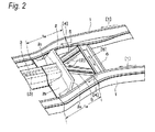
- Fig. 2 is a perspective view showing the structure of a main part of the vehicle body structure according to the embodiment of the invention.
- Fig. 3 is a plan view of the main part shown in Fig. 2 .
- Fig. 4 is a side view of the main part shown in Fig. 2 .
- a pair of left and right side members 1 which extend in a front-to-rear direction of a vehicle body of a vehicle are disposed at both side portions of the vehicle body in a widthwise direction of the vehicle body.
- Rear portions of the side members 1 are raised in height in a step-like fashion in an up-to-down direction of the vehicle body and then extend towards the rear of the vehicle body.
- step portions 1a which rise in a step-like fashion are formed in the side members 1, and portions of the side members 1 which lie further rearwards than the step portions 1 a are made to lie higher than portions of the side members 1 which lie further forwards than the step portions 1 a.
- a rear cross member 2 is disposed at a front portion of the kick-up floor portion, that is, between the step portions 1 a of the pair of side members 1, and this rear cross member 2 functions as a first cross member which extends in the widthwise direction of the vehicle body to connect the pair of side members 1 each other. Both end portions of the rear cross member 2 are joined to the pair of corresponding side members.
- a backbone 3 which acts as a center member which extends in the front-to-rear direction of the vehicle body, is disposed at a front side of a longitudinal (the widthwise direction of the vehicle body) center portion of the rear cross member 2, and a rear end of the backbone 3 is joined to the rear cross member 2.
- the step portions 1 a of the side members 1 extend towards the rear of the vehicle body while being inclined obliquely upwards, and both end portions of the rear cross member 2 are joined to front sides (lower sides) of the step portions 1a, that is, portions of the side members 1 which lie near portions (bent portion) where the side members 1 are bent upwards at the step portions 1 a for connection thereto.
- the rear cross member 2 includes a vertical wall portion 2a and a lower wall portion 2b.
- the vertical wall portion 2a extends to a height which is substantially as high as the kick-up floor portion, that is, upper ends (rear ends) of the step portions 1 a, and the lower wall portion 2b extends to the front from a lower portion of the vertical wall portion 2a.
- a hat portion 2c which projects upwards is formed at a longitudinal (the widthwise direction of the vehicle body) center portion of the lower wall portion 2b, and a rear end of the backbone 3 is inserted underneath a lower surface of the hat portion 2c to be joined to the rear cross member 2.
- the backbone 3 is a tunnel-shaped member having an upwardly projecting cross section and extends in the front-to-rear direction of the vehicle body at the central portion in the widthwise direction of the vehicle body so as to form a floor tunnel.
- the backbone 3 projects to a height which is as high as an upper surface of the kick-up floor portion, that is, rear ends of the step portions 1 a of the side members 1.
- a rear floor cross member 6 is disposed behind the rear cross member 2 as a second cross member which extends in the widthwise direction of the vehicle body, and end portions of the rear floor cross member 6 are joined to the pair of corresponding side members 1.
- a pair of left and right connecting members 5 are disposed at a rear side of the rear cross member 2 so as to extend in the front-to-rear direction of the vehicle body. Front ends of the pair of connecting members 5 are connected to a portion of the rear cross member 2 which lies near the longitudinal center portion thereof. Specifically, the front ends of the pair of connecting members 5 are connected to an upper portion 2a of the vertical wall portion 2a in a position which corresponds to the hat portion 2c to which the backbone 3 is connected to the rear cross member 2. Then, the front ends of the pair of connecting members 5 are connected the rear cross member 2 so as to correspond to the rear end of the backbone 3 in the front-to-rear direction of the vehicle body.
- rear end portions of the pair of connecting members 5 extend outwards in the widthwise direction of the vehicle body to be connected to the side members 1 together with both end portions of the rear floor cross member 6 in positions which lie further rearwards than the step portions 1 a.
- rear ends of the connecting members 5 are joined to the portions of the side members 1 where the end portions of the rear floor cross member 6 are joined.
- the pair of side members 5 are disposed so as to be inclined inwards in the widthwise direction of the vehicle body from the side members 1 towards the backbone 3, and the rear floor cross member 6 is disposed between the rear ends of the pair of connecting members 5 so as to connect the rear ends of the pair of connecting members 5 together.
- front ends of the pair of connecting members 5 are described as being connected directly to the rear side of the vertical wall portion 2a of the rear cross member 2, a configuration can be adopted in which the front ends of the pair of connecting members 5 or the rear end of the backbone 3 is caused to penetrate through the vertical wall portion 2a of the rear cross member 2 so that the front ends of the pair of connecting members 5 and the rear end of the backbone 3 are joined directly to each other.
- a configuration can also be adopted in which a connecting member is attached to the rear side of the vertical wall portion 2a of the rear cross member 2 so that the front ends of the pair of connecting members 5 are joined to the connecting member.
- a rear floor pan 8 is provided on upper surfaces of the pair of side members 1, the rear cross member 2, the rear floor cross member 6 and the pair of connecting member 5, whereby the kick-up floor portion is made up.
- a rear seat or the like is placed at the kick-up floor portion so as to form a space where to accommodate rear seat passengers.
- the loadings are transmitted to the connecting members 5 from the connecting portions with the side members 1 and are then transmitted from the front ends of the connecting members 5 to the backbone 3.
- the loadings acting on the side members 1 be transmitted to the backbone 3 via the connecting members 5 but also part of the loadings can be received by the rear floor cross member 6 as a tensile loading.
- the forward loadings acting on the side members 1 are dispersed in different directions to be received by the connecting portion of the side members 1 with the connecting members 5 and the rear floor cross member 6 so as to be transmitted to the backbone 3 in an ensured fashion, thereby making it possible to reduce the forward loadings acting on the side members 1.
- the increase in weight of the structure can be restricted to a smallest level without enhancing the rigidity of the material of the side members 1 or adding a reinforcement member thereto, and the loadings from the rear can be dispersed accurately to the front of the vehicle body.
- the loadings acting on the side members 1 from the rear act as bending moments at the step portions 1 a of the front portion of the kick-up floor portion
- the loadings from the rear are transmitted to the backbone 3 via the connecting members 5 while being dispersed and are also dispersed to the rear floor cross member 6.
- the loadings acting on the side members 1 from the rear can be reduced in the way described above, the bending moments can be reduced.
- the height of the vertical wall portion 2a of the rear cross member 2 and the height of the backbone 3 are set almost the same as that of the kick-up floor portion, that is, those of the portions of the side members 1 which lie further rearwards than the step portions 1a and the connecting members 5 are caused to extend substantially horizontally to be connected to the backbone 3 which lies ahead of them, the loadings that are dispersed via the connecting members 5 can be transmitted to the backbone 3 as axial loadings, thereby making it possible to reduce more the bending moments in the step portions 1a.
- Fig. 5 shows a concept illustrating how loadings are inputted into the vehicle body structure described above.
- the loadings When loadings are inputted from the rear (arrows ), the loadings are transmitted to the connecting members 5 (arrows ) from the portions where the connecting members 5 are connected to the side members 1 and are then transmitted to the backbone 3 from the front ends of the connecting members 5 (arrows ). At the same time, the loadings which are reduced after being dispersed are transmitted to the front of the side members 1 (arrows ).
- the loadings (the arrows ) from the rear are dispersed into the loadings which are transmitted to the backbone 3 in the direction of the arrow and the loadings which are transmitted to the front of the side members 1 in the direction of the arrows.
- part of the loadings (the arrows ) acting on the side members 1 can be changed into the tensile loading (the arrows ) acting in an axial direction of the rear floor cross member 6 to be absorbed by connecting the rear ends of the connecting members 5 each other by the rear floor cross member 6.
- the stable structure is formed by forming the triangles by the connecting members 5 and the rear floor cross member 6.
- the loadings which are inputted into the side members 1 from the rear can be dispersed to the front of the side members 1 and the backbone 3. Additionally, the loadings which are inputted into the side members 1 from the rear can be changed into the tensile loading in the rear floor cross member 6 to be absorbed.
- the loadings inputted into the side members 1 from the rear can accurately be dispersed without enhancing the rigidity of the material of the side members 1 or increasing the weight of the structure by adding reinforcement members, whereby the deformation at the side members 1 or particularly at the step portions 1a can be restricted. Consequently, the kick-up floor portion is restricted from being deformed, whereby not only can the passenger accommodating space be secured, but also the component such as the fuel tank which is placed underneath the kick-up floor portion can be protected.
- Figs. 6 and 7 are schematic plan views of vehicle body structures according to other embodiments of the invention. Like reference numerals will be given to like members to those shown in Figs. 1 to 5 .
- connecting portions of side members 1 with a rear floor cross member 6 are situated further forwards than connecting portions of the side members 1 with rear ends of connecting members 5. Namely, the rear floor cross member 6 is joined to halfway portions of the pair of connecting members 5, and both ends of the rear floor cross member 6 are joined to the corresponding side members 1.
- reinforcement plates 11 are provided in spaces which are defined by portions of the rear floor cross member 6 which are situated outboards of the connecting members 5 and portions of the connecting members 5 which are situated between the rear floor cross member 6 to the rear ends of the connecting members 5.
- a connecting member 15 is attached to a rear side of a vertical wall portion 2a of a rear cross member 2 which corresponds to a connecting portion of a backbone 3, and a pair of connecting members 5 are joined to the connecting member 15. Then, both ends of a connecting cross member 16 are joined to halfway portions of the connecting members 5.
- Loadings applied to side members 1 from the rear are dispersed from the connecting members 5 to the backbone 3 via the connecting member 15, and a tensile force is generated in the connecting cross member 16 to be absorbed.
- the loadings applied to the side members from the rear are transmitted to the two connecting members and are then transmitted from front ends of the two connecting members to the center member to be dispersed. Then, the loadings which are directed outwards of the vehicle are applied to the rear ends of the two connecting members, a tensile force acts in the second cross member and the loadings applied to the side members from the rear are dispersed as the tensile force in the second cross member.
- the increase in weight of the structure is restricted to the smallest level without enhancing the rigidity of the material of the side members or adding reinforcement members, and the loadings from the rear can accurately be dispersed.
- both the end portions of the second cross member are joined to the corresponding side members, the tensile force acting on the second cross member can be received by the side members.
- the loadings which are inputted into the side members from the rear can be divided into the connecting members in the positions which are situated further rearwards than the step portions, the loadings to be inputted into the step portions are reduced, thereby making it possible to restrict the generation of bending moments in the step portions where stress is easy to be collected in an ensured fashion.
- the loadings which are dispersed to the connecting members can be transmitted to the backbone lying ahead as the axial loading, the generation of bending moments in the step portions can be restricted further.
- the increase in weight of the structure can be restricted to the smallest level without enhancing the rigidity of the material of the side members or adding reinforcement members, and the loadings from the rear can accurately be dispersed.
Landscapes
- Engineering & Computer Science (AREA)
- Chemical & Material Sciences (AREA)
- Combustion & Propulsion (AREA)
- Transportation (AREA)
- Mechanical Engineering (AREA)
- Body Structure For Vehicles (AREA)
Applications Claiming Priority (1)
| Application Number | Priority Date | Filing Date | Title |
|---|---|---|---|
| JP2014194384A JP6478011B2 (ja) | 2014-09-24 | 2014-09-24 | 車体構造 |
Publications (2)
| Publication Number | Publication Date |
|---|---|
| EP3000694A1 true EP3000694A1 (fr) | 2016-03-30 |
| EP3000694B1 EP3000694B1 (fr) | 2018-12-26 |
Family
ID=54196871
Family Applications (1)
| Application Number | Title | Priority Date | Filing Date |
|---|---|---|---|
| EP15186388.3A Active EP3000694B1 (fr) | 2014-09-24 | 2015-09-23 | Carrosserie de vehicule |
Country Status (4)
| Country | Link |
|---|---|
| US (1) | US9550530B2 (fr) |
| EP (1) | EP3000694B1 (fr) |
| JP (1) | JP6478011B2 (fr) |
| CN (1) | CN105438275B (fr) |
Cited By (2)
| Publication number | Priority date | Publication date | Assignee | Title |
|---|---|---|---|---|
| EP3686092A1 (fr) * | 2019-01-23 | 2020-07-29 | Mazda Motor Corporation | Structure arrière de carrosserie de véhicule et véhicule |
| EP3686091A1 (fr) * | 2019-01-23 | 2020-07-29 | Mazda Motor Corporation | Structure arrière de carrosserie de véhicule et véhicule |
Families Citing this family (15)
| Publication number | Priority date | Publication date | Assignee | Title |
|---|---|---|---|---|
| US9604671B2 (en) * | 2015-08-13 | 2017-03-28 | Fca Us Llc | Vehicle underbody structure |
| JP6253625B2 (ja) * | 2015-10-20 | 2017-12-27 | 本田技研工業株式会社 | 車体後部構造 |
| DE102016212297A1 (de) * | 2016-07-06 | 2018-01-11 | Bayerische Motoren Werke Aktiengesellschaft | Kraftfahrzeug |
| US9981698B2 (en) * | 2016-09-07 | 2018-05-29 | Thunder Power New Energy Vehicle Development Company Limited | Vehicle tunnel floor structure |
| JP6977307B2 (ja) * | 2017-04-28 | 2021-12-08 | トヨタ自動車株式会社 | 車両下部構造 |
| JP6964939B2 (ja) * | 2017-07-31 | 2021-11-10 | ダイハツ工業株式会社 | 車両の下部構造 |
| FR3080353B1 (fr) * | 2018-04-19 | 2020-03-20 | Psa Automobiles Sa | Structure de caisse de vehicule automobile avec renfort de traverse d’assise arriere |
| JP7040381B2 (ja) * | 2018-09-25 | 2022-03-23 | マツダ株式会社 | 後部車体構造 |
| CN111942480B (zh) * | 2019-05-15 | 2022-11-22 | 马自达汽车株式会社 | 电动车辆的下部车体构造 |
| JPWO2020261917A1 (fr) * | 2019-06-27 | 2020-12-30 | ||
| KR102614164B1 (ko) | 2019-07-25 | 2023-12-13 | 현대자동차주식회사 | 차량의 프런트 차체 |
| CN113104117B (zh) * | 2020-01-13 | 2022-08-12 | 宇通客车股份有限公司 | 前置客车及其前地板骨架 |
| KR20220093749A (ko) * | 2020-12-28 | 2022-07-05 | 현대자동차주식회사 | 차량의 후방 구조 |
| KR20220096102A (ko) * | 2020-12-30 | 2022-07-07 | 현대자동차주식회사 | 리어 플로어 사이드 멤버 어셈블리 |
| CN113815734A (zh) * | 2021-11-02 | 2021-12-21 | 上海洛轲智能科技有限公司 | 一种车身系统结构 |
Citations (5)
| Publication number | Priority date | Publication date | Assignee | Title |
|---|---|---|---|---|
| JPH09118252A (ja) * | 1995-10-24 | 1997-05-06 | Mazda Motor Corp | 自動車の下部車体構造 |
| JP2003095141A (ja) * | 2001-09-25 | 2003-04-03 | Mazda Motor Corp | 車両の下部車体構造 |
| US20050077756A1 (en) * | 2003-10-14 | 2005-04-14 | Fuji Jukogyo Kabushiki Kaisha | Frame structure for vehicle |
| JP2010195257A (ja) * | 2009-02-26 | 2010-09-09 | Mazda Motor Corp | 車両の後部車体構造 |
| JP4571340B2 (ja) | 2001-06-15 | 2010-10-27 | 富士重工業株式会社 | 自動車の車体後部構造 |
Family Cites Families (7)
| Publication number | Priority date | Publication date | Assignee | Title |
|---|---|---|---|---|
| JP2005029103A (ja) * | 2003-07-11 | 2005-02-03 | Mazda Motor Corp | 車両の車体構造 |
| FR2885109B1 (fr) * | 2005-04-27 | 2008-12-05 | Plastic Omnium Cie | Bloc arriere, plancher arriere et renfort de vehicule automobile |
| JP5099145B2 (ja) * | 2007-12-07 | 2012-12-12 | トヨタ自動車株式会社 | 車体下部構造 |
| JP5614871B2 (ja) | 2009-02-23 | 2014-10-29 | ロンシール工業株式会社 | 熱可塑性樹脂製遮熱床シート |
| US8439431B2 (en) * | 2011-05-31 | 2013-05-14 | Ford Global Technologies, Llc | Attachment bracket for connecting peripheral devices to a vehicle |
| US8820823B1 (en) * | 2013-03-12 | 2014-09-02 | Honda Motor Co., Ltd. | Vehicle frame structure |
| JP6541169B2 (ja) * | 2014-08-25 | 2019-07-10 | 三菱自動車工業株式会社 | 車両の後部構造 |
-
2014
- 2014-09-24 JP JP2014194384A patent/JP6478011B2/ja active Active
-
2015
- 2015-09-23 CN CN201510612611.6A patent/CN105438275B/zh active Active
- 2015-09-23 US US14/862,614 patent/US9550530B2/en active Active
- 2015-09-23 EP EP15186388.3A patent/EP3000694B1/fr active Active
Patent Citations (5)
| Publication number | Priority date | Publication date | Assignee | Title |
|---|---|---|---|---|
| JPH09118252A (ja) * | 1995-10-24 | 1997-05-06 | Mazda Motor Corp | 自動車の下部車体構造 |
| JP4571340B2 (ja) | 2001-06-15 | 2010-10-27 | 富士重工業株式会社 | 自動車の車体後部構造 |
| JP2003095141A (ja) * | 2001-09-25 | 2003-04-03 | Mazda Motor Corp | 車両の下部車体構造 |
| US20050077756A1 (en) * | 2003-10-14 | 2005-04-14 | Fuji Jukogyo Kabushiki Kaisha | Frame structure for vehicle |
| JP2010195257A (ja) * | 2009-02-26 | 2010-09-09 | Mazda Motor Corp | 車両の後部車体構造 |
Cited By (3)
| Publication number | Priority date | Publication date | Assignee | Title |
|---|---|---|---|---|
| EP3686092A1 (fr) * | 2019-01-23 | 2020-07-29 | Mazda Motor Corporation | Structure arrière de carrosserie de véhicule et véhicule |
| EP3686091A1 (fr) * | 2019-01-23 | 2020-07-29 | Mazda Motor Corporation | Structure arrière de carrosserie de véhicule et véhicule |
| CN111469934A (zh) * | 2019-01-23 | 2020-07-31 | 马自达汽车株式会社 | 后部车身结构 |
Also Published As
| Publication number | Publication date |
|---|---|
| CN105438275A (zh) | 2016-03-30 |
| US9550530B2 (en) | 2017-01-24 |
| US20160083011A1 (en) | 2016-03-24 |
| JP6478011B2 (ja) | 2019-03-06 |
| CN105438275B (zh) | 2018-04-03 |
| EP3000694B1 (fr) | 2018-12-26 |
| JP2016064730A (ja) | 2016-04-28 |
Similar Documents
| Publication | Publication Date | Title |
|---|---|---|
| EP3000694B1 (fr) | Carrosserie de vehicule | |
| KR101628479B1 (ko) | 프런트 사이드 멤버 후방 구조 | |
| US10112651B2 (en) | Vehicle body front structure | |
| US8328272B2 (en) | Lower structure of vehicle body rear portion | |
| EP2805875A1 (fr) | Carrosserie de véhicule | |
| EP3067253A2 (fr) | Carrosserie inférieur cadre structure | |
| CN108974133B (zh) | 车身前部构造 | |
| JP6584457B2 (ja) | 車体前部構造 | |
| CN106043458A (zh) | 汽车的后部车身构造 | |
| JP6574947B2 (ja) | 車体下部構造 | |
| JP2017121883A (ja) | 車体前部構造 | |
| CN102476656B (zh) | 车身后部构造 | |
| CN107303920B (zh) | 车身前部构造 | |
| CN205524470U (zh) | 用于车辆前部的车身布置结构 | |
| US20170057553A1 (en) | Vehicle lower portion structure | |
| CN112298366A (zh) | 车身的横梁结构 | |
| JP6915255B2 (ja) | 車両の荷重伝達システム | |
| CN106515629B (zh) | 车体框架结构 | |
| CN210027590U (zh) | 一种前纵梁连接件及汽车 | |
| JP2014218182A (ja) | 車両前部構造 | |
| CN105459940A (zh) | 车辆后部构造 | |
| CN110198884B (zh) | 车辆用车身结构 | |
| JP6491927B2 (ja) | 車体前部構造 | |
| CN108454715A (zh) | 驾驶室加强构造 | |
| US10689040B2 (en) | Vehicle underbody |
Legal Events
| Date | Code | Title | Description |
|---|---|---|---|
| PUAI | Public reference made under article 153(3) epc to a published international application that has entered the european phase |
Free format text: ORIGINAL CODE: 0009012 |
|
| 17P | Request for examination filed |
Effective date: 20150923 |
|
| AK | Designated contracting states |
Kind code of ref document: A1 Designated state(s): AL AT BE BG CH CY CZ DE DK EE ES FI FR GB GR HR HU IE IS IT LI LT LU LV MC MK MT NL NO PL PT RO RS SE SI SK SM TR |
|
| AX | Request for extension of the european patent |
Extension state: BA ME |
|
| GRAP | Despatch of communication of intention to grant a patent |
Free format text: ORIGINAL CODE: EPIDOSNIGR1 |
|
| STAA | Information on the status of an ep patent application or granted ep patent |
Free format text: STATUS: GRANT OF PATENT IS INTENDED |
|
| RIC1 | Information provided on ipc code assigned before grant |
Ipc: B62D 25/20 20060101ALI20180709BHEP Ipc: B62D 25/08 20060101ALI20180709BHEP Ipc: B62D 21/08 20060101ALI20180709BHEP Ipc: B62D 21/02 20060101ALI20180709BHEP Ipc: B62D 21/15 20060101AFI20180709BHEP |
|
| INTG | Intention to grant announced |
Effective date: 20180724 |
|
| RAP1 | Party data changed (applicant data changed or rights of an application transferred) |
Owner name: MITSUBISHI JIDOSHA KOGYO KABUSHIKI KAISHA |
|
| GRAS | Grant fee paid |
Free format text: ORIGINAL CODE: EPIDOSNIGR3 |
|
| GRAA | (expected) grant |
Free format text: ORIGINAL CODE: 0009210 |
|
| STAA | Information on the status of an ep patent application or granted ep patent |
Free format text: STATUS: THE PATENT HAS BEEN GRANTED |
|
| AK | Designated contracting states |
Kind code of ref document: B1 Designated state(s): AL AT BE BG CH CY CZ DE DK EE ES FI FR GB GR HR HU IE IS IT LI LT LU LV MC MK MT NL NO PL PT RO RS SE SI SK SM TR |
|
| REG | Reference to a national code |
Ref country code: GB Ref legal event code: FG4D |
|
| REG | Reference to a national code |
Ref country code: CH Ref legal event code: EP |
|
| REG | Reference to a national code |
Ref country code: AT Ref legal event code: REF Ref document number: 1081012 Country of ref document: AT Kind code of ref document: T Effective date: 20190115 |
|
| REG | Reference to a national code |
Ref country code: IE Ref legal event code: FG4D |
|
| REG | Reference to a national code |
Ref country code: DE Ref legal event code: R096 Ref document number: 602015022167 Country of ref document: DE |
|
| PG25 | Lapsed in a contracting state [announced via postgrant information from national office to epo] |
Ref country code: HR Free format text: LAPSE BECAUSE OF FAILURE TO SUBMIT A TRANSLATION OF THE DESCRIPTION OR TO PAY THE FEE WITHIN THE PRESCRIBED TIME-LIMIT Effective date: 20181226 Ref country code: LT Free format text: LAPSE BECAUSE OF FAILURE TO SUBMIT A TRANSLATION OF THE DESCRIPTION OR TO PAY THE FEE WITHIN THE PRESCRIBED TIME-LIMIT Effective date: 20181226 Ref country code: NO Free format text: LAPSE BECAUSE OF FAILURE TO SUBMIT A TRANSLATION OF THE DESCRIPTION OR TO PAY THE FEE WITHIN THE PRESCRIBED TIME-LIMIT Effective date: 20190326 Ref country code: BG Free format text: LAPSE BECAUSE OF FAILURE TO SUBMIT A TRANSLATION OF THE DESCRIPTION OR TO PAY THE FEE WITHIN THE PRESCRIBED TIME-LIMIT Effective date: 20190326 Ref country code: FI Free format text: LAPSE BECAUSE OF FAILURE TO SUBMIT A TRANSLATION OF THE DESCRIPTION OR TO PAY THE FEE WITHIN THE PRESCRIBED TIME-LIMIT Effective date: 20181226 Ref country code: LV Free format text: LAPSE BECAUSE OF FAILURE TO SUBMIT A TRANSLATION OF THE DESCRIPTION OR TO PAY THE FEE WITHIN THE PRESCRIBED TIME-LIMIT Effective date: 20181226 |
|
| REG | Reference to a national code |
Ref country code: NL Ref legal event code: MP Effective date: 20181226 |
|
| REG | Reference to a national code |
Ref country code: LT Ref legal event code: MG4D |
|
| PG25 | Lapsed in a contracting state [announced via postgrant information from national office to epo] |
Ref country code: RS Free format text: LAPSE BECAUSE OF FAILURE TO SUBMIT A TRANSLATION OF THE DESCRIPTION OR TO PAY THE FEE WITHIN THE PRESCRIBED TIME-LIMIT Effective date: 20181226 Ref country code: SE Free format text: LAPSE BECAUSE OF FAILURE TO SUBMIT A TRANSLATION OF THE DESCRIPTION OR TO PAY THE FEE WITHIN THE PRESCRIBED TIME-LIMIT Effective date: 20181226 Ref country code: AL Free format text: LAPSE BECAUSE OF FAILURE TO SUBMIT A TRANSLATION OF THE DESCRIPTION OR TO PAY THE FEE WITHIN THE PRESCRIBED TIME-LIMIT Effective date: 20181226 Ref country code: GR Free format text: LAPSE BECAUSE OF FAILURE TO SUBMIT A TRANSLATION OF THE DESCRIPTION OR TO PAY THE FEE WITHIN THE PRESCRIBED TIME-LIMIT Effective date: 20190327 |
|
| REG | Reference to a national code |
Ref country code: AT Ref legal event code: MK05 Ref document number: 1081012 Country of ref document: AT Kind code of ref document: T Effective date: 20181226 |
|
| PG25 | Lapsed in a contracting state [announced via postgrant information from national office to epo] |
Ref country code: NL Free format text: LAPSE BECAUSE OF FAILURE TO SUBMIT A TRANSLATION OF THE DESCRIPTION OR TO PAY THE FEE WITHIN THE PRESCRIBED TIME-LIMIT Effective date: 20181226 |
|
| RAP2 | Party data changed (patent owner data changed or rights of a patent transferred) |
Owner name: MITSUBISHI JIDOSHA KOGYO KABUSHIKI KAISHA |
|
| PG25 | Lapsed in a contracting state [announced via postgrant information from national office to epo] |
Ref country code: PL Free format text: LAPSE BECAUSE OF FAILURE TO SUBMIT A TRANSLATION OF THE DESCRIPTION OR TO PAY THE FEE WITHIN THE PRESCRIBED TIME-LIMIT Effective date: 20181226 Ref country code: PT Free format text: LAPSE BECAUSE OF FAILURE TO SUBMIT A TRANSLATION OF THE DESCRIPTION OR TO PAY THE FEE WITHIN THE PRESCRIBED TIME-LIMIT Effective date: 20190426 Ref country code: IT Free format text: LAPSE BECAUSE OF FAILURE TO SUBMIT A TRANSLATION OF THE DESCRIPTION OR TO PAY THE FEE WITHIN THE PRESCRIBED TIME-LIMIT Effective date: 20181226 Ref country code: ES Free format text: LAPSE BECAUSE OF FAILURE TO SUBMIT A TRANSLATION OF THE DESCRIPTION OR TO PAY THE FEE WITHIN THE PRESCRIBED TIME-LIMIT Effective date: 20181226 Ref country code: CZ Free format text: LAPSE BECAUSE OF FAILURE TO SUBMIT A TRANSLATION OF THE DESCRIPTION OR TO PAY THE FEE WITHIN THE PRESCRIBED TIME-LIMIT Effective date: 20181226 |
|
| PG25 | Lapsed in a contracting state [announced via postgrant information from national office to epo] |
Ref country code: RO Free format text: LAPSE BECAUSE OF FAILURE TO SUBMIT A TRANSLATION OF THE DESCRIPTION OR TO PAY THE FEE WITHIN THE PRESCRIBED TIME-LIMIT Effective date: 20181226 Ref country code: IS Free format text: LAPSE BECAUSE OF FAILURE TO SUBMIT A TRANSLATION OF THE DESCRIPTION OR TO PAY THE FEE WITHIN THE PRESCRIBED TIME-LIMIT Effective date: 20190426 Ref country code: SM Free format text: LAPSE BECAUSE OF FAILURE TO SUBMIT A TRANSLATION OF THE DESCRIPTION OR TO PAY THE FEE WITHIN THE PRESCRIBED TIME-LIMIT Effective date: 20181226 Ref country code: EE Free format text: LAPSE BECAUSE OF FAILURE TO SUBMIT A TRANSLATION OF THE DESCRIPTION OR TO PAY THE FEE WITHIN THE PRESCRIBED TIME-LIMIT Effective date: 20181226 Ref country code: SK Free format text: LAPSE BECAUSE OF FAILURE TO SUBMIT A TRANSLATION OF THE DESCRIPTION OR TO PAY THE FEE WITHIN THE PRESCRIBED TIME-LIMIT Effective date: 20181226 |
|
| REG | Reference to a national code |
Ref country code: DE Ref legal event code: R097 Ref document number: 602015022167 Country of ref document: DE |
|
| PG25 | Lapsed in a contracting state [announced via postgrant information from national office to epo] |
Ref country code: DK Free format text: LAPSE BECAUSE OF FAILURE TO SUBMIT A TRANSLATION OF THE DESCRIPTION OR TO PAY THE FEE WITHIN THE PRESCRIBED TIME-LIMIT Effective date: 20181226 Ref country code: AT Free format text: LAPSE BECAUSE OF FAILURE TO SUBMIT A TRANSLATION OF THE DESCRIPTION OR TO PAY THE FEE WITHIN THE PRESCRIBED TIME-LIMIT Effective date: 20181226 |
|
| PLBE | No opposition filed within time limit |
Free format text: ORIGINAL CODE: 0009261 |
|
| STAA | Information on the status of an ep patent application or granted ep patent |
Free format text: STATUS: NO OPPOSITION FILED WITHIN TIME LIMIT |
|
| 26N | No opposition filed |
Effective date: 20190927 |
|
| PG25 | Lapsed in a contracting state [announced via postgrant information from national office to epo] |
Ref country code: SI Free format text: LAPSE BECAUSE OF FAILURE TO SUBMIT A TRANSLATION OF THE DESCRIPTION OR TO PAY THE FEE WITHIN THE PRESCRIBED TIME-LIMIT Effective date: 20181226 |
|
| PG25 | Lapsed in a contracting state [announced via postgrant information from national office to epo] |
Ref country code: TR Free format text: LAPSE BECAUSE OF FAILURE TO SUBMIT A TRANSLATION OF THE DESCRIPTION OR TO PAY THE FEE WITHIN THE PRESCRIBED TIME-LIMIT Effective date: 20181226 |
|
| PG25 | Lapsed in a contracting state [announced via postgrant information from national office to epo] |
Ref country code: MC Free format text: LAPSE BECAUSE OF FAILURE TO SUBMIT A TRANSLATION OF THE DESCRIPTION OR TO PAY THE FEE WITHIN THE PRESCRIBED TIME-LIMIT Effective date: 20181226 |
|
| REG | Reference to a national code |
Ref country code: CH Ref legal event code: PL |
|
| PG25 | Lapsed in a contracting state [announced via postgrant information from national office to epo] |
Ref country code: IE Free format text: LAPSE BECAUSE OF NON-PAYMENT OF DUE FEES Effective date: 20190923 Ref country code: LI Free format text: LAPSE BECAUSE OF NON-PAYMENT OF DUE FEES Effective date: 20190930 Ref country code: LU Free format text: LAPSE BECAUSE OF NON-PAYMENT OF DUE FEES Effective date: 20190923 Ref country code: CH Free format text: LAPSE BECAUSE OF NON-PAYMENT OF DUE FEES Effective date: 20190930 |
|
| REG | Reference to a national code |
Ref country code: BE Ref legal event code: MM Effective date: 20190930 |
|
| PG25 | Lapsed in a contracting state [announced via postgrant information from national office to epo] |
Ref country code: BE Free format text: LAPSE BECAUSE OF NON-PAYMENT OF DUE FEES Effective date: 20190930 |
|
| GBPC | Gb: european patent ceased through non-payment of renewal fee |
Effective date: 20190923 |
|
| PG25 | Lapsed in a contracting state [announced via postgrant information from national office to epo] |
Ref country code: GB Free format text: LAPSE BECAUSE OF NON-PAYMENT OF DUE FEES Effective date: 20190923 |
|
| PG25 | Lapsed in a contracting state [announced via postgrant information from national office to epo] |
Ref country code: CY Free format text: LAPSE BECAUSE OF FAILURE TO SUBMIT A TRANSLATION OF THE DESCRIPTION OR TO PAY THE FEE WITHIN THE PRESCRIBED TIME-LIMIT Effective date: 20181226 |
|
| PG25 | Lapsed in a contracting state [announced via postgrant information from national office to epo] |
Ref country code: MT Free format text: LAPSE BECAUSE OF FAILURE TO SUBMIT A TRANSLATION OF THE DESCRIPTION OR TO PAY THE FEE WITHIN THE PRESCRIBED TIME-LIMIT Effective date: 20181226 Ref country code: HU Free format text: LAPSE BECAUSE OF FAILURE TO SUBMIT A TRANSLATION OF THE DESCRIPTION OR TO PAY THE FEE WITHIN THE PRESCRIBED TIME-LIMIT; INVALID AB INITIO Effective date: 20150923 |
|
| PG25 | Lapsed in a contracting state [announced via postgrant information from national office to epo] |
Ref country code: MK Free format text: LAPSE BECAUSE OF FAILURE TO SUBMIT A TRANSLATION OF THE DESCRIPTION OR TO PAY THE FEE WITHIN THE PRESCRIBED TIME-LIMIT Effective date: 20181226 |
|
| PGFP | Annual fee paid to national office [announced via postgrant information from national office to epo] |
Ref country code: FR Payment date: 20230808 Year of fee payment: 9 Ref country code: DE Payment date: 20230802 Year of fee payment: 9 |