EP3000503B1 - Katheter - Google Patents
Katheter Download PDFInfo
- Publication number
- EP3000503B1 EP3000503B1 EP14800887.3A EP14800887A EP3000503B1 EP 3000503 B1 EP3000503 B1 EP 3000503B1 EP 14800887 A EP14800887 A EP 14800887A EP 3000503 B1 EP3000503 B1 EP 3000503B1
- Authority
- EP
- European Patent Office
- Prior art keywords
- connector
- sheath
- tube
- outer tube
- unit
- Prior art date
- Legal status (The legal status is an assumption and is not a legal conclusion. Google has not performed a legal analysis and makes no representation as to the accuracy of the status listed.)
- Active
Links
Images


Classifications
-
- A—HUMAN NECESSITIES
- A61—MEDICAL OR VETERINARY SCIENCE; HYGIENE
- A61B—DIAGNOSIS; SURGERY; IDENTIFICATION
- A61B8/00—Diagnosis using ultrasonic, sonic or infrasonic waves
- A61B8/12—Diagnosis using ultrasonic, sonic or infrasonic waves in body cavities or body tracts, e.g. by using catheters
-
- A—HUMAN NECESSITIES
- A61—MEDICAL OR VETERINARY SCIENCE; HYGIENE
- A61M—DEVICES FOR INTRODUCING MEDIA INTO, OR ONTO, THE BODY; DEVICES FOR TRANSDUCING BODY MEDIA OR FOR TAKING MEDIA FROM THE BODY; DEVICES FOR PRODUCING OR ENDING SLEEP OR STUPOR
- A61M25/00—Catheters; Hollow probes
- A61M25/0097—Catheters; Hollow probes characterised by the hub
-
- A—HUMAN NECESSITIES
- A61—MEDICAL OR VETERINARY SCIENCE; HYGIENE
- A61M—DEVICES FOR INTRODUCING MEDIA INTO, OR ONTO, THE BODY; DEVICES FOR TRANSDUCING BODY MEDIA OR FOR TAKING MEDIA FROM THE BODY; DEVICES FOR PRODUCING OR ENDING SLEEP OR STUPOR
- A61M25/00—Catheters; Hollow probes
- A61M25/01—Introducing, guiding, advancing, emplacing or holding catheters
-
- A—HUMAN NECESSITIES
- A61—MEDICAL OR VETERINARY SCIENCE; HYGIENE
- A61M—DEVICES FOR INTRODUCING MEDIA INTO, OR ONTO, THE BODY; DEVICES FOR TRANSDUCING BODY MEDIA OR FOR TAKING MEDIA FROM THE BODY; DEVICES FOR PRODUCING OR ENDING SLEEP OR STUPOR
- A61M39/00—Tubes, tube connectors, tube couplings, valves, access sites or the like, specially adapted for medical use
- A61M39/10—Tube connectors; Tube couplings
-
- A—HUMAN NECESSITIES
- A61—MEDICAL OR VETERINARY SCIENCE; HYGIENE
- A61M—DEVICES FOR INTRODUCING MEDIA INTO, OR ONTO, THE BODY; DEVICES FOR TRANSDUCING BODY MEDIA OR FOR TAKING MEDIA FROM THE BODY; DEVICES FOR PRODUCING OR ENDING SLEEP OR STUPOR
- A61M25/00—Catheters; Hollow probes
- A61M2025/0004—Catheters; Hollow probes having two or more concentrically arranged tubes for forming a concentric catheter system
-
- A—HUMAN NECESSITIES
- A61—MEDICAL OR VETERINARY SCIENCE; HYGIENE
- A61M—DEVICES FOR INTRODUCING MEDIA INTO, OR ONTO, THE BODY; DEVICES FOR TRANSDUCING BODY MEDIA OR FOR TAKING MEDIA FROM THE BODY; DEVICES FOR PRODUCING OR ENDING SLEEP OR STUPOR
- A61M25/00—Catheters; Hollow probes
- A61M25/01—Introducing, guiding, advancing, emplacing or holding catheters
- A61M2025/0175—Introducing, guiding, advancing, emplacing or holding catheters having telescopic features, interengaging nestable members movable in relations to one another
-
- A—HUMAN NECESSITIES
- A61—MEDICAL OR VETERINARY SCIENCE; HYGIENE
- A61M—DEVICES FOR INTRODUCING MEDIA INTO, OR ONTO, THE BODY; DEVICES FOR TRANSDUCING BODY MEDIA OR FOR TAKING MEDIA FROM THE BODY; DEVICES FOR PRODUCING OR ENDING SLEEP OR STUPOR
- A61M25/00—Catheters; Hollow probes
- A61M25/01—Introducing, guiding, advancing, emplacing or holding catheters
- A61M25/06—Body-piercing guide needles or the like
- A61M25/0662—Guide tubes
- A61M2025/0681—Systems with catheter and outer tubing, e.g. sheath, sleeve or guide tube
-
- A—HUMAN NECESSITIES
- A61—MEDICAL OR VETERINARY SCIENCE; HYGIENE
- A61M—DEVICES FOR INTRODUCING MEDIA INTO, OR ONTO, THE BODY; DEVICES FOR TRANSDUCING BODY MEDIA OR FOR TAKING MEDIA FROM THE BODY; DEVICES FOR PRODUCING OR ENDING SLEEP OR STUPOR
- A61M39/00—Tubes, tube connectors, tube couplings, valves, access sites or the like, specially adapted for medical use
- A61M39/02—Access sites
- A61M39/06—Haemostasis valves, i.e. gaskets sealing around a needle, catheter or the like, closing on removal thereof
- A61M2039/062—Haemostasis valves, i.e. gaskets sealing around a needle, catheter or the like, closing on removal thereof used with a catheter
Definitions
- the present invention relates to a catheter, and particularly relates to a catheter which is inserted into a lumen such as a blood vessel, a Vessel, and the like and acquires an image from the inside of the lumen.
- an ultrasound catheter which transmits and receives ultrasounds at the target lesion is used.
- the ultrasound catheter includes an imaging core that comprises a transducer unit which transmits and receives ultrasounds and a drive shaft which rotates the transducer unit, and a sheath that has the imaging core built in and is inserted into a lumen.
- the imaging core can move inside the sheath in an axial direction.
- an introducer sheath for having access to the inside of the lumen is caused to indwell, and a guiding catheter is inserted into the lumen via the introducer sheath. Thereafter, a guide wire is inserted through the guiding catheter until the guide wire reaches a target place, and the ultrasound catheter is inserted along the guide wire to a site deeper than the target lesion. Then, from a state where the imaging core is disposed inside the sheath on a distal side, only the imaging core is caused to move backward and to pass through the target lesion while leaving the sheath behind.
- the transducer unit moves from the deep site while passing through the target lesion by moving only the imaging core backward, it is possible to observe ultrasound images which are continuously acquired through the front and the rear of the target lesion, and to generate three-dimensional data of shapes of a blood vessel, a Vessel, or the like.
- the ultrasound catheter disclosed in PTL 1 comprises a nested structure for extending and contracting in the axial direction provided in the sheath on a proximal side, the imaging core inside the sheath is caused to move in the axial direction with respect to the sheath by varying the overall length of a catheter main body.
- connection portion which is connectable and disconnectable is provided between the sheath and the nested structure, and the imaging core can be pulled out of the catheter main body in accordance with a situation.
- PTL 1 Pamphlet of International Publication No. WO 1999/015078 , also EP2364746 , which discloses the preamble of claim 1.
- the ultrasound catheter disclosed in PTL 1 is rarely caught by a complicatedly curved blood vessel, a stenosed blood vessel, a stent embedded inside a blood vessel, or the like when being inserted into a blood vessel, thereby being difficult to be pulled out of the blood vessel.
- an imaging core is removed from the inside of a sheath, and a medical instrument, for example, a guide wire (hereinafter, suitably abbreviated to the wire) or the like having rigidity higher than that of the imaging core is inserted in place thereof, and thus the sheath is likely to be pulled out.
- connection portion which is connectable and disconnectable is provided between the sheath and a nested structure, in a state where the ultrasound catheter is inserted into a guiding catheter, the connection portion approaches a Y-connector which is connected to the guiding catheter on a proximal side. Since the guide wire has been also led from the Y-connector, there may be a possibility that the guide wire and the connection portion interfere with each other, and it is difficult to control the guide wire when operating the ultrasound catheter, resulting in degradation of the operability.
- connection portion since the connection portion approaches the Y-connector, there may be a possibility of confusion between blood flowing out from the connection portion and blood flowing out from the Y-connector after the imaging core is extracted, resulting in an erroneous operation. Furthermore, as the connection portion approaches the Y-connector, there may be a possibility that blood flowing out of the connection portion flows into the valve body which is provided in the Y-connector, from the outside, resulting in degradation of the operability.
- the present invention has been made to solve the aforementioned problems, and an objective thereof is to provide a catheter which comprises a connectable and disconnectable portion and comprises high operability.
- a catheter including a sheath that is inserted into a lumen; a drive shaft that is inserted into the sheath and transmits mechanical drive force; a hub that moves the drive shaft in an axial direction of the sheath by holding and moving the drive shaft; an outer tube that is provided in the sheath on a proximal side and comprises a first connector at a proximal portion; an inner tube that is provided in the hub on a distal side and moves relatively to the outer tube inside the outer tube in accordance with a movement of the hub; a second connector that can be connected to and disconnected from the first connector and comprises a pass-through port which can receive the inner tube; a sheath connection portion that connects the sheath and the outer tube; and a protective tube that protrudes toward the distal side further than the inner tube, accommodates the drive shaft, can be inserted into the outer tube and the sheath, and can be pulled out of the outer tube together with the hub and the inner tube
- a second connector provided in an outer tube on a proximal side is disconnectable, the second connector is disposed away from an insertion target, for example, a Y-connector or the like during an operation. Therefore, even when it becomes difficult to pull out the catheter from the inside of a blood vessel, the second connector can be disconnected without being interfered with a guide wire which has been led from the insertion target, and the guide wire at a distant position is easily controlled, thereby improving the operability of the guide wire and the catheter.
- the second connector is away from the insertion target interposing the outer tube therebetween, blood flowing out of the second connector is unlikely to be mistaken for blood flowing out of the insertion target, and an operation can be performed while confirming which the blood is flowing out, thereby improving the operability.
- the second connector is away from the insertion target interposing the outer tube therebetween, blood flowing out of the second connector is unlikely to enter the insertion target from the outside, thereby improving the operability.
- a protective tube which protrudes toward a distal side further than an inner tube, accommodates a drive shaft, and can be inserted into the outer tube and a sheath, the drive shaft can be prevented from bending or the like on account of the protective tube when the inner tube is thrust into or drawn out of the outer tube, and there is no need to insert a wire or the like through the protective tube when the wire or the like is inserted into the sheath, by disconnecting the second connector from a first connector and pulling out the protective tube from the outer tube together with a hub and the inner tube, thereby improving the operability.
- an engagement portion having an enlarged outer diameter is provided in a distal portion of the inner tube, even when the inner tube is drawn out to the fullest extent from the outer tube in a proximal end direction, the engagement portion is caught by the second connector, and thus, the inner tube can be prevented from coming out.
- a sheath connection portion has a seal member which comes into contact with an outer circumferential surface of the protective tube in a slidable manner, blood is prevented from leaking from a lumen of the sheath to the outer tube. Moreover, if a passage allowing the protective tube and the drive shaft to be inserted therethrough is shut by the seal member as the protective tube and the drive shaft are pulled out, blood is prevented from leaking via the lumen of the sheath, thereby improving the safety, and blood does not leak on the hand-side of an operator, thereby improving the operability as well.
- the outer tube is provided the sheath connection portion on the proximal side on which the seal member is provided, blood leaking from the seal member does not reach the outside unless the blood passes through the outer tube further. Therefore, blood is more reliably prevented from leaking via the sheath.
- the protective tube can be moved in accordance with a movement of the inner tube.
- the protective tube can be moved in accordance with a movement of the hub.
- the protective tube is a tubular body which is impermeable to liquid
- priming liquid such as blood, physiological salt liquid, and the like circulating the inside of the protective tube does not leak into the outer tube via the protective tube.
- the volume of priming processing is lessened
- liquid such as blood, physiological salt liquid, and the like does not leak into the outer tube, there is no need to provide the seal member between the outer tube and the inner tube. Then, as liquid such as blood, physiological salt liquid, and the like is prevented from leaking into the outer tube, the liquid is more reliably prevented from leaking out further than the outer tube.
- a slope portion which slopes toward an axial center as being closer to the distal side is formed on an inner circumferential surface of at least one of the outer tube and the sheath connection portion, the wire, the drive shaft, the protective tube, and the like inserted through the outer tube can be smoothly guided into the sheath along the slope portion.
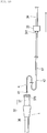
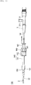
- a catheter according to a first embodiment is an ultrasound catheter 1 which is mainly adopted for diagnosing a state of the inside of a blood vessel through images by being inserted into the blood vessel.
- an imaging core 4 for performing an ultrasound diagnosis has been accommodated inside the ultrasound catheter 1.
- the ultrasound catheter 1 is used by being connected to an external drive apparatus 7 which holds the ultrasound catheter 1 and drives the imaging core 4.
- the distal end or “the distal side”
- a hand-side on which operations are performed is referred to as "the proximal end” or "the proximal side”.
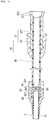
- the ultrasound catheter 1 comprises a sheath 2 which is inserted into a lumen, the imaging core 4 which transmits and receives ultrasounds with respect to a tissue inside the lumen, and an operation unit 3 which is positioned on the proximal side from the sheath 2 while allowing the imaging core 4 to penetrate.
- the sheath 2 includes a sheath distal portion 21, a sheath tube 22, and a filling liquid inflow and outflow path member 23.
- the sheath distal portion 21 is provided with a tubular sheath distal end member 27 in which a guide wire lumen 211 is formed, and an X-ray contrast marker 24 which is provided at a portion slightly closer to the proximal side than the distal portion.
- the ultrasound catheter 1 can be guided to a target lesion along the guide wire 2.
- the X-ray contrast marker 24 is provided so as to be able to confirm a distal end position of the ultrasound catheter 1 through radioscopy when being inserted into the lumen.
- the ultrasound catheter 1 has "a rapid-exchange structure" in which the guide wire lumen 211 is provided at only the distal portion.
- the ultrasound catheter 1 has a structure in which the guide wire lumen 211 does not exist within the range of image-capturing performed by the imaging core 4 so as to prevent image capturing from being hindered by the guide wire lumen 211.
- a priming lumen 231 has been formed in the filling liquid inflow and outflow path member 23.
- the priming lumen 231 is a hole which communicates with a lumen 26 inside the sheath tube 22 and through which physiological salt liquid filling the inside of the sheath tube 22 flows to the outside.
- the imaging core 4 has been built in the sheath 2 in the axial direction of the sheath 2 in a slidable manner.
- the imaging core 4 comprises a transducer unit 41 for transmitting and receiving ultrasounds toward a tissue inside the lumen, and a drive shaft 42 having the transducer unit 41 attached to the distal end thereof and rotating the transducer unit 41.
- the transducer unit 41 has been configured to include an ultrasound transducer 411 (an image information acquisition portion) which transmits and receives ultrasounds, and a housing 412 which accommodates the ultrasound transducer 411.
- the sheath tube 22 has been formed with a material having high permeability of ultrasounds.
- a portion within a range in which the ultrasound transducer 411 of the sheath 2 moves is configured to be an acoustic window portion where ultrasounds permeate.
- a marking portion M is provided on the surface of the sheath tube 22 so that an operator can confirm a length of the sheath 2 which is thrust into the lumen.
- the sheath tube 22 has a one-layer structure in the present embodiment. However, the sheath tube 22 may have a multi-layer structure.
- the drive shaft 42 is flexible and has properties capable of transmitting rotational power, which is applied from the external drive apparatus 7 (refer to FIG. 2 ) to the operation unit 3, to the transducer unit 41.
- the drive shaft 42 has been configured to be a multi-layer coiled tubular body having three layers of coils or the like which are alternately coiled in winding directions of right-left-right.
- the transducer unit 41 rotates as the drive shaft 42 transmits rotational power so that a 360-degree observation can be performed on a target lesion inside a lumen such as a blood vessel, a Vessel, and the like.
- a signal line 54 for sending a signal detected by the transducer unit 41 to the operation unit 3 has been caused to pass through the inside of the drive shaft 42.
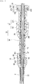
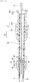
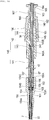
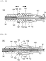
- the operation unit 3 includes a hub 31 having a port 311 through which physiological salt liquid used for performing air bleeding is injected, an outer tube 32 which is provided in the sheath 2 on the proximal side and is fixed thereto, a relay connector 33 (a sheath connection portion) which connects the outer tube 32 and the sheath 2, a second connector 35 which can be connected to and disconnected from the outer tube 32 on the proximal side, and an inner tube 34 which is fixed to the hub 31 on the distal side and moves relatively with respect to the outer tube 32 inside the outer tube 32 in accordance with a movement of the hub 31.
- the outer tube 32 includes an outer tube main body 36 which is fixed to the relay connector 33 on the distal side, and a unit connector 37 which is fixed to the outer tube main body 36 on the proximal side and can be connected to and disconnected from the second connector 35.
- a tapered slope portion 361 which slopes toward the axial center as being closer to the distal side is formed on an inner circumferential surface fixed to the relay connector 33 on the distal side.
- the hub 31 holds the drive shaft 42 and the inner tube 34.
- the drive shaft 42 slides in the axial direction inside the operation unit 3 and the sheath 2 in association with the inner tube 34.
- the end portion of the inner tube 34 on the distal side arrives at the vicinity of the end portion of the outer tube 32 on the distal side, that is, the vicinity of the relay connector 33. Then, in the aforementioned state, the transducer unit 41 is positioned in the vicinity of the distal end of the sheath tube 22 of the sheath 2.
- a protective tube 67 has been fixed to the inner circumferential surface through which the drive shaft 42 in the distal portion of the inner tube 34 passes.
- the drive shaft 42 is accommodated inside the protective tube 67, which extends toward the distal side further than the inner tube 34 and is slidable in the axial direction inside the outer tube 32 and inside the sheath tube 22. Therefore, when the inner tube 34 is thrust into the outer tube 32, the protective tube 67 is thrust in a direction of being thrust. Then, the drive shaft 42 which is positioned inside the outer tube 32 on the distal side from the inner tube 34 is covered with the protective tube 67 inside the outer tube 32.
- the drive shaft 42 is in a state of being accommodated inside the protective tube 67 of which the inner diameter is smaller than the outer tube 32. Therefore, when the inner tube 34 is thrust into or drawn out of the outer tube 32, the drive shaft 42 is held by the protective tube 67, and the protective tube 67 can prevent the drive shaft 42 from being bent or the like.
- the protective tube 67 may be a tubular body which is impermeable to liquid and is formed with a wall surface having no openings, instead of the coil or the like which allows water to permeate.
- the protective tube 67 can guide physiological salt liquid, which is supplied through the port 311 of the hub 31, to the inside of the sheath tube 22 without allowing the physiological salt liquid to flow into the outer tube 32.
- the material of the protective tube 67 for example, polyimide, blade containing polyimide, PTFE, polyethylene, polyamide, or the like can be applied. However, the material is not limited thereto.
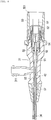
- the unit connector 37 includes a unit connector main body 371 and a cover member 63.
- a tapered female connector 372 (a first connector) and a male screw portion 376 which is formed in the outer circumference of the female connector 372 have been formed in the unit connector main body 371 on the proximal side.
- the second connector 35 is connected to a connection portion main body 351 and the female connector 372 of the unit connector 37 in a liquid-tight manner, and includes a disconnectably tapered male connector 352 and a female screw portion 356 which is formed in the outer circumference of the male connector 352.
- the female connector 372 and the male connector 352 comprise a luer taper structure in which a predetermined gradient is formed so as to exhibit high sealing performance.
- the unit connector main body 371 and the second connector 35 are fixed to each other by screwing the male screw portion 376 into the female screw portion 356 so that it is possible to firmly maintain a state where the male connector 352 is connected to the female connector 372 in a liquid-tight manner.
- the female connector 372 and the male connector 352 have a lock-type luer taper structure comprising a screw-type lock mechanism which is configured to include the male screw portion 376 and the female screw portion 356.
- a pass-through port 353 which the inner tube 34 slidably penetrates is provided in the second connector 35.
- the pass-through port 353 has the bore diameter smaller than the outer diameter of the stopper 341 so that the stopper 341 cannot pass therethrough.
- the outer tube main body 36 attached to the relay connector 33 is inserted into and fixed to the unit connector main body 371, and the inner tube 34 extending from the hub 31 is inserted into the outer tube main body 36.
- the cover member 63 is combined with the unit connector main body 371, thereby holding the outer tube main body 36.
- the inner tube 34 extending from the hub 31 includes the stopper 341 (the engagement portion) which has been formed at the distal end thereof, even when the hub 31 is pulled to the fullest extent, that is, even when the inner tube 34 is drawn out to the fullest extent from the outer tube 32, the stopper 341 is caught by the end surface of the second connector 35 on the distal side, and thus, the inner tube 34 does not slip out of the unit connector 37.
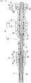
- the relay connector 33 includes an outer tube holding portion 65, an anti-kink protector 66, and a seal member 64.
- the outer tube holding portion 65 holds the outer tube main body 36.
- the end portion of the sheath tube 22 on the proximal side has been joined to the inner surface of the outer tube holding portion 65, and a passage 651 for guiding the drive shaft 42 and the protective tube 67 into the sheath tube 22 through the outer tube 32 has been formed in the end portion thereof.
- the tapered slope portion 361 on the distal side formed in the outer tube main body 36 is substantially the same as the inner diameter of the passage 651, thereby playing a role to smoothly guide a guide wire or the like, which is inserted through the outer tube 32, into the sheath tube 22.
- the slope portion 361 also plays a role to smoothly guide the drive shaft 42 and the protective tube 67 which are inserted through the outer tube 32, into the sheath tube 22.
- the seal member 64 is disposed in the passage 651 of the outer tube holding portion 65 to be in close contact therewith and comprises a through-hole 641 at a central portion thereof.
- the seal member 64 may be embedded in the relay connector 33 or may be fixed thereto by being pinched by the relay connector 33 and the distal portion of the outer tube main body 36.
- the seal member 64 is deformable in a flexible manner. It is preferable that the through-hole 641 is shut and maintains a sealed state when being in a state where nothing is inserted therethrough, is widened by being pressed by the drive shaft 42 or the protective tube 67, and can receive the drive shaft 42 or the protective tube 67.
- the through-hole 641 is formed to have a slit shape.
- the through-hole 641 is a hole which can be in a sealed state. Since the through-hole 641 of the seal member 64 comes into close contact with the outer circumferential surface of the protective tube 67 in a slidable manner, even though physiological salt liquid supplied through the port 311 of the hub 31 passes through the inner tube 34 and the protective tube 67 and flows into the sheath tube 22, the physiological salt liquid does not leak into the outer tube 32 from between the relay connector 33 and the protective tube 67.
- the seal member 64 prevents physiological salt liquid and blood from leaking, even when the protective tube 67 moves all the way to the proximal side in a state where the female connector 372 (the first connector) provided in the unit connector 37, and the second connector 35 are connected to each other (refer to FIG. 4 ), the seal member 64 is provided at a position being in contact with the protective tube 67.
- the material of the seal member 64 for example, natural rubber, silicone rubber, nitrile rubber, fluororubber, or the like can be applied. However, the material is not limited thereto.
- the seal member 64 may have a ring seal structure including an O-ring, an X-ring, or the like. In this case, the seal member 64 may be structured to be provided with a hemostatic device such as a Y-connector and the like at a position on the proximal side (for example, the second connector) from the seal member.
- the hub 31 of the operation unit 3 includes a joint 50, a male connector 51 for driving, a rotor 52, a connection pipe 53, the signal line 54, a hub main body 55, a sealing portion 56, and an anti-kink protector 57.
- the joint 50 includes an opening portion 501 provided on the operator's hand-side of the ultrasound catheter 1, and the male connector 51 for driving and the rotor 52 are disposed inside thereof.
- the male connector 51 for driving can be joined to a female connector 711 for driving included in the external drive apparatus 7 (refer to FIG. 2 ), through the opening portion 501 side of the joint 50. Accordingly, the external drive apparatus 7 and the male connector 51 for driving are mechanically and electrically joined to each other.
- connection pipe 53 is held by the rotor 52 so as not to be able to rotate, and the rotor 52 rotates integrally with the male connector 51 for driving.
- the drive shaft 42 is held by the connection pipe 53 at the end portion opposite to the rotor 52 side in order to transmit rotary motions of the rotor 52 to the drive shaft 42.
- the rotor 52 is interposed between the joint 50 and the hub main body 55, and motions thereof in the axial direction has been restricted.
- the signal line 54 leads to the inside of the connection pipe 53. One end of the signal line 54 has been connected to the male connector 51 for driving, and the other end thereof has been connected to the transducer unit 41 by passing through the inside of the drive shaft 42. An observation result of the transducer unit 41 is transmitted to the external drive apparatus 7 via the male connector 51 for driving, is subjected to suitable processing, and is displayed as an image.
- Physiological salt liquid is injected into the hub main body 55 through the port 311, and the physiological salt liquid is guided into the inner tube 34 without leaking outside. Note that, since the sealing portion 56 comprising an O-ring 58 is installed between the hub main body 55 and the joint 50, physiological salt liquid does not leak onto the opening portion 501 side of the joint 50.
- the inner tube 34 is partially fitted into the hub main body 55, and the anti-kink protector 57 is disposed in the periphery of the inner tube 34 and the hub main body 55.
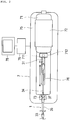
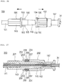
- the external drive apparatus 7 comprises a drive unit 71 which has an external drive source such as a motor and the like built-in so as to rotatively drive the drive shaft, moving means 72 for grasping the drive unit 71 and moving the drive unit 71 in the axial direction by using the motor or the like, and a holding portion 73 which holds a portion of the ultrasound catheter 1 which is fixed at a position.
- the external drive apparatus 7 has been connected to a control unit 79 which controls the drive unit 71 and the moving means 72, and a display portion 78 connected to the control unit 79 displays an image obtained by the transducer unit 41.
- the moving means 72 is a feed mechanism which can fixedly grasp the drive unit 71 and moves the fixedly grasped drive unit 71 forward and rearward along a groove rail 76 on the base 75.
- the drive unit 71 includes the female connector 711 for driving to which the male connector 51 for driving of the ultrasound catheter 1 can be connected, and a joint connection portion 712 which can be connected to the joint 50 of the ultrasound catheter 1. As a result of the connection, the drive unit 71 can transmit and receive a signal with respect to the transducer unit 41 and can rotate the drive shaft 42 at the same time.
- Ultrasound which is transmitted and received by the ultrasound transducer 411 provided in the housing 412 is scanned in a substantially radial direction by transmitting rotary motions of the motor inside the drive unit 71 to the drive shaft 42 and rotating the housing 412 fixed to the distal end of the drive shaft 42, thereby performing ultrasound scanning of the ultrasound catheter 1.
- the ultrasound catheter 1 in its entirety is pulled to the proximal side, and the ultrasound transducer 411 is moved in a longitudinal direction, a 360-degree tomographic image of a surrounding tissue to an arbitrary position inside a blood vessel throughout the axial direction can be obtained by performing scanning.
- a priming operation of filling the inside of the ultrasound catheter 1 with physiological salt liquid is performed before the sheath 2 of the ultrasound catheter 1 is inserted into a lumen. Air inside the ultrasound catheter 1 is removed and air is prevented from entering the inside of a lumen such a blood vessel and the like by performing the priming operation.
- the male connector 352 of the second connector 35 is caused to be in a state of being connected to the female connector 372 of the unit connector 37 in a liquid-tight manner
- the hub 31 is caused to be in a state of being pulled to the fullest extent to the operator's hand-side, that is, in a state where the inner tube 34 is drawn out to the fullest extent from the outer tube 32 (refer to FIG. 4 )
- physiological salt liquid is injected, for example, by applying an injector or the like via an instrument configured to include a tube, a three-way stopcock, an injector, and the like (not illustrated) which are connected to the port 311 of the hub 31.
- the injected physiological salt liquid sequentially passes through the hub 31, the inner tube 34, and the protective tube 67 and fills the inside the sheath 2. Note that, since the space between the relay connector 33 and the protective tube 67 has been sealed by the seal member 64, the physiological salt liquid does not leak into the outer tube 32 from between the relay connector 33 and the protective tube 67.
- the physiological salt liquid comes out through the priming lumen 231 which is formed in the filling liquid inflow and outflow path member 23 (refer to FIG. 3 ) of the sheath 2. In this manner, a filling state of the physiological salt liquid is confirmed. It is possible to remove air inside the ultrasound catheter 1 and to prevent air from entering the inside of a lumen by performing the priming operation.
- the ultrasound catheter 1 is joined to the external drive apparatus 7 which is covered with a sterilized bag or the like (not illustrated) made of polyethylene.
- the joint 50 (refer to FIG. 6 ) of the hub 31 of the ultrasound catheter 1 is connected to the joint connection portion 712 of the drive unit 71.
- a signal can be transmitted and received between the transducer unit 41 and the external drive apparatus 7, and the drive shaft 42 can be rotated at the same time.
- the unit connector 37 fits the holding portion 73, joining processing is completed.
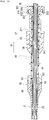
- the hub 31 is thrust into the distal side by moving the drive unit 71 to the distal side along the groove rail 76 on the base 75 so as to cause the inner tube 34 to be in a state of being thrust into the outer tube 32 all the way to the end (refer to FIG. 1 ) .
- the sheath 2 is inserted into a human body, and the insertion stops when the distal end of the sheath 2 passes over a target lesion.
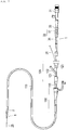
- an introducer sheath 100 is caused to indwell in the femoral artery or the like through the Seldinger's method or the like before the ultrasound catheter 1 is inserted.
- a guiding catheter 110 is inserted into a human body via the introducer sheath 100, and the guiding catheter 110 is caused to indwell at the entrance of the blood vessel of the coronary artery.
- the guide wire 25 is inserted into the blood vessel of the coronary artery to a target place, passing through the guiding catheter 110. Then, while the guide wire 25 which has been inserted into the blood vessel is caused to pass through the guide wire lumen 211 of the ultrasound catheter 1, the sheath 2 of the ultrasound catheter 1 is inserted into the human body through the guiding catheter 110.
- the ultrasound catheter 1 is inserted into the lumen through a valve body 123 of the Y-connector 120 which is connected to the guiding catheter 110 on the proximal side, and the insertion speed of being inserted into the lumen is slowed down at the timing when the marking portion M approaches the vicinity of the valve body 123.
- the ultrasound catheter 1 is inserted along the guide wire 25 to a target lesion to be observed.
- the position of the sheath 2 is fixed.
- a pull-back operation is performed while the drive shaft 42 is rotated by the drive unit 71 so that images of the lumen in the axial direction can be acquired.
- the pull-back operation can be performed by causing the control unit 79 to operate the moving means 72 which is connected to the rear end portion of the ultrasound catheter 1.
- the acquired data is subjected to digital processing performed by the control unit 79, and then, the display portion 78 displays the data as image data.
- the hub 31 is thrust into the distal side again, and the imaging core 4 is caused to move forward. Thereafter, the ultrasound catheter 1 is operated to be pulled out of the inside of the lumen.
- the ultrasound catheter 1 since the ultrasound catheter 1 has the rapid-exchange structure, there is a possibility of an occurrence of a phenomenon, that is, so-called "wire separation" in which the guide wire 25 is warped and is separated from the ultrasound catheter 1 as the ultrasound catheter 1 is pulled to the proximal side.
- wire separation in which the guide wire 25 is warped and is separated from the ultrasound catheter 1 as the ultrasound catheter 1 is pulled to the proximal side.
- the ultrasound catheter 1 is used in order to confirm a stent which indwells inside the lumen, for example, there is a concern that the ultrasound catheter 1 or the guide wire 25 is caught by a strut of the stent and the ultrasound catheter 1 is unlikely to be pulled out.
- an operator separates the male screw portion 376 from the female screw portion 356 by rotating the second connector 35 of the ultrasound catheter 1, and thus, the male connector 352 provided in the second connector 35 can be disconnected from the female connector 372 provided in the unit connector 37.
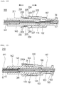
- the hub 31 in the entirety of the external drive apparatus 7 is moved to the proximal side while being in a state where the outer tube 32 is grasped and fixed, the inner tube 34, the protective tube 67, the imaging core 4, and the second connector 35 move to the proximal side together with the hub 31 as illustrated in FIGS. 8 and 9 .
- the protective tube 67 and the imaging core 4 are pulled out of the sheath 2 and the outer tube 32 as illustrated in FIG. 10 .
- the seal member 64 prevents blood from leaking via the lumen of the sheath 2, thereby improving the safety, and blood does not leak on the hand-side of an operator, thereby improving the operability as well.
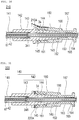
- a wire W which is a separately prepared guide wire or the like is inserted into the lumen in which the imaging core 4 has been disposed.
- the tapered slope portion 361 is formed on the inner circumferential surface of the outer tube main body 36 on the distal side and the slope portion 361 on the distal side is substantially the same as the inner diameter of the passage 651, the wire W which is inserted through the outer tube 32 can be smoothly inserted into the sheath tube 22.
- the seal member 64 allows the wire W to be inserted therethrough and prevents blood from leaking via the lumen of the sheath 2.
- the outer tube 32 which includes the female connector 372 (the first connector) is provided in the sheath 2 on the proximal side.
- the second connector 35 which can be connected to and disconnected from the female connector 372 is provided in the outer tube 32 on the proximal side.
- the inner tube 34 which moves relatively to the outer tube 32 inside the outer tube 32 in accordance with a movement of the hub 31 is provided.
- the stopper 341 (the engagement portion) which cannot pass through the inner side of the second connector 35 is provided in the distal portion of the inner tube 34. Therefore, in a state where the second connector 35 is connected to the outer tube 32, the inner tube 34 can be held so as not to come out due to the stopper 341 caught by the second connector 35. Furthermore, the second connector 35 is disconnected from the outer tube 32, and the hub 31 is moved to the proximal side. Thus, the imaging core 4 can be pulled out of the sheath 2.
- the ultrasound catheter 1 is provided with the protective tube 67 which protrudes toward the distal side further than the inner tube 34, accommodates the drive shaft 42, can be inserted into the outer tube 32 and the sheath 2, and is pulled out of the outer tube 32 together with the hub 31 and the inner tube 34 as the second connector 35 is disconnected from the female connector 372 (the first connector) . Therefore, when the inner tube 34 is thrust into or drawn out of the outer tube 32, the drive shaft 42 can be prevented from bending or the like by the protective tube 67, and when the imaging core 4 is pulled out of the sheath 2, the protective tube 67 is pulled out together with the hub 31 and the inner tube 34.
- the wire W when the wire W is inserted into the lumen in which the imaging core 4 has been disposed, there is no need to insert the wire W through the protective tube 67, thereby improving the operability.
- the thin protective tube 67 does not protrude from the outer tube 32 side through which the wire W is inserted, the safety is improved when the wire W is inserted therethrough.
- the second connector 35 is provided in the outer tube 32 on the proximal side instead of the distal side and is disposed being away from the Y-connector 120 during the operation. Therefore, the second connector 35 does not interfere with the guide wire 25 which has led from the Y-connector 120, and the guide wire 25 is easily controlled even when the ultrasound catheter 1 is operated, thereby improving the operability of the guide wire 25 and the ultrasound catheter 1.
- the relay connector 33 comes into contact with the outer circumferential surface of the protective tube 67 in a slidable manner, and there is provided the seal member 64 that shuts the passage 651 through which the protective tube 67 is inserted as the protective tube 67 and the imaging core 4 are pulled out, when the protective tube 67 and the imaging core 4 are completely pulled out, the through-hole 641 of the seal member 64 is shut and is in a sealed state as illustrated in FIG. 11 .
- the outer tube 32 is provided in the relay connector 33 on the proximal side on which the seal member 64 is provided, blood leaking from the seal member 64 does not reach the outside unless the blood passes through the outer tube 32 further. Therefore, blood is prevented from leaking via the lumen of the sheath 2, thereby improving the safety, and blood does not leak on the hand-side of an operator, thereby improving the operability as well.
- the protective tube 67 since the protective tube 67 has been fixed to the inner tube 34, the protective tube 67 can be moved in accordance with a movement of the inner tube 34.
- the protective tube 67 is the tubular body which is impermeable to liquid, blood, physiological salt liquid, or the like circulating the inside of the protective tube 67 does not leak into the outer tube 32 via the protective tube 67.
- priming liquid such as physiological salt liquid and the like
- air remaining inside the protective tube 67 can be reduced, it is possible to shorten the preparation time when in use.
- blood, physiological salt liquid, or the like does not leak into the outer tube 32, there is no need to provide the seal member between the outer tube 32 and the inner tube 34.
- liquid such as blood, physiological salt liquid, and the like is prevented from leaking into the outer tube 32, the liquid is more reliably prevented from leaking out further than the outer tube 32, and since the liquid does not leak on the hand-side of an operator, thereby improving the operability as well.
- the slope portion 361 which slopes toward the axial center as being closer to the distal side has been formed on the inner circumferential surface of the outer tube 32; the wire W, the imaging core 4, the protective tube 67, and the like which are inserted through the outer tube 32 can be smoothly guided into the sheath tube 22 of which the inner diameter is smaller than the outer tube 32.
- the ultrasound catheter 1 in the first embodiment can be disconnected by the second connector 35, it is possible to cause the sheath 2 and the outer tube 32 side which is inserted into the lumen and is able to be manufactured at low costs to be disposable, and it is possible to cause the hub 31 and the inner tube 34 side comprising the imaging core 4 which are expensive to be reusable.
- the sheath 2 side can be disconnected by the second connector 35, it is possible to replace the sheath with another one which is different in thickness, length of the monorail, and the like, for example, in accordance with the usage condition of the ultrasound catheter 1.
- the stopper 341 (the engagement portion) of the ultrasound catheter 1 in the first embodiment has been formed in the distal portion of the inner tube 34 as a portion of the inner tube 34.
- the engagement portion does not need to be formed as a portion of the inner tube.
- an engagement portion 81 formed with a member which is different from the inner tube 80 and the protective tube 67 may be provided in the distal portion of an inner tube 80.
- the engagement portion 81 can be prohibited from passing through the inner side of the second connector 35, and in a state where the second connector 35 is connected to the outer tube 32, the inner tube 80 can be held so as not to come out due to the engagement portion 81 caught by the second connector 35.
- an engagement portion 84 may be formed as a portion of a protective tube 83 instead of an inner tube 82. Even in such a configuration, the engagement portion 84 can be prohibited from passing through the inner side of the second connector 35.
- an engagement portion 87 may be formed as a portion of a protective tube 86 covering an inner tube 85. Even in such a configuration, the engagement portion 87 can be prohibited from passing through the inner side of the second connector 35.
- an inner tube 88, a protective tube 89, and an engagement portion 90 may be integrally formed as the same member. Even in such a configuration, the engagement portion 90 can be prohibited from passing through the inner side of the second connector 35.
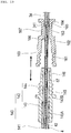
- an ultrasound catheter 130 in a second embodiment of the present invention is different from the ultrasound catheter 1 in the first embodiment in configurations of an outer tube 140 which is provided in the sheath 2 on the proximal side, a relay connector 150 (the sheath connection portion) which connects the outer tube 140 and the sheath 2 to each other, and a unit connector proximal portion 160 (the second connector) which can be connected to and disconnected from the outer tube 140 on the proximal side.
- the same reference numerals and signs are applied to the portions having the same function as those in the first embodiment, and descriptions thereof will be omitted.
- the outer tube 140 comprises an outer tube main body 141 of which the distal portion is connected to the relay connector 150, and a substantially tubular unit connector distal portion 142 to which a proximal portion of the outer tube main body 141 is fixed.
- the outer tube main body 141 is formed with a tubular body of which the inner diameter and the outer diameter are uniform along an axial line direction.
- the unit connector distal portion 142 comprises an outer tube fixing portion 143 to which the outer tube main body 141 is fixed, and a first connector 144 to which the unit connector proximal portion 160 is connected.
- the first connector 144 comprises a male screw portion 145 which is formed on the outer circumferential surface, and a tapered male connector 146.
- the male connector 146 has been formed on the proximal side from the male screw portion 145.
- the male screw portion 145 has been formed in a shape of a trapezoid-threaded screw in which the apex portions of a screw thread are cut to be flat and a cross section thereof exhibits a trapezoid.
- the pitch of the screw thread in the male screw portion 145 is 2 mm. However, the pitch is not limited thereto.
- the male screw portion 145 is formed to have one screw thread. However, the male screw portion 145 may be formed to have two or more screw threads.
- An outer tube accommodation portion 143A in which the outer tube main body 141 fixedly fits has been formed on the inner circumferential surface of the outer tube fixing portion 143, and a first inner diameter portion 143B having the inner diameter which is greater than the inner diameter of the outer tube main body 141 and smaller than the outer diameter of the same has been formed in the outer tube accommodation portion 143A on the proximal side.
- the inner tube 34 is movable together with the stopper 341 inside the first inner diameter portion 143B and the outer tube main body 141.
- the unit connector proximal portion 160 (the second connector) has been formed to have a substantially tubular shape.
- the female connector 162 has been formed on the proximal side from the female screw portion 161.
- the second inner diameter portion 163 has been formed on the proximal side from the female connector 162, and the pass-through port 164 has been formed on the proximal side from the second inner diameter portion 163.
- a step difference portion 165 of which the inner diameter varies has been formed between the second inner diameter portion 163 and the pass-through port 164.
- the pass-through port 164 has an inner diameter smaller than the outer diameter of the stopper 341, the stopper 341 cannot pass therethrough.
- a guidance portion 166 of which the inner diameter is widened in a tapered manner toward the distal side has been formed in the second inner diameter portion 163 on the distal side.
- a clamp portion 167 which is held (clamped) by the holding portion 73 (refer to FIG. 2 ) of the external drive apparatus 7 has been formed on the outer circumferential surface of the unit connector proximal portion 160 on the proximal side.
- the female connector 162 and the male connector 146 comprise a luer taper structure in which a predetermined gradient is formed so as to exhibit high fitting force.
- the unit connector distal portion 142 and the unit connector proximal portion 160 are fixed to each other on account of friction force generated by screwing the male screw portion 145 of the unit connector distal portion 142 into the female screw portion 161 of the unit connector proximal portion 160, and thus, a state where the male connector 146 is connected with the female connector 162 can be firmly maintained.
- the gradient of the female connector 162 and the male connector 146 can be set to 6/100 which is defined by the ISO standard while expecting strong fitting force (friction force) utilizing a wedge effect.
- the gradient is not limited thereto as long as a wedge effect can be utilized.
- the male screw portion 145 is the trapezoid-threaded screw, when the tapered male connector 146 and the female connector 162 are caused to fit as wedges, it is possible to expect sufficient strength.
- the male screw portion 145 is the trapezoid-threaded screw, the outer diameter of the male screw portion 145 can be decreased, and the outer diameter of the unit connector proximal portion 160 in which the female screw portion 161 is formed can be decreased.
- the male screw portion 145 is formed to have one screw thread. However, if the male screw portion 145 is formed to have two or more screw threads, the male screw portion 145 can be disconnected from the female screw portion 161 by the small number of rotations, and thus, it is possible to improve working properties.
- the male screw portion 145 is the trapezoid-threaded screw, a lead angle becomes less than a contact angle. Therefore, it is possible to expect a high locking effect by utilizing self-locking performance exhibiting high fixing power.
- the inner tube 34 extending from the hub 31 includes the stopper 341 (the engagement portion) which has been formed at the distal end thereof, even when the hub 31 is pulled to the fullest extent, that is, even when the inner tube 34 is drawn out to the fullest extent from the outer tube 140, the stopper 341 is caught by the step difference portion 165 of the unit connector proximal portion 160, and thus, the inner tube 34 can be prevented from slipping out of the unit connector proximal portion 160.
- the relay connector 150 includes a substantially tubular outer tube holding portion 151 which holds the outer tube, a spacer 152 which is disposed inside the outer tube holding portion 151, and a seal member 153.
- a passage 154 which guides the drive shaft 42 and the protective tube 67 into the sheath tube 22 from the outer tube 140 has been formed inside the outer tube holding portion 151.
- the passage 154 has been configured to have a sheath accommodation portion 154A to which the sheath tube 22 is fixed, a seal member accommodation portion 154B which accommodates the seal member 153, and a spacer accommodation portion 154C which accommodates the spacer 152.
- the sheath accommodation portion 154A, the seal member accommodation portion 154B, and the spacer accommodation portion 154C have been disposed side by side in the proximal end direction from the distal side.
- the seal member accommodation portion 154B has the inner diameter greater than that of the sheath accommodation portion 154A
- the spacer accommodation portion 154C has the inner diameter greater than that of the seal member accommodation portion 154B.
- the spacer 152 is a member which is disposed between the outer tube holding portion 151 and the outer tube main body 141.
- the spacer 152 comprises a tubular spacer distal portion 155 which is fixed to the outer tube holding portion 151, and a spacer proximal portion 156 which is disposed in the spacer distal portion 155 on the proximal side and of which the outer circumferential surface is covered with the outer tube main body 141.
- the spacer proximal portion 156 of which the outer circumferential surface is covered with the outer tube main body 141 has been joined to the outer tube main body 141, and a slope portion 156A which is continuously connected to the inner circumferential surface of the spacer distal portion 155 and of which the inner diameter is widened in the proximal end direction in a tapered manner has been formed on the inner circumferential surface thereof.
- the inner circumferential surface of the spacer distal portion 155 plays a role to perform positioning (axis aligning) of the protective tube 67 at the center of the relay connector 150
- the outer circumferential surface of the spacer proximal portion 156 plays a role to perform positioning (axis aligning) of the outer tube main body 141 at the center of the relay connector 150.
- a space is formed with the spacer accommodation portion 154C, and the space has been uniformly filled with an adhesive 157.
- the slope portion 156A of the spacer proximal portion 156 plays a role to smoothly guide a guide wire or the like, which is inserted through the outer tube 140, into the sheath tube 22.
- the slope portion 156A also plays a role to smoothly guide the drive shaft 42 and the protective tube 67, which are inserted through the outer tube 140, into the sheath tube 22.
- the spacer 152 has been formed to have the end surface on the distal side to be wider than the end surface of the outer tube main body 141 on the distal side.
- the spacer 152 plays a role to hold the seal member 153 and plays a role to maintain favorable sealing efficiency of the seal member 153 by preventing the seal member 153 from jumping out in the proximal end direction.
- the spacer 152 plays a role to hold the seal member 153 and plays a role to maintain favorable sealing efficiency of the seal member 153 by preventing the seal member 153 from jumping out in the proximal end direction.
- the outer tube main body 141 comes into contact with the seal member 153.
- the seal member 153 is likely to be deformed.
- deformation of the seal member 153 is prevented by providing the spacer 152, and thus, it is possible to maintain favorable sealing efficiency.
- the slope portion 361 is formed on the inner side surface of the outer tube main body 36.
- the spacer 152 in which the slope portion 156A is formed as in the second embodiment is provided as a member separated from the outer tube main body 141, even when the outer tube main body is thin and it is difficult to form a slope portion in the outer tube main body itself, the slope portion 156A can be easily formed by utilizing the spacer 152.
- the seal member 153 is the ring seal structure including the O-ring, the X-ring, or the like.
- the seal member 153 is disposed while being in close contact with the seal member accommodation portion 154B of the outer tube holding portion 151 and comprises a through-hole 153A in a central portion.
- the seal member 153 is deformable in a flexible manner.
- the through-hole 153A is widened by being pressed by the protective tube 67 and can receive the drive shaft 42 and the protective tube 67.
- the material of the seal member 153 for example, natural rubber, silicone rubber, nitrile rubber, fluororubber, or the like can be applied. However, the material is not limited thereto.
- the ultrasound catheter 130 in the second embodiment is applied by being joined to the external drive apparatus 7.
- the joint 50 (refer to FIG. 6 ) of the hub 31 of the ultrasound catheter 130 is connected to the joint connection portion 712 of the drive unit 71.
- a signal can be transmitted and received between the transducer unit 41 and the external drive apparatus 7, and the drive shaft 42 can be rotated at the same time.
- the clamp portion 167 of the unit connector proximal portion 160 fits the holding portion 73, joining processing is completed.
- the clamp portion 167 which fits the holding portion 73 is provided in the unit connector proximal portion 160 (the second connector) instead of the unit connector distal portion 142.
- the unit connector proximal portion 160 When the clamp portion 167 is provided in the unit connector distal portion 142, the unit connector proximal portion 160 is disposed between the holding portion 73 of the external drive apparatus 7 and the joint connection portion 712. Therefore, in order to maintain the movable distance to be long for the inner tube 34 with respect to the outer tube 140, there may be a need to shorten the length of the anti-kink protector 57 which is attached to the hub main body 55. However, as the clamp portion 167 is provided in the unit connector proximal portion 160, the anti-kink protector 57 is unlikely to be required to shorten the length thereof, and thus, it is possible to effectively exhibit the effect of the anti-kink protector 57.
- the male screw portion 145 of the unit connector distal portion 142 is positioned to be arranged in the axial direction with respect to the male connector 146 instead of outward in the radial direction
- the female screw portion 161 of the unit connector proximal portion 160 is positioned to be arranged in in the axial direction with respect to the female connector 162 instead of outward in the radial direction, it is possible to decrease the outer diameter of the unit connector.
- the drive unit 71 is moved to the distal side along the groove rail 76 on the base 75, and the inner tube 34 is caused to be in a state of being thrust into the outer tube 140 all the way to the end. Then, the sheath 2 is inserted into a human body, and the insertion stops when the distal end of the sheath 2 passes over a target lesion.
- the pull-back operation is performed while the drive shaft 42 is rotated by the drive unit 71 so that images of the lumen in the axial direction are acquired.
- the stopper 341 which is formed in the inner tube 34 can move into the first inner diameter portion 143B from the outer tube main body 141 without being caught. Accordingly, movement of the ultrasound transducer 411 becomes smooth, and no disturbance such as jumping and the like occurs in an image. Thus, it is possible to acquire favorable images.
- the stopper 341 which is formed in the inner tube 34 can move to the second inner diameter portion 163 through the guidance portion 166 without being caught. Accordingly, movement of the ultrasound transducer 411 becomes smooth, and no disturbance such as jumping and the like occurs in an image. Thus, it is possible to acquire favorable images.
- the hub 31 is thrust into the distal side again, and the imaging core 4 is caused to move forward.
- the stopper 341 since the outer diameter of the outer circumferential surface of the stopper 341 in the inner tube decreases in a distal end direction, the stopper 341 can smoothly move without being caught inside the unit connector.
- the ultrasound catheter 130 is operated to be pulled out of the inside of the lumen.
- an operator rotates the unit connector proximal portion 160 of the ultrasound catheter 130 with respect to the unit connector distal portion 142, and thus, it is possible to separate the male screw portion 145 from the female screw portion 161 and to disconnect the male connector 146 from the female connector 162.
- the male screw portion 145 is the trapezoid-threaded screw, and the screw thread has a long pitch, the male screw portion 145 can be separated from the female screw portion 161 by the small number of rotations. Therefore, for example, it is possible to perform prompt measures in case of emergency such as an occurrence of "trapping" described above, for example, thereby enhancing working properties.
- the hub 31 in the entirety of the external drive apparatus 7 is moved to the proximal side while being in a state where the outer tube 140 is grasped and fixed, the inner tube 34, the protective tube 67, the imaging core 4, and the unit connector proximal portion 160 move to the proximal side together with the hub 31 as illustrated in FIG. 19 .
- the protective tube 67 and the imaging core 4 are pulled out of the sheath 2 and the outer tube 140.
- the wire W which is a separately prepared guide wire or the like is inserted into the lumen in which the imaging core 4 has been disposed, through the opening portion in the unit connector distal portion 142 on the proximal side.
- the tapered slope portion 156A has been formed on the inner circumferential surface of the spacer 152, the wire W inserted through the outer tube 140 can be smoothly inserted into the sheath tube 22.
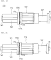
- An ultrasound catheter 170 according to a third embodiment is different from the second embodiment in only the point that a structure for preventing a unit connector distal portion 171 and a unit connector proximal portion 172 from being loosened is provided.
- the same reference numerals and signs are applied to the portions having the same function as those in the first and second embodiments, and descriptions thereof will be omitted.
- a plurality of teeth 173 arranged in have been formed on a proximal end surface 171A of the outer tube fixing portion 143 of a unit connector distal portion 171 in a circumferential direction, and at least one convex portion 174 which can mesh with the teeth 173 of the proximal end surface 171A has been formed on a distal end surface 172A of the unit connector proximal portion 172, that is, the distal end surface 172A facing the proximal end surface 171A of the outer tube fixing portion 143.
- the convex portion 174 of the distal end surface 172A of the unit connector proximal portion 172 meshes with any one of the teeth 173 of the proximal end surface 171A of the outer tube fixing portion 143 so as to be caught thereby in a state where the unit connector proximal portion 172 is connected to the unit connector distal portion 171. Therefore, in order to loosen connection between the unit connector distal portion 171 and the unit connector proximal portion 172, there is a need to have rotary force sufficient for the convex portion 174 to ride over the teeth 173.
- connection between the unit connector distal portion 171 and the unit connector proximal portion 172 can be prevented from being loosened due to unexpected force, thereby improving reliability and safety.
- the force for preventing the unit connector distal portion 171 and the unit connector proximal portion 172 from being loosened can be suitably set based on slope angles with respect to the distal end surface 172A and the proximal end surface 171A of the teeth 173 and the convex portion 174.
- slope angles with respect to the distal end surface 172A and the proximal end surface 171A of the teeth 173 and the convex portion 174 For example, as described in the modification example illustrated in FIG. 21 , in a case of significant slope angles of portions with which teeth 175 and a convex portion 176 come into contact when the unit connector distal portion 171 and the unit connector proximal portion 172 are rotated in a direction to be loosened, significant force is necessary in order to loosen the connection. However, it is possible to improve the reliability and the safety.
- the plurality of teeth 173 have been formed in the unit connector distal portion 171 and at least one convex portion 174 has been formed in the unit connector proximal portion 172.
- a convex portion may be formed in the unit connector distal portion, and teeth may be formed in the unit connector proximal portion.
- the above-described ultrasound catheter 170 according to the third embodiment is provided with the male connector 146 and the female connector 162 for generating fitting force (friction force) by utilizing a wedge effect.
- the structure (the teeth 173 and the convex portion 174) for preventing the unit connector distal portion 171 and the unit connector proximal portion 172 from being loosened, unless it is intended to maintain higher fitting force in a fitting portion, the male connector 146 and the female connector 162 do not need to be provided.
- An ultrasound catheter 180 according to a fourth embodiment is different from the second embodiment in only the point that a structure for preventing a unit connector distal portion 181 and a unit connector proximal portion 182 from being loosened is provided.
- the same reference numerals and signs are applied to the portions having the same function as those in the first and second embodiments, and descriptions thereof will be omitted.
- an annular convex portion 183 extending in in the circumferential direction has been formed on the outer circumferential surface of the outer tube fixing portion 143 of the unit connector distal portion 181, and an annular joining portion 184 extending in the distal end direction and covering the outside surface of the annular convex portion 183 has been formed in the unit connector proximal portion 182 on the distal side.
- An engagement portion 185 protruding toward the central axis so as to be caught by the annular convex portion 183 has been formed in the annular joining portion 184 on the distal side from the annular convex portion 183.
- the engagement portion 185 engages with the annular convex portion 183 in a state where the male screw portion 145 is screwed into the female screw portion 161 and the unit connector proximal portion 182 is connected to the unit connector distal portion 181.
- perforation-like holes 186 arranged in the circumferential direction have been formed in the annular joining portion 184 on the proximal side from the engagement portion 185.
- a breakage portion 187 has been formed between the adjacent holes 186.
- the engagement portion 185 engages with the annular convex portion 183 in a state where the male screw portion 145 is screwed into the female screw portion 161 and the unit connector proximal portion 182 is connected to the unit connector distal portion 181. Therefore, for example, in a case of being erroneously in contact with the unit connector during a manipulation, connection between the unit connector distal portion 181 and the unit connector proximal portion 182 can be prevented from being erroneously loosened due to unexpected force, thereby improving the reliability and the safety.
- the above-described ultrasound catheter 180 according to the fourth embodiment is provided with the male connector 146 and the female connector 162 for generating fitting force (friction force) by utilizing a wedge effect.
- the structure (the engagement portion 185 and the annular convex portion 183) for preventing the unit connector distal portion 181 and the unit connector proximal portion 182 from being loosened, unless it is intended to maintain higher fitting force in the fitting portion, the male connector 146 and the female connector 162 do not need to be provided.
- An ultrasound catheter 190 according to a fifth embodiment is different from the second embodiment in only the point that a structure for preventing a unit connector distal portion 191 and a unit connector proximal portion 192 from being loosened is provided, and no female screw portion or male screw portion to be screwed to each other is provided.
- the same reference numerals and signs are applied to the portions having the same function as those in the first and second embodiments, and descriptions thereof will be omitted.
- the ultrasound catheter 190 As illustrated in FIG. 25 , at least one convex portion 193 (two in the present embodiment) extending in the proximal end direction from the outer tube fixing portion 143 of the unit connector distal portion 191 has been formed, and a concave portion 194 which the convex portion 193 can fit has been formed in the unit connector proximal portion 192 on the distal side.
- a first engagement claw 195 has been formed at the distal end of the convex portion 193, and a second engagement claw 196 by which the first engagement claw 195 is caught has been formed inside the concave portion 194.
- the convex portion 193 fits the concave portion 194, and the first engagement claw 195 and the second engagement claw 196 engage with each other.
- the first engagement claw 195 engages with the second engagement claw 196. Therefore, for example, in a case of being erroneously in contact with the unit connector during a manipulation, connection between the unit connector distal portion 191 and the unit connector proximal portion 192 can be prevented from being erroneously loosened due to unexpected force, thereby improving the reliability and the safety.
- the unit connector distal portion 191 and the unit connector proximal portion 192 can be coaxially connected to each other.
- the unit connector distal portion 191 and the unit connector proximal portion 192 are moved in a direction of being separated from each other, the first engagement claw 195 and the second engagement claw 196 are disengaged from each other due to deformation or destruction as illustrated in FIG. 26 , and thus, the unit connector distal portion 191 and the unit connector proximal portion 192 can be disconnected from each other.
- the above-described ultrasound catheter 190 according to the fifth embodiment is provided with the male connector 146 and the female connector 162 for generating fitting force (friction force) by utilizing a wedge effect.
- the structure (the first engagement claw 195 and the second engagement claw 196) for preventing the unit connector distal portion 191 and the unit connector proximal portion 192 from being loosened, unless it is intended to maintain higher fitting force in the fitting portion, the male connector 146 and the female connector 162 do not need to be provided.
- An ultrasound catheter 200 according to a sixth embodiment is different from the second embodiment in only the point that a structure for preventing a unit connector distal portion 201 and a unit connector proximal portion 202 from being loosened is provided, and no female screw portion or male screw portion to be screwed to each other is provided.
- the same reference numerals and signs are applied to the portions having the same function as those in the first and second embodiments, and descriptions thereof will be omitted.
- At least one convex portion 203 (two in the present embodiment) extending in the proximal end direction from the outer tube fixing portion 143 of the unit connector distal portion 201 has been formed, and a turned-back portion 204 has been formed so as to be turned back from the protruding distal end of the convex portion 203.
- a first engagement claw 205 protruding outward in the radial direction and a press portion 206 for moving the first engagement claw 205 backward by being pressed by an operator so as to warp the turned-back portion 204 have been formed in the turned-back portion 204.
- a concave portion 207 which the convex portion 203 can fit has been formed in the unit connector proximal portion 202 on the distal side, and a second engagement claw 208 by which the first engagement claw 205 is caught has been formed inside the concave portion 207.
- the convex portion 203 fits the concave portion 207, and the first engagement claw 205 and the second engagement claw 208 engage with each other.
- the first engagement claw 205 engages with the second engagement claw 208. Therefore, for example, in a case of being erroneously in contact with the unit connector during a manipulation, connection between the unit connector distal portion 201 and the unit connector proximal portion 202 can be prevented from being erroneously loosened due to unexpected force, thereby improving the reliability and the safety.
- the convex portion 203 fits the concave portion 207, the unit connector distal portion 201 and the unit connector proximal portion 202 can be coaxially connected to each other.
- the above-described ultrasound catheter 200 according to the sixth embodiment is provided with the male connector 146 and the female connector 162 for generating fitting force (friction force) by utilizing a wedge effect.
- the structure (the first engagement claw 205 and the second engagement claw 208) for preventing the unit connector distal portion 201 and the unit connector proximal portion 202 from being loosened, unless it is intended to maintain higher fitting force in the fitting portion, the male connector 146 and the female connector 162 do not need to be provided.
- An ultrasound catheter 210 according to a seventh embodiment is different from the second embodiment in only the point that a structure for preventing the unit connector distal portion 142 and the unit connector proximal portion 160 from being loosened has been added.
- the same reference numerals and signs are applied to the portions having the same function as those in the first and second embodiments, and descriptions thereof will be omitted.
- the outer tube fixing portion 143 of the unit connector distal portion 142 and the unit connector proximal portion 160 have been joined to each other by a tape 210A which is provided with a glue or an adhesive on one surface side in a peelable manner.
- the material of the tape 210A is not particularly limited as long as the material can be peelably pasted.
- the above-described ultrasound catheter 210 according to the seventh embodiment is provided with the male connector 146 and the female connector 162 for generating fitting force (friction force) by utilizing a wedge effect.
- An ultrasound catheter 220 according to an eighth embodiment is different from the second embodiment in only the point that the structure for preventing the unit connector distal portion 142 and the unit connector proximal portion 160 from being loosened has been added.
- the same reference numerals and signs are applied to the portions having the same function as those in the first and second embodiments, and descriptions thereof will be omitted.
- the outer tube fixing portion 143 of the unit connector distal portion 142 and the unit connector proximal portion 160 have been joined to each other by an adhesive 220A.
- the material of the adhesive 220A is not particularly limited as long as the material can be peelably bonded. In this manner, the unit connector distal portion 142 and the unit connector proximal portion 160 have been bonded to each other by the adhesive 220A.
- connection between the unit connector distal portion 142 and the unit connector proximal portion 160 can be prevented from being erroneously loosened due to unexpected force, thereby improving the reliability and the safety.
- the adhesive 220A is caused to peel off, and thus, the unit connector distal portion 142 and the unit connector proximal portion 160 can be disconnected from each other.
- the above-described ultrasound catheter 220 according to the eighth embodiment is provided with the male connector 146 and the female connector 162 for generating fitting force (friction force) by utilizing a wedge effect.
- the present invention is not limited to only the above-described embodiments, and various changes can be made by those skilled in the art within the technical ideas of the present invention.
- an OCT catheter such as an optical coherence tomography diagnosis apparatus, an optical frequency domain imaging diagnosis apparatus, and the like utilizing light; an endoscope system; and the like.
- the present invention can be applied to all catheters as long as the catheter has a tubular body such as the catheter and the like for performing mechanical drive, for example, a catheter which is used in directional coronary atherectomy (DCA). Therefore, in the present embodiment, liquid fills the inside the lumen of the sheath 2 in which the imaging core 4 is accommodated.
- DCA directional coronary atherectomy
- the protective tube 67 has been fixed to the inner circumferential surface of the inner tube 34.
- the portion to which the protective tube is fixed is not limited to the inner circumferential surface of the inner tube 34.
- a protective tube 167 may be fixed to the hub 31 as described in the modification example illustrated in FIGS. 32 and 33 .
- the protective tube may be integrally formed with the inner tube or the hub.
- the tapered slope portion 361 which slopes toward the axial center as being closer to the distal side has been formed on the inner circumferential surface of the outer tube main body 36 on the distal side fixed to the relay connector 33.
- a tapered slope portion 681 which slopes toward the axial center as being closer to the distal side may be formed in a relay connector 68 to which the outer tube main body is fixed.
- the through-hole 641 of the seal member 64 is in a sealed state by the elastic force of itself when the drive shaft 42 and the protective tube 67 are pulled out.
- a mechanism for pressing the seal member may be provided so as to obtain a structure having the through-hole to be in a sealed state by compressing and deforming the seal member.
- the female connector 372 has been provided on the outer tube 32 side, and the male connector 352 has been provided on the second connector 35 side.
- the male connector may be provided on the outer tube 32 side, and the female connector may be provided on the second connector 35 side.
- the structure of connection may be a screw type or an insertion type instead of the luer taper structure.
Landscapes
- Health & Medical Sciences (AREA)
- Life Sciences & Earth Sciences (AREA)
- Heart & Thoracic Surgery (AREA)
- Animal Behavior & Ethology (AREA)
- General Health & Medical Sciences (AREA)
- Public Health (AREA)
- Veterinary Medicine (AREA)
- Engineering & Computer Science (AREA)
- Biomedical Technology (AREA)
- Biophysics (AREA)
- Pulmonology (AREA)
- Anesthesiology (AREA)
- Hematology (AREA)
- Pathology (AREA)
- Surgery (AREA)
- Molecular Biology (AREA)
- Medical Informatics (AREA)
- Radiology & Medical Imaging (AREA)
- Physics & Mathematics (AREA)
- Nuclear Medicine, Radiotherapy & Molecular Imaging (AREA)
- Ultra Sonic Daignosis Equipment (AREA)
- Infusion, Injection, And Reservoir Apparatuses (AREA)
Claims (8)
- Katheter (1), umfassend:eine Hülse (2), die in ein Lumen eingeführt ist;einen Antriebsschaft (42), der in die Hülse eingesetzt ist und eine mechanische Antriebskraft überträgt;eine Nabe (31), welche den Antriebsschaft durch Halten und Bewegen des Antriebsschaftes in axialer Richtung der Hülse bewegt;ein Außenrohr (32), das in der Hülse auf einer proximalen Seite vorgesehen ist und ein erstes Verbindungselement (37) an einem proximalen Abschnitt aufweist;ein Innenrohr (34), das in der Nabe an einer distalen Seite vorgesehen ist und sich relativ zum Außenrohr innerhalb des Außenrohrs entsprechend einer Bewegung der Nabe bewegt;ein zweites Verbindungselement (35), das mit dem ersten Verbindungselement verbunden und von diesem getrennt werden kann und eine Durchgangsöffnung aufweist, die das Innenrohr aufnehmen kann;ein Hülsenverbindungsabschnitt, das die Hülse und das Außenrohr verbindet;dadurch gekennzeichnet, dass es außerdem ein Schutzrohr (67) aufweist, das weiter als das Innenrohr nach distal vorsteht, den Antriebsschaft aufnimmt, in das Außenrohr und die Hülse eingesetzt werden kann und zusammen mit der Nabe und dem Innenrohr aus dem Außenrohr herausgezogen werden kann, wenn das zweite Verbindungselement von dem ersten Verbindungselement getrennt wird.
- Katheter nach Anspruch 1,
wobei ein Eingriffsabschnitt, der einen vergrößerten Außendurchmesser aufweist, an einem distalen Abschnitt des Innenrohrs vorgesehen ist und die Durchgangsöffnung (353) einen Bohrungsdurchmesser aufweist, der es dem Eingriffsabschnitt nicht ermöglicht, dort hindurchzugehen. - Katheter nach Anspruch 1 oder 2,
wobei der Hülsenverbindungsabschnitt (33) ein Dichtungselement (64) aufweist, das mit einer äußeren Umfangsfläche des Schutzrohres (67) in einer verschiebbaren Weise in Kontakt kommt. - Katheter nach Anspruch 3,
wobei das Dichtungselement einen Durchgang verschließt, durch den das Schutzrohr (67) und der Antriebsschaft (42) eingeführt werden, wenn das Schutzrohr und der Antriebsschaft herausgezogen sind. - Katheter nach einem der Ansprüche 1 bis 4,
wobei das Schutzrohr (67) an dem Innenrohr (34) befestigt ist. - Katheter nach einem der Ansprüche 1 bis 5,
wobei das Schutzrohr (67) an der Nabe (31) befestigt ist. - Katheter nach einem der Ansprüche 1 bis 6,
wobei das Schutzrohr (67) ein rohrförmiger Körper ist, der für Flüssigkeit undurchlässig ist. - Katheter nach einem der Ansprüche 1 bis 7,
wobei ein Neigungsabschnitt (361), der in Richtung eines axialen Zentrums geneigt ist, das näher an der distalen Seite liegt, auf einer inneren Umfangsfläche von mindestens einem von dem Außenrohr und dem Hülsenverbindungsabschnitt ausgebildet ist.
Applications Claiming Priority (2)
| Application Number | Priority Date | Filing Date | Title |
|---|---|---|---|
| PCT/JP2013/064051 WO2014188509A1 (ja) | 2013-05-21 | 2013-05-21 | カテーテル |
| PCT/JP2014/063038 WO2014188969A1 (ja) | 2013-05-21 | 2014-05-16 | カテーテル |
Publications (3)
| Publication Number | Publication Date |
|---|---|
| EP3000503A1 EP3000503A1 (de) | 2016-03-30 |
| EP3000503A4 EP3000503A4 (de) | 2017-03-22 |
| EP3000503B1 true EP3000503B1 (de) | 2018-07-11 |
Family
ID=51933099
Family Applications (1)
| Application Number | Title | Priority Date | Filing Date |
|---|---|---|---|
| EP14800887.3A Active EP3000503B1 (de) | 2013-05-21 | 2014-05-16 | Katheter |
Country Status (5)
| Country | Link |
|---|---|
| US (1) | US9931101B2 (de) |
| EP (1) | EP3000503B1 (de) |
| JP (1) | JP6159398B2 (de) |
| CN (1) | CN105188833B (de) |
| WO (2) | WO2014188509A1 (de) |
Families Citing this family (50)
| Publication number | Priority date | Publication date | Assignee | Title |
|---|---|---|---|---|
| JP6187231B2 (ja) * | 2013-12-17 | 2017-08-30 | コニカミノルタ株式会社 | 内視鏡システム |
| JP6623170B2 (ja) | 2014-12-02 | 2019-12-18 | テルモ株式会社 | カテーテル保持具、およびカテーテルセット |
| WO2017047241A1 (ja) | 2015-09-18 | 2017-03-23 | テルモ株式会社 | カテーテル |
| WO2017143151A1 (en) * | 2016-02-18 | 2017-08-24 | Boston Scientific Scimed, Inc. | Systems with sonic visualization capability |
| JP6753924B2 (ja) * | 2016-03-22 | 2020-09-09 | テルモ株式会社 | カテーテル及び画像診断装置 |
| CN108883256B (zh) * | 2016-03-30 | 2022-07-19 | 皇家飞利浦有限公司 | 用于与血管内装置及相关系统和方法一起使用的扭矩装置 |
| DE102016106626A1 (de) * | 2016-04-11 | 2017-10-12 | Joline Gmbh & Co. Kg | Einführkatheter mit einem Ventilkörper |
| JP6779661B2 (ja) * | 2016-05-20 | 2020-11-04 | テルモ株式会社 | 画像診断用カテーテル |
| CN109688911B (zh) * | 2016-08-31 | 2022-03-29 | 尼普洛株式会社 | 压力测量装置 |
| EP3903675B1 (de) | 2016-08-31 | 2025-01-22 | Nipro Corporation | Druckmessvorrichtung |
| JP6691024B2 (ja) * | 2016-09-02 | 2020-04-28 | テルモ株式会社 | 医療用チューブ |
| CN110022775B (zh) * | 2016-11-28 | 2022-11-11 | 巴德股份有限公司 | 超声波张开医疗装置部件及其方法 |
| CN106419853B (zh) * | 2016-11-30 | 2018-03-30 | 苏州阿格斯医疗技术有限公司 | 闭环oct导管自动回撤方法及其装置 |
| JP6749852B2 (ja) | 2017-01-31 | 2020-09-02 | テルモ株式会社 | カテーテル |
| CN108354586A (zh) * | 2017-04-14 | 2018-08-03 | 深圳英美达医疗技术有限公司 | 可拆卸的血管内成像导管及诊断系统 |
| JP7267194B2 (ja) * | 2017-05-15 | 2023-05-01 | 浜松ホトニクス株式会社 | カテーテルキット |
| CN110650701B (zh) * | 2017-05-15 | 2023-04-18 | 浜松光子学株式会社 | 光测定装置、导管套组及光测定方法 |
| JP6462040B2 (ja) * | 2017-05-23 | 2019-01-30 | 住友ベークライト株式会社 | 冠状動脈バイパス術用処置具、及び、処置具用部品 |
| JP6839606B2 (ja) * | 2017-05-23 | 2021-03-10 | 住友ベークライト株式会社 | 医療用コネクタ、及び、医療機器 |
| US11877764B2 (en) | 2017-05-23 | 2024-01-23 | Sumitomo Bakelite Co., Ltd. | Coronary artery bypass surgery treatment tool, treatment tool part, medical connector, and medical device |
| JP7181198B2 (ja) * | 2017-06-29 | 2022-11-30 | テルモ株式会社 | 画像診断用カテーテル |
| CN110809432B (zh) * | 2017-06-29 | 2023-07-25 | 泰尔茂株式会社 | 图像诊断用导管 |
| CN109512473A (zh) * | 2017-09-20 | 2019-03-26 | 史军 | 带可视穿刺装置的医疗设备 |
| WO2019065943A1 (ja) | 2017-09-29 | 2019-04-04 | テルモ株式会社 | カテーテル組立体及び医療用弁 |
| CN107837071B (zh) * | 2017-10-26 | 2024-09-27 | 广州永士达医疗科技有限责任公司 | 一种子宫oct导管及具有回抽功能的子宫oct设备 |
| WO2019133798A1 (en) * | 2017-12-29 | 2019-07-04 | Acist Medical Systems, Inc. | Catheter extension |
| JP6516894B1 (ja) * | 2018-03-23 | 2019-05-22 | 株式会社メディコスヒラタ | 医療器具用イントロデューサ |
| CN115920204B (zh) | 2018-05-17 | 2025-06-20 | 92号医疗公司 | 抽吸导管系统和使用方法 |
| CN111588411B (zh) * | 2018-12-31 | 2021-08-17 | 深圳北芯生命科技股份有限公司 | 带注入口的注射装置 |
| JP7342039B2 (ja) * | 2019-01-17 | 2023-09-11 | テルモ株式会社 | 画像診断用カテーテル及び画像診断装置 |
| CN110115599B (zh) * | 2019-05-16 | 2021-09-24 | 声索生物科技(上海)有限公司 | 鞘管组件、超声探头及其组装方法 |
| CA3132063A1 (en) * | 2019-05-17 | 2020-11-26 | Boston Scientific Scimed, Inc. | Medical imaging devices and systems |
| US20220346750A1 (en) * | 2019-09-26 | 2022-11-03 | Koninklijke Philips N.V. | Multi-segment intraluminal imaging device and associated devices, systems, and methods |
| US20210121666A1 (en) * | 2019-10-23 | 2021-04-29 | Acclarent, Inc. | Illuminating guidewire with slip coupling between segments |
| GB202006665D0 (en) * | 2020-05-05 | 2020-06-17 | Versono Medical Ltd | Treatment of ischaemia |
| CN111000523A (zh) * | 2019-12-27 | 2020-04-14 | 北京瑞沃医疗器械有限公司 | 一种腔镜镜头防雾装置及内窥镜 |
| US11617865B2 (en) * | 2020-01-24 | 2023-04-04 | Mivi Neuroscience, Inc. | Suction catheter systems with designs allowing rapid clearing of clots |
| USD986412S1 (en) * | 2020-02-25 | 2023-05-16 | Free Life Medical Gmbh | Cannula |
| USD952842S1 (en) | 2020-06-02 | 2022-05-24 | Bard Peripheral Vascular, Inc. | Ultrasonic catheter assembly |
| USD944396S1 (en) | 2020-06-02 | 2022-02-22 | Bard Peripheral Vascular, Inc. | Ultrasonic catheter handpiece housing |
| USD944395S1 (en) | 2020-06-02 | 2022-02-22 | Bard Peripheral Vascular, Inc. | Ultrasonic catheter handpiece with catheter |
| CN111658966A (zh) * | 2020-07-03 | 2020-09-15 | 为泰医疗器械(深圳)有限公司 | 双腔道型微导管 |
| JP7032505B2 (ja) * | 2020-10-14 | 2022-03-08 | テルモ株式会社 | 画像診断用カテーテル |
| EP4260790A4 (de) * | 2020-12-09 | 2024-11-27 | Genesis Medtech Japan Co., Ltd. | Verbindungsmechanismus und verriegelungsmechanismus für ein optisches tomographiegerät |
| CN113083633B (zh) * | 2021-03-25 | 2022-07-19 | 苏州阿格斯医疗技术有限公司 | 一种oct导管远端密封方法及oct导管 |
| CN116236228B (zh) * | 2021-12-07 | 2025-12-09 | 深圳微中踪影医疗装备有限公司 | 超声导管 |
| JP2025502799A (ja) | 2021-12-31 | 2025-01-28 | ボストン サイエンティフィック サイムド,インコーポレイテッド | 血管画像コレジストレーションのためのシステム及び方法 |
| US20230226323A1 (en) * | 2022-01-14 | 2023-07-20 | Medsource International Llc | Intravenous cannula |
| CN116965854B (zh) * | 2023-09-13 | 2025-10-03 | 上海博动医疗科技股份有限公司 | 超声导管 |
| CN117084721B (zh) * | 2023-09-13 | 2025-10-17 | 上海博动医疗科技股份有限公司 | 超声导管结构 |
Family Cites Families (9)
| Publication number | Priority date | Publication date | Assignee | Title |
|---|---|---|---|---|
| US4798586A (en) * | 1987-04-09 | 1989-01-17 | Cordis Corporation | Method and apparatus for aiding dilatation catheterization |
| US6050949A (en) | 1997-09-22 | 2000-04-18 | Scimed Life Systems, Inc. | Catheher system having connectable distal and proximal portions |
| JP4672188B2 (ja) * | 2001-06-08 | 2011-04-20 | テルモ株式会社 | 超音波カテーテル |
| JP4768494B2 (ja) * | 2006-03-31 | 2011-09-07 | テルモ株式会社 | 画像診断装置およびその処理方法 |
| JP5576665B2 (ja) * | 2010-01-27 | 2014-08-20 | テルモ株式会社 | 生体内診断装置およびその制御方法 |
| JP5399301B2 (ja) * | 2010-03-12 | 2014-01-29 | テルモ株式会社 | カテーテル |
| JP2012050706A (ja) * | 2010-09-01 | 2012-03-15 | Terumo Corp | 保護カバー |
| JP2012223346A (ja) * | 2011-04-19 | 2012-11-15 | Terumo Corp | カテーテル |
| JP6110363B2 (ja) | 2012-03-09 | 2017-04-05 | テルモ株式会社 | カテーテル |
-
2013
- 2013-05-21 WO PCT/JP2013/064051 patent/WO2014188509A1/ja not_active Ceased
-
2014
- 2014-05-16 WO PCT/JP2014/063038 patent/WO2014188969A1/ja not_active Ceased
- 2014-05-16 EP EP14800887.3A patent/EP3000503B1/de active Active
- 2014-05-16 JP JP2015518220A patent/JP6159398B2/ja active Active
- 2014-05-16 CN CN201480015979.8A patent/CN105188833B/zh active Active
-
2015
- 2015-11-20 US US14/947,729 patent/US9931101B2/en active Active
Non-Patent Citations (1)
| Title |
|---|
| None * |
Also Published As
| Publication number | Publication date |
|---|---|
| US20160143616A1 (en) | 2016-05-26 |
| EP3000503A4 (de) | 2017-03-22 |
| CN105188833A (zh) | 2015-12-23 |
| WO2014188509A1 (ja) | 2014-11-27 |
| CN105188833B (zh) | 2019-02-12 |
| JPWO2014188969A1 (ja) | 2017-02-23 |
| US9931101B2 (en) | 2018-04-03 |
| JP6159398B2 (ja) | 2017-07-05 |
| WO2014188969A1 (ja) | 2014-11-27 |
| EP3000503A1 (de) | 2016-03-30 |
Similar Documents
| Publication | Publication Date | Title |
|---|---|---|
| EP3000503B1 (de) | Katheter | |
| JP6110363B2 (ja) | カテーテル | |
| CN110251806B (zh) | 用于将绳状元件,特别是导管,插入患者体内的护套组件 | |
| JP6749852B2 (ja) | カテーテル | |
| JP2012050706A (ja) | 保護カバー | |
| CN106237410A (zh) | 用于引入泵的系统 | |
| EP3243440B1 (de) | Medizinische vorrichtung | |
| JP6647080B2 (ja) | 医療用デバイス | |
| US10792475B2 (en) | Medical tube and medical device | |
| JP6247161B2 (ja) | 医療用デバイス | |
| JP6625067B2 (ja) | 医療用デバイス | |
| JP5399817B2 (ja) | 挿通補助具およびカテーテル | |
| JP6247160B2 (ja) | 医療用デバイス | |
| JP6884538B2 (ja) | 接続ポートおよび医療用デバイス | |
| JP6826847B2 (ja) | 医療用デバイス | |
| JP2011067262A (ja) | 体腔内診断システム | |
| JP2018033697A (ja) | 医療用デバイス | |
| JP2018042823A (ja) | 医療用デバイス | |
| JP2011062316A (ja) | 体腔内診断システム用滅菌シート | |
| JP2016123795A (ja) | 医療用デバイス |
Legal Events
| Date | Code | Title | Description |
|---|---|---|---|
| PUAI | Public reference made under article 153(3) epc to a published international application that has entered the european phase |
Free format text: ORIGINAL CODE: 0009012 |
|
| 17P | Request for examination filed |
Effective date: 20151119 |
|
| AK | Designated contracting states |
Kind code of ref document: A1 Designated state(s): AL AT BE BG CH CY CZ DE DK EE ES FI FR GB GR HR HU IE IS IT LI LT LU LV MC MK MT NL NO PL PT RO RS SE SI SK SM TR |
|
| AX | Request for extension of the european patent |
Extension state: BA ME |
|
| DAX | Request for extension of the european patent (deleted) | ||
| A4 | Supplementary search report drawn up and despatched |
Effective date: 20170221 |
|
| RIC1 | Information provided on ipc code assigned before grant |
Ipc: A61B 8/12 20060101ALI20170215BHEP Ipc: A61M 39/10 20060101AFI20170215BHEP |
|
| GRAP | Despatch of communication of intention to grant a patent |
Free format text: ORIGINAL CODE: EPIDOSNIGR1 |
|
| STAA | Information on the status of an ep patent application or granted ep patent |
Free format text: STATUS: GRANT OF PATENT IS INTENDED |
|
| INTG | Intention to grant announced |
Effective date: 20180215 |
|
| GRAS | Grant fee paid |
Free format text: ORIGINAL CODE: EPIDOSNIGR3 |
|
| GRAA | (expected) grant |
Free format text: ORIGINAL CODE: 0009210 |
|
| STAA | Information on the status of an ep patent application or granted ep patent |
Free format text: STATUS: THE PATENT HAS BEEN GRANTED |
|
| AK | Designated contracting states |
Kind code of ref document: B1 Designated state(s): AL AT BE BG CH CY CZ DE DK EE ES FI FR GB GR HR HU IE IS IT LI LT LU LV MC MK MT NL NO PL PT RO RS SE SI SK SM TR |
|
| REG | Reference to a national code |
Ref country code: GB Ref legal event code: FG4D |
|
| REG | Reference to a national code |
Ref country code: CH Ref legal event code: EP |
|
| REG | Reference to a national code |
Ref country code: AT Ref legal event code: REF Ref document number: 1016256 Country of ref document: AT Kind code of ref document: T Effective date: 20180715 |
|
| REG | Reference to a national code |
Ref country code: IE Ref legal event code: FG4D |
|
| REG | Reference to a national code |
Ref country code: DE Ref legal event code: R096 Ref document number: 602014028410 Country of ref document: DE |
|
| REG | Reference to a national code |
Ref country code: NL Ref legal event code: MP Effective date: 20180711 |
|
| REG | Reference to a national code |
Ref country code: LT Ref legal event code: MG4D |
|
| REG | Reference to a national code |
Ref country code: AT Ref legal event code: MK05 Ref document number: 1016256 Country of ref document: AT Kind code of ref document: T Effective date: 20180711 |
|
| PG25 | Lapsed in a contracting state [announced via postgrant information from national office to epo] |
Ref country code: NL Free format text: LAPSE BECAUSE OF FAILURE TO SUBMIT A TRANSLATION OF THE DESCRIPTION OR TO PAY THE FEE WITHIN THE PRESCRIBED TIME-LIMIT Effective date: 20180711 |
|
| PG25 | Lapsed in a contracting state [announced via postgrant information from national office to epo] |
Ref country code: IS Free format text: LAPSE BECAUSE OF FAILURE TO SUBMIT A TRANSLATION OF THE DESCRIPTION OR TO PAY THE FEE WITHIN THE PRESCRIBED TIME-LIMIT Effective date: 20181111 Ref country code: RS Free format text: LAPSE BECAUSE OF FAILURE TO SUBMIT A TRANSLATION OF THE DESCRIPTION OR TO PAY THE FEE WITHIN THE PRESCRIBED TIME-LIMIT Effective date: 20180711 Ref country code: PL Free format text: LAPSE BECAUSE OF FAILURE TO SUBMIT A TRANSLATION OF THE DESCRIPTION OR TO PAY THE FEE WITHIN THE PRESCRIBED TIME-LIMIT Effective date: 20180711 Ref country code: SE Free format text: LAPSE BECAUSE OF FAILURE TO SUBMIT A TRANSLATION OF THE DESCRIPTION OR TO PAY THE FEE WITHIN THE PRESCRIBED TIME-LIMIT Effective date: 20180711 Ref country code: BG Free format text: LAPSE BECAUSE OF FAILURE TO SUBMIT A TRANSLATION OF THE DESCRIPTION OR TO PAY THE FEE WITHIN THE PRESCRIBED TIME-LIMIT Effective date: 20181011 Ref country code: LT Free format text: LAPSE BECAUSE OF FAILURE TO SUBMIT A TRANSLATION OF THE DESCRIPTION OR TO PAY THE FEE WITHIN THE PRESCRIBED TIME-LIMIT Effective date: 20180711 Ref country code: FI Free format text: LAPSE BECAUSE OF FAILURE TO SUBMIT A TRANSLATION OF THE DESCRIPTION OR TO PAY THE FEE WITHIN THE PRESCRIBED TIME-LIMIT Effective date: 20180711 Ref country code: GR Free format text: LAPSE BECAUSE OF FAILURE TO SUBMIT A TRANSLATION OF THE DESCRIPTION OR TO PAY THE FEE WITHIN THE PRESCRIBED TIME-LIMIT Effective date: 20181012 Ref country code: NO Free format text: LAPSE BECAUSE OF FAILURE TO SUBMIT A TRANSLATION OF THE DESCRIPTION OR TO PAY THE FEE WITHIN THE PRESCRIBED TIME-LIMIT Effective date: 20181011 Ref country code: AT Free format text: LAPSE BECAUSE OF FAILURE TO SUBMIT A TRANSLATION OF THE DESCRIPTION OR TO PAY THE FEE WITHIN THE PRESCRIBED TIME-LIMIT Effective date: 20180711 |
|
| PG25 | Lapsed in a contracting state [announced via postgrant information from national office to epo] |
Ref country code: ES Free format text: LAPSE BECAUSE OF FAILURE TO SUBMIT A TRANSLATION OF THE DESCRIPTION OR TO PAY THE FEE WITHIN THE PRESCRIBED TIME-LIMIT Effective date: 20180711 Ref country code: HR Free format text: LAPSE BECAUSE OF FAILURE TO SUBMIT A TRANSLATION OF THE DESCRIPTION OR TO PAY THE FEE WITHIN THE PRESCRIBED TIME-LIMIT Effective date: 20180711 Ref country code: LV Free format text: LAPSE BECAUSE OF FAILURE TO SUBMIT A TRANSLATION OF THE DESCRIPTION OR TO PAY THE FEE WITHIN THE PRESCRIBED TIME-LIMIT Effective date: 20180711 Ref country code: AL Free format text: LAPSE BECAUSE OF FAILURE TO SUBMIT A TRANSLATION OF THE DESCRIPTION OR TO PAY THE FEE WITHIN THE PRESCRIBED TIME-LIMIT Effective date: 20180711 |
|
| REG | Reference to a national code |
Ref country code: DE Ref legal event code: R097 Ref document number: 602014028410 Country of ref document: DE |
|
| PG25 | Lapsed in a contracting state [announced via postgrant information from national office to epo] |
Ref country code: EE Free format text: LAPSE BECAUSE OF FAILURE TO SUBMIT A TRANSLATION OF THE DESCRIPTION OR TO PAY THE FEE WITHIN THE PRESCRIBED TIME-LIMIT Effective date: 20180711 Ref country code: IT Free format text: LAPSE BECAUSE OF FAILURE TO SUBMIT A TRANSLATION OF THE DESCRIPTION OR TO PAY THE FEE WITHIN THE PRESCRIBED TIME-LIMIT Effective date: 20180711 Ref country code: RO Free format text: LAPSE BECAUSE OF FAILURE TO SUBMIT A TRANSLATION OF THE DESCRIPTION OR TO PAY THE FEE WITHIN THE PRESCRIBED TIME-LIMIT Effective date: 20180711 Ref country code: CZ Free format text: LAPSE BECAUSE OF FAILURE TO SUBMIT A TRANSLATION OF THE DESCRIPTION OR TO PAY THE FEE WITHIN THE PRESCRIBED TIME-LIMIT Effective date: 20180711 |
|
| PLBE | No opposition filed within time limit |
Free format text: ORIGINAL CODE: 0009261 |
|
| STAA | Information on the status of an ep patent application or granted ep patent |
Free format text: STATUS: NO OPPOSITION FILED WITHIN TIME LIMIT |
|
| PG25 | Lapsed in a contracting state [announced via postgrant information from national office to epo] |
Ref country code: SM Free format text: LAPSE BECAUSE OF FAILURE TO SUBMIT A TRANSLATION OF THE DESCRIPTION OR TO PAY THE FEE WITHIN THE PRESCRIBED TIME-LIMIT Effective date: 20180711 Ref country code: DK Free format text: LAPSE BECAUSE OF FAILURE TO SUBMIT A TRANSLATION OF THE DESCRIPTION OR TO PAY THE FEE WITHIN THE PRESCRIBED TIME-LIMIT Effective date: 20180711 Ref country code: SK Free format text: LAPSE BECAUSE OF FAILURE TO SUBMIT A TRANSLATION OF THE DESCRIPTION OR TO PAY THE FEE WITHIN THE PRESCRIBED TIME-LIMIT Effective date: 20180711 |
|
| 26N | No opposition filed |
Effective date: 20190412 |
|
| PG25 | Lapsed in a contracting state [announced via postgrant information from national office to epo] |
Ref country code: SI Free format text: LAPSE BECAUSE OF FAILURE TO SUBMIT A TRANSLATION OF THE DESCRIPTION OR TO PAY THE FEE WITHIN THE PRESCRIBED TIME-LIMIT Effective date: 20180711 |
|
| REG | Reference to a national code |
Ref country code: CH Ref legal event code: PL |
|
| PG25 | Lapsed in a contracting state [announced via postgrant information from national office to epo] |
Ref country code: MC Free format text: LAPSE BECAUSE OF FAILURE TO SUBMIT A TRANSLATION OF THE DESCRIPTION OR TO PAY THE FEE WITHIN THE PRESCRIBED TIME-LIMIT Effective date: 20180711 Ref country code: CH Free format text: LAPSE BECAUSE OF NON-PAYMENT OF DUE FEES Effective date: 20190531 Ref country code: LI Free format text: LAPSE BECAUSE OF NON-PAYMENT OF DUE FEES Effective date: 20190531 |
|
| REG | Reference to a national code |
Ref country code: BE Ref legal event code: MM Effective date: 20190531 |
|
| PG25 | Lapsed in a contracting state [announced via postgrant information from national office to epo] |
Ref country code: LU Free format text: LAPSE BECAUSE OF NON-PAYMENT OF DUE FEES Effective date: 20190516 |
|
| PG25 | Lapsed in a contracting state [announced via postgrant information from national office to epo] |
Ref country code: TR Free format text: LAPSE BECAUSE OF FAILURE TO SUBMIT A TRANSLATION OF THE DESCRIPTION OR TO PAY THE FEE WITHIN THE PRESCRIBED TIME-LIMIT Effective date: 20180711 |
|
| PG25 | Lapsed in a contracting state [announced via postgrant information from national office to epo] |
Ref country code: IE Free format text: LAPSE BECAUSE OF NON-PAYMENT OF DUE FEES Effective date: 20190516 |
|
| PG25 | Lapsed in a contracting state [announced via postgrant information from national office to epo] |
Ref country code: BE Free format text: LAPSE BECAUSE OF NON-PAYMENT OF DUE FEES Effective date: 20190531 |
|
| PG25 | Lapsed in a contracting state [announced via postgrant information from national office to epo] |
Ref country code: PT Free format text: LAPSE BECAUSE OF FAILURE TO SUBMIT A TRANSLATION OF THE DESCRIPTION OR TO PAY THE FEE WITHIN THE PRESCRIBED TIME-LIMIT Effective date: 20181111 |
|
| PG25 | Lapsed in a contracting state [announced via postgrant information from national office to epo] |
Ref country code: CY Free format text: LAPSE BECAUSE OF FAILURE TO SUBMIT A TRANSLATION OF THE DESCRIPTION OR TO PAY THE FEE WITHIN THE PRESCRIBED TIME-LIMIT Effective date: 20180711 |
|
| PG25 | Lapsed in a contracting state [announced via postgrant information from national office to epo] |
Ref country code: MT Free format text: LAPSE BECAUSE OF FAILURE TO SUBMIT A TRANSLATION OF THE DESCRIPTION OR TO PAY THE FEE WITHIN THE PRESCRIBED TIME-LIMIT Effective date: 20180711 Ref country code: HU Free format text: LAPSE BECAUSE OF FAILURE TO SUBMIT A TRANSLATION OF THE DESCRIPTION OR TO PAY THE FEE WITHIN THE PRESCRIBED TIME-LIMIT; INVALID AB INITIO Effective date: 20140516 |
|
| PG25 | Lapsed in a contracting state [announced via postgrant information from national office to epo] |
Ref country code: MK Free format text: LAPSE BECAUSE OF FAILURE TO SUBMIT A TRANSLATION OF THE DESCRIPTION OR TO PAY THE FEE WITHIN THE PRESCRIBED TIME-LIMIT Effective date: 20180711 |
|
| REG | Reference to a national code |
Ref country code: FR Ref legal event code: PLFP Year of fee payment: 10 |
|
| PGFP | Annual fee paid to national office [announced via postgrant information from national office to epo] |
Ref country code: GB Payment date: 20250327 Year of fee payment: 12 |
|
| PGFP | Annual fee paid to national office [announced via postgrant information from national office to epo] |
Ref country code: DE Payment date: 20250402 Year of fee payment: 12 |
|
| PGFP | Annual fee paid to national office [announced via postgrant information from national office to epo] |
Ref country code: FR Payment date: 20250401 Year of fee payment: 12 |