EP2983260B1 - Power conversion apparatus and junction box - Google Patents
Power conversion apparatus and junction box Download PDFInfo
- Publication number
- EP2983260B1 EP2983260B1 EP14780325.8A EP14780325A EP2983260B1 EP 2983260 B1 EP2983260 B1 EP 2983260B1 EP 14780325 A EP14780325 A EP 14780325A EP 2983260 B1 EP2983260 B1 EP 2983260B1
- Authority
- EP
- European Patent Office
- Prior art keywords
- casing
- lid
- power conversion
- conversion apparatus
- junction box
- Prior art date
- Legal status (The legal status is an assumption and is not a legal conclusion. Google has not performed a legal analysis and makes no representation as to the accuracy of the status listed.)
- Active
Links
- 238000006243 chemical reaction Methods 0.000 title claims description 98
- 230000007246 mechanism Effects 0.000 claims description 22
- 238000005192 partition Methods 0.000 claims description 14
- 238000009413 insulation Methods 0.000 claims description 9
- 229910052751 metal Inorganic materials 0.000 claims description 8
- 239000002184 metal Substances 0.000 claims description 8
- 238000000034 method Methods 0.000 description 7
- 238000009434 installation Methods 0.000 description 6
- 239000011347 resin Substances 0.000 description 5
- 229920005989 resin Polymers 0.000 description 5
- 238000004078 waterproofing Methods 0.000 description 5
- 238000004519 manufacturing process Methods 0.000 description 4
- 238000000465 moulding Methods 0.000 description 4
- 238000003860 storage Methods 0.000 description 4
- 230000000694 effects Effects 0.000 description 3
- 238000003780 insertion Methods 0.000 description 3
- 230000037431 insertion Effects 0.000 description 3
- 230000000903 blocking effect Effects 0.000 description 2
- 238000010586 diagram Methods 0.000 description 2
- 239000000428 dust Substances 0.000 description 2
- 230000002349 favourable effect Effects 0.000 description 2
- 239000012212 insulator Substances 0.000 description 2
- 238000012986 modification Methods 0.000 description 2
- 230000004048 modification Effects 0.000 description 2
- XLYOFNOQVPJJNP-UHFFFAOYSA-N water Substances O XLYOFNOQVPJJNP-UHFFFAOYSA-N 0.000 description 2
- RYGMFSIKBFXOCR-UHFFFAOYSA-N Copper Chemical compound [Cu] RYGMFSIKBFXOCR-UHFFFAOYSA-N 0.000 description 1
- 229910052782 aluminium Inorganic materials 0.000 description 1
- XAGFODPZIPBFFR-UHFFFAOYSA-N aluminium Chemical compound [Al] XAGFODPZIPBFFR-UHFFFAOYSA-N 0.000 description 1
- 229910052802 copper Inorganic materials 0.000 description 1
- 239000010949 copper Substances 0.000 description 1
- 238000001514 detection method Methods 0.000 description 1
- 238000009826 distribution Methods 0.000 description 1
- 230000005611 electricity Effects 0.000 description 1
- 238000011900 installation process Methods 0.000 description 1
- 239000000463 material Substances 0.000 description 1
- 238000007789 sealing Methods 0.000 description 1
- 239000000758 substrate Substances 0.000 description 1
Images


Classifications
-
- B—PERFORMING OPERATIONS; TRANSPORTING
- B60—VEHICLES IN GENERAL
- B60L—PROPULSION OF ELECTRICALLY-PROPELLED VEHICLES; SUPPLYING ELECTRIC POWER FOR AUXILIARY EQUIPMENT OF ELECTRICALLY-PROPELLED VEHICLES; ELECTRODYNAMIC BRAKE SYSTEMS FOR VEHICLES IN GENERAL; MAGNETIC SUSPENSION OR LEVITATION FOR VEHICLES; MONITORING OPERATING VARIABLES OF ELECTRICALLY-PROPELLED VEHICLES; ELECTRIC SAFETY DEVICES FOR ELECTRICALLY-PROPELLED VEHICLES
- B60L50/00—Electric propulsion with power supplied within the vehicle
- B60L50/50—Electric propulsion with power supplied within the vehicle using propulsion power supplied by batteries or fuel cells
- B60L50/51—Electric propulsion with power supplied within the vehicle using propulsion power supplied by batteries or fuel cells characterised by AC-motors
-
- B—PERFORMING OPERATIONS; TRANSPORTING
- B60—VEHICLES IN GENERAL
- B60L—PROPULSION OF ELECTRICALLY-PROPELLED VEHICLES; SUPPLYING ELECTRIC POWER FOR AUXILIARY EQUIPMENT OF ELECTRICALLY-PROPELLED VEHICLES; ELECTRODYNAMIC BRAKE SYSTEMS FOR VEHICLES IN GENERAL; MAGNETIC SUSPENSION OR LEVITATION FOR VEHICLES; MONITORING OPERATING VARIABLES OF ELECTRICALLY-PROPELLED VEHICLES; ELECTRIC SAFETY DEVICES FOR ELECTRICALLY-PROPELLED VEHICLES
- B60L50/00—Electric propulsion with power supplied within the vehicle
- B60L50/50—Electric propulsion with power supplied within the vehicle using propulsion power supplied by batteries or fuel cells
- B60L50/60—Electric propulsion with power supplied within the vehicle using propulsion power supplied by batteries or fuel cells using power supplied by batteries
- B60L50/66—Arrangements of batteries
-
- B—PERFORMING OPERATIONS; TRANSPORTING
- B60—VEHICLES IN GENERAL
- B60L—PROPULSION OF ELECTRICALLY-PROPELLED VEHICLES; SUPPLYING ELECTRIC POWER FOR AUXILIARY EQUIPMENT OF ELECTRICALLY-PROPELLED VEHICLES; ELECTRODYNAMIC BRAKE SYSTEMS FOR VEHICLES IN GENERAL; MAGNETIC SUSPENSION OR LEVITATION FOR VEHICLES; MONITORING OPERATING VARIABLES OF ELECTRICALLY-PROPELLED VEHICLES; ELECTRIC SAFETY DEVICES FOR ELECTRICALLY-PROPELLED VEHICLES
- B60L53/00—Methods of charging batteries, specially adapted for electric vehicles; Charging stations or on-board charging equipment therefor; Exchange of energy storage elements in electric vehicles
- B60L53/10—Methods of charging batteries, specially adapted for electric vehicles; Charging stations or on-board charging equipment therefor; Exchange of energy storage elements in electric vehicles characterised by the energy transfer between the charging station and the vehicle
- B60L53/14—Conductive energy transfer
-
- B—PERFORMING OPERATIONS; TRANSPORTING
- B60—VEHICLES IN GENERAL
- B60L—PROPULSION OF ELECTRICALLY-PROPELLED VEHICLES; SUPPLYING ELECTRIC POWER FOR AUXILIARY EQUIPMENT OF ELECTRICALLY-PROPELLED VEHICLES; ELECTRODYNAMIC BRAKE SYSTEMS FOR VEHICLES IN GENERAL; MAGNETIC SUSPENSION OR LEVITATION FOR VEHICLES; MONITORING OPERATING VARIABLES OF ELECTRICALLY-PROPELLED VEHICLES; ELECTRIC SAFETY DEVICES FOR ELECTRICALLY-PROPELLED VEHICLES
- B60L53/00—Methods of charging batteries, specially adapted for electric vehicles; Charging stations or on-board charging equipment therefor; Exchange of energy storage elements in electric vehicles
- B60L53/20—Methods of charging batteries, specially adapted for electric vehicles; Charging stations or on-board charging equipment therefor; Exchange of energy storage elements in electric vehicles characterised by converters located in the vehicle
- B60L53/22—Constructional details or arrangements of charging converters specially adapted for charging electric vehicles
-
- H—ELECTRICITY
- H02—GENERATION; CONVERSION OR DISTRIBUTION OF ELECTRIC POWER
- H02M—APPARATUS FOR CONVERSION BETWEEN AC AND AC, BETWEEN AC AND DC, OR BETWEEN DC AND DC, AND FOR USE WITH MAINS OR SIMILAR POWER SUPPLY SYSTEMS; CONVERSION OF DC OR AC INPUT POWER INTO SURGE OUTPUT POWER; CONTROL OR REGULATION THEREOF
- H02M7/00—Conversion of ac power input into dc power output; Conversion of dc power input into ac power output
- H02M7/42—Conversion of dc power input into ac power output without possibility of reversal
- H02M7/44—Conversion of dc power input into ac power output without possibility of reversal by static converters
-
- H—ELECTRICITY
- H05—ELECTRIC TECHNIQUES NOT OTHERWISE PROVIDED FOR
- H05K—PRINTED CIRCUITS; CASINGS OR CONSTRUCTIONAL DETAILS OF ELECTRIC APPARATUS; MANUFACTURE OF ASSEMBLAGES OF ELECTRICAL COMPONENTS
- H05K7/00—Constructional details common to different types of electric apparatus
- H05K7/14—Mounting supporting structure in casing or on frame or rack
- H05K7/1422—Printed circuit boards receptacles, e.g. stacked structures, electronic circuit modules or box like frames
- H05K7/1427—Housings
- H05K7/1432—Housings specially adapted for power drive units or power converters
- H05K7/14324—Housings specially adapted for power drive units or power converters comprising modular units, e.g. DIN rail mounted units
-
- H—ELECTRICITY
- H02—GENERATION; CONVERSION OR DISTRIBUTION OF ELECTRIC POWER
- H02G—INSTALLATION OF ELECTRIC CABLES OR LINES, OR OF COMBINED OPTICAL AND ELECTRIC CABLES OR LINES
- H02G3/00—Installations of electric cables or lines or protective tubing therefor in or on buildings, equivalent structures or vehicles
- H02G3/02—Details
- H02G3/08—Distribution boxes; Connection or junction boxes
- H02G3/088—Dustproof, splashproof, drip-proof, waterproof, or flameproof casings or inlets
-
- Y—GENERAL TAGGING OF NEW TECHNOLOGICAL DEVELOPMENTS; GENERAL TAGGING OF CROSS-SECTIONAL TECHNOLOGIES SPANNING OVER SEVERAL SECTIONS OF THE IPC; TECHNICAL SUBJECTS COVERED BY FORMER USPC CROSS-REFERENCE ART COLLECTIONS [XRACs] AND DIGESTS
- Y02—TECHNOLOGIES OR APPLICATIONS FOR MITIGATION OR ADAPTATION AGAINST CLIMATE CHANGE
- Y02T—CLIMATE CHANGE MITIGATION TECHNOLOGIES RELATED TO TRANSPORTATION
- Y02T10/00—Road transport of goods or passengers
- Y02T10/60—Other road transportation technologies with climate change mitigation effect
- Y02T10/70—Energy storage systems for electromobility, e.g. batteries
-
- Y—GENERAL TAGGING OF NEW TECHNOLOGICAL DEVELOPMENTS; GENERAL TAGGING OF CROSS-SECTIONAL TECHNOLOGIES SPANNING OVER SEVERAL SECTIONS OF THE IPC; TECHNICAL SUBJECTS COVERED BY FORMER USPC CROSS-REFERENCE ART COLLECTIONS [XRACs] AND DIGESTS
- Y02—TECHNOLOGIES OR APPLICATIONS FOR MITIGATION OR ADAPTATION AGAINST CLIMATE CHANGE
- Y02T—CLIMATE CHANGE MITIGATION TECHNOLOGIES RELATED TO TRANSPORTATION
- Y02T10/00—Road transport of goods or passengers
- Y02T10/60—Other road transportation technologies with climate change mitigation effect
- Y02T10/7072—Electromobility specific charging systems or methods for batteries, ultracapacitors, supercapacitors or double-layer capacitors
-
- Y—GENERAL TAGGING OF NEW TECHNOLOGICAL DEVELOPMENTS; GENERAL TAGGING OF CROSS-SECTIONAL TECHNOLOGIES SPANNING OVER SEVERAL SECTIONS OF THE IPC; TECHNICAL SUBJECTS COVERED BY FORMER USPC CROSS-REFERENCE ART COLLECTIONS [XRACs] AND DIGESTS
- Y02—TECHNOLOGIES OR APPLICATIONS FOR MITIGATION OR ADAPTATION AGAINST CLIMATE CHANGE
- Y02T—CLIMATE CHANGE MITIGATION TECHNOLOGIES RELATED TO TRANSPORTATION
- Y02T90/00—Enabling technologies or technologies with a potential or indirect contribution to GHG emissions mitigation
- Y02T90/10—Technologies relating to charging of electric vehicles
- Y02T90/12—Electric charging stations
-
- Y—GENERAL TAGGING OF NEW TECHNOLOGICAL DEVELOPMENTS; GENERAL TAGGING OF CROSS-SECTIONAL TECHNOLOGIES SPANNING OVER SEVERAL SECTIONS OF THE IPC; TECHNICAL SUBJECTS COVERED BY FORMER USPC CROSS-REFERENCE ART COLLECTIONS [XRACs] AND DIGESTS
- Y02—TECHNOLOGIES OR APPLICATIONS FOR MITIGATION OR ADAPTATION AGAINST CLIMATE CHANGE
- Y02T—CLIMATE CHANGE MITIGATION TECHNOLOGIES RELATED TO TRANSPORTATION
- Y02T90/00—Enabling technologies or technologies with a potential or indirect contribution to GHG emissions mitigation
- Y02T90/10—Technologies relating to charging of electric vehicles
- Y02T90/14—Plug-in electric vehicles
Definitions
- the present invention relates to a power conversion apparatus and a junction box to be installed in a vehicle.
- EVs electric vehicles
- PHEVs plug-in hybrid electric vehicles
- These vehicles each include: a battery; a charging apparatus configured to charge the battery using an external power supply (commercial power supply); an inverter configured to convert a direct current from the battery to an alternating-current; and a motor configured to drive a wheel of the vehicle using the alternating-current from the inverter (e.g., see Patent Literature (hereinafter, referred to as "PTL”) 1.
- PTL Patent Literature
- the technique disclosed in PTL 1 adopts a harness as a means for electrical connection, thus connecting devices respectively housed in different casings to each other via a harness. Accordingly, the technique disclosed in PTL 1 has the following problems.
- the harness is exposed to the outside of each casing, so that processing to coat the harness with an insulator and/or waterproofing needs to be applied to the harness in order to ensure safety. Such processing requires costs.
- connection portion of the harness in each connection-target device.
- processing requires costs as well.
- An object of the present invention is to ensure safety as well as to achieve complete waterproofing without additional costs.
- a power conversion apparatus includes: a charging apparatus that charges a battery using an external power supply; an inverter that converts a current of the battery from a direct current to an alternating-current and that supplies the alternating-current to a motor; and a junction box that relays electrical connection, in which the inverter, the charging apparatus, and the junction box are housed in a single casing, and the charging apparatus and the junction box are electrically connected to each other while the junction box and the inverter are electrically connected to each other, in which the junction box and the inverter are connected to each other via a bus bar.
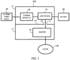
- FIG. 1 is a block diagram illustrating a configuration example of the power conversion apparatus according to Embodiment 1.
- power conversion apparatus 100 is an apparatus to be installed in a vehicle such as an EV and includes: casings 11 and 12; inverter 13, which serves as a power conversion circuit; charging apparatus 14; and junction box 15.
- a single casing is formed by combination of casing 11 (an example of a first casing) and casing 12 (an example of a second casing) and is divided into casings 11 and 12 by partition member 10.
- Partition member 10 is a member serving as the bottom of casing 12 (hereinafter, may be referred to as "bottom member").
- Casings 11 and 12 are molded using an aluminum cast, for example, and are heat-resistant and rigid. Casings 11 and 12 are ensured for airtightness in order to prevent entry of a water droplet or dust or the like into casing 11 and 12, respectively.
- Casing 11 includes inverter 13 in an inner portion (an example of a first space) of casing 11.
- Inverter 13 converts a direct current (or DC-power) supplied from battery 30 to a three-phase alternating-current (or AC power) and outputs the current to motor 40.
- casing 12 includes charging apparatus 14 and junction box 15 in an inner portion (an example of a second space) of casing 12.
- Charging apparatus 14 includes an AC-DC conversion circuit and/or a DC-DC conversion circuit and receives power from external power supply 20 and generates a charging voltage for battery 30.
- Junction box 15 is an apparatus configured to relay electrical connection between battery 30, charging apparatus 14, and inverter 13 and also to distribute the flow of power, and is called an electricity distribution box.
- Charging apparatus 14 is electrically connected to external power supply (commercial power supply) 20 via an external connector (not illustrated) and electrically connected to junction box 15.
- external power supply commercial power supply
- junction box 15 electrically connected to external connector 20 via an external connector (not illustrated) and electrically connected to junction box 15.
- charging apparatus 14 and junction box 15 are connected via a bus bar.
- Junction box 15 is connected to battery 30 via a harness, for example.
- charging apparatus 14 converts power from external power supply 20 into a direct current from an alternating-current, and charges, via junction box 15, battery 30, which is installed in the vehicle.
- Battery 30 is a secondary battery configured to store power for driving motor 40.
- Inverter 13 is electrically connected to motor 40 and is also electrically connected to junction box 15. Inverter 13 and junction box 15 are connected to each other via bus bar 16.
- Bus bar 16 is made of metal (e.g., made of copper) and has the positive pole and negative pole. Bus bar 16 passes through opening 17, which is formed in partition member 10, and connects inverter 13 and junction box 15 together.
- inverter 13 converts a current supplied from battery 30 via junction box 15 to an alternating-current (e.g., three-phase alternating-current) and supplies the current to motor 40, which is mounted in a vehicle.
- Motor 40 drives a wheel of the vehicle using the alternating-current.
- FIG. 2 is an exploded perspective view illustrating a configuration example of the power conversion apparatus according to Embodiment 1.
- power conversion apparatus 100 is separated into casings 11 and 12, and lid 18.
- Casings 11 and 12, and lid 18 are each made of metal.
- Casings 11 and 12 each substantially has an open-top cuboid shape.
- Casing 12 is superimposed on and fastened with casing 11.
- Bottom member 10 of casing 12 serves as a lid portion of casing 11 when superimposed on chasing 11. Meanwhile, the opening of casing 12 is covered by lid 18. Note that, how casings 11 and 12 are fastened together will be described using FIG. 3 , hereinafter.
- external power supply connection portion 19 which is disposed on a side surface of casing 12, serves as an interface for connection with external power supply 20.
- casing 12 includes a battery connection portion (not illustrated), which serves as an interface for connection with battery 30, and which is disposed on a side surface opposite to the side surface where external power supply connection portion 19 is disposed.
- a motor connection portion (not illustrated), which serves as an interface for connection with motor 40 is disposed on the bottom of casing 11.
- casing 12 includes one interlock (not illustrated). This interlock detects that lid 18 has been opened (open state of lid 18). With this detection, the current in power conversion apparatus 100 is controlled to stop. Although it will be described hereinafter, a fastening portion for fastening casings 11 and 12 is disposed within each casing. Accordingly, the user always needs to remove lid 18 of casing 12 in order for the user to touch the inside of casing 11. This configuration eliminates the need for an interlock to detect an opening state of the lid in casing 11. Stated differently, the interlock of casing 12 also serves as the interlock for casing 11.
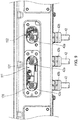
- FIG. 3 is a lateral cross-sectional view illustrating a configuration example of the fastening portion of power conversion apparatus 100 according to Embodiment 1.
- the fastening portion for fastening casings 11 and 12 is disposed inside casings 11 and 12.
- the fastening portion is formed of screw 21 and screw hole 22, for example.
- Screw hole 22 is formed in each of casings 11 and 12.
- casing 11 is appropriately superimposed on casing 12
- Casings 11 and 12 are fastened together by inserting screw 21 into screw hole 22. Note that, although only one position of the fastening portion is illustrated in FIG. 3 , it is preferred that a plurality of fastening portions identical to the fastening portion mentioned above be disposed inside of each casing.
- FIG. 4 is a lateral cross-sectional view illustrating a configuration example for a position around the bus bar of power conversion apparatus 100 according to Embodiment 1. Note that, illustration of the fastening portion (screw 21 and screw hole 22) illustrated in FIG. 3 is omitted in FIG. 4 .
- junction box 15 is formed in a partially protruding shape.
- the partially protruding portion of junction box 15 is referred to as protruding portion 24 and is inserted into opening 17 and serves as a connection portion (insertion port) for bus bar 16.
- Protruding portion 24 includes a portion near the opening which is formed as insulation portion 23. Furthermore, as described above, bus bar 16 passes through opening 17 and connects inverter 13 and junction box 15 together.
- FIGS. 5A and 5B are each a lateral cross-sectional view illustrating an example of an in-vehicle installation position of power conversion apparatus 100 according to Embodiment 1.
- the charging apparatus, junction box, inverter, motor, and battery are denoted by "CHG,” “JB,” “INV,” “M,” and “BAT,” respectively, in FIGS. 5A and 5B .
- FIG. 5A illustrates an example in which power conversion apparatus 100 is installed in a front portion of vehicle 1.
- battery 30 is installed in a bottom portion (e.g., under the passenger seat) of vehicle 1.
- Junction box 15 is installed at a position that allows junction box 15 to be connected to battery 30 with the shortest distance in casing 12. As described above, junction box 15 and battery 30 are connected together via a harness.
- FIG. 5B illustrates an example in which power conversion apparatus 100 is installed in a rear portion of vehicle 1.
- battery 30 is installed in a bottom portion (e.g., under the passenger seat) of vehicle 1.
- Junction box 15 is installed at a position that allows junction box 15 to be connected to battery 30 with the shortest distance in casing 12. As described above, junction box 15 and battery 30 are connected together via a harness.
- Power conversion apparatus 100 according to Embodiment 1 described above can bring about the following effects.
- Power conversion apparatus 100 according to Embodiment 1 is characterized in that inverter 13, charging apparatus 14, and junction box 15 are housed in a single casing, and charging apparatus 14 and junction box 15 are electrically connected to each other while junction box 15 and inverter 13 are electrically connected to each other, and junction box 15 and inverter 13 are connected to each other via bus bar 16. More specifically, in power conversion apparatus 100 according to Embodiment 1, a charging apparatus, a junction box, and an inverter are electrically connected to each other in a single casing, so that the casing itself can serve as a cover for the electrically connected portions between these devices.
- the electrical connection according to Embodiment 1 allows the charging apparatus, the junction box and the inverter to be disposed while being fixed at certain positions within a limited space inside the casing. For this reason, there is no need to use a harness. Accordingly, power conversion apparatus 100 according to Embodiment 1 can ensure safety and achieve complete waterproofing without additional costs.
- power conversion apparatus 100 according to Embodiment 1 is characterized in that power conversion apparatus 100 includes a single casing in which two spaces obtained by dividing the space inside the casing using partition member 10, while inverter 13 and junction box 15 are placed in the two different spaces, respectively, but connected to each other via bus bar 16 passing through opening 17, which is formed in portion member 10. More specifically, in power conversion apparatus 100 according to Embodiment 1, an inverter and a junction box are electrically connected to each other within a single casing, so that the casing itself can serve as a cover for the electrical connection portion of the two devices.
- the electrical connection according to Embodiment 1 requires no use of a harness because the charging apparatus, the junction box and the inverter are fixed at certain positions within the limited space, which is the space inside the casing. Accordingly, power conversion apparatus 100 according to Embodiment 1 can ensure safety and achieve complete waterproofing without additional costs.
- Power conversion apparatus 100 according to Embodiment 1 is characterized in that battery 30 is installed in a rear portion or a bottom portion of vehicle 1 while junction box 15 is installed at a position that makes the distance between junction box 15 and the battery shortest within power conversion apparatus 100.
- power conversion apparatus 100 according to Embodiment 1 can reduce the length of the harness connecting the junction box and the battery together, thus reducing the costs.
- higher safety can be achieved in the arrangement illustrated in FIG. 5B than in the arrangement in FIG. 5A . More specifically, in FIG. 5A , it is possible for the user to touch power conversion apparatus 100 when the hood is open, so that this arrangement is not very safe. Meanwhile, in FIG. 5B , the user cannot touch power conversion apparatus 10 disposed inside the trunk, even when a rear door is open, so that this arrangement is safe.
- protruding portion 24, which is a part of junction box 15, includes insulation portion 23 and is inserted through opening 17 and serves as a connection portion for bus bar 16.
- power conversion apparatus 100 according to Embodiment 1 can avoid an unsafe situation that may occur when the bus bar comes into contact with a metal-made opening because the screw of the fastening portion comes loose, for example.
- power conversion apparatus 100 according to Embodiment 1 is characterized in that a single casing is divided into the first and the second spaces using partition member 10, while casing 11, which forms the first space, and casing 12, which forms the second space, are separable, and that casings 11 and 12 include fastening portions for fastening casings 11 and 12 together in the first and the second spaces, respectively. Stated differently, the fastening portions are included inside the respective casings.
- power conversion apparatus 100 according to Embodiment 1 can be reduced in length of the lateral width of the entire casing by the length (width) of the fastening portions, which would otherwise be added to the lateral width of the entire casing when the fastening portions are formed outside the respective casings.
- power conversion apparatus 100 according to Embodiment 1 is characterized in that casing 12 is superimposed on and fastened to the casing 11 inside casings 11 and 12, while power conversion apparatus 100 according to Embodiment 1 includes, in casing 12, only one interlock to detect an open state of lid 18 of casing 12.
- power conversion apparatus 100 according to Embodiment 1 does not need to include an interlock in casing 11, thereby making it possible to obtain effects including simplification in shape, a cost reduction for the interlock itself, and a reduction in the number of components required for installation of the interlock, for example.
- junction box 15 according Embodiment 1 is characterized by including protruding portion 24 to be inserted into opening 17, while protruding portion 24 includes insulation portion 23 and serves as a connection portion for bus bar 16.
- the junction box according to Embodiment 1 makes it possible to avoid an unsafe situation that may occur when the bus bar comes into contact with the metal-made opening portion because the screw of the fastening portion comes loose, for example.
- Embodiment 1 of the present invention has been given of Embodiment 1 of the present invention, but the description is an example only, and the following modifications are possible, for example.
- junction box 15 is included in casing 12 together with charging apparatus 14, but the present invention is not limited to this example.
- junction box 15 may be included in casing 11 together with inverter 13.
- Embodiment 1 an example is used to describe Embodiment 1, in which an unsafe situation that may occur when bus bar 16 comes into contact with opening 17 is avoided by including insulation portion 23 in protruding portion 24 of junction box 15, but the present invention is not limited to this example.
- junction box 15 itself may be formed using an insulator (e.g., resin), or the portion of partition member 10 where opening 17 is formed may be coated using an insulating member.
- insulator e.g., resin
- the portion of partition member 10 where opening 17 is formed may be coated using an insulating member.
- Embodiment 1 a configuration is used to describe Embodiment 1, in which battery 30 is installed in a bottom portion of vehicle 1, but the present invention is not limited to this configuration.
- battery 30 may be installed in a front portion or rear portion of the vehicle.
- junction box 15 is installed at a position that makes the distance between junction box 15 and battery 30 shortest in casing 12.
- inverter 13, charging apparatus 14, and junction box 15 are housed in power conversion apparatus 100 in Embodiment 1, for example, the present invention is not limited to this configuration, and another device may be installed in power conversion apparatus 100.
- a DC/DC converter may be housed in power conversion apparatus 100.
- Such a DC/DC converter is used to supply power to an auxiliary battery (12V), for example, and reduces a high voltage of battery 30 to 12V and outputs the power.
- Housing the DC/DC converter within power conversion apparatus 100 increases the number of high voltage cables covered by power conversion apparatus 100, thereby making it possible to further enhance the safety.
- Embodiment 1 a description has been given of a configuration in which power conversion apparatus 100 includes a single casing formed by combination of casings 11 and 12 while partition member 10 serves as a bottom member for casing 12, but the present invention is not limited to this configuration.
- a single casing without combination of a plurality of casings may be employed.
- partition member 10 may be a member that simply divides a space. Note that, the number of partition members 10 is not limited to one, and may be two or more.
- HEVs hybrid electric vehicles
- PHEVs plug-in HEVs
- EVs electric vehicles
- These vehicles are provided with a power conversion apparatus configured to convert power between an external power supply, a storage battery, and a motor, in addition to a storage battery for supplying power.
- a power conversion apparatus is provided with a charging circuit that generates a charging voltage for the storage battery from the external power supply or an inverter circuit that converts a direct current of the storage battery to a three-phase alternating-current and outputs the current to the motor, for example.
- the power conversion apparatus includes a power conversion circuit to which a high voltage is applied or in which a high voltage is generated, so that it is a common practice to configure the power conversion circuit to be covered by a casing (see, e.g., Japanese Patent Applications Laid-open No. 2003-009301 and No. 2005-143200 ).
- the casing is ensured for airtightness in order to prevent entry of a water drop or dust, for example.
- a process of assembling a power conversion apparatus of a production unit to a vehicle may include a step of connecting a power output cable (e.g., output cable for supplying a driving current to a motor) to the power conversion apparatus.
- a power output cable e.g., output cable for supplying a driving current to a motor
- a cable through which a large current flows requires sure connection.
- a connection method for such a cable a connection method of inserting a cable into a casing of a power conversion apparatus and directly connecting the cable to a connection portion is employed, normally, instead of a connection method using a connector. Connecting a cable to the connection portion is performed by inserting a screw driver or the like through a work window of the casing.
- connection portion is provided at a plurality of positions, e.g., three connection portions where three-phase alternating-current is outputted.
- the plurality of connection portions are disposed while being spaced apart from each other in general in consideration of securing a predetermined insulation distance or of the influence of a magnetic field. For this reason, the work window for a plurality of connection portions is formed as a window hole that is long in a direction where the connection portions are aligned or a plurality of window holes aligned in a direction identical to that of the plurality of connection portions.
- an interlock mechanism is required, which ensures safety when the work window is opened.
- an interlock mechanism is a mechanism in which an interlock switch turns and blocks supply of power when the lid of the work window is removed.
- the mechanism e.g., protrusion
- the mechanism e.g., protrusion to turn an interlock switch
- the lid with low costs and a high degree of freedom by resin molding.
- a protrusion having an optimum shape can be easily formed in the lid.
- an O-ring having a similar shape needs to be prepared. In this case, there arises a problem in that it is difficult to keep the airtightness by the O-ring as the length of the certain direction becomes long.
- Embodiment 2 it is made possible to ensure airtightness for a work window of a power conversion apparatus and to achieve easiness of the manufacturing of an interlock mechanism.
- Embodiment 2 The basic configuration of power conversion apparatus 100 according to Embodiment 2 is similar to the configuration illustrated in FIG. 1 , so that the description will not be repeated. Hereinafter, a description will be given of differences from Embodiment 1.
- casing 11 includes two work windows 111 and 112 for directly connecting three-phase output cables 42 to inverter 13 as illustrated in FIG. 6 .
- FIG. 7 is an exploded perspective view illustrating a structure of the work windows and lids of the power conversion apparatus according to Embodiment 2.
- FIG. 8 is a perspective view illustrating how the lids are fixed to the work windows.
- FIG. 9 is a front view illustrating the work windows.
- FIG. 10 is a front view illustrating how a first lid is fixed to a work window.
- FIG. 11 is a front view illustrating first and second lids are fixed to the work windows.
- work windows 111 and 112 are through holes passing through casing 11 from outside of casing 11 to inside thereof.
- Work windows 111 and 112 are formed at positions where three connection portions 131 face work windows 111 and 112.
- Three connection portions 131 are regions where connection terminals 42a of three output cables 42 for transmitting a three-phase alternating-current to motor 40 and the output terminals of inverter 13 are fixedly attached together using screws, for example.
- connection portions 131 are disposed while being spaced apart from each other because of the magnetic influence and a need to secure a predetermined insulation distance. Three connection portions 131 are aligned in a row in parallel with a substrate of inverter 13.
- Three output cables 42 are inserted into the inside of casing 11 via three through holes at a lower portion of casing 11, respectively.
- the airtightness for the three through holes is secured by fastening three cable clamps 42b.
- Work window 111 which is one of the two work windows (hereinafter, may be referred to as "first work window 111") has an elongated hole shape that is long in a certain direction. More specifically, work window 111 has a rectangular shape that is long in the direction in which three connection portions 131 are aligned (rectangular with rounded corners). Two connection portions 131 face work window 111.
- the other one of the work windows which is work window 112 (hereinafter, may be referred to as "second work window 112") is a hole having substantially the same vertical and horizontal lengths. More specifically, work window 112 has substantially a circular shape, or an ellipse shape which has a slightly long side in a certain direction than in the other direction.
- One connection portion 131 faces work window 112.
- casing 11 includes a plurality of lids 51 and 52 for closing work windows 111 and 112, respectively.
- First lid 51 is provided for closing first work window 111 and is a metal lid formed by processing a plate. Lid 51 is fastened to casing 11 via bolts or the like with highly rigid gasket 511 interposed therebetween. Note that, as long as the material has rigidity, lid 51 does not have to be metal.
- Second lid 52 is provided for closing second work window 112 and is integrally molded using a resin.
- lid 52 includes projection 522 (equivalent to an operation portion), which pushes interlock switch 135 (see FIG. 12 ), to be described, hereinafter.
- Lid 52 may be formed to have both a metal portion and a resin portion by insert molding or outsert molding.
- Lid 52 is fastened to casing 11 via bolts.
- Elastic O-ring 521 e.g., rubber O-ring
- O-ring 521 is placed between lid 52 and work window 112, thus sealing the gap between lid 52 and work window 112.
- Lid 52 includes superimposed portion 52a, which is superimposed over one of the lids, lid 51 (hereinafter, may be referred to as “first lid 51”) when lid 52, which is the other one of the lids (hereinafter, may be referred to as “second lid 52") is fastened to casing 11.
- Superimposed portion 52a is configured to be superimposed over fastening portion 51a of lid 51 (outside of the casing), e.g., superimposed over the bolts used for fastening lid 51. With this configuration, as illustrated in FIGS. 8 and 11 , while lid 52 is fastened, bolts for first lid 51 are hidden to prevent lid 51 from being unfastened. More specifically, this structure prevents first lid 51 from being opened unless lid 52 is opened.
- Projection 113 is formed near work window 112 corresponding to lid 52 so as to prevent lid 52 from being attached to the wrong side.
- FIG. 12 is a plan view illustrating an interlock mechanism of the power conversion apparatus according to Embodiment 2.
- Power conversion apparatus 100 includes an interlock mechanism for ensuring safety when work windows 111 and 112 are released.
- the interlock mechanism includes: interlock switch 135, which is disposed inside casing 11; and projection 522, which responds to interlock switch 135 and turns the switch.
- Interlock switch 135 is a contact switch that turns when arm 135a is pushed in, for example.
- Inverter 13 includes a blocking circuit that allows input of power to the inverter when arm 135a is pushed in and that blocks input of power to the inverter when arm 135a, which has been pushed in is released.
- projection 522 is formed in lid 52 and protrudes into the inside of casing 11 from work window 112 so as to push arm 135a of interlock switch 135 while lid 52 is fastened.
- Interlock switch 135 may not be a contact switch and may be a proximity sensor switch that turns the state of the switch when projection 522 comes closer to the switch.
- power conversion apparatus 100 As in Embodiment 1, power conversion apparatus 100 according to Embodiment 2 is installed in a vehicle. The installation of power conversion apparatus 100 will be described with reference to FIGS. 5A and 5B , hereinafter.
- Vehicle 1 illustrated in FIG. 5A is an example in which running motor 40 is disposed near a front wheel axle.
- Battery 30 is installed in a bottom portion (e.g., under the passenger seat) of vehicle 1. In this case, it is favorable to install power conversion apparatus 100 at a front position of vehicle 1 that allows power conversion apparatus 100 to be connected to motor 40 with the shortest distance.
- Vehicle 1 in FIG. 5B is an example in which running motor 40 is disposed near a rear wheel axle.
- Battery 30 is installed in a bottom portion (e.g., under the passenger seat) of vehicle 1. In this case, it is favorable to install power conversion apparatus 100 at a rear position of vehicle 1 that allows power conversion apparatus 100 to be connected to motor 40 with the shortest distance.
- the step of connecting output cable 42 to inverter 13 is required after installation of power conversion apparatus 100 of a unit production to vehicle 1 or during the installation.
- connection terminals 42a of three output cables 42 to connection portions 131 of inverter 13. Since lid 52 is removed, interlock switch 135 is turned off, thus blocking input of power to inverter 13. Accordingly, the connection work can be performed while safety is ensured.
- second lid 52 is fastened so as to partially overlap first lid 51. Accordingly, providing the interlock mechanism that interlocks with the opening and closing of second lid 52 alone makes it possible to ensure safety related to opening of work windows 111 and 112. More specifically, first lid 51 cannot be removed unless second lid 52 is removed.
- a plurality of lids 51 and 52 are provided for closing work windows 111 and 112, respectively.
- second lid 52 which requires the operation portion (e.g., protrusion) of the interlock mechanism, can be formed in a small shape (or a shape having substantially the same vertical and lateral dimensions).
- use of a resin-made lid for second lid 52 allows the operation portion (e.g., projection) of the interlock mechanism to be formed easily at low costs and also makes it possible to ensure high airtightness easily with an O-ring.
- first lid 51 which requires no operation portion (e.g., projection) of the interlock mechanism
- work window 111 which corresponds to first lid 51
- first lid 51 which requires no operation portion (e.g., projection) of the interlock mechanism
- work window 111 which corresponds to first lid 51
- Embodiment 2 of the present invention has been described thus far, but the description provided above is only an example. Accordingly, the following modifications are possible, for example.
- the interlock mechanism may be configured to block at least application of a high voltage to connection portions 131.
- the configuration including two work windows 111 and 112, and two lids 51 and 52 has been described as an example, but a configuration including "n" work windows and "n” lids (where “n” is a natural number equal to or greater than three) may be employed.
- the "n” lids are each configured to partially overlap another lid and are configured in such a manner that the lids except the last lid cannot be removed unless another lid is removed.
- the operation portion (e.g., projection) of the interlock mechanism is formed in the lid to be fastened last.
- Embodiment 2 a configuration including two work windows 111 and 112 and two lids 51 and 52 has been described as an example, but a configuration including one work window and two lids may be employed.
- a first lid covers the entire circumference of one work window
- a through hole serving as a small work window may be formed in a part of the first lid
- a second lid is configured to cover the work window formed in the first lid.
- Embodiment 2 the configuration in which second lid 52 partially overlaps fastening portion 51a (bolts) of first lid 51 has been described as an example.
- second lid 52 overlaps a portion of first lid 51 other than the fastening portion of first lid 51, thereby making first lid 51 unremovable unless second lid 52 is removed.
- first and second lids 51 and 52 are configured to be collectively fastened to casing 11 at a portion where first and second lids 51 and 52 overlap each other.
- insertion holes that overlap each other are formed in first and second lids 51 and 52, respectively, and one bolt is inserted through both of the insertion holes to fasten first and second lids 51 and 52 to casing 11.
- work windows 111 and 112 have been described as work windows for connection of output cables 42 of motor 40, a work window for connection of a terminal of a harness for power input, or work windows for various purposes may be provided.
- inverter 13, charging apparatus 14, and junction box 15 have been described as examples of the circuit to be housed in a casing of the power conversion apparatus.
- a circuit to be housed in a casing of the power conversion apparatus only an inverter or a charging apparatus, or various high voltage circuits to which a high voltage is applied or in which a high voltage is generated may be employed.
- the present invention is applicable to a power conversion apparatus to be installed in a vehicle.
Applications Claiming Priority (4)
| Application Number | Priority Date | Filing Date | Title |
|---|---|---|---|
| JP2013078546A JP6160905B2 (ja) | 2013-04-04 | 2013-04-04 | 電気接続構造およびジャンクションボックス |
| JP2013078544A JP6160904B2 (ja) | 2013-04-04 | 2013-04-04 | 電気接続構造 |
| JP2013140526A JP6124008B2 (ja) | 2013-07-04 | 2013-07-04 | 電力変換装置 |
| PCT/JP2014/001859 WO2014162712A1 (ja) | 2013-04-04 | 2014-03-28 | 電力変換装置およびジャンクションボックス |
Publications (3)
| Publication Number | Publication Date |
|---|---|
| EP2983260A1 EP2983260A1 (en) | 2016-02-10 |
| EP2983260A4 EP2983260A4 (en) | 2016-09-07 |
| EP2983260B1 true EP2983260B1 (en) | 2019-12-18 |
Family
ID=51658025
Family Applications (1)
| Application Number | Title | Priority Date | Filing Date |
|---|---|---|---|
| EP14780325.8A Active EP2983260B1 (en) | 2013-04-04 | 2014-03-28 | Power conversion apparatus and junction box |
Country Status (4)
| Country | Link |
|---|---|
| US (2) | US10259329B2 (ja) |
| EP (1) | EP2983260B1 (ja) |
| CN (3) | CN108075419B (ja) |
| WO (1) | WO2014162712A1 (ja) |
Families Citing this family (29)
| Publication number | Priority date | Publication date | Assignee | Title |
|---|---|---|---|---|
| CA2926291C (en) | 2012-10-19 | 2022-04-05 | Chris FORSBERG | Systems and methods for mounting a fuel system |
| DE102015112247A1 (de) * | 2015-07-28 | 2017-02-02 | Dr. Ing. H.C. F. Porsche Aktiengesellschaft | Bordladegerät für ein elektrisch angetriebenes Fahrzeug, Herstellungsverfahren für ein solches und Fahrzeug mit einem solchen Bordladegerät |
| JP6412039B2 (ja) * | 2016-03-17 | 2018-10-24 | 矢崎総業株式会社 | 電力中継器 |
| US10320170B2 (en) | 2016-03-28 | 2019-06-11 | Panasonic Intellectual Property Management Co., Ltd. | Electrical connection structure |
| USD850487S1 (en) * | 2016-08-31 | 2019-06-04 | Sevcon Limited | Electric motor controller |
| US20180069425A1 (en) * | 2016-09-07 | 2018-03-08 | Thunder Power New Energy Vehicle Development Company Limited | Electric vehicle system |
| CN109070754B (zh) * | 2017-03-24 | 2022-07-22 | 法雷奥西门子新能源汽车(深圳)有限公司 | 电气设备及其组装方法 |
| DE102017115632B4 (de) * | 2017-07-12 | 2019-10-24 | Dr. Ing. H.C. F. Porsche Aktiengesellschaft | Leistungselektronisches System für eine Stromtankstelle und entsprechende Stromtankstelle |
| US10828997B2 (en) * | 2017-07-21 | 2020-11-10 | James Richard MOONEY | Electric vehicle onboard recharging system |
| JP7056450B2 (ja) * | 2017-12-06 | 2022-04-19 | 株式会社デンソー | 電気機器とその製造方法 |
| US10660229B2 (en) * | 2017-12-06 | 2020-05-19 | Toyota Jidosha Kabushiki Kaisha | Electrical device and manufacturing method of the same |
| WO2019123871A1 (ja) * | 2017-12-19 | 2019-06-27 | パナソニックIpマネジメント株式会社 | 画像表示装置 |
| JP6819569B2 (ja) * | 2017-12-28 | 2021-01-27 | 株式会社オートネットワーク技術研究所 | 電気接続箱 |
| IT201800002907A1 (it) * | 2018-02-21 | 2019-08-21 | Ferrari Spa | Dispositivo di controllo di interfaccia di potenza di una batteria di propulsione veicolare |
| WO2020008222A1 (ja) * | 2018-07-03 | 2020-01-09 | 日産自動車株式会社 | 電力変換ユニッ卜 |
| IT201800007394A1 (it) * | 2018-07-20 | 2020-01-20 | Caricabatterie per autoveicoli elettrici o ibridi | |
| EP3840972A4 (en) | 2018-08-24 | 2022-05-11 | Hexagon Purus North America Holdings Inc. | BATTERY SYSTEM FOR HEAVY DUTY VEHICLES |
| BR112021020928A2 (pt) | 2019-04-19 | 2022-01-25 | Hexagon Purus North America Holdings Inc | Conjunto de dispositivos acessórios de extremidade dianteira elétrica |
| US10899214B2 (en) | 2019-04-19 | 2021-01-26 | Hexagon Purus North America Holdings Inc. | Electric powertrain system for heavy duty vehicles |
| JP7438481B2 (ja) * | 2019-08-22 | 2024-02-27 | マツダ株式会社 | 車両前部構造 |
| FR3101821A1 (fr) | 2019-10-11 | 2021-04-16 | Psa Automobiles Sa | CONNECTEUR éLECTRIQUE SUR BATTERIE DE TRACTION POUR VÉHICULE ÉLECTRIQUE |
| CA3161967A1 (en) | 2019-11-26 | 2021-06-03 | Hexagon Purus North America Holdings Inc. | Electric vehicle power distribution and drive control modules |
| CN115720421A (zh) * | 2020-03-31 | 2023-02-28 | 华为技术有限公司 | 一种交换机插框及机柜系统 |
| US20210384715A1 (en) * | 2020-06-09 | 2021-12-09 | Michael M. Bogart | Utility junction box |
| CN112104194B (zh) * | 2020-09-09 | 2023-09-05 | 濮阳市立圆汽车电器有限公司 | 一种防脱落自降温式车载逆变器 |
| US11926207B2 (en) | 2020-10-09 | 2024-03-12 | Hexagon Purus North America Holdings Inc. | Battery and auxiliary components for vehicle trailer |
| CA3205080A1 (en) | 2020-12-11 | 2022-06-16 | Hexagon Purus North America Holdings Inc. | Trailer hookup breakaway mitigation systems and methods |
| US11942771B2 (en) * | 2021-01-13 | 2024-03-26 | Sumitomo Wiring Systems, Ltd. | Power distribution box with an engagement feature for overcoming a cantilevered force of a bend in a wire bundle |
| JP2023000567A (ja) * | 2021-06-18 | 2023-01-04 | トヨタ自動車株式会社 | 電力供給ユニットおよび車両 |
Family Cites Families (17)
| Publication number | Priority date | Publication date | Assignee | Title |
|---|---|---|---|---|
| AU703483B2 (en) * | 1997-04-24 | 1999-03-25 | Sumitomo Wiring Systems, Ltd. | Electrical assembly including a connection box having a junction block therein |
| JP3031669B2 (ja) * | 1997-10-13 | 2000-04-10 | 株式会社デンソー | 電力用回路モジュール |
| JP2000253511A (ja) * | 1999-03-04 | 2000-09-14 | Yazaki Corp | Ev用パワーユニットの接続構造 |
| JP2000261936A (ja) * | 1999-03-11 | 2000-09-22 | Yazaki Corp | Ev用電気接続ユニットの組付構造 |
| JP3941423B2 (ja) | 2001-06-15 | 2007-07-04 | トヨタ自動車株式会社 | 車両用パワーコントロールユニット |
| US7030514B2 (en) | 2001-08-17 | 2006-04-18 | Dynagen Technologies Incorporated | Power transfer switch assembly |
| JP2005143200A (ja) | 2003-11-06 | 2005-06-02 | Toyota Motor Corp | 高電圧機器収納箱 |
| US7179990B2 (en) * | 2004-07-31 | 2007-02-20 | Sumitomo Wiring Systems, Ltd. | Electric junction box |
| JP4448111B2 (ja) * | 2006-07-31 | 2010-04-07 | 日立ビークルエナジー株式会社 | 電源システム |
| US7911806B2 (en) * | 2007-09-28 | 2011-03-22 | Hitachi, Ltd | Method and apparatus for reducing EMI emissions from a power inverter |
| JP5166943B2 (ja) | 2008-04-03 | 2013-03-21 | 矢崎総業株式会社 | バスバーの組付構造 |
| US8207454B2 (en) * | 2008-06-27 | 2012-06-26 | Lear Corporation | Electrical junction box |
| WO2010119321A1 (en) * | 2009-04-15 | 2010-10-21 | Nissan Motor Co., Ltd. | Vehicle component mounting arrangement |
| US9030063B2 (en) * | 2010-12-17 | 2015-05-12 | Tesla Motors, Inc. | Thermal management system for use with an integrated motor assembly |
| JP5803259B2 (ja) * | 2011-05-17 | 2015-11-04 | 日産自動車株式会社 | 電気自動車のバッテリパック構造 |
| JP6012143B2 (ja) | 2011-05-17 | 2016-10-25 | 日産自動車株式会社 | 電気自動車の充放電ハーネス配索構造 |
| CN202696030U (zh) * | 2012-07-24 | 2013-01-23 | 常熟开关制造有限公司(原常熟开关厂) | 一种低压配电柜 |
-
2014
- 2014-03-28 CN CN201711474485.8A patent/CN108075419B/zh active Active
- 2014-03-28 US US14/777,594 patent/US10259329B2/en active Active
- 2014-03-28 WO PCT/JP2014/001859 patent/WO2014162712A1/ja active Application Filing
- 2014-03-28 EP EP14780325.8A patent/EP2983260B1/en active Active
- 2014-03-28 CN CN201480015668.1A patent/CN105144520B/zh active Active
- 2014-03-28 CN CN201910034830.9A patent/CN110021902A/zh not_active Withdrawn
-
2018
- 2018-08-31 US US16/118,844 patent/US10661668B2/en active Active
Non-Patent Citations (1)
| Title |
|---|
| None * |
Also Published As
| Publication number | Publication date |
|---|---|
| CN108075419A (zh) | 2018-05-25 |
| EP2983260A1 (en) | 2016-02-10 |
| US20160272073A1 (en) | 2016-09-22 |
| CN108075419B (zh) | 2021-02-19 |
| WO2014162712A1 (ja) | 2014-10-09 |
| US10661668B2 (en) | 2020-05-26 |
| EP2983260A4 (en) | 2016-09-07 |
| CN105144520B (zh) | 2019-02-12 |
| US20180370367A1 (en) | 2018-12-27 |
| US10259329B2 (en) | 2019-04-16 |
| CN110021902A (zh) | 2019-07-16 |
| CN105144520A (zh) | 2015-12-09 |
Similar Documents
| Publication | Publication Date | Title |
|---|---|---|
| US10661668B2 (en) | Power conversion apparatus and junction box | |
| JP6124008B2 (ja) | 電力変換装置 | |
| CN104411972B (zh) | 逆变器一体式电动压缩机 | |
| JP6160905B2 (ja) | 電気接続構造およびジャンクションボックス | |
| JP6241696B2 (ja) | 電気接続構造 | |
| EP2842795B1 (en) | Electric vehicle charging station with reconfigurable electrical installation options and methods | |
| EP2735062B1 (en) | Connector with shield shell for cable | |
| CN107813689B (zh) | 电力设备单元及车辆 | |
| KR102616880B1 (ko) | 버스바 분산 전력감지모듈이 내장된 전기차 전력분배장치 | |
| ITBO20110466A1 (it) | Sistema di connessione per stabilire un collegamento elettrico tra un dispositivo elettrico per autotrazione ed almeno una coppia di cavi | |
| JP6160904B2 (ja) | 電気接続構造 | |
| JP2013138570A (ja) | 高電圧機器 | |
| US10516243B2 (en) | Wire harness connecting structure for two circuit assemblies | |
| JP6452057B2 (ja) | 電気接続構造 | |
| CN215244688U (zh) | 车载集成电子设备及汽车 | |
| JP6068884B2 (ja) | 電池パックの端子部保護カバー | |
| JP6688982B2 (ja) | 電気接続構造 | |
| JP2016004608A (ja) | カバー、配線モジュールおよびカバーの製造方法 | |
| EP4140825B1 (en) | Electrical junction box | |
| WO2019131558A1 (ja) | シールド付き電気ケーブル用端子台装置 | |
| JP2020089004A (ja) | 電力変換装置 | |
| WO2018054453A1 (en) | An electrical junction box | |
| JP2004304922A (ja) | コンバータ | |
| JP2014053102A (ja) | 電池パックの端子部保護カバー | |
| JP2017034943A (ja) | 給電端子、電気接続箱及びワイヤハーネス |
Legal Events
| Date | Code | Title | Description |
|---|---|---|---|
| PUAI | Public reference made under article 153(3) epc to a published international application that has entered the european phase |
Free format text: ORIGINAL CODE: 0009012 |
|
| 17P | Request for examination filed |
Effective date: 20150904 |
|
| AK | Designated contracting states |
Kind code of ref document: A1 Designated state(s): AL AT BE BG CH CY CZ DE DK EE ES FI FR GB GR HR HU IE IS IT LI LT LU LV MC MK MT NL NO PL PT RO RS SE SI SK SM TR |
|
| AX | Request for extension of the european patent |
Extension state: BA ME |
|
| DAX | Request for extension of the european patent (deleted) | ||
| A4 | Supplementary search report drawn up and despatched |
Effective date: 20160809 |
|
| RIC1 | Information provided on ipc code assigned before grant |
Ipc: H02G 3/16 20060101AFI20160803BHEP Ipc: B60R 16/02 20060101ALI20160803BHEP Ipc: B60L 11/18 20060101ALI20160803BHEP |
|
| STAA | Information on the status of an ep patent application or granted ep patent |
Free format text: STATUS: EXAMINATION IS IN PROGRESS |
|
| 17Q | First examination report despatched |
Effective date: 20180911 |
|
| GRAP | Despatch of communication of intention to grant a patent |
Free format text: ORIGINAL CODE: EPIDOSNIGR1 |
|
| STAA | Information on the status of an ep patent application or granted ep patent |
Free format text: STATUS: GRANT OF PATENT IS INTENDED |
|
| RIC1 | Information provided on ipc code assigned before grant |
Ipc: H02G 3/16 20060101AFI20190626BHEP |
|
| INTG | Intention to grant announced |
Effective date: 20190715 |
|
| GRAS | Grant fee paid |
Free format text: ORIGINAL CODE: EPIDOSNIGR3 |
|
| GRAA | (expected) grant |
Free format text: ORIGINAL CODE: 0009210 |
|
| STAA | Information on the status of an ep patent application or granted ep patent |
Free format text: STATUS: THE PATENT HAS BEEN GRANTED |
|
| AK | Designated contracting states |
Kind code of ref document: B1 Designated state(s): AL AT BE BG CH CY CZ DE DK EE ES FI FR GB GR HR HU IE IS IT LI LT LU LV MC MK MT NL NO PL PT RO RS SE SI SK SM TR |
|
| REG | Reference to a national code |
Ref country code: CH Ref legal event code: EP |
|
| REG | Reference to a national code |
Ref country code: IE Ref legal event code: FG4D |
|
| REG | Reference to a national code |
Ref country code: DE Ref legal event code: R096 Ref document number: 602014058628 Country of ref document: DE |
|
| REG | Reference to a national code |
Ref country code: AT Ref legal event code: REF Ref document number: 1215620 Country of ref document: AT Kind code of ref document: T Effective date: 20200115 |
|
| REG | Reference to a national code |
Ref country code: NL Ref legal event code: MP Effective date: 20191218 |
|
| PG25 | Lapsed in a contracting state [announced via postgrant information from national office to epo] |
Ref country code: LV Free format text: LAPSE BECAUSE OF FAILURE TO SUBMIT A TRANSLATION OF THE DESCRIPTION OR TO PAY THE FEE WITHIN THE PRESCRIBED TIME-LIMIT Effective date: 20191218 Ref country code: SE Free format text: LAPSE BECAUSE OF FAILURE TO SUBMIT A TRANSLATION OF THE DESCRIPTION OR TO PAY THE FEE WITHIN THE PRESCRIBED TIME-LIMIT Effective date: 20191218 Ref country code: LT Free format text: LAPSE BECAUSE OF FAILURE TO SUBMIT A TRANSLATION OF THE DESCRIPTION OR TO PAY THE FEE WITHIN THE PRESCRIBED TIME-LIMIT Effective date: 20191218 Ref country code: GR Free format text: LAPSE BECAUSE OF FAILURE TO SUBMIT A TRANSLATION OF THE DESCRIPTION OR TO PAY THE FEE WITHIN THE PRESCRIBED TIME-LIMIT Effective date: 20200319 Ref country code: NO Free format text: LAPSE BECAUSE OF FAILURE TO SUBMIT A TRANSLATION OF THE DESCRIPTION OR TO PAY THE FEE WITHIN THE PRESCRIBED TIME-LIMIT Effective date: 20200318 Ref country code: BG Free format text: LAPSE BECAUSE OF FAILURE TO SUBMIT A TRANSLATION OF THE DESCRIPTION OR TO PAY THE FEE WITHIN THE PRESCRIBED TIME-LIMIT Effective date: 20200318 Ref country code: FI Free format text: LAPSE BECAUSE OF FAILURE TO SUBMIT A TRANSLATION OF THE DESCRIPTION OR TO PAY THE FEE WITHIN THE PRESCRIBED TIME-LIMIT Effective date: 20191218 |
|
| REG | Reference to a national code |
Ref country code: LT Ref legal event code: MG4D |
|
| PG25 | Lapsed in a contracting state [announced via postgrant information from national office to epo] |
Ref country code: HR Free format text: LAPSE BECAUSE OF FAILURE TO SUBMIT A TRANSLATION OF THE DESCRIPTION OR TO PAY THE FEE WITHIN THE PRESCRIBED TIME-LIMIT Effective date: 20191218 Ref country code: RS Free format text: LAPSE BECAUSE OF FAILURE TO SUBMIT A TRANSLATION OF THE DESCRIPTION OR TO PAY THE FEE WITHIN THE PRESCRIBED TIME-LIMIT Effective date: 20191218 |
|
| PG25 | Lapsed in a contracting state [announced via postgrant information from national office to epo] |
Ref country code: AL Free format text: LAPSE BECAUSE OF FAILURE TO SUBMIT A TRANSLATION OF THE DESCRIPTION OR TO PAY THE FEE WITHIN THE PRESCRIBED TIME-LIMIT Effective date: 20191218 |
|
| PG25 | Lapsed in a contracting state [announced via postgrant information from national office to epo] |
Ref country code: CZ Free format text: LAPSE BECAUSE OF FAILURE TO SUBMIT A TRANSLATION OF THE DESCRIPTION OR TO PAY THE FEE WITHIN THE PRESCRIBED TIME-LIMIT Effective date: 20191218 Ref country code: PT Free format text: LAPSE BECAUSE OF FAILURE TO SUBMIT A TRANSLATION OF THE DESCRIPTION OR TO PAY THE FEE WITHIN THE PRESCRIBED TIME-LIMIT Effective date: 20200513 Ref country code: RO Free format text: LAPSE BECAUSE OF FAILURE TO SUBMIT A TRANSLATION OF THE DESCRIPTION OR TO PAY THE FEE WITHIN THE PRESCRIBED TIME-LIMIT Effective date: 20191218 Ref country code: EE Free format text: LAPSE BECAUSE OF FAILURE TO SUBMIT A TRANSLATION OF THE DESCRIPTION OR TO PAY THE FEE WITHIN THE PRESCRIBED TIME-LIMIT Effective date: 20191218 Ref country code: NL Free format text: LAPSE BECAUSE OF FAILURE TO SUBMIT A TRANSLATION OF THE DESCRIPTION OR TO PAY THE FEE WITHIN THE PRESCRIBED TIME-LIMIT Effective date: 20191218 |
|
| PG25 | Lapsed in a contracting state [announced via postgrant information from national office to epo] |
Ref country code: IS Free format text: LAPSE BECAUSE OF FAILURE TO SUBMIT A TRANSLATION OF THE DESCRIPTION OR TO PAY THE FEE WITHIN THE PRESCRIBED TIME-LIMIT Effective date: 20200418 Ref country code: SK Free format text: LAPSE BECAUSE OF FAILURE TO SUBMIT A TRANSLATION OF THE DESCRIPTION OR TO PAY THE FEE WITHIN THE PRESCRIBED TIME-LIMIT Effective date: 20191218 Ref country code: SM Free format text: LAPSE BECAUSE OF FAILURE TO SUBMIT A TRANSLATION OF THE DESCRIPTION OR TO PAY THE FEE WITHIN THE PRESCRIBED TIME-LIMIT Effective date: 20191218 |
|
| REG | Reference to a national code |
Ref country code: DE Ref legal event code: R097 Ref document number: 602014058628 Country of ref document: DE |
|
| REG | Reference to a national code |
Ref country code: AT Ref legal event code: MK05 Ref document number: 1215620 Country of ref document: AT Kind code of ref document: T Effective date: 20191218 |
|
| PLBE | No opposition filed within time limit |
Free format text: ORIGINAL CODE: 0009261 |
|
| STAA | Information on the status of an ep patent application or granted ep patent |
Free format text: STATUS: NO OPPOSITION FILED WITHIN TIME LIMIT |
|
| PG25 | Lapsed in a contracting state [announced via postgrant information from national office to epo] |
Ref country code: MC Free format text: LAPSE BECAUSE OF FAILURE TO SUBMIT A TRANSLATION OF THE DESCRIPTION OR TO PAY THE FEE WITHIN THE PRESCRIBED TIME-LIMIT Effective date: 20191218 Ref country code: ES Free format text: LAPSE BECAUSE OF FAILURE TO SUBMIT A TRANSLATION OF THE DESCRIPTION OR TO PAY THE FEE WITHIN THE PRESCRIBED TIME-LIMIT Effective date: 20191218 Ref country code: DK Free format text: LAPSE BECAUSE OF FAILURE TO SUBMIT A TRANSLATION OF THE DESCRIPTION OR TO PAY THE FEE WITHIN THE PRESCRIBED TIME-LIMIT Effective date: 20191218 |
|
| REG | Reference to a national code |
Ref country code: CH Ref legal event code: PL |
|
| 26N | No opposition filed |
Effective date: 20200921 |
|
| PG25 | Lapsed in a contracting state [announced via postgrant information from national office to epo] |
Ref country code: AT Free format text: LAPSE BECAUSE OF FAILURE TO SUBMIT A TRANSLATION OF THE DESCRIPTION OR TO PAY THE FEE WITHIN THE PRESCRIBED TIME-LIMIT Effective date: 20191218 Ref country code: SI Free format text: LAPSE BECAUSE OF FAILURE TO SUBMIT A TRANSLATION OF THE DESCRIPTION OR TO PAY THE FEE WITHIN THE PRESCRIBED TIME-LIMIT Effective date: 20191218 |
|
| REG | Reference to a national code |
Ref country code: BE Ref legal event code: MM Effective date: 20200331 |
|
| PG25 | Lapsed in a contracting state [announced via postgrant information from national office to epo] |
Ref country code: LU Free format text: LAPSE BECAUSE OF NON-PAYMENT OF DUE FEES Effective date: 20200328 |
|
| PG25 | Lapsed in a contracting state [announced via postgrant information from national office to epo] |
Ref country code: IT Free format text: LAPSE BECAUSE OF FAILURE TO SUBMIT A TRANSLATION OF THE DESCRIPTION OR TO PAY THE FEE WITHIN THE PRESCRIBED TIME-LIMIT Effective date: 20191218 Ref country code: IE Free format text: LAPSE BECAUSE OF NON-PAYMENT OF DUE FEES Effective date: 20200328 Ref country code: LI Free format text: LAPSE BECAUSE OF NON-PAYMENT OF DUE FEES Effective date: 20200331 Ref country code: FR Free format text: LAPSE BECAUSE OF NON-PAYMENT OF DUE FEES Effective date: 20200331 Ref country code: CH Free format text: LAPSE BECAUSE OF NON-PAYMENT OF DUE FEES Effective date: 20200331 |
|
| PG25 | Lapsed in a contracting state [announced via postgrant information from national office to epo] |
Ref country code: PL Free format text: LAPSE BECAUSE OF FAILURE TO SUBMIT A TRANSLATION OF THE DESCRIPTION OR TO PAY THE FEE WITHIN THE PRESCRIBED TIME-LIMIT Effective date: 20191218 Ref country code: BE Free format text: LAPSE BECAUSE OF NON-PAYMENT OF DUE FEES Effective date: 20200331 |
|
| GBPC | Gb: european patent ceased through non-payment of renewal fee |
Effective date: 20200328 |
|
| PG25 | Lapsed in a contracting state [announced via postgrant information from national office to epo] |
Ref country code: GB Free format text: LAPSE BECAUSE OF NON-PAYMENT OF DUE FEES Effective date: 20200328 |
|
| PG25 | Lapsed in a contracting state [announced via postgrant information from national office to epo] |
Ref country code: TR Free format text: LAPSE BECAUSE OF FAILURE TO SUBMIT A TRANSLATION OF THE DESCRIPTION OR TO PAY THE FEE WITHIN THE PRESCRIBED TIME-LIMIT Effective date: 20191218 Ref country code: MT Free format text: LAPSE BECAUSE OF FAILURE TO SUBMIT A TRANSLATION OF THE DESCRIPTION OR TO PAY THE FEE WITHIN THE PRESCRIBED TIME-LIMIT Effective date: 20191218 Ref country code: CY Free format text: LAPSE BECAUSE OF FAILURE TO SUBMIT A TRANSLATION OF THE DESCRIPTION OR TO PAY THE FEE WITHIN THE PRESCRIBED TIME-LIMIT Effective date: 20191218 |
|
| PG25 | Lapsed in a contracting state [announced via postgrant information from national office to epo] |
Ref country code: MK Free format text: LAPSE BECAUSE OF FAILURE TO SUBMIT A TRANSLATION OF THE DESCRIPTION OR TO PAY THE FEE WITHIN THE PRESCRIBED TIME-LIMIT Effective date: 20191218 |
|
| PGFP | Annual fee paid to national office [announced via postgrant information from national office to epo] |
Ref country code: DE Payment date: 20220609 Year of fee payment: 10 |
|
| REG | Reference to a national code |
Ref country code: DE Ref legal event code: R081 Ref document number: 602014058628 Country of ref document: DE Owner name: PANASONIC AUTOMOTIVE SYSTEMS CO., LTD., YOKOHA, JP Free format text: FORMER OWNER: PANASONIC INTELLECTUAL PROPERTY MANAGEMENT CO., LTD., OSAKA-SHI, JP |
|
| PGFP | Annual fee paid to national office [announced via postgrant information from national office to epo] |
Ref country code: DE Payment date: 20240320 Year of fee payment: 11 |