EP2980763B1 - Banknote processing device and cash-out and cash-in mechanism thereof - Google Patents
Banknote processing device and cash-out and cash-in mechanism thereof Download PDFInfo
- Publication number
- EP2980763B1 EP2980763B1 EP13879763.4A EP13879763A EP2980763B1 EP 2980763 B1 EP2980763 B1 EP 2980763B1 EP 13879763 A EP13879763 A EP 13879763A EP 2980763 B1 EP2980763 B1 EP 2980763B1
- Authority
- EP
- European Patent Office
- Prior art keywords
- banknote
- dispensing
- receiving mechanism
- retaining piece
- banknotes
- Prior art date
- Legal status (The legal status is an assumption and is not a legal conclusion. Google has not performed a legal analysis and makes no representation as to the accuracy of the status listed.)
- Not-in-force
Links
- 230000007246 mechanism Effects 0.000 title claims description 132
- 238000003825 pressing Methods 0.000 claims description 59
- 230000000903 blocking effect Effects 0.000 claims description 16
- 238000007599 discharging Methods 0.000 claims description 8
- 238000000151 deposition Methods 0.000 description 11
- 238000003860 storage Methods 0.000 description 11
- 238000004064 recycling Methods 0.000 description 7
- 238000000034 method Methods 0.000 description 6
- 230000008569 process Effects 0.000 description 5
- 230000000694 effects Effects 0.000 description 4
- 230000009471 action Effects 0.000 description 3
- 238000005516 engineering process Methods 0.000 description 2
- 238000009434 installation Methods 0.000 description 2
- 239000002184 metal Substances 0.000 description 2
- 229920003023 plastic Polymers 0.000 description 2
- 239000004033 plastic Substances 0.000 description 2
- 230000005489 elastic deformation Effects 0.000 description 1
- 230000006872 improvement Effects 0.000 description 1
- 238000003754 machining Methods 0.000 description 1
- 229920006267 polyester film Polymers 0.000 description 1
- 230000000717 retained effect Effects 0.000 description 1
- 238000000638 solvent extraction Methods 0.000 description 1
Images


Classifications
-
- G—PHYSICS
- G07—CHECKING-DEVICES
- G07D—HANDLING OF COINS OR VALUABLE PAPERS, e.g. TESTING, SORTING BY DENOMINATIONS, COUNTING, DISPENSING, CHANGING OR DEPOSITING
- G07D11/00—Devices accepting coins; Devices accepting, dispensing, sorting or counting valuable papers
- G07D11/10—Mechanical details
- G07D11/16—Handling of valuable papers
-
- B—PERFORMING OPERATIONS; TRANSPORTING
- B65—CONVEYING; PACKING; STORING; HANDLING THIN OR FILAMENTARY MATERIAL
- B65H—HANDLING THIN OR FILAMENTARY MATERIAL, e.g. SHEETS, WEBS, CABLES
- B65H29/00—Delivering or advancing articles from machines; Advancing articles to or into piles
- B65H29/38—Delivering or advancing articles from machines; Advancing articles to or into piles by movable piling or advancing arms, frames, plates, or like members with which the articles are maintained in face contact
- B65H29/40—Members rotated about an axis perpendicular to direction of article movement, e.g. star-wheels formed by S-shaped members
-
- B—PERFORMING OPERATIONS; TRANSPORTING
- B65—CONVEYING; PACKING; STORING; HANDLING THIN OR FILAMENTARY MATERIAL
- B65H—HANDLING THIN OR FILAMENTARY MATERIAL, e.g. SHEETS, WEBS, CABLES
- B65H31/00—Pile receivers
- B65H31/02—Pile receivers with stationary end support against which pile accumulates
-
- B—PERFORMING OPERATIONS; TRANSPORTING
- B65—CONVEYING; PACKING; STORING; HANDLING THIN OR FILAMENTARY MATERIAL
- B65H—HANDLING THIN OR FILAMENTARY MATERIAL, e.g. SHEETS, WEBS, CABLES
- B65H31/00—Pile receivers
- B65H31/04—Pile receivers with movable end support arranged to recede as pile accumulates
- B65H31/06—Pile receivers with movable end support arranged to recede as pile accumulates the articles being piled on edge
-
- B—PERFORMING OPERATIONS; TRANSPORTING
- B65—CONVEYING; PACKING; STORING; HANDLING THIN OR FILAMENTARY MATERIAL
- B65H—HANDLING THIN OR FILAMENTARY MATERIAL, e.g. SHEETS, WEBS, CABLES
- B65H31/00—Pile receivers
- B65H31/30—Arrangements for removing completed piles
- B65H31/3036—Arrangements for removing completed piles by gripping the pile
- B65H31/3045—Arrangements for removing completed piles by gripping the pile on the outermost articles of the pile for clamping the pile
-
- B—PERFORMING OPERATIONS; TRANSPORTING
- B65—CONVEYING; PACKING; STORING; HANDLING THIN OR FILAMENTARY MATERIAL
- B65H—HANDLING THIN OR FILAMENTARY MATERIAL, e.g. SHEETS, WEBS, CABLES
- B65H83/00—Combinations of piling and depiling operations, e.g. performed simultaneously, of interest apart from the single operation of piling or depiling as such
- B65H83/02—Combinations of piling and depiling operations, e.g. performed simultaneously, of interest apart from the single operation of piling or depiling as such performed on the same pile or stack
-
- G—PHYSICS
- G07—CHECKING-DEVICES
- G07D—HANDLING OF COINS OR VALUABLE PAPERS, e.g. TESTING, SORTING BY DENOMINATIONS, COUNTING, DISPENSING, CHANGING OR DEPOSITING
- G07D11/00—Devices accepting coins; Devices accepting, dispensing, sorting or counting valuable papers
- G07D11/10—Mechanical details
- G07D11/14—Inlet or outlet ports
-
- G—PHYSICS
- G07—CHECKING-DEVICES
- G07D—HANDLING OF COINS OR VALUABLE PAPERS, e.g. TESTING, SORTING BY DENOMINATIONS, COUNTING, DISPENSING, CHANGING OR DEPOSITING
- G07D11/00—Devices accepting coins; Devices accepting, dispensing, sorting or counting valuable papers
- G07D11/40—Device architecture, e.g. modular construction
-
- B—PERFORMING OPERATIONS; TRANSPORTING
- B65—CONVEYING; PACKING; STORING; HANDLING THIN OR FILAMENTARY MATERIAL
- B65H—HANDLING THIN OR FILAMENTARY MATERIAL, e.g. SHEETS, WEBS, CABLES
- B65H2701/00—Handled material; Storage means
- B65H2701/10—Handled articles or webs
- B65H2701/19—Specific article or web
- B65H2701/1912—Banknotes, bills and cheques or the like
Definitions
- the present application relates to the field of banknote processing technique, and particularly to a banknote dispensing/receiving mechanism of a banknote processing device.
- the present application further relates to a banknote processing device having the banknote dispensing/receiving mechanism.
- banknote processing device mainly uses a banknote dispensing/receiving mechanism to receive and dispense banknotes.
- the banknote dispensing/receiving mechanism mainly includes a housing, a baffle, a side plate, a bottom plate, a pressing plate, a banknote pushing plate, a banknote separating mechanism and a banknote-dispensing conveying mechanism.
- the housing is a mounting foundation for the banknote dispensing/receiving mechanism.
- the baffle is arranged on the housing, and is movable upward and downward.
- the pressing plate is configured to support banknotes, and the pressing plate and the banknote pushing plate are both movable with respect to the bottom plate.
- the banknote separating mechanism and the banknote-dispensing conveying mechanism are respectively located at two sides of the bottom plate, and the banknote separating mechanism generally employs a banknote separating wheel.
- the banknote pushing plate is located on the pressing plate at one end close to the banknote-dispensing conveying mechanism.
- the banknote separating mechanism separates the banknotes into single sheets to be conveyed.
- qualified banknotes are delivered into a banknote temporary storage device and unqualified banknotes are delivered to the banknote-dispensing conveying mechanism, and then the unqualified banknotes are conveyed by the banknote-dispensing conveying mechanism into a space formed between the bottom plate and the baffle.
- banknotes in a cash box are delivered along a banknote conveying passage to pass through the banknote identification unit and the banknote-dispensing conveying mechanism and then are stacked in the space formed between the bottom plate and the baffle.
- the pressing plate moves to a vicinity of the baffle, the baffle may move upward or downward to cooperate with the banknote pushing plate to push the banknotes to a banknote dispensing/receiving port.
- a power mechanism including a motor, a belt and a gear or other parts are employed to drive the baffle, which may complicate the structure of the whole banknote dispensing/receiving mechanism.
- the banknote-dispensing conveying mechanism mainly includes the banknote separating wheel, and a complex mechanism is required to drive the banknote separating wheel to operate, which may similarly complicate the structure of the banknote dispensing/receiving mechanism.
- a technical problem to be solved by those skilled in the art is to solve the problem that the banknote dispensing/receiving mechanism of the banknote processing device has a complicated structure.
- CN 102745536A discloses a sheet-like medium stacking apparatus provided for bearing and arranging sheet-like medium.
- the apparatus comprises a bearing plate for receiving and bearing sheet-like medium delivered by the conveyance channel; a blocking mechanism facing an outlet at the end of the conveyance channel and used for preventing the sheet-like medium from continuing to move forward, the blocking mechanism comprising a storage part baffle plate in a lap joint with the bearing plate to form an accommodating chamber accommodating the sheet-like medium; and an arcuate section extending and curving towards the storage part baffle plate, is provided at the end of the bearing plate remote from the conveyance channel, the arcuate section overlapping the storage part baffle plate.
- JP 2000072311A discloses a push-in plate moving those of bills P1 being held in a bill take-in space to a storage space, and two partitioning plates and avoiding any interference between those of bills P2 stored in the storage space bills to be conveyed to the bill take-in space are all installed in a receipts safe stacking the bills upright.
- a push-in auxiliary guide which moved the bills P1 unevenly stacked in the receipts safe to the storage space.
- a banknote dispensing/receiving mechanism of a banknote processing device includes a housing and a baffle, wherein the baffle is an elastic retaining piece, one end of the elastic retaining piece is fixed with respect to the housing and another end of the elastic retaining piece is a free end, and the elastic retaining piece is located in a discharging route of banknotes, wherein the elastic retaining piece includes a first retaining piece and a second retaining piece, a fixed end of the first retaining piece is arranged oppositely to a fixed end of the second retaining piece, and a free end of the first retaining piece and a free end of the second retaining piece are both located in the discharging route of the banknotes, wherein a surface of the first retaining piece facing a banknote pushing plate of the banknote dispensing/receiving mechanism and a surface of the second retaining piece facing the banknote pushing plate are at a same plane, wherein a rectangular corrugated banknote blocking slit is provided between a bottom portion of
- a banknote-dispensing conveying mechanism of the banknote dispensing/receiving mechanism includes a vane wheel, and a banknote pushing plate of the banknote dispensing/receiving mechanism is configured to be located at a side of vanes of the vane wheel to form a banknote blocking mechanism.
- a pressing plate of the banknote dispensing/receiving mechanism is provided with a banknote separating wheel accommodating groove, and a banknote separating wheel of the banknote dispensing/receiving mechanism is configured to pass through the banknote separating wheel accommodating groove, to form a banknote contacting portion exposed out of the banknote separating wheel accommodating groove.
- the housing is provided with a first guide slot, and a pressing plate of the banknote dispensing/receiving mechanism is in a sliding fit with the housing via the first guide slot.
- the housing is provided with a second guide slot, and a banknote pushing plate of the banknote dispensing/receiving mechanism is in a sliding fit with the housing via the second guide slot.
- the banknote dispensing/receiving mechanism of the banknote processing device includes the housing and the baffle, the baffle is the elastic retaining piece, one end of the elastic retaining piece is fixed with respect to the housing, and another end of the elastic retaining piece is a free end, and the elastic retaining piece is located in the discharging route of banknotes.
- the banknote dispensing/receiving mechanism operates, after the banknotes being discharged by the banknote-dispensing conveying mechanism, the banknotes fall onto the elastic retaining piece, and the elastic retaining piece provides a supporting force for the banknotes.
- the banknotes When all the banknotes are discharged, the banknotes are pushed by the banknote pushing plate to apply a pushing force to the elastic retaining piece, and at this moment the elastic retaining piece generates a plastics deformation, which makes the banknotes and the banknote pushing plate pass through the elastic retaining piece together, or makes the banknote pushing plate return to an initial position via the elastic retaining piece, to further perform the subsequent operations.
- the baffle is embodied as the elastic retaining piece, thus compared with the content introduced in the background technology, when the banknotes pass through the baffle, a driving mechanism is not required to drive the baffle to rise and fall, and the banknotes can pass through smoothly by only relying on the elastic deformation of the elastic retaining piece.
- the above banknote dispensing/receiving mechanism omits the driving mechanism for driving the baffle to rise and fall, thus having a simple structure.
- a banknote processing device is further provided by the present application, which includes a banknote dispensing/receiving mechanism, the banknote dispensing/receiving mechanism is any one of the above banknote dispensing/receiving mechanisms. Since the above banknote dispensing/receiving mechanism has the above technical effects, the banknote processing device having the banknote dispensing/receiving mechanism should also have the corresponding technical effects.
- the core of the present application is to provide a banknote dispensing/receiving mechanism of a banknote processing device, and the banknote dispensing/receiving mechanism has a simple structure.
- Another core of the present application is to provide a banknote processing device having the banknote dispensing/receiving mechanism.
- a banknote dispensing/receiving mechanism of a banknote processing device is provided according to an embodiment of the present application, and can be applied in banknote processing devices such as an automatic cash dispenser and an automatic teller machine.
- the structure of the banknote dispensing/receiving mechanism according to the embodiment of the present application is described in detail by taking the banknote dispensing/receiving mechanism used in the automatic teller machine as an example.
- the automatic teller machine includes a display unit 2, a shell 3, a card and detailed statement processing unit 4, an input unit 5, a banknote processing unit 6 and a main body controller 7, and the shell 3 includes a banknote dispensing/receiving port 1.
- the display unit 2 is configured to display an image containing detailed information of various kinds of transactions and options and etc.
- the shell 3 is an installation base for the whole automatic teller machine.
- the card and detailed statement processing unit 4 is mainly used for reading information of cards and issuing detailed statements.
- the input unit 5 is a device for users to input necessary information, and mainly includes a keyboard and etc.
- the banknote processing unit 6 is used to receive banknotes placed into the cash dispensing/receiving port 1 or dispense banknotes via the cash dispensing/receiving port 1 according to the cash withdrawing or depositing operation of the user.
- the main body controller 7 is configured to control the automatic teller machine on the whole, and to accurately control the operation states of each part in the automatic teller machine mainly by processing signals sent from sensors.
- the banknote processing unit 6 mainly includes a banknote dispensing/receiving mechanism 11, a banknote identification unit 12, a banknote conveying passage 13, a banknote temporary storage device 14, a cash container 15, a depositing cash box 16 and a recycling cash box 17, and the depositing cash box 16 and the recycling cash box 17 are both arranged inside the cash container 15.
- a customer first puts banknotes inside the banknote dispensing/receiving mechanism 11, the banknotes inside the banknote dispensing/receiving mechanism 11 are delivered into the banknote identification unit 12 via the banknote conveying passage 13, the banknotes identified to be qualified are delivered into the banknote temporary storage device 14 and the banknotes identified to be unqualified are returned into the banknote dispensing/receiving mechanism 11 and then returned to the customer.
- the qualified banknotes inside the banknote temporary storage device 14 are conveyed through the banknote conveying passage, passes through a conveying port on the cash container 15 and enter into the depositing cash box 16.
- banknotes inside the recycling cash box 17 are conveyed to the banknote identification unit 12, and are then conveyed into the banknote dispensing/receiving mechanism 11, and finally are withdrawn by the customer.
- the depositing cash box 16 and the recycling cash box 17 are interchangeably used, the number of both of the depositing cash box 16 and the recycling cash box 17 can be set flexibly according to specific application occasions.
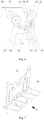
- the banknote dispensing/receiving mechanism mainly includes a housing 25, a side plate 21, a banknote-receiving conveying passage 34, a banknote separating mechanism, a banknote-dispensing conveying passage 26, a banknote-dispensing conveying mechanism, a banknote pushing plate 28, a bottom plate 29 and a pressing plate 32, and the housing 25 is provided with a banknote dispensing/receiving port 22.
- the housing 25 is an installation base of the whole banknote dispensing/receiving mechanism, and the side plate 21, the banknote-receiving conveying passage 34, the banknote separating mechanism, the banknote-dispensing conveying passage 26, the banknote-dispensing conveying mechanism, the banknote pushing plate 28, the bottom plate 29, a baffle and the pressing plate 32 are all arranged on the housing 25.
- the side plate 21 is configured to position the banknote separating mechanism, and meanwhile to limit the position of the banknotes placed into the banknote dispensing/receiving mechanism by the customer.
- the banknote-receiving conveying passage 34 is mainly composed of conveying wheels, and these conveying wheels are driven by a driving device to rotate.
- the banknote separating mechanism is configured to separate a whole stack of banknotes into single sheets of banknotes to facilitate conveying the banknotes, and generally adopts a banknote separating wheel 33.
- the banknote-dispensing conveying passage 26 is configured to convey the banknotes to be withdrawn by the customer or identified to be unqualified by the banknote identification unit to the banknote dispensing/receiving port 22.
- the banknote-dispensing conveying mechanism is arranged adjacent to the banknote-dispensing conveying passage 26, and is configured to convey the banknotes from the banknote-dispensing conveying passage 26 to the bottom plate 29 and then retain the banknotes by the baffle, and the banknote-dispensing conveying mechanism may employ a banknote separating wheel mechanism.
- the banknote pushing plate 28 and the pressing plate 32 can both be driven by the driving device to move with respect to the bottom plate 29, and specifically, the banknote pushing plate 28 and the pressing plate 32 are in a sliding fit with the bottom plate 29.
- a gate at the banknote dispensing/receiving port 22 is opened, the customer places the banknotes in a space enclosed by the side plate 21, the bottom plate 29 and the pressing plate 32, and after all the banknotes are placed in the space, the pressing plate 32 presses the banknotes, a pressure sensor at the position of the banknote separating wheel 33 sends a signal to enable the banknote separating wheel 33 enter into an operating state, the banknote separating wheel 33 separates the banknotes into single sheets, and the single sheets of banknotes are continually conveyed by the banknote-receiving conveying passage 34 into the banknote identification unit.
- the pressing plate 32 moves toward the side plate 21 in the moving direction of the banknote pushing plate 28.
- the banknote separating wheel 33 is arranged on the side plate 21, thus when the pressing plate 32 comes into contact with the banknote separating wheel 33, the pressure sensor at the position of the banknote separating wheel 33 sends a signal to make the banknote pushing plate 28 and the pressing plate 32 both stop moving, and at the same time, the gate at the banknote dispensing/receiving port 22 may be opened to allow the customer to take back the unqualified banknotes.
- banknotes inside the recycling cash box directly enter into the banknote identification unit
- the qualified banknotes may be delivered into the space formed between the baffle and the bottom plate 29 via the banknote-dispensing conveying passage and the banknote-dispensing conveying mechanism, and the remaining process is similar to the banknote depositing process, thus will not be described in detail herein.
- the baffle is an elastic retaining piece
- the elastic retaining piece may be a whole piece having one end fixed with respect to the housing 25 and another end being a free end.
- the free end of the elastic retaining piece can be bent when subjected to an external force, and the elastic retaining piece is located in a discharging route of the banknotes, and the discharging route refers to a distance of banknotes moving to the banknote dispensing/receiving port 22 after being discharged by the banknote-dispensing conveying mechanism.
- the banknotes In the operating process of the banknote dispensing/receiving mechanism, after being discharged by the banknote-dispensing conveying mechanism, the banknotes will fall onto the elastic retaining piece, and the elastic retaining piece provides a supporting force for the banknotes; after the banknotes are all discharged, the banknotes apply a pushing force to the elastic retaining piece under the action of a pushing force of the banknote pushing plate 28, and at this time, the elastic retaining piece may generate a plastic deformation, which makes the banknotes and the banknote pushing plate 28 pass through the elastic retaining piece together and then move toward the side plate 21 with the pressing plate 32, or makes the banknote pushing plate 28 return to the initial position to further perform the subsequent operations.
- the baffle is embodied as the elastic retaining piece, thus compared with the content introduced in the background technology, when the banknotes pass through the baffle, there is no need to employ a driving mechanism to drive the baffle to rise and fall, and the banknotes and the banknote pushing plate can pass through smoothly by just relying on the elasticity of the elastic retaining piece.
- the banknote dispensing/receiving mechanism without the driving mechanism has a simple structure.
- the elastic retaining piece includes a first retaining piece 24 and a second retaining piece 31, and a fixed end of the first retaining piece 24 is arranged oppositely to a fixed end of the second retaining piece 31.
- the first retaining piece 24 may be directly fixed at a top of the housing and the second retaining piece 31 is directly fixed on the bottom plate 29.
- a free end of the first retaining piece 24 and a free end of the second retaining piece 31 are both located in the discharging route of the banknotes, that is, after being discharged by the banknote-dispensing conveying mechanism, the banknotes may be retained by the first retaining piece 24 and the second retaining piece 31.
- the first retaining piece 24 and the second retaining piece 31 are respectively fixed, thus the fixing strength of the whole elastic retaining piece is improved, and the elastic retaining piece can provide a greater supporting force for the banknotes. Meanwhile, the height of each of the first retaining piece 24 and the second retaining piece 31 is lower than the height of the whole piece of the elastic retaining piece, which facilitates the banknotes passing through smoothly.
- the first retaining piece 24 and the second retaining piece 31 may be made from polyester film, the first retaining piece 24 may be adhered to a metal plate, the metal plate is fixed to the housing 25 via a fastener such as screws, and the second retaining piece 31 may be directly adhered to the bottom plate 29.
- the first retaining piece 24 and the second retaining piece 31 may be arranged in staggeredly, that is, the banknotes come into contact with the first retaining piece 24 and the second retaining piece 31 in a certain sequence; considering that in this manner, the first retaining piece 24 and the second retaining piece 31 cannot apply the supporting force to the banknotes at the same time, in the embodiment of the present application, it is preferable that, in the natural state, a surface of the first retaining piece 24 facing the banknote pushing plate 28 and a surface of the second retaining piece 31 facing the banknote pushing plate 28 are at a same plane, and the plane is determined by the movement track of the banknotes, to allow the banknotes to come into contact with the first retaining piece 24 and the second retaining piece 31 simultaneously, thus the first retaining piece 24 and the second retaining piece 31 may provide a reliable supporting force for the banknotes.
- the banknote-dispensing conveying mechanism of the banknote dispensing/receiving mechanism includes a vane wheel 27, multiple vanes on the vane wheel 27 can be used to convey the banknotes, and the banknote pushing plate 28 may be located at a side of the vanes of the vane wheel 27 to form a banknote blocking mechanism.
- the banknotes rotate along with the vanes of the vane wheel 27, and when the banknotes come into contact with the banknote pushing plate 28, the banknote pushing plate 28 stops the banknotes from rotating along with the vanes and makes the banknotes slide along the bottom plate 29 toward the elastic retaining piece.
- the vane wheel 27 does not need a complex driving mechanism, and it is only required to transfer the torsion of a power source directly to a rotation shaft of the vane wheel 27. Obviously, by using the vane wheel, the structure of the whole banknote dispensing/receiving mechanism is simplified.
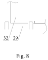
- a curve-shaped banknote blocking slit is provided between a bottom of the pressing plate 32 and the bottom plate 29.
- the bottom surface of the pressing plate 32 and an upper surface of the bottom plate 29 are both embodied as a curved surface, thereby forming the curve-shaped banknote blocking slit between the pressing plate 32 and the bottom plate 29.
- the curve-shaped banknote blocking slit may stop the banknote from passing through the clearance between the pressing plate 32 and the bottom plate 29.
- the clearance between the bottom of the banknote pushing plate 28 and the bottom plate 29 may be set as the curve-shaped banknote blocking clearance.
- the curve-shaped banknote blocking slit may be a wave-shaped banknote blocking slit or a zigzag banknote blocking slit, and etc.
- a rectangular corrugated banknote blocking slit is employed in the embodiment of the present application.
- the bottom of the pressing plate 32 and/or the bottom of the banknote pushing plate 28, and the bottom plate 29 are respectively provided with rectangular protrusions and rectangular grooves for containing the rectangular protrusions.
- a banknote separating wheel accommodating groove is provided on the pressing plate 32, and when the pressing plate 32 is at a tail end of the route, the banknote separating wheel 33 passes through the banknote separating wheel accommodating groove, to form a banknote contacting portion exposed out of the banknote separating wheel accommodating groove.
- the banknote pushing plate 28 the banknotes and the pressing plate 32 move toward the banknote separating wheel 33 together, the banknote separating wheel accommodating groove on the pressing plate 32 gradually passes through the edge of the banknote separating wheel 33, and when the banknotes come into contact with the banknote contacting portion of the banknote separating wheel 33, the pressure sensor sends a signal to make the pressing plate 32 and the banknote pushing plate 28 stop moving.
- the arrangement of the banknote separating wheel accommodating groove makes the banknote pushing plate 28 and the pressing plate 32 stop moving only when the force applied to the banknote separating wheel 33 by the banknotes reaches a predetermined value, obviously, this manner makes the banknotes to be aligned when the banknote pushing plate 28 and the pressing plate 32 apply enough pressure to the banknotes, thus it is easy for the customer to take away the banknotes.
- a first guide slot 23 may be provided on the housing 25, and the pressing plate 32 is in a sliding fit with the housing 25 via the first guide slot 23.
- the pressing plate 32 is in a sliding fit with the first guide slot 23 via a bearing, and a guide block and a guide shaft are arranged on the pressing plate 32. Under the action of a driving device, the pressing plate 32 moves strictly along the track of the first guide slot 23, to prevent situations such as the pressing plate 32 being shaking in the moving process.
- a tail end of the first guide slot 23 may incline upward, to lift the pressing plate 32 upward by a certain distance when the pressing plate 32 moves to a position close to the banknote separating wheel 33, thus a large gap may be formed between the bottom of the pressing plate 32 and the bottom plate 29, to allow the banknotes to move to the banknote-receiving conveying passage under the action of the banknote separating wheel 33.
- the upward inclining and stretching of the tail end of the first guide slot 23 may also facilitate arranging the sensor cooperating with the pressing plate 32.
- a second guide slot 30 may be provided on the housing 25, and the banknote pushing plate 28 of the banknote dispensing/receiving mechanism is in a sliding fit with the housing 25 via the second guide slot 30.
- the banknote pushing plate 28 may similarly in a sliding fit with the second guide slot 30 via a bearing, and a guide block and a guide shaft are provided on the banknote pushing plate 28.
- a banknote processing device is further provided by embodiments of the present application, which includes a banknote dispensing/receiving mechanism, and the banknote dispensing/receiving mechanism is the banknote dispensing/receiving mechanism described in any one of the above technical solutions. Since the banknote dispensing/receiving mechanism has the above technical effects, the banknote processing device having the banknote dispensing/receiving mechanism should also have corresponding technical effects, which will not be described in detail herein.
Applications Claiming Priority (2)
| Application Number | Priority Date | Filing Date | Title |
|---|---|---|---|
| CN201310108591.XA CN103150810B (zh) | 2013-03-29 | 2013-03-29 | 纸币处理设备及其出入钞机构 |
| PCT/CN2013/078971 WO2014153900A1 (zh) | 2013-03-29 | 2013-07-08 | 纸币处理设备及其出入钞机构 |
Publications (3)
| Publication Number | Publication Date |
|---|---|
| EP2980763A1 EP2980763A1 (en) | 2016-02-03 |
| EP2980763A4 EP2980763A4 (en) | 2016-04-06 |
| EP2980763B1 true EP2980763B1 (en) | 2017-09-06 |
Family
ID=48548856
Family Applications (1)
| Application Number | Title | Priority Date | Filing Date |
|---|---|---|---|
| EP13879763.4A Not-in-force EP2980763B1 (en) | 2013-03-29 | 2013-07-08 | Banknote processing device and cash-out and cash-in mechanism thereof |
Country Status (7)
| Country | Link |
|---|---|
| US (1) | US9569910B2 (zh) |
| EP (1) | EP2980763B1 (zh) |
| CN (1) | CN103150810B (zh) |
| AU (1) | AU2013384521B2 (zh) |
| CL (1) | CL2015002368A1 (zh) |
| WO (1) | WO2014153900A1 (zh) |
| ZA (1) | ZA201505902B (zh) |
Families Citing this family (25)
| Publication number | Priority date | Publication date | Assignee | Title |
|---|---|---|---|---|
| CN103150810B (zh) * | 2013-03-29 | 2015-11-25 | 广州广电运通金融电子股份有限公司 | 纸币处理设备及其出入钞机构 |
| JP6072631B2 (ja) * | 2013-07-08 | 2017-02-01 | 日立オムロンターミナルソリューションズ株式会社 | 紙葉類取扱装置 |
| DE102013222077A1 (de) * | 2013-10-30 | 2015-04-30 | Ci Tech Components Ag | Verfahren zur Handhabung von Blattgut |
| CN103559762B (zh) * | 2013-11-05 | 2016-01-20 | 广州广电运通金融电子股份有限公司 | 一种叶轮式纸币暂存机构、纸币处理装置及存取款机 |
| CN103646466B (zh) * | 2013-12-30 | 2016-04-20 | 广州广电运通金融电子股份有限公司 | 风火轮叠钞装置 |
| CN105279843A (zh) * | 2014-05-29 | 2016-01-27 | 恒银金融科技有限公司 | 一种金融自助终端用纸币存取堆叠装置 |
| CN104355191B (zh) * | 2014-09-04 | 2016-12-07 | 广州广电运通金融电子股份有限公司 | 递钞式纸币输送装置 |
| CN105809816B (zh) * | 2014-12-30 | 2018-05-04 | 聚龙股份有限公司 | 一种用于自动柜员机类金融设备的收纳及入钞机构 |
| CN106068529B (zh) * | 2015-01-26 | 2018-12-07 | 株式会社Neo Icp | 媒介处理装置及利用此的媒介处理方法 |
| CN104794804A (zh) * | 2015-04-23 | 2015-07-22 | 新达通科技股份有限公司 | 一种存取款一体机的叠钞机构 |
| CN104821040A (zh) * | 2015-05-28 | 2015-08-05 | 广州广电运通金融电子股份有限公司 | 一种分钞装置 |
| KR20170043190A (ko) * | 2015-10-13 | 2017-04-21 | 노틸러스효성 주식회사 | 매체 처리 장치 및 매체 처리 방법 |
| CN105654612B (zh) * | 2016-01-05 | 2018-08-17 | 新达通科技股份有限公司 | 一种精确控制分钞的atm机分钞装置和系统 |
| CN105809819B (zh) * | 2016-03-10 | 2018-06-15 | 朱昌权 | 带可翻转出钞机构的清分机 |
| CN106023420B (zh) * | 2016-05-18 | 2018-08-17 | 新达通科技股份有限公司 | 一种在存取款一体机的纸币堆叠装置中使用的纸币运输机构 |
| CN106327714A (zh) * | 2016-08-25 | 2017-01-11 | 广州御银科技股份有限公司 | 一种钞票暂存结构 |
| CN106327672A (zh) * | 2016-08-31 | 2017-01-11 | 上海古鳌电子科技股份有限公司 | 一种入钞口的防尘装置 |
| CN106875558B (zh) * | 2017-02-21 | 2019-04-26 | 深圳怡化电脑股份有限公司 | 一种钞票分离装置及其压钞控制方法、自助交易设备 |
| CN107316380A (zh) * | 2017-08-03 | 2017-11-03 | 恒银金融科技股份有限公司 | 存取款机的钞票循环处理装置 |
| CN107958536A (zh) * | 2017-11-20 | 2018-04-24 | 江苏金瑞金融设备有限公司 | 单张拍照出钞机 |
| CN108010187B (zh) * | 2017-12-20 | 2024-04-16 | 浪潮金融信息技术有限公司 | 一种安全推钞机构及其推钞方法 |
| EP3736782A1 (de) * | 2019-05-10 | 2020-11-11 | Wincor Nixdorf International GmbH | Vorrichtung zur handhabung von wertscheinen |
| CN110443942B (zh) * | 2019-09-20 | 2021-10-08 | 深圳怡化电脑股份有限公司 | 一种接客模块及金融自助设备 |
| US11600150B2 (en) * | 2019-10-25 | 2023-03-07 | Hyosung TNS Inc. | Medium stacking sheet and medium separating and stacking apparatus including the same |
| JP2023065964A (ja) * | 2021-10-28 | 2023-05-15 | 日立チャネルソリューションズ株式会社 | 紙幣処理装置及び自動取引装置 |
Family Cites Families (19)
| Publication number | Priority date | Publication date | Assignee | Title |
|---|---|---|---|---|
| JP2900109B2 (ja) * | 1993-05-01 | 1999-06-02 | ローレルバンクマシン株式会社 | 紙幣処理機の紙幣集積装置 |
| DE19736453A1 (de) * | 1997-08-21 | 1999-02-25 | Siemens Nixdorf Inf Syst | Geldein-/ausgabeautomat |
| JP3058150B2 (ja) * | 1998-08-28 | 2000-07-04 | 株式会社日立製作所 | 紙葉類取扱装置 |
| JP3965799B2 (ja) * | 1998-09-17 | 2007-08-29 | 日立オムロンターミナルソリューションズ株式会社 | 紙幣入出金機 |
| US6398000B1 (en) * | 2000-02-11 | 2002-06-04 | Cummins-Allison Corp. | Currency handling system having multiple output receptacles |
| CN1796259A (zh) * | 2004-12-24 | 2006-07-05 | 鈊象电子股份有限公司 | 纸张存放盒 |
| KR101001690B1 (ko) * | 2004-12-30 | 2010-12-28 | 노틸러스효성 주식회사 | 지폐 입출금 장치 |
| JP4713231B2 (ja) * | 2005-06-15 | 2011-06-29 | 日立オムロンターミナルソリューションズ株式会社 | 紙幣処理装置 |
| JP4655777B2 (ja) * | 2005-06-24 | 2011-03-23 | 沖電気工業株式会社 | 紙幣入出金機 |
| CA2617971A1 (en) * | 2005-08-05 | 2007-02-15 | Glory Ltd. | Paper-sheet storing and feeding device |
| KR100802288B1 (ko) * | 2006-12-29 | 2008-02-11 | 노틸러스효성 주식회사 | 지폐입출금장치 |
| JP5340030B2 (ja) * | 2009-05-21 | 2013-11-13 | 日立オムロンターミナルソリューションズ株式会社 | 紙葉類取扱装置 |
| JP5469554B2 (ja) * | 2009-08-28 | 2014-04-16 | ローレル精機株式会社 | シート集積装置 |
| JP5564915B2 (ja) * | 2009-11-30 | 2014-08-06 | 沖電気工業株式会社 | 紙幣入出金機 |
| CN102087765B (zh) * | 2009-12-08 | 2012-10-03 | 广州广电运通金融电子股份有限公司 | 纸币收集装置及自助服务终端 |
| CN101923747B (zh) * | 2010-07-13 | 2012-08-29 | 广州广电运通金融电子股份有限公司 | 自助服务终端及其币式散状介质输送机构和配发装置 |
| WO2012091438A2 (ko) * | 2010-12-31 | 2012-07-05 | 노틸러스효성 주식회사 | 시트롤러를 이용한 지폐집적장치와 지폐집적방법 |
| CN102745536A (zh) * | 2012-06-26 | 2012-10-24 | 广州广电运通金融电子股份有限公司 | 一种薄片类介质堆叠装置 |
| CN103150810B (zh) | 2013-03-29 | 2015-11-25 | 广州广电运通金融电子股份有限公司 | 纸币处理设备及其出入钞机构 |
-
2013
- 2013-03-29 CN CN201310108591.XA patent/CN103150810B/zh active Active
- 2013-07-08 EP EP13879763.4A patent/EP2980763B1/en not_active Not-in-force
- 2013-07-08 WO PCT/CN2013/078971 patent/WO2014153900A1/zh active Application Filing
- 2013-07-08 US US14/767,357 patent/US9569910B2/en not_active Expired - Fee Related
- 2013-07-08 AU AU2013384521A patent/AU2013384521B2/en not_active Ceased
-
2015
- 2015-08-17 ZA ZA2015/05902A patent/ZA201505902B/en unknown
- 2015-08-24 CL CL2015002368A patent/CL2015002368A1/es unknown
Also Published As
| Publication number | Publication date |
|---|---|
| AU2013384521B2 (en) | 2016-12-01 |
| CN103150810B (zh) | 2015-11-25 |
| WO2014153900A1 (zh) | 2014-10-02 |
| EP2980763A4 (en) | 2016-04-06 |
| AU2013384521A1 (en) | 2015-09-10 |
| EP2980763A1 (en) | 2016-02-03 |
| CL2015002368A1 (es) | 2016-01-22 |
| US20150371480A1 (en) | 2015-12-24 |
| CN103150810A (zh) | 2013-06-12 |
| US9569910B2 (en) | 2017-02-14 |
| ZA201505902B (en) | 2020-01-29 |
Similar Documents
| Publication | Publication Date | Title |
|---|---|---|
| EP2980763B1 (en) | Banknote processing device and cash-out and cash-in mechanism thereof | |
| EP2980762B1 (en) | Banknote processing device and circulating cash box mechanism thereof | |
| EP3185222B1 (en) | Rotary paper money conveying device | |
| RU2450359C1 (ru) | Устройство для обработки бумажных листов | |
| JP5267351B2 (ja) | 紙幣入出金機 | |
| US9070241B2 (en) | Bill storage box and bill handling device | |
| JP2007062918A (ja) | 紙葉類堆積装置 | |
| EP2511886A2 (en) | Automatic teller machine | |
| JP2007280299A (ja) | 紙葉類処理装置 | |
| JP2014047073A (ja) | 厚み検出装置及び媒体取引装置 | |
| JP5647798B2 (ja) | 紙葉取扱装置 | |
| JP6064786B2 (ja) | 媒体集積装置及び媒体処理装置 | |
| JP6146229B2 (ja) | 媒体搬送装置及び媒体取引装置 | |
| WO2014061594A1 (ja) | 搬送ユニット付き紙葉類取扱装置 | |
| JP2009217512A (ja) | 紙葉類取扱装置 | |
| JP2002053234A (ja) | 紙葉類送出装置 | |
| JP2010052884A (ja) | 紙葉類取扱装置 | |
| KR100868946B1 (ko) | 종이 매체 반출장치 및 반출방법 | |
| US9384637B2 (en) | Picker for use with an automated banking machine | |
| CN210836309U (zh) | 薄片类介质存储装置及存取款机 | |
| CN210836298U (zh) | 薄片类介质集积装置和薄片类介质处理装置 | |
| JP2906022B2 (ja) | 紙幣自動支払い装置 | |
| JP2019144787A (ja) | 媒体処理装置及び媒体取引装置 | |
| JP2007206911A (ja) | 紙幣取扱装置 | |
| KR100850782B1 (ko) | 금융자동화기기의 출금장치 |
Legal Events
| Date | Code | Title | Description |
|---|---|---|---|
| PUAI | Public reference made under article 153(3) epc to a published international application that has entered the european phase |
Free format text: ORIGINAL CODE: 0009012 |
|
| 17P | Request for examination filed |
Effective date: 20150731 |
|
| AK | Designated contracting states |
Kind code of ref document: A1 Designated state(s): AL AT BE BG CH CY CZ DE DK EE ES FI FR GB GR HR HU IE IS IT LI LT LU LV MC MK MT NL NO PL PT RO RS SE SI SK SM TR |
|
| AX | Request for extension of the european patent |
Extension state: BA ME |
|
| A4 | Supplementary search report drawn up and despatched |
Effective date: 20160307 |
|
| RIC1 | Information provided on ipc code assigned before grant |
Ipc: G07D 11/00 20060101ALI20160301BHEP Ipc: G07D 13/00 20060101AFI20160301BHEP |
|
| DAX | Request for extension of the european patent (deleted) | ||
| GRAP | Despatch of communication of intention to grant a patent |
Free format text: ORIGINAL CODE: EPIDOSNIGR1 |
|
| STAA | Information on the status of an ep patent application or granted ep patent |
Free format text: STATUS: GRANT OF PATENT IS INTENDED |
|
| INTG | Intention to grant announced |
Effective date: 20170208 |
|
| GRAS | Grant fee paid |
Free format text: ORIGINAL CODE: EPIDOSNIGR3 |
|
| GRAA | (expected) grant |
Free format text: ORIGINAL CODE: 0009210 |
|
| STAA | Information on the status of an ep patent application or granted ep patent |
Free format text: STATUS: THE PATENT HAS BEEN GRANTED |
|
| AK | Designated contracting states |
Kind code of ref document: B1 Designated state(s): AL AT BE BG CH CY CZ DE DK EE ES FI FR GB GR HR HU IE IS IT LI LT LU LV MC MK MT NL NO PL PT RO RS SE SI SK SM TR |
|
| REG | Reference to a national code |
Ref country code: GB Ref legal event code: FG4D |
|
| REG | Reference to a national code |
Ref country code: CH Ref legal event code: EP Ref country code: AT Ref legal event code: REF Ref document number: 926630 Country of ref document: AT Kind code of ref document: T Effective date: 20170915 |
|
| REG | Reference to a national code |
Ref country code: IE Ref legal event code: FG4D |
|
| REG | Reference to a national code |
Ref country code: DE Ref legal event code: R096 Ref document number: 602013026433 Country of ref document: DE |
|
| REG | Reference to a national code |
Ref country code: NL Ref legal event code: MP Effective date: 20170906 |
|
| REG | Reference to a national code |
Ref country code: LT Ref legal event code: MG4D |
|
| PG25 | Lapsed in a contracting state [announced via postgrant information from national office to epo] |
Ref country code: HR Free format text: LAPSE BECAUSE OF FAILURE TO SUBMIT A TRANSLATION OF THE DESCRIPTION OR TO PAY THE FEE WITHIN THE PRESCRIBED TIME-LIMIT Effective date: 20170906 Ref country code: SE Free format text: LAPSE BECAUSE OF FAILURE TO SUBMIT A TRANSLATION OF THE DESCRIPTION OR TO PAY THE FEE WITHIN THE PRESCRIBED TIME-LIMIT Effective date: 20170906 Ref country code: FI Free format text: LAPSE BECAUSE OF FAILURE TO SUBMIT A TRANSLATION OF THE DESCRIPTION OR TO PAY THE FEE WITHIN THE PRESCRIBED TIME-LIMIT Effective date: 20170906 Ref country code: NO Free format text: LAPSE BECAUSE OF FAILURE TO SUBMIT A TRANSLATION OF THE DESCRIPTION OR TO PAY THE FEE WITHIN THE PRESCRIBED TIME-LIMIT Effective date: 20171206 Ref country code: LT Free format text: LAPSE BECAUSE OF FAILURE TO SUBMIT A TRANSLATION OF THE DESCRIPTION OR TO PAY THE FEE WITHIN THE PRESCRIBED TIME-LIMIT Effective date: 20170906 |
|
| PG25 | Lapsed in a contracting state [announced via postgrant information from national office to epo] |
Ref country code: ES Free format text: LAPSE BECAUSE OF FAILURE TO SUBMIT A TRANSLATION OF THE DESCRIPTION OR TO PAY THE FEE WITHIN THE PRESCRIBED TIME-LIMIT Effective date: 20170906 Ref country code: LV Free format text: LAPSE BECAUSE OF FAILURE TO SUBMIT A TRANSLATION OF THE DESCRIPTION OR TO PAY THE FEE WITHIN THE PRESCRIBED TIME-LIMIT Effective date: 20170906 Ref country code: GR Free format text: LAPSE BECAUSE OF FAILURE TO SUBMIT A TRANSLATION OF THE DESCRIPTION OR TO PAY THE FEE WITHIN THE PRESCRIBED TIME-LIMIT Effective date: 20171207 Ref country code: BG Free format text: LAPSE BECAUSE OF FAILURE TO SUBMIT A TRANSLATION OF THE DESCRIPTION OR TO PAY THE FEE WITHIN THE PRESCRIBED TIME-LIMIT Effective date: 20171206 Ref country code: RS Free format text: LAPSE BECAUSE OF FAILURE TO SUBMIT A TRANSLATION OF THE DESCRIPTION OR TO PAY THE FEE WITHIN THE PRESCRIBED TIME-LIMIT Effective date: 20170906 |
|
| PG25 | Lapsed in a contracting state [announced via postgrant information from national office to epo] |
Ref country code: NL Free format text: LAPSE BECAUSE OF FAILURE TO SUBMIT A TRANSLATION OF THE DESCRIPTION OR TO PAY THE FEE WITHIN THE PRESCRIBED TIME-LIMIT Effective date: 20170906 |
|
| PG25 | Lapsed in a contracting state [announced via postgrant information from national office to epo] |
Ref country code: RO Free format text: LAPSE BECAUSE OF FAILURE TO SUBMIT A TRANSLATION OF THE DESCRIPTION OR TO PAY THE FEE WITHIN THE PRESCRIBED TIME-LIMIT Effective date: 20170906 Ref country code: CZ Free format text: LAPSE BECAUSE OF FAILURE TO SUBMIT A TRANSLATION OF THE DESCRIPTION OR TO PAY THE FEE WITHIN THE PRESCRIBED TIME-LIMIT Effective date: 20170906 Ref country code: PL Free format text: LAPSE BECAUSE OF FAILURE TO SUBMIT A TRANSLATION OF THE DESCRIPTION OR TO PAY THE FEE WITHIN THE PRESCRIBED TIME-LIMIT Effective date: 20170906 |
|
| PG25 | Lapsed in a contracting state [announced via postgrant information from national office to epo] |
Ref country code: SM Free format text: LAPSE BECAUSE OF FAILURE TO SUBMIT A TRANSLATION OF THE DESCRIPTION OR TO PAY THE FEE WITHIN THE PRESCRIBED TIME-LIMIT Effective date: 20170906 Ref country code: IS Free format text: LAPSE BECAUSE OF FAILURE TO SUBMIT A TRANSLATION OF THE DESCRIPTION OR TO PAY THE FEE WITHIN THE PRESCRIBED TIME-LIMIT Effective date: 20180106 Ref country code: EE Free format text: LAPSE BECAUSE OF FAILURE TO SUBMIT A TRANSLATION OF THE DESCRIPTION OR TO PAY THE FEE WITHIN THE PRESCRIBED TIME-LIMIT Effective date: 20170906 Ref country code: SK Free format text: LAPSE BECAUSE OF FAILURE TO SUBMIT A TRANSLATION OF THE DESCRIPTION OR TO PAY THE FEE WITHIN THE PRESCRIBED TIME-LIMIT Effective date: 20170906 |
|
| REG | Reference to a national code |
Ref country code: DE Ref legal event code: R097 Ref document number: 602013026433 Country of ref document: DE |
|
| PLBE | No opposition filed within time limit |
Free format text: ORIGINAL CODE: 0009261 |
|
| STAA | Information on the status of an ep patent application or granted ep patent |
Free format text: STATUS: NO OPPOSITION FILED WITHIN TIME LIMIT |
|
| REG | Reference to a national code |
Ref country code: FR Ref legal event code: PLFP Year of fee payment: 6 |
|
| PG25 | Lapsed in a contracting state [announced via postgrant information from national office to epo] |
Ref country code: DK Free format text: LAPSE BECAUSE OF FAILURE TO SUBMIT A TRANSLATION OF THE DESCRIPTION OR TO PAY THE FEE WITHIN THE PRESCRIBED TIME-LIMIT Effective date: 20170906 |
|
| 26N | No opposition filed |
Effective date: 20180607 |
|
| PG25 | Lapsed in a contracting state [announced via postgrant information from national office to epo] |
Ref country code: SI Free format text: LAPSE BECAUSE OF FAILURE TO SUBMIT A TRANSLATION OF THE DESCRIPTION OR TO PAY THE FEE WITHIN THE PRESCRIBED TIME-LIMIT Effective date: 20170906 |
|
| REG | Reference to a national code |
Ref country code: CH Ref legal event code: PL |
|
| PG25 | Lapsed in a contracting state [announced via postgrant information from national office to epo] |
Ref country code: MC Free format text: LAPSE BECAUSE OF FAILURE TO SUBMIT A TRANSLATION OF THE DESCRIPTION OR TO PAY THE FEE WITHIN THE PRESCRIBED TIME-LIMIT Effective date: 20170906 Ref country code: LU Free format text: LAPSE BECAUSE OF NON-PAYMENT OF DUE FEES Effective date: 20180708 |
|
| REG | Reference to a national code |
Ref country code: BE Ref legal event code: MM Effective date: 20180731 |
|
| REG | Reference to a national code |
Ref country code: IE Ref legal event code: MM4A |
|
| PG25 | Lapsed in a contracting state [announced via postgrant information from national office to epo] |
Ref country code: IE Free format text: LAPSE BECAUSE OF NON-PAYMENT OF DUE FEES Effective date: 20180708 Ref country code: LI Free format text: LAPSE BECAUSE OF NON-PAYMENT OF DUE FEES Effective date: 20180731 Ref country code: CH Free format text: LAPSE BECAUSE OF NON-PAYMENT OF DUE FEES Effective date: 20180731 |
|
| PG25 | Lapsed in a contracting state [announced via postgrant information from national office to epo] |
Ref country code: BE Free format text: LAPSE BECAUSE OF NON-PAYMENT OF DUE FEES Effective date: 20180731 |
|
| PGFP | Annual fee paid to national office [announced via postgrant information from national office to epo] |
Ref country code: DE Payment date: 20190807 Year of fee payment: 7 Ref country code: FR Payment date: 20190731 Year of fee payment: 7 Ref country code: TR Payment date: 20190702 Year of fee payment: 7 Ref country code: IT Payment date: 20190726 Year of fee payment: 7 |
|
| PGFP | Annual fee paid to national office [announced via postgrant information from national office to epo] |
Ref country code: AT Payment date: 20190725 Year of fee payment: 7 Ref country code: GB Payment date: 20190821 Year of fee payment: 7 |
|
| PG25 | Lapsed in a contracting state [announced via postgrant information from national office to epo] |
Ref country code: MT Free format text: LAPSE BECAUSE OF NON-PAYMENT OF DUE FEES Effective date: 20180708 |
|
| PG25 | Lapsed in a contracting state [announced via postgrant information from national office to epo] |
Ref country code: PT Free format text: LAPSE BECAUSE OF FAILURE TO SUBMIT A TRANSLATION OF THE DESCRIPTION OR TO PAY THE FEE WITHIN THE PRESCRIBED TIME-LIMIT Effective date: 20170906 |
|
| PG25 | Lapsed in a contracting state [announced via postgrant information from national office to epo] |
Ref country code: CY Free format text: LAPSE BECAUSE OF FAILURE TO SUBMIT A TRANSLATION OF THE DESCRIPTION OR TO PAY THE FEE WITHIN THE PRESCRIBED TIME-LIMIT Effective date: 20170906 Ref country code: HU Free format text: LAPSE BECAUSE OF FAILURE TO SUBMIT A TRANSLATION OF THE DESCRIPTION OR TO PAY THE FEE WITHIN THE PRESCRIBED TIME-LIMIT; INVALID AB INITIO Effective date: 20130708 Ref country code: MK Free format text: LAPSE BECAUSE OF NON-PAYMENT OF DUE FEES Effective date: 20170906 |
|
| PG25 | Lapsed in a contracting state [announced via postgrant information from national office to epo] |
Ref country code: AL Free format text: LAPSE BECAUSE OF FAILURE TO SUBMIT A TRANSLATION OF THE DESCRIPTION OR TO PAY THE FEE WITHIN THE PRESCRIBED TIME-LIMIT Effective date: 20170906 |
|
| REG | Reference to a national code |
Ref country code: DE Ref legal event code: R119 Ref document number: 602013026433 Country of ref document: DE |
|
| REG | Reference to a national code |
Ref country code: AT Ref legal event code: MM01 Ref document number: 926630 Country of ref document: AT Kind code of ref document: T Effective date: 20200708 |
|
| GBPC | Gb: european patent ceased through non-payment of renewal fee |
Effective date: 20200708 |
|
| PG25 | Lapsed in a contracting state [announced via postgrant information from national office to epo] |
Ref country code: GB Free format text: LAPSE BECAUSE OF NON-PAYMENT OF DUE FEES Effective date: 20200708 Ref country code: FR Free format text: LAPSE BECAUSE OF NON-PAYMENT OF DUE FEES Effective date: 20200731 |
|
| PG25 | Lapsed in a contracting state [announced via postgrant information from national office to epo] |
Ref country code: AT Free format text: LAPSE BECAUSE OF NON-PAYMENT OF DUE FEES Effective date: 20200708 Ref country code: DE Free format text: LAPSE BECAUSE OF NON-PAYMENT OF DUE FEES Effective date: 20210202 |
|
| REG | Reference to a national code |
Ref country code: AT Ref legal event code: UEP Ref document number: 926630 Country of ref document: AT Kind code of ref document: T Effective date: 20170906 |
|
| PG25 | Lapsed in a contracting state [announced via postgrant information from national office to epo] |
Ref country code: IT Free format text: LAPSE BECAUSE OF NON-PAYMENT OF DUE FEES Effective date: 20200708 |
|
| PG25 | Lapsed in a contracting state [announced via postgrant information from national office to epo] |
Ref country code: TR Free format text: LAPSE BECAUSE OF NON-PAYMENT OF DUE FEES Effective date: 20200708 |