EP2972046B1 - In eine membran integrierte energieaustauschanordnung - Google Patents
In eine membran integrierte energieaustauschanordnung Download PDFInfo
- Publication number
- EP2972046B1 EP2972046B1 EP14765396.8A EP14765396A EP2972046B1 EP 2972046 B1 EP2972046 B1 EP 2972046B1 EP 14765396 A EP14765396 A EP 14765396A EP 2972046 B1 EP2972046 B1 EP 2972046B1
- Authority
- EP
- European Patent Office
- Prior art keywords
- membrane
- outer frame
- energy
- spacer
- panels
- Prior art date
- Legal status (The legal status is an assumption and is not a legal conclusion. Google has not performed a legal analysis and makes no representation as to the accuracy of the status listed.)
- Active
Links
Images


Classifications
-
- F—MECHANICAL ENGINEERING; LIGHTING; HEATING; WEAPONS; BLASTING
- F28—HEAT EXCHANGE IN GENERAL
- F28D—HEAT-EXCHANGE APPARATUS, NOT PROVIDED FOR IN ANOTHER SUBCLASS, IN WHICH THE HEAT-EXCHANGE MEDIA DO NOT COME INTO DIRECT CONTACT
- F28D21/00—Heat-exchange apparatus not covered by any of the groups F28D1/00 - F28D20/00
- F28D21/0015—Heat and mass exchangers, e.g. with permeable walls
-
- F—MECHANICAL ENGINEERING; LIGHTING; HEATING; WEAPONS; BLASTING
- F28—HEAT EXCHANGE IN GENERAL
- F28D—HEAT-EXCHANGE APPARATUS, NOT PROVIDED FOR IN ANOTHER SUBCLASS, IN WHICH THE HEAT-EXCHANGE MEDIA DO NOT COME INTO DIRECT CONTACT
- F28D21/00—Heat-exchange apparatus not covered by any of the groups F28D1/00 - F28D20/00
- F28D21/0001—Recuperative heat exchangers
- F28D21/0003—Recuperative heat exchangers the heat being recuperated from exhaust gases
- F28D21/0005—Recuperative heat exchangers the heat being recuperated from exhaust gases for domestic or space-heating systems
- F28D21/0008—Air heaters
-
- F—MECHANICAL ENGINEERING; LIGHTING; HEATING; WEAPONS; BLASTING
- F28—HEAT EXCHANGE IN GENERAL
- F28D—HEAT-EXCHANGE APPARATUS, NOT PROVIDED FOR IN ANOTHER SUBCLASS, IN WHICH THE HEAT-EXCHANGE MEDIA DO NOT COME INTO DIRECT CONTACT
- F28D21/00—Heat-exchange apparatus not covered by any of the groups F28D1/00 - F28D20/00
- F28D21/0001—Recuperative heat exchangers
- F28D21/0014—Recuperative heat exchangers the heat being recuperated from waste air or from vapors
-
- F—MECHANICAL ENGINEERING; LIGHTING; HEATING; WEAPONS; BLASTING
- F28—HEAT EXCHANGE IN GENERAL
- F28D—HEAT-EXCHANGE APPARATUS, NOT PROVIDED FOR IN ANOTHER SUBCLASS, IN WHICH THE HEAT-EXCHANGE MEDIA DO NOT COME INTO DIRECT CONTACT
- F28D9/00—Heat-exchange apparatus having stationary plate-like or laminated conduit assemblies for both heat-exchange media, the media being in contact with different sides of a conduit wall
- F28D9/0062—Heat-exchange apparatus having stationary plate-like or laminated conduit assemblies for both heat-exchange media, the media being in contact with different sides of a conduit wall the conduits for one heat-exchange medium being formed by spaced plates with inserted elements
-
- F—MECHANICAL ENGINEERING; LIGHTING; HEATING; WEAPONS; BLASTING
- F28—HEAT EXCHANGE IN GENERAL
- F28F—DETAILS OF HEAT-EXCHANGE AND HEAT-TRANSFER APPARATUS, OF GENERAL APPLICATION
- F28F9/00—Casings; Header boxes; Auxiliary supports for elements; Auxiliary members within casings
- F28F9/001—Casings in the form of plate-like arrangements; Frames enclosing a heat exchange core
-
- F—MECHANICAL ENGINEERING; LIGHTING; HEATING; WEAPONS; BLASTING
- F28—HEAT EXCHANGE IN GENERAL
- F28F—DETAILS OF HEAT-EXCHANGE AND HEAT-TRANSFER APPARATUS, OF GENERAL APPLICATION
- F28F2255/00—Heat exchanger elements made of materials having special features or resulting from particular manufacturing processes
- F28F2255/14—Heat exchanger elements made of materials having special features or resulting from particular manufacturing processes molded
- F28F2255/143—Heat exchanger elements made of materials having special features or resulting from particular manufacturing processes molded injection molded
-
- Y—GENERAL TAGGING OF NEW TECHNOLOGICAL DEVELOPMENTS; GENERAL TAGGING OF CROSS-SECTIONAL TECHNOLOGIES SPANNING OVER SEVERAL SECTIONS OF THE IPC; TECHNICAL SUBJECTS COVERED BY FORMER USPC CROSS-REFERENCE ART COLLECTIONS [XRACs] AND DIGESTS
- Y10—TECHNICAL SUBJECTS COVERED BY FORMER USPC
- Y10T—TECHNICAL SUBJECTS COVERED BY FORMER US CLASSIFICATION
- Y10T156/00—Adhesive bonding and miscellaneous chemical manufacture
- Y10T156/10—Methods of surface bonding and/or assembly therefor
Definitions
- Embodiments of the present disclosure generally relate to an energy exchange assembly, and, more particularly, to an energy exchange assembly having one or more membranes that are configured to transfer sensible and/or latent energy therethrough.
- Energy exchange assemblies are used to transfer energy, such as sensible and/or latent energy, between fluid streams.
- air-to-air energy recovery cores are used in heating, ventilation, and air conditioning (HVAC) applications to transfer heat (sensible energy) and moisture (latent energy) between two airstreams.
- HVAC heating, ventilation, and air conditioning
- a typical energy recovery core is configured to precondition outdoor air to a desired condition through the use of air that is exhausted out of the building. For example, outside air is channeled through the assembly in proximity to exhaust air. Energy between the supply and exhaust air streams is transferred therebetween.
- cool and dry outside air is warmed and humidified through energy transfer with the warm and moist exhaust air. As such, the sensible and latent energy of the outside air is increased, while the sensible and latent energy of the exhaust air is decreased.
- the assembly typically reduces post-conditioning of the supply air before it enters the building, thereby reducing overall energy use of the system.
- Energy exchange assemblies such as air-to-air recovery cores may include one or more membranes through which heat and moisture are transferred between air streams. Each membrane may be separated from adjacent membranes using a spacer. Stacked membrane layers separated by spacers form channels that allow air streams to pass through the assembly. For example, outdoor air that is to be conditioned may enter one side of the device, while air used to condition the outdoor air (such as exhaust air or scavenger air) enters another side of the device. Heat and moisture are transferred between the two airstreams through the membrane layers. As such, conditioned supply air may be supplied to an enclosed structure, while exhaust air may be discharged to an outside environment, or returned elsewhere in the building.
- the amount of heat transferred is generally determined by a temperature difference and convective heat transfer coefficient of the two air streams, as well as the material properties of the membrane.
- the amount of moisture transferred in the core is generally governed by a humidity difference and convective mass transfer coefficients of the two air streams, but also depends on the material properties of the membrane.
- While energy recovery assemblies formed through wrapping techniques may reduce cost and minimize membrane waste, the processes of manufacturing such assemblies are typically labor intensive and/or use specialized automated equipment.
- the wrapping may also result in leaks at edges due to faulty seals. For example, gaps typically exist between membrane layers at corners of an energy recovery assembly.
- at least some known wrapping techniques result in a seam being formed that extends along membrane layers. Typically, the seam is sealed using tape, which blocks pore structures of the membranes, and reduces the amount of moisture transfer in the assembly.
- CH193732A discloses an apparatus for bringing liquid media in contact with walls for executing an isobaric thermodynamic phase change.
- GB1354502 discloses heat exchangers for transferring heat between fluids through thin walled members.
- US20090294110 discloses a brazed aluminum counter-flow heat exchanger.
- a membrane panel assembly according to claim 1 an energy exchange assembly according to claim 12, and a method of forming a membrane panel assembly according to claim 15.
- Embodiments of the present disclosure provide energy exchange assemblies having one or more membranes that are directly integrated with an outer frame. Embodiments of the present disclosure may be formed without adhesives or wrapping.
- Certain embodiments of the present disclosure provide a membrane panel configured to be secured within an energy exchange assembly.
- the membrane panel includes an outer frame defining a central opening, and a membrane sheet integrated with the outer frame.
- the membrane sheet spans across the central opening, and is configured to transfer one or both of sensible energy or latent energy therethrough.
- the membrane sheet may be integrated with the outer frame without an adhesive.
- the outer frame may be injection-molded around edge portions of the membrane sheet.
- the membrane sheet may be ultrasonically bonded to the outer frame.
- the membrane sheet may be laser-bonded to the outer frame.
- the membrane sheet may be heat-sealed to the outer frame.
- the outer frame may include a plurality of brackets having inner edges that define the central opening.
- One or more spacer-securing features such as recesses, divots, slots, slits, tabs, or the like, may be formed through or in at least one of the inner edges.
- the outer frame may include a plurality of upstanding corners.
- the outer frame fits together with at least one separate membrane spacer to form at least one airflow channel.
- the outer frame may be integrally molded and formed with at least one membrane spacer.
- an energy exchange assembly may include a plurality of membrane spacers, and a plurality of membrane panels.
- Each of the plurality of membrane panels may include an outer frame defining a central opening defining a fluid channel, and a membrane sheet integrated with the outer frame. The membrane sheet spans across the central opening, and is configured to transfer one or both of sensible energy or latent energy therethrough.
- Each of the plurality of membrane spacers is positioned between two of the plurality of membrane panels.
- the plurality of membrane panels includes a first group of membrane panels and a second group of membrane panels.
- the first group of membrane panels may be orthogonally oriented with respect to the second group of membrane panels.
- each of the plurality of membrane spacers may include a connecting bracket having a reciprocal shape to the plurality of upstanding corners.
- the outer frame may include at least one sloped connecting bracket configured to mate with a reciprocal feature of one of the plurality of spacers.
- the plurality of spacers and the plurality of membrane panels may form stacked layers.
- Certain embodiments of the present disclosure provide a method of forming a membrane panel configured to be secured within an energy exchange assembly.
- the method may include forming an outer frame defining a central opening, and integrating a membrane sheet with the outer frame.
- the membrane sheet spans across the central opening, and is configured to transfer one or both of sensible energy or latent energy therethrough.
- the integrating operation may include injection-molding the outer frame around edge portions of the membrane sheet.
- the integrating operation includes ultrasonically bonding the membrane sheet to the outer frame.
- the integrating operation comprises laser-bonding the membrane sheet to the outer frame.
- the integrating operation includes heat-sealing the membrane sheet to the outer frame.
- the integrating operation may be performed without the use of an adhesive, such as glue, tape, or the like.
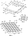
- FIG. 1 illustrates a perspective top view of a membrane panel 100.
- the membrane panel 100 may be used in an energy exchange assembly, such as an energy recovery core, membrane heat exchanger, or the like.
- an energy exchange assembly such as an energy recovery core, membrane heat exchanger, or the like.
- a plurality of membrane panels 100 may be stacked to form an energy exchange assembly.
- the membrane panel 100 includes an outer frame 101 that integrally retains a membrane sheet 102.
- the membrane sheet 102 is integrated with the membrane panel 100.
- the outer frame 101 may have a quadrilateral shape that defines a similarly shaped opening that receives and retains the membrane sheet 102.
- the outer frame 101 may include end brackets 104 that are integrally connected to lateral brackets 106.
- the end brackets 104 may be parallel with one another and perpendicular to the lateral brackets 106.
- the opening may be defined by the end brackets 104 and the lateral brackets 106, which combine to provide four linear frame segments.
- the area of the opening may be slightly less than the area defined by the end brackets 104 and the lateral brackets 106, thereby maximizing an area configured to transfer energy.
- the outer frame 101 may be formed of a plastic or a composite material. Alternatively, the outer frame 101 may be formed of various other shapes and sizes, such as triangular or round shapes.
- each bracket 104 and the lateral brackets 106 may have the same or similar shape, size, and features.
- each bracket 104 or 106 may include a planar main rectangular body 108 having opposed planar upper and lower surfaces 110 and 112, respectively, end edges 114, and opposed outer and inner edges 116 and 118, respectively.
- One or more spacer-securing features 120 such as recesses, divots, slots, slits, or the like, may be formed through or within the inner edge 118.
- the spacer-securing features 120 may be formed through one or both of the upper and lower surfaces 110 and 112.
- the spacer-securing features 120 may provide alignment slots configured to align the membrane panel 100 with a membrane spacer.
- the spacer-securing features 120 may be grooves linearly or irregularly spaced along the inner edges 118 of the brackets 104 and 106, while the membrane spacer includes protuberances, such as tabs, barbs, studs, or the like, that are configured to be received and retained within the spacer-securing features 120.
- the spacer-securing features 120 may be protuberances, while the membrane spacer includes the grooves, for example.
- Figure 2 illustrates a top plan view of the outer frame 101 of the membrane panel 100.
- the membrane sheet 102 (shown in Figure 1 ) is not shown in Figure 2 .
- the outer frame 101 defines an opening 122 into which the membrane sheet 102 is secured. Terminal ends 123 of the end brackets 104 overlay terminal ends 124 of the lateral brackets 106.
- the end brackets 104 may be secured to the lateral brackets 106 through fasteners, adhesives, bonding, and/or the like.
- each bracket 104 and 106 may be separately positioned and secured to form the unitary outer frame 101.
- the outer frame 101 may be integrally molded and formed as shown such as through injection-molding, for example. That is, the outer frame 101 may be a unitary, integrally molded and form piece.
- the end brackets 104 are positioned over the lateral brackets 106 such that an air channel 126 is defined between inner edges 116 of the opposed lateral brackets 106, while an air channel 128 is defined between inner edges 116 of the opposed end brackets 104.
- the air channel 126 is configured to allow an air stream 130 to pass therethrough below the membrane sheet 102 (as shown in Figure 1 ), while the air channel 128 is configured to allow an air stream 132 to pass therethrough above the membrane sheet 102.
- the outer frame 102 may be formed so that the air channels 126 and 128 are perpendicular to one another.
- the air channel 128 may be aligned parallel to an X axis, while the air channel 126 may be aligned parallel with a Y axis, which is orthogonal to the X axis.
- the membrane sheet 102 may be a thin, porous, semi-permeable membrane.
- the membrane sheet 102 may be formed of a microporous material.
- the membrane sheet 102 may be formed of polytetrafluoroethylene (PTFE), polypropylene (PP), nylon, polyvinylidene fluoride (PVDF), polyethersulfone (PES), or the like.
- the membrane sheet 102 may be hydrophilic or hydrophobic.
- the membrane sheet 102 may have the same length and width (for example, the same dimensions in at least one plane) as the outer frame 101.
- the membrane sheet 102 may include a thin, moisture/vapor-promoting polymer film that is coated on a porous polymer substrate.
- the membrane sheet 102 may include a hygroscopic coating that is bonded to a resin or paper-like substrate material.
- the membrane sheet 102 may not be porous.
- the membrane sheet 102 may be formed of a non-porous plastic sheet that is configured to transfer heat, but not moisture, therethrough.
- the membrane sheet 102 may be integrally formed and/or molded with the outer frame 101.
- the membrane sheet 102 may be integrated and/or integrally formed with the frame 101 through a process of injection-molding.
- an injection mold may be sized and shaped to form the membrane panel 100.
- Membrane material may be positioned within the mold and panel material, such as plastic, may be injected into the mold on and/or around portions of the membrane material to form the integral membrane panel 100.
- the membrane material may be injected into the mold, as opposed to a membrane sheet being positioned within the mold.
- the membrane sheet 102 may be integrally formed and molded with the plastic of the outer frame 101.
- the material that forms the outer frame 101 may also form the membrane sheet 102.
- the membrane sheet 102 may be positioned within a mold that is configured to form the membrane panel 100. Hot, liquid plastic is injected into the mold and flows on and/or around portions of the membrane sheet 102. As the plastic cools and hardens to form the outer frame 101, the plastic securely fixes to edge portions of the membrane sheet 102. For example, during the injection molding, the hot, liquid plastic may melt into the membrane sheet 102, thereby securely fastening the outer frame 101 to the membrane sheet 102.
- the membrane panel 100 including the membrane sheet 102 and the outer frame 101, may be formed in a single step, thereby providing an efficient assembly process.
- the membrane sheet 102 may be integrated and/or integrally formed with the outer frame 101 through heat-sealing, ultrasonic bonding or welding, laser-bonding, or the like.
- ultrasonic vibrational energy may be focused into a specific interface area between the membrane sheet 102 and the outer frame 101, thereby securely welding, bonding, or otherwise securely connecting the membrane sheet 102 to the outer frame 101.
- a ridge may extend over and/or around the outer frame 101.
- the membrane sheet 102 may be positioned on the outer frame 101, and the ultrasonic energy may be focused into the interface between the membrane sheet 102 and the ridge.
- laser-bonding may be used to integrate the membrane sheet 102 into the outer frame 101.
- a laser may be used to melt portions of the membrane sheet 102 into portions of the outer frame 101, or vice versa. The heat of the laser melts the membrane sheet 102 and/or the outer frame 101 to one another, thereby providing a secure connection therebetween.
- thermal plate bonding may be used to melt portions of the membrane sheet 102 and the outer frame 101 together.
- the membrane sheet 102 may be integrally secured to lower surfaces 112 of the end brackets 104 and upper surfaces 110 of the lateral brackets 106, or vice versa. Once integrated with the outer frame 102, the membrane sheet 102 spans over and/or through the entire area of the opening 122 (shown in Figure 2 ), and the membrane sheet 102 is sealed to the outer frame 102 along the entire perimeter defined by the lower surfaces 112 of the end brackets 104 and the upper surfaces 110 of the lateral brackets 106. Therefore, the membrane sheet 102 may be integrated or integrally formed with the outer frame 101 without using any adhesives (such as glues, tapes, or the like) or wrapping techniques. Embodiments of the present disclosure provide membrane panels having integrated or integral membrane sheets secured to outer frames without adhesives.
- the membrane panel 100 may include a sealing layer 140, which may be formed of a compressible material, such as foam.
- the sealing layer 140 may be a sealing gasket, for example.
- the sealing layer 140 may be a silicone or an adhesive.
- the sealing layer 140 may include two strips 142 of sealant located along opposing frame segments, such as the end brackets 104.
- FIG 3 illustrates a perspective top view of a membrane or air spacer 200.
- the spacer 200 may be used with the membrane panel 100 shown in Figure 1 .
- the spacer 200 may be formed as a rectangular grid of rails 202 and reinforcing beams 204.
- the rails 202 may each extend along the entire length L of the spacer 200, and the reinforcing beams 204 may fix each rail 202 to the adjacent rails 202.
- the reinforcing beams 204 may be oriented perpendicularly to the rails 202 to form a checkerboard grid pattern.
- the height of the spacer 200 may be the height H of the rails 202.
- the space between the panels 100 may be the height H.
- the rails 202 may be oriented such that the height H of each rail is greater than the width W, as shown in Figure 3 .
- the width W may less than a distance D between adjacent rails 202 in order to maximize air flow through the spacer 200.
- Air through the spacer 200 may be configured to flow through channels 206 located between the rails 202.
- the spacer 200 may include alignment tabs 208 that extend outwardly along the length of the outermost rails 202'.
- the alignment tabs 208 may be configured to be received in the spacer-securing features 120 of the membrane panels 100 (shown in Figures 1 and 2 ) for proper alignment of the membrane panels 100 relative to the spacer 200.
- the alignment tabs 208 may be configured to be received in the spacer-securing features 120, such as slot, divots, or the like, of the membrane panel 100 located above the spacer 200, the membrane panel 100 located below the spacer 200, or both.
- FIG. 4 illustrates a perspective exploded top view of a membrane stack 300.
- the stack 300 may include an air or membrane spacer 200 between two panels 100.
- an energy exchange assembly may be assembled by stacking alternating layers of panels 100 and spacers 200 into the stack 300.
- the spacer 200 may be mounted on top of a lower panel 100a, such that the alignment tabs 208 are received and retained in the spacer-securing features 120 of the panel 100a. Additional sealing between layers may be achieved with the sealing layer 140, which may be injection-molded or attached onto the outer frame 102, for example.
- An upper membrane panel 100b may be subsequently mounted on top of the spacer 200.
- the upper membrane panel 100b may be rotated 90° with respect to the lower panel 100a upon mounting.
- an additional spacer (not shown) may be added above the upper panel 100b and aligns with the upper panel 100b such that a subsequent spacer may be rotated 90° relative to the spacer 200.
- the channels 206 through the spacer 200 may be orthogonal to the channels (not shown) through the adjacent spacer, so that air flows through the channels 206 of the spacer 200 in a cross-flow direction relative to the air through the channels of the adjacent spacer.
- the membrane panels 100 and the spacers 200 may be arranged to support various fluid flow orientations, such as counter-flow, concurrent flow, and the like.
- FIG. 5 illustrates a perspective top view of an energy exchange assembly 400, such as an energy recovery core, membrane heat exchanger, or the like, according to an embodiment of the present disclosure.
- the energy exchange assembly 400 may include a stack of multiple layers 402 of membrane panels 100 and spacers 200. As shown, the energy exchange assembly 400 may be a cross-flow, air-to-air membrane energy recovery core.
- a first fluid stream 403 such as air or other gas(es) enters the energy exchange assembly 400 through channels 206a defined within a first wall 406 of the assembly 400.
- the wall 406 may be defined, at least in part, by the outer edges of the outer frames 102 of the membrane panels 100 in the stack.
- a second fluid stream 404 such as air or other gas(es) enters the assembly 400 through channels 206b defined within a second wall 408 of the assembly 400.
- the first fluid stream 403 direction may be perpendicular to the second fluid stream 404 direction through the assembly 400.
- the spacers 200 may be alternately positioned 90° relative to one another, so that the channels 206b are orthogonal to the channels 206a. Consequently, the fluid stream 403 through the assembly 400 is surrounded above and below by membrane sheets 102 (shown in Figure 1 , for example) that form borders separating the fluid stream 403 from the fluid stream 404, and vice versa.
- membrane sheets 102 shown in Figure 1 , for example
- the energy exchange assembly 400 may be oriented so that the fluid stream 403 may be outside air that is to be conditioned, while the second fluid stream 404 may be exhaust, return, or scavenger air that is used to condition the outside air before the outside air is supplied to downstream HVAC equipment and/or an enclosed space as supply air. Heat and moisture may be transferred between the first and second fluid streams 403 and 404 through the membrane sheets 102 (shown in Figure 1 , for example).
- the membrane panels 100 may be secured between outer upstanding beams 410.
- the beams 410 may generally be at the corners of the energy exchange assembly 400.
- the energy exchange assembly 400 may not include the beams 410. Instead, the energy exchange assembly 400 may be formed through a stack of multiple membrane panels 100.
- the first fluid stream 403 may enter an inlet side 412 as cool, dry air.
- the temperature and humidity of the first fluid stream 403 are both increased through energy transfer with the second fluid stream 404 that enters the energy exchange assembly 400 through an inlet side 414 (that is perpendicular to the inlet side 412) as warm, moist air.
- the first fluid stream 403 passes out of an outlet side 416 as warmer, moister air (as compared to the first fluid stream 403 before passing into the inlet side 412), while the second fluid stream 404 passes out of an outlet side 418 as cooler, drier air (as compared to the second fluid stream 404 before passing into the inlet side 414).
- the temperature and humidity of the first and second fluid streams 403 and 404 passing through the assembly 400 tends to equilibrate with one another.
- warm, moist air within the assembly 400 is cooled and dried by heat exchange with cooler, drier air; while cool, dry air is warmed and moistened by the warmer, cooler air.
- Figure 6 illustrates a perspective top view of an outer casing 502 being positioned on an energy exchange assembly 500, according to an embodiment of the present disclosure.
- Figure 7 illustrates a perspective top view of the energy exchange assembly 500 having the outer casing 502.
- the energy exchange assembly 500 may be as described above with respect to Figure 5 , for example.
- the casing 502 may include a base 504 connected to upstanding corner beams 506, which, in turn, connect to a cover 508.
- the base 504 may be secured to lower ends of the beams 506 through fasteners, for example, while the cover 508 may secure to upper ends of the beams 506 through fasteners, for example.
- the base 504, beams 506, and the cover 508 cooperate to define an internal chamber 510 into which the membrane panels 100 and the spacers 200 may be positioned.
- the outer casing 502 may be formed of a metal (such as aluminum), plastic, or composite material.
- the outer casing 502 is configured to securely maintain the stack 520 in place to prevent misalignment.
- Upper and lower filler members 522 may be aligned vertically above and below the stack 520.
- the upper and lower filler members 522 may be mechanically attached to the cover 508 and the base 504, respectively, to prevent the stack 520 from movement in the vertical plane.
- the outer casing 502 may be riveted, screwed, bolted, or adhered together, for example.
- the filler members 506 may be foam layers (for example, polyurethane, Styrofoam, or the like) that compress the stack 520 under constant pressure.
- Figure 8 illustrates a perspective top view of a stacking frame 600, according to an embodiment of the present disclosure.
- the stacking frame 600 may be used in addition to, or instead of, the outer casing 502 (shown in Figures 6 and 7 ) to arrange multiple membrane stacks 400 in a stacked arrangement.
- FIG. 9 illustrates a perspective top view of an energy exchange assembly 700 having multiple membrane stacks 702 secured within the stacking frame 600, according to an embodiment of the present disclosure.
- the individual membrane stacks 702 may be stacked together in various arrangements to increase the size and to modify/customize the dimensions of the energy exchange assembly 700.
- modular stacks 702 may be used to form an assembly 700 of desired size. Modular membrane panels and/or membrane stacks 702 reduce part costs and the need for additional sizes of injection-molded parts.
- each individual membrane stack 702 may be mounted on the stacking frame 600.
- the stacking frame 600 may be configured to mount eight or fewer membrane stacks 702 arranged in a cube, as shown in Figure 9 .
- the stacking frame 600 may be configured to mount more than eight membrane stacks 702.
- the stacking frame 600 may include multiple frame members 602 that retain the individual membrane stacks 702 within the assembly 700.
- the frame members 602 extend vertically from a base 610, and include corner angle members 607, T-angle members 608, and center cross members 609. While not shown, a top cover may be secured to upper ends of the frame members 602 over the membrane stacks 702.
- the frame members 602 may be configured to keep the membrane stacks 702 separated.
- the center cross member 609 and T-angle members 608 may separate adjacent vertical columns of membrane stacks 702.
- the stacking frame 600 may be formed of extruded aluminum, plastic, or like materials. Sealing between each membrane stack 400 and the frame members 602 may be achieved by lining each member 602 with a thin foam layer, which may compress as the stack is assembled to provide a retention force. Alternatively, or in addition, sealant or silicone may be used.
- Figure 10 illustrates a perspective top view of an outer frame 800 of a membrane panel 802, according to an embodiment of the present disclosure.
- Figure 11 illustrates a corner view of the outer frame 800 of the membrane panel 802.
- a membrane sheet is not shown in Figures 10 and 11 .
- the outer frame 800 may be similar to the outer frame 101, shown in Figures 1 and 2 , for example. However, the outer frame 800 may not have a uniform height throughout. Instead, the outer frame 800 may include corners 804 having a height HI that is greater than a height H2 of the outer frame 800 between the corners 804. The height of the outer frame 800 may smoothly and evenly transition between the height HI and the height H2.
- the difference between the heights H1 and H2 may be formed by a sloping or arcuate segment 806 along the top and/or bottom of the outer frame 800.
- the corners 804 may be sloped or curved to increase height in a radial outward direction from a center 830 of an opening 808, such that the greatest height is at each of the four outer corner edges, with the heights sloping downward towards the opening 808
- Figure 12 illustrates a perspective top view of the membrane panel 802, according to an embodiment of the present disclosure.
- Figure 13 illustrates a perspective top view of a membrane sheet 850 secured to a corner 804 of the outer frame 800 of the membrane panel 802.
- the membrane sheet 850 may be secured to a top surface of the outer frame 800.
- the membrane sheet 850 may be secured to a bottom surface of the outer frame 800.
- a membrane sheet may be secured to the top surface of the outer frame 800, while another membrane sheet may be secured to the bottom surface of the outer frame 800.
- the sloped corners 804 slope the membrane sheet 850 downwardly between the corners 804.
- fluid channels 852 may be defined between the corners 804.
- the membrane sheet 850 may be integrated with the outer frame 800.
- bottom edges of the membrane sheet 850 may be bonded, welded, or the like to the top surface of the outer frame 800.
- an entirety of the the outer frame 800 may be on one side of the membrane sheet 850, rather than on two sides.
- the sloped portions and corners allow for easier bonding, welding, or the like of the membrane sheet 850 to the outer frame 800.
- FIG 14 illustrates a perspective top view of a membrane spacer 900, according to an embodiment of the present disclosure.
- Figure 15 illustrates a lateral view of a stacking connecting bracket 902 of the membrane spacer 900.
- the membrane spacer 900 is similar to the membrane spacer 200 (shown in Figure 3 ), except that that connecting bracket 902 is configured to stack between corners of upper and lower membrane panels 802 (shown in Figure 12 and 13 ).
- the contour of the connecting bracket 902 may be a reciprocal shape to the corners 804 (shown in Figures 12 and 13 ).
- the connecting bracket 902 includes a beveled end 904 having a thin distal tip 906 that connects to an expanded base 908 through a sloped surface 910.
- the thin distal tip 906 is configured to be positioned on top of or below the high distal corners 804, while the expanded base 908 is positioned on or below downwardly sloped portions of the corners 804.
- the membrane spacer 900 is configured to lay flat over the membrane panel 802 shown in Figures 12 and 13 .
- the connecting brackets 902 may include a triangular cross-section (when viewed in cross-section along the profile) on each end to fit against the outer frame 800.
- the connecting brackets 902 may have other than triangular cross-sectional shapes, depending on the size and shape of the outer frame 800.
- a thin foam may be added to one side, through either injection-molding or bonding, or an adhesive or sealant may be used to provide sealing between the connecting brackets 902 and the outer frame 800.
- Additional alignment features may be added to both the outer frame 800 and/or the membrane spacer 900 to ensure proper alignment of each layer within a membrane stack.
- FIG 16 illustrates a perspective exploded top view of a membrane stack 1000, according to an embodiment of the present disclosure.
- the stack 1000 may include alternating layers of the membrane spacers 900 and the membrane panels 802.
- Each membrane panel 802 may include an outer frame 800 having an integrated membrane sheet 852.
- Figure 17 illustrates a perspective top view of an outer frame 1100 of a membrane panel 1102, according to an embodiment of the present disclosure.
- Figure 18 illustrates a perspective top view of a corner 1104 of the outer frame 1100 of the membrane panel 1102.
- the outer frame 1100 is similar to the outer frame 800 shown in Figures 10 and 11 , for example.
- the outer frame 1100 includes two opposed planar brackets 1106 that are parallel with the X axis, and two opposed sloped brackets 1108 that are parallel with the Y axis.
- the brackets 1106 may be secured to the brackets 1108 through fasteners, bonding, welding, or the like.
- the outer frame 110 may be integrally molded and formed as a single piece, such as through injection-molding.
- Figure 19 illustrates a lateral view of a stacking connecting bracket 1200 of a membrane spacer 1202, according to an embodiment of the present disclosure.
- the membrane spacer 1202 is similar to the membrane spacer 900 shown in Figures 14 and 15 , except that that the connecting bracket 1200 is configured to overlay or otherwise connect to the sloped bracket 1108, shown in Figures 17 and 18 .
- the cross-sectional profile of the connecting bracket 1200 may have one side 1204 that is coplanar with a top surface of a beam 1206, and an opposite side 1208 that is sloped in a reciprocal fashion with respect to the slope of the sloped bracket 1108.
- the profile of the connecting bracket 1200 may be a right triangle.
- the profile may be formed having various other shapes and sizes, depending on the size and shape of the outer frame to which the connecting bracket 1200 secures.
- outer frames and the membrane spacers described above may be formed as individual pieces, or integrally formed together as a single piece (such as through injection molding).
- FIG 20 illustrates a simplified schematic view of an energy exchange system 1300 operatively connected to an enclosed structure 1302, according to an embodiment of the present disclosure.
- the energy exchange system 1300 may include a housing 1304, such as a self-contained module or unit that may be mobile (for example, the housing 1304 may be moved among a plurality of enclosed structures), operatively connected to the enclosed structure 1302, such as through a connection line 1306, such as a duct, tube, pipe, conduit, plenum, or the like.
- the housing 1304 may be configured to be removably connected to the enclosed structure 1302.
- the housing 1304 may be permanently secured to the enclosed structure 1302.
- the housing 1304 may be mounted to a roof, outer wall, or the like, of the enclosed structure 1302.
- the enclosed structure 1302 may be a room of a building, a storage structure (such as a grain silo), or the like.
- the housing 1304 includes a supply air inlet 1308 that connects to a supply air flow path 1310.
- the supply air flow path 1310 may be formed by ducts, conduits, plenum, channels, tubes, or the like, which may be formed by metal and/or plastic walls.
- the supply air flow path 1310 is configured to deliver supply air 1312 to the enclosed structure 1302 through a supply air outlet 1314 that connects to the connection line 1306.
- the housing 1304 also includes a regeneration air inlet 1316 that connects to a regeneration air flow path 1318.
- the regeneration air flow path 1318 may be formed by ducts, conduits, plenum, tubes, or the like, which may be formed by metal and/or plastic walls.
- the regeneration air flow path 1318 is configured to channel regeneration air 1320 received from the atmosphere (for example, outside air) back to the atmosphere through an exhaust air outlet 3122.
- the supply air inlet 1308 and the regeneration air inlet 1316 may be longitudinally aligned.
- the supply air inlet 1308 and the regeneration air inlet 1316 may be at opposite ends of a linear column or row of ductwork.
- a separating wall 1324 may separate the supply air flow path 1310 from the regeneration air flow path 1318 within the column or row.
- the supply air outlet 1314 and the exhaust air outlet 1322 may be longitudinally aligned.
- the supply air outlet 1314 and the exhaust air outlet 1322 may be at opposite ends of a linear column or row of ductwork.
- a separating wall 1326 may separate the supply air flow path 1310 from the regeneration air flow path 1318 within the column or row.
- the supply air inlet 1308 may be positioned above the exhaust air outlet 1322, and the supply air flow path 1310 may be separated from the regeneration air flow path 1318 by a partition 1328.
- the regeneration air inlet 1316 may be positioned above the supply air outlet 1314, and the supply air flow path 1310 may be separated from the regeneration air flow path 1318 by a partition 1330.
- the supply air flow path 1310 and the regeneration air flow path 1318 may cross one another proximate to a center of the housing 1304. While the supply air inlet 1308 may be at the top and left of the housing 1304 (as shown in Figure 20 ), the supply air outlet 1314 may be at the bottom and right of the housing 1304 (as shown in Figure 20 ). Further, while the regeneration air inlet 1316 may be at the top and right of the housing 1304 (as shown in Figure 20 ), the exhaust air outlet 1322 may be at the bottom and left of the housing 1304 (as shown in Figure 20 ).
- the supply air flow path 1310 and the regeneration air flow path 1318 may be inverted and/or otherwise re-positioned.
- the exhaust air outlet 1322 may be positioned above the supply air inlet 1308.
- the supply air flow path 1310 and the regeneration air flow path 1318 may be separated from one another by more than the separating walls 1324 and 1326 and the partitions 1328 and 1330 within the housing 1304.
- spaces which may contain insulation, may also be positioned between segments of the supply air flow path 1310 and the regeneration air flow path 1318.
- the supply air flow path 1310 and the regeneration air flow path 3118 may simply be straight, linear segments that do not cross one another.
- the housing 1304 may be shifted 180 degrees about a longitudinal axis aligned with the partitions 1328 and 1330, such that that supply air flow path 1310 and the regeneration air flow path 1318 are side-by-side, instead of one on top of another.
- An air filter 1332 may be disposed within the supply air flow path 1310 proximate to the supply air inlet 1308.
- the air filter 1332 may be a standard HVAC filter configured to filter contaminants from the supply air 1312.
- the energy exchange system 1300 may not include the air filter 1332.
- An energy transfer device 1334 may be positioned within the supply air flow path 1310 downstream from the supply air inlet 1308.
- the energy transfer device 1334 may span between the supply air flow path 1310 and the regeneration air flow path 1318.
- a supply portion or side 1335 of the energy transfer device 1334 may be within the supply air flow path 1310, while a regenerating portion or side 1337 of the energy transfer device 1334 may be within the regeneration air flow path 1318.
- the energy transfer device 1334 may be a desiccant wheel, for example.
- the energy transfer device 1334 may be various other systems and assemblies, such as including liquid-to-air membrane energy exchangers (LAMEEs), as described below.
- LAMEEs liquid-to-air membrane energy exchangers
- An energy exchange assembly 1336 is disposed within the supply air flow path 1310 downstream from the energy transfer device 1334.
- the energy exchange assembly 1336 may be positioned at the junction of the separating walls 1324, 1326 and the partitions 1328, 1330.
- the energy exchange assembly 1336 may be positioned within both the supply air flow path 1310 and the regeneration air flow path 1318. As such, the energy exchange assembly 1336 is configured to transfer energy between the supply air 1312 and the regeneration air 1320.
- One or more fans 1338 may be positioned within the supply air flow path 1310 downstream from the energy exchange assembly 1336.
- the fan(s) 1338 is configured to move the supply air 1312 from the supply air inlet 1308 and out through the supply air outlet 1314 (and ultimately into the enclosed structure 1302).
- the fan(s) 1338 may be located at various other areas of the supply air flow path 1310, such as proximate to the supply air inlet 1308.
- the energy exchange system 1300 may not include the fan(s).
- the energy exchange system 1300 may also include a bypass duct 1340 having an inlet end 1342 upstream from the energy transfer device 1334 within the supply air flow path 1310.
- the inlet end 1342 connects to an outlet end 1344 that is downstream from the energy transfer device 1334 within the supply air flow path 1310.
- An inlet damper 1346 may be positioned at the inlet end 1342, while an outlet damper 1348 may be positioned at the outlet end 1344.
- the dampers 1346 and 1348 may be actuated between open and closed positions to provide a bypass line for the supply air 1312 to bypass around the energy transfer device 1334.
- a damper 1350 may be disposed within the supply air flow path 1310 downstream from the inlet end 1342 and upstream from the energy transfer device 1334.
- the damper 1350 may be closed in order to allow the supply air 1312 to flow into the bypass duct 1340 around the energy transfer device 1334.
- the dampers 1346, 1348, and 1350 may be modulated between fully-open and fully-closed positions to allow a portion of the supply air 1312 to pass through the energy transfer device 1334 and a remaining portion of the supply air 1312 to bypass the energy transfer device 1334.
- the bypass dampers 1346, 1348, and 1350 may be operated to control the temperature and humidity of the supply air 1312 as it is delivered to the enclosed structure 1302. Examples of bypass ducts and dampers are further described in United States Patent Application No. 13/426,793 , which was filed March 22, 2012, and is hereby incorporated by reference in its entirety.
- the energy exchange system 1300 may not include the bypass duct 1340 and dampers 1346, 1348, and 1350.
- the supply air 1312 enters the supply air flow path 1310 through the supply air inlet 1308.
- the supply air 1312 is then channeled through the energy transfer device 1334, which pre-conditions the supply air 1312.
- the supply air 1312 is pre-conditioned and passes through the energy exchange assembly 1336, which conditions the pre-conditioned supply air 1312.
- the fan(s) 1338 may then move the supply air 1312, which has been conditioned by the energy exchange assembly 1336, through the energy exchange assembly 1336 and into the enclosed structure 1302 through the supply air outlet 1314.
- an air filter 1352 may be disposed within the regeneration air flow path 1318 proximate to the regeneration air inlet 1316.
- the air filter 1352 may be a standard HVAC filter configured to filter contaminants from the regeneration air 1320.
- the energy exchange system 1300 may not include the air filter 1352.
- the energy exchange assembly 1336 may be disposed within the regeneration air flow path 1318 downstream from the air filter 1352.
- the energy exchange assembly 1336 may be positioned within both the supply air flow path 1310 and the regeneration air flow path 1318. As such, the energy exchange assembly 1336 is configured to transfer sensible energy and latent energy between the regeneration air 1320 and the supply air 1312.
- a heater 1354 may be disposed within the regeneration air flow path 1318 downstream from the energy exchange assembly 1336.
- the heater 1354 may be a natural gas, propane, or electric heater that is configured to heat the regeneration air 1320 before it encounters the energy transfer device 1334.
- the energy exchange system 1300 may not include the heater 1354.
- the energy transfer device 1334 is positioned within the regeneration air flow path 1318 downstream from the heater 1354. As noted, the energy transfer device 1334 may span between the regeneration air flow path 1318 and the supply air flow path 1310.
- the supply side 1335 of the energy transfer device 1334 is disposed within the supply air flow path 1310 proximate to the supply air inlet 1308, while the regeneration side 1337 of the energy transfer device 1334 is disposed within the regeneration air flow path 1310 proximate to the exhaust air outlet 1322. Accordingly, the supply air 3112 encounters the supply side 1335 as the supply air 1312 enters the supply air flow path 1310 from the outside, while the regeneration air 1320 encounters the regeneration side 1337 just before the regeneration air 1320 is exhausted out of the regeneration air flow path 1318 through the exhaust air outlet 1322.
- One or more fans 1356 may be positioned within the regeneration air flow path 1318 downstream from the energy transfer device 1334.
- the fan(s) 1356 is configured to move the regeneration air 1320 from the regeneration air inlet 1316 and out through the exhaust air outlet 1322 (and ultimately into the atmosphere).
- the fan(s) 1356 may be located at various other areas of the regeneration air flow path 1318, such as proximate to the regeneration air inlet 1316.
- the energy exchange system 1300 may not include the fan(s).
- the energy exchange system 1300 may also include a bypass duct 1358 having an inlet end 1360 upstream from the energy transfer device 1334 within the regeneration air flow path 1318.
- the inlet end 1360 connects to an outlet end 1362 that is downstream from the energy transfer device 1334 within the regeneration air flow path 1318.
- An inlet damper 1364 may be positioned at the inlet end 1360, while an outlet damper 1366 may be positioned at the outlet end 1362.
- the dampers 1364 and 1366 may be actuated between open and closed positions to provide a bypass line for the regeneration air 1320 to flow around the energy transfer device 1334.
- a damper 1368 may be disposed within the regeneration air flow path 1318 downstream from the heater 1354 and upstream from the energy transfer device 334.
- the damper 1368 may be closed in order to allow the regeneration air to bypass into the bypass duct 1358 around the energy transfer device 1334.
- the dampers 1364, 1366, and 1368 may be modulated between fully-open and fully-closed positions to allow a portion of the regeneration air 1320 to pass through the energy transfer device 1334 and a remaining portion of the regeneration air 1320 to bypass the energy transfer device 1334.
- the energy exchange system 1300 may not include the bypass duct 1358 and dampers 1364 and 1366.
- the regeneration air 1320 enters the regeneration air flow path 1318 through the regeneration air inlet 1316.
- the regeneration air 1320 is then channeled through the energy exchange assembly 1336.
- the regeneration air 1320 passes through the heater 1354, where it is heated, before encountering the energy transfer device 1334.
- the fan(s) 1356 may then move the regeneration air 1320 through the energy transfer device 1334 and into the atmosphere through the exhaust air outlet 1322.
- the energy exchange assembly 1336 may be used with respect to the energy exchange system 300.
- the energy exchange assembly 1336 may be used with various other systems that are configured to condition outside air and supply the conditioned air as supply air to an enclosed structure, for example.
- the energy exchange assembly 1336 may be positioned within a supply air flow path, such as the path 1310, and a regeneration or exhaust air flow path, such as the path 1318, of a housing, such as the housing 1304.
- the energy exchange system 1300 may include only the energy exchange assembly 1336 within the paths 1310 and 1318 of the housing 1304, or may alternatively include any of the additional components shown and described with respect to Figure 20 .
- embodiments of the present disclosure provide membrane panels that include an outer frame that is integrated or integrally formed with a membrane sheet.
- the membrane sheet may be inserted into a mold and material, such as plastic, that forms the outer frame may be injection-molded onto or around portions of the membrane sheet.
- the membrane sheet may be ultrasonically welded to the outer frame.
- the membrane sheet may be secured to the outer frame, such as through portions being melted through lasers, for example.
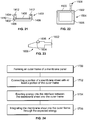
- FIG 21 illustrates a simplified cross-sectional view of a mold 1400 configured to form a membrane panel 1402, according to an embodiment of the present disclosure.
- the mold 1400 includes an internal chamber 1404 that is configured to receive liquid plastic, for example.
- a membrane sheet 1406 may be suspended within portions of the mold 1400 so that outer edges 1408 extend into the internal chamber 1404.
- Hot, liquid plastic 1410 is injected into the internal chamber 1404 through one or more inlets 1412.
- the liquid plastic 1410 flows around the outer edges 1408.
- the plastic securely fixes to the outer edges 1408.
- the membrane sheet 1406 may be integrally formed with the outer frame.
- the formed membrane panel 1402 may then be removed from the mold 1400.
- FIG 22 illustrates a simplified representation of a membrane sheet 1500 being integrated with an outer frame 1502 of a membrane panel 1504, according to an embodiment of the present disclosure.
- the outer frame 1502 may include an upstanding ridge 1506.
- the ridge 1506 may provide an energy director that is used to create a robust bond between the outer frame 1502 and the membrane sheet 1500.
- the ridge 1506 may be a small profile on the outer frame 1502 that is configured to direct and focus emitted energy thereto.
- the emitted energy securely bonds the outer frame 1502 to the ridge 1506, such as by melting portions of the membrane sheet 1500 to the ridge 1506, or vice versa.
- the membrane sheet 1500 may be integrally formed with the outer frame 1502.
- the outer frame 1502 may not include the ridge 1506.
- Figure 23 illustrates a lateral view of a connecting bracket 1600 of a membrane spacer 1602, according to an embodiment of the present disclosure.
- a channel 1604 may be formed in the connecting bracket 1600.
- the channel 1604 may retain a gasket 1606, which may be used to provide a sealing interface between the connecting bracket 1600 and a membrane panel.
- the channel 1604 and the gasket 1606 may be used with respect to any of the membrane spacers described above, such as those shown in Figures 3 , 14 , 15 , 17, 18, and 19 , for example.
- Figure 24 illustrates a flow chart of a method of forming a membrane panel, according to an embodiment of the present disclosure.
- the method may begin at 1700, in which an outer frame of the membrane panel is formed.
- an outer frame of the membrane panel is formed.
- brackets may be securely connected together to form the outer frame.
- the outer frame may be integrally molded and formed through injection-molding.
- a portion of a membrane sheet may be connected to at least a portion of the outer frame. 1700 and 1702 may simultaneously occur.
- a membrane sheet may be inserted into a mold, such that edge portions of the membrane sheet are positioned within an internal chamber of the mold. Injection-molded plastic may flow within the internal chamber around the edge portions.
- a membrane sheet may be positioned on top of or below an outer frame.
- energy is exerted into an interface between the membrane sheet and the outer frame.
- energy in the form of the heat of the injection-molded plastic may be exerted into the edge portions of the membrane sheet.
- the edge portions of the membrane sheet securely fix to the hardening plastic.
- energy in the form of ultrasonic, laser, heat, or other such energy may be focused into an interface between the outer frame and the membrane sheet to melt the edge portions to the outer frame, or vice versa.
- the membrane sheet is integrated into the outer frame through the exerted energy.
Landscapes
- Engineering & Computer Science (AREA)
- Physics & Mathematics (AREA)
- Thermal Sciences (AREA)
- Mechanical Engineering (AREA)
- General Engineering & Computer Science (AREA)
- Separation Using Semi-Permeable Membranes (AREA)
- Micromachines (AREA)
Claims (15)
- Membranplattenanordnung (100), welche konfiguriert ist, um innerhalb einer Energieaustauschanordnung (400, 500, 700) befestigt zu werden, wobei die Membranplattenanordnung umfasst:
zwei Membranplatten (802), welche jeweils Folgendes umfassen:einen Außenrahmen (101), welcher eine mittlere Öffnung definiert; undeine Membranfolie (102), welche mit dem Außenrahmen (101) integriert ist, wobei die Membranfolie (102) sich über die mittlere Öffnung erstreckt, und wobei die Membranfolie konfiguriert ist, um sensible Energie und latente Energie dadurch zu übertragen; und wobei die Membranplattenanordnung ferner umfasst:
einen Membranabstandshalter (900), welcher von den zwei Membranplatten (802) getrennt und zwischen diesen angeordnet ist, wobei der Membranabstandshalter (900) eine Verbindungsklammer (902) umfasst, welche konfiguriert ist, um zwischen den Ecken der Außenrahmen (101) der zwei Membranplatten (802) angeordnet zu werden, wobei die Verbindungsklammer (902) ein abgeschrägtes Ende (904) umfasst, welches eine distale Spitze (906) umfasst, welche sich mit einer Basis (908) über eine geneigte Fläche (910) verbindet. - Membranplattenanordnung nach Anspruch 1, wobei der Außenrahmen (101) um Randabschnitte der Membranfolie (102) herum spritzgegossen ist.
- Membranplattenanordnung nach einem der Ansprüche 1 bis 2, wobei die Membranfolie (102) an den Außenrahmen (101) durch Ultraschall gebunden ist.
- Membranplattenanordnung nach einem der Ansprüche 1 bis 2, wobei die Membranfolie (102) an den Außenrahmen (101) lasergebunden ist.
- Membranplattenanordnung nach einem der Ansprüche 1 bis 2, wobei die Membranfolie (102) an den Außenrahmen (101) heißversiegelt ist.
- Membranplattenanordnung nach einem der Ansprüche 1 bis 5, wobei der Außenrahmen (101) eine Mehrzahl von Klammern (104, 106) umfasst, welche innere Ränder aufweisen, welche die mittlere Öffnung definieren.
- Membranplattenanordnung nach Anspruch 6, wobei ein oder mehrere Abstandshalter-befestigende Merkmale (120) durch oder in mindestens einem der inneren Ränder geformt sind.
- Membranplattenanordnung nach einem der Ansprüche 1 bis 7, wobei der Außenrahmen (101) eine Mehrzahl von aufrechten Ecken (804) umfasst.
- Membranplattenanordnung nach einem der Ansprüche 1 bis 8, wobei die Membranfolie (102) mit dem Außenrahmen (101) ohne Klebstoff integriert ist.
- Membranplattenanordnung nach einem der Ansprüche 1 bis 9, wobei der Außenrahmen (101) zusammen mit mindestens einem getrennten Membranabstandshalter (200) zusammenpasst, um mindestens einen Luftflusskanal zu formen.
- Membranplattenanordnung nach einem der Ansprüche 1 bis 10, wobei der Außenrahmen (101) mit dem Membranabstandshalter einstückig gegossen und geformt ist.
- Energieaustauschanordnung, umfassend:
eine Mehrzahl von Membranplattenanordnungen, wobei jede der Mehrzahl von Membranplattenanordnungen nach einem der Ansprüche 1 bis 11 ist. - Energieaustauschanordnung nach Anspruch 12, wobei die Mehrzahl von Membranplatten eine erste Gruppe von Membranplatten und eine zweite Gruppe von Membranplatten umfasst, wobei die erste Gruppe von Membranplatten relativ zur zweiten Gruppe von Membranplatten senkrecht orientiert ist.
- Energieaustauschanordnung nach einem der Ansprüche 12 bis 13, wobei der Außenrahmen (101) mindestens eine geneigte Verbindungsklammer umfasst, welche konfiguriert ist, um mit einem Gegenmerkmal des einen der Mehrzahl von Abstandshaltern (200, 900) zusammenzupassen.
- Verfahren zum Formen einer Membranplattenanordnung (100), welche konfiguriert ist, um innerhalb einer Energieaustauschanordnung (400) befestigt zu werden, wobei das Verfahren umfasst:
Formen von zwei Membranplatten (802), wobei das Formen jeder Membranplatte umfasst:Formen eines Außenrahmens (101), welcher eine mittlere Öffnung definiert; undIntegrieren einer Membranfolie (102) mit dem Außenrahmen, wobei die poröse Membranfolie die mittlere Öffnung überspannt, und wobei die Membranfolie konfiguriert ist, um sensible Energie und latente Energie dadurch zu übertragen; und wobei das Verfahren ferner umfasst:
Formen eines Membranabstandshalters (900), welcher von den zwei Membranplatten (802) getrennt und zwischen diesen angeordnet ist, wobei der Membranabstandshalter (900) eine Verbindungsklammer (902) umfasst, welche konfiguriert ist, um zwischen Ecken der Außenrahmen (101) der zwei Membranplatten (802) angeordnet zu werden, wobei die Verbindungsklammer (902) ein abgeschrägtes Ende (904) umfasst, welches eine distale Spitze (906) aufweist, welche sich mit einer Basis (908) über eine geneigte Oberfläche (910) verbindet.
Priority Applications (1)
| Application Number | Priority Date | Filing Date | Title |
|---|---|---|---|
| EP20180081.0A EP3730892B1 (de) | 2013-03-14 | 2014-03-04 | In eine membran integrierte energieaustauschanordnung |
Applications Claiming Priority (3)
| Application Number | Priority Date | Filing Date | Title |
|---|---|---|---|
| US201361783048P | 2013-03-14 | 2013-03-14 | |
| US14/190,715 US10352628B2 (en) | 2013-03-14 | 2014-02-26 | Membrane-integrated energy exchange assembly |
| PCT/CA2014/000171 WO2014138860A1 (en) | 2013-03-14 | 2014-03-04 | Membrane-integrated energy exchange assembly |
Related Child Applications (1)
| Application Number | Title | Priority Date | Filing Date |
|---|---|---|---|
| EP20180081.0A Division EP3730892B1 (de) | 2013-03-14 | 2014-03-04 | In eine membran integrierte energieaustauschanordnung |
Publications (3)
| Publication Number | Publication Date |
|---|---|
| EP2972046A1 EP2972046A1 (de) | 2016-01-20 |
| EP2972046A4 EP2972046A4 (de) | 2016-11-30 |
| EP2972046B1 true EP2972046B1 (de) | 2020-06-17 |
Family
ID=51522209
Family Applications (2)
| Application Number | Title | Priority Date | Filing Date |
|---|---|---|---|
| EP14765396.8A Active EP2972046B1 (de) | 2013-03-14 | 2014-03-04 | In eine membran integrierte energieaustauschanordnung |
| EP20180081.0A Active EP3730892B1 (de) | 2013-03-14 | 2014-03-04 | In eine membran integrierte energieaustauschanordnung |
Family Applications After (1)
| Application Number | Title | Priority Date | Filing Date |
|---|---|---|---|
| EP20180081.0A Active EP3730892B1 (de) | 2013-03-14 | 2014-03-04 | In eine membran integrierte energieaustauschanordnung |
Country Status (7)
| Country | Link |
|---|---|
| US (2) | US10352628B2 (de) |
| EP (2) | EP2972046B1 (de) |
| CN (2) | CN107560482B (de) |
| AU (2) | AU2014231681B2 (de) |
| CA (1) | CA2901495C (de) |
| DK (1) | DK2972046T3 (de) |
| WO (1) | WO2014138860A1 (de) |
Cited By (8)
| Publication number | Priority date | Publication date | Assignee | Title |
|---|---|---|---|---|
| US10928082B2 (en) | 2011-09-02 | 2021-02-23 | Nortek Air Solutions Canada, Inc. | Energy exchange system for conditioning air in an enclosed structure |
| US11035618B2 (en) | 2012-08-24 | 2021-06-15 | Nortek Air Solutions Canada, Inc. | Liquid panel assembly |
| US11300364B2 (en) | 2013-03-14 | 2022-04-12 | Nortek Air Solutions Canada, Ine. | Membrane-integrated energy exchange assembly |
| US11598534B2 (en) | 2013-03-15 | 2023-03-07 | Nortek Air Solutions Canada, Inc. | Control system and method for a liquid desiccant air delivery system |
| US11892193B2 (en) | 2017-04-18 | 2024-02-06 | Nortek Air Solutions Canada, Inc. | Desiccant enhanced evaporative cooling systems and methods |
| EP4421923A1 (de) * | 2023-02-22 | 2024-08-28 | MANN+HUMMEL GmbH | Stapelplatte und stapelplattenvorrichtung für einen befeuchter |
| US12111072B2 (en) | 2010-06-24 | 2024-10-08 | Nortek Air Solutions Canada, Inc. | Liquid-to-air membrane energy exchanger |
| US12385654B2 (en) | 2017-04-18 | 2025-08-12 | Nortek Air Solutions Canada, Inc. | Systems and methods for managing conditions in enclosed space |
Families Citing this family (42)
| Publication number | Priority date | Publication date | Assignee | Title |
|---|---|---|---|---|
| WO2010129878A2 (en) | 2009-05-08 | 2010-11-11 | 7Solar Technologies, Inc. | Solar energy systems |
| ES2752069T3 (es) | 2010-05-25 | 2020-04-02 | 7Ac Tech Inc | Métodos y sistemas que utilizan desecantes líquidos para acondicionamiento de aire y otros procesos |
| US8915092B2 (en) | 2011-01-19 | 2014-12-23 | Venmar Ces, Inc. | Heat pump system having a pre-processing module |
| EP2672214A1 (de) | 2012-06-04 | 2013-12-11 | Alfa Laval Corporate AB | Endteil und Plattenwärmetauscher damit sowie Verfahren zur Herstellung solch eines Endteils |
| KR102189997B1 (ko) | 2012-06-11 | 2020-12-11 | 7에이씨 테크놀로지스, 아이엔씨. | 난류형 내식성 열 교환기들을 위한 방법들 및 시스템들 |
| WO2014089164A1 (en) | 2012-12-04 | 2014-06-12 | 7Ac Technologies, Inc. | Methods and systems for cooling buildings with large heat loads using desiccant chillers |
| EP2962043B1 (de) | 2013-03-01 | 2018-06-27 | 7AC Technologies, Inc. | Klimatisierungsystem mit trockenmittel |
| US9109808B2 (en) | 2013-03-13 | 2015-08-18 | Venmar Ces, Inc. | Variable desiccant control energy exchange system and method |
| US9772124B2 (en) | 2013-03-13 | 2017-09-26 | Nortek Air Solutions Canada, Inc. | Heat pump defrosting system and method |
| KR102099693B1 (ko) | 2013-03-14 | 2020-05-15 | 7에이씨 테크놀로지스, 아이엔씨. | 소형-분할형 액체 흡수제 공조 방법 및 시스템 |
| CN105121966B (zh) | 2013-03-14 | 2018-06-01 | 7Ac技术公司 | 用于液体干燥剂空气调节系统改造的方法和系统 |
| US11408681B2 (en) | 2013-03-15 | 2022-08-09 | Nortek Air Solations Canada, Iac. | Evaporative cooling system with liquid-to-air membrane energy exchanger |
| US9470426B2 (en) | 2013-06-12 | 2016-10-18 | 7Ac Technologies, Inc. | In-ceiling liquid desiccant air conditioning system |
| CN110594883B (zh) | 2014-03-20 | 2022-06-14 | 艾默生环境优化技术有限公司 | 组合热交换器和注水系统 |
| US9452383B2 (en) * | 2014-04-30 | 2016-09-27 | Uop Llc | Membrane separation element and process relating thereto |
| EP3183051B1 (de) | 2014-08-19 | 2020-04-29 | Nortek Air Solutions Canada, Inc. | Flüssigkeit-zu-luft-membranenergieaustauscher |
| WO2016081933A1 (en) | 2014-11-21 | 2016-05-26 | 7Ac Technologies, Inc. | Methods and systems for mini-split liquid desiccant air conditioning |
| CN107850335B (zh) | 2015-05-15 | 2021-02-19 | 北狄空气应对加拿大公司 | 利用液-气式膜能量交换器进行液体冷却 |
| US11092349B2 (en) | 2015-05-15 | 2021-08-17 | Nortek Air Solutions Canada, Inc. | Systems and methods for providing cooling to a heat load |
| EP3314188B1 (de) | 2015-06-26 | 2021-05-12 | Nortek Air Solutions Canada, Inc. | Flüssigkeit-zu-luft-membranenergieaustauscher mit drei fluiden |
| JP6728781B2 (ja) * | 2016-03-03 | 2020-07-22 | 株式会社Ihi | 反応装置 |
| AU2017228937A1 (en) | 2016-03-08 | 2018-10-25 | Nortek Air Solutions Canada, Inc. | Systems and methods for providing cooling to a heat load |
| CN111373202B (zh) | 2017-11-01 | 2021-11-26 | 艾默生环境优化技术有限公司 | 液体干燥剂空调系统中膜模块中液体干燥剂的均匀分布的方法和设备 |
| CN111448425A (zh) | 2017-11-01 | 2020-07-24 | 7Ac技术公司 | 用于液体干燥剂空调系统的储罐系统 |
| US11022330B2 (en) | 2018-05-18 | 2021-06-01 | Emerson Climate Technologies, Inc. | Three-way heat exchangers for liquid desiccant air-conditioning systems and methods of manufacture |
| JP7030036B2 (ja) * | 2018-09-11 | 2022-03-04 | 東邦瓦斯株式会社 | 熱交換器 |
| PL3877133T3 (pl) * | 2018-11-05 | 2025-08-04 | Zehnder Group International Ag | Sposób zapewniania bloku wymiennika ciepła z obudową |
| US20220178630A1 (en) * | 2019-02-27 | 2022-06-09 | Panasonic Intellectual Property Management Co., Ltd. | Heat exchange element and heat exchange-type ventilation device using same |
| WO2020206371A1 (en) * | 2019-04-05 | 2020-10-08 | Phase Change Energy Solutions, Inc. | Thermal management devices and methods |
| EP3926284B1 (de) * | 2019-04-05 | 2026-05-13 | Daikin Industries, Ltd. | Wärmetauscher |
| KR20220014890A (ko) | 2019-06-04 | 2022-02-07 | 벌티모어 에어코일 컴파니 인코포레이티드 | 튜브형 멤브레인 열교환기 |
| CN111001300B (zh) * | 2019-12-31 | 2022-03-25 | 广东栗子科技有限公司 | 一种高密封性电渗析膜堆的制备方法 |
| CA3189009A1 (en) * | 2020-08-21 | 2022-02-24 | Mitsubishi Electric Corporation | Heat exchangng element and heat exchange ventilator |
| EP4000721B1 (de) * | 2020-11-19 | 2026-01-07 | MAHLE International GmbH | Befeuchter |
| EP4255598A4 (de) | 2020-12-03 | 2025-01-15 | Baltimore Aircoil Company, Inc. | Rohrmembranwärmetauscher |
| EP4264158B1 (de) * | 2020-12-18 | 2026-03-18 | Nortek Air Solutions Canada, Inc. | Integriertes plattendesign |
| CN117213295A (zh) * | 2021-09-16 | 2023-12-12 | 青岛海信日立空调系统有限公司 | 全热交换器芯体及全热交换器 |
| JP7727888B2 (ja) * | 2021-12-09 | 2025-08-22 | パナソニックIpマネジメント株式会社 | 熱交換素子 |
| EP4215861B1 (de) * | 2022-01-21 | 2025-04-02 | HS Marston Aerospace Limited | Wärmetauscherkonstruktion |
| CN115751777A (zh) * | 2022-11-02 | 2023-03-07 | 新疆华奕新能源科技有限公司 | 一种薄膜式间接蒸发冷却器 |
| US20240200822A1 (en) * | 2022-12-15 | 2024-06-20 | Innergy Tech Inc. | Ventilation system |
| EP4705704A1 (de) * | 2023-05-05 | 2026-03-11 | Baltimore Aircoil Company, Inc. | Folienmembranvorrichtung |
Family Cites Families (329)
| Publication number | Priority date | Publication date | Assignee | Title |
|---|---|---|---|---|
| US2946201A (en) | 1960-07-26 | Method for avoiding frost deposits on cooling members | ||
| US1015831A (en) | 1911-02-27 | 1912-01-30 | Eduard Pielock | Heat-exchanging device. |
| US2186844A (en) | 1935-05-31 | 1940-01-09 | Gen Motors Corp | Refrigerating apparatus |
| CH193732A (de) | 1935-07-10 | 1937-10-31 | Hans Dr Behringer | Vorrichtung, in welcher strömende Medien zur Durchführung einer isobaren thermodynamischen Zustandsänderung in Berührung mit Wänden gebracht werden. |
| US2290465A (en) | 1939-04-20 | 1942-07-21 | Robert B P Crawford | Air conditioning system |
| US2562811A (en) | 1945-09-15 | 1951-07-31 | Muffly Glenn | Refrigerator |
| US3009684A (en) | 1954-10-26 | 1961-11-21 | Munters Carl Georg | Apparatus and method of conditioning the stream of incoming air by the thermodynamic exchange with separate streams of other air |
| US2968165A (en) | 1955-12-22 | 1961-01-17 | Norback Per Gunnar | Air conditioning method and apparatus |
| US3018231A (en) | 1957-10-22 | 1962-01-23 | Midland Ross Corp | Air conditioning for remote spaces |
| US3144901A (en) | 1960-05-13 | 1964-08-18 | Lizenzia A G | Movable air conditioning apparatus |
| US3247679A (en) | 1964-10-08 | 1966-04-26 | Lithonia Lighting Inc | Integrated comfort conditioning system |
| US3291206A (en) | 1965-09-13 | 1966-12-13 | Nicholson Terence Peter | Heat exchanger plate |
| US3467072A (en) | 1966-08-31 | 1969-09-16 | Energy Transform | Combustion optimizing devices and methods |
| US3401530A (en) | 1966-12-19 | 1968-09-17 | Lithonia Lighting Inc | Comfort conditioning system |
| GB1354502A (en) | 1970-08-28 | 1974-06-05 | Ici Ltd | Heat exchangers |
| US3735559A (en) | 1972-02-02 | 1973-05-29 | Gen Electric | Sulfonated polyxylylene oxide as a permselective membrane for water vapor transport |
| US4113004A (en) | 1974-11-04 | 1978-09-12 | Gas Developments Corporation | Air conditioning process |
| US4011731A (en) | 1974-11-15 | 1977-03-15 | Gershon Meckler | Air conditioning apparatus utilizing solar energy and method |
| US4180985A (en) | 1977-12-01 | 1980-01-01 | Northrup, Incorporated | Air conditioning system with regeneratable desiccant bed |
| US4173924A (en) | 1978-03-01 | 1979-11-13 | Schweitzer Industrial Corporation | Paint spray booth with air supply system |
| US4235081A (en) | 1978-10-31 | 1980-11-25 | Kellogg-American, Inc. | Compressed air dryer |
| US4233796A (en) | 1978-11-22 | 1980-11-18 | Ppg Industries, Inc. | Desiccated spandrel panels |
| US4257169A (en) | 1978-12-11 | 1981-03-24 | Jack Pierce | Commodity dryer |
| US4259849A (en) | 1979-02-15 | 1981-04-07 | Midland-Ross Corporation | Chemical dehumidification system which utilizes a refrigeration unit for supplying energy to the system |
| US4287661A (en) | 1980-03-26 | 1981-09-08 | International Business Machines Corporation | Method for making an improved polysilicon conductor structure utilizing reactive-ion etching and thermal oxidation |
| DE3107010C2 (de) * | 1981-02-25 | 1985-02-28 | Dieter Christian Steinegg-Appenzell Steeb | Metallkühler zum Kühlen eines unter hohem Druck durchströmenden Fluids durch Luft |
| US4373347A (en) | 1981-04-02 | 1983-02-15 | Board Of Regents, University Of Texas System | Hybrid double-absorption cooling system |
| US4380910A (en) | 1981-08-13 | 1983-04-26 | Aztech International, Ltd. | Multi-stage indirect-direct evaporative cooling process and apparatus |
| US4430864A (en) | 1981-12-31 | 1984-02-14 | Midwest Research Institute | Hybrid vapor compression and desiccant air conditioning system |
| IL64915A (en) | 1982-02-02 | 1985-04-30 | Joel Harband | Apparatus and method for temperature and humidity control |
| US4538426A (en) | 1983-09-12 | 1985-09-03 | Bock Sumner D | Air cooling system |
| DE3521914A1 (de) | 1984-06-20 | 1986-01-02 | Showa Aluminum Corp., Sakai, Osaka | Waermetauscher in fluegelplattenbauweise |
| JPH0610587B2 (ja) | 1984-08-22 | 1994-02-09 | 三菱電機株式会社 | 熱交換器 |
| US4594860A (en) | 1984-09-24 | 1986-06-17 | American Solar King Corporation | Open cycle desiccant air-conditioning system and components thereof |
| US5131238A (en) | 1985-04-03 | 1992-07-21 | Gershon Meckler | Air conditioning apparatus |
| US5181387A (en) | 1985-04-03 | 1993-01-26 | Gershon Meckler | Air conditioning apparatus |
| US4723417A (en) | 1985-08-05 | 1988-02-09 | Camp Dresser And Mckee Inc. | Dehumidification apparatus |
| US4729774A (en) | 1986-03-10 | 1988-03-08 | Gas Research Institute | Nonuniform regeneration system for desiccant bed |
| US4700550A (en) | 1986-03-10 | 1987-10-20 | Rhodes Barry V | Enthalpic heat pump desiccant air conditioning system |
| US4719761A (en) | 1986-05-30 | 1988-01-19 | Cromer Charles J | Cooling system |
| US5020335A (en) | 1986-07-09 | 1991-06-04 | Walter F. Albers | Method and apparatus for simultaneous heat and mass transfer |
| US4691530A (en) | 1986-09-05 | 1987-09-08 | Milton Meckler | Cogeneration and central regeneration multi-contactor air conditioning system |
| JPH068703B2 (ja) | 1987-11-13 | 1994-02-02 | 株式会社東芝 | 空気調和装置 |
| US4841733A (en) | 1988-01-07 | 1989-06-27 | Dussault David R | Dri-Pc humidity and temperature controller |
| EP0326083B1 (de) | 1988-01-26 | 1994-06-01 | Asahi Glass Company Ltd. | Für Dampf permselektive Membran |
| US5003961A (en) | 1988-02-05 | 1991-04-02 | Besik Ferdinand K | Apparatus for ultra high energy efficient heating, cooling and dehumidifying of air |
| US4982575A (en) | 1988-02-05 | 1991-01-08 | Besik Ferdinand K | Apparatus and a method for ultra high energy efficient dehumidification and cooling of air |
| US4900448A (en) | 1988-03-29 | 1990-02-13 | Honeywell Inc. | Membrane dehumidification |
| GB8817793D0 (en) | 1988-07-26 | 1988-09-01 | British Petroleum Co Plc | Mixing apparatus |
| US4905479A (en) | 1989-01-27 | 1990-03-06 | Gas Research Institute | Hybrid air conditioning system |
| US4887438A (en) | 1989-02-27 | 1989-12-19 | Milton Meckler | Desiccant assisted air conditioner |
| US4939906A (en) | 1989-06-09 | 1990-07-10 | Gas Research Institute | Multi-stage boiler/regenerator for liquid desiccant dehumidifiers |
| US4930322A (en) | 1989-09-11 | 1990-06-05 | The United States Of America As Represented By The Secretary Of The Navy | Advanced heat pump |
| US4941324A (en) | 1989-09-12 | 1990-07-17 | Peterson John L | Hybrid vapor-compression/liquid desiccant air conditioner |
| US5020334A (en) | 1990-02-23 | 1991-06-04 | Gas Research Institute | Localized air dehumidification system |
| DE4009556C2 (de) | 1990-03-24 | 1994-07-07 | Schmid Christoph | Wärmeübertrager |
| US5373704A (en) | 1990-04-17 | 1994-12-20 | Arthur D. Little, Inc. | Desiccant dehumidifier |
| US5022241A (en) | 1990-05-04 | 1991-06-11 | Gas Research Institute | Residential hybrid air conditioning system |
| US5148374A (en) | 1990-06-19 | 1992-09-15 | Icc Technologies, Inc. | Desiccant space conditioning control system and method |
| WO1992001892A1 (en) | 1990-07-20 | 1992-02-06 | Alberni Thermodynamics Ltd. | Heating and cooling system for air space in a building |
| CH682721A5 (de) | 1991-01-17 | 1993-11-15 | Galipag | Verfahren für den Stoffaustausch zwischen flüssigen und gasförmigen Medien. |
| US5749230A (en) | 1991-01-18 | 1998-05-12 | Engelhard/Icc | Method for creating a humidity gradient within an air conditioned zone |
| US5176005A (en) | 1991-06-24 | 1993-01-05 | Baltimore Aircoil Company | Method of conditioning air with a multiple staged desiccant based system |
| US5170633A (en) | 1991-06-24 | 1992-12-15 | Amsted Industries Incorporated | Desiccant based air conditioning system |
| US5297398A (en) | 1991-07-05 | 1994-03-29 | Milton Meckler | Polymer desiccant and system for dehumidified air conditioning |
| US5191771A (en) | 1991-07-05 | 1993-03-09 | Milton Meckler | Polymer desiccant and system for dehumidified air conditioning |
| US5471852A (en) | 1991-07-05 | 1995-12-05 | Meckler; Milton | Polymer enhanced glycol desiccant heat-pipe air dehumidifier preconditioning system |
| US5758511A (en) | 1991-10-15 | 1998-06-02 | Yoho; Robert W. | Desiccant multi-duel hot air/water air conditioning system |
| US5353606A (en) | 1991-10-15 | 1994-10-11 | Yoho Robert W | Desiccant multi-fuel hot air/water air conditioning unit |
| JPH05157282A (ja) | 1991-12-05 | 1993-06-22 | Fujita Corp | 建築物用空調外気処理システム |
| US5325676A (en) | 1992-08-24 | 1994-07-05 | Milton Meckler | Desiccant assisted multi-use air pre-conditioner unit with system heat recovery capability |
| US5351497A (en) | 1992-12-17 | 1994-10-04 | Gas Research Institute | Low-flow internally-cooled liquid-desiccant absorber |
| US5401706A (en) | 1993-01-06 | 1995-03-28 | Semco Incorporated | Desiccant-coated substrate and method of manufacture |
| US5649428A (en) | 1993-01-08 | 1997-07-22 | Engelhard/Icc | Hybrid air-conditioning system with improved recovery evaporator and subcool condenser coils |
| US5579647A (en) | 1993-01-08 | 1996-12-03 | Engelhard/Icc | Desiccant assisted dehumidification and cooling system |
| US5551245A (en) | 1995-01-25 | 1996-09-03 | Engelhard/Icc | Hybrid air-conditioning system and method of operating the same |
| US5448895A (en) | 1993-01-08 | 1995-09-12 | Engelhard/Icc | Hybrid heat pump and desiccant space conditioning system and control method |
| US5564281A (en) | 1993-01-08 | 1996-10-15 | Engelhard/Icc | Method of operating hybrid air-conditioning system with fast condensing start-up |
| CA2100734C (en) | 1993-07-16 | 1998-05-26 | Normand Verret | Heat exchanger for dusty environment |
| JPH07133994A (ja) | 1993-11-09 | 1995-05-23 | Japan Gore Tex Inc | 熱交換膜 |
| TW255835B (en) | 1994-01-07 | 1995-09-01 | Kubota Kk | Filtration membrane module |
| US7231967B2 (en) | 1994-01-31 | 2007-06-19 | Building Performance Equipment, Inc. | Ventilator system and method |
| US5528905A (en) | 1994-03-25 | 1996-06-25 | Essex Invention S.A. | Contactor, particularly a vapour exchanger for the control of the air hygrometric content, and a device for air handling |
| US5502975A (en) | 1994-06-01 | 1996-04-02 | Munters Corporation | Air conditioning system |
| TW245768B (en) | 1994-06-20 | 1995-04-21 | Engelhard Icc | Method for killing microorganisms |
| US5526651A (en) | 1994-07-15 | 1996-06-18 | Gas Research Institute | Open cycle desiccant cooling systems |
| US5826641A (en) | 1994-10-27 | 1998-10-27 | Aaon, Inc. | Air conditioner with heat wheel |
| US5542968A (en) | 1995-01-24 | 1996-08-06 | Laroche Industries, Inc. | Enthalphy Wheel |
| US5517828A (en) | 1995-01-25 | 1996-05-21 | Engelhard/Icc | Hybrid air-conditioning system and method of operating the same |
| US5638900A (en) | 1995-01-27 | 1997-06-17 | Ail Research, Inc. | Heat exchange assembly |
| US5580369A (en) | 1995-01-30 | 1996-12-03 | Laroche Industries, Inc. | Adsorption air conditioning system |
| US5653115A (en) | 1995-04-12 | 1997-08-05 | Munters Corporation | Air-conditioning system using a desiccant core |
| US6018954A (en) | 1995-04-20 | 2000-02-01 | Assaf; Gad | Heat pump system and method for air-conditioning |
| US5661983A (en) | 1995-06-02 | 1997-09-02 | Energy International, Inc. | Fluidized bed desiccant cooling system |
| US5685897A (en) | 1995-07-06 | 1997-11-11 | Laroche Industries, Inc. | High strength, low pressure drop adsorbent wheel |
| US5650221A (en) | 1995-07-06 | 1997-07-22 | Laroche Industries, Inc. | High strength, low pressure drop sensible and latent heat exchange wheel |
| US5911273A (en) | 1995-08-01 | 1999-06-15 | Behr Gmbh & Co. | Heat transfer device of a stacked plate construction |
| DE19528117B4 (de) | 1995-08-01 | 2004-04-29 | Behr Gmbh & Co. | Wärmeübertrager mit Plattenstapelaufbau |
| JP3322292B2 (ja) | 1995-10-23 | 2002-09-09 | 日立電線株式会社 | 伝熱管 |
| US5791153A (en) | 1995-11-09 | 1998-08-11 | La Roche Industries Inc. | High efficiency air conditioning system with humidity control |
| US5826434A (en) | 1995-11-09 | 1998-10-27 | Novelaire Technologies, L.L.C. | High efficiency outdoor air conditioning system |
| JPH09173758A (ja) | 1995-12-21 | 1997-07-08 | Toho Kako Kensetsu Kk | 高沸点溶剤回収装置 |
| US5761923A (en) | 1996-01-12 | 1998-06-09 | Ebara Corporation | Air conditioning system |
| US5816065A (en) | 1996-01-12 | 1998-10-06 | Ebara Corporation | Desiccant assisted air conditioning system |
| JP3585308B2 (ja) | 1996-01-12 | 2004-11-04 | 株式会社荏原製作所 | デシカント空調装置 |
| US5791157A (en) | 1996-01-16 | 1998-08-11 | Ebara Corporation | Heat pump device and desiccant assisted air conditioning system |
| US5832736A (en) | 1996-01-16 | 1998-11-10 | Orion Machinery Co., Ltd. | Disk heat exchanger , and a refrigeration system including the same |
| CN1110682C (zh) | 1996-01-16 | 2003-06-04 | 奥里恩机械株式会社 | 热交换器 |
| US5758508A (en) | 1996-02-05 | 1998-06-02 | Larouche Industries Inc. | Method and apparatus for cooling warm moisture-laden air |
| US6018953A (en) | 1996-02-12 | 2000-02-01 | Novelaire Technologies, L.L.C. | Air conditioning system having indirect evaporative cooler |
| US5727394A (en) | 1996-02-12 | 1998-03-17 | Laroche Industries, Inc. | Air conditioning system having improved indirect evaporative cooler |
| US5660048A (en) | 1996-02-16 | 1997-08-26 | Laroche Industries, Inc. | Air conditioning system for cooling warm moisture-laden air |
| JPH09318127A (ja) | 1996-05-24 | 1997-12-12 | Ebara Corp | 空調システム |
| US5860284A (en) | 1996-07-19 | 1999-01-19 | Novel Aire Technologies, L.L.C. | Thermally regenerated desiccant air conditioner with indirect evaporative cooler |
| US5732562A (en) | 1996-08-13 | 1998-03-31 | Moratalla; Jose M. | Method and apparatus for regenerating desiccants in a closed cycle |
| US6029467A (en) | 1996-08-13 | 2000-02-29 | Moratalla; Jose M. | Apparatus for regenerating desiccants in a closed cycle |
| JPH10170177A (ja) | 1996-08-31 | 1998-06-26 | Behr Gmbh & Co | プレートパイル構造を有する熱交換器とその製造方法 |
| JPH1096542A (ja) | 1996-09-24 | 1998-04-14 | Ebara Corp | 空調システム |
| US6079481A (en) | 1997-01-23 | 2000-06-27 | Ail Research, Inc | Thermal storage system |
| DE19802604A1 (de) | 1997-01-27 | 1998-08-06 | Int Rectifier Corp | Motor-Steuergeräteschaltung |
| US5761915A (en) | 1997-03-12 | 1998-06-09 | Fedders Corporation | Method and apparatus for supplying conditioned fresh air to an indoor area |
| CN1236258C (zh) | 1997-03-25 | 2006-01-11 | 株式会社荏原制作所 | 空调系统 |
| US6405543B2 (en) | 1997-05-16 | 2002-06-18 | Work Smart Energy Enterprises Inc. | High-efficiency air-conditioning system with high-volume air distribution |
| US6176101B1 (en) | 1997-06-18 | 2001-01-23 | Gas Research Institute | Flat-plate absorbers and evaporators for absorption coolers |
| AUPO783697A0 (en) | 1997-07-10 | 1997-07-31 | Shaw, Allan | A low energy high performance variable coolant temperature air conditioning system |
| US6029462A (en) | 1997-09-09 | 2000-02-29 | Denniston; James G. T. | Desiccant air conditioning for a motorized vehicle |
| JP2971843B2 (ja) | 1997-10-09 | 1999-11-08 | 株式会社荏原製作所 | 除湿空調装置 |
| US5931016A (en) | 1997-10-13 | 1999-08-03 | Advanced Thermal Technologies, Llc | Air conditioning system having multiple energy regeneration capabilities |
| WO1999026025A1 (en) | 1997-11-16 | 1999-05-27 | Drykor Ltd. | Dehumidifier system |
| IL141579A0 (en) | 2001-02-21 | 2002-03-10 | Drykor Ltd | Dehumidifier/air-conditioning system |
| US6138470A (en) | 1997-12-04 | 2000-10-31 | Fedders Corporation | Portable liquid desiccant dehumidifier |
| US5946931A (en) | 1998-02-25 | 1999-09-07 | The United States Of America As Represented By The Administrator Of The National Aeronautics And Space Administration | Evaporative cooling membrane device |
| US5992160A (en) | 1998-05-11 | 1999-11-30 | Carrier Corporation | Make-up air energy recovery ventilator |
| WO2000000774A1 (en) | 1998-06-30 | 2000-01-06 | Ebara Corporation | Heat exchanger, heat pump, dehumidifier, and dehumidifying method |
| US6145588A (en) | 1998-08-03 | 2000-11-14 | Xetex, Inc. | Air-to-air heat and moisture exchanger incorporating a composite material for separating moisture from air technical field |
| JP2000062446A (ja) | 1998-08-20 | 2000-02-29 | Zexel Corp | 車両用空調装置 |
| US6156102A (en) | 1998-11-10 | 2000-12-05 | Fantom Technologies Inc. | Method and apparatus for recovering water from air |
| US6094835A (en) | 1998-12-14 | 2000-08-01 | University Of Central Florida | Heat pump dryer with desciccant enhanced moisture removal |
| US6720990B1 (en) | 1998-12-28 | 2004-04-13 | Walker Digital, Llc | Internet surveillance system and method |
| US6178762B1 (en) | 1998-12-29 | 2001-01-30 | Ethicool Air Conditioners, Inc. | Desiccant/evaporative cooling system |
| US6363218B1 (en) | 1999-01-15 | 2002-03-26 | Ail Research, Inc. | Liquid heater load control |
| US6199388B1 (en) | 1999-03-10 | 2001-03-13 | Semco Incorporated | System and method for controlling temperature and humidity |
| BR0008997A (pt) | 1999-03-14 | 2002-01-08 | Drykor Ltd | Sistema de condicionamento de ar e desumidificador para controlar o ambiente de uma área controlada e sistema desumidificador |
| CA2283089C (en) | 1999-05-10 | 2004-05-25 | Mitsubishi Denki Kabushiki Kaisha | Heat exchanger and method for preparing it |
| US6237354B1 (en) | 1999-10-27 | 2001-05-29 | Charles J. Cromer | Cooling system |
| CA2390682C (en) | 1999-11-05 | 2007-05-01 | David A. Thompson | Enthalpy pump |
| US6684649B1 (en) | 1999-11-05 | 2004-02-03 | David A. Thompson | Enthalpy pump |
| US6141979A (en) | 1999-11-19 | 2000-11-07 | American Standard Inc. | Dual heat exchanger wheels with variable speed |
| US6575228B1 (en) | 2000-03-06 | 2003-06-10 | Mississippi State Research And Technology Corporation | Ventilating dehumidifying system |
| US6864005B2 (en) | 2000-03-08 | 2005-03-08 | Ballard Power Systems Inc. | Membrane exchange humidifier for a fuel cell |
| US6875247B2 (en) | 2000-06-06 | 2005-04-05 | Battelle Memorial Institute | Conditions for fluid separations in microchannels, capillary-driven fluid separations, and laminated devices capable of separating fluids |
| DE10028030A1 (de) | 2000-06-09 | 2001-12-13 | Zeolith Tech | Sorptionsvorrichtung zum Heizen und Kühlen von Gasströmen |
| US6568466B2 (en) | 2000-06-23 | 2003-05-27 | Andrew Lowenstein | Heat exchange assembly |
| US6962662B2 (en) | 2000-07-13 | 2005-11-08 | Stephen Ray Wurzburger | Process for treating lightly contaminated acid mine water |
| US6497107B2 (en) | 2000-07-27 | 2002-12-24 | Idalex Technologies, Inc. | Method and apparatus of indirect-evaporation cooling |
| WO2002038257A2 (en) | 2000-11-13 | 2002-05-16 | Mcmaster University | Gas separation device |
| US6739142B2 (en) | 2000-12-04 | 2004-05-25 | Amos Korin | Membrane desiccation heat pump |
| US6820682B2 (en) | 2000-12-19 | 2004-11-23 | Denso Corporation | Heat exchanger |
| EP1347260B1 (de) | 2000-12-25 | 2009-06-10 | Honda Giken Kogyo Kabushiki Kaisha | Wärmetauscher |
| US6711907B2 (en) | 2001-02-28 | 2004-03-30 | Munters Corporation | Desiccant refrigerant dehumidifier systems |
| US6841601B2 (en) | 2001-03-13 | 2005-01-11 | Dais-Analytic Corporation | Crosslinked polymer electrolyte membranes for heat and moisture exchange devices |
| CN1180205C (zh) | 2001-05-16 | 2004-12-15 | 株式会社荏原制作所 | 除湿装置 |
| US6598862B2 (en) | 2001-06-20 | 2003-07-29 | Evapco International, Inc. | Evaporative cooler |
| IL144119A (en) | 2001-07-03 | 2006-07-05 | Gad Assaf | Air conditioning system |
| US6800118B2 (en) | 2001-07-17 | 2004-10-05 | Gore Enterprise Holdings, Inc. | Gas/liquid separation devices |
| US6854278B2 (en) | 2001-08-20 | 2005-02-15 | Valeriy Maisotsenko | Method of evaporative cooling of a fluid and apparatus therefor |
| US20030037905A1 (en) | 2001-08-22 | 2003-02-27 | Kuo-Liang Weng | Air conditioning system performing composite heat transfer through change of water two phases (liquid vapor) |
| DE10143092A1 (de) | 2001-09-03 | 2003-03-20 | Att Automotivethermotech Gmbh | Gegenstromwärmetauscher mit thermischer Schichtung zur Kabinenbeheizung von Kraftfahrzeugen |
| US7150314B2 (en) | 2001-09-17 | 2006-12-19 | American Standard International Inc. | Dual exhaust energy recovery system |
| US6932909B2 (en) | 2002-01-15 | 2005-08-23 | Kroff Chemical Company, Inc. | Method of treating mine drainage |
| US6848265B2 (en) | 2002-04-24 | 2005-02-01 | Ail Research, Inc. | Air conditioning system |
| US6532763B1 (en) | 2002-05-06 | 2003-03-18 | Carrier Corporation | Evaporator with mist eliminator |
| US20060191677A1 (en) | 2002-05-10 | 2006-08-31 | Viczena George S | Control of air conditioning cooling or heating coil |
| US6751964B2 (en) | 2002-06-28 | 2004-06-22 | John C. Fischer | Desiccant-based dehumidification system and method |
| US20040061245A1 (en) | 2002-08-05 | 2004-04-01 | Valeriy Maisotsenko | Indirect evaporative cooling mechanism |
| TWI271499B (en) | 2002-08-15 | 2007-01-21 | Velocys Inc | Process for cooling a product in a heat exchanger employing microchannels |
| US6622519B1 (en) | 2002-08-15 | 2003-09-23 | Velocys, Inc. | Process for cooling a product in a heat exchanger employing microchannels for the flow of refrigerant and product |
| JP2004116419A (ja) | 2002-09-26 | 2004-04-15 | Toshiba Corp | 排気ガス熱利用システム |
| IL152885A0 (en) | 2002-11-17 | 2003-06-24 | Agam Energy Systems Ltd | Air conditioning systems and methods |
| KR100504503B1 (ko) | 2003-01-14 | 2005-08-01 | 엘지전자 주식회사 | 공기조화시스템 |
| KR100463550B1 (ko) | 2003-01-14 | 2004-12-29 | 엘지전자 주식회사 | 냉난방시스템 |
| CA2416508C (en) | 2003-01-17 | 2008-11-18 | Martin Gagnon | A stackable energy transfer core spacer |
| JP2004239544A (ja) | 2003-02-07 | 2004-08-26 | Yazaki Corp | 吸収式冷温水機 |
| WO2004072560A1 (de) | 2003-02-14 | 2004-08-26 | Hombuecher Heinz-Dieter | Verfahren und vorrichtung zur energierückgewinnung |
| JP3835413B2 (ja) | 2003-02-24 | 2006-10-18 | 株式会社日立プラントテクノロジー | 除湿空調装置 |
| US7306650B2 (en) | 2003-02-28 | 2007-12-11 | Midwest Research Institute | Using liquid desiccant as a regenerable filter for capturing and deactivating contaminants |
| US6709492B1 (en) | 2003-04-04 | 2004-03-23 | United Technologies Corporation | Planar membrane deoxygenator |
| JP4454580B2 (ja) | 2003-05-30 | 2010-04-21 | 旭化成ケミカルズ株式会社 | 加湿装置 |
| US7322205B2 (en) | 2003-09-12 | 2008-01-29 | Davis Energy Group, Inc. | Hydronic rooftop cooling systems |
| EP1521040B1 (de) | 2003-10-01 | 2006-11-29 | Imes Management AG | Vorrichtung zur Entfeuchtung von Raumluft |
| US7093649B2 (en) | 2004-02-10 | 2006-08-22 | Peter Dawson | Flat heat exchanger plate and bulk material heat exchanger using the same |
| US7093452B2 (en) | 2004-03-24 | 2006-08-22 | Acma Limited | Air conditioner |
| US7181918B2 (en) | 2004-03-25 | 2007-02-27 | Oxycell Holding B.V. | Vehicle cooler |
| CN1997861A (zh) | 2004-04-09 | 2007-07-11 | 艾尔研究公司 | 热质交换器 |
| WO2005100243A1 (en) | 2004-04-15 | 2005-10-27 | Suuri Kulta Ab | A process for the removal of thiocyanate from effluent |
| US7559356B2 (en) | 2004-04-19 | 2009-07-14 | Eksident Technologies, Inc. | Electrokinetic pump driven heat transfer system |
| US7781034B2 (en) | 2004-05-04 | 2010-08-24 | Sigma Laboratories Of Arizona, Llc | Composite modular barrier structures and packages |
| US6973795B1 (en) | 2004-05-27 | 2005-12-13 | American Standard International Inc. | HVAC desiccant wheel system and method |
| KR100607204B1 (ko) | 2004-06-18 | 2006-08-01 | (주) 위젠글로벌 | 냉각유체의 증발 냉각방법 및 그 장치 |
| IL163015A (en) | 2004-07-14 | 2009-07-20 | Gad Assaf | Systems and methods for dehumidification |
| US7753991B2 (en) | 2004-07-30 | 2010-07-13 | Kertzman Systems, Inc. | Water transport method and assembly including a thin film membrane for the addition or removal of water from gases or liquids |
| US20060205301A1 (en) | 2005-03-11 | 2006-09-14 | Bha Technologies, Inc. | Composite membrane having hydrophilic properties and method of manufacture |
| JP3879763B2 (ja) | 2005-03-31 | 2007-02-14 | ダイキン工業株式会社 | 調湿装置 |
| CN2821506Y (zh) * | 2005-06-24 | 2006-09-27 | 广东国得科技发展有限公司 | 一种空调系统全热交换器 |
| TWI326691B (en) | 2005-07-22 | 2010-07-01 | Kraton Polymers Res Bv | Sulfonated block copolymers, method for making same, and various uses for such block copolymers |
| US7309062B2 (en) | 2005-08-05 | 2007-12-18 | Wen-Feng Lin | Fixed wet type dehumidification and energy recovery device |
| WO2007030747A2 (en) | 2005-09-09 | 2007-03-15 | Tangenx Technology Corporation | Laminated cassette device and methods for making same |
| DE202006009464U1 (de) | 2005-09-23 | 2006-09-14 | Pierburg Gmbh | Wärmetauscher |
| JP2007285691A (ja) * | 2006-03-22 | 2007-11-01 | Matsushita Electric Ind Co Ltd | 熱交換器 |
| WO2007119394A1 (ja) | 2006-03-22 | 2007-10-25 | Matsushita Electric Industrial Co., Ltd. | 熱交換器とその製造方法 |
| JP4770534B2 (ja) | 2006-03-22 | 2011-09-14 | パナソニック株式会社 | 熱交換器 |
| JP2007285598A (ja) | 2006-04-17 | 2007-11-01 | Matsushita Electric Ind Co Ltd | 熱交換器 |
| US7411785B2 (en) | 2006-06-05 | 2008-08-12 | Cray Inc. | Heat-spreading devices for cooling computer systems and associated methods of use |
| US20080023182A1 (en) | 2006-07-25 | 2008-01-31 | Henry Earl Beamer | Dual mode heat exchanger assembly |
| TWI404897B (zh) | 2006-08-25 | 2013-08-11 | Ducool Ltd | 用以管理流體中之水含量的系統及方法 |
| US20080066888A1 (en) | 2006-09-08 | 2008-03-20 | Danaher Motion Stockholm Ab | Heat sink |
| JP2008070046A (ja) | 2006-09-14 | 2008-03-27 | Matsushita Electric Ind Co Ltd | 熱交換素子 |
| WO2008037079A1 (en) | 2006-09-29 | 2008-04-03 | Dpoint Technologies Inc. | Pleated heat and humidity exchanger with flow field elements |
| EP1921702A1 (de) | 2006-11-10 | 2008-05-14 | DSMIP Assets B.V. | Befeuchtungsmembran |
| CN200958820Y (zh) | 2006-10-12 | 2007-10-10 | 广东省吉荣空调设备公司 | 动态高温蓄冷空调机 |
| US7389652B1 (en) | 2006-10-21 | 2008-06-24 | Shields Fair | Heat transfer apparatus |
| KR101180041B1 (ko) | 2006-10-31 | 2012-09-05 | 한라공조주식회사 | 히터코어 및 상기 히터코어가 장착된 자동차용 공조장치 |
| US20080162198A1 (en) | 2007-01-03 | 2008-07-03 | Cisco Technology, Inc. | Method and System for Conference Room Scheduling |
| EP2109495A4 (de) | 2007-01-20 | 2011-09-28 | Dais Analytic Corp | Selektiver mehrphasiger massentransfer durch eine membran |
| RU2458303C2 (ru) | 2007-05-09 | 2012-08-10 | Мкнннак Энерджи Сервисез Инк. | Система охлаждения |
| KR20100028025A (ko) | 2007-05-30 | 2010-03-11 | 문터스 코포레이션 | 건조 장치를 사용하는 습기 제어 시스템 |
| FI20075595A0 (fi) | 2007-06-27 | 2007-08-30 | Enervent Oy Ab | Ilmanvaihtokojeyksikkö |
| US8318824B2 (en) | 2007-07-27 | 2012-11-27 | Asahi Kasei Chemicals Corporation | Hydrophilic polyolefin sintered body |
| CA122381S (en) | 2007-09-19 | 2009-05-28 | Venmar Ventillation Inc | Louvered air ventilation grille |
| US8268060B2 (en) | 2007-10-15 | 2012-09-18 | Green Comfort Systems, Inc. | Dehumidifier system |
| US20090126913A1 (en) | 2007-11-16 | 2009-05-21 | Davis Energy Group, Inc. | Vertical counterflow evaporative cooler |
| US7963119B2 (en) | 2007-11-26 | 2011-06-21 | International Business Machines Corporation | Hybrid air and liquid coolant conditioning unit for facilitating cooling of one or more electronics racks of a data center |
| CN101469090B (zh) | 2007-12-27 | 2011-06-08 | Tcl集团股份有限公司 | 高分子改性膜材料及使用此材料的空调器 |
| PL2304326T3 (pl) | 2008-01-14 | 2019-05-31 | Core Energy Recovery Solutions Inc | Membranowe wkłady harmonijkowe-krzyżowe i sposób wytwarzania membranowych wkładów harmonijkowych-krzyżowych |
| EP2250446B1 (de) | 2008-01-25 | 2020-02-19 | Alliance for Sustainable Energy, LLC | Indirekter verdunstungskühler |
| JP2011512507A (ja) | 2008-02-14 | 2011-04-21 | マンターズ コーポレイション | エネルギー回収強化型冷却機再生乾燥剤冷媒除湿装置 |
| US20090211977A1 (en) | 2008-02-27 | 2009-08-27 | Oregon State University | Through-plate microchannel transfer devices |
| CN201203217Y (zh) | 2008-04-14 | 2009-03-04 | 西安工程大学 | 一种四级蒸发冷却组合式空调机组 |
| JP2009275955A (ja) | 2008-05-13 | 2009-11-26 | Sanwa System Kk | デシカント空調装置 |
| US8079508B2 (en) | 2008-05-30 | 2011-12-20 | Foust Harry D | Spaced plate heat exchanger |
| JP5156504B2 (ja) | 2008-06-25 | 2013-03-06 | 日本ゴア株式会社 | 複合膜及びそれを用いた水分量調整モジュール |
| CH699192A1 (de) | 2008-07-18 | 2010-01-29 | Mentus Holding Ag | Verfahren und Vorrichtung für die Aufbereitung der einem Raum zuzuführenden Luft auf eine gewünschte Temperatur und eine gewünschte Feuchtigkeit. |
| DE102008036222B3 (de) | 2008-08-02 | 2009-08-06 | Pierburg Gmbh | Wärmeübertragungseinheit für eine Verbrennungskraftmaschine |
| WO2010016040A1 (en) | 2008-08-08 | 2010-02-11 | Technion Research And Development Foundation Ltd. | Liquid desiccant dehumidification system and heat /mass exchanger therefor |
| US20100090356A1 (en) | 2008-10-10 | 2010-04-15 | Ldworks, Llc | Liquid desiccant dehumidifier |
| CN101368754B (zh) | 2008-10-15 | 2011-06-29 | 东南大学 | 利用膜式再生器的溶液除湿空调设备 |
| JP5568231B2 (ja) | 2008-11-07 | 2014-08-06 | 日本ゴア株式会社 | 成形品の製造方法 |
| US8490427B2 (en) | 2008-11-25 | 2013-07-23 | Donald Charles Erickson | Liquid desiccant chiller |
| US8584733B2 (en) | 2009-02-06 | 2013-11-19 | Thermotech Enterprises, Inc. | Dynamic purge system for a heat recovery wheel |
| JP2010214298A (ja) | 2009-03-17 | 2010-09-30 | Japan Gore Tex Inc | 透湿性隔膜材料 |
| LT2435171T (lt) | 2009-05-18 | 2021-09-27 | Zehnder Group International Ag | Padengtos membranos, skirtos entalpijos mainams ir kitiems taikymams |
| KR100943285B1 (ko) | 2009-06-01 | 2010-02-23 | (주)에이티이엔지 | 하이브리드 데시칸트 제습 장치 및 그 제어방법 |
| JP2012531256A (ja) | 2009-06-24 | 2012-12-10 | ステイト オブ オレゴン アクティング バイ アンド スルー ザ ステイト ボード オブ ハイヤー エデュケーション オン ビハーフ オブ オレゴン ステイト ユニバーシティー | 透析用マイクロ流体デバイス |
| US9631054B2 (en) | 2010-07-23 | 2017-04-25 | E I Du Pont De Nemours And Company | Matte finish polyimide films and methods relating thereto |
| US9314949B2 (en) | 2009-08-14 | 2016-04-19 | Nederlandse Organisatie Voor Toegepast-Natuurwetenschappelijk Onderzoek Tno | Planar membrane module preparation |
| CN102549361B (zh) | 2009-08-14 | 2014-12-24 | 江森自控科技公司 | 自然冷却制冷系统 |
| EP2470788A4 (de) | 2009-08-27 | 2017-04-05 | McAlister Technologies, LLC | Erhöhung der effizienz von systemen zur umwandlung von aus meereswärme gewonnener energie |
| JP5397107B2 (ja) | 2009-09-09 | 2014-01-22 | 株式会社デンソー | 調湿換気装置 |
| EP2497346A1 (de) | 2009-11-02 | 2012-09-12 | Telefonaktiebolaget L M Ericsson (PUBL) | Passive kabinenkühlung |
| WO2011060367A1 (en) | 2009-11-13 | 2011-05-19 | Equinix, Inc. | Cooling tower |
| EP2504630A1 (de) | 2009-11-23 | 2012-10-03 | Carrier Corporation | Verfahren und vorrichtung für klimaanlage mit feuchtigkeitsregelung |
| WO2011072282A1 (en) | 2009-12-11 | 2011-06-16 | Delima Daniel D | Solar energy integrated building and solar collector system thereof |
| CN101776406B (zh) * | 2010-01-14 | 2012-12-05 | 天津大学 | 新风换气机用逆流式换热芯体 |
| US8936770B2 (en) | 2010-01-22 | 2015-01-20 | Molycorp Minerals, Llc | Hydrometallurgical process and method for recovering metals |
| JP5506441B2 (ja) | 2010-02-09 | 2014-05-28 | 三菱電機株式会社 | 全熱交換素子および全熱交換器 |
| KR20110092773A (ko) | 2010-02-10 | 2011-08-18 | (주)귀뚜라미 | 하이브리드 냉방 시스템 |
| US20110223486A1 (en) | 2010-03-12 | 2011-09-15 | Xiaomin Zhang | Biaxially oriented porous membranes, composites, and methods of manufacture and use |
| MY163213A (en) | 2010-03-26 | 2017-08-30 | Joseph Ellsworth | Composite desiccant and air-to-water system and method |
| ES2752069T3 (es) | 2010-05-25 | 2020-04-02 | 7Ac Tech Inc | Métodos y sistemas que utilizan desecantes líquidos para acondicionamiento de aire y otros procesos |
| US8943848B2 (en) | 2010-06-16 | 2015-02-03 | Reznor Llc | Integrated ventilation unit |
| CA3046529C (en) | 2010-06-24 | 2023-01-31 | University Of Saskatchewan | Liquid-to-air membrane energy exchanger |
| JP5471896B2 (ja) | 2010-06-30 | 2014-04-16 | 株式会社富士通ゼネラル | 空気調和機の冷媒分岐ユニット |
| JP2012026700A (ja) | 2010-07-27 | 2012-02-09 | Mitsubishi Heavy Ind Ltd | デシカント空調システム |
| US8584479B2 (en) | 2010-08-05 | 2013-11-19 | Sanyo Electric Co., Ltd. | Air conditioner having a desiccant rotor with moisture adsorbing area |
| JP2012037120A (ja) | 2010-08-05 | 2012-02-23 | Nihon Gore Kk | 隔膜およびこれを用いた熱交換器 |
| PL2582246T3 (pl) | 2010-08-13 | 2016-09-30 | Kompozycja biobójcza | |
| US9885486B2 (en) | 2010-08-27 | 2018-02-06 | Nortek Air Solutions Canada, Inc. | Heat pump humidifier and dehumidifier system and method |
| US9429366B2 (en) | 2010-09-29 | 2016-08-30 | Kraton Polymers U.S. Llc | Energy recovery ventilation sulfonated block copolymer laminate membrane |
| IT1402147B1 (it) | 2010-09-30 | 2013-08-28 | Univ Degli Studi Genova | Modulo contattore con membrane capillari idrofobiche integrato in uno scambiatore di calore ed impianto ibrido per la deumidificazione/condizionamento dell aria. |
| TWI422318B (zh) | 2010-10-29 | 2014-01-01 | Ind Tech Res Inst | 數據機房 |
| CN201906567U (zh) | 2010-12-15 | 2011-07-27 | 厦门征成膜清洗科技有限公司 | 卷式膜隔网结构 |
| WO2012087273A1 (en) | 2010-12-20 | 2012-06-28 | Carrier Corporation | Heat pump enabled desiccant dehumidification system |
| JP5626365B2 (ja) | 2010-12-28 | 2014-11-19 | 富士電機株式会社 | 外気利用空調システム、その内気ユニット、外気ユニット、積層体 |
| US9032742B2 (en) | 2010-12-30 | 2015-05-19 | Munters Corporation | Methods for removing heat from enclosed spaces with high internal heat generation |
| US8915092B2 (en) | 2011-01-19 | 2014-12-23 | Venmar Ces, Inc. | Heat pump system having a pre-processing module |
| JP4870843B1 (ja) | 2011-02-10 | 2012-02-08 | 株式会社前川製作所 | デシカントロータを用いた空調方法及び空調装置 |
| US8689580B2 (en) | 2011-03-30 | 2014-04-08 | Ness Lakdawala | Air conditioning/dehumidifying unit |
| US9605913B2 (en) | 2011-05-25 | 2017-03-28 | Saudi Arabian Oil Company | Turbulence-inducing devices for tubular heat exchangers |
| EP2717999B1 (de) | 2011-06-07 | 2022-06-01 | Core Energy Recovery Solutions Inc. | Ein Wärme- und Feuchtigkeitsaustauscher |
| CN202202899U (zh) | 2011-06-30 | 2012-04-25 | 中航商用航空发动机有限责任公司 | 涡轮冷却叶片及其涡轮 |
| US9810439B2 (en) | 2011-09-02 | 2017-11-07 | Nortek Air Solutions Canada, Inc. | Energy exchange system for conditioning air in an enclosed structure |
| US8899061B2 (en) | 2011-09-23 | 2014-12-02 | R4 Ventures, Llc | Advanced multi-purpose, multi-stage evaporative cold water/cold air generating and supply system |
| CN103890528B (zh) * | 2011-10-26 | 2017-05-24 | 三菱电机株式会社 | 全热交换元件及其制造方法 |
| US9316410B2 (en) | 2011-11-17 | 2016-04-19 | Enverid Systems, Inc. | Method and system for conditioning air in an enclosed environment with distributed air circulation systems |
| GB2497789A (en) | 2011-12-21 | 2013-06-26 | Sharp Kk | Heat and mass exchanger for liquid desiccant air conditioners |
| EP2618090B1 (de) | 2012-01-20 | 2014-10-15 | Westwind Limited | Wärmetauscherelemente und Herstellungsverfahren |
| JP6022669B2 (ja) | 2012-03-15 | 2016-11-09 | クレイトン・ポリマーズ・ユー・エス・エル・エル・シー | スルホン化ブロック共重合体および粒状炭素のブレンドならびにこれを含む膜、フィルムおよび被膜 |
| US9976822B2 (en) | 2012-03-22 | 2018-05-22 | Nortek Air Solutions Canada, Inc. | System and method for conditioning air in an enclosed structure |
| WO2013157045A1 (ja) * | 2012-04-20 | 2013-10-24 | 三菱電機株式会社 | 熱交換素子 |
| US20130340449A1 (en) | 2012-06-20 | 2013-12-26 | Alliance For Sustainable Energy, Llc | Indirect evaporative cooler using membrane-contained liquid desiccant for dehumidification and flocked surfaces to provide coolant flow |
| US20140054004A1 (en) | 2012-08-24 | 2014-02-27 | Venmar Ces, Inc. | Membrane support assembly for an energy exchanger |
| US9816760B2 (en) | 2012-08-24 | 2017-11-14 | Nortek Air Solutions Canada, Inc. | Liquid panel assembly |
| NL2009415C2 (en) | 2012-09-04 | 2014-03-05 | Aquaver B V | Air-conditioning system and use thereof. |
| US20140083648A1 (en) | 2012-09-25 | 2014-03-27 | Venmar Ces, Inc. | Dedicated outdoor air system with pre-heating and method for same |
| KR102043369B1 (ko) | 2012-11-21 | 2019-11-11 | 삼성전자주식회사 | 반도체 메모리 칩 및 이를 포함하는 적층형 반도체 패키지 |
| US20140190037A1 (en) | 2013-01-09 | 2014-07-10 | Venmar Ces, Inc. | System and method for providing conditioned air to an enclosed structure |
| EP2962043B1 (de) | 2013-03-01 | 2018-06-27 | 7AC Technologies, Inc. | Klimatisierungsystem mit trockenmittel |
| US9109808B2 (en) | 2013-03-13 | 2015-08-18 | Venmar Ces, Inc. | Variable desiccant control energy exchange system and method |
| US10352628B2 (en) | 2013-03-14 | 2019-07-16 | Nortek Air Solutions Canada, Inc. | Membrane-integrated energy exchange assembly |
| JP5706478B2 (ja) | 2013-03-14 | 2015-04-22 | 株式会社オーケー社鹿児島 | バイオマスボイラー |
| US20140262125A1 (en) | 2013-03-14 | 2014-09-18 | Venmar Ces, Inc. | Energy exchange assembly with microporous membrane |
| KR102099693B1 (ko) | 2013-03-14 | 2020-05-15 | 7에이씨 테크놀로지스, 아이엔씨. | 소형-분할형 액체 흡수제 공조 방법 및 시스템 |
| US9581364B2 (en) | 2013-03-15 | 2017-02-28 | Johnson Controls Technology Company | Refrigeration system with free-cooling |
| US11408681B2 (en) | 2013-03-15 | 2022-08-09 | Nortek Air Solations Canada, Iac. | Evaporative cooling system with liquid-to-air membrane energy exchanger |
| US10584884B2 (en) | 2013-03-15 | 2020-03-10 | Nortek Air Solutions Canada, Inc. | Control system and method for a liquid desiccant air delivery system |
| CN203116208U (zh) | 2013-03-19 | 2013-08-07 | 西安工程大学 | 数据机房用外冷式蒸发冷却与机械制冷复合空调系统 |
| CN103245018B (zh) | 2013-04-16 | 2015-09-30 | 西安工程大学 | 带有遮阳、发电和消声的分体式蒸发空调机组 |
| WO2015054303A1 (en) | 2013-10-08 | 2015-04-16 | Johnson Controls Technology Company | Systems and methods for air conditioning a building using an energy recovery wheel |
| US10739079B2 (en) | 2014-01-16 | 2020-08-11 | Ail Research Inc. | Dewpoint indirect evaporative cooler |
| WO2015160580A1 (en) | 2014-04-15 | 2015-10-22 | Mongar Andrew | An air conditioning method using a staged process using a liquid desiccant |
| CN203893703U (zh) | 2014-06-11 | 2014-10-22 | 内蒙古京能盛乐热电有限公司 | 用于火电厂的蒸发冷却器闭式循环冷却水装置 |
| CA2952522A1 (en) | 2014-06-20 | 2015-12-23 | Nortek Air Solutions Canada, Inc. | Systems and methods for managing conditions in enclosed space |
| TWI519836B (zh) | 2014-07-18 | 2016-02-01 | 群創光電股份有限公司 | 發光裝置及應用其之背光模組與液晶顯示裝置 |
| EP3183051B1 (de) | 2014-08-19 | 2020-04-29 | Nortek Air Solutions Canada, Inc. | Flüssigkeit-zu-luft-membranenergieaustauscher |
| CN107850335B (zh) | 2015-05-15 | 2021-02-19 | 北狄空气应对加拿大公司 | 利用液-气式膜能量交换器进行液体冷却 |
| US11092349B2 (en) | 2015-05-15 | 2021-08-17 | Nortek Air Solutions Canada, Inc. | Systems and methods for providing cooling to a heat load |
| EP3314188B1 (de) | 2015-06-26 | 2021-05-12 | Nortek Air Solutions Canada, Inc. | Flüssigkeit-zu-luft-membranenergieaustauscher mit drei fluiden |
| US9806040B2 (en) | 2015-07-29 | 2017-10-31 | STATS ChipPAC Pte. Ltd. | Antenna in embedded wafer-level ball-grid array package |
| AU2017228937A1 (en) | 2016-03-08 | 2018-10-25 | Nortek Air Solutions Canada, Inc. | Systems and methods for providing cooling to a heat load |
-
2014
- 2014-02-26 US US14/190,715 patent/US10352628B2/en active Active
- 2014-03-04 CA CA2901495A patent/CA2901495C/en active Active
- 2014-03-04 DK DK14765396.8T patent/DK2972046T3/da active
- 2014-03-04 EP EP14765396.8A patent/EP2972046B1/de active Active
- 2014-03-04 AU AU2014231681A patent/AU2014231681B2/en active Active
- 2014-03-04 CN CN201710708143.1A patent/CN107560482B/zh active Active
- 2014-03-04 EP EP20180081.0A patent/EP3730892B1/de active Active
- 2014-03-04 CN CN201480015422.4A patent/CN105121989B/zh active Active
- 2014-03-04 WO PCT/CA2014/000171 patent/WO2014138860A1/en not_active Ceased
-
2018
- 2018-09-27 AU AU2018236791A patent/AU2018236791B2/en active Active
-
2019
- 2019-06-04 US US16/431,397 patent/US11300364B2/en active Active
Non-Patent Citations (1)
| Title |
|---|
| None * |
Cited By (11)
| Publication number | Priority date | Publication date | Assignee | Title |
|---|---|---|---|---|
| US12111072B2 (en) | 2010-06-24 | 2024-10-08 | Nortek Air Solutions Canada, Inc. | Liquid-to-air membrane energy exchanger |
| US10928082B2 (en) | 2011-09-02 | 2021-02-23 | Nortek Air Solutions Canada, Inc. | Energy exchange system for conditioning air in an enclosed structure |
| US11761645B2 (en) | 2011-09-02 | 2023-09-19 | Nortek Air Solutions Canada, Inc. | Energy exchange system for conditioning air in an enclosed structure |
| US11035618B2 (en) | 2012-08-24 | 2021-06-15 | Nortek Air Solutions Canada, Inc. | Liquid panel assembly |
| US11732972B2 (en) | 2012-08-24 | 2023-08-22 | Nortek Air Solutions Canada, Inc. | Liquid panel assembly |
| US11300364B2 (en) | 2013-03-14 | 2022-04-12 | Nortek Air Solutions Canada, Ine. | Membrane-integrated energy exchange assembly |
| US11598534B2 (en) | 2013-03-15 | 2023-03-07 | Nortek Air Solutions Canada, Inc. | Control system and method for a liquid desiccant air delivery system |
| US11892193B2 (en) | 2017-04-18 | 2024-02-06 | Nortek Air Solutions Canada, Inc. | Desiccant enhanced evaporative cooling systems and methods |
| US12385654B2 (en) | 2017-04-18 | 2025-08-12 | Nortek Air Solutions Canada, Inc. | Systems and methods for managing conditions in enclosed space |
| US12571549B2 (en) | 2017-04-18 | 2026-03-10 | Nortek Air Solutions Canada, Inc. | Desiccant enhanced evaporative cooling systems and methods |
| EP4421923A1 (de) * | 2023-02-22 | 2024-08-28 | MANN+HUMMEL GmbH | Stapelplatte und stapelplattenvorrichtung für einen befeuchter |
Also Published As
| Publication number | Publication date |
|---|---|
| AU2018236791A1 (en) | 2018-10-18 |
| AU2014231681A1 (en) | 2015-09-10 |
| CN105121989B (zh) | 2017-09-12 |
| EP3730892A1 (de) | 2020-10-28 |
| US20190346212A1 (en) | 2019-11-14 |
| WO2014138860A1 (en) | 2014-09-18 |
| AU2018236791B2 (en) | 2020-07-02 |
| EP3730892B1 (de) | 2023-09-13 |
| AU2014231681B2 (en) | 2018-06-28 |
| EP2972046A4 (de) | 2016-11-30 |
| CA2901495A1 (en) | 2014-09-18 |
| CN105121989A (zh) | 2015-12-02 |
| CA2901495C (en) | 2021-11-30 |
| US20140262144A1 (en) | 2014-09-18 |
| US10352628B2 (en) | 2019-07-16 |
| DK2972046T3 (da) | 2020-09-07 |
| CN107560482B (zh) | 2020-02-07 |
| US11300364B2 (en) | 2022-04-12 |
| EP2972046A1 (de) | 2016-01-20 |
| CN107560482A (zh) | 2018-01-09 |
Similar Documents
| Publication | Publication Date | Title |
|---|---|---|
| US11300364B2 (en) | Membrane-integrated energy exchange assembly | |
| CN112154298B (zh) | 用于液体干燥剂空调系统的三通热交换器及制造方法 | |
| US8486178B2 (en) | Cross-pleated membrane cartridges, and method and apparatus for making cross-pleated membrane cartridges | |
| US9279598B2 (en) | System and method for forming an energy exchange assembly | |
| US10012444B2 (en) | Multiple opening counter-flow plate exchanger and method of making | |
| US20140262125A1 (en) | Energy exchange assembly with microporous membrane | |
| US10132522B2 (en) | Systems and methods for forming spacer levels of a counter flow energy exchange assembly | |
| CN120176468A (zh) | 三通热交换器和操作三通热交换器的方法 | |
| CN120176467A (zh) | 组装用于在热交换器中使用的多层面板的方法 |
Legal Events
| Date | Code | Title | Description |
|---|---|---|---|
| PUAI | Public reference made under article 153(3) epc to a published international application that has entered the european phase |
Free format text: ORIGINAL CODE: 0009012 |
|
| 17P | Request for examination filed |
Effective date: 20150910 |
|
| AK | Designated contracting states |
Kind code of ref document: A1 Designated state(s): AL AT BE BG CH CY CZ DE DK EE ES FI FR GB GR HR HU IE IS IT LI LT LU LV MC MK MT NL NO PL PT RO RS SE SI SK SM TR |
|
| AX | Request for extension of the european patent |
Extension state: BA ME |
|
| DAX | Request for extension of the european patent (deleted) | ||
| A4 | Supplementary search report drawn up and despatched |
Effective date: 20161028 |
|
| RIC1 | Information provided on ipc code assigned before grant |
Ipc: F28F 3/08 20060101AFI20161024BHEP Ipc: F28F 3/10 20060101ALI20161024BHEP Ipc: F28D 9/00 20060101ALI20161024BHEP Ipc: F28D 21/00 20060101ALI20161024BHEP Ipc: F28F 9/00 20060101ALI20161024BHEP Ipc: F24F 12/00 20060101ALI20161024BHEP |
|
| STAA | Information on the status of an ep patent application or granted ep patent |
Free format text: STATUS: EXAMINATION IS IN PROGRESS |
|
| 17Q | First examination report despatched |
Effective date: 20181205 |
|
| GRAP | Despatch of communication of intention to grant a patent |
Free format text: ORIGINAL CODE: EPIDOSNIGR1 |
|
| STAA | Information on the status of an ep patent application or granted ep patent |
Free format text: STATUS: GRANT OF PATENT IS INTENDED |
|
| INTG | Intention to grant announced |
Effective date: 20200107 |
|
| GRAS | Grant fee paid |
Free format text: ORIGINAL CODE: EPIDOSNIGR3 |
|
| GRAA | (expected) grant |
Free format text: ORIGINAL CODE: 0009210 |
|
| STAA | Information on the status of an ep patent application or granted ep patent |
Free format text: STATUS: THE PATENT HAS BEEN GRANTED |
|
| AK | Designated contracting states |
Kind code of ref document: B1 Designated state(s): AL AT BE BG CH CY CZ DE DK EE ES FI FR GB GR HR HU IE IS IT LI LT LU LV MC MK MT NL NO PL PT RO RS SE SI SK SM TR |
|
| REG | Reference to a national code |
Ref country code: GB Ref legal event code: FG4D |
|
| REG | Reference to a national code |
Ref country code: CH Ref legal event code: EP |
|
| REG | Reference to a national code |
Ref country code: IE Ref legal event code: FG4D |
|
| REG | Reference to a national code |
Ref country code: DE Ref legal event code: R096 Ref document number: 602014066714 Country of ref document: DE |
|
| REG | Reference to a national code |
Ref country code: AT Ref legal event code: REF Ref document number: 1281815 Country of ref document: AT Kind code of ref document: T Effective date: 20200715 |
|
| REG | Reference to a national code |
Ref country code: DK Ref legal event code: T3 Effective date: 20200904 |
|
| REG | Reference to a national code |
Ref country code: FI Ref legal event code: FGE |
|
| REG | Reference to a national code |
Ref country code: NL Ref legal event code: FP |
|
| REG | Reference to a national code |
Ref country code: SE Ref legal event code: TRGR |
|
| PG25 | Lapsed in a contracting state [announced via postgrant information from national office to epo] |
Ref country code: GR Free format text: LAPSE BECAUSE OF FAILURE TO SUBMIT A TRANSLATION OF THE DESCRIPTION OR TO PAY THE FEE WITHIN THE PRESCRIBED TIME-LIMIT Effective date: 20200918 Ref country code: LT Free format text: LAPSE BECAUSE OF FAILURE TO SUBMIT A TRANSLATION OF THE DESCRIPTION OR TO PAY THE FEE WITHIN THE PRESCRIBED TIME-LIMIT Effective date: 20200617 |
|
| REG | Reference to a national code |
Ref country code: NO Ref legal event code: T2 Effective date: 20200617 |
|
| REG | Reference to a national code |
Ref country code: LT Ref legal event code: MG4D |
|
| PG25 | Lapsed in a contracting state [announced via postgrant information from national office to epo] |
Ref country code: BG Free format text: LAPSE BECAUSE OF FAILURE TO SUBMIT A TRANSLATION OF THE DESCRIPTION OR TO PAY THE FEE WITHIN THE PRESCRIBED TIME-LIMIT Effective date: 20200917 Ref country code: HR Free format text: LAPSE BECAUSE OF FAILURE TO SUBMIT A TRANSLATION OF THE DESCRIPTION OR TO PAY THE FEE WITHIN THE PRESCRIBED TIME-LIMIT Effective date: 20200617 Ref country code: RS Free format text: LAPSE BECAUSE OF FAILURE TO SUBMIT A TRANSLATION OF THE DESCRIPTION OR TO PAY THE FEE WITHIN THE PRESCRIBED TIME-LIMIT Effective date: 20200617 Ref country code: LV Free format text: LAPSE BECAUSE OF FAILURE TO SUBMIT A TRANSLATION OF THE DESCRIPTION OR TO PAY THE FEE WITHIN THE PRESCRIBED TIME-LIMIT Effective date: 20200617 |
|
| REG | Reference to a national code |
Ref country code: AT Ref legal event code: MK05 Ref document number: 1281815 Country of ref document: AT Kind code of ref document: T Effective date: 20200617 |
|
| PG25 | Lapsed in a contracting state [announced via postgrant information from national office to epo] |
Ref country code: AL Free format text: LAPSE BECAUSE OF FAILURE TO SUBMIT A TRANSLATION OF THE DESCRIPTION OR TO PAY THE FEE WITHIN THE PRESCRIBED TIME-LIMIT Effective date: 20200617 |
|
| PG25 | Lapsed in a contracting state [announced via postgrant information from national office to epo] |
Ref country code: PT Free format text: LAPSE BECAUSE OF FAILURE TO SUBMIT A TRANSLATION OF THE DESCRIPTION OR TO PAY THE FEE WITHIN THE PRESCRIBED TIME-LIMIT Effective date: 20201019 Ref country code: AT Free format text: LAPSE BECAUSE OF FAILURE TO SUBMIT A TRANSLATION OF THE DESCRIPTION OR TO PAY THE FEE WITHIN THE PRESCRIBED TIME-LIMIT Effective date: 20200617 Ref country code: EE Free format text: LAPSE BECAUSE OF FAILURE TO SUBMIT A TRANSLATION OF THE DESCRIPTION OR TO PAY THE FEE WITHIN THE PRESCRIBED TIME-LIMIT Effective date: 20200617 Ref country code: RO Free format text: LAPSE BECAUSE OF FAILURE TO SUBMIT A TRANSLATION OF THE DESCRIPTION OR TO PAY THE FEE WITHIN THE PRESCRIBED TIME-LIMIT Effective date: 20200617 Ref country code: IT Free format text: LAPSE BECAUSE OF FAILURE TO SUBMIT A TRANSLATION OF THE DESCRIPTION OR TO PAY THE FEE WITHIN THE PRESCRIBED TIME-LIMIT Effective date: 20200617 Ref country code: SM Free format text: LAPSE BECAUSE OF FAILURE TO SUBMIT A TRANSLATION OF THE DESCRIPTION OR TO PAY THE FEE WITHIN THE PRESCRIBED TIME-LIMIT Effective date: 20200617 Ref country code: CZ Free format text: LAPSE BECAUSE OF FAILURE TO SUBMIT A TRANSLATION OF THE DESCRIPTION OR TO PAY THE FEE WITHIN THE PRESCRIBED TIME-LIMIT Effective date: 20200617 Ref country code: ES Free format text: LAPSE BECAUSE OF FAILURE TO SUBMIT A TRANSLATION OF THE DESCRIPTION OR TO PAY THE FEE WITHIN THE PRESCRIBED TIME-LIMIT Effective date: 20200617 |
|
| PG25 | Lapsed in a contracting state [announced via postgrant information from national office to epo] |
Ref country code: PL Free format text: LAPSE BECAUSE OF FAILURE TO SUBMIT A TRANSLATION OF THE DESCRIPTION OR TO PAY THE FEE WITHIN THE PRESCRIBED TIME-LIMIT Effective date: 20200617 Ref country code: SK Free format text: LAPSE BECAUSE OF FAILURE TO SUBMIT A TRANSLATION OF THE DESCRIPTION OR TO PAY THE FEE WITHIN THE PRESCRIBED TIME-LIMIT Effective date: 20200617 |
|
| REG | Reference to a national code |
Ref country code: DE Ref legal event code: R097 Ref document number: 602014066714 Country of ref document: DE |
|
| PLBE | No opposition filed within time limit |
Free format text: ORIGINAL CODE: 0009261 |
|
| STAA | Information on the status of an ep patent application or granted ep patent |
Free format text: STATUS: NO OPPOSITION FILED WITHIN TIME LIMIT |
|
| 26N | No opposition filed |
Effective date: 20210318 |
|
| PG25 | Lapsed in a contracting state [announced via postgrant information from national office to epo] |
Ref country code: SI Free format text: LAPSE BECAUSE OF FAILURE TO SUBMIT A TRANSLATION OF THE DESCRIPTION OR TO PAY THE FEE WITHIN THE PRESCRIBED TIME-LIMIT Effective date: 20200617 |
|
| PG25 | Lapsed in a contracting state [announced via postgrant information from national office to epo] |
Ref country code: MC Free format text: LAPSE BECAUSE OF FAILURE TO SUBMIT A TRANSLATION OF THE DESCRIPTION OR TO PAY THE FEE WITHIN THE PRESCRIBED TIME-LIMIT Effective date: 20200617 |
|
| REG | Reference to a national code |
Ref country code: CH Ref legal event code: PL |
|
| REG | Reference to a national code |
Ref country code: BE Ref legal event code: MM Effective date: 20210331 |
|
| PG25 | Lapsed in a contracting state [announced via postgrant information from national office to epo] |
Ref country code: LI Free format text: LAPSE BECAUSE OF NON-PAYMENT OF DUE FEES Effective date: 20210331 Ref country code: LU Free format text: LAPSE BECAUSE OF NON-PAYMENT OF DUE FEES Effective date: 20210304 Ref country code: CH Free format text: LAPSE BECAUSE OF NON-PAYMENT OF DUE FEES Effective date: 20210331 |
|
| PG25 | Lapsed in a contracting state [announced via postgrant information from national office to epo] |
Ref country code: BE Free format text: LAPSE BECAUSE OF NON-PAYMENT OF DUE FEES Effective date: 20210331 |
|
| PG25 | Lapsed in a contracting state [announced via postgrant information from national office to epo] |
Ref country code: HU Free format text: LAPSE BECAUSE OF FAILURE TO SUBMIT A TRANSLATION OF THE DESCRIPTION OR TO PAY THE FEE WITHIN THE PRESCRIBED TIME-LIMIT; INVALID AB INITIO Effective date: 20140304 |
|
| P01 | Opt-out of the competence of the unified patent court (upc) registered |
Effective date: 20230520 |
|
| PG25 | Lapsed in a contracting state [announced via postgrant information from national office to epo] |
Ref country code: CY Free format text: LAPSE BECAUSE OF FAILURE TO SUBMIT A TRANSLATION OF THE DESCRIPTION OR TO PAY THE FEE WITHIN THE PRESCRIBED TIME-LIMIT Effective date: 20200617 |
|
| PG25 | Lapsed in a contracting state [announced via postgrant information from national office to epo] |
Ref country code: MK Free format text: LAPSE BECAUSE OF FAILURE TO SUBMIT A TRANSLATION OF THE DESCRIPTION OR TO PAY THE FEE WITHIN THE PRESCRIBED TIME-LIMIT Effective date: 20200617 |
|
| PG25 | Lapsed in a contracting state [announced via postgrant information from national office to epo] |
Ref country code: TR Free format text: LAPSE BECAUSE OF FAILURE TO SUBMIT A TRANSLATION OF THE DESCRIPTION OR TO PAY THE FEE WITHIN THE PRESCRIBED TIME-LIMIT Effective date: 20200617 |
|
| PG25 | Lapsed in a contracting state [announced via postgrant information from national office to epo] |
Ref country code: MT Free format text: LAPSE BECAUSE OF FAILURE TO SUBMIT A TRANSLATION OF THE DESCRIPTION OR TO PAY THE FEE WITHIN THE PRESCRIBED TIME-LIMIT Effective date: 20200617 |
|
| PGFP | Annual fee paid to national office [announced via postgrant information from national office to epo] |
Ref country code: NL Payment date: 20260219 Year of fee payment: 13 |
|
| PGFP | Annual fee paid to national office [announced via postgrant information from national office to epo] |
Ref country code: SE Payment date: 20260212 Year of fee payment: 13 |
|
| PGFP | Annual fee paid to national office [announced via postgrant information from national office to epo] |
Ref country code: GB Payment date: 20260213 Year of fee payment: 13 |
|
| PGFP | Annual fee paid to national office [announced via postgrant information from national office to epo] |
Ref country code: DE Payment date: 20260216 Year of fee payment: 13 Ref country code: NO Payment date: 20260216 Year of fee payment: 13 Ref country code: DK Payment date: 20260220 Year of fee payment: 13 Ref country code: IE Payment date: 20260213 Year of fee payment: 13 |
|
| PGFP | Annual fee paid to national office [announced via postgrant information from national office to epo] |
Ref country code: FI Payment date: 20260212 Year of fee payment: 13 |
|
| PGFP | Annual fee paid to national office [announced via postgrant information from national office to epo] |
Ref country code: FR Payment date: 20260212 Year of fee payment: 13 Ref country code: IS Payment date: 20260223 Year of fee payment: 13 |