EP2965670B1 - Mousseur à lait - Google Patents
Mousseur à lait Download PDFInfo
- Publication number
- EP2965670B1 EP2965670B1 EP14761055.4A EP14761055A EP2965670B1 EP 2965670 B1 EP2965670 B1 EP 2965670B1 EP 14761055 A EP14761055 A EP 14761055A EP 2965670 B1 EP2965670 B1 EP 2965670B1
- Authority
- EP
- European Patent Office
- Prior art keywords
- milk
- stirring
- cup
- permanent magnet
- stirring head
- Prior art date
- Legal status (The legal status is an assumption and is not a legal conclusion. Google has not performed a legal analysis and makes no representation as to the accuracy of the status listed.)
- Active
Links
- 239000008267 milk Substances 0.000 title claims description 98
- 210000004080 milk Anatomy 0.000 title claims description 98
- 235000013336 milk Nutrition 0.000 title claims description 98
- 238000003756 stirring Methods 0.000 claims description 134
- 238000001514 detection method Methods 0.000 claims description 28
- 238000010438 heat treatment Methods 0.000 claims description 18
- 235000013361 beverage Nutrition 0.000 description 58
- 239000006260 foam Substances 0.000 description 21
- 229910052782 aluminium Inorganic materials 0.000 description 5
- XAGFODPZIPBFFR-UHFFFAOYSA-N aluminium Chemical compound [Al] XAGFODPZIPBFFR-UHFFFAOYSA-N 0.000 description 5
- 210000003323 beak Anatomy 0.000 description 5
- 238000010586 diagram Methods 0.000 description 5
- 239000000463 material Substances 0.000 description 5
- 239000011347 resin Substances 0.000 description 5
- 229920005989 resin Polymers 0.000 description 5
- 229910001220 stainless steel Inorganic materials 0.000 description 5
- 239000010935 stainless steel Substances 0.000 description 5
- 238000004891 communication Methods 0.000 description 4
- 238000011109 contamination Methods 0.000 description 4
- 230000006378 damage Effects 0.000 description 4
- 230000002093 peripheral effect Effects 0.000 description 4
- XUIMIQQOPSSXEZ-UHFFFAOYSA-N Silicon Chemical compound [Si] XUIMIQQOPSSXEZ-UHFFFAOYSA-N 0.000 description 3
- 208000027418 Wounds and injury Diseases 0.000 description 3
- 235000013353 coffee beverage Nutrition 0.000 description 3
- 238000005260 corrosion Methods 0.000 description 3
- 230000007797 corrosion Effects 0.000 description 3
- 208000014674 injury Diseases 0.000 description 3
- 238000012856 packing Methods 0.000 description 3
- 229910052710 silicon Inorganic materials 0.000 description 3
- 239000010703 silicon Substances 0.000 description 3
- 238000005452 bending Methods 0.000 description 2
- 230000015572 biosynthetic process Effects 0.000 description 2
- 210000000078 claw Anatomy 0.000 description 2
- 230000007257 malfunction Effects 0.000 description 2
- 238000000034 method Methods 0.000 description 2
- 229920002379 silicone rubber Polymers 0.000 description 2
- 239000007779 soft material Substances 0.000 description 2
- 238000005299 abrasion Methods 0.000 description 1
- 230000005540 biological transmission Effects 0.000 description 1
- 235000015116 cappuccino Nutrition 0.000 description 1
- 230000000694 effects Effects 0.000 description 1
- 229920001971 elastomer Polymers 0.000 description 1
- 230000004907 flux Effects 0.000 description 1
- 238000005187 foaming Methods 0.000 description 1
- 229910052751 metal Inorganic materials 0.000 description 1
- 239000002184 metal Substances 0.000 description 1
- 238000000465 moulding Methods 0.000 description 1
- 230000003287 optical effect Effects 0.000 description 1
- 238000003825 pressing Methods 0.000 description 1
- 238000007789 sealing Methods 0.000 description 1
- 238000003466 welding Methods 0.000 description 1
Images


Classifications
-
- B—PERFORMING OPERATIONS; TRANSPORTING
- B01—PHYSICAL OR CHEMICAL PROCESSES OR APPARATUS IN GENERAL
- B01F—MIXING, e.g. DISSOLVING, EMULSIFYING OR DISPERSING
- B01F23/00—Mixing according to the phases to be mixed, e.g. dispersing or emulsifying
- B01F23/20—Mixing gases with liquids
- B01F23/23—Mixing gases with liquids by introducing gases into liquid media, e.g. for producing aerated liquids
- B01F23/235—Mixing gases with liquids by introducing gases into liquid media, e.g. for producing aerated liquids for making foam
- B01F23/2351—Mixing gases with liquids by introducing gases into liquid media, e.g. for producing aerated liquids for making foam using driven stirrers
-
- A—HUMAN NECESSITIES
- A47—FURNITURE; DOMESTIC ARTICLES OR APPLIANCES; COFFEE MILLS; SPICE MILLS; SUCTION CLEANERS IN GENERAL
- A47J—KITCHEN EQUIPMENT; COFFEE MILLS; SPICE MILLS; APPARATUS FOR MAKING BEVERAGES
- A47J31/00—Apparatus for making beverages
-
- A—HUMAN NECESSITIES
- A47—FURNITURE; DOMESTIC ARTICLES OR APPLIANCES; COFFEE MILLS; SPICE MILLS; SUCTION CLEANERS IN GENERAL
- A47J—KITCHEN EQUIPMENT; COFFEE MILLS; SPICE MILLS; APPARATUS FOR MAKING BEVERAGES
- A47J31/00—Apparatus for making beverages
- A47J31/44—Parts or details or accessories of beverage-making apparatus
- A47J31/4403—Constructional details
- A47J31/4407—Lids, covers or knobs
-
- A—HUMAN NECESSITIES
- A47—FURNITURE; DOMESTIC ARTICLES OR APPLIANCES; COFFEE MILLS; SPICE MILLS; SUCTION CLEANERS IN GENERAL
- A47J—KITCHEN EQUIPMENT; COFFEE MILLS; SPICE MILLS; APPARATUS FOR MAKING BEVERAGES
- A47J43/00—Implements for preparing or holding food, not provided for in other groups of this subclass
- A47J43/04—Machines for domestic use not covered elsewhere, e.g. for grinding, mixing, stirring, kneading, emulsifying, whipping or beating foodstuffs, e.g. power-driven
- A47J43/046—Machines for domestic use not covered elsewhere, e.g. for grinding, mixing, stirring, kneading, emulsifying, whipping or beating foodstuffs, e.g. power-driven with tools driven from the bottom side
- A47J43/0465—Machines for domestic use not covered elsewhere, e.g. for grinding, mixing, stirring, kneading, emulsifying, whipping or beating foodstuffs, e.g. power-driven with tools driven from the bottom side with magnetic drive
-
- B—PERFORMING OPERATIONS; TRANSPORTING
- B01—PHYSICAL OR CHEMICAL PROCESSES OR APPARATUS IN GENERAL
- B01F—MIXING, e.g. DISSOLVING, EMULSIFYING OR DISPERSING
- B01F2101/00—Mixing characterised by the nature of the mixed materials or by the application field
- B01F2101/06—Mixing of food ingredients
- B01F2101/07—Mixing ingredients into milk or cream, e.g. aerating
Definitions
- the present invention relates to a milk foamer including a base body, a cup body placed on the base body, a cup lid placed on the cup body, and a stirring mechanism configured to stir milk in the cup body.
- Foam milk created by stirring and foaming milk (milk) is used for coffee beverage such as cappuccino.
- a milk foamer disclosed in Non-Patent Document 1 below has been known as a milk foamer for creating such foam milk.
- This device includes a cup body and a cup lid, wherein a heating device for milk is provided to the cup body, and a stirring mechanism for stirring milk is provided to the cup lid.
- a drive mechanism and an actuator for rotatably driving a stirring head provided to the stirring mechanism are mounted inside the cup lid.
- the cup lid has to be mounted detachably to the cup body. Therefore, a junction for allowing the cup body and the cup lid to be electrically connected to each other with a power source supply terminal is provided between the cup body and the cup lid.
- WO 2011/153587 A1 , CN 202 723 654 U , WO 2009/097705 A1 all disclose milk foamers with a base body and a cup body, comprising a magnetic stirrer driven from below by a motor placed in the base body.
- JP 2010 022 676 A discloses a kitchen appliance with a base and a cup, comprising a sensor for detecting the presence of a cup body.
- Non-Patent Document 1 Coffee Avenue (retrieved on February 9, 2014) http://shamsu.fc2web.com/goods/me_mj121.html
- the above background art has the following problem.
- the actuator and the drive mechanism are mounted on the cup lid, the weight of the cup lid increases to make it difficult to open/close the cup lid. Further, the junction for a power supply is needed, which increases a possibility of malfunction due to contamination or corrosion.
- a sealing mechanism is essentially provided to keep the drive mechanism and the actuator out of the steam of the heated milk, and this leads to a complicated structure of the cup lid.
- the present invention has been accomplished to solve the above problem, and aims to provide a milk foamer which implements simplification of the structure of the cup lid and reduction in contamination or corrosion to the drive mechanism or the junction.
- a milk foamer according to the present invention includes:
- the stirring mechanism for stirring milk in the cup body includes the shaft and the stirring head.
- the magnetic drive mechanism for magnetically driving the stirring head is provided to the base body.
- the magnetic drive mechanism is provided not to the cup lid but to the base body, whereby the weight of the cup lid can be reduced.
- a power source supply terminal is not needed between the cup lid and the base body.
- the magnetic drive mechanism is used to drive the stirring head, whereby the stirring head can be rotated in a non-contact manner.
- the configuration described above can provide a milk foamer that implements simplification of a configuration of a cup lid and reduction in contamination and corrosion to a drive mechanism or a junction.
- the stirring head preferably includes a first permanent magnet group disposed at equal intervals along a circumferential direction of rotation.
- the stirring head can be configured with a simple structure of only disposing permanent magnets at equal intervals in the circumferential direction.
- the stirring head can also be configured to have a structure in which the permanent magnets are not exposed to the outside, so long as permanent magnets are used. This configuration is advantageous for problems of contamination or the like.
- the magnetic drive mechanism according to the present invention preferably includes a second permanent magnet group disposed opposite to the first permanent magnet group, and an actuator for rotating the second permanent magnet group.
- the second permanent magnet group disposed opposite to the first permanent magnet group can be used as a mechanism for rotatably driving the first permanent magnet group.
- the stirring head can be rotated with magnetic force by the rotation of the second permanent magnet group with the actuator (e.g., electric motor).
- the drive transmission in the non-contact manner can be implemented with a simple structure.
- the stirring head according to the present invention preferably includes a stirring blade disposed around the first permanent magnet group.
- the first permanent magnet group and the stirring blade can efficiently be disposed, and the functions of the first permanent magnet group and the stirring blade can sufficiently be exhibited.
- the stirring blade according to the present invention is preferably mounted to a support surface formed on a support member supporting the first permanent magnet group.
- the support member can support both the permanent magnets and the stirring blade, whereby the configuration can be simplified.
- one or more types of the stirring head according to the present invention are prepared, and attached to the shaft so as to be exchangeable.
- one or more stirring heads are prepared according to types of beverages created by the milk foamer.
- a stirring head suitable for foam milk and a stirring head suitable for hot milk are respectively prepared, and they are mounted to the shaft so as to be exchangeable as needed.
- one or more types of beverages can be created, and a stirring operation suitable for the type of beverage can be performed.
- a storage part storing the stirring head is provided to the base body.
- the storage part is a storage concave part formed on a bottom of the base body for holding the stirring head with magnetic force.
- the stirring head can be stored in a place that does not affect the appearance.
- the stirring head is held in the storage concave part with magnetic force, whereby the stirring head can be held with a simple structure.
- a heating device is provided to surround the second permanent magnet group.
- the second permanent magnet group is preferably disposed as close to the first permanent magnet group as possible.
- the heating device is preferably mounted close to the bottom of the cup body. In view of this, the heating device is mounted around the second permanent magnet group, which can meet both demands.
- a sensor for detecting a presence of the cup body is provided to the base body.
- a mechanism for detecting the presence of the cup body is provided. This can prevent unnecessary power consumption due to the rotation of the motor when the cup body is not set.
- a heater cover covering a heating surface of the heating device is rotatably and pivotally supported to the base body.
- the cup body of a device not forming part of the present invention includes at least a beverage container, and an upper cup support body and a bottom cup support body which are placed around the beverage container, and the cup body is configured such that a lower end of the bottom cup support body projects from the bottom surface of the beverage container.
- the bottom surface of the beverage container is in a heated state. It is preferable that, when the cup body is removed from the base body, the bottom surface is difficult to be touched, and the direct contact of the heated bottom surface with a table surface or the like is prevented when the cup body is placed onto a table or the like. In view of this, the lower end of the bottom cup support body is formed to project from the bottom surface of the beverage container. This configuration can solve the above problem.
- the bottom cup support body of a device not forming part of the present invention is made of a material having flexibility.
- Use of such material prevents a temperature rise of the bottom cup support body, even when the milk is heated. Therefore, it is no problem to touch the bottom cup support body with one's hand.
- Use of such a material having flexibility can also improve the feeling upon placing the cup body onto a table or the like, when the cup body is placed onto a table or the like.
- a cover member for covering the bottom surface of the beverage container is provided, the cover member being capable of being set to a state to cover the bottom surface and a state to expose the bottom surface.
- the cover member is preferably provided to prevent burn injury.
- the cup body is placed onto the base body, the cup body is placed with the bottom surface being exposed. After the cup body has been removed from the base body, the bottom surface is covered. With this configuration, the milk foamer can be used with safety.
- the cover member of a device not forming part of the present invention is rotatably and pivotally supported to the outer surface of the cup body.
- the cover member and the cup body can be formed integrally, whereby usability can be enhanced.
- the milk foamer according to the present invention includes a head detection unit detecting whether the stirring head is attached to the shaft or not.
- the stirring operation is likely to be performed with the stirring head not attached to the shaft. In this case, desired foam milk cannot be created.
- the head detection unit is provided to detect whether the stirring head is attached or not. This can prevent malfunction.
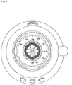
- FIG. 1 is a perspective view illustrating an appearance of a milk foamer according to an embodiment of the present invention.
- FIGS. 2A and 3 are cross sectional views of the milk foamer illustrated in FIG. 1 cut in the vertical direction.
- FIG. 2A is a view illustrating the milk foamer cut along a plane including a handle
- FIG. 3 is a view cut along a vertical plane orthogonal to the cut plane in FIG. 2A .
- the milk foamer is roughly composed of a base body 1, a cup body 2, and a cup lid 3.
- the base body 1 is composed of a lower base 10 and an upper base 11 coupled to the lower base 10.
- Three operation units (operation buttons) 11a, 11b, and 11c are provided on the upper base 11.
- Each of the operation units 11a, 11b, and 11c includes a switch mechanism therein.
- the lower base 10 and the upper base 11 are coupled to each other with an appropriate method such as a screw.
- the operation unit 11a is a button for turning on or off a power source.
- the operation unit 11b is a button for creating hot milk foamer.
- the operation unit 11c is a button for creating ice milk foamer.
- the operation unit 11b is a button for creating both foam milk and foamless hot milk.
- the lower base 10 is provided with three legs 10a on its bottom.
- the legs 10a are made of a material such as a rubber, and can be stably placed on a table or the like.
- the lower base 10 is also provided with a power source terminal for a power supply from a commercial power source on an appropriate position.
- the cup body 2 includes a beverage container 20, an upper cup support body 21 for supporting the beverage container 20, a lower cup support body 22, a bottom cup support body 23, and a handle 24 connected to the upper cup support body 21.
- a bottom 20a of the beverage container 20 of the cup body 2 is placed on a top surface 62a of a heater 62 provided on the base body 11.
- a user can detachably set the cup body 2 on the base body 1 by holding the handle 24.
- the beverage container 20 may be made of a metal such as aluminum or made of resin.
- the beverage container 20 may be made of a combination of stainless steel and aluminum.
- the beverage container 20 can be formed by using aluminum, having excellent thermal conductivity, for its bottom, and using stainless steel, which is easy to cut off heat, for its side face.
- the bonding portion of aluminum and stainless steel can be bonded by welding. With this configuration, when a user puts his/her mouth on the beverage container, he/she does not feel hot on the stainless steel part. Since the bottom is made of aluminum, heat is sufficiently transmitted to the milk in the beverage container, so that the milk can be heated quickly.
- a step is formed on the lower part of the upper cup support body 21, and the step is located just on an upper end face of the lower cup support body 22.
- the handle 24 is connected to the upper cup support body 21 with a screw 22a.
- two projections 20b are formed at the inside of the beverage container 20.
- Each of the projections 20b projects inward from the inner peripheral surface of the beverage container 20, and extends in the vertical direction.
- the lower part is located slightly above the stirring head 50, and the upper part is located near the boundary between the upper cup support body 21 and the lower cup support body 22.
- the formation of the projections 20b makes it easy to foam milk with the generation of a turbulent stirring state upon stirring milk. Milk can be largely foamed more with turbulent rotation.
- the bottom cup support body 23 is made of a material having flexibility such as a silicon rubber, and it can be placed onto a table or the like when the cup body 2 is removed from the base body 1. Since the bottom 20a (bottom surface) of the beverage container 20 is in a heated state, it is configured to prevent the user from carelessly touching the bottom 20a with his/her hand.
- the lower end of the bottom cup support body 23 projects from the bottom 20a of the beverage container 20 to make it difficult to be touched. This configuration also prevents the bottom 20a from being in direct contact with a table surface, when the cup body 2 is placed on a table or the like.
- the upper cup support body 21 and the lower cup support body 22 are provided to prevent a direct touch on the heated beverage container 20, and they are made of resin having low conduction of heat. Beverage (milk) stored in the cup body 2 can be transferred into a container containing another beverage such as coffee, or the cup body 2 can be used as a beverage cup.
- the cup lid 3 includes a lid body 30, a lid handle 31, and a packing 32.
- the cup lid 3 is provided with a first projecting cylindrical portion 30a projecting toward the beverage container 20 on the center of the lid body 30.
- the lid handle 31 is provided with an engagement claw 31a engaged with the first projecting cylindrical portion 30a, the lid handle 31 and the engagement claw 31a being integrally formed.
- a groove 30c is formed on the outer peripheral side surface of the lid body 30, and an annular packing 32 is inserted therein.
- the packing 32 is in close contact with the upper inner wall of the beverage container 20 to seal the beverage container 20, when the cup lid 3 is attached to the beverage container 20.
- the lid body 30 is preferably made of a transparent resin in order that it becomes easy to see the inside of the beverage container 20.
- a stirring mechanism 5 is provided on the bottom surface of the cup lid 3.
- the cup lid 3 and the stirring mechanism 5 are integrally formed as a unit. When the cup lid 3 is removed from the cup body 2, the stirring mechanism 5 is removed together.
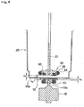
- the stirring mechanism 5 includes a stirring head 50 and a shaft 51.
- FIG. 2B is a view illustrating a cross-sectional structure of the stirring head 50 in detail.
- the stirring head 50 includes a lower first head composing member 52 and an upper second head composing member 53.
- a first concave part 52a with a cross-section of a quarter of a circle is formed on the outer periphery of the first head composing member 52, and a first concave part 53a with similarly a cross-section of a quarter of a circle is formed on the outer periphery of the second head composing member 53.
- the second head composing member 53 is made of a magnetic body.
- a semicircular recess is formed from the first concave part 52a and the second concave part 53a.
- a stirring blade 54 is inserted into this semicircular recess.
- the stirring blade 54 is formed into a coil spring shape, and includes a metallic wire 55 formed therein. The stirring blade 54 is fixed to the semicircular recess with this wire 55.
- FIG. 5 illustrates the stirring head 50 viewed from top.
- the second head composing member 53 has a cross shape, and the first concave part 53a is formed on a portion 53b projecting into a cross shape.
- a recess 53c is formed between the projecting portions 53b.
- FIG. 6 illustrates that four permanent magnets 60 are disposed with intervals of 90°, and these four permanent magnets 60 compose a first permanent magnet group 60A.
- a cylindrical projecting part 52c is formed at the center of the first head composing member 52.
- the second head composing member 53 is annularly formed, and its inner diameter part is fitted into the cylindrical projecting part 52c.
- connection member 56 includes a surface on which a screw is formed, and the connection member 56 connects the stirring head 50 and the shaft 51 to each other and fixes them. They can be connected to each other with the screw formed on the connection member 56 and a screw formed on the shaft 51.
- the shaft 51 is connected to a second projecting cylindrical part 30b, which is integrally formed with the lid body 30, via a bearing 33. With this structure, the shaft 51 and the stirring head 50 are supported so as to be relatively rotatable with respect to the lid body 30.
- a second permanent magnet group 61A is disposed on the base body 1 so as to be opposite to the first permanent magnet group 60A.
- the second permanent magnet group 61A is composed of four permanent magnets 61 disposed along the circumferential direction at an interval of 90°, like the first permanent magnet group 60A.
- the radius of rotation is the same as that of the first permanent magnet group 60A.
- the second permanent magnet group 61A is held on the back surface of a plate-type support member 16.
- a connection member 17 is provided at the center of the support member 16, and a motor shaft 15a of a motor 15 serving as an actuator is fitted into the connection member 17. With this configuration, when the motor 15 is driven, the support member 16 rotates to rotatably drive the second permanent magnet group 61A.
- FIG. 7 illustrates the arrangement of the first and second permanent magnet groups 60A and 61A in the vertical direction.
- the first permanent magnet group 60A is disposed such that the permanent magnet 60 whose south pole is directed downward and whose north pole is directed upward and the permanent magnet 60 whose north pole is directed upward and whose south pole is directed downward are alternately disposed along the circumferential direction.
- the second permanent magnet group 61A is disposed such that the permanent magnet 61 whose south pole is directed downward and whose north pole is directed upward and the permanent magnet 61 whose north pole is directed upward and whose south pole is directed downward are alternately disposed along the circumferential direction.
- the beverage container 20 is stably held with the state in which the north pole (south pole) of the first permanent magnet 60 faces the south pole (north pole) of the second permanent magnet 61.
- the first permanent magnet group 60A can be rotatably driven with the rotation of the second permanent magnet group 61A.
- the stirring head 50 rotates, whereby the milk in the beverage container 20 can be stirred.
- the permanent magnets can be disposed with high magnetic flux density.
- FIG. 8 illustrates a distance h1 between the stirring head 50 and the bottom surface 20a of the beverage container 20, a distance h2 between the first permanent magnet group 60A and the second permanent magnet group 61A, and a distance h3 between the second permanent magnet group 61A and the bottom surface 20a of the beverage container 20.
- a preferable range of h1 is 1 mm to 8 mm
- a preferable range of h2 is 3 mm to 15 mm
- a preferable range of h3 is 1 mm to 5 mm.
- a more preferable range of h1 is 1.5 mm to 2 mm
- a more preferable range h2 of h2 is 5.1 mm to 5.9 mm
- a more preferable range of h3 is 2 mm to 2.3 mm.
- a heater (heating device) 62 is provided to enclose the outer periphery of the second permanent magnet group 61A.
- the bottom surface 20a of the cup body 2 is placed onto a top surface 62a of the heater 62.
- FIG. 4 is a plan view illustrating the top surface 62a of the heater 62 viewed from top.
- a magnet cover 18 is provided above the second permanent magnet group 61A, and the magnet cover 18 and the top surface 62a of the heater 62 are flush with each other. Note that FIG. 4 illustrates the state in which the magnet cover 18 is removed.
- the stirring head 50 (first stirring head) has a shape suitable for creating foam milk.
- the milk foamer according to the present invention can create regular hot milk, in addition to foam milk, and for this, a stirring head with a different structure is used.
- the shaft 51 and the connection member 56 are connected to each other with a screw, so that the stirring head 50 can be replaced with another one.
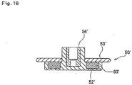
- FIG. 18 is a view illustrating a stirring head 50' (second stirring head) for hot milk.
- This stirring head is different from the one for foam milk in that it does not include the stirring blade 54.
- a connection member 56', a first head composing member 52', and a second head composing member 53' are basically the same.
- the number and arrangement of the permanent magnet 60' are the same as those for the first stirring head 50.
- a storage concave part 10b is formed on the lower base 10 of the base body 1.
- a frame member 13 made of a magnetic body such as stainless steel is provided at the opposite side (inside) on the bottom of the storage concave part 10b. Since the stirring head 50 includes the permanent magnets 60, the storage concave part 10b can hold the stirring head with the magnetic force.
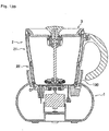
- FIG. 9 is a view illustrating a state in which the cup body 2 is removed from the base body 1.
- the top surface 62a of the heater 62 is exposed, and a careless touch with one's hand might cause a risk of burn injury.
- the heater cover 4 is provided.
- the heater cover 4 is rotatably and pivotally supported about a hinge shaft 4a.
- the hinge shaft 4a is provided on the upper base 11 of the base body 1.
- a restriction portion 4b is integrally formed with the heater cover 4, so that the heater cover 4 is stably supported with the state illustrated in FIG. 3 .
- FIG. 10 illustrates the covering state of the heater cover 4.
- the heater cover 4 is provided with a lot of small holes 4c. These holes are formed for heat release.
- Elastic members 4d are provided on three positions on the back surface of the heater cover 4. These members serve as a cushion upon the covering as illustrated in FIG. 10 .
- the elastic member 4 is made of a silicon rubber.
- a temperature sensor 70 and a cup detection sensor 71 are provided.
- the temperature sensor 70 is biased upward with a spring 72, and its tip end 70a can be in contact with the bottom surface 20a of the beverage container 20. Thus, the temperature of the milk in the beverage container 20 is detected.
- a tip end 71a of the cup detection sensor 71 is also biased upward with a spring, and this tip end 70a can be in contact with the bottom 20a of the beverage container 20. With this configuration, whether the cup body 2 (beverage container 20) is present or not can be detected, whereby the heater 62 is controlled not to be heated when the cup body 2 is absent.
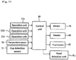
- FIG. 11 is a control block diagram.
- a control unit 80 performs a predetermined control according to a program preliminarily incorporated.
- the control unit 80 performs a control to the motor 15, the heater 62, and a thermostat 81 according to the operation inputs of the operation units 11a, 11b, and 11c and the detection results of the temperature sensor 70 and the cup detection sensor 71.
- the control unit 80 also performs a control for a head detection unit 82 to detect the presence of the stirring head 50.
- a head detection unit 82 to detect the presence of the stirring head 50.
- the load of the motor 15 becomes light. Whether the load is heavy or light can be detected from the current value of the motor 15 based on the function of the head detection unit 82.
- an alarm display e.g., a sound or lamp display
- the operation sequence is the same between the case of creating hot milk foam and the case of creating hot milk. In either case, the sequence is started by a pressing operation of the operation unit 11b. However, upon creating hot milk foam, the first stirring head 50 is used, and upon creating hot milk, the second stirring head 50' is used.
- the operation unit 11a is turned on to leave the power on, and then, an appropriate amount of milk is put in the beverage container 20. Then, the cup body 2 is placed onto the base body 1. Subsequently, the operation unit 11b is operated (t0). When the temperature is not more than a predetermined value (e.g., 30 °C) according to the temperature sensor 70, the heater 62 is heated.
- a predetermined value e.g. 30 °C
- This operation is illustrated in (A) in FIG. 12A .
- the thermostat is on-off controlled. It is set such that the temperature of the milk becomes appropriate (e.g., 62 °C) at the point of the time t6.
- the heater is stopped (time t7).
- the heater 62 is started to be heated after a time t4 (e.g., after 20 seconds). This sequence is illustrated in (B). After a lapse of time t6, the thermostat is on-off controlled. The control after the t6 is the same as (A).
- a detection sequence by the temperature sensor 70 is illustrated in (E). At a time t8, the detection operation is turned off.
- the operation of the motor 15 is illustrated in (F). After the operation of the operation unit 11b, the motor 15 is not kept on, but the motor 15 is temporarily turned off at a time t1 (e.g., 0.5 second), and then, turned on at a time t2 (e.g., 1.5 seconds). This is performed for allowing the stirring head 50 to surely follow the rotation of the motor 15 upon rotating the stirring head 50 with the magnetic force of the permanent magnets.
- a time t1 e.g., 0.5 second
- t2 e.g. 1.5 seconds
- the motor 15 Before the motor 15 starts to rotate, the north pole and the south pole of the first permanent magnet group 60A and the second permanent magnet group 61A do not always face each other. Therefore, the motor 15 is rotated for a short time at the beginning, and then, it keeps turned on. This can surely rotate the stirring head 50.
- the motor 15 is turned off at a time t8. However, it is not suddenly turned off.
- the motor 15 is temporarily driven with power of 20 % to 80 % at the time t7, and then, turned off. This softens impact upon stopping the motor.
- the operation of the cup detection sensor 71 is illustrated in (G). To heat the heater 62 and rotate the motor 15, it is necessary that the cup body 2 is detected by the cup detection sensor 71. In the state in which the cup body 2 is not placed on the base body 1, the motor 15 is not rotated, and the heater 62 is not heated.
- the detection operation by the head detection unit 82 is started at the time t4 and ends at the time t7. This is for detecting whether the stirring head 50 is mounted or not.
- the start of the detection is set after a time t3 at which the continuous rotation of the motor 15 is started.
- the stirring head 50 When the stirring head 50 is not mounted, the load becomes light, so that the value of the current flowing through the motor 15 becomes not more than a predetermined value. When the stirring head 50 is not mounted, foam milk cannot be created. In view of this, the presence of the stirring head 50 is to be detected.
- a sequence of creating ice milk foam will next be described with reference to FIG. 12B .
- a control upon start-up of the motor 15 is illustrated in (K). This is the same as FIG. 12A .
- the operation of the cup detection sensor 71 is illustrated in (L). This is also basically the same as FIG. 12A .
- a sequence (M) of the head detection is also the same as FIG. 12A .
- the operation unit 11c is operated, and the heater 62 is on-off controlled after a lapse of the time t4 (e.g., 30 seconds).
- a lapse of the time t4 e.g. 30 seconds.
- This sequence is illustrated in (I).
- the heater 62 is turned on. Thereafter, 3 seconds on and 7 seconds off (pulse drive) are repeated until a time t5.
- the heater 62 is not heated.
- FIG. 19 is a view illustrating another embodiment of the cup body 2.
- a beak part 25 (guide part) is provided to facilitate pouring of milk into another container.
- the beak part 25 can be formed integrally with the beverage container 20 or the upper cup support body 21.
- only the beak part 25 can be formed as a separate member, and attached to a beverage container 20 or an upper cup support body 21 having no beak part. With this configuration, pouring of milk can be facilitated with a cup body 2 having no beak part.
- a configuration of a cover at the lower part of the cup body 2 will be described. After the milk has been heated, the bottom 20a of the beverage container 20 of the cup body 2 becomes hot. Therefore, a careless touch with one's hand has to be inhibited. In view of this, a cover member is provided at the lower part of the cup body 2.
- FIG. 13 illustrates a configuration of a cover according to the first embodiment.
- FIG. 13A is a view illustrating a state in which the cup body 2 is removed from the base body 1.
- a cover member 100 is formed to be movable in the vertical direction on the outer peripheral surface of the lower cup support body 22 composing the cup body 2.
- the cover member 100 moves down with its own weight. Therefore, the bottom 20a of the beverage container 20 is difficult to be touched.
- FIG. 14 illustrates a configuration of a cover according to a second embodiment.
- a cover member 110 includes a ring part 110a, a bottom lid part 110b, and a connection part 110c connecting the ring part 110a and the bottom lid part 110b to each other, the ring part 110a, the bottom lid part 110b, and the connection part 110c being formed integrally with one another.
- the cover member 110 is made of a soft material such as silicon. Since the bottom lid part 110b is provided, the bottom 20a of the beverage container 20 is completely covered.
- the ring part 110a of the cover member 110 can be configured to be fixed on the peripheral surface of the lower cup support body 22.
- the cover member 110 has flexibility. Therefore, when the cup body 2 is placed on the base body 1, the bottom lid part 110b can be placed out of the way by bending the connection part 110c. In addition, since the ring part 110a is fixed to the lower cup support body 22, there is no risk of loss of the cover member 110.
- FIG. 14A is a view illustrating a state in which the cup body 2 is removed. If the bottom lid part 110b is covered on the bottom 20a of the beverage container 20, the cup body 2 can be directly placed onto a table or the like without being directly touched on its bottom with one's hand.
- FIG. 15 illustrates a configuration of a cover according to a third embodiment.
- a cover member 120 includes a bottom lid part 120a, a fixing part 120b, and a communication part 120c connecting the bottom lid part 120a and the fixing part 120b to each other, the bottom lid part 120a, the fixing part 120b, and the communication part 120c being formed integrally with one another.
- the cover member 120 is made of a soft material such as silicon. Since the bottom lid part 120a is provided, the bottom 20a of the beverage container 20 is completely covered.
- the fixing part 120b is fixed on the outer surface of the lower cup support body 22 of the cup body 2.
- the fixing part 120b can be fixed with any appropriate methods using a screw or with bonding.
- the cover member 120 has flexibility.
- the bottom lid part 120a can be placed out of the way by bending the connection part 120c.
- the fixing part 120b is fixed to the lower cup support body 22, there is no risk of loss of the cover member 120.
- FIG. 15A is a view illustrating a state in which the cup body 2 is removed. If the bottom lid part 120a is covered on the bottom 20a of the beverage container 20, the cup body 2 can be directly placed onto a table or the like without being directly touched on its bottom with one's hand.
- FIG. 16 illustrates a configuration of a cover according to a fourth embodiment.
- a cover member 130 includes a bottom lid part 130a, a ring part 130b, a communication part 130c connecting the bottom lid part 130a and the ring part 130b to each other, and a handle part 130d, the bottom lid part 130a, the ring part 130b, the communication part 130c, and the handle part 130d being formed integrally with one another.
- This cover member 130 is a member separate from the cup body 2. When the cup body 2 is removed from the base body 1, the cup body 2 is inserted from the ring part 130b of the cover member 130 as illustrated in FIG. 16A .
- the bottom lid part 130a is provided, the bottom 20a of the beverage container 20 is completely covered.
- the cup body 2 can be placed onto a table or the like with the cover member 130 being attached thereto.
- FIG. 17 illustrates a configuration of a cover according to a fifth embodiment.
- a cover member 140 includes a bottom lid part 140a and a hinge part 140b.
- the hinge part 140b is connected to the lower cup support body 22 of the cup body 2.
- a locking part 140c is integrally provided on the bottom lid part 140a at the side opposite to the hinge part 140b.
- the locking part 140b is locked to a locked part 22b formed on the outer surface of the lower cup support body 22 as illustrated in FIG. 17A .
- the locking state may be canceled.
- Locking or releasing the locking part 140b can easily be performed by forming the locking part 140b from resin having flexibility.
- the number of the permanent magnets disposed along the circumferential direction is four. However, it is not limited thereto. Two or three, or five or more permanent magnets can be disposed.
- the cover member 130 can be integrally formed with resin molding.
- a surface made of silicon is formed on the bottom surface of the bottom lid part 130a on which the beverage container 20 of the cup body 2 is placed.
- the stirring head is rotated with the combination of the first permanent magnet group and the second permanent magnet group.
- the permanent magnet group may be composed of an electromagnet.
- an electromagnet coil can be applied instead of the second permanent magnet group 61A as a magnetic drive mechanism.
- the present embodiment describes that the shaft 51 and the stirring head 50 are supported so as to be relatively rotatable with respect to the lid body 30.
- the lid body 30 and the shaft 51 are connected to each other so as not to relatively rotate, and the stirring head 50 can be connected to the shaft 51 so as to be relatively rotatable.
- the stirring blade 54 has a coil shape.
- the shape of the blade is not limited to a specific shape.
- the milk foamer according to the present embodiment has a function of creating both foam milk and hot milk.
- the milk foamer can be configured to have a function of creating only foam milk, or a function of creating another type of beverage.
- detection by the head detection unit 82 is performed with a current detection.
- a sensor such as an optical sensor or a mechanical sensor.
Claims (11)
- Mousseur à lait comprenant :- un corps de base (1) ;- un corps formant coupe (2) placé sur le corps de base (1) ;- un couvercle de coupe (3) placé sur le corps formant coupe (2) ; et- un mécanisme de brasage (5) configuré pour brasser du lait dans le corps formant coupe (2),dans lequel le mécanisme de brassage (5) inclut une tête de brassage (50) et une tige (51) pour supporter la tête de brassage (50), et
dans lequel un mécanisme d'entraînement magnétique configuré pour entraîner la tête de brassage (50) par voie magnétique est prévu sur le corps de base (1),
caractérisé en ce que
le mousseur à lait comprend en outre une unité de détection de tête (82) qui détecte pour savoir si la tête de brassage (50) est attachée sur la tige (51) ou non. - Mousseur à lait selon la revendication 1,
dans lequel la tête de brassage (50) inclut un premier groupe d'aimants permanents (60A) disposés à intervalles égaux le long d'une direction circonférentielle de rotation. - Mousseur à lait selon la revendication 2,
dans lequel le mécanisme d'entraînement magnétique inclut un second groupe d'aimants permanents (61A) disposés à l'opposé du premier groupe d'aimants permanents (60A), et un actionneur (15) pour mettre en rotation le second groupe d'aimants permanents (61A). - Mousseur à lait selon la revendication 2 ou 3,
dans lequel la tête de brassage (50) inclut une pale de brassage (54) prévue autour du premier groupe d'aimants permanents (60A). - Mousseur à lait selon la revendication 4,
dans lequel la pale de brassage (54) est montée sur une surface de support formée sur un élément de support (16A) qui supporte le premier groupe d'aimants permanents (60A). - Mousseur à lait selon l'une quelconque des revendications 1 à 5,
dans lequel un ou plusieurs types de pales de brassage (50, 50') sont préparés, et sont attachés sur la tige (51) de manière à être interchangeables. - Mousseur à lait selon la revendication 6,
dans lequel une partie de stockage (10b) pour stocker la tête de brassage (50) est prévue sur le corps de base (1). - Mousseur à lait selon la revendication 7,
dans lequel la partie de stockage (10b) est une partie de stockage concave formée sur un fond du corps de base (1) pour retenir la tête de brassage (50) avec une force magnétique. - Mousseur à lait selon la revendication 3,
dans lequel un dispositif de chauffage (62) est prévu pour entourer le second groupe d'aimants permanents (61A). - Mousseur à lait selon l'une quelconque des revendications 1 à 9,
dans lequel un capteur (71) pour détecter la présence du corps formant coupe (2) est prévu sur le corps de base (1). - Mousseur à lait selon la revendication 9,
dans lequel un couvercle de chauffage (4) qui couvre la surface de chauffage du dispositif de chauffage (62) est supporté en rotation et en pivotement sur le corps de base (1).
Applications Claiming Priority (9)
| Application Number | Priority Date | Filing Date | Title |
|---|---|---|---|
| CN2013100727011A CN103169374A (zh) | 2013-03-07 | 2013-03-07 | 奶泡机 |
| CN 201320103994 CN203168874U (zh) | 2013-03-07 | 2013-03-07 | 一种奶泡机 |
| CN 201320104108 CN203168875U (zh) | 2013-03-07 | 2013-03-07 | 一种奶泡机 |
| CN 201320104219 CN203168876U (zh) | 2013-03-07 | 2013-03-07 | 一种奶泡机 |
| CN 201320113314 CN203234564U (zh) | 2013-03-13 | 2013-03-13 | 一种侧式电机的奶泡机 |
| CN201320330547.9U CN203388695U (zh) | 2013-06-08 | 2013-06-08 | 一种底部驱动式奶泡机 |
| CN201320431680.3U CN203447144U (zh) | 2013-07-19 | 2013-07-19 | 一种电磁驱动式奶泡机 |
| CN2013103049655A CN103417113A (zh) | 2013-07-19 | 2013-07-19 | 一种电磁驱动式奶泡机 |
| PCT/JP2014/055621 WO2014136833A1 (fr) | 2013-03-07 | 2014-03-05 | Mousseur à lait |
Publications (3)
| Publication Number | Publication Date |
|---|---|
| EP2965670A1 EP2965670A1 (fr) | 2016-01-13 |
| EP2965670A4 EP2965670A4 (fr) | 2017-03-01 |
| EP2965670B1 true EP2965670B1 (fr) | 2019-09-11 |
Family
ID=51491342
Family Applications (1)
| Application Number | Title | Priority Date | Filing Date |
|---|---|---|---|
| EP14761055.4A Active EP2965670B1 (fr) | 2013-03-07 | 2014-03-05 | Mousseur à lait |
Country Status (8)
| Country | Link |
|---|---|
| US (1) | US9751054B2 (fr) |
| EP (1) | EP2965670B1 (fr) |
| JP (1) | JP5774791B2 (fr) |
| KR (1) | KR101764523B1 (fr) |
| CA (1) | CA2902410C (fr) |
| SG (1) | SG11201506710SA (fr) |
| TW (1) | TWI621417B (fr) |
| WO (1) | WO2014136833A1 (fr) |
Families Citing this family (30)
| Publication number | Priority date | Publication date | Assignee | Title |
|---|---|---|---|---|
| US11730293B2 (en) * | 2010-10-29 | 2023-08-22 | Mpd Ventures, Inc. | Drink lid arrangements and methods |
| US10244772B2 (en) * | 2014-11-06 | 2019-04-02 | Sagra, Inc. | Method for creating layered chocolate body and chocolate mold for creation thereof |
| CN107613817B (zh) * | 2015-03-30 | 2021-05-07 | 布瑞威利私人有限公司 | 使奶起泡的改进装置和方法 |
| JP6068709B2 (ja) * | 2015-05-18 | 2017-01-25 | シャープ株式会社 | 撹拌子および撹拌装置 |
| RU2019101381A (ru) * | 2016-06-22 | 2020-07-22 | Сосьете Де Продюи Нестле С.А. | Устройство поточного нагрева |
| PT3554324T (pt) * | 2016-12-13 | 2021-07-14 | Nestle Sa | Batedor ergonómico para processamento de alimentos |
| JP7245159B2 (ja) * | 2016-12-13 | 2023-03-23 | ソシエテ・デ・プロデュイ・ネスレ・エス・アー | 泡立て器のための磁気的な高トルク伝達 |
| US10441113B2 (en) * | 2017-10-03 | 2019-10-15 | Hamilton Beach Brands, Inc. | Blender jar lid with tortuous airflow path |
| DE102017128820A1 (de) * | 2017-12-05 | 2019-06-06 | Vorwerk & Co. Interholding Gmbh | Betätigungseinrichtung mit Magneten |
| CN107928464B (zh) * | 2017-12-25 | 2024-04-09 | 唐锋机电科技(深圳)有限公司 | 杯座、搅拌杯以及台式搅拌机 |
| EP3530160B1 (fr) * | 2018-02-21 | 2020-08-05 | Vorwerk & Co. Interholding GmbH | Dispositif de préparation d'aliments comprenant un verrouillage |
| BR112020017335A2 (pt) | 2018-03-29 | 2020-12-15 | Société des Produits Nestlé S.A. | Posicionamento controlado em processador de alimentos |
| CN110393461A (zh) * | 2018-04-24 | 2019-11-01 | 主力智业(深圳)电器实业有限公司 | 一种磁驱静音搅拌机 |
| FR3080526B1 (fr) * | 2018-04-30 | 2020-04-03 | Beaba | Dispositif de chauffage de liquide alimentaire, par exemple de boisson lactee |
| US10350561B1 (en) | 2018-08-03 | 2019-07-16 | Boris Dushine | Magnetic stirring system for wine aeration and method of using same |
| US10220361B1 (en) | 2018-08-03 | 2019-03-05 | Boris Dushine | Magnetic stirring system for the automated and optimized reconstitution of powdered infant formulations and methods of using same |
| US20200113369A1 (en) * | 2018-10-16 | 2020-04-16 | Team International Group of America Inc. | Coffee maker and frother |
| CN109497852B (zh) * | 2018-11-29 | 2021-08-03 | 九阳股份有限公司 | 一种食品加工机的控制方法 |
| KR102171689B1 (ko) * | 2019-04-09 | 2020-10-30 | 주식회사 캠프런 | 음료 제조 장치 및 시스템 |
| KR102482005B1 (ko) * | 2020-09-15 | 2022-12-27 | 씰링크 주식회사 | 밀봉기능이 향상된 교반기 및 이에 사용되는 씰링유닛 |
| JP7411597B2 (ja) | 2021-03-08 | 2024-01-11 | 日立グローバルライフソリューションズ株式会社 | 飲料製造装置 |
| US11647860B1 (en) | 2022-05-13 | 2023-05-16 | Sharkninja Operating Llc | Flavored beverage carbonation system |
| US11751585B1 (en) | 2022-05-13 | 2023-09-12 | Sharkninja Operating Llc | Flavored beverage carbonation system |
| WO2023216231A1 (fr) | 2022-05-13 | 2023-11-16 | Sharkninja Operating Llc | Agitateur pour système de carbonatation |
| US11738988B1 (en) | 2022-11-17 | 2023-08-29 | Sharkninja Operating Llc | Ingredient container valve control |
| US11745996B1 (en) | 2022-11-17 | 2023-09-05 | Sharkninja Operating Llc | Ingredient containers for use with beverage dispensers |
| US11634314B1 (en) | 2022-11-17 | 2023-04-25 | Sharkninja Operating Llc | Dosing accuracy |
| US11925287B1 (en) | 2023-03-22 | 2024-03-12 | Sharkninja Operating Llc | Additive container with inlet tube |
| US11871867B1 (en) | 2023-03-22 | 2024-01-16 | Sharkninja Operating Llc | Additive container with bottom cover |
| US11931704B1 (en) | 2023-06-16 | 2024-03-19 | Sharkninja Operating Llc | Carbonation chamber |
Family Cites Families (27)
| Publication number | Priority date | Publication date | Assignee | Title |
|---|---|---|---|---|
| JPS5528359U (fr) * | 1978-08-16 | 1980-02-23 | ||
| JPS5528359A (en) | 1978-08-22 | 1980-02-28 | Nippon Mining Co Ltd | High carbon ferronickel shotting method |
| JPH0328917Y2 (fr) | 1985-10-15 | 1991-06-20 | ||
| JPH0522254Y2 (fr) | 1986-04-08 | 1993-06-08 | ||
| JPH01243390A (ja) | 1988-03-25 | 1989-09-28 | Toshiba Corp | 電磁調理装置付き電子レンジ |
| JPH054889U (ja) * | 1991-07-12 | 1993-01-26 | キーパーインターナシヨナル株式会社 | 発酵乳調製品の製造装置 |
| JPH0722144Y2 (ja) | 1992-07-29 | 1995-05-24 | 幸雄 児玉 | 2重筒コップ |
| JPH07136072A (ja) * | 1993-11-16 | 1995-05-30 | Hitachi Home Tec Ltd | 調理用撹拌機 |
| JPH08332398A (ja) | 1995-06-07 | 1996-12-17 | Teizo Sato | 穀物の磨ぎ洗い機 |
| JPH11221160A (ja) * | 1998-02-10 | 1999-08-17 | Takata Kk | 保温器 |
| BR0017283A (pt) | 2000-06-22 | 2004-02-25 | Arno Sa | Aparelho para processamento de alimentos com suporte para ferramentas armazenáveis |
| JP2002204936A (ja) * | 2001-01-10 | 2002-07-23 | Ms Engineering:Kk | 磁石を用いた攪拌機軸カップリング及び攪拌槽 |
| AU2002316157A1 (en) * | 2001-05-22 | 2002-12-09 | Shurflo Pump Manufacturing Company, Inc. | Appliance and an appliance drive unit |
| JP3091839U (ja) * | 2002-08-01 | 2003-02-21 | 重亮 高木 | 調理用電動撹拌機 |
| JP2005269709A (ja) | 2004-03-16 | 2005-09-29 | Maguneo Giken:Kk | 磁気回転伝達装置及び密閉撹拌装置 |
| EP1656866A1 (fr) * | 2004-11-12 | 2006-05-17 | Nestec S.A. | Appareil et méthode pour la préparation de mousse à partir d'un liquide alimentaire à base de lait |
| PT2174576E (pt) | 2007-05-23 | 2013-11-11 | Nestec Sa | Aparelho para condicionamento de um líquido à base de leite |
| DE102007063549A1 (de) | 2007-12-21 | 2009-06-25 | Eldora Gmbh | Automatischer Milchschaumbereiter |
| WO2009097705A1 (fr) * | 2008-02-08 | 2009-08-13 | Domo Vision Ag | Appareil pour mélanger, faire mousser et éventuellement chauffer des aliments liquides |
| FR2930882B1 (fr) * | 2008-05-07 | 2010-05-07 | Cie Mediterraneenne Des Cafes | Mousseur pour preparer de la mousse a partir d'une boisson comprenant du lait |
| JP5359084B2 (ja) | 2008-07-23 | 2013-12-04 | パナソニック株式会社 | 電動調理器 |
| US8087603B2 (en) | 2008-08-15 | 2012-01-03 | Vita-Mix Corporation | Sealing enclosure for a blender |
| JP2011156200A (ja) | 2010-02-02 | 2011-08-18 | Sharp Corp | 電気炊飯器 |
| ES2383985B1 (es) * | 2010-03-16 | 2013-05-07 | Electrodomésticos Taurus S.L. | Recipiente de cocina con cuchillas giratorias. |
| US20130081545A1 (en) * | 2010-06-11 | 2013-04-04 | Breville Pty Limited | Milk Frother |
| WO2012076848A1 (fr) | 2010-12-07 | 2012-06-14 | Alex Gort-Barten | Pot à mousser le lait |
| CN202723654U (zh) * | 2012-09-12 | 2013-02-13 | 陈玉水 | 具有新型搅拌装置的液体食品发泡机 |
-
2014
- 2014-03-05 WO PCT/JP2014/055621 patent/WO2014136833A1/fr active Application Filing
- 2014-03-05 US US14/772,362 patent/US9751054B2/en active Active
- 2014-03-05 KR KR1020157027775A patent/KR101764523B1/ko active IP Right Grant
- 2014-03-05 EP EP14761055.4A patent/EP2965670B1/fr active Active
- 2014-03-05 JP JP2014537414A patent/JP5774791B2/ja active Active
- 2014-03-05 CA CA2902410A patent/CA2902410C/fr active Active
- 2014-03-05 SG SG11201506710SA patent/SG11201506710SA/en unknown
- 2014-03-07 TW TW103107963A patent/TWI621417B/zh active
Non-Patent Citations (1)
| Title |
|---|
| None * |
Also Published As
| Publication number | Publication date |
|---|---|
| EP2965670A1 (fr) | 2016-01-13 |
| JP5774791B2 (ja) | 2015-09-09 |
| WO2014136833A1 (fr) | 2014-09-12 |
| US9751054B2 (en) | 2017-09-05 |
| TW201509353A (zh) | 2015-03-16 |
| KR101764523B1 (ko) | 2017-08-03 |
| CA2902410C (fr) | 2017-07-18 |
| EP2965670A4 (fr) | 2017-03-01 |
| SG11201506710SA (en) | 2015-09-29 |
| KR20160005684A (ko) | 2016-01-15 |
| JPWO2014136833A1 (ja) | 2017-02-16 |
| CA2902410A1 (fr) | 2014-09-12 |
| US20160030900A1 (en) | 2016-02-04 |
| TWI621417B (zh) | 2018-04-21 |
Similar Documents
| Publication | Publication Date | Title |
|---|---|---|
| EP2965670B1 (fr) | Mousseur à lait | |
| JP2021516565A (ja) | 食品プロセッサの取り扱い | |
| CN202981697U (zh) | 一个用于搅拌液体食物或饮料的可拆卸式装置 | |
| JP2015521938A (ja) | 液体食料品を攪拌するための装置 | |
| US20190335952A1 (en) | Apparatus for preparing a foam from a liquid, particularly a food liquid, such as milk or a milk-based liquid | |
| JP7196260B2 (ja) | 加熱調理システム | |
| JP2021517016A (ja) | 食品プロセッサ内での制御された位置決め | |
| EP2882320B1 (fr) | Dispositif pour faire mousser le lait | |
| JPWO2019069497A1 (ja) | 加熱調理装置 | |
| JP3178503U (ja) | 加熱機能付きタンブラー | |
| JP2000041838A (ja) | 電気鍋 | |
| GB2495218A (en) | Food processor with magnetic tool and bowl | |
| CN105873479A (zh) | 奶泡器 | |
| JP2011156023A (ja) | 電気炊飯器 | |
| US20120186462A1 (en) | Device for foaming milk | |
| JP2012125467A (ja) | 炊飯器 | |
| JP7446106B2 (ja) | 加熱調理器および加熱調理システム | |
| KR20150006699A (ko) | 유아용 이유식 용기 | |
| JP2012040404A (ja) | 調理器 | |
| CN112842103A (zh) | 烹饪装置 | |
| JP2000139694A (ja) | 炊飯器 | |
| CN217659425U (zh) | 食品搅拌杯及食品料理机 | |
| JP2021517012A (ja) | 食品プロセッサの熱管理 | |
| CN211862543U (zh) | 奶泡机 | |
| CN211511436U (zh) | 烹饪器具 |
Legal Events
| Date | Code | Title | Description |
|---|---|---|---|
| PUAI | Public reference made under article 153(3) epc to a published international application that has entered the european phase |
Free format text: ORIGINAL CODE: 0009012 |
|
| 17P | Request for examination filed |
Effective date: 20151005 |
|
| AK | Designated contracting states |
Kind code of ref document: A1 Designated state(s): AL AT BE BG CH CY CZ DE DK EE ES FI FR GB GR HR HU IE IS IT LI LT LU LV MC MK MT NL NO PL PT RO RS SE SI SK SM TR |
|
| AX | Request for extension of the european patent |
Extension state: BA ME |
|
| RAP1 | Party data changed (applicant data changed or rights of an application transferred) |
Owner name: UCC UESHIMA COFFEE CO., LTD. |
|
| DAX | Request for extension of the european patent (deleted) | ||
| RIC1 | Information provided on ipc code assigned before grant |
Ipc: B01F 3/04 20060101ALI20160928BHEP Ipc: A47J 31/44 20060101AFI20160928BHEP Ipc: A47J 43/046 20060101ALI20160928BHEP |
|
| A4 | Supplementary search report drawn up and despatched |
Effective date: 20170130 |
|
| RIC1 | Information provided on ipc code assigned before grant |
Ipc: A47J 31/44 20060101AFI20170124BHEP Ipc: A47J 43/046 20060101ALI20170124BHEP Ipc: B01F 3/04 20060101ALI20170124BHEP |
|
| GRAP | Despatch of communication of intention to grant a patent |
Free format text: ORIGINAL CODE: EPIDOSNIGR1 |
|
| STAA | Information on the status of an ep patent application or granted ep patent |
Free format text: STATUS: GRANT OF PATENT IS INTENDED |
|
| INTG | Intention to grant announced |
Effective date: 20190311 |
|
| GRAS | Grant fee paid |
Free format text: ORIGINAL CODE: EPIDOSNIGR3 |
|
| GRAJ | Information related to disapproval of communication of intention to grant by the applicant or resumption of examination proceedings by the epo deleted |
Free format text: ORIGINAL CODE: EPIDOSDIGR1 |
|
| GRAL | Information related to payment of fee for publishing/printing deleted |
Free format text: ORIGINAL CODE: EPIDOSDIGR3 |
|
| STAA | Information on the status of an ep patent application or granted ep patent |
Free format text: STATUS: REQUEST FOR EXAMINATION WAS MADE |
|
| GRAR | Information related to intention to grant a patent recorded |
Free format text: ORIGINAL CODE: EPIDOSNIGR71 |
|
| STAA | Information on the status of an ep patent application or granted ep patent |
Free format text: STATUS: GRANT OF PATENT IS INTENDED |
|
| GRAA | (expected) grant |
Free format text: ORIGINAL CODE: 0009210 |
|
| STAA | Information on the status of an ep patent application or granted ep patent |
Free format text: STATUS: THE PATENT HAS BEEN GRANTED |
|
| REG | Reference to a national code |
Ref country code: DE Ref legal event code: R082 Ref document number: 602014053474 Country of ref document: DE Representative=s name: MEISSNER BOLTE PATENTANWAELTE RECHTSANWAELTE P, DE |
|
| INTC | Intention to grant announced (deleted) | ||
| AK | Designated contracting states |
Kind code of ref document: B1 Designated state(s): AL AT BE BG CH CY CZ DE DK EE ES FI FR GB GR HR HU IE IS IT LI LT LU LV MC MK MT NL NO PL PT RO RS SE SI SK SM TR |
|
| INTG | Intention to grant announced |
Effective date: 20190806 |
|
| REG | Reference to a national code |
Ref country code: GB Ref legal event code: FG4D |
|
| REG | Reference to a national code |
Ref country code: CH Ref legal event code: EP |
|
| REG | Reference to a national code |
Ref country code: AT Ref legal event code: REF Ref document number: 1177384 Country of ref document: AT Kind code of ref document: T Effective date: 20190915 |
|
| REG | Reference to a national code |
Ref country code: DE Ref legal event code: R096 Ref document number: 602014053474 Country of ref document: DE Ref country code: IE Ref legal event code: FG4D |
|
| REG | Reference to a national code |
Ref country code: CH Ref legal event code: NV Representative=s name: WAGNER + HELBIG PATENTANWAELTE CONSEILS EN PRO, CH |
|
| REG | Reference to a national code |
Ref country code: NL Ref legal event code: FP |
|
| REG | Reference to a national code |
Ref country code: LT Ref legal event code: MG4D |
|
| PG25 | Lapsed in a contracting state [announced via postgrant information from national office to epo] |
Ref country code: FI Free format text: LAPSE BECAUSE OF FAILURE TO SUBMIT A TRANSLATION OF THE DESCRIPTION OR TO PAY THE FEE WITHIN THE PRESCRIBED TIME-LIMIT Effective date: 20190911 Ref country code: LT Free format text: LAPSE BECAUSE OF FAILURE TO SUBMIT A TRANSLATION OF THE DESCRIPTION OR TO PAY THE FEE WITHIN THE PRESCRIBED TIME-LIMIT Effective date: 20190911 Ref country code: BG Free format text: LAPSE BECAUSE OF FAILURE TO SUBMIT A TRANSLATION OF THE DESCRIPTION OR TO PAY THE FEE WITHIN THE PRESCRIBED TIME-LIMIT Effective date: 20191211 Ref country code: NO Free format text: LAPSE BECAUSE OF FAILURE TO SUBMIT A TRANSLATION OF THE DESCRIPTION OR TO PAY THE FEE WITHIN THE PRESCRIBED TIME-LIMIT Effective date: 20191211 Ref country code: HR Free format text: LAPSE BECAUSE OF FAILURE TO SUBMIT A TRANSLATION OF THE DESCRIPTION OR TO PAY THE FEE WITHIN THE PRESCRIBED TIME-LIMIT Effective date: 20190911 Ref country code: SE Free format text: LAPSE BECAUSE OF FAILURE TO SUBMIT A TRANSLATION OF THE DESCRIPTION OR TO PAY THE FEE WITHIN THE PRESCRIBED TIME-LIMIT Effective date: 20190911 |
|
| PG25 | Lapsed in a contracting state [announced via postgrant information from national office to epo] |
Ref country code: GR Free format text: LAPSE BECAUSE OF FAILURE TO SUBMIT A TRANSLATION OF THE DESCRIPTION OR TO PAY THE FEE WITHIN THE PRESCRIBED TIME-LIMIT Effective date: 20191212 Ref country code: RS Free format text: LAPSE BECAUSE OF FAILURE TO SUBMIT A TRANSLATION OF THE DESCRIPTION OR TO PAY THE FEE WITHIN THE PRESCRIBED TIME-LIMIT Effective date: 20190911 Ref country code: ES Free format text: LAPSE BECAUSE OF FAILURE TO SUBMIT A TRANSLATION OF THE DESCRIPTION OR TO PAY THE FEE WITHIN THE PRESCRIBED TIME-LIMIT Effective date: 20190911 Ref country code: AL Free format text: LAPSE BECAUSE OF FAILURE TO SUBMIT A TRANSLATION OF THE DESCRIPTION OR TO PAY THE FEE WITHIN THE PRESCRIBED TIME-LIMIT Effective date: 20190911 Ref country code: LV Free format text: LAPSE BECAUSE OF FAILURE TO SUBMIT A TRANSLATION OF THE DESCRIPTION OR TO PAY THE FEE WITHIN THE PRESCRIBED TIME-LIMIT Effective date: 20190911 |
|
| REG | Reference to a national code |
Ref country code: AT Ref legal event code: MK05 Ref document number: 1177384 Country of ref document: AT Kind code of ref document: T Effective date: 20190911 |
|
| PG25 | Lapsed in a contracting state [announced via postgrant information from national office to epo] |
Ref country code: EE Free format text: LAPSE BECAUSE OF FAILURE TO SUBMIT A TRANSLATION OF THE DESCRIPTION OR TO PAY THE FEE WITHIN THE PRESCRIBED TIME-LIMIT Effective date: 20190911 Ref country code: PL Free format text: LAPSE BECAUSE OF FAILURE TO SUBMIT A TRANSLATION OF THE DESCRIPTION OR TO PAY THE FEE WITHIN THE PRESCRIBED TIME-LIMIT Effective date: 20190911 Ref country code: AT Free format text: LAPSE BECAUSE OF FAILURE TO SUBMIT A TRANSLATION OF THE DESCRIPTION OR TO PAY THE FEE WITHIN THE PRESCRIBED TIME-LIMIT Effective date: 20190911 Ref country code: IT Free format text: LAPSE BECAUSE OF FAILURE TO SUBMIT A TRANSLATION OF THE DESCRIPTION OR TO PAY THE FEE WITHIN THE PRESCRIBED TIME-LIMIT Effective date: 20190911 Ref country code: RO Free format text: LAPSE BECAUSE OF FAILURE TO SUBMIT A TRANSLATION OF THE DESCRIPTION OR TO PAY THE FEE WITHIN THE PRESCRIBED TIME-LIMIT Effective date: 20190911 Ref country code: PT Free format text: LAPSE BECAUSE OF FAILURE TO SUBMIT A TRANSLATION OF THE DESCRIPTION OR TO PAY THE FEE WITHIN THE PRESCRIBED TIME-LIMIT Effective date: 20200113 |
|
| PG25 | Lapsed in a contracting state [announced via postgrant information from national office to epo] |
Ref country code: SK Free format text: LAPSE BECAUSE OF FAILURE TO SUBMIT A TRANSLATION OF THE DESCRIPTION OR TO PAY THE FEE WITHIN THE PRESCRIBED TIME-LIMIT Effective date: 20190911 Ref country code: IS Free format text: LAPSE BECAUSE OF FAILURE TO SUBMIT A TRANSLATION OF THE DESCRIPTION OR TO PAY THE FEE WITHIN THE PRESCRIBED TIME-LIMIT Effective date: 20200224 Ref country code: CZ Free format text: LAPSE BECAUSE OF FAILURE TO SUBMIT A TRANSLATION OF THE DESCRIPTION OR TO PAY THE FEE WITHIN THE PRESCRIBED TIME-LIMIT Effective date: 20190911 Ref country code: SM Free format text: LAPSE BECAUSE OF FAILURE TO SUBMIT A TRANSLATION OF THE DESCRIPTION OR TO PAY THE FEE WITHIN THE PRESCRIBED TIME-LIMIT Effective date: 20190911 |
|
| REG | Reference to a national code |
Ref country code: DE Ref legal event code: R097 Ref document number: 602014053474 Country of ref document: DE |
|
| PLBE | No opposition filed within time limit |
Free format text: ORIGINAL CODE: 0009261 |
|
| STAA | Information on the status of an ep patent application or granted ep patent |
Free format text: STATUS: NO OPPOSITION FILED WITHIN TIME LIMIT |
|
| PG2D | Information on lapse in contracting state deleted |
Ref country code: IS |
|
| PG25 | Lapsed in a contracting state [announced via postgrant information from national office to epo] |
Ref country code: DK Free format text: LAPSE BECAUSE OF FAILURE TO SUBMIT A TRANSLATION OF THE DESCRIPTION OR TO PAY THE FEE WITHIN THE PRESCRIBED TIME-LIMIT Effective date: 20190911 Ref country code: IS Free format text: LAPSE BECAUSE OF FAILURE TO SUBMIT A TRANSLATION OF THE DESCRIPTION OR TO PAY THE FEE WITHIN THE PRESCRIBED TIME-LIMIT Effective date: 20200112 |
|
| 26N | No opposition filed |
Effective date: 20200615 |
|
| PG25 | Lapsed in a contracting state [announced via postgrant information from national office to epo] |
Ref country code: SI Free format text: LAPSE BECAUSE OF FAILURE TO SUBMIT A TRANSLATION OF THE DESCRIPTION OR TO PAY THE FEE WITHIN THE PRESCRIBED TIME-LIMIT Effective date: 20190911 |
|
| PG25 | Lapsed in a contracting state [announced via postgrant information from national office to epo] |
Ref country code: MC Free format text: LAPSE BECAUSE OF FAILURE TO SUBMIT A TRANSLATION OF THE DESCRIPTION OR TO PAY THE FEE WITHIN THE PRESCRIBED TIME-LIMIT Effective date: 20190911 |
|
| REG | Reference to a national code |
Ref country code: BE Ref legal event code: MM Effective date: 20200331 |
|
| PG25 | Lapsed in a contracting state [announced via postgrant information from national office to epo] |
Ref country code: LU Free format text: LAPSE BECAUSE OF NON-PAYMENT OF DUE FEES Effective date: 20200305 |
|
| PG25 | Lapsed in a contracting state [announced via postgrant information from national office to epo] |
Ref country code: IE Free format text: LAPSE BECAUSE OF NON-PAYMENT OF DUE FEES Effective date: 20200305 |
|
| PG25 | Lapsed in a contracting state [announced via postgrant information from national office to epo] |
Ref country code: BE Free format text: LAPSE BECAUSE OF NON-PAYMENT OF DUE FEES Effective date: 20200331 |
|
| PG25 | Lapsed in a contracting state [announced via postgrant information from national office to epo] |
Ref country code: TR Free format text: LAPSE BECAUSE OF FAILURE TO SUBMIT A TRANSLATION OF THE DESCRIPTION OR TO PAY THE FEE WITHIN THE PRESCRIBED TIME-LIMIT Effective date: 20190911 Ref country code: MT Free format text: LAPSE BECAUSE OF FAILURE TO SUBMIT A TRANSLATION OF THE DESCRIPTION OR TO PAY THE FEE WITHIN THE PRESCRIBED TIME-LIMIT Effective date: 20190911 Ref country code: CY Free format text: LAPSE BECAUSE OF FAILURE TO SUBMIT A TRANSLATION OF THE DESCRIPTION OR TO PAY THE FEE WITHIN THE PRESCRIBED TIME-LIMIT Effective date: 20190911 |
|
| PG25 | Lapsed in a contracting state [announced via postgrant information from national office to epo] |
Ref country code: MK Free format text: LAPSE BECAUSE OF FAILURE TO SUBMIT A TRANSLATION OF THE DESCRIPTION OR TO PAY THE FEE WITHIN THE PRESCRIBED TIME-LIMIT Effective date: 20190911 |
|
| PGFP | Annual fee paid to national office [announced via postgrant information from national office to epo] |
Ref country code: FR Payment date: 20230323 Year of fee payment: 10 |
|
| PGFP | Annual fee paid to national office [announced via postgrant information from national office to epo] |
Ref country code: GB Payment date: 20230321 Year of fee payment: 10 |
|
| PGFP | Annual fee paid to national office [announced via postgrant information from national office to epo] |
Ref country code: DE Payment date: 20230330 Year of fee payment: 10 Ref country code: CH Payment date: 20230402 Year of fee payment: 10 |
|
| PGFP | Annual fee paid to national office [announced via postgrant information from national office to epo] |
Ref country code: NL Payment date: 20240326 Year of fee payment: 11 |
|
| PGFP | Annual fee paid to national office [announced via postgrant information from national office to epo] |
Ref country code: DE Payment date: 20231129 Year of fee payment: 11 Ref country code: GB Payment date: 20240319 Year of fee payment: 11 |