EP2937156B1 - Shape-correcting device for high-strength steel - Google Patents
Shape-correcting device for high-strength steel Download PDFInfo
- Publication number
- EP2937156B1 EP2937156B1 EP12890177.4A EP12890177A EP2937156B1 EP 2937156 B1 EP2937156 B1 EP 2937156B1 EP 12890177 A EP12890177 A EP 12890177A EP 2937156 B1 EP2937156 B1 EP 2937156B1
- Authority
- EP
- European Patent Office
- Prior art keywords
- strip
- shape
- temperature
- correcting
- heat pipe
- Prior art date
- Legal status (The legal status is an assumption and is not a legal conclusion. Google has not performed a legal analysis and makes no representation as to the accuracy of the status listed.)
- Active
Links
- 229910000831 Steel Inorganic materials 0.000 title claims description 46
- 239000010959 steel Substances 0.000 title claims description 46
- 238000010438 heat treatment Methods 0.000 claims description 13
- 238000003780 insertion Methods 0.000 claims description 4
- 230000037431 insertion Effects 0.000 claims description 4
- 230000009466 transformation Effects 0.000 claims description 4
- 238000000034 method Methods 0.000 description 63
- 238000005096 rolling process Methods 0.000 description 52
- 230000008569 process Effects 0.000 description 45
- 238000001816 cooling Methods 0.000 description 18
- 238000005098 hot rolling Methods 0.000 description 11
- XLYOFNOQVPJJNP-UHFFFAOYSA-N water Substances O XLYOFNOQVPJJNP-UHFFFAOYSA-N 0.000 description 10
- 238000012546 transfer Methods 0.000 description 7
- 238000005520 cutting process Methods 0.000 description 6
- 230000000694 effects Effects 0.000 description 6
- 238000009413 insulation Methods 0.000 description 4
- 230000009471 action Effects 0.000 description 3
- 230000007423 decrease Effects 0.000 description 3
- 238000012544 monitoring process Methods 0.000 description 3
- 239000000047 product Substances 0.000 description 3
- 230000009467 reduction Effects 0.000 description 3
- 230000005494 condensation Effects 0.000 description 2
- 238000009833 condensation Methods 0.000 description 2
- 239000000498 cooling water Substances 0.000 description 2
- 238000001704 evaporation Methods 0.000 description 2
- 230000008020 evaporation Effects 0.000 description 2
- 238000004519 manufacturing process Methods 0.000 description 2
- 238000003801 milling Methods 0.000 description 2
- 230000035515 penetration Effects 0.000 description 2
- 101710178035 Chorismate synthase 2 Proteins 0.000 description 1
- 101710152694 Cysteine synthase 2 Proteins 0.000 description 1
- 229910000976 Electrical steel Inorganic materials 0.000 description 1
- 230000033228 biological regulation Effects 0.000 description 1
- 230000015572 biosynthetic process Effects 0.000 description 1
- 238000005422 blasting Methods 0.000 description 1
- 230000008859 change Effects 0.000 description 1
- 238000005097 cold rolling Methods 0.000 description 1
- 230000000052 comparative effect Effects 0.000 description 1
- 238000012937 correction Methods 0.000 description 1
- 230000008878 coupling Effects 0.000 description 1
- 238000010168 coupling process Methods 0.000 description 1
- 238000005859 coupling reaction Methods 0.000 description 1
- 230000007547 defect Effects 0.000 description 1
- 238000009826 distribution Methods 0.000 description 1
- 230000007613 environmental effect Effects 0.000 description 1
- 238000002474 experimental method Methods 0.000 description 1
- 239000012467 final product Substances 0.000 description 1
- 239000000446 fuel Substances 0.000 description 1
- 230000006698 induction Effects 0.000 description 1
- 238000012986 modification Methods 0.000 description 1
- 230000004048 modification Effects 0.000 description 1
- 238000005554 pickling Methods 0.000 description 1
- 238000009877 rendering Methods 0.000 description 1
- 239000010935 stainless steel Substances 0.000 description 1
- 229910001220 stainless steel Inorganic materials 0.000 description 1
- 239000002436 steel type Substances 0.000 description 1
- 238000003860 storage Methods 0.000 description 1
- 238000004804 winding Methods 0.000 description 1
Images


Classifications
-
- B—PERFORMING OPERATIONS; TRANSPORTING
- B21—MECHANICAL METAL-WORKING WITHOUT ESSENTIALLY REMOVING MATERIAL; PUNCHING METAL
- B21B—ROLLING OF METAL
- B21B1/00—Metal-rolling methods or mills for making semi-finished products of solid or profiled cross-section; Sequence of operations in milling trains; Layout of rolling-mill plant, e.g. grouping of stands; Succession of passes or of sectional pass alternations
- B21B1/22—Metal-rolling methods or mills for making semi-finished products of solid or profiled cross-section; Sequence of operations in milling trains; Layout of rolling-mill plant, e.g. grouping of stands; Succession of passes or of sectional pass alternations for rolling plates, strips, bands or sheets of indefinite length
- B21B1/24—Metal-rolling methods or mills for making semi-finished products of solid or profiled cross-section; Sequence of operations in milling trains; Layout of rolling-mill plant, e.g. grouping of stands; Succession of passes or of sectional pass alternations for rolling plates, strips, bands or sheets of indefinite length in a continuous or semi-continuous process
- B21B1/26—Metal-rolling methods or mills for making semi-finished products of solid or profiled cross-section; Sequence of operations in milling trains; Layout of rolling-mill plant, e.g. grouping of stands; Succession of passes or of sectional pass alternations for rolling plates, strips, bands or sheets of indefinite length in a continuous or semi-continuous process by hot-rolling, e.g. Steckel hot mill
-
- B—PERFORMING OPERATIONS; TRANSPORTING
- B21—MECHANICAL METAL-WORKING WITHOUT ESSENTIALLY REMOVING MATERIAL; PUNCHING METAL
- B21B—ROLLING OF METAL
- B21B1/00—Metal-rolling methods or mills for making semi-finished products of solid or profiled cross-section; Sequence of operations in milling trains; Layout of rolling-mill plant, e.g. grouping of stands; Succession of passes or of sectional pass alternations
- B21B1/22—Metal-rolling methods or mills for making semi-finished products of solid or profiled cross-section; Sequence of operations in milling trains; Layout of rolling-mill plant, e.g. grouping of stands; Succession of passes or of sectional pass alternations for rolling plates, strips, bands or sheets of indefinite length
-
- B—PERFORMING OPERATIONS; TRANSPORTING
- B21—MECHANICAL METAL-WORKING WITHOUT ESSENTIALLY REMOVING MATERIAL; PUNCHING METAL
- B21B—ROLLING OF METAL
- B21B15/00—Arrangements for performing additional metal-working operations specially combined with or arranged in, or specially adapted for use in connection with, metal-rolling mills
- B21B15/0035—Forging or pressing devices as units
- B21B15/005—Lubricating, cooling or heating means
-
- B—PERFORMING OPERATIONS; TRANSPORTING
- B21—MECHANICAL METAL-WORKING WITHOUT ESSENTIALLY REMOVING MATERIAL; PUNCHING METAL
- B21B—ROLLING OF METAL
- B21B27/00—Rolls, roll alloys or roll fabrication; Lubricating, cooling or heating rolls while in use
- B21B27/06—Lubricating, cooling or heating rolls
-
- B—PERFORMING OPERATIONS; TRANSPORTING
- B21—MECHANICAL METAL-WORKING WITHOUT ESSENTIALLY REMOVING MATERIAL; PUNCHING METAL
- B21C—MANUFACTURE OF METAL SHEETS, WIRE, RODS, TUBES OR PROFILES, OTHERWISE THAN BY ROLLING; AUXILIARY OPERATIONS USED IN CONNECTION WITH METAL-WORKING WITHOUT ESSENTIALLY REMOVING MATERIAL
- B21C47/00—Winding-up, coiling or winding-off metal wire, metal band or other flexible metal material characterised by features relevant to metal processing only
-
- B—PERFORMING OPERATIONS; TRANSPORTING
- B21—MECHANICAL METAL-WORKING WITHOUT ESSENTIALLY REMOVING MATERIAL; PUNCHING METAL
- B21D—WORKING OR PROCESSING OF SHEET METAL OR METAL TUBES, RODS OR PROFILES WITHOUT ESSENTIALLY REMOVING MATERIAL; PUNCHING METAL
- B21D1/00—Straightening, restoring form or removing local distortions of sheet metal or specific articles made therefrom; Stretching sheet metal combined with rolling
- B21D1/05—Stretching combined with rolling
-
- C—CHEMISTRY; METALLURGY
- C21—METALLURGY OF IRON
- C21D—MODIFYING THE PHYSICAL STRUCTURE OF FERROUS METALS; GENERAL DEVICES FOR HEAT TREATMENT OF FERROUS OR NON-FERROUS METALS OR ALLOYS; MAKING METAL MALLEABLE, e.g. BY DECARBURISATION OR TEMPERING
- C21D8/00—Modifying the physical properties by deformation combined with, or followed by, heat treatment
- C21D8/02—Modifying the physical properties by deformation combined with, or followed by, heat treatment during manufacturing of plates or strips
- C21D8/0221—Modifying the physical properties by deformation combined with, or followed by, heat treatment during manufacturing of plates or strips characterised by the working steps
- C21D8/0242—Flattening; Dressing; Flexing
-
- B—PERFORMING OPERATIONS; TRANSPORTING
- B21—MECHANICAL METAL-WORKING WITHOUT ESSENTIALLY REMOVING MATERIAL; PUNCHING METAL
- B21B—ROLLING OF METAL
- B21B1/00—Metal-rolling methods or mills for making semi-finished products of solid or profiled cross-section; Sequence of operations in milling trains; Layout of rolling-mill plant, e.g. grouping of stands; Succession of passes or of sectional pass alternations
- B21B1/22—Metal-rolling methods or mills for making semi-finished products of solid or profiled cross-section; Sequence of operations in milling trains; Layout of rolling-mill plant, e.g. grouping of stands; Succession of passes or of sectional pass alternations for rolling plates, strips, bands or sheets of indefinite length
- B21B2001/228—Metal-rolling methods or mills for making semi-finished products of solid or profiled cross-section; Sequence of operations in milling trains; Layout of rolling-mill plant, e.g. grouping of stands; Succession of passes or of sectional pass alternations for rolling plates, strips, bands or sheets of indefinite length skin pass rolling or temper rolling
-
- B—PERFORMING OPERATIONS; TRANSPORTING
- B21—MECHANICAL METAL-WORKING WITHOUT ESSENTIALLY REMOVING MATERIAL; PUNCHING METAL
- B21B—ROLLING OF METAL
- B21B27/00—Rolls, roll alloys or roll fabrication; Lubricating, cooling or heating rolls while in use
- B21B27/06—Lubricating, cooling or heating rolls
- B21B27/08—Lubricating, cooling or heating rolls internally
- B21B2027/086—Lubricating, cooling or heating rolls internally heating internally
-
- B—PERFORMING OPERATIONS; TRANSPORTING
- B21—MECHANICAL METAL-WORKING WITHOUT ESSENTIALLY REMOVING MATERIAL; PUNCHING METAL
- B21C—MANUFACTURE OF METAL SHEETS, WIRE, RODS, TUBES OR PROFILES, OTHERWISE THAN BY ROLLING; AUXILIARY OPERATIONS USED IN CONNECTION WITH METAL-WORKING WITHOUT ESSENTIALLY REMOVING MATERIAL
- B21C47/00—Winding-up, coiling or winding-off metal wire, metal band or other flexible metal material characterised by features relevant to metal processing only
- B21C47/02—Winding-up or coiling
-
- B—PERFORMING OPERATIONS; TRANSPORTING
- B21—MECHANICAL METAL-WORKING WITHOUT ESSENTIALLY REMOVING MATERIAL; PUNCHING METAL
- B21C—MANUFACTURE OF METAL SHEETS, WIRE, RODS, TUBES OR PROFILES, OTHERWISE THAN BY ROLLING; AUXILIARY OPERATIONS USED IN CONNECTION WITH METAL-WORKING WITHOUT ESSENTIALLY REMOVING MATERIAL
- B21C47/00—Winding-up, coiling or winding-off metal wire, metal band or other flexible metal material characterised by features relevant to metal processing only
- B21C47/16—Unwinding or uncoiling
-
- B—PERFORMING OPERATIONS; TRANSPORTING
- B21—MECHANICAL METAL-WORKING WITHOUT ESSENTIALLY REMOVING MATERIAL; PUNCHING METAL
- B21D—WORKING OR PROCESSING OF SHEET METAL OR METAL TUBES, RODS OR PROFILES WITHOUT ESSENTIALLY REMOVING MATERIAL; PUNCHING METAL
- B21D1/00—Straightening, restoring form or removing local distortions of sheet metal or specific articles made therefrom; Stretching sheet metal combined with rolling
- B21D1/02—Straightening, restoring form or removing local distortions of sheet metal or specific articles made therefrom; Stretching sheet metal combined with rolling by rollers
-
- C—CHEMISTRY; METALLURGY
- C21—METALLURGY OF IRON
- C21D—MODIFYING THE PHYSICAL STRUCTURE OF FERROUS METALS; GENERAL DEVICES FOR HEAT TREATMENT OF FERROUS OR NON-FERROUS METALS OR ALLOYS; MAKING METAL MALLEABLE, e.g. BY DECARBURISATION OR TEMPERING
- C21D8/00—Modifying the physical properties by deformation combined with, or followed by, heat treatment
- C21D8/02—Modifying the physical properties by deformation combined with, or followed by, heat treatment during manufacturing of plates or strips
- C21D8/0221—Modifying the physical properties by deformation combined with, or followed by, heat treatment during manufacturing of plates or strips characterised by the working steps
- C21D8/0226—Hot rolling
Definitions
- the present invention relates to a shape-correcting device for high-strength steel, and more particularly, to a shape-correcting device using heat pipe rollers for correcting the shape of high-strength steel within a warm working temperature range.
- the strength of steel sheets used in the automobile industry has been constantly increased to allow automobiles satisfying environmental regulations and having high fuel efficiency to be manufactured.
- the shape of the high-strength steel may not be easily corrected. Due to this reason, after increasing the temperature of a steel strip, the shape of the steel strip may be corrected.
- a large amount of scale formed on a steel strip may be separated therefrom, and when cooling water is applied to cool rolls, the separated scale may scatter to cause secondary surface defects, thereby making it difficult to use cooling water.
- Patent Document 1 (please refer to FIG. 1 ) discloses a technique for economically manufacturing high-strength strips by unwinding a hot-rolled strip 3, having a temperature higher than a surrounding temperature, from a pay-off reel 4, correcting the strip 3 using a correcting machine 5, and passing the strip 3 through a furnace 6 to anneal the strip 3.
- Patent Document 2 discloses a technique for performing a skin pass milling process on high-tension steel within a warm-working temperature range of 60°C to 120°C.
- Patent Documents 1 and 2 only state the effects of a shape-correcting process or a skin pass milling process performed within a warm-working temperature range higher than room temperature but do not state how the shape-correcting process is practically performed within the warm-working temperature range. That is, Patent Documents 1 and 2 do not disclose the possibility of shape errors caused by deformation of rolls heated when a strip is merely corrected at a temperature higher than room temperature.
- CA1004066 A discloses a method of and an apparatus for controlling the cross-sectional shape of products in the rolling of metallic plate, sheet or strip.
- An aspect of the present disclosure may provide a shape-correcting and rolling method for effectively correcting the shape of high-strength steel.
- An aspect of the present disclosure may also provide a shape-correcting device for high-strength steel.
- the shape-correcting device may optimally correct the shape of a strip of high-strength steel regardless of the temperature of the strip, the number of rolled coils, and the feeding order of workpieces.
- An aspect of the present disclosure may also provide a shape-correcting and rolling method for high-strength steel and a shape-correcting device for high-strength steel, designed to reduce or remove a waiting period in a yard, which can last for three to five days in the related art and thus to directly connect a hot rolling and coiling process to a shape-correcting and rolling process.
- a shape-correcting device is provided.
- a shape-correcting and rolling method for high-strength steel includes: performing a first transfer process by transferring a hot-rolled coil to a temperature adjusting unit; cooling the coil while monitoring a temperature of the coil; performing a second transfer process by transferring the coil cooled to a temperature of 150°C or higher to a pay-off reel; unwinding a strip from the coil of the pay-off reel; correcting a shape of the strip by using a heat pipe roller; and rewinding the strip as a coil.
- the method may further include rolling the strip at a reduction ratio of 20% to 30%, and prior to the rolling of the strip, the method may further include removing scale from surfaces of the strip by shot blasting.
- the strip may have a temperature equal to or higher than 150°C but lower than a phase transformation temperature.
- the method may further include warm-rolling the strip continuously after the rewinding of the strip.
- the cooling of the coil may include: measuring the temperature of the coil; and comparing the measured temperature of the coil with a predetermined temperature range so as to determine whether the measured temperature of the coil is within the predetermined temperature range.
- the cooling of the coil may be performed by placing the coil on a skid in a yard, and a thermocouple disposed in the skid may indirectly measure the temperature of the coil by measuring a temperature of the skid heated by the coil placed on the skid.
- a heat insulating process may be performed on the coil during the unwinding of the coil, so as to prevent cooling of the coil.
- the method may further include heating the strip so that the strip may have a uniform temperature.
- the correcting of the shape of the strip may be performed using a skin pass mill which includes a pair of heat pipe rollers making contact with the strip and backup rolls supporting the heat pipe rollers.
- Each of the heat pipe rollers may include a plurality of first heat pipes extending in a length direction of the heat pipe roller from an end to a center region of the heat pipe roller and a plurality of second heat pipes extending from an opposite end to a center region, and the first and second heat pipes may be alternately arranged in a circumferential direction of the heat pipe roller.
- the first and second heat pipes may overlap each other in the center region in the length direction of the heat pipe roller.
- a shape-correcting device for high-strength steel includes: a pay-off reel from which a coil is unwound; a skin pass mill correcting a strip unwound from the coil of the pay-off reel; and a coiler rewinding the strip after the strip passes through the skin pass mill, wherein the skin pass mill comprises work rolls that are heat pipe rollers in which heat pipes are installed, wherein the heat pipes are uniformly arranged in the circumferential direction of the heat pipe rollers at a predetermined insertion depth, wherein the heat pipes include a plurality of first heat pipes extending in a length direction of the work rolls from an end to a center region of the work rolls and a plurality of second heat pipes extending from an opposite end to a center region, and the first and second heat pipes are alternately arranged in a circumferential direction of the work rolls.
- a heating device may be disposed between the pay-off reel and the skin pass mill so as to heat the strip to a temperature equal to or higher than 150°C but lower than a phase transformation temperature.
- the first and second heat pipes may overlap each other in the center region in the length direction of the work rolls.
- the exemplary method may further include a shot blaster configured to shoot steel balls having a micrometer ( ⁇ m) size toward the strip and a rolling mill disposed behind the shot blaster to roll the strip, wherein the shot blaster and the rolling mill may be disposed between the pay-off reel and the skin pass mill.
- a shot blaster configured to shoot steel balls having a micrometer ( ⁇ m) size toward the strip and a rolling mill disposed behind the shot blaster to roll the strip, wherein the shot blaster and the rolling mill may be disposed between the pay-off reel and the skin pass mill.
- the present disclosure provides a shape-correcting device and a shape-correcting device for effectively correcting the shape of high-strength steel.
- the shape of a strip of high-strength steel may be optimally corrected regardless of the temperature of the strip, the number of rolled coils, and the feeding order of workpieces.
- a waiting period in a yard which normally lasts three to five days in the related art may be reduced or removed to directly connect a hot rolling and coiling process to a shape-correcting and rolling process. Therefore, yards may be efficiently used, and inventory may be reduced or storage thereof may be unnecessary.
- the temperature of rolls increases during a shape-correcting process, and thus rolls are designed to have initial thermal crown shapes in consideration of thermal expansion.
- the temperature of rolls is also varied as the shape-correcting process proceeds. In this case, a proper initial roll shape is also varied.
- the shapes of rolls are varied each time a new strip is supplied or while a strip is being fed. Therefore, initial roll crown shapes have to be changed. Due to this reason, the method of providing an initial thermal crown shape to a roll is not practical.
- thin, wide, high-strength steel strips may be manufactured using a shape-correcting device through a shape-correcting process including a correcting process using heat pipe rollers.
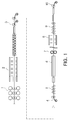
- FIG. 2 is a schematic view illustrating a shape-correcting and rolling process for high-strength steel according to a first illustrative example of the present disclosure.
- a strip is cooled to a winding temperature by a cooling device 2, and is then coiled as a coil by a coiler 3.
- the coil is transferred to a yard for a temperature adjusting process 20. That is, the coil is placed on a yard.
- the temperature adjusting process 20 the temperature of the coil (please refer to reference letter C in FIG. 8B ) is continuously measured, and in a state in which the coil has a predetermined temperature, for example, a temperature of 150°C or higher, the coil is transferred to a shape-correcting line through a second transfer process.
- the coil is unwound using a pay-off reel 30, and the strip unwounded from the coil undergoes a scale removing process in which scale is removed from the strip by using a shot blaster 31. Thereafter, the temperature of the strip is uniformized using a heating device 32, and then the strip is first rolled by a rolling mill 33 and is then shape-corrected by a skin pass mill 40. Next, the strip is rewound by a coiler 35.
- the skin pass mill 40 uses heat pipe rollers 100 to correct the shape of the strip.
- Thermal crowns of the heat pipe rollers 100 may be maintained at a constant level even in the case that the strip introduced between the heat pipe rollers 100 has a temperature of 150°C or higher, and since the strip has a temperature of 150°C or higher, the shape of the strip may be easily corrected even in the case that the strip is a high-strength steel strip.
- the rewound coil is directly subjected to a rolling process in warm-working conditions, in which the strip is unwound from the coil using a pay-off reel 50 and is then rolled by six to eight rolling mills 51.
- the hot rolling mills 1, the cooling device 2, and the coiler 3 are the same as those of the related art, and thus detailed descriptions thereof will be omitted.
- a time necessary for a cooling process 20 may be reduced.
- the rate of cooling is relatively high at high temperature and relatively low at low temperature, the time necessary for the cooling process 20 may be markedly reduced to about one day, as compared to the related art, requiring three to five days.
- the flow of coils may be improved in the yard in which the cooling process 20 is performed, and thus the amount of inventory may be reduced.
- the cooling process 20 will be explained later in detail with reference to FIGS. 8A and 8B .
- the strip passes through the heating device 32.
- the heating device 32 may not heat the strip to a constant temperature.
- the heating device 32 may be an induction heater.
- the rolling mill 33 performs a one-step rolling process at a reduction ratio of about 20% to about 30%. If the reduction ratio is greater than about 30%, shape errors may be increased to a degree to which the shape errors may not be corrected by the skin pass mill 40. Since the strip having a high degree of strength is rolled by the rolling mill 33 at a temperature of 150°C or higher, the effect of rolling may be relatively large, as compared to the case in which the strip is rolled in a later process. Therefore, a wide and thin final product may be obtained.
- the strip After passing though the rolling mill 33, the strip is introduced to the skin pass mill 40 including the heat pipe rollers 100.
- the skin pass mill 40 since the skin pass mill 40 includes the heat pipe rollers 100, the skin pass mill 40 may be operated free from the temperature of the strip introduced to the skin pass mill 40. That is, although the strip has a relatively high temperature, the skin pass mill 40 may properly correct the shape of the strip.
- the heat pipe rollers 100 uniformly increase the overall temperature of rolls, thereby uniformizing thermal crown shapes and completely performing a shape-correcting process regardless of the temperature of an introduced strip or the number of rolled strips. The heat pipe rollers 100 will be described later in detail with reference to FIGS. 3 to 7 .
- the strip After passing through the rolling mill 33 and the skin pass mill 40, the strip is rewound as a coil by the coiler 35, and then transferred for a rolling process.
- the coil processed along the shape-correcting line is directly subjected to the rolling process. Therefore, the rolling process may be performed within a warm-working temperature range. However, after an additional cooling process, the rolling process may be performed as a cold rolling process.
- FIGS. 3A to 7 illustrate a heat pipe roller 100 of the present disclosure.
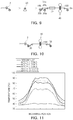
- FIGS. 3A and 3B are a longitudinal sectional view and a cross sectional view illustrating a heat pipe 110 of the heat pipe roller 100.
- FIG. 4 is a graph illustrating the yield strength of high-strength steel with reference to temperature.
- FIG. 5 is a front view illustrating the heat pipe roller 100 of the present disclosure.
- FIG. 6 is a side view illustrating the heat pipe roller 100 of the present disclosure.
- FIG. 7 is a view illustrating the heat pipe roller 100 in which heat pipes 110 are installed.
- each heat pipe 110 includes: a pipe 111 in which a vacuum is formed; and grooves 112 formed in the pipe 111 and filled with pure water. If the heat pipe 110 receives heat from a heating unit, the pure water evaporates, and a center region 113a of the heat pipe 110 is filled with steam. Since the steam filled in the center region 113a may increase pressure in the center region 113a, the steam moves to both end regions 113b having a low pressure and cools into pure water. Meanwhile, if the pure water filled in the grooves 112 is evaporated by heat, the pure water condensed from steam in the end regions 113b is moved back to the center region 113a by the capillary action of the grooves 112.
- heat transferred from the heating unit may be uniformly distributed throughout the heat pipe 110.
- the yield strength of high-strength steel considerably decreases at a temperature of 150°C or higher. That is, at room temperature or a temperature of about 100°C, the yield strength of high-strength steel does not considerably decrease, and thus the effect of shape correction of high-strength steel is low.
- strips having a temperature of at least 150°C are used.
- strips having a temperature lower than 150°C may be used. In this case, strips of high-strength steel are heated to a temperature lower than a phase transformation temperature of the high-strength steel.
- the heat pipe roller 100 of the present disclosure is similar to a general shape-correcting roll except that the heat pipes 110 are installed in a journal 104 between a rolling portion 102 and neck portions 103.
- Each of the heat pipes 110 may penetrate the rolling portion 102.
- first heat pipes 105 may be inserted from one end of the rolling portion 102
- second heat pipes 106 may be inserted from the other end of the rolling portion 102.
- the first and second heat pipes 105 and 106 may be alternately arranged in the circumferential direction of the rolling portion 102 for structural stability and benefits in manufacturing processes. That is, it may be advantageous to form insertion tubes of the first and second heat pipes 105 and 106 in such a manner that the insertion tubes do not meet each other, and in this case, the formation of cracks may be prevented even in the case that the load of a rolling process is repeatedly applied to the first and second heat pipes 105 and 106.
- first and second heat pipes 105 and 106 may overlap each other in a center region of the rolling portion 102.
- the temperature of a rolling roll is generally highest in a center region thereof. Therefore, if the first and second heat pipes 105 and 106 overlap each other in the center region of the rolling portion 102, the temperature of the center region of the rolling portion 102 may be effectively lowered, and thus the temperature difference between regions of the heat pipe roller 100 may be lowered.
- the shape of the heat pipe roller 100 may not be varied according to temperature. That is, the temperature difference between a center region and both end regions of the heat pipe roller 100 may be lowed. In other words, the temperature difference along the heat pipe roller 100 may be constantly maintained regardless of the temperature of a strip supplied to the heat pipe roller 100.
- the center region of the rolling portion 102 may be maintained at a temperature of about 65°C, and when the edges of the rolling portion 102 have a temperature of 70°C, the center region of the rolling portion 102 may be maintained at a temperature of about 85°C, so as to maintain the temperature difference between the center region and edges of the rolling portion 102 at a constant level. Therefore, a thermal crown shape caused by a temperature difference may be constantly maintained.
- the heat pipes 110 of the heat pipe roller 100 pure water evaporates into steam in a hot center region, and the steam moves to ends due to an increased pressure in the hot center region. Then, the steam condenses into pure water at the ends due to a low temperature, and the pure water moves back to the center region by the capillary action. As these actions are repeated, heat may be transferred from the center to edges of the heat pipe roller 100 by the evaporation and condensation of pure water, and thus the heat pipe roller 100 may have a uniform widthwise temperature distribution.
- FIGS. 8A and 8B illustrate a skid useable in a yard in the above-described cooling process 20 of the present disclosure.
- the skid is usable in the cooling process 20 of the present disclosure.
- a main body 21 of the skid includes a support surface 22 to receive a coil C thereon, and a penetration hole 27 is formed in the main body 21.
- a temperature sensor 25 is disposed in the penetration hole 27.
- the temperature sensor 25 measures the temperature of the coil C and transmits the measured temperature to a monitoring unit (control unit) 28.
- the monitoring unit 28 compares the temperature of the coil C with a predetermined temperature range, and if the temperature of the coil C is within the temperature range, the coil C is transferred away from the yard and coupled to a pay-off reel.
- the temperature range may be properly determined. For example, it may be preferable that the temperature range be set to equal to or higher than 150°C in consideration of cooling of the coil C when the coil C is unwound from the pay-off reel.
- FIG. 9 illustrates a second illustrative example of the present disclosure.
- a coil wound by a coiler 3 in a hot rolling process is transferred to a yard for a temperature adjusting process 20 in a first transfer process.
- the temperature of the coil (please refer to reference letter C in FIG. 8B ) is continuously measured, and in a state in which the coil has a predetermined temperature, for example, a temperature of 150°C or higher, the coil is transferred to a shape-correcting line through a second transfer process.
- a plurality of coils coupled to a plurality of pay-off reels 30a and 30b are sequentially unwound. Since an amount of time necessary for unwinding a coil after unwinding a previous coil is relatively long compared to an amount of time necessary for coupling the coils to the pay-off reels 30a and 30b, heat insulation covers 34a and 34b are used to maintain the temperature of the coils coupled to the pay-off reels 30a and 30b until the coils are unwound from the pay-off reels 30a and 30b. In other words, a heat insulating process may be performed using the heat insulation covers 34a and 34b to maintain the temperature of the coils coupled to the pay-off reels 30a and 30b.
- the heat insulation covers 34a and 34b may be moved away from the pay-off reels 30a and 30b when the coils are unwound from the pay-off reels 30a and 30b. However, the heat insulation covers 34a and 34b may not be moved away from the pay-off reels 30a and 30b to maintain the temperature of the coils during unwinding of the coils.
- Each strip unwound from the coils of the pay-off reels 30a and 30b passes through a heating device 32 in which the temperature of the strip is uniformized, and the shape of the strip is corrected by a skin pass mill 40. Thereafter, the strip is rewound by a coiler 35.
- the skin pass mill 40 uses heat pipe rollers 100 to correct the shape of the strip.
- a thermal crown of the heat pipe rollers 100 may be maintained at a constant level even in the case that the strip introduced between the heat pipe rollers 100 has a temperature of 150°C or higher, and since the strip has a temperature of 150°C or higher, the shape of the strip may be easily corrected even in the case that the strip is a high-strength steel strip.
- FIG. 10 illustrates a third illustrative exampleof the present disclosure.
- a coil wound by a coiler 3 in a hot rolling process is directly transferred to a shape-correcting device without a cooling process 20. That is, the coil is directly wound from a pay-off reel.
- a single device functions as a coiler and a pay-off reel.
- a coiler and a pay-off reel may be used, and a coil wound by the coiler may be directly transferred to the pay-off reel. That is, as long as a coil processed through a hot rolling process is directly transferred to the shape-correcting device through a direct transfer process, any configuration may be used.
- a strip unwound from a coil as described above is directly fed into a skin pass mill 40 for correcting the shape of the strip, and then the strip is rewound by a coiler 35.
- the skin pass mill 40 includes heat pipe rollers 100. Therefore, the skin pass mill 40 is free from the temperature of the strip, and thus even in the case that the strip has a high temperature, the shape of the strip may be stably corrected.
- the yield strength of the strip decreases as the temperature of the strip increases, the shape of the strip may be smoothly corrected.
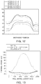
- FIG. 11 is a graph illustrating the temperature of a roll of a shape-correcting device of the related art with respect to the widthwise position of the roll when a strip having a temperature of 100°C to 120°C is corrected using the roll after different numbers of coils are processed.
- FIG. 12 is a graph illustrating the temperature of a roll of a shape-correcting device of the present disclosure with respect to the widthwise position of the roll when a strip having a temperature of 100°C to 140°C is corrected using the roll after different numbers of coils are processed.
- the temperature difference between a center region and edges of the roll ranges from 35°C to 50°C, and the temperature difference increases as the number of processed coils increases.
- the temperature difference between a center region and edges of the heat pipe roller is constantly maintained within the range of about 20°C to about 25°C.
- the temperature difference along the width of the heat pipe roller of the present disclosure is low.
- the temperature difference along the width of the heat pipe roller of the present disclosure may be constantly maintained even in the case that the overall temperature of the heat pipe roller increases.
- FIG. 13 is a graph illustrating thermal crowns of a shape-correcting device of the related art and the shape-correcting device of the present disclosure.
- thermal crowns of the heat pipe rollers are markedly small.
- 150- ⁇ m thermal crowns are formed based on a center region thereof.
- thermal crown having a dimension of about 15 ⁇ m is formed. That is, the thermal crowns of the heat pipe rollers 100 of the present disclosure are merely about 1/10 the thermal crowns of general rolls.
- FIGS. 14 to 17 are images of an actual strip.
- FIG. 14 is an image of a strip taken after a hot rolling process.
- FIG. 15 is another image of the strip of FIG. 14 taken after the strip had passed through a shape-correcting device of the related art at room temperature.
- FIG. 16 is another image of the strip of FIG. 14 taken after the strip had passed through the shape-correcting device of the related art at a warm-working temperature.
- FIG. 17 is another image of the strip of FIG. 14 after the strip had passed through the shape-correcting device of the present disclosure.
- the strip processed through a hot rolling process had edge waves.
- the edge waves of the strip remained after the strip had passed through the shape-correcting device of the related art at room temperature (please refer to FIG. 15 ).
- the strip of FIG. 14 had passed through the shape-correcting device of the related art within the temperature range of 130°C to 190°C, severe central waves were formed on the strip as shown in FIG. 16 (please refer to the circles of FIG 16 ).
- the load of a later process may be reduced, and the strip may be less cut in the later process, thereby improving overall process efficiency.
- Table 1 illustrates samples prepared using shape-correcting devices and methods of the related art and the present disclosure.
- Steel type Roll type Strip temperature (°C) Number of experiment s (coils) Average cutting amount (m) *CS 1 1180CP General roll Room temperature 15 37.1 CS 2 980DP General roll Room temperature 33 63.5 **IS 1 1180CP Heat pipe roller 150 15 0 IS 2 980DP Heat pipe roller 150 100 2.8 *CS: Comparative Sample, **IS: Inventive Sample
- the average amount of cutting was 63.5 m.
- the average amount of cutting was only 2.8 m when one hundred coils were shape-corrected.
- the shape-correcting and rolling method or the shape-correcting device of the present disclosure has remarkable effects on high-strength steel compared to methods or devices of the related art. Particularly, cutting lengths may be markedly reduced, and high-strength steel may be formed into wide and thin sheets.
Landscapes
- Engineering & Computer Science (AREA)
- Mechanical Engineering (AREA)
- Chemical & Material Sciences (AREA)
- Physics & Mathematics (AREA)
- Thermal Sciences (AREA)
- Crystallography & Structural Chemistry (AREA)
- Materials Engineering (AREA)
- Metallurgy (AREA)
- Organic Chemistry (AREA)
- Metal Rolling (AREA)
- Reduction Rolling/Reduction Stand/Operation Of Reduction Machine (AREA)
- Winding, Rewinding, Material Storage Devices (AREA)
Applications Claiming Priority (2)
| Application Number | Priority Date | Filing Date | Title |
|---|---|---|---|
| KR1020120150135A KR101449180B1 (ko) | 2012-12-21 | 2012-12-21 | 고강도강의 형상 교정 및 압연 방법과 형상 교정 장치 |
| PCT/KR2012/011542 WO2014098297A1 (ko) | 2012-12-21 | 2012-12-27 | 고강도강의 형상 교정 및 압연 방법과 형상 교정 장치 |
Publications (3)
| Publication Number | Publication Date |
|---|---|
| EP2937156A1 EP2937156A1 (en) | 2015-10-28 |
| EP2937156A4 EP2937156A4 (en) | 2016-05-04 |
| EP2937156B1 true EP2937156B1 (en) | 2019-09-25 |
Family
ID=50978591
Family Applications (1)
| Application Number | Title | Priority Date | Filing Date |
|---|---|---|---|
| EP12890177.4A Active EP2937156B1 (en) | 2012-12-21 | 2012-12-27 | Shape-correcting device for high-strength steel |
Country Status (6)
| Country | Link |
|---|---|
| US (1) | US10086418B2 (ko) |
| EP (1) | EP2937156B1 (ko) |
| JP (1) | JP6026014B2 (ko) |
| KR (1) | KR101449180B1 (ko) |
| CN (1) | CN104870115B (ko) |
| WO (1) | WO2014098297A1 (ko) |
Families Citing this family (8)
| Publication number | Priority date | Publication date | Assignee | Title |
|---|---|---|---|---|
| EP2982453A1 (de) * | 2014-08-06 | 2016-02-10 | Primetals Technologies Austria GmbH | Einstellen eines gezielten Temperaturprofiles an Bandkopf und Bandfuß vor dem Querteilen eines Metallbands |
| CN104399781B (zh) * | 2014-11-27 | 2016-08-17 | 武汉钢铁(集团)公司 | 一种消除低合金高强钢屈服平台的方法 |
| KR102218420B1 (ko) * | 2019-07-16 | 2021-02-19 | 주식회사 포스코 | 단조롤 기반 히트 파이프롤 및 그 제조방법 |
| CN111575452A (zh) * | 2020-05-21 | 2020-08-25 | 山东泰山钢铁集团有限公司 | 一种降低10Cr17不锈钢热轧酸洗表面粗糙度的方法 |
| CN113118783B (zh) * | 2020-05-31 | 2022-11-11 | 日照宝华新材料有限公司 | 一种1.5~4mm规格低碳钢横折缺陷控制方法 |
| CN112795766B (zh) * | 2020-12-09 | 2022-05-27 | 北京星航机电装备有限公司 | 一种高温合金焊接件退火校形方法 |
| CN113245371B (zh) * | 2021-06-30 | 2022-07-19 | 燕山大学 | 一种改善冷轧板带边降的电磁调控轧辊 |
| CN114769366B (zh) * | 2022-05-12 | 2024-02-20 | 武汉钢铁有限公司 | 一种改善取向钢成品板形的矫直系统及其控制方法 |
Family Cites Families (31)
| Publication number | Priority date | Publication date | Assignee | Title |
|---|---|---|---|---|
| CA1004066A (en) | 1974-03-19 | 1977-01-25 | Nippon Steel Corporation | Method of and apparatus for controlling the shape of rolled objects in the rolling of plate, sheet, strip and the like |
| JPS579501A (en) | 1980-06-19 | 1982-01-19 | Kawasaki Steel Corp | Rolling plant for material to be rolled |
| JPS61269901A (ja) | 1985-05-23 | 1986-11-29 | Kawasaki Steel Corp | 冷延鋼帯の調質圧延方法 |
| US4793172A (en) * | 1986-02-24 | 1988-12-27 | Italimpianti Of America Incorporated | Thermal crown controlled rolls |
| US5119886A (en) | 1989-10-25 | 1992-06-09 | The Texas A&M University System | Heat transfer cylinder |
| JPH0770351B2 (ja) | 1990-11-21 | 1995-07-31 | 三菱電機株式会社 | 均熱ロール装置 |
| JPH06304656A (ja) * | 1993-04-27 | 1994-11-01 | Seikosha Co Ltd | ローラ矯正装置 |
| JPH07204704A (ja) | 1994-01-11 | 1995-08-08 | Ishikawajima Harima Heavy Ind Co Ltd | 圧延設備 |
| CA2202616C (en) * | 1994-10-20 | 2001-01-23 | Fritz-Peter Pleschiutschnigg | Process and device for producing a steel strip with the properties of a cold-rolled product |
| KR100207067B1 (ko) | 1996-05-18 | 1999-07-01 | 지원국 | 전기 가열식 금속 스트립 압연기 |
| NL1007739C2 (nl) * | 1997-12-08 | 1999-06-09 | Hoogovens Staal Bv | Werkwijze en inrichting voor het vervaardigen van een stalen band met hoge sterkte. |
| JPH105809A (ja) | 1996-06-25 | 1998-01-13 | Nkk Corp | 熱延鋼帯の調質圧延方法 |
| JPH10192915A (ja) | 1997-01-09 | 1998-07-28 | Mitsubishi Heavy Ind Ltd | 圧延機及び圧延設備 |
| EP0972427A1 (en) * | 1997-01-13 | 2000-01-19 | American Roller Company | Heated roller with integral heat pipe |
| JP3263359B2 (ja) * | 1997-04-04 | 2002-03-04 | 川崎製鉄株式会社 | シートバーの大単重熱間圧延方法 |
| JP2000054098A (ja) | 1998-07-31 | 2000-02-22 | Nkk Corp | めっき密着性及び耐ブリスター性に優れた熱延板下地溶融亜鉛めっき鋼板の製造方法及びその製造装置 |
| JP2000051910A (ja) * | 1998-08-10 | 2000-02-22 | Sumitomo Metal Ind Ltd | 連続化熱間圧延設備 |
| KR20000010065U (ko) | 1998-11-14 | 2000-06-15 | 이구택 | 열연 스킨패스 롤 히터장치 |
| DE19933610A1 (de) | 1999-07-17 | 2001-01-25 | Bwg Bergwerk Walzwerk | Verfahren zum Planieren von Metallbändern |
| JP2001105006A (ja) | 1999-09-30 | 2001-04-17 | Sumitomo Metal Ind Ltd | 厚鋼板の製造方法およびその装置 |
| KR200196021Y1 (ko) | 2000-04-10 | 2000-09-15 | 이성영 | 간판 형광등의 점등관 접속구 |
| KR100496607B1 (ko) | 2000-12-27 | 2005-06-22 | 주식회사 포스코 | 열연코일의 제조방법 및 그 장치 |
| JP4449455B2 (ja) | 2001-10-10 | 2010-04-14 | Jfeスチール株式会社 | 鋼板の製造方法 |
| JP4692882B2 (ja) | 2005-08-11 | 2011-06-01 | 住友金属工業株式会社 | マグネシウム板とマグネシウム板の製造方法 |
| JP2008213015A (ja) | 2007-03-07 | 2008-09-18 | Jfe Steel Kk | 冷延鋼板の製造方法および鋼板の連続処理ライン |
| DE102008010062A1 (de) | 2007-06-22 | 2008-12-24 | Sms Demag Ag | Verfahren zum Warmwalzen und zur Wärmebehandlung eines Bandes aus Stahl |
| KR101053414B1 (ko) | 2008-07-04 | 2011-08-01 | 주식회사 포스코 | 열연강대의 스케일 제거방법 및 제거설비 |
| JP5391786B2 (ja) | 2009-04-06 | 2014-01-15 | 新日鐵住金株式会社 | 鋼板の形状矯正方法及び装置 |
| CN101670372B (zh) | 2009-09-25 | 2011-01-26 | 首钢总公司 | 一种消除热轧高强钢板形缺陷的方法 |
| JP5512326B2 (ja) | 2010-02-19 | 2014-06-04 | 株式会社神戸製鋼所 | 金属冷却装置および金属冷却方法 |
| JP5757104B2 (ja) | 2011-02-24 | 2015-07-29 | 住友電気工業株式会社 | マグネシウム合金材及びその製造方法 |
-
2012
- 2012-12-21 KR KR1020120150135A patent/KR101449180B1/ko active IP Right Grant
- 2012-12-27 JP JP2015549232A patent/JP6026014B2/ja active Active
- 2012-12-27 US US14/647,439 patent/US10086418B2/en active Active
- 2012-12-27 CN CN201280077682.5A patent/CN104870115B/zh active Active
- 2012-12-27 WO PCT/KR2012/011542 patent/WO2014098297A1/ko active Application Filing
- 2012-12-27 EP EP12890177.4A patent/EP2937156B1/en active Active
Non-Patent Citations (1)
| Title |
|---|
| None * |
Also Published As
| Publication number | Publication date |
|---|---|
| KR101449180B1 (ko) | 2014-10-08 |
| JP2016501133A (ja) | 2016-01-18 |
| US10086418B2 (en) | 2018-10-02 |
| CN104870115B (zh) | 2017-10-31 |
| CN104870115A (zh) | 2015-08-26 |
| US20150306645A1 (en) | 2015-10-29 |
| WO2014098297A1 (ko) | 2014-06-26 |
| EP2937156A1 (en) | 2015-10-28 |
| KR20140080931A (ko) | 2014-07-01 |
| EP2937156A4 (en) | 2016-05-04 |
| JP6026014B2 (ja) | 2016-11-16 |
Similar Documents
| Publication | Publication Date | Title |
|---|---|---|
| EP2937156B1 (en) | Shape-correcting device for high-strength steel | |
| EP2213387B1 (en) | Magnesium alloy hot-rolling mill | |
| CN111330974B (zh) | 一种厚规格x70管线钢钢卷的热连轧生产方法 | |
| US9523135B2 (en) | Method of cold-rolling steel sheet and cold-rolling facility | |
| CN101628297A (zh) | 钛板卷的可逆式热轧工艺 | |
| CN108787746B (zh) | 一种连挤连轧控温生产镁合金产品的生产线 | |
| EP1196256B1 (en) | Integrated continuous casting and in-line hot rolling process, as well as relative process with intermediate coiling and uncoiling of the pre-strip | |
| TWI799028B (zh) | 冷軋鋼板的製造方法及製造設備 | |
| JP6137109B2 (ja) | 熱延鋼板の粗圧延方法 | |
| EP3216881B1 (en) | Steel sheet manufacturing method and steel sheet manufacturing device | |
| WO1998031482A1 (en) | Method and apparatus for rolling strip or plate | |
| JP2010162595A (ja) | 高強度厚肉熱延鋼板の巻き取り設備および巻き取り方法 | |
| KR101482353B1 (ko) | 히트 파이프롤 및 그의 제작 방법 | |
| JP2005296973A (ja) | 熱延鋼板の製造方法とその装置 | |
| TWI797912B (zh) | 冷軋鋼板的製造方法及製造設備 | |
| JP2009195925A (ja) | 熱間圧延方法および熱延金属帯ならびに電縫管 | |
| JP5407698B2 (ja) | 厚鋼板の製造方法および製造設備 | |
| KR100941848B1 (ko) | 강판의 폭을 압연하는 조압연 방법 | |
| RU2491140C2 (ru) | Способ горячей прокатки полос и комбинированный полунепрерывный стан для его осуществления | |
| JP3265972B2 (ja) | 薄物熱延鋼板の製造方法およびその設備 | |
| US11241726B2 (en) | Hot-rolled steel sheet and method for manufacturing same | |
| JP3351239B2 (ja) | 熱延鋼帯の圧延方法および装置 | |
| JP6102506B2 (ja) | 板幅方向に板厚差を有する差厚鋼板の製造装置及び製造方法 | |
| JP3317164B2 (ja) | 熱延鋼帯の製造方法およびその方法に使用する熱間圧延設備列 | |
| RU2480528C1 (ru) | Способ охлаждения движущейся стальной горячекатаной полосы |
Legal Events
| Date | Code | Title | Description |
|---|---|---|---|
| PUAI | Public reference made under article 153(3) epc to a published international application that has entered the european phase |
Free format text: ORIGINAL CODE: 0009012 |
|
| 17P | Request for examination filed |
Effective date: 20150618 |
|
| AK | Designated contracting states |
Kind code of ref document: A1 Designated state(s): AL AT BE BG CH CY CZ DE DK EE ES FI FR GB GR HR HU IE IS IT LI LT LU LV MC MK MT NL NO PL PT RO RS SE SI SK SM TR |
|
| AX | Request for extension of the european patent |
Extension state: BA ME |
|
| DAX | Request for extension of the european patent (deleted) | ||
| A4 | Supplementary search report drawn up and despatched |
Effective date: 20160405 |
|
| RIC1 | Information provided on ipc code assigned before grant |
Ipc: C21D 8/02 20060101ALI20160330BHEP Ipc: B21C 47/00 20060101ALI20160330BHEP Ipc: B21B 45/06 20060101ALI20160330BHEP Ipc: B21D 1/05 20060101AFI20160330BHEP Ipc: B21B 1/26 20060101ALI20160330BHEP |
|
| STAA | Information on the status of an ep patent application or granted ep patent |
Free format text: STATUS: EXAMINATION IS IN PROGRESS |
|
| 17Q | First examination report despatched |
Effective date: 20170206 |
|
| REG | Reference to a national code |
Ref country code: DE Ref legal event code: R079 Ref document number: 602012064400 Country of ref document: DE Free format text: PREVIOUS MAIN CLASS: B21D0001050000 Ipc: B21B0001220000 |
|
| GRAP | Despatch of communication of intention to grant a patent |
Free format text: ORIGINAL CODE: EPIDOSNIGR1 |
|
| STAA | Information on the status of an ep patent application or granted ep patent |
Free format text: STATUS: GRANT OF PATENT IS INTENDED |
|
| RIC1 | Information provided on ipc code assigned before grant |
Ipc: B21B 15/00 20060101ALI20190311BHEP Ipc: C21D 8/02 20060101ALI20190311BHEP Ipc: B21B 45/06 20060101ALI20190311BHEP Ipc: B21C 47/02 20060101ALN20190311BHEP Ipc: B21D 1/05 20060101ALI20190311BHEP Ipc: B21B 1/22 20060101AFI20190311BHEP Ipc: B21C 47/16 20060101ALN20190311BHEP Ipc: B21D 1/02 20060101ALN20190311BHEP Ipc: B21C 47/00 20060101ALI20190311BHEP Ipc: B21B 27/08 20060101ALN20190311BHEP |
|
| INTG | Intention to grant announced |
Effective date: 20190412 |
|
| GRAS | Grant fee paid |
Free format text: ORIGINAL CODE: EPIDOSNIGR3 |
|
| GRAA | (expected) grant |
Free format text: ORIGINAL CODE: 0009210 |
|
| STAA | Information on the status of an ep patent application or granted ep patent |
Free format text: STATUS: THE PATENT HAS BEEN GRANTED |
|
| AK | Designated contracting states |
Kind code of ref document: B1 Designated state(s): AL AT BE BG CH CY CZ DE DK EE ES FI FR GB GR HR HU IE IS IT LI LT LU LV MC MK MT NL NO PL PT RO RS SE SI SK SM TR |
|
| REG | Reference to a national code |
Ref country code: GB Ref legal event code: FG4D |
|
| REG | Reference to a national code |
Ref country code: CH Ref legal event code: EP |
|
| REG | Reference to a national code |
Ref country code: AT Ref legal event code: REF Ref document number: 1183307 Country of ref document: AT Kind code of ref document: T Effective date: 20191015 |
|
| REG | Reference to a national code |
Ref country code: IE Ref legal event code: FG4D |
|
| REG | Reference to a national code |
Ref country code: DE Ref legal event code: R096 Ref document number: 602012064400 Country of ref document: DE |
|
| REG | Reference to a national code |
Ref country code: NL Ref legal event code: MP Effective date: 20190925 |
|
| PG25 | Lapsed in a contracting state [announced via postgrant information from national office to epo] |
Ref country code: LT Free format text: LAPSE BECAUSE OF FAILURE TO SUBMIT A TRANSLATION OF THE DESCRIPTION OR TO PAY THE FEE WITHIN THE PRESCRIBED TIME-LIMIT Effective date: 20190925 Ref country code: FI Free format text: LAPSE BECAUSE OF FAILURE TO SUBMIT A TRANSLATION OF THE DESCRIPTION OR TO PAY THE FEE WITHIN THE PRESCRIBED TIME-LIMIT Effective date: 20190925 Ref country code: SE Free format text: LAPSE BECAUSE OF FAILURE TO SUBMIT A TRANSLATION OF THE DESCRIPTION OR TO PAY THE FEE WITHIN THE PRESCRIBED TIME-LIMIT Effective date: 20190925 Ref country code: HR Free format text: LAPSE BECAUSE OF FAILURE TO SUBMIT A TRANSLATION OF THE DESCRIPTION OR TO PAY THE FEE WITHIN THE PRESCRIBED TIME-LIMIT Effective date: 20190925 Ref country code: BG Free format text: LAPSE BECAUSE OF FAILURE TO SUBMIT A TRANSLATION OF THE DESCRIPTION OR TO PAY THE FEE WITHIN THE PRESCRIBED TIME-LIMIT Effective date: 20191225 Ref country code: NO Free format text: LAPSE BECAUSE OF FAILURE TO SUBMIT A TRANSLATION OF THE DESCRIPTION OR TO PAY THE FEE WITHIN THE PRESCRIBED TIME-LIMIT Effective date: 20191225 |
|
| REG | Reference to a national code |
Ref country code: LT Ref legal event code: MG4D |
|
| PG25 | Lapsed in a contracting state [announced via postgrant information from national office to epo] |
Ref country code: LV Free format text: LAPSE BECAUSE OF FAILURE TO SUBMIT A TRANSLATION OF THE DESCRIPTION OR TO PAY THE FEE WITHIN THE PRESCRIBED TIME-LIMIT Effective date: 20190925 Ref country code: GR Free format text: LAPSE BECAUSE OF FAILURE TO SUBMIT A TRANSLATION OF THE DESCRIPTION OR TO PAY THE FEE WITHIN THE PRESCRIBED TIME-LIMIT Effective date: 20191226 Ref country code: RS Free format text: LAPSE BECAUSE OF FAILURE TO SUBMIT A TRANSLATION OF THE DESCRIPTION OR TO PAY THE FEE WITHIN THE PRESCRIBED TIME-LIMIT Effective date: 20190925 |
|
| PG25 | Lapsed in a contracting state [announced via postgrant information from national office to epo] |
Ref country code: PL Free format text: LAPSE BECAUSE OF FAILURE TO SUBMIT A TRANSLATION OF THE DESCRIPTION OR TO PAY THE FEE WITHIN THE PRESCRIBED TIME-LIMIT Effective date: 20190925 Ref country code: EE Free format text: LAPSE BECAUSE OF FAILURE TO SUBMIT A TRANSLATION OF THE DESCRIPTION OR TO PAY THE FEE WITHIN THE PRESCRIBED TIME-LIMIT Effective date: 20190925 Ref country code: ES Free format text: LAPSE BECAUSE OF FAILURE TO SUBMIT A TRANSLATION OF THE DESCRIPTION OR TO PAY THE FEE WITHIN THE PRESCRIBED TIME-LIMIT Effective date: 20190925 Ref country code: NL Free format text: LAPSE BECAUSE OF FAILURE TO SUBMIT A TRANSLATION OF THE DESCRIPTION OR TO PAY THE FEE WITHIN THE PRESCRIBED TIME-LIMIT Effective date: 20190925 Ref country code: RO Free format text: LAPSE BECAUSE OF FAILURE TO SUBMIT A TRANSLATION OF THE DESCRIPTION OR TO PAY THE FEE WITHIN THE PRESCRIBED TIME-LIMIT Effective date: 20190925 Ref country code: PT Free format text: LAPSE BECAUSE OF FAILURE TO SUBMIT A TRANSLATION OF THE DESCRIPTION OR TO PAY THE FEE WITHIN THE PRESCRIBED TIME-LIMIT Effective date: 20200127 Ref country code: IT Free format text: LAPSE BECAUSE OF FAILURE TO SUBMIT A TRANSLATION OF THE DESCRIPTION OR TO PAY THE FEE WITHIN THE PRESCRIBED TIME-LIMIT Effective date: 20190925 Ref country code: AL Free format text: LAPSE BECAUSE OF FAILURE TO SUBMIT A TRANSLATION OF THE DESCRIPTION OR TO PAY THE FEE WITHIN THE PRESCRIBED TIME-LIMIT Effective date: 20190925 |
|
| PG25 | Lapsed in a contracting state [announced via postgrant information from national office to epo] |
Ref country code: SM Free format text: LAPSE BECAUSE OF FAILURE TO SUBMIT A TRANSLATION OF THE DESCRIPTION OR TO PAY THE FEE WITHIN THE PRESCRIBED TIME-LIMIT Effective date: 20190925 Ref country code: SK Free format text: LAPSE BECAUSE OF FAILURE TO SUBMIT A TRANSLATION OF THE DESCRIPTION OR TO PAY THE FEE WITHIN THE PRESCRIBED TIME-LIMIT Effective date: 20190925 Ref country code: IS Free format text: LAPSE BECAUSE OF FAILURE TO SUBMIT A TRANSLATION OF THE DESCRIPTION OR TO PAY THE FEE WITHIN THE PRESCRIBED TIME-LIMIT Effective date: 20200224 Ref country code: CZ Free format text: LAPSE BECAUSE OF FAILURE TO SUBMIT A TRANSLATION OF THE DESCRIPTION OR TO PAY THE FEE WITHIN THE PRESCRIBED TIME-LIMIT Effective date: 20190925 |
|
| REG | Reference to a national code |
Ref country code: DE Ref legal event code: R097 Ref document number: 602012064400 Country of ref document: DE |
|
| PG2D | Information on lapse in contracting state deleted |
Ref country code: IS |
|
| PG25 | Lapsed in a contracting state [announced via postgrant information from national office to epo] |
Ref country code: DK Free format text: LAPSE BECAUSE OF FAILURE TO SUBMIT A TRANSLATION OF THE DESCRIPTION OR TO PAY THE FEE WITHIN THE PRESCRIBED TIME-LIMIT Effective date: 20190925 Ref country code: IS Free format text: LAPSE BECAUSE OF FAILURE TO SUBMIT A TRANSLATION OF THE DESCRIPTION OR TO PAY THE FEE WITHIN THE PRESCRIBED TIME-LIMIT Effective date: 20200126 |
|
| PLBE | No opposition filed within time limit |
Free format text: ORIGINAL CODE: 0009261 |
|
| REG | Reference to a national code |
Ref country code: CH Ref legal event code: PL |
|
| STAA | Information on the status of an ep patent application or granted ep patent |
Free format text: STATUS: NO OPPOSITION FILED WITHIN TIME LIMIT |
|
| REG | Reference to a national code |
Ref country code: BE Ref legal event code: MM Effective date: 20191231 |
|
| PG25 | Lapsed in a contracting state [announced via postgrant information from national office to epo] |
Ref country code: MC Free format text: LAPSE BECAUSE OF FAILURE TO SUBMIT A TRANSLATION OF THE DESCRIPTION OR TO PAY THE FEE WITHIN THE PRESCRIBED TIME-LIMIT Effective date: 20190925 |
|
| 26N | No opposition filed |
Effective date: 20200626 |
|
| GBPC | Gb: european patent ceased through non-payment of renewal fee |
Effective date: 20191227 |
|
| REG | Reference to a national code |
Ref country code: AT Ref legal event code: UEP Ref document number: 1183307 Country of ref document: AT Kind code of ref document: T Effective date: 20190925 |
|
| PG25 | Lapsed in a contracting state [announced via postgrant information from national office to epo] |
Ref country code: LU Free format text: LAPSE BECAUSE OF NON-PAYMENT OF DUE FEES Effective date: 20191227 Ref country code: IE Free format text: LAPSE BECAUSE OF NON-PAYMENT OF DUE FEES Effective date: 20191227 Ref country code: GB Free format text: LAPSE BECAUSE OF NON-PAYMENT OF DUE FEES Effective date: 20191227 |
|
| PG25 | Lapsed in a contracting state [announced via postgrant information from national office to epo] |
Ref country code: BE Free format text: LAPSE BECAUSE OF NON-PAYMENT OF DUE FEES Effective date: 20191231 Ref country code: SI Free format text: LAPSE BECAUSE OF FAILURE TO SUBMIT A TRANSLATION OF THE DESCRIPTION OR TO PAY THE FEE WITHIN THE PRESCRIBED TIME-LIMIT Effective date: 20190925 Ref country code: CH Free format text: LAPSE BECAUSE OF NON-PAYMENT OF DUE FEES Effective date: 20191231 Ref country code: LI Free format text: LAPSE BECAUSE OF NON-PAYMENT OF DUE FEES Effective date: 20191231 |
|
| PG25 | Lapsed in a contracting state [announced via postgrant information from national office to epo] |
Ref country code: CY Free format text: LAPSE BECAUSE OF FAILURE TO SUBMIT A TRANSLATION OF THE DESCRIPTION OR TO PAY THE FEE WITHIN THE PRESCRIBED TIME-LIMIT Effective date: 20190925 |
|
| PG25 | Lapsed in a contracting state [announced via postgrant information from national office to epo] |
Ref country code: MT Free format text: LAPSE BECAUSE OF FAILURE TO SUBMIT A TRANSLATION OF THE DESCRIPTION OR TO PAY THE FEE WITHIN THE PRESCRIBED TIME-LIMIT Effective date: 20190925 Ref country code: HU Free format text: LAPSE BECAUSE OF FAILURE TO SUBMIT A TRANSLATION OF THE DESCRIPTION OR TO PAY THE FEE WITHIN THE PRESCRIBED TIME-LIMIT; INVALID AB INITIO Effective date: 20121227 |
|
| PG25 | Lapsed in a contracting state [announced via postgrant information from national office to epo] |
Ref country code: TR Free format text: LAPSE BECAUSE OF FAILURE TO SUBMIT A TRANSLATION OF THE DESCRIPTION OR TO PAY THE FEE WITHIN THE PRESCRIBED TIME-LIMIT Effective date: 20190925 |
|
| PG25 | Lapsed in a contracting state [announced via postgrant information from national office to epo] |
Ref country code: MK Free format text: LAPSE BECAUSE OF FAILURE TO SUBMIT A TRANSLATION OF THE DESCRIPTION OR TO PAY THE FEE WITHIN THE PRESCRIBED TIME-LIMIT Effective date: 20190925 |
|
| REG | Reference to a national code |
Ref country code: DE Ref legal event code: R081 Ref document number: 602012064400 Country of ref document: DE Owner name: POSCO CO., LTD, POHANG-SI, KR Free format text: FORMER OWNER: POSCO, POHANG-SI, GYEONGSANGBUK-DO, KR Ref country code: DE Ref legal event code: R081 Ref document number: 602012064400 Country of ref document: DE Owner name: POSCO CO., LTD, POHANG- SI, KR Free format text: FORMER OWNER: POSCO, POHANG-SI, GYEONGSANGBUK-DO, KR Ref country code: DE Ref legal event code: R081 Ref document number: 602012064400 Country of ref document: DE Owner name: POSCO HOLDINGS INC., KR Free format text: FORMER OWNER: POSCO, POHANG-SI, GYEONGSANGBUK-DO, KR |
|
| REG | Reference to a national code |
Ref country code: AT Ref legal event code: PC Ref document number: 1183307 Country of ref document: AT Kind code of ref document: T Owner name: POSCO CO., LTD, KR Effective date: 20230228 |
|
| REG | Reference to a national code |
Ref country code: DE Ref legal event code: R081 Ref document number: 602012064400 Country of ref document: DE Owner name: POSCO CO., LTD, POHANG-SI, KR Free format text: FORMER OWNER: POSCO HOLDINGS INC., SEOUL, KR Ref country code: DE Ref legal event code: R081 Ref document number: 602012064400 Country of ref document: DE Owner name: POSCO CO., LTD, POHANG- SI, KR Free format text: FORMER OWNER: POSCO HOLDINGS INC., SEOUL, KR |
|
| PGFP | Annual fee paid to national office [announced via postgrant information from national office to epo] |
Ref country code: FR Payment date: 20230922 Year of fee payment: 12 |
|
| PGFP | Annual fee paid to national office [announced via postgrant information from national office to epo] |
Ref country code: DE Payment date: 20230920 Year of fee payment: 12 Ref country code: AT Payment date: 20231005 Year of fee payment: 12 |