EP2920292B1 - Vorrichtung und verfahren für dreidimensionale gewebemessungen auf basis eines kontrollierten medienstroms - Google Patents
Vorrichtung und verfahren für dreidimensionale gewebemessungen auf basis eines kontrollierten medienstroms Download PDFInfo
- Publication number
- EP2920292B1 EP2920292B1 EP13827054.1A EP13827054A EP2920292B1 EP 2920292 B1 EP2920292 B1 EP 2920292B1 EP 13827054 A EP13827054 A EP 13827054A EP 2920292 B1 EP2920292 B1 EP 2920292B1
- Authority
- EP
- European Patent Office
- Prior art keywords
- sample
- media
- well
- plunger
- disposed
- Prior art date
- Legal status (The legal status is an assumption and is not a legal conclusion. Google has not performed a legal analysis and makes no representation as to the accuracy of the status listed.)
- Active
Links
- 238000005259 measurement Methods 0.000 title claims description 36
- 238000000034 method Methods 0.000 title claims description 18
- 230000010412 perfusion Effects 0.000 claims description 45
- 239000012530 fluid Substances 0.000 claims description 39
- 239000007789 gas Substances 0.000 claims description 39
- 239000002609 medium Substances 0.000 claims description 21
- 238000004891 communication Methods 0.000 claims description 20
- 230000033001 locomotion Effects 0.000 claims description 18
- 229940088623 biologically active substance Drugs 0.000 claims description 10
- 238000004458 analytical method Methods 0.000 claims description 9
- 238000004113 cell culture Methods 0.000 claims description 8
- -1 hydrogen ions Chemical class 0.000 claims description 8
- 239000000203 mixture Substances 0.000 claims description 7
- UBAZGMLMVVQSCD-UHFFFAOYSA-N carbon dioxide;molecular oxygen Chemical compound O=O.O=C=O UBAZGMLMVVQSCD-UHFFFAOYSA-N 0.000 claims description 6
- 239000000126 substance Substances 0.000 claims description 5
- 239000012737 fresh medium Substances 0.000 claims description 4
- 239000001257 hydrogen Substances 0.000 claims description 3
- 229910052739 hydrogen Inorganic materials 0.000 claims description 3
- 239000011261 inert gas Substances 0.000 claims description 3
- 239000012092 media component Substances 0.000 claims description 3
- 230000035899 viability Effects 0.000 claims description 3
- 230000010261 cell growth Effects 0.000 claims description 2
- 239000000523 sample Substances 0.000 description 142
- 210000004027 cell Anatomy 0.000 description 40
- 210000001519 tissue Anatomy 0.000 description 35
- 238000012360 testing method Methods 0.000 description 18
- QVGXLLKOCUKJST-UHFFFAOYSA-N atomic oxygen Chemical compound [O] QVGXLLKOCUKJST-UHFFFAOYSA-N 0.000 description 17
- 239000001301 oxygen Substances 0.000 description 17
- 229910052760 oxygen Inorganic materials 0.000 description 17
- 150000001875 compounds Chemical class 0.000 description 13
- QGZKDVFQNNGYKY-UHFFFAOYSA-N Ammonia Chemical compound N QGZKDVFQNNGYKY-UHFFFAOYSA-N 0.000 description 12
- 239000011324 bead Substances 0.000 description 12
- 239000003814 drug Substances 0.000 description 12
- 229940079593 drug Drugs 0.000 description 12
- 230000006870 function Effects 0.000 description 10
- WQZGKKKJIJFFOK-GASJEMHNSA-N Glucose Natural products OC[C@H]1OC(O)[C@H](O)[C@@H](O)[C@@H]1O WQZGKKKJIJFFOK-GASJEMHNSA-N 0.000 description 9
- 241001559542 Hippocampus hippocampus Species 0.000 description 9
- 239000008103 glucose Substances 0.000 description 9
- CURLTUGMZLYLDI-UHFFFAOYSA-N Carbon dioxide Chemical compound O=C=O CURLTUGMZLYLDI-UHFFFAOYSA-N 0.000 description 8
- 230000002715 bioenergetic effect Effects 0.000 description 8
- 230000007246 mechanism Effects 0.000 description 8
- BMZRVOVNUMQTIN-UHFFFAOYSA-N Carbonyl Cyanide para-Trifluoromethoxyphenylhydrazone Chemical compound FC(F)(F)OC1=CC=C(NN=C(C#N)C#N)C=C1 BMZRVOVNUMQTIN-UHFFFAOYSA-N 0.000 description 7
- 206010028980 Neoplasm Diseases 0.000 description 7
- 229910002092 carbon dioxide Inorganic materials 0.000 description 7
- 230000002503 metabolic effect Effects 0.000 description 7
- 229910021529 ammonia Inorganic materials 0.000 description 6
- 229920000642 polymer Polymers 0.000 description 6
- 230000004044 response Effects 0.000 description 6
- GEHJYWRUCIMESM-UHFFFAOYSA-L sodium sulfite Chemical compound [Na+].[Na+].[O-]S([O-])=O GEHJYWRUCIMESM-UHFFFAOYSA-L 0.000 description 6
- 239000000243 solution Substances 0.000 description 6
- 206010021143 Hypoxia Diseases 0.000 description 5
- 238000003556 assay Methods 0.000 description 5
- 230000001276 controlling effect Effects 0.000 description 5
- 230000007613 environmental effect Effects 0.000 description 5
- 230000004907 flux Effects 0.000 description 5
- 230000002706 hydrostatic effect Effects 0.000 description 5
- 238000002347 injection Methods 0.000 description 5
- 239000007924 injection Substances 0.000 description 5
- 239000000463 material Substances 0.000 description 5
- 230000008901 benefit Effects 0.000 description 4
- 239000012472 biological sample Substances 0.000 description 4
- 230000002255 enzymatic effect Effects 0.000 description 4
- 230000001146 hypoxic effect Effects 0.000 description 4
- 238000003780 insertion Methods 0.000 description 4
- 230000037431 insertion Effects 0.000 description 4
- NOESYZHRGYRDHS-UHFFFAOYSA-N insulin Chemical compound N1C(=O)C(NC(=O)C(CCC(N)=O)NC(=O)C(CCC(O)=O)NC(=O)C(C(C)C)NC(=O)C(NC(=O)CN)C(C)CC)CSSCC(C(NC(CO)C(=O)NC(CC(C)C)C(=O)NC(CC=2C=CC(O)=CC=2)C(=O)NC(CCC(N)=O)C(=O)NC(CC(C)C)C(=O)NC(CCC(O)=O)C(=O)NC(CC(N)=O)C(=O)NC(CC=2C=CC(O)=CC=2)C(=O)NC(CSSCC(NC(=O)C(C(C)C)NC(=O)C(CC(C)C)NC(=O)C(CC=2C=CC(O)=CC=2)NC(=O)C(CC(C)C)NC(=O)C(C)NC(=O)C(CCC(O)=O)NC(=O)C(C(C)C)NC(=O)C(CC(C)C)NC(=O)C(CC=2NC=NC=2)NC(=O)C(CO)NC(=O)CNC2=O)C(=O)NCC(=O)NC(CCC(O)=O)C(=O)NC(CCCNC(N)=N)C(=O)NCC(=O)NC(CC=3C=CC=CC=3)C(=O)NC(CC=3C=CC=CC=3)C(=O)NC(CC=3C=CC(O)=CC=3)C(=O)NC(C(C)O)C(=O)N3C(CCC3)C(=O)NC(CCCCN)C(=O)NC(C)C(O)=O)C(=O)NC(CC(N)=O)C(O)=O)=O)NC(=O)C(C(C)CC)NC(=O)C(CO)NC(=O)C(C(C)O)NC(=O)C1CSSCC2NC(=O)C(CC(C)C)NC(=O)C(NC(=O)C(CCC(N)=O)NC(=O)C(CC(N)=O)NC(=O)C(NC(=O)C(N)CC=1C=CC=CC=1)C(C)C)CC1=CN=CN1 NOESYZHRGYRDHS-UHFFFAOYSA-N 0.000 description 4
- 230000036284 oxygen consumption Effects 0.000 description 4
- 238000003860 storage Methods 0.000 description 4
- JVTAAEKCZFNVCJ-UHFFFAOYSA-M Lactate Chemical compound CC(O)C([O-])=O JVTAAEKCZFNVCJ-UHFFFAOYSA-M 0.000 description 3
- 229940123973 Oxygen scavenger Drugs 0.000 description 3
- 239000004793 Polystyrene Substances 0.000 description 3
- XSQUKJJJFZCRTK-UHFFFAOYSA-N Urea Chemical compound NC(N)=O XSQUKJJJFZCRTK-UHFFFAOYSA-N 0.000 description 3
- 239000012491 analyte Substances 0.000 description 3
- 238000004364 calculation method Methods 0.000 description 3
- 239000004202 carbamide Substances 0.000 description 3
- 238000000423 cell based assay Methods 0.000 description 3
- 230000000875 corresponding effect Effects 0.000 description 3
- 230000034659 glycolysis Effects 0.000 description 3
- 230000002401 inhibitory effect Effects 0.000 description 3
- 239000012528 membrane Substances 0.000 description 3
- 230000004898 mitochondrial function Effects 0.000 description 3
- 235000015097 nutrients Nutrition 0.000 description 3
- 229920000139 polyethylene terephthalate Polymers 0.000 description 3
- 239000005020 polyethylene terephthalate Substances 0.000 description 3
- 229920002223 polystyrene Polymers 0.000 description 3
- 230000000241 respiratory effect Effects 0.000 description 3
- 238000012216 screening Methods 0.000 description 3
- 230000011664 signaling Effects 0.000 description 3
- 235000010265 sodium sulphite Nutrition 0.000 description 3
- 239000002699 waste material Substances 0.000 description 3
- MNULEGDCPYONBU-WMBHJXFZSA-N (1r,4s,5e,5'r,6'r,7e,10s,11r,12s,14r,15s,16s,18r,19s,20r,21e,25s,26r,27s,29s)-4-ethyl-11,12,15,19-tetrahydroxy-6'-[(2s)-2-hydroxypropyl]-5',10,12,14,16,18,20,26,29-nonamethylspiro[24,28-dioxabicyclo[23.3.1]nonacosa-5,7,21-triene-27,2'-oxane]-13,17,23-trio Polymers O([C@@H]1CC[C@@H](/C=C/C=C/C[C@H](C)[C@@H](O)[C@](C)(O)C(=O)[C@H](C)[C@@H](O)[C@H](C)C(=O)[C@H](C)[C@@H](O)[C@H](C)/C=C/C(=O)O[C@H]([C@H]2C)[C@H]1C)CC)[C@]12CC[C@@H](C)[C@@H](C[C@H](C)O)O1 MNULEGDCPYONBU-WMBHJXFZSA-N 0.000 description 2
- MNULEGDCPYONBU-DJRUDOHVSA-N (1s,4r,5z,5'r,6'r,7e,10s,11r,12s,14r,15s,18r,19r,20s,21e,26r,27s)-4-ethyl-11,12,15,19-tetrahydroxy-6'-(2-hydroxypropyl)-5',10,12,14,16,18,20,26,29-nonamethylspiro[24,28-dioxabicyclo[23.3.1]nonacosa-5,7,21-triene-27,2'-oxane]-13,17,23-trione Polymers O([C@H]1CC[C@H](\C=C/C=C/C[C@H](C)[C@@H](O)[C@](C)(O)C(=O)[C@H](C)[C@@H](O)C(C)C(=O)[C@H](C)[C@H](O)[C@@H](C)/C=C/C(=O)OC([C@H]2C)C1C)CC)[C@]12CC[C@@H](C)[C@@H](CC(C)O)O1 MNULEGDCPYONBU-DJRUDOHVSA-N 0.000 description 2
- MNULEGDCPYONBU-YNZHUHFTSA-N (4Z,18Z,20Z)-22-ethyl-7,11,14,15-tetrahydroxy-6'-(2-hydroxypropyl)-5',6,8,10,12,14,16,28,29-nonamethylspiro[2,26-dioxabicyclo[23.3.1]nonacosa-4,18,20-triene-27,2'-oxane]-3,9,13-trione Polymers CC1C(C2C)OC(=O)\C=C/C(C)C(O)C(C)C(=O)C(C)C(O)C(C)C(=O)C(C)(O)C(O)C(C)C\C=C/C=C\C(CC)CCC2OC21CCC(C)C(CC(C)O)O2 MNULEGDCPYONBU-YNZHUHFTSA-N 0.000 description 2
- MNULEGDCPYONBU-VVXVDZGXSA-N (5e,5'r,7e,10s,11r,12s,14s,15r,16r,18r,19s,20r,21e,26r,29s)-4-ethyl-11,12,15,19-tetrahydroxy-6'-[(2s)-2-hydroxypropyl]-5',10,12,14,16,18,20,26,29-nonamethylspiro[24,28-dioxabicyclo[23.3.1]nonacosa-5,7,21-triene-27,2'-oxane]-13,17,23-trione Polymers C([C@H](C)[C@@H](O)[C@](C)(O)C(=O)[C@@H](C)[C@H](O)[C@@H](C)C(=O)[C@H](C)[C@@H](O)[C@H](C)/C=C/C(=O)OC([C@H]1C)[C@H]2C)\C=C\C=C\C(CC)CCC2OC21CC[C@@H](C)C(C[C@H](C)O)O2 MNULEGDCPYONBU-VVXVDZGXSA-N 0.000 description 2
- MNULEGDCPYONBU-UHFFFAOYSA-N 4-ethyl-11,12,15,19-tetrahydroxy-6'-(2-hydroxypropyl)-5',10,12,14,16,18,20,26,29-nonamethylspiro[24,28-dioxabicyclo[23.3.1]nonacosa-5,7,21-triene-27,2'-oxane]-13,17,23-trione Polymers CC1C(C2C)OC(=O)C=CC(C)C(O)C(C)C(=O)C(C)C(O)C(C)C(=O)C(C)(O)C(O)C(C)CC=CC=CC(CC)CCC2OC21CCC(C)C(CC(C)O)O2 MNULEGDCPYONBU-UHFFFAOYSA-N 0.000 description 2
- QGZKDVFQNNGYKY-UHFFFAOYSA-O Ammonium Chemical compound [NH4+] QGZKDVFQNNGYKY-UHFFFAOYSA-O 0.000 description 2
- XKRFYHLGVUSROY-UHFFFAOYSA-N Argon Chemical compound [Ar] XKRFYHLGVUSROY-UHFFFAOYSA-N 0.000 description 2
- 206010009944 Colon cancer Diseases 0.000 description 2
- 102000051325 Glucagon Human genes 0.000 description 2
- 108060003199 Glucagon Proteins 0.000 description 2
- 102000004877 Insulin Human genes 0.000 description 2
- 108090001061 Insulin Proteins 0.000 description 2
- 230000006978 adaptation Effects 0.000 description 2
- 239000003570 air Substances 0.000 description 2
- 239000011230 binding agent Substances 0.000 description 2
- 230000015572 biosynthetic process Effects 0.000 description 2
- 230000001413 cellular effect Effects 0.000 description 2
- 238000006243 chemical reaction Methods 0.000 description 2
- 239000003153 chemical reaction reagent Substances 0.000 description 2
- 238000011109 contamination Methods 0.000 description 2
- 230000001419 dependent effect Effects 0.000 description 2
- 238000013461 design Methods 0.000 description 2
- 238000011161 development Methods 0.000 description 2
- 230000000694 effects Effects 0.000 description 2
- 238000001704 evaporation Methods 0.000 description 2
- 230000008020 evaporation Effects 0.000 description 2
- 230000006539 extracellular acidification Effects 0.000 description 2
- 239000003269 fluorescent indicator Substances 0.000 description 2
- 230000023266 generation of precursor metabolites and energy Effects 0.000 description 2
- MASNOZXLGMXCHN-ZLPAWPGGSA-N glucagon Chemical compound C([C@@H](C(=O)N[C@H](C(=O)N[C@@H](CCC(N)=O)C(=O)N[C@@H](CC=1C2=CC=CC=C2NC=1)C(=O)N[C@@H](CC(C)C)C(=O)N[C@@H](CCSC)C(=O)N[C@@H](CC(N)=O)C(=O)N[C@@H]([C@@H](C)O)C(O)=O)C(C)C)NC(=O)[C@H](CC(O)=O)NC(=O)[C@H](CCC(N)=O)NC(=O)[C@H](C)NC(=O)[C@H](CCCNC(N)=N)NC(=O)[C@H](CCCNC(N)=N)NC(=O)[C@H](CO)NC(=O)[C@H](CC(O)=O)NC(=O)[C@H](CC(C)C)NC(=O)[C@H](CC=1C=CC(O)=CC=1)NC(=O)[C@H](CCCCN)NC(=O)[C@H](CO)NC(=O)[C@H](CC=1C=CC(O)=CC=1)NC(=O)[C@H](CC(O)=O)NC(=O)[C@H](CO)NC(=O)[C@@H](NC(=O)[C@H](CC=1C=CC=CC=1)NC(=O)[C@@H](NC(=O)CNC(=O)[C@H](CCC(N)=O)NC(=O)[C@H](CO)NC(=O)[C@@H](N)CC=1NC=NC=1)[C@@H](C)O)[C@@H](C)O)C1=CC=CC=C1 MASNOZXLGMXCHN-ZLPAWPGGSA-N 0.000 description 2
- 229960004666 glucagon Drugs 0.000 description 2
- 238000012835 hanging drop method Methods 0.000 description 2
- 238000001727 in vivo Methods 0.000 description 2
- 238000011065 in-situ storage Methods 0.000 description 2
- 229940125396 insulin Drugs 0.000 description 2
- 210000004153 islets of langerhan Anatomy 0.000 description 2
- 210000004185 liver Anatomy 0.000 description 2
- 238000004519 manufacturing process Methods 0.000 description 2
- 230000004060 metabolic process Effects 0.000 description 2
- 238000001000 micrograph Methods 0.000 description 2
- 230000004769 mitochondrial stress Effects 0.000 description 2
- 229930191479 oligomycin Natural products 0.000 description 2
- MNULEGDCPYONBU-AWJDAWNUSA-N oligomycin A Polymers O([C@H]1CC[C@H](/C=C/C=C/C[C@@H](C)[C@H](O)[C@@](C)(O)C(=O)[C@@H](C)[C@H](O)[C@@H](C)C(=O)[C@@H](C)[C@H](O)[C@@H](C)/C=C/C(=O)O[C@@H]([C@@H]2C)[C@@H]1C)CC)[C@@]12CC[C@H](C)[C@H](C[C@@H](C)O)O1 MNULEGDCPYONBU-AWJDAWNUSA-N 0.000 description 2
- 230000003287 optical effect Effects 0.000 description 2
- 230000003647 oxidation Effects 0.000 description 2
- 238000007254 oxidation reaction Methods 0.000 description 2
- 239000000123 paper Substances 0.000 description 2
- 239000002245 particle Substances 0.000 description 2
- 150000004032 porphyrins Chemical class 0.000 description 2
- 230000029058 respiratory gaseous exchange Effects 0.000 description 2
- 238000007789 sealing Methods 0.000 description 2
- 229920002379 silicone rubber Polymers 0.000 description 2
- 239000004945 silicone rubber Substances 0.000 description 2
- 230000004083 survival effect Effects 0.000 description 2
- 229940126585 therapeutic drug Drugs 0.000 description 2
- 230000001052 transient effect Effects 0.000 description 2
- 230000007306 turnover Effects 0.000 description 2
- XLYOFNOQVPJJNP-UHFFFAOYSA-N water Substances O XLYOFNOQVPJJNP-UHFFFAOYSA-N 0.000 description 2
- 230000002407 ATP formation Effects 0.000 description 1
- 229930182536 Antimycin Natural products 0.000 description 1
- UIFFUZWRFRDZJC-UHFFFAOYSA-N Antimycin A1 Natural products CC1OC(=O)C(CCCCCC)C(OC(=O)CC(C)C)C(C)OC(=O)C1NC(=O)C1=CC=CC(NC=O)=C1O UIFFUZWRFRDZJC-UHFFFAOYSA-N 0.000 description 1
- NQWZLRAORXLWDN-UHFFFAOYSA-N Antimycin-A Natural products CCCCCCC(=O)OC1C(C)OC(=O)C(NC(=O)c2ccc(NC=O)cc2O)C(C)OC(=O)C1CCCC NQWZLRAORXLWDN-UHFFFAOYSA-N 0.000 description 1
- 208000010667 Carcinoma of liver and intrahepatic biliary tract Diseases 0.000 description 1
- 102000019034 Chemokines Human genes 0.000 description 1
- 108010012236 Chemokines Proteins 0.000 description 1
- 102000008186 Collagen Human genes 0.000 description 1
- 108010035532 Collagen Proteins 0.000 description 1
- 208000001333 Colorectal Neoplasms Diseases 0.000 description 1
- 102000004127 Cytokines Human genes 0.000 description 1
- 108090000695 Cytokines Proteins 0.000 description 1
- 238000012286 ELISA Assay Methods 0.000 description 1
- 108010015776 Glucose oxidase Proteins 0.000 description 1
- 239000004366 Glucose oxidase Substances 0.000 description 1
- 206010073069 Hepatic cancer Diseases 0.000 description 1
- 108010073450 Lactate 2-monooxygenase Proteins 0.000 description 1
- 206010064912 Malignant transformation Diseases 0.000 description 1
- 206010053961 Mitochondrial toxicity Diseases 0.000 description 1
- 108010046334 Urease Proteins 0.000 description 1
- 230000001464 adherent effect Effects 0.000 description 1
- 239000000853 adhesive Substances 0.000 description 1
- 230000001070 adhesive effect Effects 0.000 description 1
- 239000012080 ambient air Substances 0.000 description 1
- CQIUKKVOEOPUDV-IYSWYEEDSA-N antimycin Chemical compound OC1=C(C(O)=O)C(=O)C(C)=C2[C@H](C)[C@@H](C)OC=C21 CQIUKKVOEOPUDV-IYSWYEEDSA-N 0.000 description 1
- UIFFUZWRFRDZJC-SBOOETFBSA-N antimycin A Chemical compound C[C@H]1OC(=O)[C@H](CCCCCC)[C@@H](OC(=O)CC(C)C)[C@H](C)OC(=O)[C@H]1NC(=O)C1=CC=CC(NC=O)=C1O UIFFUZWRFRDZJC-SBOOETFBSA-N 0.000 description 1
- PVEVXUMVNWSNIG-UHFFFAOYSA-N antimycin A3 Natural products CC1OC(=O)C(CCCC)C(OC(=O)CC(C)C)C(C)OC(=O)C1NC(=O)C1=CC=CC(NC=O)=C1O PVEVXUMVNWSNIG-UHFFFAOYSA-N 0.000 description 1
- 238000013459 approach Methods 0.000 description 1
- 229910052786 argon Inorganic materials 0.000 description 1
- 230000004888 barrier function Effects 0.000 description 1
- 239000000090 biomarker Substances 0.000 description 1
- 208000014581 breast ductal adenocarcinoma Diseases 0.000 description 1
- 201000010983 breast ductal carcinoma Diseases 0.000 description 1
- 239000007853 buffer solution Substances 0.000 description 1
- 201000011510 cancer Diseases 0.000 description 1
- 239000001569 carbon dioxide Substances 0.000 description 1
- BVKZGUZCCUSVTD-UHFFFAOYSA-N carbonic acid Chemical compound OC(O)=O BVKZGUZCCUSVTD-UHFFFAOYSA-N 0.000 description 1
- 239000001913 cellulose Substances 0.000 description 1
- 229920002678 cellulose Polymers 0.000 description 1
- 230000008859 change Effects 0.000 description 1
- 238000003501 co-culture Methods 0.000 description 1
- 229920001436 collagen Polymers 0.000 description 1
- 201000010989 colorectal carcinoma Diseases 0.000 description 1
- 239000000470 constituent Substances 0.000 description 1
- 238000010276 construction Methods 0.000 description 1
- 230000002596 correlated effect Effects 0.000 description 1
- 230000007423 decrease Effects 0.000 description 1
- 230000003247 decreasing effect Effects 0.000 description 1
- 238000001514 detection method Methods 0.000 description 1
- 238000009792 diffusion process Methods 0.000 description 1
- 229940000406 drug candidate Drugs 0.000 description 1
- 238000012377 drug delivery Methods 0.000 description 1
- 238000005516 engineering process Methods 0.000 description 1
- 230000005284 excitation Effects 0.000 description 1
- 238000002474 experimental method Methods 0.000 description 1
- 210000002744 extracellular matrix Anatomy 0.000 description 1
- 210000002950 fibroblast Anatomy 0.000 description 1
- 238000007667 floating Methods 0.000 description 1
- GNBHRKFJIUUOQI-UHFFFAOYSA-N fluorescein Chemical compound O1C(=O)C2=CC=CC=C2C21C1=CC=C(O)C=C1OC1=CC(O)=CC=C21 GNBHRKFJIUUOQI-UHFFFAOYSA-N 0.000 description 1
- 239000000499 gel Substances 0.000 description 1
- 229940116332 glucose oxidase Drugs 0.000 description 1
- 235000019420 glucose oxidase Nutrition 0.000 description 1
- 230000004190 glucose uptake Effects 0.000 description 1
- 230000002414 glycolytic effect Effects 0.000 description 1
- 230000012010 growth Effects 0.000 description 1
- 239000001963 growth medium Substances 0.000 description 1
- 230000036541 health Effects 0.000 description 1
- 206010073071 hepatocellular carcinoma Diseases 0.000 description 1
- 210000003494 hepatocyte Anatomy 0.000 description 1
- 229940088597 hormone Drugs 0.000 description 1
- 239000005556 hormone Substances 0.000 description 1
- 229920001477 hydrophilic polymer Polymers 0.000 description 1
- 230000005660 hydrophilic surface Effects 0.000 description 1
- 230000002209 hydrophobic effect Effects 0.000 description 1
- 230000007954 hypoxia Effects 0.000 description 1
- 230000028993 immune response Effects 0.000 description 1
- 238000007373 indentation Methods 0.000 description 1
- 238000001746 injection moulding Methods 0.000 description 1
- 230000003993 interaction Effects 0.000 description 1
- 206010073095 invasive ductal breast carcinoma Diseases 0.000 description 1
- 150000002500 ions Chemical class 0.000 description 1
- 210000001865 kupffer cell Anatomy 0.000 description 1
- 150000002605 large molecules Chemical class 0.000 description 1
- 239000007788 liquid Substances 0.000 description 1
- 201000002250 liver carcinoma Diseases 0.000 description 1
- 229920002521 macromolecule Polymers 0.000 description 1
- 230000036212 malign transformation Effects 0.000 description 1
- 230000003211 malignant effect Effects 0.000 description 1
- 231100000296 mitochondrial toxicity Toxicity 0.000 description 1
- 230000004048 modification Effects 0.000 description 1
- 238000012986 modification Methods 0.000 description 1
- 239000002991 molded plastic Substances 0.000 description 1
- 239000003068 molecular probe Substances 0.000 description 1
- 238000012544 monitoring process Methods 0.000 description 1
- 238000009343 monoculture Methods 0.000 description 1
- 238000004264 monolayer culture Methods 0.000 description 1
- 238000000465 moulding Methods 0.000 description 1
- 230000007959 normoxia Effects 0.000 description 1
- 238000010899 nucleation Methods 0.000 description 1
- 230000010627 oxidative phosphorylation Effects 0.000 description 1
- 230000037361 pathway Effects 0.000 description 1
- 230000002093 peripheral effect Effects 0.000 description 1
- 239000007793 ph indicator Substances 0.000 description 1
- 239000004417 polycarbonate Substances 0.000 description 1
- 229920000515 polycarbonate Polymers 0.000 description 1
- 239000002861 polymer material Substances 0.000 description 1
- 238000002360 preparation method Methods 0.000 description 1
- 230000002062 proliferating effect Effects 0.000 description 1
- 230000035755 proliferation Effects 0.000 description 1
- 102000004169 proteins and genes Human genes 0.000 description 1
- 108090000623 proteins and genes Proteins 0.000 description 1
- 230000005588 protonation Effects 0.000 description 1
- 238000010926 purge Methods 0.000 description 1
- 238000003908 quality control method Methods 0.000 description 1
- 238000011002 quantification Methods 0.000 description 1
- 238000010791 quenching Methods 0.000 description 1
- 230000000171 quenching effect Effects 0.000 description 1
- 230000009467 reduction Effects 0.000 description 1
- 230000002829 reductive effect Effects 0.000 description 1
- 230000000284 resting effect Effects 0.000 description 1
- PYWVYCXTNDRMGF-UHFFFAOYSA-N rhodamine B Chemical class [Cl-].C=12C=CC(=[N+](CC)CC)C=C2OC2=CC(N(CC)CC)=CC=C2C=1C1=CC=CC=C1C(O)=O PYWVYCXTNDRMGF-UHFFFAOYSA-N 0.000 description 1
- JUVIOZPCNVVQFO-UHFFFAOYSA-N rotenone Natural products O1C2=C3CC(C(C)=C)OC3=CC=C2C(=O)C2C1COC1=C2C=C(OC)C(OC)=C1 JUVIOZPCNVVQFO-UHFFFAOYSA-N 0.000 description 1
- 229940080817 rotenone Drugs 0.000 description 1
- 230000028327 secretion Effects 0.000 description 1
- 239000002356 single layer Substances 0.000 description 1
- 150000003384 small molecules Chemical class 0.000 description 1
- 239000007787 solid Substances 0.000 description 1
- 239000011343 solid material Substances 0.000 description 1
- 230000003068 static effect Effects 0.000 description 1
- 230000000638 stimulation Effects 0.000 description 1
- 230000035882 stress Effects 0.000 description 1
- 239000000758 substrate Substances 0.000 description 1
- 238000002198 surface plasmon resonance spectroscopy Methods 0.000 description 1
- 239000000725 suspension Substances 0.000 description 1
- 238000010408 sweeping Methods 0.000 description 1
- 239000003106 tissue adhesive Substances 0.000 description 1
- 229940075469 tissue adhesives Drugs 0.000 description 1
- 231100000419 toxicity Toxicity 0.000 description 1
- 230000001988 toxicity Effects 0.000 description 1
- 239000003053 toxin Substances 0.000 description 1
- 231100000765 toxin Toxicity 0.000 description 1
- 230000026683 transduction Effects 0.000 description 1
- 238000010361 transduction Methods 0.000 description 1
- 238000012546 transfer Methods 0.000 description 1
- 238000002054 transplantation Methods 0.000 description 1
- 238000011282 treatment Methods 0.000 description 1
- 238000010200 validation analysis Methods 0.000 description 1
- 238000003466 welding Methods 0.000 description 1
- 239000002023 wood Substances 0.000 description 1
Images


Classifications
-
- G—PHYSICS
- G01—MEASURING; TESTING
- G01N—INVESTIGATING OR ANALYSING MATERIALS BY DETERMINING THEIR CHEMICAL OR PHYSICAL PROPERTIES
- G01N33/00—Investigating or analysing materials by specific methods not covered by groups G01N1/00 - G01N31/00
- G01N33/48—Biological material, e.g. blood, urine; Haemocytometers
- G01N33/50—Chemical analysis of biological material, e.g. blood, urine; Testing involving biospecific ligand binding methods; Immunological testing
- G01N33/5005—Chemical analysis of biological material, e.g. blood, urine; Testing involving biospecific ligand binding methods; Immunological testing involving human or animal cells
- G01N33/5091—Chemical analysis of biological material, e.g. blood, urine; Testing involving biospecific ligand binding methods; Immunological testing involving human or animal cells for testing the pathological state of an organism
-
- B—PERFORMING OPERATIONS; TRANSPORTING
- B01—PHYSICAL OR CHEMICAL PROCESSES OR APPARATUS IN GENERAL
- B01L—CHEMICAL OR PHYSICAL LABORATORY APPARATUS FOR GENERAL USE
- B01L3/00—Containers or dishes for laboratory use, e.g. laboratory glassware; Droppers
- B01L3/50—Containers for the purpose of retaining a material to be analysed, e.g. test tubes
- B01L3/502—Containers for the purpose of retaining a material to be analysed, e.g. test tubes with fluid transport, e.g. in multi-compartment structures
- B01L3/5025—Containers for the purpose of retaining a material to be analysed, e.g. test tubes with fluid transport, e.g. in multi-compartment structures for parallel transport of multiple samples
-
- C—CHEMISTRY; METALLURGY
- C12—BIOCHEMISTRY; BEER; SPIRITS; WINE; VINEGAR; MICROBIOLOGY; ENZYMOLOGY; MUTATION OR GENETIC ENGINEERING
- C12M—APPARATUS FOR ENZYMOLOGY OR MICROBIOLOGY; APPARATUS FOR CULTURING MICROORGANISMS FOR PRODUCING BIOMASS, FOR GROWING CELLS OR FOR OBTAINING FERMENTATION OR METABOLIC PRODUCTS, i.e. BIOREACTORS OR FERMENTERS
- C12M23/00—Constructional details, e.g. recesses, hinges
- C12M23/02—Form or structure of the vessel
- C12M23/12—Well or multiwell plates
-
- C—CHEMISTRY; METALLURGY
- C12—BIOCHEMISTRY; BEER; SPIRITS; WINE; VINEGAR; MICROBIOLOGY; ENZYMOLOGY; MUTATION OR GENETIC ENGINEERING
- C12M—APPARATUS FOR ENZYMOLOGY OR MICROBIOLOGY; APPARATUS FOR CULTURING MICROORGANISMS FOR PRODUCING BIOMASS, FOR GROWING CELLS OR FOR OBTAINING FERMENTATION OR METABOLIC PRODUCTS, i.e. BIOREACTORS OR FERMENTERS
- C12M25/00—Means for supporting, enclosing or fixing the microorganisms, e.g. immunocoatings
- C12M25/02—Membranes; Filters
- C12M25/04—Membranes; Filters in combination with well or multiwell plates, i.e. culture inserts
-
- C—CHEMISTRY; METALLURGY
- C12—BIOCHEMISTRY; BEER; SPIRITS; WINE; VINEGAR; MICROBIOLOGY; ENZYMOLOGY; MUTATION OR GENETIC ENGINEERING
- C12M—APPARATUS FOR ENZYMOLOGY OR MICROBIOLOGY; APPARATUS FOR CULTURING MICROORGANISMS FOR PRODUCING BIOMASS, FOR GROWING CELLS OR FOR OBTAINING FERMENTATION OR METABOLIC PRODUCTS, i.e. BIOREACTORS OR FERMENTERS
- C12M27/00—Means for mixing, agitating or circulating fluids in the vessel
-
- C—CHEMISTRY; METALLURGY
- C12—BIOCHEMISTRY; BEER; SPIRITS; WINE; VINEGAR; MICROBIOLOGY; ENZYMOLOGY; MUTATION OR GENETIC ENGINEERING
- C12M—APPARATUS FOR ENZYMOLOGY OR MICROBIOLOGY; APPARATUS FOR CULTURING MICROORGANISMS FOR PRODUCING BIOMASS, FOR GROWING CELLS OR FOR OBTAINING FERMENTATION OR METABOLIC PRODUCTS, i.e. BIOREACTORS OR FERMENTERS
- C12M29/00—Means for introduction, extraction or recirculation of materials, e.g. pumps
- C12M29/10—Perfusion
-
- C—CHEMISTRY; METALLURGY
- C12—BIOCHEMISTRY; BEER; SPIRITS; WINE; VINEGAR; MICROBIOLOGY; ENZYMOLOGY; MUTATION OR GENETIC ENGINEERING
- C12M—APPARATUS FOR ENZYMOLOGY OR MICROBIOLOGY; APPARATUS FOR CULTURING MICROORGANISMS FOR PRODUCING BIOMASS, FOR GROWING CELLS OR FOR OBTAINING FERMENTATION OR METABOLIC PRODUCTS, i.e. BIOREACTORS OR FERMENTERS
- C12M41/00—Means for regulation, monitoring, measurement or control, e.g. flow regulation
- C12M41/30—Means for regulation, monitoring, measurement or control, e.g. flow regulation of concentration
- C12M41/32—Means for regulation, monitoring, measurement or control, e.g. flow regulation of concentration of substances in solution
-
- G—PHYSICS
- G01—MEASURING; TESTING
- G01N—INVESTIGATING OR ANALYSING MATERIALS BY DETERMINING THEIR CHEMICAL OR PHYSICAL PROPERTIES
- G01N21/00—Investigating or analysing materials by the use of optical means, i.e. using sub-millimetre waves, infrared, visible or ultraviolet light
- G01N21/62—Systems in which the material investigated is excited whereby it emits light or causes a change in wavelength of the incident light
- G01N21/63—Systems in which the material investigated is excited whereby it emits light or causes a change in wavelength of the incident light optically excited
- G01N21/64—Fluorescence; Phosphorescence
- G01N21/645—Specially adapted constructive features of fluorimeters
- G01N21/6452—Individual samples arranged in a regular 2D-array, e.g. multiwell plates
-
- B—PERFORMING OPERATIONS; TRANSPORTING
- B01—PHYSICAL OR CHEMICAL PROCESSES OR APPARATUS IN GENERAL
- B01L—CHEMICAL OR PHYSICAL LABORATORY APPARATUS FOR GENERAL USE
- B01L2200/00—Solutions for specific problems relating to chemical or physical laboratory apparatus
- B01L2200/02—Adapting objects or devices to another
- B01L2200/026—Fluid interfacing between devices or objects, e.g. connectors, inlet details
-
- B—PERFORMING OPERATIONS; TRANSPORTING
- B01—PHYSICAL OR CHEMICAL PROCESSES OR APPARATUS IN GENERAL
- B01L—CHEMICAL OR PHYSICAL LABORATORY APPARATUS FOR GENERAL USE
- B01L2300/00—Additional constructional details
- B01L2300/04—Closures and closing means
- B01L2300/046—Function or devices integrated in the closure
-
- B—PERFORMING OPERATIONS; TRANSPORTING
- B01—PHYSICAL OR CHEMICAL PROCESSES OR APPARATUS IN GENERAL
- B01L—CHEMICAL OR PHYSICAL LABORATORY APPARATUS FOR GENERAL USE
- B01L2300/00—Additional constructional details
- B01L2300/08—Geometry, shape and general structure
- B01L2300/0809—Geometry, shape and general structure rectangular shaped
- B01L2300/0829—Multi-well plates; Microtitration plates
-
- B—PERFORMING OPERATIONS; TRANSPORTING
- B01—PHYSICAL OR CHEMICAL PROCESSES OR APPARATUS IN GENERAL
- B01L—CHEMICAL OR PHYSICAL LABORATORY APPARATUS FOR GENERAL USE
- B01L2400/00—Moving or stopping fluids
- B01L2400/04—Moving fluids with specific forces or mechanical means
- B01L2400/0475—Moving fluids with specific forces or mechanical means specific mechanical means and fluid pressure
- B01L2400/0478—Moving fluids with specific forces or mechanical means specific mechanical means and fluid pressure pistons
-
- B—PERFORMING OPERATIONS; TRANSPORTING
- B01—PHYSICAL OR CHEMICAL PROCESSES OR APPARATUS IN GENERAL
- B01L—CHEMICAL OR PHYSICAL LABORATORY APPARATUS FOR GENERAL USE
- B01L3/00—Containers or dishes for laboratory use, e.g. laboratory glassware; Droppers
- B01L3/50—Containers for the purpose of retaining a material to be analysed, e.g. test tubes
- B01L3/508—Containers for the purpose of retaining a material to be analysed, e.g. test tubes rigid containers not provided for above
- B01L3/5085—Containers for the purpose of retaining a material to be analysed, e.g. test tubes rigid containers not provided for above for multiple samples, e.g. microtitration plates
- B01L3/50853—Containers for the purpose of retaining a material to be analysed, e.g. test tubes rigid containers not provided for above for multiple samples, e.g. microtitration plates with covers or lids
Definitions
- the invention relates generally to apparatus and methods for conducting analysis of three-dimensional cell samples (e.g., tissue samples).
- glycolytic adaptation is a survival mechanism that allow tumors to proliferate in a microenvironment characterized by low pH and oxygen tension.
- XF measurements are based on a method in which a small, temporary, measurement volume is created around the cells, or a sensor is placed in close proximity to the cells. Measurements under these conditions amplifies changes in concentrations allowing highly sensitive, time resolved measurements to be collected from a set of optical sensors. Once the measurement is made, the plunger (probe) is lifted and the medium around the cells is restored to its original condition. This nondestructive method allows multiple measurements to be serially collected for a biological sample under various conditions of stimulation (basal, environmental change, compound stimulus).
- OCR oxygen consumption rate
- ECAR extracellular acidification rate
- the instrument and methods described herein allow the measurement of bioenergetic parameters in tissue samples or cell populations, e.g., tumor tissue samples, to generate its metabolic profile, thereby enabling, for example, a better understanding of the mechanisms of malignant progression. Accordingly, embodiments of the invention enable testing of physiologically relevant hypotheses that to date could not be tested otherwise, for example, by enabling the measurement and quantification of phenotypic shifts in tumors.
- Embodiments of the invention comprise an apparatus for conducting analysis of three-dimensional cell samples.
- the apparatus may include a plate of wells that are loaded with tissue samples which are tested by placing the plate in a machine specifically adapted as disclosed herein to conduct assays in wells of the plate.
- the plate typically defines a plurality of wells for holding respective samples and sample media, where at least one of the wells, typically the entire array of wells, includes a sample nesting site disposed therein.
- a bore is disposed above the nesting site, the bore being dimensioned to interfit with a plunger that moves vertically down within the bore and within the sample media disposed in the well.
- the structure also defines a media channel that is in fluid communication with the sample nesting site. The media channel permits media displaced by the plunger to flow through and expose the sample to fresh media as the plunger moves.
- the plunger preferably moves relative to the nesting site to induce perfusion of media about the sample, preferably on both the down and up stroke.
- the plunger and sample nesting site may move together to expose the sample to different regions of media.
- the media channel may include a fluid path that returns media perfused about the sample back to media disposed in the well.
- the bore, sample nesting site, and/or media channel may be defined by a removable well insert.
- the sample nesting site may include a media permeable platform defined by or as a part of the removable well insert.
- the well may include a sump in fluid communication with the media channel.
- the sample nesting site may be disposed within the sump where media collects and flows through the media channel.
- the media channel may include a fluid path defining a closed loop beneath the surface of media in the well to permit media perfusive flow about the sample on both upward and downward movement of a plunger within the bore.
- a check valve may be included in the media channel to inhibit backflow of spent media from the channel to the sample during upward movement of the plunger.
- the apparatus may include sensors for detecting the concentration of solutes secreted from or absorbed by the sample in the media disposed about the sample.
- the sensors may be disposed at the bottom of at least one of the wells.
- the sensors may comprise fluorophores sensitive to the concentration of one or more solutes in the media mounted on the plungers to measure in regions adjacent the tissue sample, for example, oxygen, CO 2 or H + concentration.
- the sensors may comprise beads coated with specific binders of specific cytokines, chemokines, hormones, or other biomolecules absorbed by or secreted from the tissue which become immobilized on the beads.
- the beads may be probed in situ in a sump in a well to enable detection of the concentrations of molecules of interest secreted or taken up by the tissue.
- the beads may be separated from the media and analyzed.
- spotted antibodies may be disposed in a bottom portion of the well in fluid connection with the media perfusing through the well. The spotted antibodies may be used to detect other molecules of interest.
- the apparatus may include plungers adapted for reciprocating movement within the bores of respective wells.
- fluorophore sensors may be disposed on the plungers for detecting the concentration of solutes in media disposed about the sample.
- the sensors may measure the concentration of oxygen, carbon dioxide, and/or hydrogen ions dissolved in media about the sample.
- the plurality of wells may define a multi-well plate including, for example, 24 or 96 wells.
- a source of oxygen, carbon dioxide, and/or a biologically inert gas may be in fluid communication with media in a well or a headspace above the surface of media in the wells for controlling the composition of gas in the headspace or in the media.
- a source of a solution of a biologically active substance may be in fluid communication with media in wells for exposing a sample to the substance.
- a three-dimensional cell growth scaffold may be disposed on the sample nesting site.
- inventions of the invention may include an apparatus for conducting analysis of three-dimensional cell samples.
- the apparatus may include a well for holding a sample and sample media, the well including a sample nesting site.
- a bore may be disposed above the nesting site, the bore being dimensioned to interfit with a plunger that moves vertically down within the bore and within media disposed in the well.
- the apparatus may also include a media channel in fluid communication with the sample nesting site that permits media perfusion about the sample, and a plunger adapted for reciprocal movement in the bore to impel media perfusion about the sample.
- the apparatus may optionally include a sensor for detecting the concentration of a dissolved media component in media about the sample nesting site.
- embodiments of the invention feature an insert for a well of a culture plate for adapting the well to implement perfusion of a three-dimensional cell culture sample disposed therein.
- the insert includes a structure defining (i) a sample nesting site comprising a media-permeable platform, and (ii) disposed thereabove a bore dimensioned to interfit with a plunger which moves vertically down within the bore and within media disposed in a well.
- the insert may also define a media channel in fluid communication with the sample nesting site, which permits media perfusion about the sample impelled by a plunger.
- the embodiments of the invention feature a method of experimenting with a three-dimensional cell culture sample, e.g., a tissue sample, biopsied sample, or cell scaffold holding cells, so as to maintain viability of the sample and exercise control over its microenvironment.
- the method includes providing a structure defining a well including a sample nesting site, a bore dimensioned to interfit with a plunger disposed above the sample nesting site, a media channel in fluid communication with the sample nesting site, and a plunger adapted for reciprocal movement in the bore.
- a sample is placed on the sample nesting site in medium within the well.
- the plunger is moved within the bore to impel media flow about the sample and through the channel to perfuse the sample with media.
- a gas may be added to the media or to headspace in the well above the media to modify the microenvironment about the sample by altering dissolved gas composition.
- a solution of a biologically active substance such as a drug, drug candidate, or toxin may be added to the media to modify the microenvironment about the sample by exposing the sample to the biologically active substance.
- the concentration of one or more solutes in media about the sample may be measured.
- a plurality of measurements separated in time may be made of the concentration of one or more solutes in media about the sample.
- a metered amount of one or more gases and/or one or more solutes may be added to media in the well thereby setting the microenvironment in the medium about the sample to a predetermined point.
- the microenvironment may be set to a hypoxic condition.
- An oxygen scavenger may be added to the medium.
- a human biopsied tissue sample may be placed on the nesting site, potential therapeutic drugs may be added to the media, and the effect of the drugs on the sample may be assessed.
- the sample may be a tumor sample, and a metered amount of one or more gases and/or one or more solutes may be added to media in the well thereby to set the microenvironment in the medium about the sample to a predetermined point simulating the microenvironment of the tumor sample in vivo.
- the method may be multiplexed by providing a plurality of the wells including sample nesting sites, bores dimensioned to interfit with plungers disposed above the respective sample nesting sites, media channels in fluid communication with each of the sample nesting site, and plungers adapted for reciprocal movement in each of the bores.
- Sample may be placed on the sample nesting sites in media within each of a plurality of wells.
- the plurality of plungers may be moved within the bores to impel media flow about the samples and through the channels thereby to perfuse the samples with media.
- the concentration of one or more solutes in media about the samples in the plurality of the wells may be measured one or more times.
- Embodiments of the invention enable the measurement of one or more properties of one or more three-dimensional cell samples (e.g., tissue samples, biopsied samples, or cell scaffolds holding cells) that are disposed in, for example, one or more wells of a multiwell plate.
- Three-dimensional cell samples e.g., tissue samples, biopsied samples, or cell scaffolds holding cells
- Plates of various specific forms embodying the invention and well inserts that adapt more conventional plates to structures embodying the invention may be designed by the skilled artisan in view of this disclosure, and may be manufactured using conventional molding techniques from polymeric materials such as polyethylene terephthalate or polystyrene.
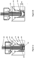
- Figures 1a-1g show removable inserts 100 alone ( Fig. 1d ) or in place within a well 110, e.g., a single well of a multiwell plate.
- the insert may define media perfusion channels 120 to facilitate perfusion 130 of media over a three-dimensional cell sample, e.g., tissue 140 disposed in the well.
- the channels may comprise multiple passages formed within the body of the insert itself, or more preferably, comprise passages defined between the inner surface of the well and outer surface of the insert.
- the perfusion channels may include a check valve which functions to limit backflow of media from the channels to the sample on the upward stroke of the plunger.
- the insert may also include a sample nesting site 150 to receive a sample prior to insertion of the insert into the well.
- the sample nesting site in some embodiments, is disposed in the well itself, e.g., in a depression or sump independent of the insert.
- the insert or the body of the well itself defines a bore 150 which interfits with a plunger 160.
- the plunger 160, well 110, and bore 150 are configured and dimensioned to fit together preferably so that insertion and reciprocation of the plunger into the well permits agitating and mixing of the medium.
- the plunger and the bore fit together to induce perfusion as the plunger moves downwardly or upwardly and medium perfuses the sample and passes through the perfusion channels.
- the plunger also may be configured to introduce one or more sensors 180 for monitoring the presence or concentration of one or more analytes in medium disposed in the well.
- Information from the sensors 180 may be transmitted through a fiber-optic probe 182 disposed in the plunger 170.
- a compound delivery structure 185 may be disposed above the well, enabling the introduction through, e.g., delivery ports, into the well of a biologically active substance or a gas into media surrounding the three-dimensional sample.
- the bottom surface of the well 110 may define a depression that acts as a sump during use.
- the depression may be used to orient and control the positioning of samples in the well and its bottom surface to serve as a sample nesting site 150.
- the well may be one of many wells of a multiwell plate, that may be designed to a standard "Society for Biological Screening" SBS footprint having a 6 mm well diameter with the depression at the bottom of the well having a depth of, e.g., 0.5 mm and a diameter of, e.g., 3 mm.
- the dimensions of the depression may be selected in view of the analysis to be performed in the well. For example, the volume should be sufficient to hold a sample.
- the exemplary dimensions indicated above are suitable for holding a sample that is approximately 300 ⁇ m thick. Other dimensions may be provided, depending on analytical needs.
- the removable insert 100 may be generally cylindrical, and sized and configured to slide into the well with a slight interference fit to its interior wall. See Figure 1d .
- the insert may have a height hi of about 0.2 inches and an outer diameter OD of about 0.247 inches.
- the height of the insert may be selected such that that the stroke distance defined by the length of the bore in which the plunger generates hydrostatic pressure, i.e., perfusion stroke 190, may be increased or decreased to control the perfusion volume.
- the outer diameter of the insert may be selected to allow the insert to fit snugly in the well.
- protrusions 195 may be disposed on the outer sidewall of the insert to help secure and center the insert in the well, providing an outer diameter OD' at some points of 0.251 inches.
- the top edge of the insert may be thin, e.g., have a thickness t1 of 0.002 inches, so as to aid in guiding the plunger into the insert.
- the inner surface of the insert may have an upper tapered portion and a lower vertical portion defining a bore having a diameter d1 of, e.g., 0.15 inches.
- the upper tapered portion may define an opening having a diameter d2 of e.g., 0.1 inches.
- the bottom of the bore of the insert may define an opening having a diameter d3 of, e.g., 0.080 inches.
- the opening may include a media permeable platform, e.g., a screen, sized and located to support a scaffold holding a three-dimensional cell culture or tissue sample.
- the insert defines a plurality of perfusion channels 120 that begin on the bottom of the insert and extend up the insert's outer diameter wall to form a channel such that fluid pumped through the opening having a diameter d3 during the downward stroke of the plunger can be exhausted to create perfusion across a sample.
- Each perfusion channel may have a height h2 of, e.g., 0.004 inches.
- One currently preferred set of dimensions would define a 3 mm plunger stroke within a 3 mm bore so that the displaced volume of the pump (a bit over 20 mm3 or 20 ⁇ l) is approximately 4 times the volume of the channels.
- the plunger and insert are sized such that the plunger moves at least 20 ⁇ l of media when inserted into the bore.
- the snug fit of the insert 100 in the well 110 enables the insert to be held securely in place and, in use, may immobilize and orient the sample 140 in a sample nesting site 150 disposed in a small microchamber or sump formed by the interface created by the depression at the bottom of the well and a bottom portion of the insert.
- the sump is in fluid communication with the perfusion channel 120, i.e., with the media channel, through which perfusion flow 130 takes place.
- the media channel may lead to a drain for collection of spent media.
- media may be moved by the media channel to a waste site rather than back into the well.
- the sample nesting site 150 is disposed on the insert 100 itself.
- the insert may comprise a screen 190 at the bottom of the bore 160, on which a tissue sample or scaffold 200 with cells may be placed.
- the sample nesting site may be disposed on the plunger, e.g., rigidly suspended from its bottom surface, such that the sample nesting site moves together with the plunger to expose the sample to different regions of media. Accordingly a possible but not preferred configuration includes the suspension of the sample nesting site on the plunger.
- Media channels that may be defined by the insert permits media displaced by the plunger to leave the proximity of the sample, e.g., by flowing up the perimeter walls through the annulus defined by an outer surface of the insert and an inner sidewall of the well.
- the media channel may extend from a bottom portion of the insert to a higher portion of the insert.
- the media channel may include a plurality, e.g., four, perfusion channels 120 defined in a bottom portion of the insert 100.
- the perfusion channels may be indentations defined on a bottom surface of the insert.
- perfusion channels may be cylindrical openings defined in the bottom portion of the insert.
- Each of the media channels may define a fluid path that returns media perfused about the sample back to media disposed in the well, or alternatively to a waste reservoir.
- the media channels are in fluid communication with the sample nesting site, permitting flow of media therethrough. The flow of media is impelled by the plunger 170, thereby permitting exposure of the sample to fresh media as the plunger moves.
- the insert may include the sample nesting site 150.
- the insert may include a media permeable platform, such as a screen 190, spanning the opening in a bottom surface of the insert.
- the screen may be made from any number of materials, such as polymers such as polyethylene terephthalate (PET) or polystyrene, cellulose, paper, etc., and attached by ultrasonic welding, heat staking, adhesives or mechanical entrapment.
- PET polyethylene terephthalate
- adhesion of the sample to the nesting site may be enhanced by using attachment promoters or tissue adhesives, such as MatriGelTM or Cell-TakTM.
- the sample nesting site may be within the depression at the bottom of the well.
- Each of the media channels may include a fluid path defining a closed loop beneath the surface of media in the well, permitting media perfusive flow about the sample on both upward and downward movement of the plunger within the bore.
- the insert may be fabricated by injection molding.
- Surface wettability may be increased by treatments known per se, e.g., performing a plasma pretreatment of the inserts to eliminate entrapment of gas bubbles in the perfusion channels by creating a more hydrophilic surface.
- the bore preferably is situated above the nesting site, guides the plunger vertically down into the insert within the sample media disposed in the well, and creates hydrostatic pressure and media movement about the sample.
- the plunger may be adapted for reciprocating movement within the bore disposed in the well, e.g., the bore defined by the insert.
- Figure 1a illustrates a plunger 170 extended into the bore 160, in close proximity to the sample, while Figure 1b illustrates the plunger 170 somewhat retracted.
- a volume of media is forced via hydrostatic pressure across the tissue or scaffold and up (or down) the perimeter walls between the insert and the inner surface of the well.
- Figure 1g shows one form of a check valve 210 for inhibiting backflow of media from the perfusion channels to the sample on upstroke of the plunger.
- the optional check valve 210 takes the form of a free floating annular ring comprising, e.g., an elastomeric polymer, that fits over the annular opening of the channels within the body of culture medium.
- hydrostatic pressure from the channels displaces the ring and permits flow of spent media upwardly and radially inwardly to mix back into the volume of media in the well.
- suction holds the ring in substantial sealing engagement with the opening of the channels, inhibiting media backflow from the channel.
- Medium accordingly is drawn down around the plunger through the annular clearance space between the plunger and the bore.
- check valve arrangements are contemplated, and the check valve function may be omitted if some backflow of media is tolerable.
- Still another alternative to a check valve for inhibiting back flow is to dispense with recirculation of spent medium, and to design the perfusion channels for one way drainage into a reservoir in the body of the well plate (not shown).
- the sample nesting site may include a scaffold 200 attached to the insert or to the bottom of the sump.
- a scaffold is a three-dimensional porous solid such as a collagen membrane that mimics the parenchyma of tissue and its surrounding structure in vivo.
- Such scaffolds are available commercially and may be fabricated from gels or fibrous/porous media, e.g., Alvetex®Scaffold or 3D BioTek scaffold material.
- Alvetex®Scaffold is a highly porous, cross-linked polystyrene scaffold that has been section into 200 ⁇ m thick membrane. The resulting material is inert and does not degrade during normal use. It has been adapted to fit a variety of conventional cell culture plastic-ware formats.
- Alvetex®Scaffold provides a suitable 3D structure in which cells can proliferate, migrate, differentiate, and function in an appropriate niche environment. Cells maintain a 3D shape and form close interactions with adjacent cells.
- beads 220 comprising specific binders to biomolecules of interest may be disposed in the well 110 beneath or adjacent the sample as a means to assist with sample analysis.
- the scaffold 200 or tissue may be immobilized to the insert so that media can perfuse through and around it.
- the media contains, for example, key nutrients, signaling molecules, drugs, etc.
- Beads such as are available from Luminex® containing an attachment molecule may be placed at the bottom of the well, such that multiple signaling molecules may be captured and subsequently detected or quantitated.
- One may take advantage of the sump and small volume of media in intimate contact with the sample effectively to amplify the concentration of the signaling molecules and to capture them on the beads.
- the beads preferably stay at the bottom of the well because they are trapped between the scaffold and the small channels around the perimeter.
- the insert or array of inserts may be removed, and the beads can be read using known techniques, e.g., analyzed in a flow cytometer.
- the apparatus preferably includes sensors 180, in addition to the optional beads described above, e.g., disposed on the plungers, for detecting the concentration of solutes in media disposed about the sample.
- the sensors may measure the concentration of dissolved oxygen, carbon dioxide, or hydrogen ions in media about the sample. Measurements spaced in time permit assessment of the health or metabolic efficiency of the sample under various condition of its microenvironment.
- sensors 180 may be placed at the bottom of a well or the sump to detect the concentration of solutes in the media
- one may dispose an O 2 or a pH sensor in the space between the bottom of the insert 100 and the bottom of the well 110.
- Plates with sensors are commercially available, but the drawback is that one has to grow the cells on the sensor.
- Kits with water soluble sensors to put into the media are also available, but also present disadvantages.
- the embodiment described herein allows microwell plates to be provided with sensors on the bottom and an insert thereabove, allowing the microwell plate to be read in a standard plate reader, e.g., the BioTek Synergy line of plate readers.
- These types of sensor configuration may be used with scaffolds or two-or three dimensional cultures grown on a membrane.
- sensors may be utilized with the apparatus depending on the analysis to be performed and its selected configuration, including oxygen sensors, such as oxygen-quenched fluorescent sensors, pH sensors, including fluorescent sensors, ISFET and impedance sensors, CO 2 sensors, including bicarbonate buffer coupled and ammonium dye coupled fluorescent sensors as well as other CO 2 sensors; various ion and small molecule sensors; large molecule sensors including surface plasmon resonance sensors and sensors exploiting the principle of Wood's anomaly; acoustic sensors; and microwave sensors.
- oxygen sensors such as oxygen-quenched fluorescent sensors, pH sensors, including fluorescent sensors, ISFET and impedance sensors
- CO 2 sensors including bicarbonate buffer coupled and ammonium dye coupled fluorescent sensors as well as other CO 2 sensors
- various ion and small molecule sensors large molecule sensors including surface plasmon resonance sensors and sensors exploiting the principle of Wood's anomaly
- acoustic sensors and microwave sensors.
- a conventional plate reader may be used.
- Preferred sensors are fluorophores. Many fluorescent sensing compounds and preparations are described in the art and many are available commercially from, for example, Molecular Probes Inc. and Frontier Scientific, Inc.
- the currently preferred oxygen sensor is a fluorophore with the signal inversely proportional to oxygen concentration such as a porphyrin or rhodamine compounds immobilized as a particle or homogenously distributed in an oxygen permeable polymer, e.g., silicone rubber.
- the currently preferred compound is porphyrin.
- the currently preferred pH sensor is a fluorescent indicator dye, fluorescein, whose signal decreases upon protonation of the dye, and which is either entrapped in a particle that is suspended in a carrier polymer, or covalently attached to a hydrophilic polymer.
- Useful fluorescent CO 2 indicator sensor typically are based on a pH sensitive transducer, with the fluorescence being indirectly modulated by the production of carbonic acid due to reaction of carbon dioxide with water. See , e.g., O.S.Wolfbeis, Anal. Chem. 2002, 74, 2663-2678 .
- a fluorophore that detects glucose also can be used, such as one based on a non-enzymatic transduction using a boronic probe that complexes with glucose, resulting in a charge transfer that modulates the fluorescence of the probe, or an enzymatic glucose transducer that couples a glucose oxidase to a fluorescent oxygen sensor, with the binding and oxidation of glucose resulting in a quantitative modulation of the oxygen sensor. It also is within the scope of embodiments of the invention to employ a fluorophore or other type of sensor sensitive to biological molecules such as, for example, lactate, ammonia, or urea.
- a lactate sensor can be based on an enzymatic sensor configuration, with lactate oxidase coupled to a fluorescent oxygen sensor, and with the binding and oxidation of lactate resulting in a quantitative modulation of the oxygen sensor.
- An ammonia or ammonium ion sensor can be configured with immobilization of a protonated pH indicator in a hydrophobic, gas permeable polymer, with the fluorescence output quantitatively modulated by reaction with transient ammonia.
- a urea sensor can be based on an enzymatic sensor configuration, with urease coupled to a fluorescent ammonia transducer, and with the binding and reduction of urea to ammonia, resulting in modulation of the ammonia sensor fluorescence. The nature of the sensor generally does not form an aspect of embodiments of this invention.
- the insert guides the plunger to provide perfusion by creating hydrostatic pressure in the column of medium above the tissue sample in the insert and/or in the depression at the bottom of the well.
- medium is forced to flow across and sometimes through the tissue and exits the chamber through a series of channels around the perimeter of the insert and upwardly between the outer surface of the insert and the inner wall of the well.
- By moving the plunger up and down medium is moved across the tissue, replenishing nutrients, providing oxygen, and sweeping away wastes. Accordingly, the microenvironment around the sample may be continuously perfused between measurements.
- the plunger moves into the bottom position, resting on or just above the insert, its motion is stopped, the small transient volume is created, and measurements are made. Efficiency of perfusion through the insert may be increased by altering the stroke height, speed and clearances between the plunger and the insert.
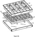
- a well plate configuration suitable for receiving the inserts described above and practicing embodiments of the invention comprises a wellplate 400 defining a plurality of wells 110.
- the wellplate may be combined with a cartridge 410 and removable cover 420.
- multiwell plate 400 has 24 wells.
- the number of wells 110 in a plate may vary from 1 to several thousand. In some embodiments, a single well of nearly any size may be fabricated, or multiple wells may be fabricated, or multiple wells may be fabricated in a one- or two-dimensional arrangement.
- the cartridge 410 is a generally planar element comprising a frame 430 made, e.g., from molded plastics.
- Planar surface 440 defines a plurality of regions 450 that correspond to, i.e., register with, a number of the respective openings of a plurality of wells 110 defined in the multiwell plate 400.
- the planar element defines first, second, third, and fourth ports 460, which serve as reservoirs for delivery of gases or reagents, and a central aperture 470 to a plunger 170.
- Each of the ports is adapted to hold and to release on demand a test fluid to the respective well 110 beneath it.
- the ports 460 and plungers 170 may be compliantly mounted relative to the microplate 400 so as to permit it to nest within the microplate by accommodating lateral movement.
- the construction of the microplate to include compliant regions permits its manufacture to looser tolerances, and permits the cartridge to be used with slightly differently dimensioned microplates. Compliance can be achieved, for example, by using an elastomeric polymer to form planar element 440, so as to permit relative movement between frame 430 and the plungers and ports in each region.
- Each of the ports 460 may have a cylindrical, conic or cubic shape, open through planar element 430 at the top, and closed at the bottom except for a small hole, i.e., a capillary aperture, typically centered within the bottom surface.
- the capillary aperture is adapted to retain test fluid in the port, e.g., by surface tension, absent an external force, such as a positive pressure differential force, a negative pressure differential force, or possibly a centrifugal force.
- Each port may be fabricated from a polymer material that is impervious to gasses, test compounds, or from any other solid material. When configured for use with a multiwell microplate 400, the liquid volume contained by each port may range from 500 ⁇ l to as little as 2 ⁇ l, although volumes outside this range are contemplated.
- a submersible plunger 170 i.e., sensor sleeve or barrier
- Plunger 170 may have one or more sensors 180 disposed on a lower surface thereof for insertion into media in a well 110.
- the sensor can be used to detect the concentration of a dissolved media component in media about the sample nesting site.
- a sensor for this purpose is a fluorescent indicator, such as an oxygen-quenched fluorophore, embedded in an oxygen permeable substance, such as silicone rubber.
- the fluorophore has fluorescent properties dependent on the presence and/or concentration of a constituent in the well 110.
- Other types of known sensors may be used as described above, such as electrochemical sensors, Clark electrodes, etc.
- Plunger 170 may define an aperture and an internal volume adapted to receive a sensor.
- the cartridge 410 may be attached to the plunger, or may be located proximal to the plunger without attachment, to allow independent movement.
- the cartridge 410 may include an array of compound storage and delivery ports assembled into a single unit and associated with a similar array of plungers.
- the apparatus may also feature a removable cover 420 for the cartridge 110 or for multiwell plate 400.
- the configuration of cartridge 110 as a cover for multiwell plate 400 may help prevent evaporation or contamination of a sample or media disposed in wells 110.
- the cover 420 may also be configured to fit over the cartridge 110 thereby to reduce possible contamination, to maintain the content of the gas in the wells, or reduce evaporation of fluids disposed in the ports 460 of the cartridge 410.
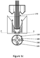
- Figure 5 depicts a schematic cross section of a well 110 of an embodiment of the invention showing structure 185 used to add drugs or gasses to wells so as to alter the microenvironment of the samples under examination. Details of the delivery system of the existing, commercially available Seahorse XF Analyzer are described in US 20080014571 , the disclosure of which is incorporated herein by reference.
- the drug delivery manifold 510 may be modified to deliver environmental gases, e.g., an external gas 520, i.e., from a gas cylinder, or internal air 530 to the head space directly above each well.
- the internal air may be, e.g., ambient air from inside the instrument that is compressed via a small internal compressor, to pressurize the drug ports to deliver drug compounds.
- the delivery of gas to the head space may allow manipulation of the environment around the test sample to create conditions simulating hypoxia ( ⁇ 5% O 2 ) or normoxia and/or low pH.
- a source of oxygen, carbon dioxide, and/or a biologically inert gas may be injected into media in the well or a headspace above the surface of media in the wells for controlling the composition of gas in the headspace or in the media.
- the gas may be injected into the media or headspace from ports 460.
- a cartridge 410 contains a set of 4 ports 460 that may be used to deliver various compounds to the sample within the wellplate.
- a common test performed on the XF instrument is a mitochondrial stress test.
- a series of injections are delivered through the drug ports of the cartridge in order to measure the response of the biological sample to various compounds (oligomycin, FCCP, rotenone and antimycin). These compounds are preloaded into a drug reservoir (port) on the XF cartridge prior to execution of the assay.
- a manifold When the cartridge is inserted into the instrument it is coupled to a manifold which when activated by a solenoid valve, provides pneumatic pressure to the head space of the reservoir forcing the compound through a small orifice and into the well containing the biological sample.
- the pneumatic manifold and valve system may be modified to redirect one of these ports to an external gas supply (gas cylinder or bottle).
- the gas supply may be connected to the instrument through a port on the rear connector panel.
- the bottle may be located near the instrument and may contain a regulator and bubbler for humidification of the incoming gas.
- a solenoid valve When activated, a solenoid valve may open, allowing the gas to flow through the manifold/cartridge interface, through the drug port orifice, and into the head space above the biological sample.
- the gas By oscillating the plunger (probe) vertically, the gas will be mixed with the medium allowing control of the available oxygen to the sample. For example, by perfusing argon into the head space, the available O 2 in the medium is displaced and a more hypoxic condition is created around the sample. By turning off the gas and mixing, ambient levels of O 2 may be re-established.
- a source of a solution of a biologically active substance may be in fluid communication with media in wells for exposing a sample to the substance
- the instrument software may be modified to facilitate control of the valve/timing and to expose some of the calculation variables used during calibration.
- the concentration at calibration is preferably known and input into the calculation table.
- the initial calibration value F or current ambient concentration
- calibration and solution of equation (1) may be achieved by injecting sodium sulfite into a set of control wells and calibrating the system based on a known F0 value.
- certain coefficients may be made accessible in the software. A separate window may be created in the software to facilitate access to these variables, valve control and calculation of calibration coefficients.
- the instrument may be tested using a well characterized cell line (mouse C2C12) to verify proper operation and control of the gas system.
- a series of tests may be conducted to demonstrate the ability to purge O 2 from medium and create a hypoxic microenvironment around the sample. These tests may include:
- An alternative to controlling O 2 and pH within the sample environment may be to enclose the entire instrument in an environmental chamber and pump down the chamber to the desired levels.
- This alternative approach may be less desirable, as it may be very costly, take up a lot of lab space, and require long periods of time to achieve the desired levels around the tissue. By the time these O 2 levels are achieved the tissue may be dead.
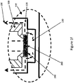
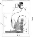
- Figure 6 shows a schematic of an analyzer used in connection with embodiments of the invention. It comprises an apparatus 600 including a compound storage and delivery apparatus 610 disposed in a housing 615(shown in dashed lines) and includes a cartridge 410 defining a plurality of apertures for receiving sensor structures and a plurality of fluid ports (shown in detail in Figs. 4a and 4b ) compliantly mounted, and a stage or base 130 adapted to receive a multiwell plate 400, e.g., a cell culture plate.
- the cartridge 410 is disposed above, and adapted to mate with, the multiwell plate 400.
- the cartridge 410 optionally is held by a cartridge holder 630 adapted to receive the cartridge 410.
- the apparatus also includes a mounting block 640, which can reciprocate as shown by the double headed arrow, preferably powered by a motor (not shown), including an elevator mechanism 650.
- the elevator mechanism 650 may be adapted to move the cartridge 410 relative to the stage 620, or well plate 400.
- the mounting block includes a gas multiplexer 660 attached to a gas supply or gas reservoir 670.
- the gas supply 670 is in fluid communication with the cartridge, and is used to impel the delivery of test fluid from a port in the cartridge to a well in the multiwell plate 400, or to fix the gas composition in one or more wells.
- a plurality of probes or plungers 170 with sensors are adapted for insertion into the plurality of apertures in the cartridge 410, and may be used to gather data indicative of the state of cells disposed in wells in the multiwell plate 400.
- the compound storage and delivery apparatus 610 is controlled by a controller 680, that may be integrated with a computer 690, that may control the elevator mechanism, the multiplexer, and the pressure source.
- the controller 680 may, thereby, permit delivery of a test fluid from a port to a corresponding well when an associated sensor is disposed in the well.
- the apparatus described herein is a modification of the apparatus disclosed in US 20080014571 , referenced above, and enables experimentation with and analysis of three-dimensional cell culture samples, such as a tissue sample, a biopsied sample, or a cell scaffold holding cells. Viability of the sample may be maintained and control exercised over its microenvironment.
- a gas may be added to the media or to a headspace in the well above the media to modify the microenvironment about the sample by altering dissolved gas composition.
- a solution of a biologically active substance may be added to the media to modify the microenvironment about the sample by exposing the sample to a biologically active substance.
- a metered amount of one or more gases and/or one or more drugs or other solutes may be added to media in the well to set the microenvironment in the medium about the sample to a predetermined point.
- the microenvironment in the well may be set to a hypoxic condition.
- the concentration of one or more solutes in media about the sample may be measured.
- a plurality of measurements, separated in time, of the concentration of one or more solutes in media about the sample may be taken.
- the method includes adding an oxygen scavenger such as sodium sulfite to the medium.
- a human biopsied tissue sample may be placed on the nesting site, potential therapeutic drugs may be added to the media, and the effect of the drugs on the sample may be assessed.
- Example 1 Development of a custom injection molded wellplate and perfusion insert designed for tissue perfusion and immobilization.
- the Seahorse XF96 flux analyzer was developed and optimized to measure bio-energetic activity in cell based assays.
- XF measurements are based on a patented method in which a small, temporary measurement volume is created around a monolayer of cells which are adherent to the bottom of the wellplate. A small volume is created when the plunger (probe) is lowered to the bottom of the well (3.8 mm diameter) and engages a set of standoffs (0.20 mm height) to create a volume of approximately 2.25 microliters.
- the present design of the wellplate is not optimal for use with tissue samples because: (1) samples need to be immobilized and orientated to prevent them from shifting between measurements, (2) lack of a consistent and homogeneous supply of nutrients (perfusion) of the three-dimensional samples, and (3) a larger measurement chamber is required that will accommodate samples up to 200 micrometers thick.
- a disposable 96-well plate and plunger (probe) system to work within the Seahorse XF96 instrument that immobilizes, orientates, and provides perfusion of tissue samples.
- the custom wellplate and perfusion inserts described above are suitable for use with tissue samples.
- the wellplate may be designed to a standard "Society for Biological Screening" SBS footprint having a 6 mm well diameter with a depression at the bottom of the well 0.5 mm deep, 3 mm diameter, used to orient and control the positioning of samples in the depression at the bottom of the well.
- the perfusion inserts are designed to slide into the well, with a slight interference to the wall so that the insert is held in place over the sample, and to immobilized the sample in the depression at the bottom of the well.
- a wellplate, inserts, and plungers may be assembled and installed in a specialized heatsink that provides alignment and thermal control of the samples.
- Appropriate position offsets and a calibration protocol for the sensors may be developed.
- the calibration protocol consists of determining the appropriate volumes, diffusion constants, and sensor gains that are unique to the plate, insert, and probe geometry. These constants may be calculated using calibration reagents titrated to known concentrations to develop a set of coefficients that describe the signal outputs as a function of analyte concentration (O 2 or H + ).
- the optical signals (based on a 16 bit readout) are normalized to a starting H + concentration (pH 7.4) by determining the excitation intensity for each probe that provides a desired starting signal at pH 7.4.
- the signal at different H + concentration is recorded to develop a standard curve.
- the coefficients for the standard curve are then loaded into the instrument so that each sensor is calibrated over a range of concentrations to be measured.
- the Stern Volmer quenching constant may be calculated based on equation 1 below and this relationship used to calculate the O 2 level at each time point during the experiment.
- K 1 / O 2 F 0 / F ⁇ 1
- a series of tests may be conducted to determine the best geometry for the perfusion inserts. These tests may involve taking repeated OCR/ECAR measurements of a standard, well characterized cell line such as C2C12 fibroblasts. After each measurement the plungers (probes) may be oscillated to perfuse the measurement chamber and optimize the timing, Z travel, and speed to get the best perfusion. The best perfusion may be determined based on the ability of the system to restore the measurement chamber to the starting concentration of O 2 and pH.
- the device includes a plurality of cylindrical vessels fitted with a polycarbonate perfusion insert.
- the insert is fitted to the bottom of the vessel to form a pair of chambers within the vessel that are connected through a 1.5 mm port.
- the upper chamber consists of a reservoir of media which is approximately 30 times the volume of the lower chamber.
- the inside diameter of the insert engages the Seahorse sensor cartridge to form a piston-like pump having a stroke length of approximately 5 mm and a diameter of 3 mm.
- the plunger of the Seahorse sensor cartridge when moved through the inner diameter of the insert, forces media from the upper section of the chamber, through the port, into the lower chamber from which it exits through a set of peripheral vents between the inside diameter of the vessel and the outside diameter of the insert.
- a volume of fluid is perfused through the lower chamber such that the fluid turnover is a minimum of 2 times the static volume.
- a depression in the vessel (1 mm x 0.25 mm) where, during use, a spherical micro-tissue is positioned for measurement.
- the cartridge comes to rest on a surface where the sensors are positioned in the center of the port which isolates the top chamber from the bottom chamber.
- the sensors are thus positioned over the micro-tissue, sealing the lower chamber from the upper chamber. Within this reduced volume of fluid, measurements are collected from the sensors to record the oxygen and pH concentrations at various timed intervals. From this data the oxygen and pH flux (dO/dT), (dpH/dT) are determined. This method has been used to evaluate the geometric properties of the insert to optimize fluid turnover while maintaining tissue position and to facilitate measurements of the metabolic properties of the tissues.
- HTC116 colon carcinoma cells grown in 2D mono-layer culture are compared to cells formed in a 3D Spheroid (using the hanging drop method) using a Seahorse Bioscience Mitochondrial Stress Test (MST).
- MST Seahorse Bioscience Mitochondrial Stress Test
- the spheroid image on the right shows a single micro-tissue sitting in the 1 mm x 0.25 mm relief in the bottom of the well (size approximately 200 microns).
- the signatures reveal distinct differences in the spare respiratory capacity between the two culture types (maximum respiration, basal).
- this data may be correlated to a set of glucagon and insulin biomarkers co-located in the in the perfusion path using an in situ ELISA assay to correlate oxygen consumption to insulin and glucagon secretion.
- 3D micro-tissues ranging in size from 50-600 microns have been generated.
- cells are seeded with 40 ⁇ l of media into a commercially available seeding lid provided by InSphero Bioscience (Zurich, Switzerland).
- ECMs extra cellular matrices
- tissue generally consisting of protein matrices that define the micro-environment around the cell.
- spheroids Once the spheroids are formed they are placed into storage plate with an additional 100 ⁇ l of media where they are maintained until ready to use. Using this method, 3D spheroids have been generated from Hep G2's (human liver carcinoma) and HCT 116 (human colorectal carcinoma). These cell lines have been shown to form uniform sized spheroids both as monocultures and co-cultures. In addition, referring to Figure 10 , scaffolded discs containing MCF-7 (breast ductal carcinoma) have been successfully generated.
- spheroids may be used to perform a test for mitochondrial toxicity.
- hepatocytes are co-cultured with non-parenchymal (Kupffer cell, etc.) cells to form a liver micro-tissue that presents a functional immune response.
- the system is used to screen the tissues for toxicity by introducing FCCP and measuring respiratory capacity (FCCP stimulated vs basal OCR).
- FCCP stimulated vs basal OCR introducing FCCP and measuring respiratory capacity
Claims (29)
- Ein Apparat zum Durchführen der Analyse einer dreidimensionalen Zellprobe, wobei der Apparat Folgendes umfasst:Eine Vielzahl von Vertiefungen zum Aufbewahren der entsprechenden Proben und Probenmedien, wobei zumindest eine Vertiefung Folgendes umfasst:eine Probenbeherbergungsstelle, angeordnet darin,darüber angeordnet ein Loch, das so beschaffen ist, dass es mit einem Stempel zusammenpasst, der sich vertikal nach unten innerhalb und relativ zu dem Loch bewegt und innerhalb der Probenmedien, die in der Vertiefung angeordnet sind, undeinen Medien-Kanal in flüssiger Kommunikation mit besagter Probenbeherbungsstelle, welcher den Fluss vom Medium durch ihn hindurch, getrieben durch den Stempel ermöglicht und die Exposition von besagter Probe gegen frisches Medium, so lange sich der Stempel bewegt, ermöglicht.
- Der Apparat von Anspruch 1, wobei sich der Stempel relativ zur Beherbergungsstelle bewegt, um Verteilung von Medium über die Probe zu induzieren.
- Der Apparat von Anspruch 1, wobei sich der Stempel und die Probenbeherbergungsstelle gemeinsam bewegen, um die Probe an verschiedenen Regionen von Medium zu exponieren.
- Der Apparat von Anspruch 1, wobei besagter Medium-Kanal einen flüssigen Pfad umfasst, der Medium zurückführt, welches über die Probe verteilt wurde, zurück zum Medium, das in der Vertiefung angeordnet ist.
- Der Apparat von Anspruch 1, wobei besagtes zumindest eine Loch definiert ist durch einen entfernbaren Vertiefungseinsatz.
- Der Apparat von Anspruch 1, wobei die zumindest eine Probenbeherbergungsstelle und das zumindest eine Loch definiert sind durch einen entfernbaren Vertiefungs-Einsatz.
- Der Apparat von Anspruch 1, wobei besagte Probenbeherbergungsstelle, besagtes Loch und besagter Medien-Kanal definiert sind durch einen entfernbaren Vertiefungs-Einsatz.
- Der Apparat von Anspruch 1, wobei besagte Probenbeherbergungsstelle eine Medium-durchlässige Plattform umfasst, definiert durch einen entfernbaren Vertiefungs-Einsatz.
- Der Apparat von Anspruch 1, wobei die Vertiefung einen Sammelbehälter in flüssiger Kommunikation mit dem Medium-Kanal enthält.
- Der Apparat von Anspruch 1, wobei die Probenbeherbergungsstelle angeordnet ist innerhalb eines Sammelbehälters zum Sammeln von Medium und in flüssiger Kommunikation mit besagtem Medium-Kanal.
- Der Apparat von Anspruch 1, wobei besagter Medium-Kanal einen flüssigen Pfad umfasst, der eine geschlossene Schleife unterhalb der Oberfläche des Mediums in der Vertiefung definiert und einen Mediumzufluss über besagte Probe sowohl bei der Aufwärts- als auch bei der Abwärtsbewegung eines Stempels innerhalb des Loches ermöglicht.
- Der Apparat von Anspruch 1, desweiteren umfassend einen Sensor zum Nachweis der Konzentration einer gelösten Substanz im Medium, angeordnet über besagter Probe.
- Der Apparat von Anspruch 12, wobei der Sensor am Boden der Vertiefung angeordnet ist.
- Der Apparat von Anspruch 1, desweiteren umfassend einen Stempel, angepasst zur reziprogen Bewegung innerhalb der Löcher der entsprechenden Vertiefungen.
- Der Apparat von Anspruch 14, desweiteren umfassend Sensoren, angeordnet auf dem Stempel zum Nachweisen der Konzentration der gelösten Substanzen in Medien, angeordnet relativ zur besagten Probe.
- Der Apparat von Anspruch 12 oder 15, wobei besagte Sensoren die Konzentration von Sauerstoff, Kohlendioxid oder Wasserstoff-Ionen, gelöst in den Medien über besagter Probe messen.
- Der Apparat von Anspruch 1, wobei die Vielzahl von Vertiefungen eine Vielvertiefungsplatte mit 24 oder 96 Vertiefungen definiert.
- Der Apparat von Anspruch 1, desweiteren umfassend eine Quelle für Sauerstoff, Kohlendioxid und/oder ein biologisch inertes Gas in flüssiger Kombination mit dem Medium in einer Vertiefung oder einer Gaskammer oberhalb der Oberfläche des Mediums in den Vertiefungen zum Steuern der Zusammensetzung des Gases in dem Gasraum oder in dem Medium.
- Der Apparat von Anspruch 1, desweiteren umfassend eine Quelle einer Lösung einer biologisch aktiven Substanz in flüssiger Kommunikation mit dem Medium in Vertiefungen, um eine Probe gegen besagte Substanz zu exponieren.
- Der Apparat von Anspruch 1, desweiteren umfassend ein dreidimensionales Zellwachstumsgerüst, angeordnet auf besagter Probenbeherbergungsstelle.
- Ein Apparat zum Durchführen der Analyse von dreidimensionalen Zellproben, wobei der Apparat Folgendes umfasst:eine Vertiefung zur Aufbewahrung einer Probe und Probenmedium, umfassend eine Probenbeherbergungsstelle,angeordnet oberhalb besagter Probenbbeherbergungsstelle, eine Bohrung, die so definiert ist, dass sie mit einem Stempel zusammenpasst, der sich vertikal nach unten bewegt innerhalb der Bohrung und innerhalb des Mediums, angeordnet in besagter Vertiefung,einen Medium-Kanal in flüssiger Kombination mit besagter Probenbeherbergungsstelle, welche die Medienverteilung für besagte Probe ermöglicht undein Stempel, angepasst zur reziproken Bewegung in besagter Bohrung, um dadurch die Medienverteilung über besagte Probe zu führen.
- Der Apparat von Anspruch 21, desweiteren umfassend einen Sensor zum Nachweisen der Konzentration einer gelösten Medium-Komponente im Medium über der Probenbeherbergungsstelle.
- Ein Einschub für eine Vertiefung einer Kultur-Platte zum Anpassen der Vertiefung in der implementierten Verteilung einer dreidimensionalen Zellkulturprobe, die dort angeordnet ist, wobei der Einschub eine Struktur umfasst, die Folgendes definiert:eine Probenbeherbergungsstelle, umfassend eine Medien-durchlässige Plattform,
oberhalb davon angeordnet eine Bohrung, die so dimensioniert ist, dass sie zusammenpasst mit einem Stempel, der sich vertikal nach unten innerhalb der Bohrung bewegt und innerhalb von Medium, angeordnet in einer Vertiefung, sowieeinen Medium-Kanal in flüssiger Kommunikation mit besagter Probenbeherberungsstelle, welcher die Mediumverteilung über besagter Probe, verteilt durch einen Stempel, ermöglicht. - Ein Verfahren zum Experimentieren mit einer dreidimensionalen Zellkulturprobe, wie zum Beispiel einer Gewebsprobe, einer Biopsie-Probe oder einem Zellgerüst, welches Zellen beherbergt, um die Lebensfähigkeit der Probe beizubehalten, und die Kontrolle über deren Mikroumgebung auszuüben, wobei das Verfahren folgende Schritte umfasst:Bereitstellen einer Vertiefung, enthaltend eine Probenbeherbergungsstelle, eine Bohrung, die so dimensioniert ist, um mit einem Stempel zusammenzupassen, der oberhalb der Probenbeherbergungsstelle angeordnet ist, einem Medien-Kanal in flüssiger Kommunikation mit besagter Probenbeherbergungsstelle und einen Stempel, angepasst zur reziproken Bewegung in besagter Bohrung;Platzieren einer Probe auf der Probenbeherbergungsstelle in dem Medium innerhalb der Probe undBewegen von besagtem Stempel innerhalb der Bohrung, um den Medienfluss über die Probe auszuüben bzw. durch besagten Kanal und dabei die Probe mit dem Medium zu versorgen.
- Das Verfahren von Anspruch 24, umfassend den weiteren Schritt der Zugabe eines Gases zu dem Medium oder zu dem Vorratsbehälter in der Vertiefung oberhalb des Mediums, um die Mikroumgebung über der Probe durch Verändern der Zusammensetzung des gelösten Gases zu modifizieren.
- Das Verfahren von Anspruch 24, umfassend den weiteren Schritt der Zugabe einer Lösung einer biologisch aktiven Substanz zu dem Medium, um die Mikroumgebung über der Probe zu modifizieren durch Exponieren der Probe gegen die biologisch aktive Substanz.
- Das Verfahren von Anspruch 24, umfassend den weiteren Schritt des Messens der Konzentration von einer oder mehreren gelösten Substanzen in den Medien über besagter Probe.
- Das Verfahren von Anspruch 24, umfassend den weiteren Schritt des Herstellens einer Vielzahl von Messungen, getrennt hinsichtlich der Zeit der Konzentration von einer oder mehreren gelösten Substanzen in den Medien über besagter Probe.
- Das Verfahren von Anspruch 24, umfassend den weiteren Schritt des Zuführens einer abgemessenen Menge von einem oder mehreren Gasen und/oder ein oder mehreren gelösten Stoffen zu dem Medium in besagter Vertiefung, um dadurch die Mikroumgebung in dem Medium über besagter Probe auf einem vorherbestimmten Punkt einzustellen.
Applications Claiming Priority (2)
| Application Number | Priority Date | Filing Date | Title |
|---|---|---|---|
| US201261725781P | 2012-11-13 | 2012-11-13 | |
| PCT/US2013/069839 WO2014078379A2 (en) | 2012-11-13 | 2013-11-13 | Apparatus and methods for three-dimensional tissue measurements based on controlled media flow |
Publications (2)
| Publication Number | Publication Date |
|---|---|
| EP2920292A2 EP2920292A2 (de) | 2015-09-23 |
| EP2920292B1 true EP2920292B1 (de) | 2017-01-11 |
Family
ID=50069276
Family Applications (1)
| Application Number | Title | Priority Date | Filing Date |
|---|---|---|---|
| EP13827054.1A Active EP2920292B1 (de) | 2012-11-13 | 2013-11-13 | Vorrichtung und verfahren für dreidimensionale gewebemessungen auf basis eines kontrollierten medienstroms |
Country Status (5)
| Country | Link |
|---|---|
| US (1) | US9494577B2 (de) |
| EP (1) | EP2920292B1 (de) |
| JP (1) | JP6326058B2 (de) |
| CN (1) | CN104471052B (de) |
| WO (1) | WO2014078379A2 (de) |
Families Citing this family (34)
| Publication number | Priority date | Publication date | Assignee | Title |
|---|---|---|---|---|
| RU2505813C1 (ru) | 2012-11-06 | 2014-01-27 | Виктор Вениаминович Тец | Способ определения чувствительности микроорганизмов к антимикробным веществам |
| US9790465B2 (en) | 2013-04-30 | 2017-10-17 | Corning Incorporated | Spheroid cell culture well article and methods thereof |
| US20150050735A1 (en) * | 2013-08-14 | 2015-02-19 | 3-D Matrix, Ltd. | Well plates |
| EP3075840B1 (de) * | 2013-11-28 | 2018-10-17 | Viktor Veniaminovich Tets | Verfahren zur bestimmung der empfindlichkeit von mikroorganismen gegenüber antimikrobiellen wirkstoffen |
| SG11201703493SA (en) | 2014-10-29 | 2017-05-30 | Corning Inc | Cell culture insert |
| JP6930914B2 (ja) | 2014-10-29 | 2021-09-01 | コーニング インコーポレイテッド | 灌流バイオリアクタ・プラットフォーム |
| US11008542B2 (en) * | 2015-02-04 | 2021-05-18 | Cytiva Sweden Ab | Aseptically connectable sensor patch |
| JP6855382B2 (ja) * | 2015-03-26 | 2021-04-14 | ユニバーシティー オブ ヒューストン システム | 細胞の統合された機能性および分子のプロファイリング |
| RU2604789C1 (ru) | 2015-06-23 | 2016-12-10 | Виктор Вениаминович Тец | Питательная среда для выращивания бактерий |
| WO2017153992A1 (en) | 2016-03-08 | 2017-09-14 | Yissum Research Development Company Of The Hebrew University Of Jerusalem Ltd | Method and system for continuous biosensing |
| CA3043708A1 (en) * | 2016-11-17 | 2018-05-24 | Cleveland State University | Chip platforms for microarray 3d bioprinting |
| US10883978B2 (en) | 2017-01-31 | 2021-01-05 | Agilent Technologies, Inc. | Method and device for calibration of biological flux |
| US11639925B2 (en) * | 2017-04-06 | 2023-05-02 | Agilent Technologies, Inc. | Method and apparatus for measuring physiological properties of biological samples |
| DE102017108022B4 (de) * | 2017-04-13 | 2019-01-17 | Universität Rostock | Messbox zur Analyse von Substanzen |
| WO2019014610A1 (en) | 2017-07-14 | 2019-01-17 | Corning Incorporated | CELL CULTURE CONTAINER FOR 3D CULTURE AND METHODS OF CULTURING 3D CELLS |
| CN111065729B (zh) | 2017-07-14 | 2024-04-26 | 康宁股份有限公司 | 细胞培养容器 |
| JP7245222B2 (ja) | 2017-07-14 | 2023-03-23 | コーニング インコーポレイテッド | 手動又は自動で培地を交換するための3d細胞培養容器 |
| US11857970B2 (en) | 2017-07-14 | 2024-01-02 | Corning Incorporated | Cell culture vessel |
| US11262349B2 (en) | 2017-10-11 | 2022-03-01 | Cleveland State University | Multiplexed immune cell assays on a micropillar/microwell chip platform |
| EP3697889A4 (de) * | 2017-10-19 | 2021-07-14 | University of Pittsburgh - of The Commonwealth System of Higher Education | Mehrachsige mechanische stimulationssysteme und inkubatoren |
| WO2019142913A1 (ja) * | 2018-01-18 | 2019-07-25 | 国立大学法人東京大学 | 3次元組織内のグルコース濃度マッピングのための蛍光マイクロ粒子 |
| CN111065725B (zh) | 2018-07-13 | 2024-03-29 | 康宁股份有限公司 | 包括具有互联的壁的微板的流体装置 |
| WO2020013845A1 (en) | 2018-07-13 | 2020-01-16 | Corning Incorporated | Cell culture vessels with stabilizer devices |
| JP7171695B2 (ja) | 2018-07-13 | 2022-11-15 | コーニング インコーポレイテッド | 液体培地送達面を含む側壁を有するマイクロキャビティ皿 |
| EP3850336A4 (de) | 2018-09-14 | 2022-02-09 | Illumina, Inc. | Durchflusszellen und zugehörige verfahren |
| CN110961167B (zh) * | 2018-09-29 | 2022-04-01 | 中国科学院微电子研究所 | 一种微流道网络芯片 |
| US11591562B2 (en) * | 2018-12-18 | 2023-02-28 | Billups-Rothenberg, Inc. | Modular oxygen monitor |
| WO2021097672A1 (en) * | 2019-11-19 | 2021-05-27 | Ho Jennifer Hui Chun | Cell culture system and methods of using the same |
| EP4130229A4 (de) * | 2020-03-25 | 2023-09-13 | PHC Holdings Corporation | Zellkulturanalysator und zellkulturanalyseverfahren unter verwendung desselben, additivversorgungseinheit und damit ausgestatteter zellkulturanalysator sowie damit versehene sensoreinheit und zellkulturanalysator |
| CN116981931A (zh) | 2021-03-14 | 2023-10-31 | 安捷伦科技有限公司 | 用于分析生物学材料的系统和方法 |
| EP4155709A1 (de) * | 2021-09-28 | 2023-03-29 | Bayer AG | Biomolekulare online-interaktionsanalyse zur überwachung oder steuerung von bioprozessen |
| WO2023081354A1 (en) | 2021-11-05 | 2023-05-11 | Agilent Technologies, Inc. | Apparatus and methods for generating and analyzing three-dimensional cellular materials |
| WO2023086372A1 (en) | 2021-11-09 | 2023-05-19 | Agilent Technologies, Inc. | Wellplate apparatus and method for filling same |
| US20240050953A1 (en) * | 2022-08-15 | 2024-02-15 | U.S. Environmental Protection Agency | Retention lid for stabilizing porous membrane inserts during manipulation |
Family Cites Families (175)
| Publication number | Priority date | Publication date | Assignee | Title |
|---|---|---|---|---|
| US4065357A (en) | 1974-01-21 | 1977-12-27 | General Electric Company | Detection of catalase-containing bacteria |
| FR2296476A1 (fr) | 1975-01-06 | 1976-07-30 | Cardus Francis | Appareil electrique pour l'application d'un produit d'entretien ou de traitement |
| DE2711432A1 (de) | 1977-03-16 | 1978-09-21 | Bosch Gmbh Robert | Zuendanlage, insbesondere fuer brennkraftmaschinen |
| USD258145S (en) | 1978-03-23 | 1981-02-03 | Corning Glass Works | Stackable laboratory rack or the like |
| US4256832A (en) | 1978-12-12 | 1981-03-17 | Bioresearch Inc. | Carcinogen and mutagen screening method and apparatus |
| USD260428S (en) | 1979-03-15 | 1981-08-25 | Abbott Laboratories | Cuvette array or the like |
| US4405375A (en) | 1980-05-21 | 1983-09-20 | The B. F. Goodrich Company | Niyuminouzbituminous emulsion roof resaturant |
| USD268130S (en) | 1980-06-27 | 1983-03-01 | Easton Harlan J | Tray for veterinary supplies and equipment |
| USD280663S (en) | 1981-11-17 | 1985-09-17 | Internationale Octrooi Maatschappij "Octropa" B.V. | Tray for carrying out chemical and biological tests |
| USD280131S (en) | 1982-04-10 | 1985-08-13 | Olympus Optical Co., Ltd. | Case for a multiplicity of liquid sample containers for a multitest chemistry analyzer |
| US4461328A (en) | 1982-06-04 | 1984-07-24 | Drummond Scientific Company | Pipette device |
| US4498510A (en) | 1982-08-20 | 1985-02-12 | Minshew Jr Edward C | Device for drawing, holding and dispensing liquid |
| EP0207532B1 (de) | 1982-11-20 | 1990-05-16 | The University Of Birmingham | Vorrichtung zum Registrieren von Reaktionen |
| USD285118S (en) | 1983-01-19 | 1986-08-12 | Abbott Laboratories | Sample cup |
| DE3321285C2 (de) | 1983-06-13 | 1985-06-20 | Anton 8240 Berchtesgaden Stigler | Verfahren zum Herstellen eines Profils aus trockenem Pulvermaterial sowie Vorrichtung hierzu |
| US4599315A (en) | 1983-09-13 | 1986-07-08 | University Of California Regents | Microdroplet test apparatus |
| US4711851A (en) | 1984-05-21 | 1987-12-08 | State University Of New York | Test apparatus for determining a metabolic characteristic of microorganisms |
| USD300245S (en) | 1986-08-14 | 1989-03-14 | Sherwood Medical Company | Microbiological test tray carrier |
| CA60693S (en) | 1987-02-27 | 1988-04-26 | Adi Diagnostics Inc | Tray |
| US5001048A (en) | 1987-06-05 | 1991-03-19 | Aurthur D. Little, Inc. | Electrical biosensor containing a biological receptor immobilized and stabilized in a protein film |
| US5286364A (en) | 1987-06-08 | 1994-02-15 | Rutgers University | Surface-modified electochemical biosensor |
| JPH0292270A (ja) | 1988-09-30 | 1990-04-03 | Terumo Corp | 細胞培養装置 |
| US5278048A (en) | 1988-10-21 | 1994-01-11 | Molecular Devices Corporation | Methods for detecting the effect of cell affecting agents on living cells |
| JP2993982B2 (ja) | 1988-10-21 | 1999-12-27 | モレキユラー デヴアイシズ コーポレイシヨン | 生細胞に対する細胞作用剤の効果を検出するための方法及び装置 |
| US5200051A (en) | 1988-11-14 | 1993-04-06 | I-Stat Corporation | Wholly microfabricated biosensors and process for the manufacture and use thereof |
| US5250419A (en) | 1988-12-16 | 1993-10-05 | L'oreal | Method for the direct measurement of at least one chemical parameter of skin using a biosensor |
| US5156810A (en) | 1989-06-15 | 1992-10-20 | Biocircuits Corporation | Biosensors employing electrical, optical and mechanical signals |
| US5491097A (en) | 1989-06-15 | 1996-02-13 | Biocircuits Corporation | Analyte detection with multilayered bioelectronic conductivity sensors |
| USD324426S (en) | 1989-10-20 | 1992-03-03 | Pacific Biotech, Inc. | Reaction unit for use in analyzing biological fluids |
| USD332145S (en) | 1989-12-18 | 1992-12-29 | Kurashiki Boseki Kabushiki Kaisha | Centrifuge tube |
| USD328135S (en) | 1990-01-12 | 1992-07-21 | Pacific Biotech, Inc. | Reaction unit for use in analyzing biological fluids |
| WO1994003583A1 (en) | 1992-07-29 | 1994-02-17 | Oncotherapeutics | An improved system for electronically monitoring and recording cell cultures |
| DE4016617A1 (de) | 1990-05-23 | 1991-11-28 | Rainer Dylla | Objekttraeger fuer nasse oder feuchte praeparate, z. b. blut |
| US5104804A (en) * | 1990-06-04 | 1992-04-14 | Molecular Devices Corporation | Cell assay device used in a microphysiometer |
| KR930002824B1 (ko) | 1990-08-21 | 1993-04-10 | 손병기 | 감이온 전계효과 트랜지스터를 이용한 바이오 센서용 측정회로 |
| US5120421A (en) | 1990-08-31 | 1992-06-09 | The United States Of America As Represented By The United States Department Of Energy | Electrochemical sensor/detector system and method |
| USD339869S (en) | 1991-01-14 | 1993-09-28 | Amgen, Inc. | Vial container |
| AU647609B2 (en) | 1991-04-18 | 1994-03-24 | Becton Dickinson & Company | Microbial monitoring device |
| US6395506B1 (en) | 1991-04-18 | 2002-05-28 | Becton, Dickinson And Company | Device for monitoring cells |
| USD335348S (en) | 1991-07-23 | 1993-05-04 | Pb Diagnostic Systems Inc. | Assay module magazine |
| US5264103A (en) | 1991-10-18 | 1993-11-23 | Matsushita Electric Industrial Co., Ltd. | Biosensor and a method for measuring a concentration of a substrate in a sample |
| AU2907092A (en) | 1991-10-21 | 1993-05-21 | James W. Holm-Kennedy | Method and device for biochemical sensing |
| US5846708A (en) | 1991-11-19 | 1998-12-08 | Massachusetts Institiute Of Technology | Optical and electrical methods and apparatus for molecule detection |
| US5370842A (en) | 1991-11-29 | 1994-12-06 | Canon Kabushiki Kaisha | Sample measuring device and sample measuring system |
| DE4217868C2 (de) | 1992-05-29 | 1995-01-26 | Univ Schiller Jena | Temperierbare Multiküvette |
| US5345213A (en) | 1992-10-26 | 1994-09-06 | The United States Of America, As Represented By The Secretary Of Commerce | Temperature-controlled, micromachined arrays for chemical sensor fabrication and operation |
| USD351661S (en) | 1993-02-16 | 1994-10-18 | Ultradent Products, Inc. | Combined organizer and tray for an endodontic dental kit |
| US5459300A (en) | 1993-03-03 | 1995-10-17 | Kasman; David H. | Microplate heater for providing uniform heating regardless of the geometry of the microplates |
| US5512492A (en) | 1993-05-18 | 1996-04-30 | University Of Utah Research Foundation | Waveguide immunosensor with coating chemistry providing enhanced sensitivity |
| DE4318519C2 (de) | 1993-06-03 | 1996-11-28 | Fraunhofer Ges Forschung | Elektrochemischer Sensor |
| US5766875A (en) | 1993-07-30 | 1998-06-16 | Molecular Devices Corporation | Metabolic monitoring of cells in a microplate reader |
| USD359125S (en) | 1993-09-28 | 1995-06-06 | Becton Dickinson And Company | Microbial monitoring module |
| US5468605A (en) * | 1993-10-15 | 1995-11-21 | Molecular Devices Corp. | Transverse flow plungers for microphysiometers |
| DE4405375C2 (de) | 1994-02-19 | 1996-07-25 | Fritz Nerbe Nachfolger Juergen | Mikrotiterplatte |
| US5515864A (en) | 1994-04-21 | 1996-05-14 | Zuckerman; Ralph | Method and apparatus for the in vivo measurement of oxygen concentration levels by the indirect determination of fluoescence lifetime |
| US6080574A (en) | 1994-05-10 | 2000-06-27 | Becton, Dickinson And Company | Composite optical blood culture sensor |
| US5792426A (en) | 1994-10-11 | 1998-08-11 | Schweizerische Eidgenossenschaft Vertreten Durch Das Ac-Laboratorium Spiez Der Gruppe Rustung | Multi-well titerplate for instrumental analysis |
| US6030917A (en) | 1996-07-23 | 2000-02-29 | Symyx Technologies, Inc. | Combinatorial synthesis and analysis of organometallic compounds and catalysts |
| EP0722136A2 (de) | 1995-01-12 | 1996-07-17 | Joachim Schulz | Thermoschüttler |
| DE19512117A1 (de) | 1995-04-04 | 1996-10-10 | Itt Ind Gmbh Deutsche | Meßeinrichtung |
| USD404497S (en) | 1995-09-27 | 1999-01-19 | Becton Dickinson And Company | Cell insert assembly |
| US6416967B2 (en) | 1996-07-12 | 2002-07-09 | Precision Therapeutics, Inc. | Method of using multicellular particulates to analyze malignant or hyperproliferative tissue |
| US20040072722A1 (en) | 2002-10-10 | 2004-04-15 | Kornblith Paul L. | Methods for assessing efficacy of chemotherapeutic agents |
| US5728541A (en) | 1996-07-12 | 1998-03-17 | Precision Therapeutics, Inc. | Method for preparing cell cultures from biologial specimens for chemotherapeutic and other assays |
| US20040023375A1 (en) | 2002-07-30 | 2004-02-05 | Precision Therapeutics, Inc. | Method for preparing cell cultures from biological specimens for chemotherapeutic and other assays |
| US20020168679A1 (en) | 1998-06-11 | 2002-11-14 | Gregory J. Naus | Staining agents and protocols for characterizing malignant cells in culture |
| EP0934428B1 (de) | 1996-10-08 | 2004-01-02 | Photonics Biosystems | Mikrobiologisches schnellbestimmungsverfahren und vorrichtung, die die detektion des sauerstoffgradienten benutzt |
| DE69735411T2 (de) | 1996-10-09 | 2006-09-07 | Symyx Technologies, Inc., Santa Clara | Infrarot-spektroskopie und abbildung von bibliotheken |
| DE19646505A1 (de) | 1996-11-12 | 1998-05-14 | Itt Ind Gmbh Deutsche | Vorrichtung zur Durchführung von Untersuchungen an Zellproben und dergleichen |
| US6083761A (en) | 1996-12-02 | 2000-07-04 | Glaxo Wellcome Inc. | Method and apparatus for transferring and combining reagents |
| US5774214A (en) | 1996-12-12 | 1998-06-30 | Photometrics, Ltd. | Multi-mode imaging apparatus for radiation-emitting or absorbing samples |
| US5830138A (en) | 1996-12-16 | 1998-11-03 | Trustees Of The University Of Pennsylvania | Intravascular catheter probe for clinical oxygen, pH and CO2 measurement |
| USD404831S (en) | 1997-04-21 | 1999-01-26 | Hitachi, Ltd. | Reagent bottle holder for a reagent disc |
| USD421498S (en) | 1997-05-23 | 2000-03-07 | Becton, Dickinson And Company | Microbiological test panel |
| US6146967A (en) | 1997-08-20 | 2000-11-14 | Micron Technology, Inc. | Selective deposition of amorphous silicon film seeded in a chlorine gas and a hydride gas ambient when forming a stacked capacitor with HSG |
| US6486947B2 (en) | 1998-07-22 | 2002-11-26 | Ljl Biosystems, Inc. | Devices and methods for sample analysis |
| EP0921391A1 (de) | 1997-12-05 | 1999-06-09 | Interuniversitair Micro-Elektronica Centrum Vzw | Vorrichtung und Verfahren zur thermischen Messung |
| GB9808836D0 (en) | 1998-04-27 | 1998-06-24 | Amersham Pharm Biotech Uk Ltd | Microfabricated apparatus for cell based assays |
| JP3586194B2 (ja) | 1998-05-15 | 2004-11-10 | グラクソ グループ リミテッド | 赤外サーモグラフィー |
| US6881584B1 (en) | 1998-05-15 | 2005-04-19 | Smithkline Beecham Corporation | Infrared thermography |
| US20020059945A1 (en) * | 1998-05-29 | 2002-05-23 | Romaine Maiefski | Sample wash station assembly |
| US5998517A (en) | 1998-06-05 | 1999-12-07 | Becton, Dickinson And Company | Composition for the detection of microorganisms in a sample |
| USD423679S (en) | 1998-06-12 | 2000-04-25 | Tafco Medical Products LLC | Medical organizer |
| US6306658B1 (en) | 1998-08-13 | 2001-10-23 | Symyx Technologies | Parallel reactor with internal sensing |
| US6485692B1 (en) | 1998-12-04 | 2002-11-26 | Symyx Technologies, Inc. | Continuous feed parallel reactor |
| JP2002532717A (ja) | 1998-12-11 | 2002-10-02 | サイミックス テクノロジーズ、インク | 迅速な物質特性評価のためのセンサ配列に基づくシステム及びその方法 |
| DE19903506C2 (de) * | 1999-01-29 | 2002-04-04 | Inst Chemo Biosensorik | Verfahren, Gefäß und Vorrichtung zur Überwachung der Stoffwechselaktivität von Zellkulturen in flüssigen Medien |
| JP2002537851A (ja) * | 1999-03-09 | 2002-11-12 | アコルディス インダストリアル ファイバース ゲゼルシャフト ミット ベシュレンクテル ハフツング | 作用物質のインビトロテスト法、その装置および使用 |
| US6078698A (en) | 1999-09-20 | 2000-06-20 | Flir Systems, Inc. | System for reading data glyphs |
| FR2792333B1 (fr) | 1999-04-14 | 2003-01-24 | Labonord | Dispositif de depot de cellules sur une plaque d'analyse |
| DE19920811B4 (de) | 1999-05-06 | 2004-08-19 | Micronas Gmbh | Vorrichtung zur Durchführung von Untersuchungen an Zellkulturen |
| US7795012B2 (en) | 1999-05-06 | 2010-09-14 | Micronas Gmbh | Device for performing analysis on cell cultures |
| USD466219S1 (en) | 1999-09-13 | 2002-11-26 | Micronic B.V. | Carrier for test-tubes |
| US6395555B1 (en) | 1999-10-14 | 2002-05-28 | David F. Wilson | Method and apparatus for determining the effect of a drug on cells |
| USD438633S1 (en) | 1999-12-21 | 2001-03-06 | Compucyte Corporation | Reagent cartridge for treating a sample |
| USD438632S1 (en) | 1999-12-21 | 2001-03-06 | Compucyte Corporation | Multi-well reagent cartridge for treating a sample |
| USD438631S1 (en) | 1999-12-21 | 2001-03-06 | Compucyte Corporation | Reagent treatment cartridge |
| US7485454B1 (en) | 2000-03-10 | 2009-02-03 | Bioprocessors Corp. | Microreactor |
| AUPQ653000A0 (en) | 2000-03-28 | 2000-04-20 | Cook Incorporated | Perfusion incubator |
| US6880158B1 (en) | 2000-04-10 | 2005-04-12 | International Business Machines Corporation | Network processor services architecture that is platform and operating system independent |
| EP1281067B1 (de) | 2000-05-08 | 2007-01-17 | Vivactis NV | Verfahren zur hochdurchsatzprofilierung neuer werkstoffe |
| WO2001098754A1 (en) | 2000-06-22 | 2001-12-27 | Atto Instruments Llc | High efficiency cell analysis system and high throughput drug screening system |
| JP2004502138A (ja) | 2000-06-28 | 2004-01-22 | イルミナ インコーポレイテッド | ハイブリダイゼーションチャンバーと微小球を利用した複合アレイ |
| JP2002010777A (ja) | 2000-06-30 | 2002-01-15 | Precision System Science Co Ltd | 反応容器、反応装置および反応液の温度制御方法 |
| AU2001244834A1 (en) | 2000-07-22 | 2002-02-05 | Inbionet Corporation | Novel strain for decomposing tmah, and method of wastewater treatment using the same |
| GB0019176D0 (en) | 2000-08-05 | 2000-09-27 | Cambridge Material Science Lim | Monitoring thermal events |
| EP2371942A3 (de) | 2000-08-14 | 2012-11-28 | University of Maryland, Baltimore County | Bioreaktor und Bioverarbeitungstechniken |
| US6653124B1 (en) | 2000-11-10 | 2003-11-25 | Cytoplex Biosciences Inc. | Array-based microenvironment for cell culturing, cell monitoring and drug-target validation |
| US6821787B2 (en) | 2000-11-17 | 2004-11-23 | Thermogenic Imaging, Inc. | Apparatus and methods for infrared calorimetric measurements |
| US20040110301A1 (en) | 2000-11-17 | 2004-06-10 | Neilson Andy C | Apparatus and methods for measuring reaction byproducts |
| US20020132360A1 (en) | 2000-11-17 | 2002-09-19 | Flir Systems Boston, Inc. | Apparatus and methods for infrared calorimetric measurements |
| US20020098592A1 (en) | 2000-11-17 | 2002-07-25 | Flir Systems Boston, Inc. | Apparatus and methods for infrared calorimetric measurements |
| WO2002072423A1 (en) | 2001-03-09 | 2002-09-19 | Biomicro Systems, Inc. | Microplate lid |
| EP1409712A4 (de) | 2001-04-10 | 2008-05-14 | Bioprocessors Corp | Mikrofermentervorrichtung und screeningverfahren auf zellbasis |
| US7118909B2 (en) | 2001-05-30 | 2006-10-10 | Gevaert Matthew R | Apparatus and method for biomaterial assay |
| DE10136005C1 (de) | 2001-06-06 | 2002-11-28 | Infineon Technologies Ag | Halbleiter-Temperatursensor vom Ausbreitungswiderstands-Typ |
| AU2002312411A1 (en) | 2001-06-07 | 2002-12-16 | Proligo Llc | Microcalorimetric detection of analytes and binding events |
| US6794191B2 (en) | 2001-06-25 | 2004-09-21 | Photonic Systems | Process for forming polymer structures containing an oxygen sensor |
| EP1416041A4 (de) | 2001-07-06 | 2004-08-04 | Prec System Science Co Ltd | Reaktionsbehälter und -vorrichtung |
| US6766817B2 (en) | 2001-07-25 | 2004-07-27 | Tubarc Technologies, Llc | Fluid conduction utilizing a reversible unsaturated siphon with tubarc porosity action |
| USD461554S1 (en) | 2001-08-03 | 2002-08-13 | 3088081 Canada Inc. | Test tube rack |
| WO2003022421A2 (en) * | 2001-09-07 | 2003-03-20 | Corning Incorporated | Microcolumn-platform based array for high-throughput analysis |
| USD467080S1 (en) | 2001-09-07 | 2002-12-17 | Wade N. Zimmerman | Rocker arm organizer tray |
| US20040086888A1 (en) | 2001-10-18 | 2004-05-06 | Kornblith Paul L | Method for tandem genomic/proteomic analysis of proliferating cells |
| DE10201259A1 (de) * | 2002-01-15 | 2003-08-28 | Augustinus Bader | Vorrichtung zum Züchten oder Kultivieren von Zellen in einem dosenartigen Behälter |
| DE60336296D1 (de) | 2002-01-17 | 2011-04-21 | Univ College Cork Nat Univ Ie | Testvorrichtung und verfahren zum chemischen oder biologischen screening |
| EP1499705A2 (de) | 2002-05-01 | 2005-01-26 | Massachusetts Institute of Technology | Mikrofermentoren für schnelles screening und analyse von biochemischen prozessen |
| USD486580S1 (en) | 2002-06-24 | 2004-02-10 | Ussama M. Abdel-Model | Rack for holding tissue cell culture flasks |
| USD492419S1 (en) | 2002-09-20 | 2004-06-29 | Dade Behring Inc. | Stackable aliquot vessel array |
| JP2004113092A (ja) * | 2002-09-25 | 2004-04-15 | Shimadzu Corp | 細胞培養チップ |
| US20040107986A1 (en) | 2002-12-06 | 2004-06-10 | Neilson Andy C. | High throughput microcalorimeter systems and methods |
| WO2004065618A2 (en) | 2003-01-16 | 2004-08-05 | Thermogenic Imaging | Methods and devices for monitoring cellular metabolism in microfluidic cell-retaining chambers |
| FI115060B (fi) | 2003-04-22 | 2005-02-28 | Chip Man Technologies Oy | Analyysi- ja kasvatuslaitteisto |
| DE10329983A1 (de) | 2003-06-27 | 2005-03-31 | Siemens Ag | Mikroreaktorsystem mit einer Reaktionsräume aufweisenden Trägerplatte und Verfahren zum Betrieb desselben |
| US7276351B2 (en) | 2003-09-10 | 2007-10-02 | Seahorse Bioscience | Method and device for measuring multiple physiological properties of cells |
| DE10346451B4 (de) | 2003-10-03 | 2007-08-02 | Bionas Gmbh | Verfahren zur Überwachung von Veränderungen und Zuständen in Reaktionskammern |
| US20070087401A1 (en) | 2003-10-17 | 2007-04-19 | Andy Neilson | Analysis of metabolic activity in cells using extracellular flux rate measurements |
| US8658349B2 (en) | 2006-07-13 | 2014-02-25 | Seahorse Bioscience | Cell analysis apparatus and method |
| JP4445765B2 (ja) * | 2004-02-05 | 2010-04-07 | グンゼ株式会社 | 細胞培養装置 |
| USD529184S1 (en) | 2004-09-01 | 2006-09-26 | The Automation Partnership (Cambridge) | Filter block |
| FR2881434B1 (fr) * | 2005-02-02 | 2007-05-11 | Coletica Sa | Dispositif de support de culture de cellules |
| USD566291S1 (en) | 2005-05-03 | 2008-04-08 | Handylab, Inc. | Microfluidic cartridge |
| US7704475B2 (en) | 2005-12-14 | 2010-04-27 | Basf Catalysts Llc | Zeolite catalyst with improved NOx reduction in SCR |
| US20080031774A1 (en) | 2006-03-13 | 2008-02-07 | Sage Science, Inc. | Apparatus for Guiding Sample and Reagent Manipulations and Receptacles for Holding Same |
| USD565742S1 (en) | 2006-03-27 | 2008-04-01 | Handylab, Inc. | Microfluidic cartridge |
| JP2008092935A (ja) * | 2006-10-13 | 2008-04-24 | Otake:Kk | 密封培養容器にポンプ機能を設けた培養装置 |
| USD624196S1 (en) | 2008-02-26 | 2010-09-21 | Bruker Biospin Ag | Holder for sample containers |
| USD613418S1 (en) | 2008-07-23 | 2010-04-06 | Smiths Medical Asd, Inc. | Tray assembly |
| JP2010041988A (ja) * | 2008-08-12 | 2010-02-25 | Able Corp | 培養リアクター |
| USD612057S1 (en) | 2008-09-10 | 2010-03-16 | Carl Zeiss Vision Gmbh | Inlay for transport tray for spectacle lenses and spectacle lens blanks |
| US8202702B2 (en) | 2008-10-14 | 2012-06-19 | Seahorse Bioscience | Method and device for measuring extracellular acidification and oxygen consumption rate with higher precision |
| USD628306S1 (en) | 2009-01-23 | 2010-11-30 | Roche Diagnostics Operations, Inc. | Microtiter plate |
| USD632402S1 (en) | 2009-02-19 | 2011-02-08 | Roche Diagnostics Operations, Inc. | Combination of reagent holder and parts |
| USD617468S1 (en) | 2009-05-27 | 2010-06-08 | Inverness Medical Innovations, Inc. | Test strip |
| USD628305S1 (en) | 2009-07-14 | 2010-11-30 | Medical Research Council | Sitting-drop microwell plate for crystalization |
| USD618821S1 (en) | 2009-07-30 | 2010-06-29 | Ferrosan A/S | Tray |
| USD631557S1 (en) | 2009-10-02 | 2011-01-25 | Universal Bio Research Co., Ltd | Cartridge container for separating magnetic particles |
| USD657473S1 (en) | 2009-12-25 | 2012-04-10 | Hitachi Plant Technologies, Ltd. | Reagent container |
| USD679025S1 (en) | 2010-01-22 | 2013-03-26 | Biotix, Inc. | Anti-static pipette tip tray |
| EP2529238A4 (de) | 2010-01-28 | 2014-10-08 | The Regents Of The University Of Michigan | Hängende tropfvorrichtungen, -systeme und/oder -verfahren |
| USD672053S1 (en) | 2010-05-07 | 2012-12-04 | Anp Technologies, Inc. | Multi-lateral flow assay strip carrier assembly |
| USD669594S1 (en) | 2010-08-31 | 2012-10-23 | Canon U.S. Life Sciences, Inc. | Cartridge assembly |
| USD674112S1 (en) | 2010-10-22 | 2013-01-08 | T2 Biosystems, Inc. | Modular cartridge assembly |
| USD673293S1 (en) | 2010-10-22 | 2012-12-25 | T2 Biosystems, Inc. | Modular cartridge assembly |
| USD686311S1 (en) | 2011-05-10 | 2013-07-16 | Fujifilm Corporation | Cartridge for immunochromatographic test device |
| USD651802S1 (en) | 2011-06-14 | 2012-01-10 | Falcon Plastics, Inc. | Stackable tray for holding cartridges |
| USD714957S1 (en) | 2011-07-28 | 2014-10-07 | Ge Healthcare Uk Limited | Sample card magazine |
| USD696419S1 (en) | 2011-11-09 | 2013-12-24 | Dynex Technologies, Inc. | Reagent kit insert |
| EP2636452A1 (de) | 2012-03-06 | 2013-09-11 | Greiner Bio-One GmbH | Ausfleckplatte und Verfahren zu ihrer Herstellung |
| USD686749S1 (en) | 2012-04-20 | 2013-07-23 | Stratec Biomedical Ag | Rack for holding sheaths |
| USD694908S1 (en) | 2012-05-07 | 2013-12-03 | Terumo Kabushiki Kaisha | Medical syringe container |
| USD701972S1 (en) | 2012-09-28 | 2014-04-01 | Sysmex Corporation | Storage case for sample plate |
| USD720468S1 (en) | 2013-01-28 | 2014-12-30 | Advanced Animal Diagnostics | Sample collection device assembly |
| USD694906S1 (en) | 2013-01-30 | 2013-12-03 | Apothecary Products, Inc. | Pill fill tray |
| USD694904S1 (en) | 2013-01-31 | 2013-12-03 | Medtrain Technologies, Llc | Three well culture plate |
-
2013
- 2013-11-13 CN CN201380003973.4A patent/CN104471052B/zh active Active
- 2013-11-13 EP EP13827054.1A patent/EP2920292B1/de active Active
- 2013-11-13 JP JP2015542029A patent/JP6326058B2/ja active Active
- 2013-11-13 US US14/079,022 patent/US9494577B2/en active Active
- 2013-11-13 WO PCT/US2013/069839 patent/WO2014078379A2/en active Application Filing
Non-Patent Citations (1)
| Title |
|---|
| None * |
Also Published As
| Publication number | Publication date |
|---|---|
| US20140170671A1 (en) | 2014-06-19 |
| CN104471052B (zh) | 2017-06-13 |
| US9494577B2 (en) | 2016-11-15 |
| EP2920292A2 (de) | 2015-09-23 |
| CN104471052A (zh) | 2015-03-25 |
| WO2014078379A2 (en) | 2014-05-22 |
| JP6326058B2 (ja) | 2018-05-16 |
| JP2016503299A (ja) | 2016-02-04 |
| WO2014078379A3 (en) | 2014-07-17 |
Similar Documents
| Publication | Publication Date | Title |
|---|---|---|
| EP2920292B1 (de) | Vorrichtung und verfahren für dreidimensionale gewebemessungen auf basis eines kontrollierten medienstroms | |
| Dornhof et al. | Microfluidic organ-on-chip system for multi-analyte monitoring of metabolites in 3D cell cultures | |
| US10359418B2 (en) | Cell analysis apparatus and method | |
| US20070087401A1 (en) | Analysis of metabolic activity in cells using extracellular flux rate measurements | |
| EP2322913B1 (de) | Verfahren und Vorrichtung zur Messung mehrerer physiologischer Eigenschaften von Zellen | |
| US8709793B2 (en) | Bioreactor device, and method and system for fabricating tissues in the bioreactor device | |
| JP2007505316A5 (de) | ||
| US11680241B2 (en) | Perfusion enabled bioreactors | |
| Müller et al. | Measurement of respiration and acidification rates of mammalian cells in thermoplastic microfluidic devices | |
| Bussooa et al. | Real-time monitoring of oxygen levels within thermoplastic Organ-on-Chip devices | |
| Brischwein et al. | Microphysiometry | |
| WO2022083964A1 (en) | System for monitoring three-dimensional cell cultures | |
| AU2018200697A1 (en) | Method and device for calibration of biological flux | |
| US11926812B2 (en) | Pressure-driven, adjustable throughput fluidics for tissue and cell perifusions | |
| JP2008301758A (ja) | 細胞培養装置 | |
| JP7078918B2 (ja) | バイオチップ及びバイオアッセイ装置並びにバイオアッセイ方法 | |
| WO2024092347A1 (en) | Cell culture devices | |
| WO2023086372A1 (en) | Wellplate apparatus and method for filling same | |
| WO2023081354A1 (en) | Apparatus and methods for generating and analyzing three-dimensional cellular materials | |
| CN116496897A (zh) | 可形成气-液界面的共培养微流控芯片气体暴露装置及其应用 | |
| Pinelis | A high-throughput method for in vitro generation and studies of oxygen microgradients | |
| Sung | Pharmacokinetic-pharmacodynamic model on a chip for testing toxicity of chemotherapeutic agents |
Legal Events
| Date | Code | Title | Description |
|---|---|---|---|
| PUAI | Public reference made under article 153(3) epc to a published international application that has entered the european phase |
Free format text: ORIGINAL CODE: 0009012 |
|
| 17P | Request for examination filed |
Effective date: 20150615 |
|
| AK | Designated contracting states |
Kind code of ref document: A2 Designated state(s): AL AT BE BG CH CY CZ DE DK EE ES FI FR GB GR HR HU IE IS IT LI LT LU LV MC MK MT NL NO PL PT RO RS SE SI SK SM TR |
|
| AX | Request for extension of the european patent |
Extension state: BA ME |
|
| DAX | Request for extension of the european patent (deleted) | ||
| REG | Reference to a national code |
Ref country code: DE Ref legal event code: R079 Ref document number: 602013016600 Country of ref document: DE Free format text: PREVIOUS MAIN CLASS: C12M0001320000 Ipc: C12M0001020000 |
|
| GRAP | Despatch of communication of intention to grant a patent |
Free format text: ORIGINAL CODE: EPIDOSNIGR1 |
|
| RIC1 | Information provided on ipc code assigned before grant |
Ipc: C12M 1/32 20060101ALI20160711BHEP Ipc: C12M 1/00 20060101ALI20160711BHEP Ipc: C12M 1/12 20060101ALI20160711BHEP Ipc: G01N 21/64 20060101ALI20160711BHEP Ipc: C12M 1/02 20060101AFI20160711BHEP Ipc: C12M 1/34 20060101ALI20160711BHEP Ipc: B01L 3/00 20060101ALI20160711BHEP Ipc: G01N 33/50 20060101ALI20160711BHEP |
|
| INTG | Intention to grant announced |
Effective date: 20160801 |
|
| RAP1 | Party data changed (applicant data changed or rights of an application transferred) |
Owner name: SEAHORSE BIOSCIENCE |
|
| GRAS | Grant fee paid |
Free format text: ORIGINAL CODE: EPIDOSNIGR3 |
|
| RAP1 | Party data changed (applicant data changed or rights of an application transferred) |
Owner name: AGILENT TECHNOLOGIES, INC. |
|
| GRAA | (expected) grant |
Free format text: ORIGINAL CODE: 0009210 |
|
| AK | Designated contracting states |
Kind code of ref document: B1 Designated state(s): AL AT BE BG CH CY CZ DE DK EE ES FI FR GB GR HR HU IE IS IT LI LT LU LV MC MK MT NL NO PL PT RO RS SE SI SK SM TR |
|
| REG | Reference to a national code |
Ref country code: GB Ref legal event code: FG4D |
|
| REG | Reference to a national code |
Ref country code: CH Ref legal event code: EP |
|
| REG | Reference to a national code |
Ref country code: AT Ref legal event code: REF Ref document number: 861290 Country of ref document: AT Kind code of ref document: T Effective date: 20170115 |
|
| REG | Reference to a national code |
Ref country code: IE Ref legal event code: FG4D |
|
| REG | Reference to a national code |
Ref country code: DE Ref legal event code: R096 Ref document number: 602013016600 Country of ref document: DE |
|
| REG | Reference to a national code |
Ref country code: LT Ref legal event code: MG4D |
|
| REG | Reference to a national code |
Ref country code: NL Ref legal event code: MP Effective date: 20170111 |
|
| REG | Reference to a national code |
Ref country code: AT Ref legal event code: MK05 Ref document number: 861290 Country of ref document: AT Kind code of ref document: T Effective date: 20170111 |
|
| PG25 | Lapsed in a contracting state [announced via postgrant information from national office to epo] |
Ref country code: NL Free format text: LAPSE BECAUSE OF FAILURE TO SUBMIT A TRANSLATION OF THE DESCRIPTION OR TO PAY THE FEE WITHIN THE PRESCRIBED TIME-LIMIT Effective date: 20170111 |
|
| PG25 | Lapsed in a contracting state [announced via postgrant information from national office to epo] |
Ref country code: LT Free format text: LAPSE BECAUSE OF FAILURE TO SUBMIT A TRANSLATION OF THE DESCRIPTION OR TO PAY THE FEE WITHIN THE PRESCRIBED TIME-LIMIT Effective date: 20170111 Ref country code: HR Free format text: LAPSE BECAUSE OF FAILURE TO SUBMIT A TRANSLATION OF THE DESCRIPTION OR TO PAY THE FEE WITHIN THE PRESCRIBED TIME-LIMIT Effective date: 20170111 Ref country code: IS Free format text: LAPSE BECAUSE OF FAILURE TO SUBMIT A TRANSLATION OF THE DESCRIPTION OR TO PAY THE FEE WITHIN THE PRESCRIBED TIME-LIMIT Effective date: 20170511 Ref country code: NO Free format text: LAPSE BECAUSE OF FAILURE TO SUBMIT A TRANSLATION OF THE DESCRIPTION OR TO PAY THE FEE WITHIN THE PRESCRIBED TIME-LIMIT Effective date: 20170411 Ref country code: FI Free format text: LAPSE BECAUSE OF FAILURE TO SUBMIT A TRANSLATION OF THE DESCRIPTION OR TO PAY THE FEE WITHIN THE PRESCRIBED TIME-LIMIT Effective date: 20170111 Ref country code: GR Free format text: LAPSE BECAUSE OF FAILURE TO SUBMIT A TRANSLATION OF THE DESCRIPTION OR TO PAY THE FEE WITHIN THE PRESCRIBED TIME-LIMIT Effective date: 20170412 |
|
| PG25 | Lapsed in a contracting state [announced via postgrant information from national office to epo] |
Ref country code: RS Free format text: LAPSE BECAUSE OF FAILURE TO SUBMIT A TRANSLATION OF THE DESCRIPTION OR TO PAY THE FEE WITHIN THE PRESCRIBED TIME-LIMIT Effective date: 20170111 Ref country code: LV Free format text: LAPSE BECAUSE OF FAILURE TO SUBMIT A TRANSLATION OF THE DESCRIPTION OR TO PAY THE FEE WITHIN THE PRESCRIBED TIME-LIMIT Effective date: 20170111 Ref country code: SE Free format text: LAPSE BECAUSE OF FAILURE TO SUBMIT A TRANSLATION OF THE DESCRIPTION OR TO PAY THE FEE WITHIN THE PRESCRIBED TIME-LIMIT Effective date: 20170111 Ref country code: PT Free format text: LAPSE BECAUSE OF FAILURE TO SUBMIT A TRANSLATION OF THE DESCRIPTION OR TO PAY THE FEE WITHIN THE PRESCRIBED TIME-LIMIT Effective date: 20170511 Ref country code: AT Free format text: LAPSE BECAUSE OF FAILURE TO SUBMIT A TRANSLATION OF THE DESCRIPTION OR TO PAY THE FEE WITHIN THE PRESCRIBED TIME-LIMIT Effective date: 20170111 Ref country code: BG Free format text: LAPSE BECAUSE OF FAILURE TO SUBMIT A TRANSLATION OF THE DESCRIPTION OR TO PAY THE FEE WITHIN THE PRESCRIBED TIME-LIMIT Effective date: 20170411 Ref country code: ES Free format text: LAPSE BECAUSE OF FAILURE TO SUBMIT A TRANSLATION OF THE DESCRIPTION OR TO PAY THE FEE WITHIN THE PRESCRIBED TIME-LIMIT Effective date: 20170111 Ref country code: PL Free format text: LAPSE BECAUSE OF FAILURE TO SUBMIT A TRANSLATION OF THE DESCRIPTION OR TO PAY THE FEE WITHIN THE PRESCRIBED TIME-LIMIT Effective date: 20170111 |
|
| REG | Reference to a national code |
Ref country code: DE Ref legal event code: R097 Ref document number: 602013016600 Country of ref document: DE |
|
| PG25 | Lapsed in a contracting state [announced via postgrant information from national office to epo] |
Ref country code: CZ Free format text: LAPSE BECAUSE OF FAILURE TO SUBMIT A TRANSLATION OF THE DESCRIPTION OR TO PAY THE FEE WITHIN THE PRESCRIBED TIME-LIMIT Effective date: 20170111 Ref country code: RO Free format text: LAPSE BECAUSE OF FAILURE TO SUBMIT A TRANSLATION OF THE DESCRIPTION OR TO PAY THE FEE WITHIN THE PRESCRIBED TIME-LIMIT Effective date: 20170111 Ref country code: SK Free format text: LAPSE BECAUSE OF FAILURE TO SUBMIT A TRANSLATION OF THE DESCRIPTION OR TO PAY THE FEE WITHIN THE PRESCRIBED TIME-LIMIT Effective date: 20170111 Ref country code: EE Free format text: LAPSE BECAUSE OF FAILURE TO SUBMIT A TRANSLATION OF THE DESCRIPTION OR TO PAY THE FEE WITHIN THE PRESCRIBED TIME-LIMIT Effective date: 20170111 Ref country code: IT Free format text: LAPSE BECAUSE OF FAILURE TO SUBMIT A TRANSLATION OF THE DESCRIPTION OR TO PAY THE FEE WITHIN THE PRESCRIBED TIME-LIMIT Effective date: 20170111 |
|
| PLBE | No opposition filed within time limit |
Free format text: ORIGINAL CODE: 0009261 |
|
| STAA | Information on the status of an ep patent application or granted ep patent |
Free format text: STATUS: NO OPPOSITION FILED WITHIN TIME LIMIT |
|
| PG25 | Lapsed in a contracting state [announced via postgrant information from national office to epo] |
Ref country code: SM Free format text: LAPSE BECAUSE OF FAILURE TO SUBMIT A TRANSLATION OF THE DESCRIPTION OR TO PAY THE FEE WITHIN THE PRESCRIBED TIME-LIMIT Effective date: 20170111 Ref country code: DK Free format text: LAPSE BECAUSE OF FAILURE TO SUBMIT A TRANSLATION OF THE DESCRIPTION OR TO PAY THE FEE WITHIN THE PRESCRIBED TIME-LIMIT Effective date: 20170111 |
|
| 26N | No opposition filed |
Effective date: 20171012 |
|
| PG25 | Lapsed in a contracting state [announced via postgrant information from national office to epo] |
Ref country code: SI Free format text: LAPSE BECAUSE OF FAILURE TO SUBMIT A TRANSLATION OF THE DESCRIPTION OR TO PAY THE FEE WITHIN THE PRESCRIBED TIME-LIMIT Effective date: 20170111 |
|
| REG | Reference to a national code |
Ref country code: DE Ref legal event code: R119 Ref document number: 602013016600 Country of ref document: DE |
|
| PG25 | Lapsed in a contracting state [announced via postgrant information from national office to epo] |
Ref country code: MC Free format text: LAPSE BECAUSE OF FAILURE TO SUBMIT A TRANSLATION OF THE DESCRIPTION OR TO PAY THE FEE WITHIN THE PRESCRIBED TIME-LIMIT Effective date: 20170111 |
|
| PG25 | Lapsed in a contracting state [announced via postgrant information from national office to epo] |
Ref country code: LI Free format text: LAPSE BECAUSE OF NON-PAYMENT OF DUE FEES Effective date: 20171130 Ref country code: CH Free format text: LAPSE BECAUSE OF NON-PAYMENT OF DUE FEES Effective date: 20171130 |
|
| PG25 | Lapsed in a contracting state [announced via postgrant information from national office to epo] |
Ref country code: LU Free format text: LAPSE BECAUSE OF NON-PAYMENT OF DUE FEES Effective date: 20171113 |
|
| REG | Reference to a national code |
Ref country code: FR Ref legal event code: ST Effective date: 20180731 Ref country code: BE Ref legal event code: MM Effective date: 20171130 |
|
| REG | Reference to a national code |
Ref country code: IE Ref legal event code: MM4A |
|
| PG25 | Lapsed in a contracting state [announced via postgrant information from national office to epo] |
Ref country code: MT Free format text: LAPSE BECAUSE OF NON-PAYMENT OF DUE FEES Effective date: 20171113 |
|
| PG25 | Lapsed in a contracting state [announced via postgrant information from national office to epo] |
Ref country code: DE Free format text: LAPSE BECAUSE OF NON-PAYMENT OF DUE FEES Effective date: 20180602 Ref country code: FR Free format text: LAPSE BECAUSE OF NON-PAYMENT OF DUE FEES Effective date: 20171130 Ref country code: IE Free format text: LAPSE BECAUSE OF NON-PAYMENT OF DUE FEES Effective date: 20171113 |
|
| PG25 | Lapsed in a contracting state [announced via postgrant information from national office to epo] |
Ref country code: BE Free format text: LAPSE BECAUSE OF NON-PAYMENT OF DUE FEES Effective date: 20171130 |
|
| PG25 | Lapsed in a contracting state [announced via postgrant information from national office to epo] |
Ref country code: HU Free format text: LAPSE BECAUSE OF FAILURE TO SUBMIT A TRANSLATION OF THE DESCRIPTION OR TO PAY THE FEE WITHIN THE PRESCRIBED TIME-LIMIT; INVALID AB INITIO Effective date: 20131113 |
|
| PG25 | Lapsed in a contracting state [announced via postgrant information from national office to epo] |
Ref country code: CY Free format text: LAPSE BECAUSE OF FAILURE TO SUBMIT A TRANSLATION OF THE DESCRIPTION OR TO PAY THE FEE WITHIN THE PRESCRIBED TIME-LIMIT Effective date: 20170111 |
|
| PG25 | Lapsed in a contracting state [announced via postgrant information from national office to epo] |
Ref country code: MK Free format text: LAPSE BECAUSE OF FAILURE TO SUBMIT A TRANSLATION OF THE DESCRIPTION OR TO PAY THE FEE WITHIN THE PRESCRIBED TIME-LIMIT Effective date: 20170111 |
|
| PG25 | Lapsed in a contracting state [announced via postgrant information from national office to epo] |
Ref country code: TR Free format text: LAPSE BECAUSE OF FAILURE TO SUBMIT A TRANSLATION OF THE DESCRIPTION OR TO PAY THE FEE WITHIN THE PRESCRIBED TIME-LIMIT Effective date: 20170111 |
|
| PG25 | Lapsed in a contracting state [announced via postgrant information from national office to epo] |
Ref country code: AL Free format text: LAPSE BECAUSE OF FAILURE TO SUBMIT A TRANSLATION OF THE DESCRIPTION OR TO PAY THE FEE WITHIN THE PRESCRIBED TIME-LIMIT Effective date: 20170111 |
|
| P01 | Opt-out of the competence of the unified patent court (upc) registered |
Effective date: 20230527 |
|
| PGFP | Annual fee paid to national office [announced via postgrant information from national office to epo] |
Ref country code: GB Payment date: 20231006 Year of fee payment: 11 |