EP2916961B1 - Separator mit direktantrieb - Google Patents
Separator mit direktantrieb Download PDFInfo
- Publication number
- EP2916961B1 EP2916961B1 EP13789760.9A EP13789760A EP2916961B1 EP 2916961 B1 EP2916961 B1 EP 2916961B1 EP 13789760 A EP13789760 A EP 13789760A EP 2916961 B1 EP2916961 B1 EP 2916961B1
- Authority
- EP
- European Patent Office
- Prior art keywords
- separator
- lubricant
- drive
- bearing
- stator
- Prior art date
- Legal status (The legal status is an assumption and is not a legal conclusion. Google has not performed a legal analysis and makes no representation as to the accuracy of the status listed.)
- Active
Links
- 239000000314 lubricant Substances 0.000 claims description 67
- 239000002826 coolant Substances 0.000 claims description 16
- 238000005461 lubrication Methods 0.000 claims description 11
- 239000011521 glass Substances 0.000 claims description 5
- 239000007788 liquid Substances 0.000 claims description 4
- 230000001050 lubricating effect Effects 0.000 claims description 4
- 230000009969 flowable effect Effects 0.000 claims description 2
- 230000000284 resting effect Effects 0.000 claims 1
- 230000000007 visual effect Effects 0.000 claims 1
- 238000001816 cooling Methods 0.000 description 21
- 239000003921 oil Substances 0.000 description 11
- 238000010276 construction Methods 0.000 description 7
- 238000004804 winding Methods 0.000 description 6
- 230000004323 axial length Effects 0.000 description 3
- 238000003475 lamination Methods 0.000 description 3
- 238000012423 maintenance Methods 0.000 description 3
- 239000003595 mist Substances 0.000 description 3
- 238000005096 rolling process Methods 0.000 description 3
- 230000002411 adverse Effects 0.000 description 2
- 238000009434 installation Methods 0.000 description 2
- 239000010687 lubricating oil Substances 0.000 description 2
- 238000000926 separation method Methods 0.000 description 2
- 238000005352 clarification Methods 0.000 description 1
- 239000012809 cooling fluid Substances 0.000 description 1
- 239000000112 cooling gas Substances 0.000 description 1
- 239000000110 cooling liquid Substances 0.000 description 1
- 230000001419 dependent effect Effects 0.000 description 1
- 230000018109 developmental process Effects 0.000 description 1
- 230000000694 effects Effects 0.000 description 1
- 229920001971 elastomer Polymers 0.000 description 1
- 239000000806 elastomer Substances 0.000 description 1
- 239000013536 elastomeric material Substances 0.000 description 1
- 230000005284 excitation Effects 0.000 description 1
- 230000005484 gravity Effects 0.000 description 1
- 239000007791 liquid phase Substances 0.000 description 1
- 238000004519 manufacturing process Methods 0.000 description 1
- 239000007787 solid Substances 0.000 description 1
- 239000007790 solid phase Substances 0.000 description 1
- 230000001360 synchronised effect Effects 0.000 description 1
- 238000011179 visual inspection Methods 0.000 description 1
- XLYOFNOQVPJJNP-UHFFFAOYSA-N water Substances O XLYOFNOQVPJJNP-UHFFFAOYSA-N 0.000 description 1
Images

Classifications
-
- B—PERFORMING OPERATIONS; TRANSPORTING
- B04—CENTRIFUGAL APPARATUS OR MACHINES FOR CARRYING-OUT PHYSICAL OR CHEMICAL PROCESSES
- B04B—CENTRIFUGES
- B04B15/00—Other accessories for centrifuges
- B04B15/02—Other accessories for centrifuges for cooling, heating, or heat insulating
-
- B—PERFORMING OPERATIONS; TRANSPORTING
- B04—CENTRIFUGAL APPARATUS OR MACHINES FOR CARRYING-OUT PHYSICAL OR CHEMICAL PROCESSES
- B04B—CENTRIFUGES
- B04B15/00—Other accessories for centrifuges
-
- B—PERFORMING OPERATIONS; TRANSPORTING
- B04—CENTRIFUGAL APPARATUS OR MACHINES FOR CARRYING-OUT PHYSICAL OR CHEMICAL PROCESSES
- B04B—CENTRIFUGES
- B04B9/00—Drives specially designed for centrifuges; Arrangement or disposition of transmission gearing; Suspending or balancing rotary bowls
- B04B9/02—Electric motor drives
- B04B9/04—Direct drive
-
- B—PERFORMING OPERATIONS; TRANSPORTING
- B04—CENTRIFUGAL APPARATUS OR MACHINES FOR CARRYING-OUT PHYSICAL OR CHEMICAL PROCESSES
- B04B—CENTRIFUGES
- B04B9/00—Drives specially designed for centrifuges; Arrangement or disposition of transmission gearing; Suspending or balancing rotary bowls
- B04B9/12—Suspending rotary bowls ; Bearings; Packings for bearings
Definitions
- the invention relates to a separator having the features of the preamble of claim 1.
- Such separators which are also suitable for industrial use, in particular also in continuous operation, are known per se from the prior art.
- the power is transmitted from the electric motor to the rotor via a drive belt or by a helical gear.
- a laboratory centrifuge in which a drive housing is lubricated with a lubricant system and cooled by a coolant system, discloses EP 0 017 344 A1 , However, here the stator is mounted with the rotor as a unit on the drive spindle.
- the state of the art of laboratory centrifuges is also the DE 39 22 639 A1 called, in which no bearing is provided below the drive motor.
- the invention has in so far starting from the known prior art, the task of going another way and to realize a separator, which is characterized by a compact design and in particular by low maintenance requirements, as well as an efficient cooling system.
- the cooling system - a cooling circuit for a cooling fluid, in particular water preferably and completely or partially integrated directly into the drive housing, whereas the electric motor - in particular the stator - has no own built-in liquid cooling per se.
- the electric motor-in particular the stator as a preassembled structural unit without liquid cooling device-can be designed in a particularly cost-effective manner.
- there is lubrication with a lubricant in addition to cooling with the coolant, there is lubrication with a lubricant.
- the lubricant and the coolant are preferably used different liquids.
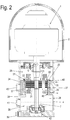
- Fig. 1 shows a separator 1 with a centrifugal drum 2 with a vertical axis of rotation D, which is surrounded by a hood assembly 3, which is supported on a machine frame-like drive housing 4.
- the drive housing 4 can preferably via spring elements, not shown here in sprung execution on a foundation.
- the centrifugal drum 2 is shown here only schematically. It is preferably designed for continuous operation for the continuous clarification and / or separation of a flowable product into one or two liquid phases and possibly a solid phase, in particular in the industrial process.
- her interior is preferably provided with a separation plate stack.
- the Hood assembly 3 is shown only schematically. In particular, it may have a solids catcher and one or more bushings for product feeds and outlets not shown here).
- the preferably single or double conical centrifugal drum 2 is placed on the vertical upper end of a drive spindle 5 here.
- This drive spindle 5 is rotatably mounted with a bearing arrangement, which here has a neck bearing 6 and a foot bearing 7.
- the neck bearing 6 is supported via at least one elastic element radially in a bearing housing 9, which in turn is secured to the drive housing 4.
- the bearing housing 9 to a flange portion 10 which rests on a first - vertically upper - collar 11 on the inner circumference of the drive housing 4 and secured there, here with circumferentially distributed first screws 12.
- the elastic element consists here and preferably and in a simple design of two metallic sleeves 8 ', 8 "', which are connected to each other by means of a ring of elastomeric material 8". The outer ring or the outer sleeve 8 'is machined out here, so that it is accurately guided in the housing.
- the elastic element is fixed here, for example, pressed and thus secured axially and against co-rotation.
- the inner ring or the inner sleeve 8 '" is machined inside, so that the rolling bearing is guided with its outer ring preferably displaceable.
- the neck bearing 6 is preferably formed as a rolling bearing, which rests here on a ring 13, which in turn is placed on the spindle 5 and rests there down on a diameter gradation 14 of the spindle 5. In the elastic element, it is guided vertically displaceable and radially supported.
- the foot bearing 7 is designed as an axial fixed bearing and preferably non-rotatably mounted on the drive spindle 5. It is also articulated on inner ring 18 and outer ring 19, gimbal tiltable but with respect to ring 18 non-rotatably arranged in the drive housing 4 (joint member 15) and / or even formed like a spherical bearing, so that the drive spindle 5 with the drum the precession movements of the centrifugal drum 2 in Operation can follow.
- the rotation of the foot bearing 7 is achieved here by way of example by a pin 42 which is inserted in each case in an opening of the inner ring 18 and the drive housing.
- a rolling bearing is preferably used here, which can absorb the resulting axial forces in a suitable manner.
- Suitable for this example deep groove ball bearings, angular contact ball bearings. If necessary, these bearings can also be arranged in pairs, if required by the male forces.
- the joint bearing described here takes over the gimbal inclination and support.
- the entire unit consisting of spherical plain bearings and roller bearings can be replaced with low forces to be absorbed, in particular axial forces by a self-aligning ball bearing or spherical roller bearings.
- Thetician 7 is here upwards at its inner circumference at a further fürmesserstufung 16 of the drive spindle 5 and downwardly at its outer periphery on a gradation 17 of an outer circumference spherical segment-like inner ring 18, which in turn engages in a correspondingly complementarily shaped outer ring 19 hinged which rests on a gradation 41 of the drive housing 4.
- This arrangement is compact and allows a simple and reliable way to support the weight of the centrifugal drum 2 via the foot bearing on the drive housing. 4
- an electric motor 20 with a rotor 21 and a stator 22 is arranged as a drive device. This is completely between the neck bearing 6 and the demandinglager. 7
- the rotor 21 is arranged and fixed directly on the drive spindle.
- the rotor 21 and the rotatable drive spindle 5 move fixed coupled together, in particular in precession movements of the drive spindle 5 during operation.
- the drive spindle 5 can here at its periphery a suitable contouring - e.g. Stages - for fixing or arranging the rotor 21 have.
- the stator 22 is firmly connected to the drive housing 4. This changes the radial gap width between the stator 22 and the rotor 21 during operation as a result of the movements of the drive spindle 5.
- the drive spindle 5 also carries out its precession movement between the neck bearing 6 and the foot bearing 7 (as a fixed bearing) as a result of the gyro laws, this is limited in this area (stop), so that with the help of a corresponding air gap between the stator 22 and the Motor rotor 21 can be ensured that the rotor 21 and the stator 22 do not touch during operation in spite of radial relative movement.
- Such relative movements may be e.g. imbalances, especially in the range of the resonant frequency of the system during startup of the drum, or for example by movements of the entire machine due to wave influence when used on board ships and possibly have their greatest deflections.
- the bearing formed in the pivot bearing 7 (which essentially takes over the axial support of the centrifugal drum 2) and the elastically supported neck bearing 6 advantageously allows a supercritical operation of the motor rotor 21 with respect to the resonance frequency and the centrifugal drum 2.
- the mass properties of the motor rotor 21 are so small that they do not adversely affect the dynamic behavior of the drive system.
- the separator drum together with the spindle and neck support, approximates a one-shot oscillator excited by the rotating drum and, in particular, by the co-rotating unbalance.
- the elastic neck support significantly reduces its natural frequency compared to nearly rigid constructions.
- the critical speed (or frequency) is that speed at which the forces caused by the rotating drum and co-rotating imbalance cause the machine to resonate. (The excitation frequency (drum speed) is here equal to the natural frequency of the system.) Above this frequency (speed) stabilizes the system, since unbalance and rotor gravity are here on opposite sides of the actual axis of rotation.
- separators are operated at their operating speed well above the critical speed (resonant frequency), so that even a major imbalance without adverse effects of the machine is endured.
- suitable fastening means here one or more (circumferentially distributed) screws 27, is provided.
- stator can be prefabricated in a simple manner as a preassembled unit with the radially outer sleeve body 24 in the drive housing can be attached.
- Fig. 1 and 2 are largely identical and differ essentially only by the axial length of the electric motors 20 and 20 '.
- the axial length of the electric motor 20, 20 ' can vary within a considerable range, which advantageously makes it possible to use identical drive housings 4 for electric motors 20, 20' of different length and power.
- FIG. 1 A comparison of Fig. 1 and 2 makes it clear that with differently long stators 22, the sleeve body 24 used as the interface of the stator 22 to the drive housing 4 still has the same vertical length. Preferably, even an identical sleeve body 24 is used despite a different vertical length.
- the electric motor may be an asynchronous motor or a synchronous motor.
- the drive chamber 28 is designed to be upwardly (except for an annular gap 29 to the drive spindle 5 above the neck bearing 6) and downwardly and laterally largely closed.
- a labyrinth seal or a shaft seal of known design can be used in addition to the annular gap (not shown here).
- stator 22 and the rotor or motor rotor 21 are arranged open in the drive space 28 between the neck bearing 6 and the foot bearing 7.
- the drive spindle 5 is hollow or has an inner centric lubricant line or bore 30 which extends axially from an area below the contemplatlagers 7 through the region of the motor rotor 21 of the electric motor 20 into the region of the neck bearing 6, where the lubricant line 30 preferably via a radial Schmierstoffzu GmbHbohrung 31 opens into the drive chamber 28, in such a way that with the exiting from this bore 31 lubricant lubrication of the neck bearing 6 can take place.
- the lubricant supply bore 31 therefore preferably discharges above the neck bearing 6 into the drive space. Alternatively, it could also open just below the neck bearing 6 in the drive chamber 28, if this ensures sufficient lubrication of the neck bearing 6.
- a lubricant pump (in particular a suction-pipe pump or a centrifugal pump, here realized with a rib arrangement 32 on the inner circumference of the axial lower end of the lubricant bore 31) is integrated in the lower (preferably open) spindle end.
- the fin arrangement together with the dimensioning of the inlet diameter to a particularly precise oil quantity control (setting) and can optionally be adapted to the lubricant or the operating conditions such as the site (ambient temperature) and designed to be interchangeable.
- stator 22 Preferably, outside of the stator 22 one or more in particular vertically extending bores or the like.
- the foot bearing 7 can be located completely below the lubricant level in the lubricant sump 33 or can be arranged completely in the lubricant bath.
- the winding head temperature is usually very high.
- these winding heads are quite far away from the bearings, which is an advantage over the prior art.
- the foot bearing 7 is here in the oil sump, it can also be kept very cool.
- the neck bearing 6 is lubricated with flowing lubricant, it is also better cooled than in an oil mist lubrication, as known in the art.
- the lubricant can flow back through further channels / bores 35 into a region of the drive space 28 lying below the foot bearing 7, to enter the line 30 can.
- a drain plug 39 allows for draining / changing the lubricant.
- the lubricant level is preferably just below the electric motor 20 without having this contact.
- the heat output resulting from the losses of the electric motor can be emitted on the one hand over the surface of the drive housing or a correspondingly designed surface enlargement (for example cooling fins on the outer surface of the drive housing 4 over the entire axial length between the neck bearing and the foot bearing 7 in a correspondingly large configuration).
- a correspondingly designed surface enlargement for example cooling fins on the outer surface of the drive housing 4 over the entire axial length between the neck bearing and the foot bearing 7 in a correspondingly large configuration.
- This cooling medium preferably and particularly advantageously cools both the lubricant and the electric motor (in particular the stator 20).
- Other components such as a coolant pump and possibly a filter to complete the coolant circuit are not shown here, since they are known per se.
- the lubricant flowing through the lubricant passage 34 is cooled.
- the stator 20 is cooled particularly effectively. For clarity's sake Fig. 2 directed.
- the actual electric motor limits here with the sleeve body 24 and the cooling chamber, here the annular chamber 37. But he does not have his own cooling system. This simplifies its installation and also the change, which is also particularly cost-effective by this measure.
- the stator 22 of the electric motor 20 itself can be provided and changed in a particularly simple manner as a prefabricated module. It would also be conceivable to limit the annular chamber with an additional sleeve inside, but this is less preferred.
- the cooling circuit in an area, for example in the region of the chamber, in particular the annular chamber 37, adjacent both to the stator 22 - here the sleeve body 24 - as well as close to the at least one of the holes of the lubricant channel, which the lubricant as a liquid-flowing lubricant Passing the electric motor down into the lubricant sump, a double cooling is achieved in a simple manner.
- one or more seals 40 can advantageously be arranged on the inner circumference of the sleeve body in order to seal the gap between the sleeve body 24 and the collar section 26 (or the cooling chamber).
- the sleeve body 24 thus forms in a structurally particularly simple manner one of the walls of the annular chamber 37.
- Sight glasses 43 in the outer wall allow a visual inspection of the lubrication system, in particular, since one of the sight glasses 43 is vertically at the level of the maximum lubricant level, so that the lubricant level can be monitored, with a second (here upper) sight glass 43 the view in allows the lubricant channel 34 and thus the oil return
Landscapes
- Motor Or Generator Frames (AREA)
- Centrifugal Separators (AREA)
Description
- Die Erfindung betrifft einen Separator mit den Merkmalen des Oberbegriffs des Anspruchs 1.
- Derartige auch für einen industriellen Einsatz geeignete Separatoren, insbesondere auch im kontinuierlichen Betrieb, sind aus dem Stand der Technik an sich bekannt.
- Vielfach erfolgt die Leistungsübertragung vom Elektromotor zum Rotor über einen Antriebsriemen oder durch ein Schraubenradgetriebe.
- Unter den bekannten Systemen gibt es darüber hinaus auch Konstruktionen, bei denen die Trommel, die Antriebsspindel und der elektrische Antriebsmotor starr zu einer baulichen Einheit verbunden sind, welche dann als Ganzes elastisch an einem Maschinengestell abgestützt ist. Beispiele eines derartigen Standes der Technik offenbaren die gattungsgemäße
GB 368 247 FR 1.287.551 DE 1 057 979 und dieDE 43 14 440 C1 . Nachteilig ist, dass derartige Anordnungen relativ groß bauen, insbesondere auch in radialer Richtung (GB 368 247 - Zu nennen ist in diesem Zusammenhang auch die
EP 1 617 952 , welche das konstruktive Grundprinzip derGB 368 247 GB 368 247 - Zum Stand der Technik zu nennen ist schließlich auch noch die
DE 513 192 . Diese Schrift offenbart eine Schleuderspindel, bei welcher der Antriebsmotor zwar in axialer Verlängerung der Drehachse der Schleudertrommel koaxial zu dieser angeordnet ist, bei welcher aber die Antriebsspindel einen Rohrabschnitt durchsetzt, wobei die Antriebsspindel und der Rohrabschnitt bei derDE 513 192 im Bereich eines Fußlagers verbunden sind, wohingegen der Rohrabschnitt und die Antriebsspindel in relativ aufwendiger Bauart getrennte Halslager aufweisen und nur die Antriebsspindel radial elastisch an einem Maschinengestell abgestützt ist. Dieser Art der Konstruktion ist damit sehr aufwendig. Das Antriebsgehäuse selbst ist zweiteilig ausgebildet, wobei ein Oberteil mit einem Flansch auf einem Unterteil aufliegt. Es gibt eine Schmierung mit Öl aber keine Kühlung mit einem Kühlmittel zusätzlich zum Schmiermittel. Der Stator ist direkt am Innenumfang des Antriebsgehäuses befestigt. Insgesamt ist der konstruktive Aufbau der bekannten Konstruktionen relativ aufwendig und nicht flexibel genug an verschiedene Einsatzzwecke anpassbar. Verbesserungswürdig erscheint zudem die Kühlung der bekannten Antriebsvorrichtungen. - Insofern stellen die moderneren Konstruktionen der
DE 10 2006 011 895 ,DE 10 2006 020 467 A1 eine Weiterentwicklung dar. Abweichend von deren Konstruktionsprinzip besteht aber weiter ein Bedarf an kompakten, leicht an verschiedene Einsatzzwecke anpassbaren Separatorantrieben, die über ein ausgereiftes und effizientes Kühlsystem verfügen. - Eine Laborzentrifuge, bei welcher ein Antriebsgehäuse mit einem Schmiermittelsystem geschmiert und einem Kühlmittelsystem gekühlt wird, offenbart die
EP 0 017 344 A1 . Allerdings ist hier der Stator mit dem Rotor als Einheit an der Antriebsspindel gelagert. Zum Stand der Technik der Laborzentrifugen sei ferner dieDE 39 22 639 A1 genannt, bei der unterhalb des Antriebsmotors kein Lager vorgesehen ist. - Die Erfindung hat insofern ausgehend von dem bekannten Stand der Technik die Aufgabe, einen anderen Weg zu gehen und einen Separator zu realisieren, der sich durch eine kompakte Bauart und insbesondere auch durch einen niedrigen Wartungsbedarf, sowie ein effizientes Kühlsystem auszeichnet.
- Die Erfindung löst diese Aufgabe durch den Gegenstand des Anspruchs 1.
- Als besonders vorteilhaft zu erwähnen sind die einfache Montage und Wartung des Separatorantriebs sowie das vorteilhafte Kühlsystem sowohl zur Kühlung des Motors als auch des im Antriebsraum vertikal von oben nach unten zurückfließenden flüssigen Schmiermittels. Ein Erzeugen eines Schmiermittelnebels ist damit nicht erforderlich sondern es kann direkt eine Schmierung der Lager der Antriebsspindel mit fließendem, flüssigem Schmiermittel verwendet werden, so dass kein Schmiermittel in den Elektromotor an sich eintreten kann, was bei der Verwendung eines Ölnebelsystems unvermeidlich wäre. Der Rotor sitzt direkt auf der in diesem Bereich radial beweglichen Antriebsspindel, auf deren Ende die Trommel aufgesetzt ist.
- Dabei ist das Kühlsystem - ein Kühlkreislauf für ein Kühlfluid, insbesondere Wasservorzugsweise und vorteilhaft ganz oder teilweise direkt in das Antriebsgehäuse integriert, wohingegen der Elektromotor - insbesondere der Stator - an sich über keine eigene in ihn eingebaute Flüssigkeitskühlung verfügt. Derart kann der Elektromotor - insbesondere der Stator als vormontierte Baueinheit ohne Flüssigkeitskühlungseinrichtung - besonders kostengünstig ausgelegt werden. Vorzugsweise gibt es zusätzlich zur Kühlung mit dem Kühlmittel eine Schmierung mit einem Schmiermittel. Das Schmiermittel und das Kühlmittel werden vorzugsweise verschiedene Flüssigkeiten benutzt.
- Vorteilhafte Ausgestaltungen sind den Unteransprüchen zu entnehmen.
- Nachfolgend wird die Erfindung anhand von Ausführungsbeispielen unter Bezug auf die Zeichnung näher beschrieben. Es zeigen:
- Fig. 1
- eine Schnittansicht eines schematisiert dargestellten ersten erfindungsgemäßen Separators; und
- Fig. 2
- eine Schnittansicht eines schematisiert dargestellten zweiten erfindungsgemäßen Separators.
-
Fig. 1 zeigt einen Separator 1 mit einer Schleudertrommel 2 mit vertikaler Drehachse D, die von einer Haubenanordnung 3 umgeben ist, die sich auf einem maschinengestellartigen Antriebsgehäuse 4 abstützt. Das Antriebsgehäuse 4 kann über hier nicht dargestellte Fußelemente vorzugsweise in gefederter Ausführung an einem Fundament. - Die Schleudertrommel 2 ist hier nur schematisch dargestellt. Sie ist vorzugsweise für einen kontinuierlichen Betrieb zum kontinuierlichen Klären und/oder Trennen eines fließfähigen Produktes in eine oder zwei Flüssigkeitsphasen und ggf. eine Feststoffphase - insbesondere im industriellen Prozess - ausgelegt. Hierzu ist ihr Innenraum vorzugsweise mit einem Trenntellerstapel versehen. Auch die Haubenanordnung 3 ist lediglich schematisch dargestellt. Sie kann insbesondere einen Feststofffänger aufweisen sowie eine oder mehrere Durchführungen für hier nicht dargestellte Produktzuleitungen und -ableitungen). Diese Merkmale sind dem Fachmann seit langem bekannt und bedürfen hier keiner näheren Darstellung.
- Die vorzugsweise einfach oder doppelt konische Schleudertrommel 2 ist auf das hier vertikale obere Ende einer Antriebsspindel 5 aufgesetzt. Diese Antriebsspindel 5 ist mit einer Lageranordnung, die hier ein Halslager 6 und ein Fußlager 7 aufweist, drehbar gelagert.
- Das Halslager 6 ist dabei über wenigstens ein elastisches Element radial in einem Lagergehäuse 9 abgestützt, welches wiederum am Antriebsgehäuse 4 befestigt ist. Hier weist das Lagergehäuse 9 dazu einen Flanschabschnitt 10 auf, der auf einem ersten - vertikal oberen - Bund 11 am Innenumfang des Antriebsgehäuse 4 aufliegt und dort befestigt ist, hier mit umfangsverteilten ersten Schrauben 12. Vorzugsweise und vorteilhaft bilden das Lagergehäuse 9 und das Halslager eine vormontierte und austauschbare Baueinheit aus. Das elastische Element besteht hier sowie vorzugsweise und in einfacher Bauart aus zwei metallischen Hülsen 8', 8"', die mittels einem Ring aus Elastomermaterial 8" miteinander verbunden sind. Der äußere Ring bzw. die äußere Hülse 8' ist hier außen bearbeitet, so dass er passgenau im Gehäuse geführt wird. Vorzugsweise ist das elastische Element hier fixiert, beispielsweise eingepresst und somit axial und gegen Mitdrehen gesichert. Der innere Ring bzw. die innere Hülse 8'" ist innen bearbeitet, so dass das Wälzlager mit seinem Außenring vorzugsweise verschieblich geführt wird.
- Weitere bekannte alternative Bauformen für diese elastische Halslagerabstützung sind möglich, zum Beispiel: Federkolben mit Schraubenfedern, Blattfedern, Luftfedern usw..
- Das Halslager 6 ist vorzugsweise als Wälzlager ausgebildet, welches hier auf einem Ring 13 aufliegt, der wiederum auf die Spindel 5 aufgesetzt ist und dort nach unten hin auf einer Durchmesserstufung 14 der Spindel 5 aufliegt. Im elastischen Element ist es vertikal verschieblich geführt und radial abgestützt.
- Das Fußlager 7 ist als axiales Festlager ausgebildet und vorzugsweise verdrehgesichert auf der Antriebsspindel 5 angeordnet. Es ist ferner über Innenring 18 und Außenring 19 gelenkig, kardanisch neigbar aber in Bezug auf Ring 18 nicht drehbar im Antriebsgehäuse 4 angeordnet (Gelenkelement 15) und/oder selbst gelenklagerartig ausgebildet, so dass die Antriebsspindel 5 mit der Trommel den Präzessionsbewegungen der Schleudertrommel 2 im Betrieb folgen kann.
- Die Verdrehsicherung des Fußlagers 7 wird hier beispielhaft durch einen Stift 42 erreicht, der jeweils in eine Öffnung des Innenringes 18 und des Antriebsgehäuses eingesetzt ist.
- Dabei wird das Gewicht der Schleudertrommel mit allen Antriebsteilen, die mit der Spindel verbunden sind, im Wesentlichen über das untere Fußlager 7 im Antriebsgehäuse 4 abgestützt. Entsprechend wird hier vorzugsweise ein Wälzlager eingesetzt, das in geeigneter Weise die entstehenden Axialkräfte aufnehmen kann. Geeignet sind dazu beispielsweise Rillenkugellager, Schrägkugellager. Bei Bedarf können diese Lager auch paarweise angeordnet werden, wenn die aufzunehmenden Kräfte dieses erfordern.
- Das beschriebene Gelenklager übernimmt hierbei die kardanische Neigbarkeit und Abstützung.
- Die gesamte Einheit bestehend aus Gelenklager und Wälzlager kann bei geringen aufzunehmenden Kräften, insbesondere Axialkräften durch ein Pendelkugellager oder Pendelrollenlager ersetzt werden.
- Das Fußlager 7 liegt hier nach oben hin an seinem Innenumfang an einer weiteren Durchmesserstufung 16 der Antriebsspindel 5 an und nach unten hin an seinem Außenumfang an einer Stufung 17 eines am Außenumfang kugelsegmentartigen Innenringes 18, der wiederum in einen entsprechend komplementär geformten Außenring 19 gelenkig eingreift, der auf einer Stufung 41 des Antriebsgehäuses 4 aufliegt.
- Diese Anordnung baut kompakt und ermöglicht auf einfache und zuverlässige Weise die Abstützung des Gewichtes der Schleudertrommel 2 über das Fußlager am Antriebsgehäuse 4.
- In dem axialen Bereich zwischen den Lagern ist als Antriebseinrichtung ein Elektromotor 20 mit einem Rotor 21 und einem Stator 22 angeordnet. Dieser liegt vollständig zwischen dem Halslager 6 und dem Fußlager 7.
- Dabei ist der Rotor 21 direkt auf der Antriebsspindel angeordnet und befestigt. Dadurch bewegen sich der Rotor 21 und die drehbare Antriebsspindel 5 fest gekoppelt gemeinsam, insbesondere auch bei Präzessionsbewegungen der Antriebsspindel 5 im Betrieb. Die Antriebsspindel 5 kann hier an ihrem Umfang eine geeignete Konturgebung - z.B. Stufungen - zum Festlegen bzw. Anordnen des Rotors 21 aufweisen.
- Der Stator 22 ist dabei fest mit dem Antriebsgehäuse 4 verbunden. Damit verändert sich der radiale Spaltweite zwischen dem Stator 22 und dem Rotor 21 im Betrieb infolge der Bewegungen der Antriebsspindel 5.
- Zwar führt die Antriebsspindel 5 auch zwischen dem Halslager 6 und dem Fußlager 7 (als Festlager) ihre Präzessionsbewegung infolge der Kreiselgesetze aus, diese ist jedoch in diesem Bereich definiert begrenzbar (Anschlag), so das mit Hilfe eines entsprechenden Luftspaltes zwischen dem Stator 22 und dem Motorläufer 21 sichergestellt werden kann, dass sich der Rotor 21 und der Stator 22 im Betrieb trotz radialer Relativbewegung nicht berühren. Solche Relativbewegungen können z.B. durch Unwuchten, insbesondere im Bereich der Resonanzfrequenz des Systems beim Hochlauf der Trommel, oder beispielsweise durch Bewegungen der kompletten Maschine infolge Welleneinfluss bei Einsatz an Bord von Schiffen auftreten und ggf. ihren größten Auslenkungen haben.
- Die in dem als Gelenklager ausgebildeten Fußlager 7 (das im Wesentlichen die axiale Abstützung der Schleudertrommel 2 übernimmt) und dem elastisch abgestützten Halslager 6 gebildete Lagerung ermöglicht in vorteilhafter Weise in Hinsicht auf die Resonanzfrequenz einen überkritischen Betrieb des Motorläufers 21 und der Schleudertrommel 2. Die Masseneigenschaften des Motorläufers 21 sind dabei so klein, dass sie sich nicht negativ auf das dynamische Verhalten des Antriebsystems auswirken.
- Die Separatorentrommel bildet zusammen mit der Spindel und der Halslagerabstützung in erster Annäherung einen Ein-Massen-Schwinger, der durch die rotierende Trommel und insbesondere durch die mitrotierende Unwucht angeregt wird. Die elastische Halslagerabstützung senkt dessen Eigenfrequenz gegenüber annähernd starren Konstruktionen deutlich ab. Als kritische Drehzahl (bzw. Frequenz) wird diejenige Drehzahl bezeichnet, bei der die Kräfte verursacht durch die rotierende Trommel und mitrotierende Unwucht die Maschine in Resonanzschwingungen versetzen. (Die Erregerfrequenz (Trommeldrehzahl) ist hier gleich der Eigenfrequenz des Systems.) Oberhalb dieser Frequenz (Drehzahl) stabilisiert sich das System, da Unwucht und Rotorschwerpunkt hier auf gegenüberliegenden Seiten der tatsächlichen Drehachse liegen.
- Üblicherweise werden Separatoren mit ihrer Betriebsdrehzahl deutlich oberhalb der kritischen Drehzahl (Resonanzfrequenz) betrieben, so dass auch eine größere Unwucht ohne schädliche Auswirkungen von der Maschine ertragen wird.
- Vorzugsweise und kompakt sind anders als im Stand der Technik der gesamte Stator 22 mit dem Wicklungsbereich 23 mit den Wickelköpfen und den Statorblechpaketen 23' und Hülsenkörper 24 und auch der gesamte Rotor 21 axial zwischen dem Halslager 6 und dem Fußlager 7 angeordnet.
- Zur Befestigung des Stators 22 an dem Maschinengehäuse 4 ist hier in vorteilhafter Weise vorgesehen, den Wicklungsbereich 23 mitsamt dem oder den Statorblechpaketen 23' des Stators 22 miteinem Hülsenkörper 24 zu umgeben, der - vorzugsweise an seinem vertikal oberen Ende - einen Flanschabschnitt 25 aufweist, welcher auf einem korrespondierenden Bundabschnitt 26 am Innenumfang des Antriebsgehäuses 4 anliegt bzw. hier aufliegt. Zur Befestigung des Flanschabschnittes 25 und dem Bundabschnitt 26 sind geeignete Befestigungsmittel, hier eine oder mehrere (umfangsverteilte) Schrauben 27, vorgesehen.
- An der Auslegung des Stators ist zunächst besonders vorteilhaft, dass der Stator in einfacher Weise vorgefertigt als vormontierte Einheit mit dem radial außen liegenden Hülsenkörper 24 in dem Antriebsgehäuse befestigt werden kann.
- Zudem können aufgrund der gewählten Konstruktionsart Motoren (Statoren 22 und Rotoren 21) verschiedener Länge und damit verschiedener Motorleistungen in einfacher Weise an dem Flanschabschnitt 25 festgelegt werden, was insbesondere auch ein Vergleich der
Figuren 1 und2 veranschaulicht. - Die Konstruktionen der
Fig. 1 und2 sind weitgehend baugleich und unterscheiden sich im Wesentlichen nur durch die axiale Baulänge der Elektromotoren 20 und 20'. Wie ersichtlich, kann die axiale Baulänge des Elektromotors 20, 20' innerhalb eines beachtlichen Bereiches variieren, was es in vorteilhafter Weise ermöglicht, gleiche Antriebsgehäuse 4 für Elektromoren 20, 20' unterschiedlicher Länge und Leistung einzusetzen. - Ein Vergleich der
Fig. 1 und2 macht deutlich, dass bei unterschiedlich langen Statoren 22 der verwendete Hülsenkörper 24 als die Schnittstelle des Stators 22 zum Antriebsgehäuse 4 dennoch die gleiche vertikale Baulänge aufweist. Vorzugsweise wird sogar ein baugleicher Hülsenkörper 24 trotz einer unterschiedlichen vertikalen Länge verwendet. - Der Elektromotor kann ein Asynchronmotor oder ein Synchronmotor sein.
- Vorzugsweise und vorteilhaft ist der Antriebsraum 28 nach oben hin (bis auf einen Ringspalt 29 zur Antriebsspindel 5 oberhalb des Halslagers 6) und nach unten hin sowie seitlich weitestgehend geschlossen ausgelegt.
- Bei Bedarf nach einer höherwertigen Abdichtung zwischen Antriebsraum und Trommelraum kann zusätzlich zum Ringspalt eine Labyrinthdichtung oder eine Wellenringdichtung bekannter Bauart eingesetzt werden (hier nicht dargestellt).
- Der Stator 22 und der Rotor bzw. Motorläufer 21 sind offen im Antriebsraum 28 zwischen dem Halslager 6 und dem Fußlager 7 angeordnet.
- Besondere Vorteile bieten bei den Konstruktionen der
Fig. 1 und2 auch die Ausgestaltung der Funktionsbereiche "Schmierung" und "Kühlung der Komponenten des Antriebsbereiches und des Schmiermittels". - Zunächst sei die Schmierung näher betrachtet.
- Die Antriebsspindel 5 ist hohl ausgebildet bzw. weist eine innere zentrische Schmiermittelleitung oder -bohrung 30 auf, welche sich axial von einem Bereich unterhalb des Fußlagers 7 durch den Bereich des Motorläufers 21 des Elektromotors 20 bis in den Bereich des Halslagers 6 erstreckt, wo die Schmiermittelleitung 30 vorzugsweise über eine radiale Schmiermittelzuführbohrung 31 in den Antriebsraum 28 mündet, und zwar derart, dass mit dem aus dieser Bohrung 31 austretendem Schmiermittel eine Schmierung des Halslagers 6 erfolgen kann.
- Vorzugsweise mündet die Schmiermittelzuführbohrung 31 daher oberhalb des Halslagers 6 in den Antriebsraum. Alternativ könnte sie auch kurz unterhalb des Halslagers 6 in den Antriebsraum 28 münden, wenn hierdurch eine genügende Schmierung des Halslagers 6 sichergestellt ist.
- In das untere (vorzugsweise offene) Spindelende ist hier eine Schmiermittelpumpe (insbesondere eine Saugrohrpumpe oder eine Zentrifugalpumpe; hier mit einer Rippenanordnung 32 am Innenumfang des axialen unteren Ende der Schmiermittelbohrung 31 realisiert) integriert. Die Rippenanordnung lässt zusammen mit der Dimensionierung des Eintrittsdurchmessers eine besonders präzise Ölmengensteuerung (-einstellung) zu und kann ggf. auf das Schmiermittel bzw. die Betriebsverhältnisse wie den Aufstellungsort (Umgebungstemperatur) abgestimmt werden und austauschbar gestaltet sein.
- Da das untere Spindelende der Antriebsspindel 5 mit der Schmiermittelpumpe in einen Schmiermittelsumpf 33 eintaucht, erfolgt durch die Antriebsspindel 5 und deren Leitung 30 und die Schmiermittelzuführbohrung 31 in einfacher und zuverlässiger Weise eine Schmierung des Halslagers 6.
- Durch das Halslager 6 tretendes und dieses schmierende Schmiermittel (insbesondere Öl) läuft oder tropft im Antriebsraum 28 nach unten.
- Es ist daher vorteilhaft, dass unterhalb des Halslagers 6 zwischen diesem und dem Elektromotor 20 auf der Antriebsspindel 5 der Ring 13 angeordnet ist, welcher einen Radialbund 38 aufweist, so dass er im Betrieb einen Schleuderring bildet, welcher das Schmiermittel im Antriebsraum 28 bei Drehungen der Antriebsspindel 5 radial nach außen schleudert, was verhindert, dass das Schmiermittel direkt in den Elektromotor 20 tropfen kann. Hierdurch wird verhindert, dass Öl durch den Spalt zwischen dem Stator 22 und dem Rotor 21 den Weg zurück in den Ölsumpf nimmt. Das Öl läuft an der Innenwand des Antriebsgehäuses 4 nach unten und durch die Bohrungen zurück in den Öl- bzw. Schmiermittelsumpf 33. Der Motor ist hier schematisiert unterschiedlich links und rechts der Drehachse dargestellt, um das Verständnis zu erleichtern.
- Vorzugsweise sind außerhalb des Stators 22 einer oder mehrere insbesondere vertikal verlaufende Bohrungen oder dgl. als Schmiermittelkanal 34 im radial nach innen kragenden Bundabschnitt 26 des Maschinengehäuses 4 ausgebildet, durch welche das Schmiermittel im Wesentlichen radial außen auf seinem Weg nach unten in den Schmiermittelsumpf 33 an dem Stator 22 und dem Motorläufer 11 vorbeigeleitet wird.
- Das Fußlager 7 kann sich vollständig unterhalb des Schmiermittelspiegels im Schmiermittelsumpf 33 befinden bzw. vollständig im Schmiermittelbad angeordnet sein.
- Die Wickelkopftemperatur liegt in der Regel sehr hoch. Hier sind diese Wickelköpfe von den Lagern recht weit entfernt, was gegenüber dem Stand der Technik ein Vorteil ist. Da das Fußlager 7 hier im Ölsumpf liegt, kann es zudem besonders gut kühl gehalten werden. Da das Halslager 6 mit fließendem Schmierstoff geschmiert wird, wird es zudem ebenfalls besser gekühlt als bei einer Ölnebelschmierung, wie sie aus dem Stand der Technik bekannt ist.
- Dabei kann das Schmiermittel durch weitere Kanäle/Bohrungen 35 wieder in einen unterhalb des Fußlagers 7 liegenden Bereich des Antriebsraums 28 zurückfließen, um in die Leitung 30 eintreten zu können. Optional ermöglicht eine Ablassschraube 39 ein Ablassen/Wechseln des Schmiermittels.
- Der Schmiermittelspiegel liegt vorzugsweise kurz unterhalb des Elektromotors 20 ohne mit diesem Kontakt zu haben.
- Die aus den Verlusten des Elektromotors resultierende Wärmeleistung kann einerseits über die Oberfläche des Antriebsgehäuses oder eine entsprechend gestaltete Oberflächenvergrößerung (z.B. Kühlrippen an der Außenfläche des Antriebsgehäuses 4 über die gesamte axiale Länge zwischen dem Halslager und dem Fußlager 7 in entsprechend großer Ausgestaltung) abgestrahlt werden. Alternativ oder ergänzend ist es denkbar, durch Kanäle und ggf. Kammern im Antriebsgehäuse ein Kühlmedium zu leiten, um das Schmiermittel zu kühlen.
- Vorzugsweise und besonders vorteilhaft kühlt dieses Kühlmedium dabei sowohl das Schmiermittel als auch den Elektromotor (insbesondere den Stator 20).
- Dies wird hier auf einfache Weise wie folgt realisiert.
- Bei dem Antriebsgehäuse der
Fig. 1 und2 sind eine Kühlmittelzuleitung und eine Kühlmittelableitung - 35, 36 - für eine Kühlflüssigkeit oder ein kühlendes Gas vorgesehen, welche in wenigstens eine Kammer, vorzugsweise eine Ringkammer 37 münden, welche im Antriebsgehäuse 4 oder in baulich besonders einfacher und praktischer Weise zwischen dem Antriebsgehäuse 4 und Abschnitten des Hülsenkörpers 24 ausgebildet ist. Weitere Komponenten wie eine Kühlmittelpumpe und ggf. ein Filter zur Vervollständigung des Kühlmittelkreislaufs sind hier nicht dargestellt, da sie an sich bekannt sind. - Derart wird das durch den Schmiermittelkanal 34 strömende Schmiermittel gekühlt. Darüber hinaus wird aber auch der Stator 20 besonders effektiv gekühlt. Hierzu sei der Übersichtlichkeit halber auf
Fig. 2 verwiesen. - In
Fig.2 ist ersichtlich, dass die Kühlung des Elektromotors 20 im Wesentlichen durch die Kammer, insbesondere die Ringkammer des in das Antriebsgehäuse 4 integrierten Kühlkreislaufes erfolgt. - Der eigentliche Elektromotor begrenzt zwar hier mit dem Hülsenkörper 24 auch die Kühlkammer, hier die Ringkammer 37. Er muss aber selbst kein eigenes Kühlsystem aufweisen. Dies vereinfacht seinen Einbau und auch den Wechsel, der zudem durch diese Maßnahme besonders kostengünstig wird. Der Stator 22 des Elektromotors 20 selbst kann in besonders einfacher Weise als vorgefertigtes Modul bereitgestellt und gewechselt werden. Es wäre auch denkbar, die Ringkammer mit einer zusätzlichen Hülse innen zu begrenzen, was aber weniger bevorzugt wird.
- Da der Kühlkreislauf in einem Bereich, beispielsweise im Bereich der Kammer, insbesondere der Ringkammer 37, sowohl an den Stator 22 - hier den Hülsenkörper 24 - als auch nahe an die mindestens eine der Bohrungen des Schmiermittelkanals angrenzt, welche das Schmiermittel als flüssig fließender Schmierstoff an dem Elektromotor vorbei nach unten in den Schmiermittelsumpf zurückleiten, wird in einfacher Weise eine Doppelkühlung erreicht. Dabei können vorteilhaft am Innenumfang des Hülsenkörpers eine oder mehrere Dichtungen 40 angeordnet sein, um den Spalt zwischen dem Hülsenkörper 24 und dem Bundabschnitt 26 (bzw. die Kühlkammer) abzudichten. Der Hülsenkörper 24 bildet damit in konstruktiv besonders einfacher Weise eine der Wandungen der Ringkammer 37 aus.
- Schaugläser 43 in der Außenwandung erlauben eine visuelle Kontrolle insbesondere des Schmiersystems, insbesondere, da hier eines des Schaugläser 43 vertikal auf der Höhe des maximalen Schmiermittelpegels liegt, so dass der Schmiermittelpegel überwacht werden kann, wobei ein zweites (hier oberes) Schauglas 43 den Blick in den Schmiermittel-Kanal 34 und damit den Ölrückfluss ermöglicht
- Da der Antrieb bis auf das Hals- und das Fußlager 6, 7 verschleißarm läuft, entfällt ein Großteil des üblichen Wartungsaufwandes, was die Betriebskosten senkt.
Bezugszeichen Separator 1 Schleudertrommel 2 Haubenanordnung 3 Antriebsgehäuse 4 Antriebsspindel 5 Halslager 6 Fußlager 7 Hülsen 8', 8'" Elastomer 8" Lagergehäuse 9 Flanschabschnitt 10 Bund 11 Schrauben 12 Ring 13 Durchmesserstufung 14 Gelenkelement 15 Durchmesserstufung 16 Stufung 17 Innenring 18 Außenring 19 Elektromotor 20 Rotor 21 Stator 22 Wicklungsbereich 23 Statorblechpaket 23' Hülsenkörper 24 Flanschabschnitt 25 Bundabschnitt 26 Schrauben 27 Antriebsraum 28 Ringspalt 29 Schmiermittelleitung 30 Schmiermittelzuführbohrung 31 Rippen 32 Schmiermittelsumpf 33 Schmiermittelkanal 34 Kanäle 35, 36 Ringkammer 37 Radialbund 38 Ablassschraube 39 Dichtungen 40 Stufung 41 Stift 42 Schaugläser 43 Drehachse D
Claims (22)
- Separator (1), der folgendes aufweist:a. eine Schleudertrommel (2) mit vertikaler Drehachse (D),b. eine Antriebsspindel (5) für die Schleudertrommel (2), die mit einem Halslager (6) und einem Fußlager (7) drehbar in einem Antriebsgehäuse (4) gelagert ist, das einen Antriebsraum (28) umgibt bzw. ausbildet,c. einen elektrischen Antriebsmotor (20), der einen Stator (22) und einen Motorläufer (21) aufweist,d. wobei der Motorläufer (21) direkt auf der Antriebsspindel (5) im axialen Bereich zwischen dem Fußlager (7) und dem Halslager (6) in dem Antriebsraum (28) des Antriebsgehäuses (4) angeordnet ist,e. wobei der Stator (22) ferner direkt im Antriebsgehäuse (4) abgestützt ist und wobei zwischen dem Stator (22) und dem Motorläufer (21) ein Luftspalt besteht,f. wobei der Stator (22) und der Motorläufer (21) offen im ansonsten nach außen ganz oder im Wesentlichen geschlossenen Antriebsraum (28) zwischen dem Halslager (6) und dem Fußlager (7) angeordnet sind.g. wobei ein Schmiersystem zur Schmierung insbesondere des Halslagers (6) und des Fußlagers (7) mit einem Schmiermittel vorgesehen ist, welches ganz oder teilweise direkt in den Antriebsraum (28) integriert ist,dadurch gekennzeichnet, dass ferner wenigstens folgende Merkmale realisiert sind:h. es ist ferner ein Kühlmittelkreislauf für ein fließfähiges Kühlmittel vorgesehen, welcher ganz oder teilweise direkt in das Antriebsgehäuse (4) integriert ist,i. wobei das Kühlmittelsystem abschnittsweise an einen Schmiermittelkanal (34) zur Durchleitung von flüssigem und im Antriebsraum fließenden Schmiermittel angrenzt und dass es ferner abschnittsweise an den Stator (22) angrenzt,j. der Stator (22) weist einen Flanschhabschnitt (25) zur Anlage, insbesondere Auflage, an einem korrespondierenden Bundabschnitt (26) des Antriebsgehäuses auf.
- Separator nach Anspruch 1, dadurch gekennzeichnet, dass das Kühlmittelsystem eine Kammer, insbesondere eine Ringkammer (37) aufweist.
- Separator nach Anspruch 2, dadurch gekennzeichnet, dass Kühlmittelkanäle (35, 36) in wenigstens einer Wandung des Antriebsgehäuses (4) ausgebildet sind, welche in die Kammer münden.
- Separator nach Anspruch 3, dadurch gekennzeichnet, dass die Kammer, insbesondere die Ringkammer direkt an den Schmiermittelkanal (34) und direkt an den Stator (22) angrenzt.
- Separator nach einem der vorstehenden Ansprüche, dadurch gekennzeichnet, dass der Stator (22) an seinem Außenumfang einen Hülsenkörper (24) aufweist.
- Separator nach Anspruch 5, dadurch gekennzeichnet, dass der Stator (22) mit dem Hülsenkörper (24) eine vormontierte, wechselbare Baueinheit bildet.
- Separator nach einem der vorstehenden Ansprüche 5 oder 6, dadurch gekennzeichnet, dass der Hülsenkörper (24) im montierten Zustand im Antriebsgehäuse (4) eine Begrenzungswand der Kammer, insbesondere der Ringkammer (27) des Kühlmittelkreislaufes ausbildet.
- Separator nach einem der vorstehenden Ansprüche 5 bis 7, dadurch gekennzeichnet, dass der Hülsenkörper (24) den Flanschabschnitt (25) aufweist, welcher auf dem korrespondierenden Bundabschnitt (26) am Innenumfang des Antriebsgehäuses (4) aufliegt.
- Separator nach einem der vorstehenden Ansprüche, dadurch gekennzeichnet, dass das Halslager (6) in einem Lagergehäuse (9) angeordnet ist, das einen Flanschabschnitt (10) aufweist, wobei das Lagergehäuse (9) und das Halslager eine vormontierte und austauschbare Baueinheit bilden.
- Separator nach einem der vorstehenden Ansprüche, dadurch gekennzeichnet, dass das Halslager (6) über wenigstens ein elastisches Element im Antriebsgehäuse (4) abgestützt ist und dass das Fußlager (7) gelenklagerartig ausgebildet oder im Antriebsgehäuse (4) gelenkig angeordnet ist, so dass die Antriebsspindel (5) Präzessionsbewegungen der Schleudertrommel (2) im Betrieb folgen kann.
- Separator nach einem der vorstehenden Ansprüche, dadurch gekennzeichnet, dass das rotierende System mit der Schleudertrommel und der Antriebsspindel (5) im Wesentlichen axial über das Fußlager (7) im Antriebsgehäuse (4)abgestützt ist.
- Separator nach einem der vorstehenden Ansprüche, dadurch gekennzeichnet, dass die Antriebsspindel (5) hohl ausgebildet ist und eine axiale innere Schmiermittelleitung (30) aufweist, welche sich von einem Bereich unterhalb des Fußlagers (7) axial durch den Bereich des Motorläufers/Rotors (21) bis in den Bereich des Halslagers (6) erstreckt, wo die Schmiermittelleitung (30) in den Antriebsraum (28) mündet.
- Separator nach einem der vorstehenden Ansprüche, dadurch gekennzeichnet, dass eine Schmiermittelzuführbohrung (31) oberhalb oder unterhalb des Halslagers (6) in den Antriebsraum mündet.
- Separator nach einem der vorstehenden Ansprüche, dadurch gekennzeichnet, dass am unteren Spindelende der Antriebsspindel (5) eine Schmiermittelpumpe angeordnet oder ausgebildet ist.
- Separator nach dem vorstehendem Anspruch, dadurch gekennzeichnet, dass die Schmiermittelpumpe als Zentrifugalpumpe oder dass die Schmiermittelpumpe als Saugrohrpumpe ausgebildet ist.
- Separator nach einem der vorstehenden Ansprüche, dadurch gekennzeichnet, dass in dem axialen Bereich zwischen dem Halslager (6) und dem Elektromotor (20) auf der Antriebsspindel (5) ein Schleuderring (13) angeordnet oder ausgebildet ist.
- Separator nach einem der vorstehenden Ansprüche, dadurch gekennzeichnet, dass ein Schmiermittelsumpf (33) im unteren Bereich des Antriebsraums (28) ausgebildet ist, in welchen das aus dem Schmiermittelkanal (34) zurückfließende Schmiermittel zurückfließt.
- Separator nach einem der vorstehenden Ansprüche, dadurch gekennzeichnet, dass das Schmiersystem insgesamt als Kreislaufsystem in den Antriebsraum (28) integriert ist.
- Separator nach einem der vorstehenden Ansprüche, dadurch gekennzeichnet, dass außerhalb des Stators (22) eine oder mehrere insbesondere vertikal verlaufende Bohrungen als der Schmiermittelkanal (34) im Antriebsgehäuse (4) ausgebildet sind, durch welche Schmiermittel im Wesentlichen radial außen an dem Stator (22) und dem Motorläufer (21) vorbeigeleitet wird.
- Separator nach einem der vorstehenden Ansprüche, dadurch gekennzeichnet, dass sich das Fußlager (7) im Betrieb vollständig unterhalb des Schmiermittelspiegels befindet bzw. vollständig im Schmiermittelsumpf angeordnet ist.
- Separator nach einem der vorstehenden Ansprüche, dadurch gekennzeichnet, dass der Schmiermittelspiegel im Betrieb unterhalb des Elektromotors (20) liegt.
- Separator nach einem der vorstehenden Ansprüche, dadurch gekennzeichnet, dass eines oder mehrere Schaugläser (43) zur visuellen Kontrolle insbesondere des Schmiersystems, insbesondere von einem oder beiden Parameter(n) "Schmiermittelpegel" und "Schmiermittel im Schmiermittelkanal" vorgesehen ist/sind.
Applications Claiming Priority (2)
| Application Number | Priority Date | Filing Date | Title |
|---|---|---|---|
| DE102012110846.3A DE102012110846A1 (de) | 2012-11-12 | 2012-11-12 | Separator mit Direktantrieb |
| PCT/EP2013/073117 WO2014072318A2 (de) | 2012-11-12 | 2013-11-06 | Separator mit direktantrieb |
Publications (2)
| Publication Number | Publication Date |
|---|---|
| EP2916961A2 EP2916961A2 (de) | 2015-09-16 |
| EP2916961B1 true EP2916961B1 (de) | 2019-10-09 |
Family
ID=49582728
Family Applications (1)
| Application Number | Title | Priority Date | Filing Date |
|---|---|---|---|
| EP13789760.9A Active EP2916961B1 (de) | 2012-11-12 | 2013-11-06 | Separator mit direktantrieb |
Country Status (12)
| Country | Link |
|---|---|
| US (1) | US9981275B2 (de) |
| EP (1) | EP2916961B1 (de) |
| JP (1) | JP2016505352A (de) |
| KR (1) | KR20150084034A (de) |
| CN (1) | CN104797343A (de) |
| AU (1) | AU2013343679B2 (de) |
| BR (1) | BR112015010479B1 (de) |
| CA (1) | CA2889766C (de) |
| DE (1) | DE102012110846A1 (de) |
| RU (1) | RU2015121635A (de) |
| SG (1) | SG11201503572QA (de) |
| WO (1) | WO2014072318A2 (de) |
Families Citing this family (11)
| Publication number | Priority date | Publication date | Assignee | Title |
|---|---|---|---|---|
| SE533089C2 (sv) * | 2008-05-13 | 2010-06-22 | Alfa Laval Corp Ab | Centrifugalseparator |
| SE532905C2 (sv) * | 2008-09-22 | 2010-05-04 | Alfa Laval Corp Ab | Centrifugalseparator |
| DE102013100180A1 (de) * | 2012-03-26 | 2013-09-26 | Gea Mechanical Equipment Gmbh | Separatoranordnung |
| DE102012110846A1 (de) * | 2012-11-12 | 2014-05-15 | Gea Mechanical Equipment Gmbh | Separator mit Direktantrieb |
| EP3075455B1 (de) * | 2015-03-31 | 2017-12-06 | Alfa Laval Corporate AB | Kühlung oder heizung von lagern in einem zentrifugalabscheider |
| DE102015108741A1 (de) * | 2015-06-02 | 2016-12-08 | Gea Mechanical Equipment Gmbh | Separator |
| CN105057120A (zh) * | 2015-09-11 | 2015-11-18 | 戴杰 | 一种转鼓下支承装置 |
| DE102017114649A1 (de) | 2017-06-30 | 2019-01-03 | Gea Mechanical Equipment Gmbh | Separator mit Direktantrieb |
| DE102017215784A1 (de) * | 2017-09-07 | 2019-03-07 | Zf Friedrichshafen Ag | Getriebe für ein Kraftfahrzeug |
| EP3878559A1 (de) | 2020-03-12 | 2021-09-15 | Alfa Laval Corporate AB | Zentrifugalabscheider |
| DE102022117310A1 (de) | 2022-07-12 | 2024-01-18 | Gea Westfalia Separator Group Gmbh | Verfahren zur Überwachung und Regelung der Kühlmitteltemperatur einer Antriebvorrichtung eines Separators |
Citations (7)
| Publication number | Priority date | Publication date | Assignee | Title |
|---|---|---|---|---|
| US4322030A (en) | 1979-03-14 | 1982-03-30 | Beckman Instruments, Inc. | Lubrication and cooling system for a high speed ultracentrifuge drive assembly |
| US4946433A (en) | 1988-07-18 | 1990-08-07 | Gorodissky Boris P | Centrifuge drive |
| US5848959A (en) | 1994-03-11 | 1998-12-15 | Westfalia Separator Aktiengesellschaft | Lubicated vertical transmission shaft for driving a centrifugal drum |
| US6527085B1 (en) | 2000-11-14 | 2003-03-04 | Tecumseh Products Company | Lubricating system for compressor |
| WO2004089550A1 (en) | 2003-04-08 | 2004-10-21 | Alfa Laval Corporate Ab | A driving device for a centrifugal separator |
| US20050065010A1 (en) | 2002-03-22 | 2005-03-24 | Reinhard Moss | Separator |
| WO2011101222A1 (de) | 2010-02-19 | 2011-08-25 | Magna Powertrain Ag & Co Kg | Elektrische antriebseinheit |
Family Cites Families (44)
| Publication number | Priority date | Publication date | Assignee | Title |
|---|---|---|---|---|
| DE513192C (de) | 1930-11-24 | Ramesohl & Schmidt Akt Ges | Unterteilte Schleuderspindel | |
| DE570729C (de) * | 1929-06-07 | 1933-02-20 | Siemens Schuckertwerke Akt Ges | Durch Elektromotor angetriebene Schleudermaschine |
| GB368247A (en) | 1929-08-31 | 1932-03-03 | Gen Electric | Improvements in and relating to methods of mounting high speed shafts |
| US2597405A (en) * | 1946-09-28 | 1952-05-20 | American Tool & Machine Co | Combined bearing and stabilizing mechanism for centrifugal separators |
| BE554838A (de) | 1956-02-26 | |||
| FR1287551A (fr) | 1961-02-02 | 1962-03-16 | Garin Ets | Appareil tel qu'écrémeuse |
| US3257235A (en) * | 1961-10-09 | 1966-06-21 | American Factors Ass Ltd | Shaft lubrication system for continuous centrifugal |
| US3318644A (en) * | 1965-02-24 | 1967-05-09 | Gen Motors Corp | Centrifugal bearing lubrication system |
| US3604769A (en) * | 1968-09-23 | 1971-09-14 | Cryogenic Technology Inc | Temperature-controlled spindle for centrifuges and similar apparatus |
| JPS50144367U (de) * | 1974-05-16 | 1975-11-28 | ||
| US4226359A (en) * | 1979-03-14 | 1980-10-07 | Beckman Instruments, Inc. | Direct drive high speed ultracentrifuge |
| US4541736A (en) * | 1984-04-30 | 1985-09-17 | Beckman Instruments, Inc. | Centrifugal oil pump flow proportioning and cooling system |
| SE8504132D0 (sv) * | 1985-09-05 | 1985-09-05 | Alfa Laval Separation Ab | Lagersmorjningsanordning vid en centrifugalseparator |
| US4652782A (en) | 1986-03-31 | 1987-03-24 | Sundstrand Corporation | Flanged stator assembly for dynamoelectric machine |
| DE4314440C1 (de) | 1993-05-03 | 1994-06-16 | Kyffhaeuser Maschf Artern Gmbh | Zentrifugalseparator mit Schwerstanlauf |
| JP3613477B2 (ja) * | 1994-04-08 | 2005-01-26 | 日立工機株式会社 | 軸受潤滑および冷却装置 |
| US5980222A (en) * | 1997-11-13 | 1999-11-09 | Tecumseh Products Company | Hermetic reciprocating compressor having a housing divided into a low pressure portion and a high pressure portion |
| SE509516C2 (sv) * | 1997-06-16 | 1999-02-08 | Alfa Laval Ab | Anordning för att tillföra en vätska vid ett lager till en roterande axel |
| SE510204C2 (sv) * | 1997-06-16 | 1999-05-03 | Alfa Laval Ab | Anordning och sätt för kylning av ett lager |
| SE9702290D0 (sv) * | 1997-06-16 | 1997-06-16 | Alfa Laval Ab | Tätningsanordning för en centrifugalseparator |
| SE521062C2 (sv) * | 1999-03-08 | 2003-09-30 | Alfa Laval Corp Ab | Drivenhet för en centrifugrotor hos en centrifugalseparator |
| SE513789C2 (sv) * | 1999-03-08 | 2000-11-06 | Alfa Laval Ab | Drivenhet för en centrifugrotor hos en centrifugalseparator |
| SE521030C2 (sv) * | 1999-03-08 | 2003-09-23 | Alfa Laval Corp Ab | Smörjoljetillförselanordning för en centrifugalseparator |
| SE514135C2 (sv) * | 1999-04-07 | 2001-01-08 | Alfa Laval Ab | Sätt och anordning för separera ett ytskikt av en vätskekropp |
| JP2000352414A (ja) * | 1999-06-11 | 2000-12-19 | Ntn Corp | 動圧型軸受ユニット |
| JP2001125453A (ja) * | 1999-10-28 | 2001-05-11 | Ricoh Co Ltd | 画像形成装置 |
| US6364822B1 (en) * | 2000-12-07 | 2002-04-02 | Fleetguard, Inc. | Hero-turbine centrifuge with drainage enhancing baffle devices |
| GB0114420D0 (en) * | 2001-06-13 | 2001-08-08 | Boc Group Plc | Improved lubrication system for rotating machines and pumps |
| DE10314118B4 (de) * | 2003-03-28 | 2005-05-12 | Westfalia Separator Ag | Antriebsvorrichtung für einen Separator |
| JP2006021121A (ja) | 2004-07-08 | 2006-01-26 | Hitachi Koki Co Ltd | 遠心分離機 |
| DE202005001716U1 (de) * | 2005-02-03 | 2006-10-05 | Westfalia Separator Ag | Schmiersystem für einen Zentrifugenantrieb |
| DE102006011895A1 (de) | 2006-03-15 | 2007-09-20 | Westfalia Separator Ag | Separatoranordnung in sanitärer Ausführung |
| DE102006020467A1 (de) | 2006-04-28 | 2007-10-31 | Westfalia Separator Ag | Separator mit Direktantrieb |
| SE530223C2 (sv) * | 2006-05-15 | 2008-04-01 | Alfa Laval Corp Ab | Centrifugalseparator |
| EP1927688A1 (de) * | 2006-11-30 | 2008-06-04 | Maschinenfabrik Rieter Ag | Lagerung von Spindelanordnungen in Ringspinnmaschinen mit Einzelspindelantrieb |
| US8758209B2 (en) * | 2007-12-13 | 2014-06-24 | Gea Mechanical Equipment Gmbh | Separator having a lubrication system for a short spindle drive |
| DE102007060588A1 (de) * | 2007-12-13 | 2009-06-18 | Gea Westfalia Separator Gmbh | Separator mit einem Direktantrieb |
| SE533276C2 (sv) * | 2008-12-19 | 2010-08-10 | Alfa Laval Corp Ab | Centrifugalseparator med smörjanordning |
| JP5024277B2 (ja) | 2008-12-24 | 2012-09-12 | 日産自動車株式会社 | 車両用モーター取付け方法 |
| DE102009022972A1 (de) * | 2009-05-28 | 2010-12-02 | Gea Westfalia Separator Gmbh | Zentrifuge mit einem Schmiermittelsystem |
| JP5513297B2 (ja) * | 2010-04-28 | 2014-06-04 | アスモ株式会社 | モータ |
| DE102011107158A1 (de) * | 2011-07-14 | 2013-01-17 | Gea Mechanical Equipment Gmbh | Zentrifuge |
| DE102013100180A1 (de) * | 2012-03-26 | 2013-09-26 | Gea Mechanical Equipment Gmbh | Separatoranordnung |
| DE102012110846A1 (de) * | 2012-11-12 | 2014-05-15 | Gea Mechanical Equipment Gmbh | Separator mit Direktantrieb |
-
2012
- 2012-11-12 DE DE102012110846.3A patent/DE102012110846A1/de not_active Withdrawn
-
2013
- 2013-11-06 BR BR112015010479-7A patent/BR112015010479B1/pt active IP Right Grant
- 2013-11-06 KR KR1020157014859A patent/KR20150084034A/ko not_active Application Discontinuation
- 2013-11-06 EP EP13789760.9A patent/EP2916961B1/de active Active
- 2013-11-06 AU AU2013343679A patent/AU2013343679B2/en active Active
- 2013-11-06 US US14/442,064 patent/US9981275B2/en active Active
- 2013-11-06 SG SG11201503572QA patent/SG11201503572QA/en unknown
- 2013-11-06 CN CN201380058692.9A patent/CN104797343A/zh active Pending
- 2013-11-06 WO PCT/EP2013/073117 patent/WO2014072318A2/de active Application Filing
- 2013-11-06 JP JP2015541110A patent/JP2016505352A/ja active Pending
- 2013-11-06 RU RU2015121635A patent/RU2015121635A/ru not_active Application Discontinuation
- 2013-11-06 CA CA2889766A patent/CA2889766C/en active Active
Patent Citations (7)
| Publication number | Priority date | Publication date | Assignee | Title |
|---|---|---|---|---|
| US4322030A (en) | 1979-03-14 | 1982-03-30 | Beckman Instruments, Inc. | Lubrication and cooling system for a high speed ultracentrifuge drive assembly |
| US4946433A (en) | 1988-07-18 | 1990-08-07 | Gorodissky Boris P | Centrifuge drive |
| US5848959A (en) | 1994-03-11 | 1998-12-15 | Westfalia Separator Aktiengesellschaft | Lubicated vertical transmission shaft for driving a centrifugal drum |
| US6527085B1 (en) | 2000-11-14 | 2003-03-04 | Tecumseh Products Company | Lubricating system for compressor |
| US20050065010A1 (en) | 2002-03-22 | 2005-03-24 | Reinhard Moss | Separator |
| WO2004089550A1 (en) | 2003-04-08 | 2004-10-21 | Alfa Laval Corporate Ab | A driving device for a centrifugal separator |
| WO2011101222A1 (de) | 2010-02-19 | 2011-08-25 | Magna Powertrain Ag & Co Kg | Elektrische antriebseinheit |
Also Published As
| Publication number | Publication date |
|---|---|
| RU2015121635A (ru) | 2017-01-10 |
| WO2014072318A3 (de) | 2014-09-18 |
| AU2013343679A1 (en) | 2015-05-21 |
| CA2889766C (en) | 2020-06-02 |
| KR20150084034A (ko) | 2015-07-21 |
| US9981275B2 (en) | 2018-05-29 |
| SG11201503572QA (en) | 2015-06-29 |
| BR112015010479A2 (pt) | 2017-07-11 |
| AU2013343679B2 (en) | 2018-04-19 |
| BR112015010479B1 (pt) | 2021-08-31 |
| JP2016505352A (ja) | 2016-02-25 |
| CA2889766A1 (en) | 2014-05-15 |
| EP2916961A2 (de) | 2015-09-16 |
| DE102012110846A1 (de) | 2014-05-15 |
| WO2014072318A2 (de) | 2014-05-15 |
| CN104797343A (zh) | 2015-07-22 |
| US20150283561A1 (en) | 2015-10-08 |
Similar Documents
| Publication | Publication Date | Title |
|---|---|---|
| EP2916961B1 (de) | Separator mit direktantrieb | |
| EP2012932B1 (de) | Separator mit direktantrieb | |
| DE102005053513B4 (de) | Ölausstoßsperre für einen Spiralkompressor | |
| EP2994644B1 (de) | Pumpenanordnung mit einer gleitlageranordnung | |
| DE202008014734U1 (de) | Zentrifugalabscheider | |
| EP1487587B1 (de) | Separator mit hydrohermetischer abdichtung der spindel | |
| EP3011181B1 (de) | Kältemittelverdichter | |
| WO2009074456A1 (de) | Separator mit einem schmiermittelsystem für einen kurzspindelantrieb | |
| DE102013100180A1 (de) | Separatoranordnung | |
| EP2225041B1 (de) | Separator mit einem direktantrieb | |
| WO2012025531A1 (de) | Lagerung | |
| DE102006059451B4 (de) | Schneckenkompressor | |
| DE112014003869B4 (de) | Spiralverdichter | |
| DE2138152A1 (de) | Turbomolekularvakuumpumpe | |
| EP2227335B1 (de) | Separator mit einem schmiermittelsystem für einen kurzspindelantrieb | |
| EP3645169B1 (de) | Separator mit direktantrieb | |
| EP2545260B1 (de) | Ölnebelabscheider und brennkraftmaschine mit einem ölnebelabscheider | |
| DE102010002787B4 (de) | Ölnebelabscheider mit einem Ölrückführkanal mit Siphon und Brennkraftmaschine mit Ölnebelabscheider | |
| EP2379901B1 (de) | Lagerung für eine rotierbare und durch schwingungsanregung in richtung ihrer rotationsachse bewegbare brustwalze | |
| EP2852466B1 (de) | Antriebsvorrichtung für eine separatoranordnung | |
| DE10012662A1 (de) | Kühlmittelpumpe mit elektrisch kommutiertem Elektromotor | |
| EP2791521A1 (de) | Vertikale welle mit gleitlager für eine turbine oder einen generator | |
| WO2008031424A2 (de) | Antriebsvorrichtung für separatoren | |
| WO2009049653A1 (de) | Schmierölversorgung des pleuelgleitlagers einer teilwälzgelagerten, einteiligen kurbelwelle mit geteilten hauptlagern | |
| WO2008028468A1 (de) | Antriebsvorrichtung für separatoren |
Legal Events
| Date | Code | Title | Description |
|---|---|---|---|
| PUAI | Public reference made under article 153(3) epc to a published international application that has entered the european phase |
Free format text: ORIGINAL CODE: 0009012 |
|
| 17P | Request for examination filed |
Effective date: 20150527 |
|
| AK | Designated contracting states |
Kind code of ref document: A2 Designated state(s): AL AT BE BG CH CY CZ DE DK EE ES FI FR GB GR HR HU IE IS IT LI LT LU LV MC MK MT NL NO PL PT RO RS SE SI SK SM TR |
|
| AX | Request for extension of the european patent |
Extension state: BA ME |
|
| DAX | Request for extension of the european patent (deleted) | ||
| GRAP | Despatch of communication of intention to grant a patent |
Free format text: ORIGINAL CODE: EPIDOSNIGR1 |
|
| STAA | Information on the status of an ep patent application or granted ep patent |
Free format text: STATUS: GRANT OF PATENT IS INTENDED |
|
| INTG | Intention to grant announced |
Effective date: 20190426 |
|
| GRAS | Grant fee paid |
Free format text: ORIGINAL CODE: EPIDOSNIGR3 |
|
| GRAJ | Information related to disapproval of communication of intention to grant by the applicant or resumption of examination proceedings by the epo deleted |
Free format text: ORIGINAL CODE: EPIDOSDIGR1 |
|
| GRAL | Information related to payment of fee for publishing/printing deleted |
Free format text: ORIGINAL CODE: EPIDOSDIGR3 |
|
| STAA | Information on the status of an ep patent application or granted ep patent |
Free format text: STATUS: REQUEST FOR EXAMINATION WAS MADE |
|
| GRAR | Information related to intention to grant a patent recorded |
Free format text: ORIGINAL CODE: EPIDOSNIGR71 |
|
| STAA | Information on the status of an ep patent application or granted ep patent |
Free format text: STATUS: GRANT OF PATENT IS INTENDED |
|
| GRAJ | Information related to disapproval of communication of intention to grant by the applicant or resumption of examination proceedings by the epo deleted |
Free format text: ORIGINAL CODE: EPIDOSDIGR1 |
|
| GRAR | Information related to intention to grant a patent recorded |
Free format text: ORIGINAL CODE: EPIDOSNIGR71 |
|
| GRAA | (expected) grant |
Free format text: ORIGINAL CODE: 0009210 |
|
| STAA | Information on the status of an ep patent application or granted ep patent |
Free format text: STATUS: THE PATENT HAS BEEN GRANTED |
|
| INTC | Intention to grant announced (deleted) | ||
| INTG | Intention to grant announced |
Effective date: 20190829 |
|
| AK | Designated contracting states |
Kind code of ref document: B1 Designated state(s): AL AT BE BG CH CY CZ DE DK EE ES FI FR GB GR HR HU IE IS IT LI LT LU LV MC MK MT NL NO PL PT RO RS SE SI SK SM TR |
|
| REG | Reference to a national code |
Ref country code: GB Ref legal event code: FG4D Free format text: NOT ENGLISH |
|
| REG | Reference to a national code |
Ref country code: CH Ref legal event code: EP |
|
| REG | Reference to a national code |
Ref country code: IE Ref legal event code: FG4D Free format text: LANGUAGE OF EP DOCUMENT: GERMAN |
|
| REG | Reference to a national code |
Ref country code: DE Ref legal event code: R096 Ref document number: 502013013744 Country of ref document: DE |
|
| REG | Reference to a national code |
Ref country code: AT Ref legal event code: REF Ref document number: 1188155 Country of ref document: AT Kind code of ref document: T Effective date: 20191115 |
|
| REG | Reference to a national code |
Ref country code: SE Ref legal event code: TRGR |
|
| REG | Reference to a national code |
Ref country code: NL Ref legal event code: FP |
|
| REG | Reference to a national code |
Ref country code: LT Ref legal event code: MG4D |
|
| PG25 | Lapsed in a contracting state [announced via postgrant information from national office to epo] |
Ref country code: LV Free format text: LAPSE BECAUSE OF FAILURE TO SUBMIT A TRANSLATION OF THE DESCRIPTION OR TO PAY THE FEE WITHIN THE PRESCRIBED TIME-LIMIT Effective date: 20191009 Ref country code: GR Free format text: LAPSE BECAUSE OF FAILURE TO SUBMIT A TRANSLATION OF THE DESCRIPTION OR TO PAY THE FEE WITHIN THE PRESCRIBED TIME-LIMIT Effective date: 20200110 Ref country code: FI Free format text: LAPSE BECAUSE OF FAILURE TO SUBMIT A TRANSLATION OF THE DESCRIPTION OR TO PAY THE FEE WITHIN THE PRESCRIBED TIME-LIMIT Effective date: 20191009 Ref country code: BG Free format text: LAPSE BECAUSE OF FAILURE TO SUBMIT A TRANSLATION OF THE DESCRIPTION OR TO PAY THE FEE WITHIN THE PRESCRIBED TIME-LIMIT Effective date: 20200109 Ref country code: NO Free format text: LAPSE BECAUSE OF FAILURE TO SUBMIT A TRANSLATION OF THE DESCRIPTION OR TO PAY THE FEE WITHIN THE PRESCRIBED TIME-LIMIT Effective date: 20200109 Ref country code: PL Free format text: LAPSE BECAUSE OF FAILURE TO SUBMIT A TRANSLATION OF THE DESCRIPTION OR TO PAY THE FEE WITHIN THE PRESCRIBED TIME-LIMIT Effective date: 20191009 Ref country code: PT Free format text: LAPSE BECAUSE OF FAILURE TO SUBMIT A TRANSLATION OF THE DESCRIPTION OR TO PAY THE FEE WITHIN THE PRESCRIBED TIME-LIMIT Effective date: 20200210 Ref country code: ES Free format text: LAPSE BECAUSE OF FAILURE TO SUBMIT A TRANSLATION OF THE DESCRIPTION OR TO PAY THE FEE WITHIN THE PRESCRIBED TIME-LIMIT Effective date: 20191009 Ref country code: LT Free format text: LAPSE BECAUSE OF FAILURE TO SUBMIT A TRANSLATION OF THE DESCRIPTION OR TO PAY THE FEE WITHIN THE PRESCRIBED TIME-LIMIT Effective date: 20191009 |
|
| PG25 | Lapsed in a contracting state [announced via postgrant information from national office to epo] |
Ref country code: HR Free format text: LAPSE BECAUSE OF FAILURE TO SUBMIT A TRANSLATION OF THE DESCRIPTION OR TO PAY THE FEE WITHIN THE PRESCRIBED TIME-LIMIT Effective date: 20191009 Ref country code: RS Free format text: LAPSE BECAUSE OF FAILURE TO SUBMIT A TRANSLATION OF THE DESCRIPTION OR TO PAY THE FEE WITHIN THE PRESCRIBED TIME-LIMIT Effective date: 20191009 Ref country code: IS Free format text: LAPSE BECAUSE OF FAILURE TO SUBMIT A TRANSLATION OF THE DESCRIPTION OR TO PAY THE FEE WITHIN THE PRESCRIBED TIME-LIMIT Effective date: 20200224 |
|
| PG25 | Lapsed in a contracting state [announced via postgrant information from national office to epo] |
Ref country code: AL Free format text: LAPSE BECAUSE OF FAILURE TO SUBMIT A TRANSLATION OF THE DESCRIPTION OR TO PAY THE FEE WITHIN THE PRESCRIBED TIME-LIMIT Effective date: 20191009 |
|
| REG | Reference to a national code |
Ref country code: CH Ref legal event code: PL |
|
| REG | Reference to a national code |
Ref country code: DE Ref legal event code: R026 Ref document number: 502013013744 Country of ref document: DE |
|
| PLBI | Opposition filed |
Free format text: ORIGINAL CODE: 0009260 |
|
| PLAX | Notice of opposition and request to file observation + time limit sent |
Free format text: ORIGINAL CODE: EPIDOSNOBS2 |
|
| PG2D | Information on lapse in contracting state deleted |
Ref country code: IS |
|
| PG25 | Lapsed in a contracting state [announced via postgrant information from national office to epo] |
Ref country code: CZ Free format text: LAPSE BECAUSE OF FAILURE TO SUBMIT A TRANSLATION OF THE DESCRIPTION OR TO PAY THE FEE WITHIN THE PRESCRIBED TIME-LIMIT Effective date: 20191009 Ref country code: LI Free format text: LAPSE BECAUSE OF NON-PAYMENT OF DUE FEES Effective date: 20191130 Ref country code: LU Free format text: LAPSE BECAUSE OF NON-PAYMENT OF DUE FEES Effective date: 20191106 Ref country code: RO Free format text: LAPSE BECAUSE OF FAILURE TO SUBMIT A TRANSLATION OF THE DESCRIPTION OR TO PAY THE FEE WITHIN THE PRESCRIBED TIME-LIMIT Effective date: 20191009 Ref country code: DK Free format text: LAPSE BECAUSE OF FAILURE TO SUBMIT A TRANSLATION OF THE DESCRIPTION OR TO PAY THE FEE WITHIN THE PRESCRIBED TIME-LIMIT Effective date: 20191009 Ref country code: EE Free format text: LAPSE BECAUSE OF FAILURE TO SUBMIT A TRANSLATION OF THE DESCRIPTION OR TO PAY THE FEE WITHIN THE PRESCRIBED TIME-LIMIT Effective date: 20191009 Ref country code: MC Free format text: LAPSE BECAUSE OF FAILURE TO SUBMIT A TRANSLATION OF THE DESCRIPTION OR TO PAY THE FEE WITHIN THE PRESCRIBED TIME-LIMIT Effective date: 20191009 Ref country code: CH Free format text: LAPSE BECAUSE OF NON-PAYMENT OF DUE FEES Effective date: 20191130 Ref country code: IS Free format text: LAPSE BECAUSE OF FAILURE TO SUBMIT A TRANSLATION OF THE DESCRIPTION OR TO PAY THE FEE WITHIN THE PRESCRIBED TIME-LIMIT Effective date: 20200209 |
|
| 26 | Opposition filed |
Opponent name: ALFA LAVAL CORPORATE AB Effective date: 20200701 |
|
| REG | Reference to a national code |
Ref country code: BE Ref legal event code: MM Effective date: 20191130 |
|
| PG25 | Lapsed in a contracting state [announced via postgrant information from national office to epo] |
Ref country code: SK Free format text: LAPSE BECAUSE OF FAILURE TO SUBMIT A TRANSLATION OF THE DESCRIPTION OR TO PAY THE FEE WITHIN THE PRESCRIBED TIME-LIMIT Effective date: 20191009 Ref country code: SM Free format text: LAPSE BECAUSE OF FAILURE TO SUBMIT A TRANSLATION OF THE DESCRIPTION OR TO PAY THE FEE WITHIN THE PRESCRIBED TIME-LIMIT Effective date: 20191009 |
|
| GBPC | Gb: european patent ceased through non-payment of renewal fee |
Effective date: 20200109 |
|
| PG25 | Lapsed in a contracting state [announced via postgrant information from national office to epo] |
Ref country code: IE Free format text: LAPSE BECAUSE OF NON-PAYMENT OF DUE FEES Effective date: 20191106 Ref country code: GB Free format text: LAPSE BECAUSE OF NON-PAYMENT OF DUE FEES Effective date: 20200109 |
|
| PLAF | Information modified related to communication of a notice of opposition and request to file observations + time limit |
Free format text: ORIGINAL CODE: EPIDOSCOBS2 |
|
| PG25 | Lapsed in a contracting state [announced via postgrant information from national office to epo] |
Ref country code: SI Free format text: LAPSE BECAUSE OF FAILURE TO SUBMIT A TRANSLATION OF THE DESCRIPTION OR TO PAY THE FEE WITHIN THE PRESCRIBED TIME-LIMIT Effective date: 20191009 Ref country code: BE Free format text: LAPSE BECAUSE OF NON-PAYMENT OF DUE FEES Effective date: 20191130 |
|
| REG | Reference to a national code |
Ref country code: AT Ref legal event code: MM01 Ref document number: 1188155 Country of ref document: AT Kind code of ref document: T Effective date: 20191106 |
|
| PLBB | Reply of patent proprietor to notice(s) of opposition received |
Free format text: ORIGINAL CODE: EPIDOSNOBS3 |
|
| PG25 | Lapsed in a contracting state [announced via postgrant information from national office to epo] |
Ref country code: AT Free format text: LAPSE BECAUSE OF NON-PAYMENT OF DUE FEES Effective date: 20191106 |
|
| PG25 | Lapsed in a contracting state [announced via postgrant information from national office to epo] |
Ref country code: CY Free format text: LAPSE BECAUSE OF FAILURE TO SUBMIT A TRANSLATION OF THE DESCRIPTION OR TO PAY THE FEE WITHIN THE PRESCRIBED TIME-LIMIT Effective date: 20191009 |
|
| PG25 | Lapsed in a contracting state [announced via postgrant information from national office to epo] |
Ref country code: MT Free format text: LAPSE BECAUSE OF FAILURE TO SUBMIT A TRANSLATION OF THE DESCRIPTION OR TO PAY THE FEE WITHIN THE PRESCRIBED TIME-LIMIT Effective date: 20191009 Ref country code: HU Free format text: LAPSE BECAUSE OF FAILURE TO SUBMIT A TRANSLATION OF THE DESCRIPTION OR TO PAY THE FEE WITHIN THE PRESCRIBED TIME-LIMIT; INVALID AB INITIO Effective date: 20131106 |
|
| REG | Reference to a national code |
Ref country code: DE Ref legal event code: R100 Ref document number: 502013013744 Country of ref document: DE |
|
| PLCK | Communication despatched that opposition was rejected |
Free format text: ORIGINAL CODE: EPIDOSNREJ1 |
|
| PG25 | Lapsed in a contracting state [announced via postgrant information from national office to epo] |
Ref country code: MK Free format text: LAPSE BECAUSE OF FAILURE TO SUBMIT A TRANSLATION OF THE DESCRIPTION OR TO PAY THE FEE WITHIN THE PRESCRIBED TIME-LIMIT Effective date: 20191009 |
|
| PLBN | Opposition rejected |
Free format text: ORIGINAL CODE: 0009273 |
|
| STAA | Information on the status of an ep patent application or granted ep patent |
Free format text: STATUS: OPPOSITION REJECTED |
|
| 27O | Opposition rejected |
Effective date: 20220119 |
|
| P01 | Opt-out of the competence of the unified patent court (upc) registered |
Effective date: 20230412 |
|
| PGFP | Annual fee paid to national office [announced via postgrant information from national office to epo] |
Ref country code: NL Payment date: 20231127 Year of fee payment: 11 |
|
| PGFP | Annual fee paid to national office [announced via postgrant information from national office to epo] |
Ref country code: TR Payment date: 20231026 Year of fee payment: 11 Ref country code: SE Payment date: 20231124 Year of fee payment: 11 Ref country code: IT Payment date: 20231129 Year of fee payment: 11 Ref country code: FR Payment date: 20231127 Year of fee payment: 11 Ref country code: DE Payment date: 20231121 Year of fee payment: 11 |