EP2890628B1 - Dispositif de verrouillage - Google Patents
Dispositif de verrouillage Download PDFInfo
- Publication number
- EP2890628B1 EP2890628B1 EP13753607.4A EP13753607A EP2890628B1 EP 2890628 B1 EP2890628 B1 EP 2890628B1 EP 13753607 A EP13753607 A EP 13753607A EP 2890628 B1 EP2890628 B1 EP 2890628B1
- Authority
- EP
- European Patent Office
- Prior art keywords
- locking bolt
- engagement
- locking
- latch
- guiding member
- Prior art date
- Legal status (The legal status is an assumption and is not a legal conclusion. Google has not performed a legal analysis and makes no representation as to the accuracy of the status listed.)
- Active
Links
Images


Classifications
-
- B—PERFORMING OPERATIONS; TRANSPORTING
- B66—HOISTING; LIFTING; HAULING
- B66C—CRANES; LOAD-ENGAGING ELEMENTS OR DEVICES FOR CRANES, CAPSTANS, WINCHES, OR TACKLES
- B66C23/00—Cranes comprising essentially a beam, boom, or triangular structure acting as a cantilever and mounted for translatory of swinging movements in vertical or horizontal planes or a combination of such movements, e.g. jib-cranes, derricks, tower cranes
- B66C23/62—Constructional features or details
- B66C23/72—Counterweights or supports for balancing lifting couples
- B66C23/78—Supports, e.g. outriggers, for mobile cranes
-
- B—PERFORMING OPERATIONS; TRANSPORTING
- B60—VEHICLES IN GENERAL
- B60S—SERVICING, CLEANING, REPAIRING, SUPPORTING, LIFTING, OR MANOEUVRING OF VEHICLES, NOT OTHERWISE PROVIDED FOR
- B60S9/00—Ground-engaging vehicle fittings for supporting, lifting, or manoeuvring the vehicle, wholly or in part, e.g. built-in jacks
- B60S9/02—Ground-engaging vehicle fittings for supporting, lifting, or manoeuvring the vehicle, wholly or in part, e.g. built-in jacks for only lifting or supporting
-
- Y—GENERAL TAGGING OF NEW TECHNOLOGICAL DEVELOPMENTS; GENERAL TAGGING OF CROSS-SECTIONAL TECHNOLOGIES SPANNING OVER SEVERAL SECTIONS OF THE IPC; TECHNICAL SUBJECTS COVERED BY FORMER USPC CROSS-REFERENCE ART COLLECTIONS [XRACs] AND DIGESTS
- Y10—TECHNICAL SUBJECTS COVERED BY FORMER USPC
- Y10T—TECHNICAL SUBJECTS COVERED BY FORMER US CLASSIFICATION
- Y10T403/00—Joints and connections
- Y10T403/32—Articulated members
- Y10T403/32254—Lockable at fixed position
- Y10T403/32426—Plural distinct positions
Definitions
- the invention relates to a locking device for arranged on a driving or support frame and extendable from a retracted transport position in an extended working position, swing-out or telescoping support members for a work machine, with a locking bolt in a frame-fixed, arranged transversely to the withdrawal direction of the support member guide bush between a Locking position and an unlocked position is displaced and is biased under the action of a spring in the blocking position, with a locking bolt between the locking position and the unlocking position displacing actuator, and with a rigidly arranged on the support member locking and guide member for the locking bolt, wherein the locking and guide member having a locking bolt in a release position sliding guide curve and wherein the locking bolt in the release position is automatically moved to its blocking position.
- a locking device of the type mentioned is from the DE 42 11 493 A1
- This device has a latching and guide member, which in each case consists of a comparatively short section in the region of the two end positions of the support member, ie the transport position and the fully extended working position of the support member. Before leaving one of the two end positions of the support member, the locking device is unlocked manually.
- the locking bolt of the locking device is moved to a preloaded unlocked position. If then one of the sections of the locking and guide member run over, the locking bolt is brought by the guide curve of the locking and guide member in its release position and engages behind the locking and guide member automatically in the locked position. The support member is then secured in position until the next manual release of the locking device.
- the work environment is such that full extension of one or more of the support members is not possible, such as when the work machine is positioned near a wall or other obstruction.
- the object of the present invention is to develop a device of the type mentioned so that an optional blocking of the displacement of the support member between the end positions is possible.
- the invention is based primarily on the idea that a locking of the support member in the partially extended state occasionally, but not always desirable. It should take place an explicit code of the operator.
- the latching and guide member extends between a first latching position for the latch bolt in the retracted transport position of the support member and a second latching position for the latch bolt in the fully extended, swung or telescoped working position of the support member, and that The latching and guide member between the first and second latching position has at least one further latching position.
- the locking device can be unlocked manually. The locking bolt then automatically engages upon reaching the other locking position and locks the support member in this intermediate position.
- the support member moves to the opposite end position, where the locking device is triggered automatically and the support member is locked.
- the latching and guide member in the region of the end positions is designed so that the locking device is triggered automatically in the one direction of displacement and not in the other direction of displacement.
- the latching and guide member for this purpose in the region of the first and second latching position each have a pivotable pawl, which acts in a first direction of displacement of the support member acting on the latch bolt and this shifting between its unlocked position and the release position.
- the pawl on a stop surface for the locking bolt through which the pawl in the second direction of displacement of the support member from the displacement of the support member is pivotable without pushing the locking bolt in its release position.
- the pawl may have a latching and guide member projecting in the direction of locking bolt block section on which the guide curve and the stop surface are arranged.
- the locking and guide member has a rail element with a sliding surface for the latch bolt located in the release position, wherein the pivotable pawls are arranged in recesses in the end regions of the rail element.
- Suitable markings along the rail or on the support member indicate where the intermediate latching positions are and facilitate the operator's choice of the timing for triggering the locking device.
- the pawl advantageously has an abutment against an end face of the rail element stop hook, which limits the pivot angle of the pawl to less than 90 °. This prevents that the pawl is pivoted so far out of its effective range by the locking bolt or by external influences that their function is temporarily or permanently not guaranteed.
- a control device for the Mastarmamba which has a responsive to the selected support configuration software routine, the pivot angle of the first articulated arm about its bending axis and an associated rotation angle range of the turret about the vertical axis in accordance with the selected support configuration limited.
- a special feature of the invention described therein is that a selector switch is provided with a plurality of switch positions corresponding to different support configurations, and that the control device for the Mastarmamba responds to the switching positions of the selector switch.
- the master arm movement control means further includes a software routine or limit circuit responsive to the selected support configuration that limits the pivot angle range of the first boom arm about its crease axis and an associated rotational angle range of the turret about its vertical axis in accordance with the selected support configuration.
- the sensually detected intermediate detent positions of the present invention are advantageously incorporated into such a control device.
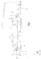
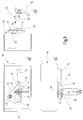
- the device shown in the drawing essentially comprises a on a chassis of a work machine such as a truck-mounted concrete pump or the like.
- the Rastund Guide member 12 in turn consists essentially of serving as a detent positions interruptions 16, 16 'having rail member 14 and two arranged in the end regions, partially in recesses 18, 18' of the rail member 14 engaging and pivotally mounted pawls 20, 20 '.
- a locking mechanism 24 is arranged with a locking bolt 26 which cooperates with the locking and guide member 12 such that the support member 10 can be locked in the final and intermediate positions with respect to the chassis of the machine.
- the structure and operation of the latch mechanism 24 is in the EP 0 633 847 B1 described in detail.
- the locking bolt 26 accordingly has three functional positions: a blocking position, an unlocking position and a release position.
- the locking bolt 26 In the locked position ( Fig. 2 . 3 . 9 and 10 ), the locking bolt 26 is pushed out of the latter by the action of a spring arranged in the housing 28 of the locking mechanism. As in Fig. 3b and 3c illustrated the locking bolt 26 then forms a stop for the front end surface of the rail member 14 (in both end positions of the support member) or the frontal boundary surfaces of the interruptions 16, 16 'of the rail element (in the two intermediate positions of the support member). The support member 10 is then blocked in its direction of displacement, ie locked with respect to the chassis of the driving machine.
- the latch bolt 26 is moved by manual operation of the lever 30 of the latch mechanism 24 by an operator against the spring force in its unlocked position ( Fig. 4 . 5 . 6 ), in which the locking bolt is pushed into the housing 28 and secured in this position, ie without external action remains the locking bolt 26 despite the action of the spring force in this position.
- the rail member 14 of the locking and guide member 12 is released in this position of the locking bolt 26, the support member can be seen in both directions (double arrow 32 in Fig. 1 and 2 ) are moved.
- the pawl 20 has a projecting over the rail element block portion 34, against which the locking bolt 26 is not free.
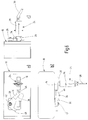
- the support member is now in the in Fig. 6
- the operator now has the choice of fully extend the support member 10 or to cause a lock in an intermediate position.
- a manual operation of the locking mechanism 24 is required, by which the locking bolt 26 is brought from the unlocked position into the blocking position.
- the locking bolt 26 is then partially pushed out of the housing 28 under the action of the spring force on the surface of the rail element 14 facing it.
- the rail member 14 slides under the latch bolt 26 up to the break 16 or 16 '(depending on which extension position of the support member 10 the operator has actuated the latch mechanism 24).
- the locking bolt 26 is aligned with the interruption 16 or 16 ', the locking bolt is displaced by the spring in its fully out of the housing 28 pushed out locking position and locks into the interruption 16 or 16' a.
- the support member 10 is locked in this position, as in Fig. 10 shown.
- the operator omits a manual operation of the latch mechanism 24.
- the pawls 20, 20 ' are mirror-symmetrical to each other and the figures represent only that portion of the latching and guide member 12 having the pawl 20.
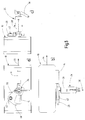
- the automatic release of the locking mechanism 24 is carried out according to the same principle.
- the locking bolt 26 then strikes first on the end region of the rail member 14 and slides on it until it reaches its end.
- the locking bolt 26 is then pushed by the spring out of the housing 28 into its locking position and the in Fig. 3 shown configuration in which the support member 10 is locked in its final position is reached again.
- the pawl In order to prevent that the pawl 20, 20 'by the locking bolt 26 or by external influences from its recess 18, 18' in the rail member 14 is pivoted out and thus could no longer act on the locking mechanism in the reverse direction, the pawl has a stop hook 48th on, which abuts against the free end face 50 of the rail element and limits the pivot angle of the pawl to less than 90 °. The pawl 20, 20 'is then in any case by the gravitational force in a position to take their operative position.
- the invention relates to a locking device for arranged on a driving or supporting frame and extendable from a retracted transport position in an extended working position, swing-out or telescoping support members 10 for a work machine, with a locking bolt 26 in a fixed to the frame, across Extraction of the support member 10 arranged guide bush between a blocking position and an unlocked position is displaced and biased under the action of a spring in the blocking position, with a locking bolt 26 between the locking position and the unlocked position sliding actuator 30, and with a rigidly arranged on the support member 10 latching - And guide member 12 for the locking bolt, wherein the locking and guide member 12 has a locking bolt 26 in a release position sliding guide 46 and wherein the locking bolt 26 in the release position automatically is movable in its blocking position.
- the locking and guide member 12 between a first detent position for the locking bolt 26 in the retracted transport position of the support member 10th and a second latching position for the latch bolt 26 in the region of the fully extended, swung or telescoped working position of the support member 10 extends, and that the locking and guide member 12 between the first and second latching position at least one further latching position 16, 16 'has.
Landscapes
- Engineering & Computer Science (AREA)
- Mechanical Engineering (AREA)
- Jib Cranes (AREA)
- Fittings On The Vehicle Exterior For Carrying Loads, And Devices For Holding Or Mounting Articles (AREA)
- Vehicle Cleaning, Maintenance, Repair, Refitting, And Outriggers (AREA)
- Lock And Its Accessories (AREA)
Claims (6)
- Dispositif de verrouillage pour des organes de support (10) pour un engin de travail, qui sont disposés sur un châssis ou sur un bâti porteur et qui peuvent se déployer, pivoter ou s'étendre d'une position de transport rentrée dans une position de travail sortie, avec un boulon de verrouillage (26), qui peut être déplacé entre une position de verrouillage et une position de déverrouillage dans une douille de guidage solidaire du châssis ou bâti et disposée transversalement à la direction de sortie de l'organe de support (10), et qui est précontraint sous l'action d'un ressort en direction de la position de verrouillage, avec un organe d'actionnement (30) déplaçant le boulon de verrouillage (26) entre la position de verrouillage et la position de déverrouillage, et avec un organe (12) d'enclenchement et de guidage pour le boulon de verrouillage, disposé rigidement sur l'organe de support (10), sachant que l'organe (12) d'enclenchement et de guidage présente une came de guidage (46) poussant le boulon de verrouillage (26) dans une position de libération et sachant que le boulon de verrouillage (26), lorsqu'il se trouve dans la position de libération, peut être déplacé automatiquement dans sa position de verrouillage, sachant que l'organe (12) d'enclenchement et de guidage s'étend entre une première position d'enclenchement pour le boulon de verrouillage (26) dans la région de la position de transport rentrée de l'organe de support (10) et une deuxième position d'enclenchement pour le boulon de verrouillage (26) dans la région de la position de travail entièrement déployée, pivotée ou étendue de l'organe de support (10), caractérisé en ce que l'organe (12) d'enclenchement et de guidage présente au moins une position d'enclenchement supplémentaire (16, 16') entre la première et la deuxième position d'enclenchement, et en ce que l'organe (12) d'enclenchement et de guidage présente respectivement dans la région de la première et de la deuxième position d'enclenchement un cliquet pivotant (20, 20') qui présente la came de guidage (46) agissant sur le boulon de verrouillage (26) dans une première direction de déplacement de l'organe de support (10) et déplaçant ce boulon de verrouillage entre sa position de déverrouillage et la position de libération.
- Dispositif selon la revendication 1, caractérisé en ce que le cliquet (20, 20') présente une surface de butée (38) pour le boulon de verrouillage (26), par laquelle le cliquet (20, 20') peut, dans une deuxième direction de déplacement de l'organe de support (10), être pivoté en dehors de la trajectoire de déplacement de l'organe de support sans pousser le boulon de verrouillage (26) dans sa position de libération.
- Dispositif selon la revendication 2, caractérisé en ce que le cliquet (20, 20') présente une partie de blocage (34) qui dépasse de l'organe (12) d'enclenchement et de guidage en direction du boulon de verrouillage (26) et sur laquelle sont disposées la came de guidage (46) et la surface de butée (38).
- Dispositif selon l'une des revendications 1 à 3, caractérisé en ce que l'organe (12) d'enclenchement et de guidage présente un élément formant rail (14) avec une surface de glissement pour le boulon de verrouillage (26) se trouvant dans la position de libération.
- Dispositif selon la revendication 4, caractérisé en ce que la position d'enclenchement supplémentaire au moins unique pour le boulon de verrouillage (26) est formée par une interruption (16, 16') dans l'élément formant rail (14).
- Dispositif selon l'une des revendications 1 à 5, caractérisé en ce que le cliquet (20, 20') présente un crochet de butée (48) qui vient buter contre une face frontale terminale (50) de l'élément formant rail (14) et qui limite l'angle de pivotement du cliquet (20, 20') à moins de 90°.
Applications Claiming Priority (2)
| Application Number | Priority Date | Filing Date | Title |
|---|---|---|---|
| DE201210215534 DE102012215534A1 (de) | 2012-08-31 | 2012-08-31 | Verriegelungsvorrichtung |
| PCT/EP2013/067370 WO2014033024A1 (fr) | 2012-08-31 | 2013-08-21 | Dispositif de verrouillage |
Publications (2)
| Publication Number | Publication Date |
|---|---|
| EP2890628A1 EP2890628A1 (fr) | 2015-07-08 |
| EP2890628B1 true EP2890628B1 (fr) | 2016-04-20 |
Family
ID=49080853
Family Applications (1)
| Application Number | Title | Priority Date | Filing Date |
|---|---|---|---|
| EP13753607.4A Active EP2890628B1 (fr) | 2012-08-31 | 2013-08-21 | Dispositif de verrouillage |
Country Status (7)
| Country | Link |
|---|---|
| US (1) | US9371214B2 (fr) |
| EP (1) | EP2890628B1 (fr) |
| JP (1) | JP6310916B2 (fr) |
| KR (1) | KR101999419B1 (fr) |
| CN (1) | CN104884379B (fr) |
| DE (1) | DE102012215534A1 (fr) |
| WO (1) | WO2014033024A1 (fr) |
Families Citing this family (6)
| Publication number | Priority date | Publication date | Assignee | Title |
|---|---|---|---|---|
| DE102013206366A1 (de) * | 2013-04-11 | 2014-10-16 | Putzmeister Engineering Gmbh | Fahrbare Betonpumpe mit Verteilermast und Abstützvorrichtung |
| DE102013209878A1 (de) * | 2013-05-28 | 2014-12-04 | Putzmeister Engineering Gmbh | Arbeitsgerät mit an einem Drehkopf angeordneten Arbeitsausleger |
| US10543817B2 (en) | 2016-12-15 | 2020-01-28 | Schwing America, Inc. | Powered rear outrigger systems |
| WO2019031568A1 (fr) * | 2017-08-09 | 2019-02-14 | 株式会社タダノ | Dispositif stabilisateur |
| DE102021111242A1 (de) | 2021-04-30 | 2022-11-03 | Liebherr-Mischtechnik Gmbh | Abstützvorrichtung für eine Autobetonpumpe |
| EP4431440A1 (fr) * | 2023-03-15 | 2024-09-18 | Manitowoc Crane Group France SAS | Support de grue mobile doté d'un dispositif de blocage |
Family Cites Families (25)
| Publication number | Priority date | Publication date | Assignee | Title |
|---|---|---|---|---|
| US3279622A (en) * | 1964-10-27 | 1966-10-18 | Edgar L Person | Vehicle stabilizing means |
| JPS56119755U (fr) | 1980-02-16 | 1981-09-11 | ||
| JPS641891Y2 (fr) * | 1980-10-29 | 1989-01-17 | ||
| US4394913A (en) | 1980-11-07 | 1983-07-26 | Harnischfeger Corporation | Crane having power operated outriggers and lock means therefor |
| JPS60130287U (ja) * | 1984-02-10 | 1985-08-31 | 株式会社タダノ | アウトリガ装置における可動部の固定装置の自動解除装置 |
| DE3830315A1 (de) | 1988-09-07 | 1990-03-08 | Putzmeister Maschf | Fahrbare betonpumpe |
| SE466593B (sv) * | 1990-05-04 | 1992-03-09 | Arne Henriksson Utveckling Kom | Anordning vid vaexelflak |
| JP2571062Y2 (ja) * | 1992-02-07 | 1998-05-13 | 株式会社加藤製作所 | アウトリガの自動ロツク装置 |
| DE4211493A1 (de) | 1992-04-06 | 1993-10-07 | Putzmeister Maschf | Verriegelungsvorrichtung für ausziehbare Stützorgane |
| DE19519810C2 (de) * | 1995-05-31 | 1998-12-10 | Gerd Baer | Stützbeine für Wechselbehälter |
| US5758785A (en) * | 1995-06-22 | 1998-06-02 | Spinosa; Dominic | Lifting system |
| US6422603B2 (en) * | 1998-10-30 | 2002-07-23 | Andry Lagsdin | Stabilizer pad for vehicles |
| DE10112084A1 (de) * | 2001-03-12 | 2002-09-19 | Putzmeister Ag | Fahrbare Dickstoffpumpe mit Stützkonstruktion und luftgefederter Radachse |
| DE20120964U1 (de) * | 2001-12-27 | 2003-06-12 | Liebherr-Hydraulikbagger GmbH, 88457 Kirchdorf | Abstützvorrichtung für Baumaschinen wie Hydraulikbagger u.dgl. |
| CN2587836Y (zh) * | 2002-11-18 | 2003-11-26 | 徐州重型机械厂 | 汽车起重机摆动式支腿 |
| DE50300539D1 (de) * | 2003-02-14 | 2005-06-16 | Palfinger Ag Bergheim | Transportsicherung |
| DE102005007522A1 (de) * | 2005-02-17 | 2006-08-31 | Putzmeister Ag | Stützausleger für fahrbare Arbeitsmaschinen |
| DE102006031257A1 (de) | 2006-07-06 | 2008-01-10 | Putzmeister Ag | Autobetonpumpe mit Knickmast |
| CN201511943U (zh) * | 2009-09-17 | 2010-06-23 | 徐州重型机械有限公司 | 工程机械及其支腿锁定装置 |
| CN201580365U (zh) * | 2009-11-30 | 2010-09-15 | 徐州重型机械有限公司 | 移动式工程机械及其支腿锁定机构 |
| CN102079297B (zh) * | 2009-11-30 | 2012-09-05 | 徐州重型机械有限公司 | 移动式工程机械及其支腿锁定机构 |
| KR101173284B1 (ko) * | 2010-07-07 | 2012-08-10 | 주식회사 에버다임 | 로킹장치 |
| CN201925264U (zh) * | 2010-12-01 | 2011-08-10 | 安徽星马汽车股份有限公司 | 混凝土泵车水平液压支腿的自动锁紧装置 |
| CN102060244B (zh) * | 2010-12-15 | 2012-09-05 | 徐州重型机械有限公司 | 起重机及其支腿定位装置 |
| CN202243396U (zh) * | 2011-09-30 | 2012-05-30 | 三一重工股份有限公司 | 一种支腿锁定装置及工程机械 |
-
2012
- 2012-08-31 DE DE201210215534 patent/DE102012215534A1/de not_active Withdrawn
-
2013
- 2013-08-21 CN CN201380037108.1A patent/CN104884379B/zh active Active
- 2013-08-21 KR KR1020157004550A patent/KR101999419B1/ko active Active
- 2013-08-21 US US14/402,399 patent/US9371214B2/en active Active
- 2013-08-21 JP JP2015528961A patent/JP6310916B2/ja active Active
- 2013-08-21 WO PCT/EP2013/067370 patent/WO2014033024A1/fr not_active Ceased
- 2013-08-21 EP EP13753607.4A patent/EP2890628B1/fr active Active
Also Published As
| Publication number | Publication date |
|---|---|
| JP2015533703A (ja) | 2015-11-26 |
| EP2890628A1 (fr) | 2015-07-08 |
| CN104884379A (zh) | 2015-09-02 |
| KR20150048731A (ko) | 2015-05-07 |
| DE102012215534A1 (de) | 2014-03-06 |
| CN104884379B (zh) | 2016-10-26 |
| US20150110544A1 (en) | 2015-04-23 |
| WO2014033024A1 (fr) | 2014-03-06 |
| US9371214B2 (en) | 2016-06-21 |
| JP6310916B2 (ja) | 2018-04-11 |
| KR101999419B1 (ko) | 2019-07-11 |
Similar Documents
| Publication | Publication Date | Title |
|---|---|---|
| EP3827146B1 (fr) | Mécanisme de levage pour système grimpant guidé sur des rails et procede de levage d'un système grimpant | |
| EP2890628B1 (fr) | Dispositif de verrouillage | |
| EP0681635B1 (fr) | Dispositif grimpeur, notamment pour echafaudage grimpant | |
| WO2017081021A1 (fr) | Grue mobile et procédé pour permettre un déplacement angulaire d'une rallonge de flèche principale par rapport à une flèche principale d'une grue mobile | |
| DE2756370A1 (de) | Kombinierter greifer in einem kernreaktor | |
| EP4351925A1 (fr) | Verrou abaissable pour conteneur | |
| EP2890627B1 (fr) | Dispositif de verrouillage | |
| DE102011116083B4 (de) | Sicherungs- und Verriegelungseinheit für Ausleger mit teleskopierbaren Schüssen, insbesondere bei Mobilkranen | |
| DE102012002122B4 (de) | Verriegelungsvorrichtung für einen Teleskopausleger | |
| EP2754800B1 (fr) | Gâche ou serrure à mortaiser | |
| EP3159452B1 (fr) | Chargeur frontal | |
| DE20120964U1 (de) | Abstützvorrichtung für Baumaschinen wie Hydraulikbagger u.dgl. | |
| DE102014019815B3 (de) | Formsteinverlegevorrichtung mit längenveränderbarem Verschiebeelement | |
| DE102014010265B4 (de) | Riegelwerk für Wertbehältnisse | |
| DE102005029652A1 (de) | Basketball-Korbanlage | |
| WO2016071202A1 (fr) | Serrure | |
| DE102010015477B4 (de) | Gerüstaufzug | |
| DE112021007801B4 (de) | Mehrfachteleskop | |
| EP1293611A1 (fr) | Chargeur frontal | |
| EP4267815B1 (fr) | Un système d'escalade guidé sur rails | |
| EP3018270B1 (fr) | Serrure | |
| EP4450447A1 (fr) | Support de grue mobile doté d'un dispositif de blocage | |
| EP2927397B1 (fr) | Serrure à mortaiser | |
| DE2450058C2 (de) | Vorrichtung zum abstellen mehrerer fahrzeuge uebereinander | |
| DE202016103040U1 (de) | Möbel mit Auszug |
Legal Events
| Date | Code | Title | Description |
|---|---|---|---|
| PUAI | Public reference made under article 153(3) epc to a published international application that has entered the european phase |
Free format text: ORIGINAL CODE: 0009012 |
|
| 17P | Request for examination filed |
Effective date: 20141027 |
|
| AK | Designated contracting states |
Kind code of ref document: A1 Designated state(s): AL AT BE BG CH CY CZ DE DK EE ES FI FR GB GR HR HU IE IS IT LI LT LU LV MC MK MT NL NO PL PT RO RS SE SI SK SM TR |
|
| AX | Request for extension of the european patent |
Extension state: BA ME |
|
| DAX | Request for extension of the european patent (deleted) | ||
| GRAP | Despatch of communication of intention to grant a patent |
Free format text: ORIGINAL CODE: EPIDOSNIGR1 |
|
| INTG | Intention to grant announced |
Effective date: 20160129 |
|
| GRAS | Grant fee paid |
Free format text: ORIGINAL CODE: EPIDOSNIGR3 |
|
| GRAA | (expected) grant |
Free format text: ORIGINAL CODE: 0009210 |
|
| AK | Designated contracting states |
Kind code of ref document: B1 Designated state(s): AL AT BE BG CH CY CZ DE DK EE ES FI FR GB GR HR HU IE IS IT LI LT LU LV MC MK MT NL NO PL PT RO RS SE SI SK SM TR |
|
| REG | Reference to a national code |
Ref country code: GB Ref legal event code: FG4D Free format text: NOT ENGLISH |
|
| REG | Reference to a national code |
Ref country code: CH Ref legal event code: EP |
|
| REG | Reference to a national code |
Ref country code: AT Ref legal event code: REF Ref document number: 792214 Country of ref document: AT Kind code of ref document: T Effective date: 20160515 |
|
| REG | Reference to a national code |
Ref country code: IE Ref legal event code: FG4D Free format text: LANGUAGE OF EP DOCUMENT: GERMAN |
|
| REG | Reference to a national code |
Ref country code: DE Ref legal event code: R096 Ref document number: 502013002694 Country of ref document: DE |
|
| REG | Reference to a national code |
Ref country code: LT Ref legal event code: MG4D |
|
| REG | Reference to a national code |
Ref country code: NL Ref legal event code: MP Effective date: 20160420 |
|
| PG25 | Lapsed in a contracting state [announced via postgrant information from national office to epo] |
Ref country code: PL Free format text: LAPSE BECAUSE OF FAILURE TO SUBMIT A TRANSLATION OF THE DESCRIPTION OR TO PAY THE FEE WITHIN THE PRESCRIBED TIME-LIMIT Effective date: 20160420 Ref country code: NL Free format text: LAPSE BECAUSE OF FAILURE TO SUBMIT A TRANSLATION OF THE DESCRIPTION OR TO PAY THE FEE WITHIN THE PRESCRIBED TIME-LIMIT Effective date: 20160420 Ref country code: LT Free format text: LAPSE BECAUSE OF FAILURE TO SUBMIT A TRANSLATION OF THE DESCRIPTION OR TO PAY THE FEE WITHIN THE PRESCRIBED TIME-LIMIT Effective date: 20160420 Ref country code: NO Free format text: LAPSE BECAUSE OF FAILURE TO SUBMIT A TRANSLATION OF THE DESCRIPTION OR TO PAY THE FEE WITHIN THE PRESCRIBED TIME-LIMIT Effective date: 20160720 Ref country code: FI Free format text: LAPSE BECAUSE OF FAILURE TO SUBMIT A TRANSLATION OF THE DESCRIPTION OR TO PAY THE FEE WITHIN THE PRESCRIBED TIME-LIMIT Effective date: 20160420 |
|
| PG25 | Lapsed in a contracting state [announced via postgrant information from national office to epo] |
Ref country code: SE Free format text: LAPSE BECAUSE OF FAILURE TO SUBMIT A TRANSLATION OF THE DESCRIPTION OR TO PAY THE FEE WITHIN THE PRESCRIBED TIME-LIMIT Effective date: 20160420 Ref country code: HR Free format text: LAPSE BECAUSE OF FAILURE TO SUBMIT A TRANSLATION OF THE DESCRIPTION OR TO PAY THE FEE WITHIN THE PRESCRIBED TIME-LIMIT Effective date: 20160420 Ref country code: ES Free format text: LAPSE BECAUSE OF FAILURE TO SUBMIT A TRANSLATION OF THE DESCRIPTION OR TO PAY THE FEE WITHIN THE PRESCRIBED TIME-LIMIT Effective date: 20160420 Ref country code: GR Free format text: LAPSE BECAUSE OF FAILURE TO SUBMIT A TRANSLATION OF THE DESCRIPTION OR TO PAY THE FEE WITHIN THE PRESCRIBED TIME-LIMIT Effective date: 20160721 Ref country code: PT Free format text: LAPSE BECAUSE OF FAILURE TO SUBMIT A TRANSLATION OF THE DESCRIPTION OR TO PAY THE FEE WITHIN THE PRESCRIBED TIME-LIMIT Effective date: 20160822 Ref country code: LV Free format text: LAPSE BECAUSE OF FAILURE TO SUBMIT A TRANSLATION OF THE DESCRIPTION OR TO PAY THE FEE WITHIN THE PRESCRIBED TIME-LIMIT Effective date: 20160420 Ref country code: RS Free format text: LAPSE BECAUSE OF FAILURE TO SUBMIT A TRANSLATION OF THE DESCRIPTION OR TO PAY THE FEE WITHIN THE PRESCRIBED TIME-LIMIT Effective date: 20160420 |
|
| PG25 | Lapsed in a contracting state [announced via postgrant information from national office to epo] |
Ref country code: BE Free format text: LAPSE BECAUSE OF NON-PAYMENT OF DUE FEES Effective date: 20160831 |
|
| REG | Reference to a national code |
Ref country code: DE Ref legal event code: R097 Ref document number: 502013002694 Country of ref document: DE |
|
| PG25 | Lapsed in a contracting state [announced via postgrant information from national office to epo] |
Ref country code: CZ Free format text: LAPSE BECAUSE OF FAILURE TO SUBMIT A TRANSLATION OF THE DESCRIPTION OR TO PAY THE FEE WITHIN THE PRESCRIBED TIME-LIMIT Effective date: 20160420 Ref country code: RO Free format text: LAPSE BECAUSE OF FAILURE TO SUBMIT A TRANSLATION OF THE DESCRIPTION OR TO PAY THE FEE WITHIN THE PRESCRIBED TIME-LIMIT Effective date: 20160420 Ref country code: SK Free format text: LAPSE BECAUSE OF FAILURE TO SUBMIT A TRANSLATION OF THE DESCRIPTION OR TO PAY THE FEE WITHIN THE PRESCRIBED TIME-LIMIT Effective date: 20160420 Ref country code: DK Free format text: LAPSE BECAUSE OF FAILURE TO SUBMIT A TRANSLATION OF THE DESCRIPTION OR TO PAY THE FEE WITHIN THE PRESCRIBED TIME-LIMIT Effective date: 20160420 Ref country code: EE Free format text: LAPSE BECAUSE OF FAILURE TO SUBMIT A TRANSLATION OF THE DESCRIPTION OR TO PAY THE FEE WITHIN THE PRESCRIBED TIME-LIMIT Effective date: 20160420 |
|
| PLBE | No opposition filed within time limit |
Free format text: ORIGINAL CODE: 0009261 |
|
| STAA | Information on the status of an ep patent application or granted ep patent |
Free format text: STATUS: NO OPPOSITION FILED WITHIN TIME LIMIT |
|
| PG25 | Lapsed in a contracting state [announced via postgrant information from national office to epo] |
Ref country code: SM Free format text: LAPSE BECAUSE OF FAILURE TO SUBMIT A TRANSLATION OF THE DESCRIPTION OR TO PAY THE FEE WITHIN THE PRESCRIBED TIME-LIMIT Effective date: 20160420 |
|
| 26N | No opposition filed |
Effective date: 20170123 |
|
| PG25 | Lapsed in a contracting state [announced via postgrant information from national office to epo] |
Ref country code: MC Free format text: LAPSE BECAUSE OF FAILURE TO SUBMIT A TRANSLATION OF THE DESCRIPTION OR TO PAY THE FEE WITHIN THE PRESCRIBED TIME-LIMIT Effective date: 20160420 |
|
| REG | Reference to a national code |
Ref country code: CH Ref legal event code: PL |
|
| PG25 | Lapsed in a contracting state [announced via postgrant information from national office to epo] |
Ref country code: CH Free format text: LAPSE BECAUSE OF NON-PAYMENT OF DUE FEES Effective date: 20160831 Ref country code: LI Free format text: LAPSE BECAUSE OF NON-PAYMENT OF DUE FEES Effective date: 20160831 |
|
| REG | Reference to a national code |
Ref country code: FR Ref legal event code: ST Effective date: 20170428 |
|
| PG25 | Lapsed in a contracting state [announced via postgrant information from national office to epo] |
Ref country code: SI Free format text: LAPSE BECAUSE OF FAILURE TO SUBMIT A TRANSLATION OF THE DESCRIPTION OR TO PAY THE FEE WITHIN THE PRESCRIBED TIME-LIMIT Effective date: 20160420 |
|
| REG | Reference to a national code |
Ref country code: IE Ref legal event code: MM4A |
|
| PG25 | Lapsed in a contracting state [announced via postgrant information from national office to epo] |
Ref country code: FR Free format text: LAPSE BECAUSE OF NON-PAYMENT OF DUE FEES Effective date: 20160831 Ref country code: IE Free format text: LAPSE BECAUSE OF NON-PAYMENT OF DUE FEES Effective date: 20160821 |
|
| PG25 | Lapsed in a contracting state [announced via postgrant information from national office to epo] |
Ref country code: LU Free format text: LAPSE BECAUSE OF NON-PAYMENT OF DUE FEES Effective date: 20160821 |
|
| GBPC | Gb: european patent ceased through non-payment of renewal fee |
Effective date: 20170821 |
|
| PG25 | Lapsed in a contracting state [announced via postgrant information from national office to epo] |
Ref country code: HU Free format text: LAPSE BECAUSE OF FAILURE TO SUBMIT A TRANSLATION OF THE DESCRIPTION OR TO PAY THE FEE WITHIN THE PRESCRIBED TIME-LIMIT; INVALID AB INITIO Effective date: 20130821 |
|
| PG25 | Lapsed in a contracting state [announced via postgrant information from national office to epo] |
Ref country code: CY Free format text: LAPSE BECAUSE OF FAILURE TO SUBMIT A TRANSLATION OF THE DESCRIPTION OR TO PAY THE FEE WITHIN THE PRESCRIBED TIME-LIMIT Effective date: 20160420 Ref country code: MK Free format text: LAPSE BECAUSE OF FAILURE TO SUBMIT A TRANSLATION OF THE DESCRIPTION OR TO PAY THE FEE WITHIN THE PRESCRIBED TIME-LIMIT Effective date: 20160420 Ref country code: IS Free format text: LAPSE BECAUSE OF FAILURE TO SUBMIT A TRANSLATION OF THE DESCRIPTION OR TO PAY THE FEE WITHIN THE PRESCRIBED TIME-LIMIT Effective date: 20160420 Ref country code: MT Free format text: LAPSE BECAUSE OF FAILURE TO SUBMIT A TRANSLATION OF THE DESCRIPTION OR TO PAY THE FEE WITHIN THE PRESCRIBED TIME-LIMIT Effective date: 20160420 |
|
| PG25 | Lapsed in a contracting state [announced via postgrant information from national office to epo] |
Ref country code: BG Free format text: LAPSE BECAUSE OF FAILURE TO SUBMIT A TRANSLATION OF THE DESCRIPTION OR TO PAY THE FEE WITHIN THE PRESCRIBED TIME-LIMIT Effective date: 20160420 Ref country code: GB Free format text: LAPSE BECAUSE OF NON-PAYMENT OF DUE FEES Effective date: 20170821 |
|
| PG25 | Lapsed in a contracting state [announced via postgrant information from national office to epo] |
Ref country code: AL Free format text: LAPSE BECAUSE OF FAILURE TO SUBMIT A TRANSLATION OF THE DESCRIPTION OR TO PAY THE FEE WITHIN THE PRESCRIBED TIME-LIMIT Effective date: 20160420 |
|
| REG | Reference to a national code |
Ref country code: AT Ref legal event code: MM01 Ref document number: 792214 Country of ref document: AT Kind code of ref document: T Effective date: 20180821 |
|
| PG25 | Lapsed in a contracting state [announced via postgrant information from national office to epo] |
Ref country code: AT Free format text: LAPSE BECAUSE OF NON-PAYMENT OF DUE FEES Effective date: 20180821 |
|
| PGFP | Annual fee paid to national office [announced via postgrant information from national office to epo] |
Ref country code: DE Payment date: 20250820 Year of fee payment: 13 |
|
| PGFP | Annual fee paid to national office [announced via postgrant information from national office to epo] |
Ref country code: TR Payment date: 20250812 Year of fee payment: 13 Ref country code: IT Payment date: 20250820 Year of fee payment: 13 |