EP2885108B1 - Hubvorrichtung mit kniehebelgetriebe - Google Patents
Hubvorrichtung mit kniehebelgetriebe Download PDFInfo
- Publication number
- EP2885108B1 EP2885108B1 EP13731337.5A EP13731337A EP2885108B1 EP 2885108 B1 EP2885108 B1 EP 2885108B1 EP 13731337 A EP13731337 A EP 13731337A EP 2885108 B1 EP2885108 B1 EP 2885108B1
- Authority
- EP
- European Patent Office
- Prior art keywords
- lifting
- drive
- positioning
- lifting part
- working position
- Prior art date
- Legal status (The legal status is an assumption and is not a legal conclusion. Google has not performed a legal analysis and makes no representation as to the accuracy of the status listed.)
- Active
Links
Images


Classifications
-
- B—PERFORMING OPERATIONS; TRANSPORTING
- B23—MACHINE TOOLS; METAL-WORKING NOT OTHERWISE PROVIDED FOR
- B23Q—DETAILS, COMPONENTS, OR ACCESSORIES FOR MACHINE TOOLS, e.g. ARRANGEMENTS FOR COPYING OR CONTROLLING; MACHINE TOOLS IN GENERAL CHARACTERISED BY THE CONSTRUCTION OF PARTICULAR DETAILS OR COMPONENTS; COMBINATIONS OR ASSOCIATIONS OF METAL-WORKING MACHINES, NOT DIRECTED TO A PARTICULAR RESULT
- B23Q7/00—Arrangements for handling work specially combined with or arranged in, or specially adapted for use in connection with, machine tools, e.g. for conveying, loading, positioning, discharging, sorting
- B23Q7/005—Lifting devices
-
- B—PERFORMING OPERATIONS; TRANSPORTING
- B23—MACHINE TOOLS; METAL-WORKING NOT OTHERWISE PROVIDED FOR
- B23Q—DETAILS, COMPONENTS, OR ACCESSORIES FOR MACHINE TOOLS, e.g. ARRANGEMENTS FOR COPYING OR CONTROLLING; MACHINE TOOLS IN GENERAL CHARACTERISED BY THE CONSTRUCTION OF PARTICULAR DETAILS OR COMPONENTS; COMBINATIONS OR ASSOCIATIONS OF METAL-WORKING MACHINES, NOT DIRECTED TO A PARTICULAR RESULT
- B23Q1/00—Members which are comprised in the general build-up of a form of machine, particularly relatively large fixed members
- B23Q1/25—Movable or adjustable work or tool supports
-
- B—PERFORMING OPERATIONS; TRANSPORTING
- B23—MACHINE TOOLS; METAL-WORKING NOT OTHERWISE PROVIDED FOR
- B23Q—DETAILS, COMPONENTS, OR ACCESSORIES FOR MACHINE TOOLS, e.g. ARRANGEMENTS FOR COPYING OR CONTROLLING; MACHINE TOOLS IN GENERAL CHARACTERISED BY THE CONSTRUCTION OF PARTICULAR DETAILS OR COMPONENTS; COMBINATIONS OR ASSOCIATIONS OF METAL-WORKING MACHINES, NOT DIRECTED TO A PARTICULAR RESULT
- B23Q16/00—Equipment for precise positioning of tool or work into particular locations not otherwise provided for
- B23Q16/001—Stops, cams, or holders therefor
Definitions
- the invention relates to a lifting device with a movable in the stroke direction between a working position and a rest position lifting part.
- a support unit and / or a clamping unit for supporting or for clamping a workpiece is arranged on the lifting part.
- the support unit may for example be a bezel for supporting a cylindrical workpiece.
- the clamping unit may for example have a tailstock or a similar clamping means to clamp a workpiece in particular axially.
- the lifting device is preferably for use in grinding machines when grinding cylindrical workpieces.
- a lift table is off DE 7016784 U1 known.
- the lifting table comprises a table top, a base part and a lever arrangement with four levers articulated to one another in a closed circle.
- One of the joints of the lever arrangement is arranged on the table top and the opposite joint on the base part.
- the other joints are free joints.
- At least one toggle mechanism is actuated by a drive to raise or lower the table top relative to the base part.
- a push rod of the drive connects the knee joint of the toggle mechanism with the free joints of the lever assembly.
- the drive is carried between the base part and the table top by the lever assembly and moved when moving the table top in the stroke direction. This is unfavorable because the mass of the drive must be completely moved. It has also been shown that the approach of the working position in such lifting tables for many applications is too inaccurate. Especially at the Support or when clamping workpieces in precision machines, the working position of the lifting part of the lifting device must be able to be set to a few micrometers accurate.
- EP 2 565 147 A1 describes a device for use with a lift. To cover bottom openings, there is a device in each floor opening which has a plate supported by a toggle mechanism. The plate covers the bottom opening and can be pressed by a large force of a lift against the biasing force of the toggle mechanism down into the bottom opening. A workpiece support is not described.
- Out DE 29 13 506 A1 is a lifting device with a movable in a lifting direction between a working position and a rest position Hubteil known.
- a drive device On a base part, a drive device is arranged which has a toggle mechanism and an expansion pin coupled to the toggle mechanism.
- the toggle mechanism has a first toggle lever pivotally connected to the lifting part and a second toggle lever pivotally connected to the base part, which are connected to one another at a knee joint.
- tension springs between the base part and the lifting part which act on the lifting part pulling in the rest position towards the base part.
- the lifting device has a drive unit arranged on a base part.
- To the drive means includes a coupled with a toggle gear drive.
- a first toggle lever of the toggle mechanism is on the lifting part and the other toggle lever of the toggle mechanism is hinged to the base part.
- the drive acts on the knee joint of the toggle mechanism.
- About a positioning the working position of the lifting part is specified.
- the positioning device defines the maximum distance between the lifting part and the base part, so that when moving the lifting part in the stroke direction away from the base part, the working position can be approached exactly.
- the positioning device relative to the toggle mechanism is adjusted or adjusted so that the toggle are out of their extended position when the lifting part has reached the working position.
- the extended position of the toggle lever is not reached during the entire movement between the rest position and the working position of the lifting part.
- the knee joint angle between the two toggle levers is in the rest position preferably 30 ° to 40 ° and in the working position preferably 170 ° to 178 °.
- the toggle lever of the toggle mechanism in the working position include a knee joint angle of less than 180 °, a sufficiently large force can be exerted on the lifting part in the stroke direction on the drive of the at least one drive means via the toggle mechanism so that it is pressed exactly into the position defined by the positioning device. In this way, the working position of the lifting part is achieved independently of a game in the drive device exactly.
- the toggle mechanism of the at least one drive device preferably consists of only two toggle levers, wherein each toggle lever in particular runs in a straight line between two bearing points.
- the toggle mechanism therefore preferably has only two additional bearings in addition to the knee joint.
- the positioning device has a lifting surface facing the stop surface, which rests in the working position on a contact surface of the lifting part.
- the positioning device has a column, which extends from the base part through a recess in the lifting part and carries at its end facing away from the base part a stop member with the stop surface.
- the stop surface and the contact surface come into contact only in the working position. Outside the working position, the positioning device preferably does not influence the position of the lifting part.
- the positioning and the lifting part are made in particular of steel.
- the working position can be defined very precisely.
- the positioning device has an adjusting device for adjusting the distance between the base part and the stop surface.
- the adjustment can have a differential screw.
- a differential screw for example, a stop member of the positioning, on which the stop surface is present is to be adjusted in the desired position relative to a column of the positioning device connected to the base part in the stroke direction.
- a clamping screw arranged transversely to the differential screw can serve, which acts on the differential screw and secures it against an accidental rotation.
- At least one positioning projection is provided on the abutment surface and / or on the abutment surface, which cooperates with an associated positioning indentation on the respective other surface.
- the positioning projection and / or the positioning recess may be prismatic in cross-section, for example triangular or trapezoidal.
- the contact surface and the abutment surface can be formed exclusively by the respective oblique surfaces of the at least one positioning projection or the respectively associated positioning recess.
- the at least one positioning projection engages in the respectively associated positioning recess when the lifting part is in its working position.
- the lifting part can be positioned transversely or radially to the lifting direction in an exact defined position relative to the positioning device.
- the drive means transverse to the stroke direction in the lifting part introduced forces can be supported by the positioning.
- a guide device for optionally displaceable guiding of the lifting part in the lifting direction therefore remains free of lateral force when the drive device presses the lifting part into the working position.
- the at least one positioning projection and the at least one associated positioning recess By means of the at least one positioning projection and the at least one associated positioning recess, play-free micrometer-accurate positioning of the lifting part in the working position can take place.
- the working position of the lifting part only the inclined surfaces of the at least one positioning projection of the stop surface and / or the contact surface abut against the associated inclined surfaces of the at least one positioning recess of the respective other surface.
- the working position of the lifting unit can be repeatedly approached to a micrometer.
- a plurality of drive means for example, two drive means may be present.
- Each of the drive devices has a drive and a toggle mechanism, wherein the drive means are basically the same structure.
- the toggle mechanisms of the two drive devices can be arranged, for example, on two opposite sides of the positioning device or the column of the positioning device. As a result, a good force distribution or force introduction can be achieved.
- the drives of the plurality of drive devices can be connected in parallel, so that the sum of the drive forces of all drives is transmitted via all toggle mechanism.
- the drive device may have either a controllable drive or a manually operated drive.
- the controllable drive has the advantage that the lifting part can be moved automatically between the rest position and the working position during operation of the machine tool or during machining of a workpiece.
- the controllable drive can be formed by a double-acting fluid cylinder.
- a pneumatic cylinder used.
- the piston rod of the fluid cylinder can act on the knee joint of the toggle mechanism.
- the cylinder housing of the fluid cylinder can be mounted pivotably on the base part.
- the speed of the lifting part decreases when the piston rod of the fluid cylinder is moved uniformly.
- one or more throttles may be disposed in the fluid lines connected to the fluid cylinder to limit the speed of movement of the piston rod. The control of the movement of the piston rod via the pressure to a fluid control unit, which is for example part of the machine control.
- the at least one drive means may further comprise a fluid control unit adapted to apply a fluid pressure to the fluid cylinder or the respective working chamber of a fluid cylinder even when the lift member is in the operative position or in the rest position. This ensures that the lifting part with a sufficiently large force held in the working position or the rest position and accurate positioning is achieved.
- the fluid control unit can be embodied as a common fluid control unit for all drive devices.
- the at least one drive device has a sensor unit for detecting the working position and / or the rest position.
- the double-acting fluid cylinder may have limit switches.
- the auxiliary drive in particular has a deformable body, which may be formed, for example, by a helical spring, a leaf spring, an elastomer body or the like.
- the deformable body for example the spring, is deformed and preferably compressed and therefore exerts an auxiliary force on the lifting part or an element connected to the lifting part.
- the auxiliary force acts or presses the lifting part out of the rest position in the lifting direction.
- the movement of the lifting part is supported from the rest position out.
- the lifting force caused by the at least one drive device in the stroke direction is small, so that a considerable total force would have to be generated by the drive of the drive device in order to achieve a sufficient lifting force.
- this can lead to undesirably large stresses.
- Such large total forces of the drive can be reduced by the provision of the auxiliary drive.
- the auxiliary power is provided not only in the rest position, but in any position of the lifting part.
- the auxiliary power may have the largest amount in the rest position and decrease with increasing distance or movement of the lifting part to the working position.
- the lifting part is guided linearly via a guide device in the stroke direction.
- the guide device may have one or more linear guide rails running in the stroke direction.
- the guide rails are preferably arranged on the drive device opposite side of the lifting part.
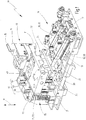
- a lifting device 10 is shown with a movable in a stroke direction H lifting part 11.
- the lifting part 11 is designed plate-shaped. It has a mounting surface 12 on which a support unit 13 - as in the embodiment shown here - and / or a clamping unit can be attached.
- the support unit 13 has a support member 14 with a support recess 15, which may be curved in cross section or prismatic. In the support recess 15, a workpiece not shown in detail in its axial extension direction can be partially encompassed and supported. In this way, axially clamped on one side in a chuck workpieces can be supported by the support unit 13 during machining at an axial distance from the chuck to avoid bending.
- a clamping unit with a tailstock or the like could be arranged on the lifting part 11.
- a free axial end of a workpiece can be clamped axially against a chuck via the clamping unit.
- the clamping unit can be mounted driveably or displaceably on the lifting part 11 transversely to the stroke direction H.
- the entire lifting device can also be displaceably mounted in a clamping direction.
- the lifting part 11 On the side opposite the mounting surface 12, the lifting part 11 has a drive side 16, which faces a base part 17.
- the base part 17 is executed in the embodiment as a base plate.
- At least one drive device 18 for moving the lifting part 11 in the stroke direction H is arranged on the base part 17.
- Each drive device 18 has a drive 19, which is formed by a double-acting fluid cylinder 20, for example.
- Each fluid cylinder 20 has two acted upon by compressed air working chambers, which are separated from each other by the piston fluidly. With the piston, a piston rod 21 is connected, which protrudes from the cylinder housing at one end.
- the free end of the piston rod 21 is coupled to a toggle mechanism 22 and, for example, acts on a knee joint 31 of the toggle mechanism 22.
- the fluid cylinder 20 can move the lifting part 11 in the stroke direction H by extending and retracting the piston rod 21 via the toggle mechanism.
- each fluid cylinder 20 has two fluid ports 23.
- the fluid connections are over in FIG. 3 schematically illustrated fluid lines 24 connected to a fluid control unit 25. Via the fluid control unit 25, fluid pressure is fed into one or the other working chamber of the double-acting fluid cylinder 20.
- the cylinder housing is pivotally mounted on the base part 17 at the end opposite the free end of the piston rod 21.
- hydraulic cylinders could alternatively be provided.
- drive 19 for the drive device 18 other controllable drives 19, for example, electric motors, linear motors or the like can serve as an alternative to the cylinders described here.
- a controllable drive 19 instead of a controllable drive 19 to provide a manually operated drive and to couple with the associated toggle mechanism 22. This can be, for example, an operating lever arrangement.
- a connecting piece 30 is present for this purpose, which connects the two free ends of the piston rods 21 with each other and is coupled to both knee joints 31 of the toggle mechanism.
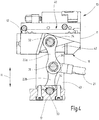
- the toggle mechanism 22 of a drive device 18 has a first toggle lever 22a hingedly connected to the lift member 11 and a second toggle lever 22b articulated to the base member 17.
- the two toggle levers 22a, 22b of a toggle mechanism 22 are articulated to each other at the knee joint 31.
- each toggle mechanism 22 has three bearings.
- For storage of the first knee lever 22a is a at least partially accessible from the drive side 16 of the lifting member 11 first axis 32 which is secured to the lifting part 11.
- the first axis 32 is preferably used for articulated mounting of both first toggle lever 22a of the two toggle mechanism 22.
- a second axis 33 is mounted on the base part 17 and accessible at least in sections.
- the second axis 33 serves in the embodiment for the articulated mounting of the two second toggle lever 22b on the base part 17.
- the three bearing points of the toggle mechanism 22 are in FIG. 4 illustrated.
- the toggle mechanism 22 has a needle bearing 34.
- the needle bearings 34 are sealed from the environment, for example, with radial shaft seals.
- the toggle levers 22a, 22b connect their two bearings in a straight line. They have a substantially bony shape.
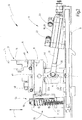
- the two drive devices 18 move the lifting part 11 between a rest position R (FIG. FIG. 3 ) and one Working position A ( FIG. 2 ).
- the lifting part 11 In the rest position R, the lifting part 11 has the smallest distance to the base part 17 and, for example, abuts the base part 17.
- the knee joint angle ⁇ formed between the two longitudinal axes of the toggle levers 22a, 22b is approximately 30 ° to 35 °.
- the longitudinal axis of the piston rod 21 forms in the rest position R, the bisector of the knee joint angle ⁇ .
- the piston rod 21 extends in the rest position R of the lifting part 11 approximately at right angles to the stroke direction H.
- the fluid cylinder 20 are pivotally mounted with its cylinder housing on the base part 17.
- the toggle levers 22a, 22b are aimed and the knee joint angle ⁇ enclosed between them becomes larger.
- the knee angle ⁇ has its maximum value and is smaller than 180 °.
- the knee joint angle ⁇ is always smaller than 180 ° in the entire range of movement of the lifting part 11 from the rest position R to the working position A.
- the knee joint angle ⁇ in the working position A is about 175 ° to 178 °.
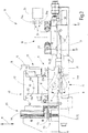
- the working position A of the lifting part 11 is predetermined by a positioning device 40.
- the positioning device 40 determines the maximum distance between the lifting part 11 and the base part 17th
- the positioning device has a lifting part 11 and according to the example the attachment surface 12 facing stop surface 41.
- the stop surface 41 is present in the embodiment of a stop member 42.
- the stopper 42 is disposed on a pillar 43 of the positioning device 40.
- the stop member 42 is adjustably mounted on the column 43 via an adjusting device 44 in the stroke direction H.
- adjusting 44 includes a in FIG. 7 shown differential screw 45.
- This differential screw 45 connects the stop member 42 with the column 43, so that a very accurate adjustment of the distance between the stop member with the stop surface 41 and the base member 17 is possible.
- the stop member 42 is guided in guide recesses 43 on the halls.
- To lock the adjusted position of the stop member 42 may serve a clamping screw which extends transversely to the stroke direction H and the position of the stop member 42 relative to the column 43 fixed, for example, in which it prevents an adjustment or rotation of the differential screw 45.
- FIG. 6 The representation in FIG. 6 is incomplete and does not show the stopper 42.
- the differential screw 45 and the pins 46 of the adjusting device 44 are in FIG. 7 shown.
- the stop member 42 has an extension of the column 43 extending parallelepiped portion 47.
- two cross members 48 extend transversely to the stroke direction H in opposite directions away from this cuboid section 47. This results in a total T-shaped shape of the stop member 42.
- At each cross member 48 is on the base part 17 or the lifting part 11 side facing a portion 41 a of the stop surface 41 is provided.
- the stop surface 41 is thus not contiguous, but consists of two spaced-apart portions 41 a, in each case a cross member 48th
- the lifting part 11 is an in FIG. 6 illustrated recess 50 available. Through this recess 50 protrudes in the rest position R, the column 43 and in the working position A of the rectangular portion 47 of the stop member 42 therethrough. In FIG. 6 is the column 43 and the stop member 42 is not shown for clarity.
- the column 43 and the rectangular portion 47 of the positioning device 40 are not used to guide the lifting member 11 in the stroke direction H, but only pass through the recess 50.
- Between the positioning device 40 and the lifting part 11 may be present in the region of the recess 50, a gap , so that in the rest position R of the lifting part 11 and during the movement of the lifting part 11 in the stroke direction H there is no guide contact between the positioning device 40 and the lifting part 11.
- a guide device 55 which has two parallel to each other in the stroke direction H extending guide rails 56 in the embodiment. These are encompassed by a firmly connected to the lifting part 11 guide member 57.
- the abutment surface 41 of the positioning device 40 and, according to the stopper part 42, is assigned a contact surface 60 on the lifting part 11, wherein the abutment surface 60 is formed by a portion of the attachment surface 12 in the exemplary embodiment.
- the contact surface 60 is particularly good in FIGS. 5 and 6 recognizable.
- the contact surface 60 also has two spaced apart surface portions 60a, which are each associated with a portion 41a of the stop surface 41.
- the lifting member 11 is in its working position A, the abutment surface 60 is located on the stop surface 41 at.
- neither the contact surface 60, nor the stop surface 41 are designed as flat surfaces, which would also be possible in a modification of the embodiment.
- the abutment surface 60 of the lifting part 11 is arranged on a plurality of positioning projections 61.
- Each positioning projection 61 is associated with a positioning recess 62, wherein the stop surface 41 is present at this positioning recesses 62. In the working position A of the lifting part 11, each positioning projection 61 engages in the associated positioning recess 62.
- the stop surface 41 provided either on Positioniervorsprüngen 61 or on Positioniervorsprüngen 61 and positioning recesses 62, wherein the abutment surface 60 may be formed corresponding to associated positioning recesses 62 or 62 and Positioniervertiefgen positioning projections 61.
- the positioning projections 61 have seen in cross-section a prismatic and, for example, a trapezoidal shape. They taper off the lifting part 11 away.
- the associated positioning recesses 62 have a cross-section adapted to the cross-sectional shape of the positioning projections 61, which in the embodiment is triangular in shape. Due to the triangular cross section of the positioning recesses 62 and the trapezoidal cross section the positioning protrusions 61 remains in the working position A of the lifting part 11 at the bottom of each positioning recess 62 a small clearance with respect to the engaging positioning projection 61, as shown in FIG FIG. 5 can be seen.
- the stop member 42 and the lifting member 11 abut each other only on the respective inclined surfaces of the positioning projections 61 and the positioning recesses 62, which thus form the stop surface 41 and the abutment surface 60.
- This configuration of the contact surface 60 and the stop surface 41 allows a very exact positioning of the lifting part 11 relative to the positioning device 40 and, according to the example, with respect to the stop part 42.
- the prism-shaped positioning projections 61 extend at right angles to the stroke direction H. At least one of the prism-shaped positioning projections 61 extends at right angles to the other positioning projections 61. As a result, the position of the lifting member 11 in the working position A is exactly radial to the stroke direction H by the positioning device 40 specified.
- each fluid cylinder 20 of the two drive devices 18 is subjected to a fluid pressure, so that via the piston rod 21 and the two toggle mechanism 22, the lifting member 11 is pressed with its contact surface 60 against the stop surface 41 of the positioning device 40.
- the forces acting on the lifting part 11 transverse forces transverse to the stroke direction H are supported by the positioning recesses 62 in the stop member 42 and thus do not act on the guide means 55.
- Both in the stroke direction H, as well as transversely to the stroke direction H is an exact positioning of the lifting member 11 in the Working position A reached. This working position A can with be approached very high accuracy.
- the support unit 13 arranged on the lifting part 11 always very accurately assumes the predetermined target position for supporting the associated workpiece.
- the lifting part 11 and therefore also the support unit 13 can be positioned on a micrometer exactly in the stroke direction H and transversely thereto.
- the working position A is predetermined by the positioning device 40 such that the two toggle levers 22a, 22b of a toggle mechanism 22 are outside their extended position, a sufficient force can be exerted on the lifting part 11 via the associated drive 19, with which the lifting part 11 is pressed in the working position A against the stop surface 41 of the positioning device 40. Since the knee joint angle ⁇ in the working position A is large in magnitude, sufficient for holding the lifting member 11 in the working position A usual pneumatic operating pressures in the range of 5 to 6 bar, as they are usually available in factories anyway.
- the lifting speed of the lifting part 11 is further limited by the fact that in the fluid lines 24 fluid throttles 24a are used ( FIG. 3 ).
- Each drive device 18 or at least one of the drive devices 18 may have a sensor unit 65 for detecting at least the working position A and the rest position R of the lifting part 11.
- the sensor unit 65 has two limit switches 66 in the relevant fluid cylinder 20, via which detects the position of the piston rod 21 and the piston mounted in the cylinder housing and therefore indirectly the working position A and the rest position R of the lifting part 11 can be determined.
- One of the limit switches 66 delivers upon reaching the working position A, a first sensor signal S1.
- the respective other limit switch 66 of the fluid cylinder 20 delivers a second sensor signal S2.
- the knee joint angle ⁇ is relatively small, so that the force acting on the knee joint 31 of the toggle mechanism 22 by the drive 19 generates only a small force component in the stroke direction H. This can lead to a relatively large driving force being required in order to be able to move the lifting part 11 out of the rest position R.
- an auxiliary drive 70 is present in the lifting device 10 described here.
- the auxiliary drive 70 provided an auxiliary force in the stroke direction H, which acts at least in the rest position R directly or indirectly on the lifting part 11.
- the auxiliary power of the auxiliary drive 70 therefore, the lifting movement of the lifting member 11 is supported from the rest position R out in the direction of the working position A.
- the auxiliary drive 70 has a deformable body 71, which is deformed in the rest position R and compressed according to the example, whereby he provides the auxiliary power in the stroke direction H in the rest position R.
- a deformable body 71 is used in the embodiment, a compression or coil spring 72 whose longitudinal axis extends in the stroke direction H.
- the pressure or coil spring 72 is arranged parallel to the guide rails 56 in the region of the guide device 55. Your one end is supported on the base part 17. The opposite end is located on a support member 73, which is fastened according to example directly on the lifting part 11. The force exerted by the compression or coil spring 72 spring force in the stroke direction H is thus on the support member 73 on the lifting part 11 a.
- the support member 73 is applied over the entire stroke of the lifting member 11 to the compression or coil spring 72.
- the spring force or auxiliary force in the stroke direction H therefore increases or decreases over the entire stroke of the lifting part 11. As a result, force jumps are avoided by the auxiliary drive 70 in the stroke direction H.
- the deformable body 71 could also be formed by a leaf spring or an elastomeric body. It would also be possible for the deformable body 71 to be in contact with the support part 73 or another element connected to the lift part 11 only at a certain knee-joint angle range starting from the rest position R. However, it can force jumps of the auxiliary force in the stroke direction H arise.
- the invention relates to a lifting device 10 with a lifting direction H between a rest position R and a working position A linearly movable lifting part 11.
- Das Hubteil 11 carries a support unit 13 for a workpiece and / or a clamping unit for this workpiece.
- At least one drive device 18 and in particular two drive devices 18 serve to move the lifting part 11.
- Each drive device 18 has a toggle mechanism 22, which has a first toggle lever 22a mounted pivotably on the lifting part 11 and a second toggle lever 22b mounted on a base part 17.
- the two toggle levers 22a, 22b are pivotally mounted to one another at a common knee joint 31. At the knee joint 32, a drive 19 of the drive unit 18 engages.
- a positioning device 40 specifies the position of the lifting part 11 in the stroke direction H and in particular also transversely to the stroke direction H in the working position A.
- it preferably has a stop surface 41, against which the lifting part 11 is pressed via the at least one drive means 18 in the working position A.
- this working position A of the knee joint angle ⁇ of the toggle mechanism 22 is smaller than 180 °, so that the two toggle levers 22a and 22b of the toggle mechanism 22 are outside the extended position.
Landscapes
- Engineering & Computer Science (AREA)
- Mechanical Engineering (AREA)
- Jigs For Machine Tools (AREA)
- Actuator (AREA)
- Machine Tool Units (AREA)
- Manipulator (AREA)
- Constituent Portions Of Griding Lathes, Driving, Sensing And Control (AREA)
Applications Claiming Priority (2)
| Application Number | Priority Date | Filing Date | Title |
|---|---|---|---|
| DE102012107611.1A DE102012107611A1 (de) | 2012-08-20 | 2012-08-20 | Hubvorrichtung mit Kniehebelgetriebe |
| PCT/EP2013/063246 WO2014029529A1 (de) | 2012-08-20 | 2013-06-25 | Hubvorrichtung mit kniehebelgetriebe |
Publications (2)
| Publication Number | Publication Date |
|---|---|
| EP2885108A1 EP2885108A1 (de) | 2015-06-24 |
| EP2885108B1 true EP2885108B1 (de) | 2017-10-11 |
Family
ID=48699029
Family Applications (1)
| Application Number | Title | Priority Date | Filing Date |
|---|---|---|---|
| EP13731337.5A Active EP2885108B1 (de) | 2012-08-20 | 2013-06-25 | Hubvorrichtung mit kniehebelgetriebe |
Country Status (9)
| Country | Link |
|---|---|
| US (1) | US9610666B2 (zh) |
| EP (1) | EP2885108B1 (zh) |
| JP (1) | JP6045701B2 (zh) |
| KR (1) | KR20150048787A (zh) |
| CN (1) | CN104718051B (zh) |
| AU (1) | AU2013304707B2 (zh) |
| DE (1) | DE102012107611A1 (zh) |
| HK (1) | HK1207335A1 (zh) |
| WO (1) | WO2014029529A1 (zh) |
Families Citing this family (4)
| Publication number | Priority date | Publication date | Assignee | Title |
|---|---|---|---|---|
| EP3456510B1 (en) * | 2017-09-19 | 2022-12-14 | CL Schutzrechtsverwaltungs GmbH | Apparatus for additively manufacturing of three-dimensional objects |
| AU2020253749A1 (en) * | 2019-04-05 | 2021-11-18 | Oshkosh Corporation | Battery management systems and methods |
| CN110682149B (zh) * | 2019-11-06 | 2020-08-18 | 徐州瑞益晟机械有限公司 | 一种建筑工程机械零部件的加工装置 |
| CN115284035B (zh) * | 2022-08-24 | 2023-07-14 | 常州机电职业技术学院 | 一种数控加工用的零件辅助定位装置及使用方法 |
Citations (1)
| Publication number | Priority date | Publication date | Assignee | Title |
|---|---|---|---|---|
| WO2004002872A1 (en) * | 2002-06-27 | 2004-01-08 | Jan Andersen | A stand for securing a two-wheeled vehicle, especially a motocross-motorcycle |
Family Cites Families (25)
| Publication number | Priority date | Publication date | Assignee | Title |
|---|---|---|---|---|
| US1393247A (en) * | 1920-02-18 | 1921-10-11 | Sauer John Geo | Lifting-jack |
| US2327368A (en) * | 1940-07-22 | 1943-08-24 | Olson John | Toggle pliers |
| US2483597A (en) * | 1946-03-22 | 1949-10-04 | Heppenstall Co | Supplemental forging press die |
| GB831541A (en) * | 1956-09-15 | 1960-03-30 | Hills & Sons Ltd F | An improved lift or hoist |
| US3226086A (en) * | 1964-01-08 | 1965-12-28 | Daniel C Lavieri | Power lift for trucks |
| US3642250A (en) * | 1969-12-16 | 1972-02-15 | Us Air Force | Bomblift trailer lifting mechanism |
| US3689058A (en) * | 1970-11-19 | 1972-09-05 | Gen Motors Corp | Toggle clamp |
| US3904853A (en) * | 1974-01-31 | 1975-09-09 | R F Shoup Corp | Stand for transporting and storing a machine |
| DE2526040A1 (de) * | 1975-06-11 | 1976-12-30 | Flodins Industri Ab | Anordnung bei bearbeitungsmaschinen |
| JPS5494700U (zh) | 1977-12-17 | 1979-07-04 | ||
| DE2913506A1 (de) * | 1979-04-04 | 1980-10-16 | Amsted Siemag Kette Gmbh | Kraftverstaerker |
| US4450935A (en) * | 1982-12-27 | 1984-05-29 | Gustavus David C | Portable adjustable roof platform |
| JPS6022210U (ja) | 1983-07-22 | 1985-02-15 | 住友重機械工業株式会社 | ドリル用定盤 |
| JPH0236655Y2 (zh) | 1985-04-12 | 1990-10-04 | ||
| JPH0634754Y2 (ja) | 1986-01-21 | 1994-09-14 | 株式会社オオヤマフ−ズマシナリ− | 油揚装置 |
| DE3604255A1 (de) * | 1986-02-11 | 1987-08-13 | Illig Maschinenbau Adolf | Kniehebelantrieb |
| US4879849A (en) | 1987-11-04 | 1989-11-14 | Omni Films International, Inc. | Point-of-view motion simulator system |
| DE8802326U1 (zh) * | 1988-02-23 | 1989-06-22 | Siemens Ag, 1000 Berlin Und 8000 Muenchen, De | |
| US5169112A (en) * | 1991-08-26 | 1992-12-08 | Milsco Manufacturing Company | Electronic suspension vehicle seat |
| JPH05237844A (ja) | 1992-02-28 | 1993-09-17 | Sintokogio Ltd | 金型クランプ装置 |
| JPH06263312A (ja) * | 1993-03-10 | 1994-09-20 | Aiseru Kk | 昇降ベッド駆動装置 |
| JP2000211897A (ja) * | 1999-01-21 | 2000-08-02 | Aichi Mach Ind Co Ltd | 無人搬送車のリフタ―機構 |
| JP4433941B2 (ja) | 2004-08-26 | 2010-03-17 | 株式会社ダイフク | 搬送装置 |
| JP4423606B2 (ja) | 2005-05-09 | 2010-03-03 | 新東工業株式会社 | 上・下鋳型の上・下鋳枠からの抜出し装置 |
| DE102011112206A1 (de) | 2011-09-02 | 2013-03-07 | Sherpa Autodiagnostik Gmbh | Überbrückung einer Bodenaussparung |
-
2012
- 2012-08-20 DE DE102012107611.1A patent/DE102012107611A1/de not_active Withdrawn
-
2013
- 2013-06-25 AU AU2013304707A patent/AU2013304707B2/en active Active
- 2013-06-25 CN CN201380054449.XA patent/CN104718051B/zh active Active
- 2013-06-25 KR KR1020157007033A patent/KR20150048787A/ko active IP Right Grant
- 2013-06-25 WO PCT/EP2013/063246 patent/WO2014029529A1/de active Application Filing
- 2013-06-25 EP EP13731337.5A patent/EP2885108B1/de active Active
- 2013-06-25 JP JP2015527815A patent/JP6045701B2/ja active Active
- 2013-06-25 US US14/422,966 patent/US9610666B2/en active Active
-
2015
- 2015-08-18 HK HK15107997.1A patent/HK1207335A1/zh unknown
Patent Citations (1)
| Publication number | Priority date | Publication date | Assignee | Title |
|---|---|---|---|---|
| WO2004002872A1 (en) * | 2002-06-27 | 2004-01-08 | Jan Andersen | A stand for securing a two-wheeled vehicle, especially a motocross-motorcycle |
Also Published As
| Publication number | Publication date |
|---|---|
| JP2015529573A (ja) | 2015-10-08 |
| WO2014029529A1 (de) | 2014-02-27 |
| US20150239085A1 (en) | 2015-08-27 |
| CN104718051B (zh) | 2017-08-25 |
| US9610666B2 (en) | 2017-04-04 |
| DE102012107611A1 (de) | 2014-05-15 |
| AU2013304707B2 (en) | 2016-06-09 |
| CN104718051A (zh) | 2015-06-17 |
| AU2013304707A1 (en) | 2015-04-09 |
| HK1207335A1 (zh) | 2016-01-29 |
| JP6045701B2 (ja) | 2016-12-14 |
| KR20150048787A (ko) | 2015-05-07 |
| EP2885108A1 (de) | 2015-06-24 |
Similar Documents
| Publication | Publication Date | Title |
|---|---|---|
| EP2197660B1 (de) | Schieberelement für einen Keiltrieb und Keiltrieb mit solchem Schieberelement | |
| EP2509725B1 (de) | Radialpresse | |
| AT503790B1 (de) | Anschlagvorrichtung für eine biegepresse | |
| EP3213833B1 (de) | Vorrichtung mit presse, werkzeug und werkzeugschutzsystem zur bearbeitung von blechwerkstücken | |
| EP2874804B1 (de) | Keiltrieb | |
| EP3393693B1 (de) | Keiltrieb | |
| EP2694230B1 (de) | Radialpresse | |
| EP2885108B1 (de) | Hubvorrichtung mit kniehebelgetriebe | |
| EP3093102A1 (de) | Lünette | |
| EP2887513B1 (de) | Linearmotoranordnung und Werkzeugmaschine mit einer Linearmotoranordnung | |
| EP3113891B1 (de) | Werkzeugschieber | |
| EP3113941B1 (de) | Werkzeugschieber | |
| EP3113892B1 (de) | Werkzeugschieber | |
| DE102011054063A1 (de) | Antriebsvorrichtung für ein Stützteil zum Abstützen eines Werkstücks | |
| EP3569354B1 (de) | Vorrichtung zur fixierung von werkstücken und bearbeitungsanlage. | |
| DE102014109144A1 (de) | Verbesserte C-Gestell-Presse | |
| EP2813723A2 (de) | Mit schräg angeordneter Abrollzone ausgestattete Brems- und/oder Klemmvorrichtung eines an mindestens einer Schiene geführten Schlittens | |
| DE2010389C3 (de) | Führungsanordnung mit einer Lagekorrektur-Regeleinrichtung zum Ausgleich von Lageabweichungen an einem geführten Maschinenteil bei Werkzeugmaschinen oder dgl | |
| EP2783795B1 (de) | Spannbacke | |
| EP3095534B1 (de) | Biegemaschine | |
| EP3536503B1 (de) | Klemmvorrichtung zur befestigung von druckplatten auf einem plattenzylinder einer druckmaschine | |
| WO2022112518A1 (de) | Höhenverstellbarer arbeitstisch | |
| DE2127249C3 (de) | Sicherheits-Spannschienenanordnung für Spannvorrichtungen an Koordinatentischen für Revolverstanzpressen | |
| DE2242593C3 (de) | Klemmeinrichtung für den Reitstock einer Werkzeugmaschine | |
| EP1344585A2 (de) | Hydroelastische Tiefzieheinrichtung |
Legal Events
| Date | Code | Title | Description |
|---|---|---|---|
| PUAI | Public reference made under article 153(3) epc to a published international application that has entered the european phase |
Free format text: ORIGINAL CODE: 0009012 |
|
| 17P | Request for examination filed |
Effective date: 20150319 |
|
| AK | Designated contracting states |
Kind code of ref document: A1 Designated state(s): AL AT BE BG CH CY CZ DE DK EE ES FI FR GB GR HR HU IE IS IT LI LT LU LV MC MK MT NL NO PL PT RO RS SE SI SK SM TR |
|
| AX | Request for extension of the european patent |
Extension state: BA ME |
|
| RIN1 | Information on inventor provided before grant (corrected) |
Inventor name: SCHINDLER, DANIEL Inventor name: KUEMMERLE, SIMON |
|
| DAX | Request for extension of the european patent (deleted) | ||
| REG | Reference to a national code |
Ref country code: HK Ref legal event code: DE Ref document number: 1207335 Country of ref document: HK |
|
| 17Q | First examination report despatched |
Effective date: 20160414 |
|
| GRAP | Despatch of communication of intention to grant a patent |
Free format text: ORIGINAL CODE: EPIDOSNIGR1 |
|
| STAA | Information on the status of an ep patent application or granted ep patent |
Free format text: STATUS: GRANT OF PATENT IS INTENDED |
|
| INTG | Intention to grant announced |
Effective date: 20170523 |
|
| GRAS | Grant fee paid |
Free format text: ORIGINAL CODE: EPIDOSNIGR3 |
|
| GRAA | (expected) grant |
Free format text: ORIGINAL CODE: 0009210 |
|
| STAA | Information on the status of an ep patent application or granted ep patent |
Free format text: STATUS: THE PATENT HAS BEEN GRANTED |
|
| AK | Designated contracting states |
Kind code of ref document: B1 Designated state(s): AL AT BE BG CH CY CZ DE DK EE ES FI FR GB GR HR HU IE IS IT LI LT LU LV MC MK MT NL NO PL PT RO RS SE SI SK SM TR |
|
| REG | Reference to a national code |
Ref country code: GB Ref legal event code: FG4D Free format text: NOT ENGLISH |
|
| REG | Reference to a national code |
Ref country code: CH Ref legal event code: EP |
|
| REG | Reference to a national code |
Ref country code: IE Ref legal event code: FG4D Free format text: LANGUAGE OF EP DOCUMENT: GERMAN |
|
| REG | Reference to a national code |
Ref country code: AT Ref legal event code: REF Ref document number: 935596 Country of ref document: AT Kind code of ref document: T Effective date: 20171115 |
|
| REG | Reference to a national code |
Ref country code: DE Ref legal event code: R096 Ref document number: 502013008557 Country of ref document: DE |
|
| REG | Reference to a national code |
Ref country code: SE Ref legal event code: TRGR |
|
| REG | Reference to a national code |
Ref country code: NL Ref legal event code: MP Effective date: 20171011 |
|
| REG | Reference to a national code |
Ref country code: LT Ref legal event code: MG4D |
|
| PG25 | Lapsed in a contracting state [announced via postgrant information from national office to epo] |
Ref country code: NL Free format text: LAPSE BECAUSE OF FAILURE TO SUBMIT A TRANSLATION OF THE DESCRIPTION OR TO PAY THE FEE WITHIN THE PRESCRIBED TIME-LIMIT Effective date: 20171011 |
|
| REG | Reference to a national code |
Ref country code: HK Ref legal event code: GR Ref document number: 1207335 Country of ref document: HK |
|
| PG25 | Lapsed in a contracting state [announced via postgrant information from national office to epo] |
Ref country code: LT Free format text: LAPSE BECAUSE OF FAILURE TO SUBMIT A TRANSLATION OF THE DESCRIPTION OR TO PAY THE FEE WITHIN THE PRESCRIBED TIME-LIMIT Effective date: 20171011 Ref country code: NO Free format text: LAPSE BECAUSE OF FAILURE TO SUBMIT A TRANSLATION OF THE DESCRIPTION OR TO PAY THE FEE WITHIN THE PRESCRIBED TIME-LIMIT Effective date: 20180111 Ref country code: FI Free format text: LAPSE BECAUSE OF FAILURE TO SUBMIT A TRANSLATION OF THE DESCRIPTION OR TO PAY THE FEE WITHIN THE PRESCRIBED TIME-LIMIT Effective date: 20171011 Ref country code: ES Free format text: LAPSE BECAUSE OF FAILURE TO SUBMIT A TRANSLATION OF THE DESCRIPTION OR TO PAY THE FEE WITHIN THE PRESCRIBED TIME-LIMIT Effective date: 20171011 |
|
| PG25 | Lapsed in a contracting state [announced via postgrant information from national office to epo] |
Ref country code: HR Free format text: LAPSE BECAUSE OF FAILURE TO SUBMIT A TRANSLATION OF THE DESCRIPTION OR TO PAY THE FEE WITHIN THE PRESCRIBED TIME-LIMIT Effective date: 20171011 Ref country code: GR Free format text: LAPSE BECAUSE OF FAILURE TO SUBMIT A TRANSLATION OF THE DESCRIPTION OR TO PAY THE FEE WITHIN THE PRESCRIBED TIME-LIMIT Effective date: 20180112 Ref country code: LV Free format text: LAPSE BECAUSE OF FAILURE TO SUBMIT A TRANSLATION OF THE DESCRIPTION OR TO PAY THE FEE WITHIN THE PRESCRIBED TIME-LIMIT Effective date: 20171011 Ref country code: RS Free format text: LAPSE BECAUSE OF FAILURE TO SUBMIT A TRANSLATION OF THE DESCRIPTION OR TO PAY THE FEE WITHIN THE PRESCRIBED TIME-LIMIT Effective date: 20171011 Ref country code: IS Free format text: LAPSE BECAUSE OF FAILURE TO SUBMIT A TRANSLATION OF THE DESCRIPTION OR TO PAY THE FEE WITHIN THE PRESCRIBED TIME-LIMIT Effective date: 20180211 Ref country code: BG Free format text: LAPSE BECAUSE OF FAILURE TO SUBMIT A TRANSLATION OF THE DESCRIPTION OR TO PAY THE FEE WITHIN THE PRESCRIBED TIME-LIMIT Effective date: 20180111 |
|
| REG | Reference to a national code |
Ref country code: DE Ref legal event code: R097 Ref document number: 502013008557 Country of ref document: DE |
|
| PG25 | Lapsed in a contracting state [announced via postgrant information from national office to epo] |
Ref country code: SK Free format text: LAPSE BECAUSE OF FAILURE TO SUBMIT A TRANSLATION OF THE DESCRIPTION OR TO PAY THE FEE WITHIN THE PRESCRIBED TIME-LIMIT Effective date: 20171011 Ref country code: CZ Free format text: LAPSE BECAUSE OF FAILURE TO SUBMIT A TRANSLATION OF THE DESCRIPTION OR TO PAY THE FEE WITHIN THE PRESCRIBED TIME-LIMIT Effective date: 20171011 Ref country code: DK Free format text: LAPSE BECAUSE OF FAILURE TO SUBMIT A TRANSLATION OF THE DESCRIPTION OR TO PAY THE FEE WITHIN THE PRESCRIBED TIME-LIMIT Effective date: 20171011 Ref country code: EE Free format text: LAPSE BECAUSE OF FAILURE TO SUBMIT A TRANSLATION OF THE DESCRIPTION OR TO PAY THE FEE WITHIN THE PRESCRIBED TIME-LIMIT Effective date: 20171011 |
|
| PLBE | No opposition filed within time limit |
Free format text: ORIGINAL CODE: 0009261 |
|
| STAA | Information on the status of an ep patent application or granted ep patent |
Free format text: STATUS: NO OPPOSITION FILED WITHIN TIME LIMIT |
|
| PG25 | Lapsed in a contracting state [announced via postgrant information from national office to epo] |
Ref country code: PL Free format text: LAPSE BECAUSE OF FAILURE TO SUBMIT A TRANSLATION OF THE DESCRIPTION OR TO PAY THE FEE WITHIN THE PRESCRIBED TIME-LIMIT Effective date: 20171011 Ref country code: RO Free format text: LAPSE BECAUSE OF FAILURE TO SUBMIT A TRANSLATION OF THE DESCRIPTION OR TO PAY THE FEE WITHIN THE PRESCRIBED TIME-LIMIT Effective date: 20171011 Ref country code: SM Free format text: LAPSE BECAUSE OF FAILURE TO SUBMIT A TRANSLATION OF THE DESCRIPTION OR TO PAY THE FEE WITHIN THE PRESCRIBED TIME-LIMIT Effective date: 20171011 |
|
| 26N | No opposition filed |
Effective date: 20180712 |
|
| PG25 | Lapsed in a contracting state [announced via postgrant information from national office to epo] |
Ref country code: MT Free format text: LAPSE BECAUSE OF FAILURE TO SUBMIT A TRANSLATION OF THE DESCRIPTION OR TO PAY THE FEE WITHIN THE PRESCRIBED TIME-LIMIT Effective date: 20171011 |
|
| PG25 | Lapsed in a contracting state [announced via postgrant information from national office to epo] |
Ref country code: SI Free format text: LAPSE BECAUSE OF FAILURE TO SUBMIT A TRANSLATION OF THE DESCRIPTION OR TO PAY THE FEE WITHIN THE PRESCRIBED TIME-LIMIT Effective date: 20171011 |
|
| REG | Reference to a national code |
Ref country code: BE Ref legal event code: MM Effective date: 20180630 |
|
| REG | Reference to a national code |
Ref country code: IE Ref legal event code: MM4A |
|
| PG25 | Lapsed in a contracting state [announced via postgrant information from national office to epo] |
Ref country code: MC Free format text: LAPSE BECAUSE OF FAILURE TO SUBMIT A TRANSLATION OF THE DESCRIPTION OR TO PAY THE FEE WITHIN THE PRESCRIBED TIME-LIMIT Effective date: 20171011 Ref country code: LU Free format text: LAPSE BECAUSE OF NON-PAYMENT OF DUE FEES Effective date: 20180625 |
|
| PG25 | Lapsed in a contracting state [announced via postgrant information from national office to epo] |
Ref country code: FR Free format text: LAPSE BECAUSE OF NON-PAYMENT OF DUE FEES Effective date: 20180630 Ref country code: IE Free format text: LAPSE BECAUSE OF NON-PAYMENT OF DUE FEES Effective date: 20180625 |
|
| PG25 | Lapsed in a contracting state [announced via postgrant information from national office to epo] |
Ref country code: BE Free format text: LAPSE BECAUSE OF NON-PAYMENT OF DUE FEES Effective date: 20180630 |
|
| REG | Reference to a national code |
Ref country code: AT Ref legal event code: MM01 Ref document number: 935596 Country of ref document: AT Kind code of ref document: T Effective date: 20180625 |
|
| PG25 | Lapsed in a contracting state [announced via postgrant information from national office to epo] |
Ref country code: AT Free format text: LAPSE BECAUSE OF NON-PAYMENT OF DUE FEES Effective date: 20180625 |
|
| PG25 | Lapsed in a contracting state [announced via postgrant information from national office to epo] |
Ref country code: TR Free format text: LAPSE BECAUSE OF FAILURE TO SUBMIT A TRANSLATION OF THE DESCRIPTION OR TO PAY THE FEE WITHIN THE PRESCRIBED TIME-LIMIT Effective date: 20171011 |
|
| PG25 | Lapsed in a contracting state [announced via postgrant information from national office to epo] |
Ref country code: PT Free format text: LAPSE BECAUSE OF FAILURE TO SUBMIT A TRANSLATION OF THE DESCRIPTION OR TO PAY THE FEE WITHIN THE PRESCRIBED TIME-LIMIT Effective date: 20171011 |
|
| PG25 | Lapsed in a contracting state [announced via postgrant information from national office to epo] |
Ref country code: CY Free format text: LAPSE BECAUSE OF FAILURE TO SUBMIT A TRANSLATION OF THE DESCRIPTION OR TO PAY THE FEE WITHIN THE PRESCRIBED TIME-LIMIT Effective date: 20171011 Ref country code: MK Free format text: LAPSE BECAUSE OF NON-PAYMENT OF DUE FEES Effective date: 20171011 Ref country code: HU Free format text: LAPSE BECAUSE OF FAILURE TO SUBMIT A TRANSLATION OF THE DESCRIPTION OR TO PAY THE FEE WITHIN THE PRESCRIBED TIME-LIMIT; INVALID AB INITIO Effective date: 20130625 |
|
| PG25 | Lapsed in a contracting state [announced via postgrant information from national office to epo] |
Ref country code: AL Free format text: LAPSE BECAUSE OF FAILURE TO SUBMIT A TRANSLATION OF THE DESCRIPTION OR TO PAY THE FEE WITHIN THE PRESCRIBED TIME-LIMIT Effective date: 20171011 |
|
| PGFP | Annual fee paid to national office [announced via postgrant information from national office to epo] |
Ref country code: DE Payment date: 20230530 Year of fee payment: 11 |
|
| PGFP | Annual fee paid to national office [announced via postgrant information from national office to epo] |
Ref country code: SE Payment date: 20230620 Year of fee payment: 11 |
|
| PGFP | Annual fee paid to national office [announced via postgrant information from national office to epo] |
Ref country code: IT Payment date: 20230623 Year of fee payment: 11 Ref country code: GB Payment date: 20230622 Year of fee payment: 11 Ref country code: CH Payment date: 20230702 Year of fee payment: 11 |