EP2885108B1 - Lifting apparatus having a toggle lever mechanism - Google Patents
Lifting apparatus having a toggle lever mechanism Download PDFInfo
- Publication number
- EP2885108B1 EP2885108B1 EP13731337.5A EP13731337A EP2885108B1 EP 2885108 B1 EP2885108 B1 EP 2885108B1 EP 13731337 A EP13731337 A EP 13731337A EP 2885108 B1 EP2885108 B1 EP 2885108B1
- Authority
- EP
- European Patent Office
- Prior art keywords
- lifting
- drive
- positioning
- lifting part
- working position
- Prior art date
- Legal status (The legal status is an assumption and is not a legal conclusion. Google has not performed a legal analysis and makes no representation as to the accuracy of the status listed.)
- Active
Links
Images


Classifications
-
- B—PERFORMING OPERATIONS; TRANSPORTING
- B23—MACHINE TOOLS; METAL-WORKING NOT OTHERWISE PROVIDED FOR
- B23Q—DETAILS, COMPONENTS, OR ACCESSORIES FOR MACHINE TOOLS, e.g. ARRANGEMENTS FOR COPYING OR CONTROLLING; MACHINE TOOLS IN GENERAL CHARACTERISED BY THE CONSTRUCTION OF PARTICULAR DETAILS OR COMPONENTS; COMBINATIONS OR ASSOCIATIONS OF METAL-WORKING MACHINES, NOT DIRECTED TO A PARTICULAR RESULT
- B23Q7/00—Arrangements for handling work specially combined with or arranged in, or specially adapted for use in connection with, machine tools, e.g. for conveying, loading, positioning, discharging, sorting
- B23Q7/005—Lifting devices
-
- B—PERFORMING OPERATIONS; TRANSPORTING
- B23—MACHINE TOOLS; METAL-WORKING NOT OTHERWISE PROVIDED FOR
- B23Q—DETAILS, COMPONENTS, OR ACCESSORIES FOR MACHINE TOOLS, e.g. ARRANGEMENTS FOR COPYING OR CONTROLLING; MACHINE TOOLS IN GENERAL CHARACTERISED BY THE CONSTRUCTION OF PARTICULAR DETAILS OR COMPONENTS; COMBINATIONS OR ASSOCIATIONS OF METAL-WORKING MACHINES, NOT DIRECTED TO A PARTICULAR RESULT
- B23Q1/00—Members which are comprised in the general build-up of a form of machine, particularly relatively large fixed members
- B23Q1/25—Movable or adjustable work or tool supports
-
- B—PERFORMING OPERATIONS; TRANSPORTING
- B23—MACHINE TOOLS; METAL-WORKING NOT OTHERWISE PROVIDED FOR
- B23Q—DETAILS, COMPONENTS, OR ACCESSORIES FOR MACHINE TOOLS, e.g. ARRANGEMENTS FOR COPYING OR CONTROLLING; MACHINE TOOLS IN GENERAL CHARACTERISED BY THE CONSTRUCTION OF PARTICULAR DETAILS OR COMPONENTS; COMBINATIONS OR ASSOCIATIONS OF METAL-WORKING MACHINES, NOT DIRECTED TO A PARTICULAR RESULT
- B23Q16/00—Equipment for precise positioning of tool or work into particular locations not otherwise provided for
- B23Q16/001—Stops, cams, or holders therefor
Definitions
- the invention relates to a lifting device with a movable in the stroke direction between a working position and a rest position lifting part.
- a support unit and / or a clamping unit for supporting or for clamping a workpiece is arranged on the lifting part.
- the support unit may for example be a bezel for supporting a cylindrical workpiece.
- the clamping unit may for example have a tailstock or a similar clamping means to clamp a workpiece in particular axially.
- the lifting device is preferably for use in grinding machines when grinding cylindrical workpieces.
- a lift table is off DE 7016784 U1 known.
- the lifting table comprises a table top, a base part and a lever arrangement with four levers articulated to one another in a closed circle.
- One of the joints of the lever arrangement is arranged on the table top and the opposite joint on the base part.
- the other joints are free joints.
- At least one toggle mechanism is actuated by a drive to raise or lower the table top relative to the base part.
- a push rod of the drive connects the knee joint of the toggle mechanism with the free joints of the lever assembly.
- the drive is carried between the base part and the table top by the lever assembly and moved when moving the table top in the stroke direction. This is unfavorable because the mass of the drive must be completely moved. It has also been shown that the approach of the working position in such lifting tables for many applications is too inaccurate. Especially at the Support or when clamping workpieces in precision machines, the working position of the lifting part of the lifting device must be able to be set to a few micrometers accurate.
- EP 2 565 147 A1 describes a device for use with a lift. To cover bottom openings, there is a device in each floor opening which has a plate supported by a toggle mechanism. The plate covers the bottom opening and can be pressed by a large force of a lift against the biasing force of the toggle mechanism down into the bottom opening. A workpiece support is not described.
- Out DE 29 13 506 A1 is a lifting device with a movable in a lifting direction between a working position and a rest position Hubteil known.
- a drive device On a base part, a drive device is arranged which has a toggle mechanism and an expansion pin coupled to the toggle mechanism.
- the toggle mechanism has a first toggle lever pivotally connected to the lifting part and a second toggle lever pivotally connected to the base part, which are connected to one another at a knee joint.
- tension springs between the base part and the lifting part which act on the lifting part pulling in the rest position towards the base part.
- the lifting device has a drive unit arranged on a base part.
- To the drive means includes a coupled with a toggle gear drive.
- a first toggle lever of the toggle mechanism is on the lifting part and the other toggle lever of the toggle mechanism is hinged to the base part.
- the drive acts on the knee joint of the toggle mechanism.
- About a positioning the working position of the lifting part is specified.
- the positioning device defines the maximum distance between the lifting part and the base part, so that when moving the lifting part in the stroke direction away from the base part, the working position can be approached exactly.
- the positioning device relative to the toggle mechanism is adjusted or adjusted so that the toggle are out of their extended position when the lifting part has reached the working position.
- the extended position of the toggle lever is not reached during the entire movement between the rest position and the working position of the lifting part.
- the knee joint angle between the two toggle levers is in the rest position preferably 30 ° to 40 ° and in the working position preferably 170 ° to 178 °.
- the toggle lever of the toggle mechanism in the working position include a knee joint angle of less than 180 °, a sufficiently large force can be exerted on the lifting part in the stroke direction on the drive of the at least one drive means via the toggle mechanism so that it is pressed exactly into the position defined by the positioning device. In this way, the working position of the lifting part is achieved independently of a game in the drive device exactly.
- the toggle mechanism of the at least one drive device preferably consists of only two toggle levers, wherein each toggle lever in particular runs in a straight line between two bearing points.
- the toggle mechanism therefore preferably has only two additional bearings in addition to the knee joint.
- the positioning device has a lifting surface facing the stop surface, which rests in the working position on a contact surface of the lifting part.
- the positioning device has a column, which extends from the base part through a recess in the lifting part and carries at its end facing away from the base part a stop member with the stop surface.
- the stop surface and the contact surface come into contact only in the working position. Outside the working position, the positioning device preferably does not influence the position of the lifting part.
- the positioning and the lifting part are made in particular of steel.
- the working position can be defined very precisely.
- the positioning device has an adjusting device for adjusting the distance between the base part and the stop surface.
- the adjustment can have a differential screw.
- a differential screw for example, a stop member of the positioning, on which the stop surface is present is to be adjusted in the desired position relative to a column of the positioning device connected to the base part in the stroke direction.
- a clamping screw arranged transversely to the differential screw can serve, which acts on the differential screw and secures it against an accidental rotation.
- At least one positioning projection is provided on the abutment surface and / or on the abutment surface, which cooperates with an associated positioning indentation on the respective other surface.
- the positioning projection and / or the positioning recess may be prismatic in cross-section, for example triangular or trapezoidal.
- the contact surface and the abutment surface can be formed exclusively by the respective oblique surfaces of the at least one positioning projection or the respectively associated positioning recess.
- the at least one positioning projection engages in the respectively associated positioning recess when the lifting part is in its working position.
- the lifting part can be positioned transversely or radially to the lifting direction in an exact defined position relative to the positioning device.
- the drive means transverse to the stroke direction in the lifting part introduced forces can be supported by the positioning.
- a guide device for optionally displaceable guiding of the lifting part in the lifting direction therefore remains free of lateral force when the drive device presses the lifting part into the working position.
- the at least one positioning projection and the at least one associated positioning recess By means of the at least one positioning projection and the at least one associated positioning recess, play-free micrometer-accurate positioning of the lifting part in the working position can take place.
- the working position of the lifting part only the inclined surfaces of the at least one positioning projection of the stop surface and / or the contact surface abut against the associated inclined surfaces of the at least one positioning recess of the respective other surface.
- the working position of the lifting unit can be repeatedly approached to a micrometer.
- a plurality of drive means for example, two drive means may be present.
- Each of the drive devices has a drive and a toggle mechanism, wherein the drive means are basically the same structure.
- the toggle mechanisms of the two drive devices can be arranged, for example, on two opposite sides of the positioning device or the column of the positioning device. As a result, a good force distribution or force introduction can be achieved.
- the drives of the plurality of drive devices can be connected in parallel, so that the sum of the drive forces of all drives is transmitted via all toggle mechanism.
- the drive device may have either a controllable drive or a manually operated drive.
- the controllable drive has the advantage that the lifting part can be moved automatically between the rest position and the working position during operation of the machine tool or during machining of a workpiece.
- the controllable drive can be formed by a double-acting fluid cylinder.
- a pneumatic cylinder used.
- the piston rod of the fluid cylinder can act on the knee joint of the toggle mechanism.
- the cylinder housing of the fluid cylinder can be mounted pivotably on the base part.
- the speed of the lifting part decreases when the piston rod of the fluid cylinder is moved uniformly.
- one or more throttles may be disposed in the fluid lines connected to the fluid cylinder to limit the speed of movement of the piston rod. The control of the movement of the piston rod via the pressure to a fluid control unit, which is for example part of the machine control.
- the at least one drive means may further comprise a fluid control unit adapted to apply a fluid pressure to the fluid cylinder or the respective working chamber of a fluid cylinder even when the lift member is in the operative position or in the rest position. This ensures that the lifting part with a sufficiently large force held in the working position or the rest position and accurate positioning is achieved.
- the fluid control unit can be embodied as a common fluid control unit for all drive devices.
- the at least one drive device has a sensor unit for detecting the working position and / or the rest position.
- the double-acting fluid cylinder may have limit switches.
- the auxiliary drive in particular has a deformable body, which may be formed, for example, by a helical spring, a leaf spring, an elastomer body or the like.
- the deformable body for example the spring, is deformed and preferably compressed and therefore exerts an auxiliary force on the lifting part or an element connected to the lifting part.
- the auxiliary force acts or presses the lifting part out of the rest position in the lifting direction.
- the movement of the lifting part is supported from the rest position out.
- the lifting force caused by the at least one drive device in the stroke direction is small, so that a considerable total force would have to be generated by the drive of the drive device in order to achieve a sufficient lifting force.
- this can lead to undesirably large stresses.
- Such large total forces of the drive can be reduced by the provision of the auxiliary drive.
- the auxiliary power is provided not only in the rest position, but in any position of the lifting part.
- the auxiliary power may have the largest amount in the rest position and decrease with increasing distance or movement of the lifting part to the working position.
- the lifting part is guided linearly via a guide device in the stroke direction.
- the guide device may have one or more linear guide rails running in the stroke direction.
- the guide rails are preferably arranged on the drive device opposite side of the lifting part.
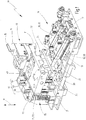
- a lifting device 10 is shown with a movable in a stroke direction H lifting part 11.
- the lifting part 11 is designed plate-shaped. It has a mounting surface 12 on which a support unit 13 - as in the embodiment shown here - and / or a clamping unit can be attached.
- the support unit 13 has a support member 14 with a support recess 15, which may be curved in cross section or prismatic. In the support recess 15, a workpiece not shown in detail in its axial extension direction can be partially encompassed and supported. In this way, axially clamped on one side in a chuck workpieces can be supported by the support unit 13 during machining at an axial distance from the chuck to avoid bending.
- a clamping unit with a tailstock or the like could be arranged on the lifting part 11.
- a free axial end of a workpiece can be clamped axially against a chuck via the clamping unit.
- the clamping unit can be mounted driveably or displaceably on the lifting part 11 transversely to the stroke direction H.
- the entire lifting device can also be displaceably mounted in a clamping direction.
- the lifting part 11 On the side opposite the mounting surface 12, the lifting part 11 has a drive side 16, which faces a base part 17.
- the base part 17 is executed in the embodiment as a base plate.
- At least one drive device 18 for moving the lifting part 11 in the stroke direction H is arranged on the base part 17.
- Each drive device 18 has a drive 19, which is formed by a double-acting fluid cylinder 20, for example.
- Each fluid cylinder 20 has two acted upon by compressed air working chambers, which are separated from each other by the piston fluidly. With the piston, a piston rod 21 is connected, which protrudes from the cylinder housing at one end.
- the free end of the piston rod 21 is coupled to a toggle mechanism 22 and, for example, acts on a knee joint 31 of the toggle mechanism 22.
- the fluid cylinder 20 can move the lifting part 11 in the stroke direction H by extending and retracting the piston rod 21 via the toggle mechanism.
- each fluid cylinder 20 has two fluid ports 23.
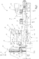
- the fluid connections are over in FIG. 3 schematically illustrated fluid lines 24 connected to a fluid control unit 25. Via the fluid control unit 25, fluid pressure is fed into one or the other working chamber of the double-acting fluid cylinder 20.
- the cylinder housing is pivotally mounted on the base part 17 at the end opposite the free end of the piston rod 21.
- hydraulic cylinders could alternatively be provided.
- drive 19 for the drive device 18 other controllable drives 19, for example, electric motors, linear motors or the like can serve as an alternative to the cylinders described here.
- a controllable drive 19 instead of a controllable drive 19 to provide a manually operated drive and to couple with the associated toggle mechanism 22. This can be, for example, an operating lever arrangement.
- a connecting piece 30 is present for this purpose, which connects the two free ends of the piston rods 21 with each other and is coupled to both knee joints 31 of the toggle mechanism.
- the toggle mechanism 22 of a drive device 18 has a first toggle lever 22a hingedly connected to the lift member 11 and a second toggle lever 22b articulated to the base member 17.
- the two toggle levers 22a, 22b of a toggle mechanism 22 are articulated to each other at the knee joint 31.
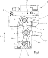
- each toggle mechanism 22 has three bearings.
- For storage of the first knee lever 22a is a at least partially accessible from the drive side 16 of the lifting member 11 first axis 32 which is secured to the lifting part 11.
- the first axis 32 is preferably used for articulated mounting of both first toggle lever 22a of the two toggle mechanism 22.
- a second axis 33 is mounted on the base part 17 and accessible at least in sections.
- the second axis 33 serves in the embodiment for the articulated mounting of the two second toggle lever 22b on the base part 17.
- the three bearing points of the toggle mechanism 22 are in FIG. 4 illustrated.
- the toggle mechanism 22 has a needle bearing 34.
- the needle bearings 34 are sealed from the environment, for example, with radial shaft seals.
- the toggle levers 22a, 22b connect their two bearings in a straight line. They have a substantially bony shape.
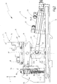
- the two drive devices 18 move the lifting part 11 between a rest position R (FIG. FIG. 3 ) and one Working position A ( FIG. 2 ).
- the lifting part 11 In the rest position R, the lifting part 11 has the smallest distance to the base part 17 and, for example, abuts the base part 17.
- the knee joint angle ⁇ formed between the two longitudinal axes of the toggle levers 22a, 22b is approximately 30 ° to 35 °.
- the longitudinal axis of the piston rod 21 forms in the rest position R, the bisector of the knee joint angle ⁇ .
- the piston rod 21 extends in the rest position R of the lifting part 11 approximately at right angles to the stroke direction H.
- the fluid cylinder 20 are pivotally mounted with its cylinder housing on the base part 17.
- the toggle levers 22a, 22b are aimed and the knee joint angle ⁇ enclosed between them becomes larger.
- the knee angle ⁇ has its maximum value and is smaller than 180 °.
- the knee joint angle ⁇ is always smaller than 180 ° in the entire range of movement of the lifting part 11 from the rest position R to the working position A.
- the knee joint angle ⁇ in the working position A is about 175 ° to 178 °.
- the working position A of the lifting part 11 is predetermined by a positioning device 40.
- the positioning device 40 determines the maximum distance between the lifting part 11 and the base part 17th
- the positioning device has a lifting part 11 and according to the example the attachment surface 12 facing stop surface 41.
- the stop surface 41 is present in the embodiment of a stop member 42.
- the stopper 42 is disposed on a pillar 43 of the positioning device 40.
- the stop member 42 is adjustably mounted on the column 43 via an adjusting device 44 in the stroke direction H.
- adjusting 44 includes a in FIG. 7 shown differential screw 45.
- This differential screw 45 connects the stop member 42 with the column 43, so that a very accurate adjustment of the distance between the stop member with the stop surface 41 and the base member 17 is possible.
- the stop member 42 is guided in guide recesses 43 on the halls.
- To lock the adjusted position of the stop member 42 may serve a clamping screw which extends transversely to the stroke direction H and the position of the stop member 42 relative to the column 43 fixed, for example, in which it prevents an adjustment or rotation of the differential screw 45.
- FIG. 6 The representation in FIG. 6 is incomplete and does not show the stopper 42.
- the differential screw 45 and the pins 46 of the adjusting device 44 are in FIG. 7 shown.
- the stop member 42 has an extension of the column 43 extending parallelepiped portion 47.
- two cross members 48 extend transversely to the stroke direction H in opposite directions away from this cuboid section 47. This results in a total T-shaped shape of the stop member 42.
- At each cross member 48 is on the base part 17 or the lifting part 11 side facing a portion 41 a of the stop surface 41 is provided.
- the stop surface 41 is thus not contiguous, but consists of two spaced-apart portions 41 a, in each case a cross member 48th
- the lifting part 11 is an in FIG. 6 illustrated recess 50 available. Through this recess 50 protrudes in the rest position R, the column 43 and in the working position A of the rectangular portion 47 of the stop member 42 therethrough. In FIG. 6 is the column 43 and the stop member 42 is not shown for clarity.
- the column 43 and the rectangular portion 47 of the positioning device 40 are not used to guide the lifting member 11 in the stroke direction H, but only pass through the recess 50.
- Between the positioning device 40 and the lifting part 11 may be present in the region of the recess 50, a gap , so that in the rest position R of the lifting part 11 and during the movement of the lifting part 11 in the stroke direction H there is no guide contact between the positioning device 40 and the lifting part 11.
- a guide device 55 which has two parallel to each other in the stroke direction H extending guide rails 56 in the embodiment. These are encompassed by a firmly connected to the lifting part 11 guide member 57.
- the abutment surface 41 of the positioning device 40 and, according to the stopper part 42, is assigned a contact surface 60 on the lifting part 11, wherein the abutment surface 60 is formed by a portion of the attachment surface 12 in the exemplary embodiment.
- the contact surface 60 is particularly good in FIGS. 5 and 6 recognizable.
- the contact surface 60 also has two spaced apart surface portions 60a, which are each associated with a portion 41a of the stop surface 41.
- the lifting member 11 is in its working position A, the abutment surface 60 is located on the stop surface 41 at.
- neither the contact surface 60, nor the stop surface 41 are designed as flat surfaces, which would also be possible in a modification of the embodiment.
- the abutment surface 60 of the lifting part 11 is arranged on a plurality of positioning projections 61.
- Each positioning projection 61 is associated with a positioning recess 62, wherein the stop surface 41 is present at this positioning recesses 62. In the working position A of the lifting part 11, each positioning projection 61 engages in the associated positioning recess 62.
- the stop surface 41 provided either on Positioniervorsprüngen 61 or on Positioniervorsprüngen 61 and positioning recesses 62, wherein the abutment surface 60 may be formed corresponding to associated positioning recesses 62 or 62 and Positioniervertiefgen positioning projections 61.
- the positioning projections 61 have seen in cross-section a prismatic and, for example, a trapezoidal shape. They taper off the lifting part 11 away.
- the associated positioning recesses 62 have a cross-section adapted to the cross-sectional shape of the positioning projections 61, which in the embodiment is triangular in shape. Due to the triangular cross section of the positioning recesses 62 and the trapezoidal cross section the positioning protrusions 61 remains in the working position A of the lifting part 11 at the bottom of each positioning recess 62 a small clearance with respect to the engaging positioning projection 61, as shown in FIG FIG. 5 can be seen.
- the stop member 42 and the lifting member 11 abut each other only on the respective inclined surfaces of the positioning projections 61 and the positioning recesses 62, which thus form the stop surface 41 and the abutment surface 60.
- This configuration of the contact surface 60 and the stop surface 41 allows a very exact positioning of the lifting part 11 relative to the positioning device 40 and, according to the example, with respect to the stop part 42.
- the prism-shaped positioning projections 61 extend at right angles to the stroke direction H. At least one of the prism-shaped positioning projections 61 extends at right angles to the other positioning projections 61. As a result, the position of the lifting member 11 in the working position A is exactly radial to the stroke direction H by the positioning device 40 specified.
- each fluid cylinder 20 of the two drive devices 18 is subjected to a fluid pressure, so that via the piston rod 21 and the two toggle mechanism 22, the lifting member 11 is pressed with its contact surface 60 against the stop surface 41 of the positioning device 40.
- the forces acting on the lifting part 11 transverse forces transverse to the stroke direction H are supported by the positioning recesses 62 in the stop member 42 and thus do not act on the guide means 55.
- Both in the stroke direction H, as well as transversely to the stroke direction H is an exact positioning of the lifting member 11 in the Working position A reached. This working position A can with be approached very high accuracy.
- the support unit 13 arranged on the lifting part 11 always very accurately assumes the predetermined target position for supporting the associated workpiece.
- the lifting part 11 and therefore also the support unit 13 can be positioned on a micrometer exactly in the stroke direction H and transversely thereto.
- the working position A is predetermined by the positioning device 40 such that the two toggle levers 22a, 22b of a toggle mechanism 22 are outside their extended position, a sufficient force can be exerted on the lifting part 11 via the associated drive 19, with which the lifting part 11 is pressed in the working position A against the stop surface 41 of the positioning device 40. Since the knee joint angle ⁇ in the working position A is large in magnitude, sufficient for holding the lifting member 11 in the working position A usual pneumatic operating pressures in the range of 5 to 6 bar, as they are usually available in factories anyway.
- the lifting speed of the lifting part 11 is further limited by the fact that in the fluid lines 24 fluid throttles 24a are used ( FIG. 3 ).
- Each drive device 18 or at least one of the drive devices 18 may have a sensor unit 65 for detecting at least the working position A and the rest position R of the lifting part 11.
- the sensor unit 65 has two limit switches 66 in the relevant fluid cylinder 20, via which detects the position of the piston rod 21 and the piston mounted in the cylinder housing and therefore indirectly the working position A and the rest position R of the lifting part 11 can be determined.
- One of the limit switches 66 delivers upon reaching the working position A, a first sensor signal S1.
- the respective other limit switch 66 of the fluid cylinder 20 delivers a second sensor signal S2.
- the knee joint angle ⁇ is relatively small, so that the force acting on the knee joint 31 of the toggle mechanism 22 by the drive 19 generates only a small force component in the stroke direction H. This can lead to a relatively large driving force being required in order to be able to move the lifting part 11 out of the rest position R.
- an auxiliary drive 70 is present in the lifting device 10 described here.
- the auxiliary drive 70 provided an auxiliary force in the stroke direction H, which acts at least in the rest position R directly or indirectly on the lifting part 11.
- the auxiliary power of the auxiliary drive 70 therefore, the lifting movement of the lifting member 11 is supported from the rest position R out in the direction of the working position A.
- the auxiliary drive 70 has a deformable body 71, which is deformed in the rest position R and compressed according to the example, whereby he provides the auxiliary power in the stroke direction H in the rest position R.
- a deformable body 71 is used in the embodiment, a compression or coil spring 72 whose longitudinal axis extends in the stroke direction H.
- the pressure or coil spring 72 is arranged parallel to the guide rails 56 in the region of the guide device 55. Your one end is supported on the base part 17. The opposite end is located on a support member 73, which is fastened according to example directly on the lifting part 11. The force exerted by the compression or coil spring 72 spring force in the stroke direction H is thus on the support member 73 on the lifting part 11 a.
- the support member 73 is applied over the entire stroke of the lifting member 11 to the compression or coil spring 72.
- the spring force or auxiliary force in the stroke direction H therefore increases or decreases over the entire stroke of the lifting part 11. As a result, force jumps are avoided by the auxiliary drive 70 in the stroke direction H.
- the deformable body 71 could also be formed by a leaf spring or an elastomeric body. It would also be possible for the deformable body 71 to be in contact with the support part 73 or another element connected to the lift part 11 only at a certain knee-joint angle range starting from the rest position R. However, it can force jumps of the auxiliary force in the stroke direction H arise.
- the invention relates to a lifting device 10 with a lifting direction H between a rest position R and a working position A linearly movable lifting part 11.
- Das Hubteil 11 carries a support unit 13 for a workpiece and / or a clamping unit for this workpiece.
- At least one drive device 18 and in particular two drive devices 18 serve to move the lifting part 11.
- Each drive device 18 has a toggle mechanism 22, which has a first toggle lever 22a mounted pivotably on the lifting part 11 and a second toggle lever 22b mounted on a base part 17.
- the two toggle levers 22a, 22b are pivotally mounted to one another at a common knee joint 31. At the knee joint 32, a drive 19 of the drive unit 18 engages.
- a positioning device 40 specifies the position of the lifting part 11 in the stroke direction H and in particular also transversely to the stroke direction H in the working position A.
- it preferably has a stop surface 41, against which the lifting part 11 is pressed via the at least one drive means 18 in the working position A.
- this working position A of the knee joint angle ⁇ of the toggle mechanism 22 is smaller than 180 °, so that the two toggle levers 22a and 22b of the toggle mechanism 22 are outside the extended position.
Description
Die Erfindung betrifft eine Hubvorrichtung mit einem in Hubrichtung zwischen einer Arbeitsstellung und einer Ruhestellung bewegbaren Hubteil. An dem Hubteil ist eine Stützeinheit und/oder eine Spanneinheit zum Abstützen bzw. zum Einspannen eines Werkstücks angeordnet. Die Stützeinheit kann beispielsweise eine Lünette zum Abstützen eines zylindrischen Werkstücks sein. Die Spanneinheit kann beispielsweise einen Reitstock oder ein ähnliches Spannmittel aufweisen, um ein Werkstück insbesondere axial zu spannen. Die Hubvorrichtung dient vorzugsweise zur Verwendung in Schleifmaschinen beim Schleifen von zylindrischen Werkstücken.The invention relates to a lifting device with a movable in the stroke direction between a working position and a rest position lifting part. On the lifting part, a support unit and / or a clamping unit for supporting or for clamping a workpiece is arranged. The support unit may for example be a bezel for supporting a cylindrical workpiece. The clamping unit may for example have a tailstock or a similar clamping means to clamp a workpiece in particular axially. The lifting device is preferably for use in grinding machines when grinding cylindrical workpieces.
Ein Hubtisch ist beispielsweise aus
Der Antrieb wird dabei zwischen dem Basisteil und der Tischplatte durch die Hebelanordnung getragen und beim Bewegen der Tischplatte in Hubrichtung mitbewegt. Dies ist deswegen ungünstig, weil die Masse des Antriebs vollständig mitbewegt werden muss. Es hat sich außerdem gezeigt, dass das Anfahren der Arbeitsstellung bei derartigen Hubtischen für viele Anwendungen zu ungenau ist. Insbesondere bei der Abstützung oder beim Einspannen von Werkstücken in Präzisionsmaschinen muss die Arbeitsstellung des Hubteils der Hubvorrichtung auf wenige Mikrometer genau eingestellt werden können.The drive is carried between the base part and the table top by the lever assembly and moved when moving the table top in the stroke direction. This is unfavorable because the mass of the drive must be completely moved. It has also been shown that the approach of the working position in such lifting tables for many applications is too inaccurate. Especially at the Support or when clamping workpieces in precision machines, the working position of the lifting part of the lifting device must be able to be set to a few micrometers accurate.
Aus
Weitere Hubvorrichtungen mit Kniehebelgetrieben sind beispielsweise aus
Es kann daher als Aufgabe der vorliegenden Erfindung angesehen werden eine Hubvorrichtung zu schaffen, die eine hohe Genauigkeit beim Anfahren der Arbeitsstellung des in einer Hubrichtung bewegten Hubteils erreicht.It can therefore be regarded as an object of the present invention to provide a lifting device, the one achieved high accuracy when approaching the working position of the moving in a stroke direction of the lifting part.
Diese Aufgabe wird durch die Hubvorrichtung mit den Merkmalen des Patentanspruches 1 gelöst.This object is achieved by the lifting device with the features of
Die Hubvorrichtung weist eine an einem Basisteil angeordnete Antriebseinrichtung auf. Zu der Antriebseinrichtung gehört ein mit einem Kniehebelgetriebe gekoppelter Antrieb. Ein erster Kniehebel des Kniehebelgetriebes ist am Hubteil und der andere Kniehebel des Kniehebelgetriebes ist am Basisteil angelenkt. Vorzugsweise beaufschlagt der Antrieb das Kniegelenk des Kniehebelgetriebes. Über eine Positioniereinrichtung wird die Arbeitsstellung des Hubteils vorgegeben. Insbesondere definiert die Positioniereinrichtung den maximalen Abstand zwischen dem Hubteil und dem Basisteil, so dass beim Bewegen des Hubteils in Hubrichtung vom Basisteil weg die Arbeitsstellung exakt angefahren werden kann. Um das Hubteil genau in der gewünschten Arbeitsstellung zu halten, ist die Positioniereinrichtung gegenüber dem Kniehebelgetriebe so justiert bzw. eingestellt, dass sich die Kniehebel außerhalb ihrer Strecklage befinden, wenn das Hubteil die Arbeitsstellung erreicht hat. Insbesondere wird die Strecklage der Kniehebel während der gesamten Bewegung zwischen der Ruhestellung und der Arbeitsstellung des Hubteils nicht erreicht. Der Kniegelenkwinkel zwischen den beiden Kniehebeln beträgt in der Ruhestellung vorzugsweise 30° bis 40° und in der Arbeitsstellung vorzugsweise 170° bis 178°.The lifting device has a drive unit arranged on a base part. To the drive means includes a coupled with a toggle gear drive. A first toggle lever of the toggle mechanism is on the lifting part and the other toggle lever of the toggle mechanism is hinged to the base part. Preferably, the drive acts on the knee joint of the toggle mechanism. About a positioning the working position of the lifting part is specified. In particular, the positioning device defines the maximum distance between the lifting part and the base part, so that when moving the lifting part in the stroke direction away from the base part, the working position can be approached exactly. In order to keep the lifting part exactly in the desired working position, the positioning device relative to the toggle mechanism is adjusted or adjusted so that the toggle are out of their extended position when the lifting part has reached the working position. In particular, the extended position of the toggle lever is not reached during the entire movement between the rest position and the working position of the lifting part. The knee joint angle between the two toggle levers is in the rest position preferably 30 ° to 40 ° and in the working position preferably 170 ° to 178 °.
Dadurch, dass die Kniehebel des Kniehebelgetriebes in der Arbeitsstellung einen Kniegelenkwinkel von kleiner als 180° einschließen, kann über den Antrieb der wenigstens einen Antriebseinrichtung über das Kniehebelgetriebe eine ausreichend große Kraft auf das Hubteil in Hubrichtung ausgeübt werden, so dass es exakt in die durch die Positioniereinrichtung definierte Position gedrückt wird. Auf diese Weise ist die Arbeitsstellung des Hubteils unabhängig von einem Spiel in der Antriebseinrichtung exakt erreicht.Because the toggle lever of the toggle mechanism in the working position include a knee joint angle of less than 180 °, a sufficiently large force can be exerted on the lifting part in the stroke direction on the drive of the at least one drive means via the toggle mechanism so that it is pressed exactly into the position defined by the positioning device. In this way, the working position of the lifting part is achieved independently of a game in the drive device exactly.
Vorzugsweise besteht das Kniehebelgetriebe der wenigstens einen Antriebseinrichtung aus nur zwei Kniehebeln, wobei jeder Kniehebel insbesondere geradlinig zwischen zwei Lagerstellen verläuft. Das Kniehebelgetriebe weist daher neben dem Kniegelenk bevorzugt nur zwei weitere Lagerstellen auf.The toggle mechanism of the at least one drive device preferably consists of only two toggle levers, wherein each toggle lever in particular runs in a straight line between two bearing points. The toggle mechanism therefore preferably has only two additional bearings in addition to the knee joint.
Die Positioniereinrichtung hat eine dem Hubteil zugewandte Anschlagfläche, die in der Arbeitsstellung an einer Anlagefläche des Hubteils anliegt. Die Positioniereinrichtung hat eine Säule, die sich ausgehend vom Basisteil durch eine Aussparung im Hubteil erstreckt und an ihrem dem Basisteil abgewandten Ende ein Anschlagteil mit der Anschlagfläche trägt. Vorzugsweise gelangen die Anschlagfläche und die Anlagefläche nur in der Arbeitsstellung miteinander in Kontakt. Außerhalb der Arbeitsstellung beeinflusst die Positioniereinrichtung die Lage des Hubteils vorzugsweise nicht. Die Positioniereinrichtung und das Hubteil sind insbesondere aus Stahl hergestellt. Die Arbeitsstellung lässt sich dabei besonders genau definieren.The positioning device has a lifting surface facing the stop surface, which rests in the working position on a contact surface of the lifting part. The positioning device has a column, which extends from the base part through a recess in the lifting part and carries at its end facing away from the base part a stop member with the stop surface. Preferably, the stop surface and the contact surface come into contact only in the working position. Outside the working position, the positioning device preferably does not influence the position of the lifting part. The positioning and the lifting part are made in particular of steel. The working position can be defined very precisely.
Es ist von Vorteil, wenn die Positioniereinrichtung eine Einstelleinrichtung zur Einstellung des Abstandes zwischen dem Basisteil und der Anschlagfläche aufweist. Auf diese Weise kann die Arbeitsstellung des Hubteils eingestellt und an die Anforderungen der Werkzeugmaschine angepasst werden. Zur exakten Einstellung kann die Einstelleinrichtung eine Differenzialschraube aufweisen. Über diese Differenzialschraube kann beispielsweise ein Anschlagteil der Positioniereinrichtung, an dem die Anschlagfläche vorhanden ist, relativ zu einer mit dem Basisteil verbundenen Säule der Positioniereinrichtung in Hubrichtung in der gewünschten Position eingestellt werden.It is advantageous if the positioning device has an adjusting device for adjusting the distance between the base part and the stop surface. In this way, the working position of the lifting part can be adjusted and adapted to the requirements of the machine tool. For exact adjustment, the adjustment can have a differential screw. About this differential screw, for example, a stop member of the positioning, on which the stop surface is present is to be adjusted in the desired position relative to a column of the positioning device connected to the base part in the stroke direction.
Zur Fixierung der Position der Anschlagfläche kann eine quer zur Differenzialschraube angeordnete Spannschraube dienen, die die Differenzialschraube beaufschlagt und gegen eine versehentliche Drehung sichert.For fixing the position of the abutment surface, a clamping screw arranged transversely to the differential screw can serve, which acts on the differential screw and secures it against an accidental rotation.
Bei einer bevorzugten Ausführungsform ist an der Anschlagfläche und/oder an der Anlagefläche wenigstens ein Positioniervorsprung vorhanden, der mit einer zugeordneten Positioniervertiefung an der jeweils anderen Fläche zusammenarbeitet. Der Positioniervorsprung und/oder die Positioniervertiefung kann im Querschnitt gesehen prismenförmig sein, beispielsweise dreieckförmig oder trapezförmig. Dabei kann die Anlagefläche und die Anschlagfläche ausschließlich durch die jeweiligen Schrägflächen des wenigstens einen Positioniervorsprungs bzw. der jeweils zugeordneten Positioniervertiefung gebildet sein.In a preferred embodiment, at least one positioning projection is provided on the abutment surface and / or on the abutment surface, which cooperates with an associated positioning indentation on the respective other surface. The positioning projection and / or the positioning recess may be prismatic in cross-section, for example triangular or trapezoidal. In this case, the contact surface and the abutment surface can be formed exclusively by the respective oblique surfaces of the at least one positioning projection or the respectively associated positioning recess.
Insbesondere greift der wenigstens eine Positioniervorsprung in die jeweils zugeordnete Positioniervertiefung ein, wenn sich das Hubteil in seiner Arbeitsstellung befindet. Dadurch kann das Hubteil quer oder radial zur Hubrichtung gesehen in einer exakten definierten Position gegenüber der Positioniereinrichtung positioniert werden. Über die Antriebseinrichtung quer zur Hubrichtung in das Hubteil eingeleitete Kräfte können dadurch von der Positionierreinrichtung abgestützt werden. Eine zum verschiebbaren Führen des Hubteils in Hubrichtung gegebenenfalls vorhandene Führungseinrichtung bleibt daher querkraftfrei, wenn die Antriebseinrichtung das Hubteil in die Arbeitsstellung drückt.In particular, the at least one positioning projection engages in the respectively associated positioning recess when the lifting part is in its working position. As a result, the lifting part can be positioned transversely or radially to the lifting direction in an exact defined position relative to the positioning device. By the drive means transverse to the stroke direction in the lifting part introduced forces can be supported by the positioning. A guide device for optionally displaceable guiding of the lifting part in the lifting direction therefore remains free of lateral force when the drive device presses the lifting part into the working position.
Über den wenigstens einen Positioniervorsprung und die wenigstens eine zugeordnete Positioniervertiefung kann eine spielfreie mikrometergenaue Positionierung des Hubteils in der Arbeitsstellung erfolgen. Insbesondere liegen in der Arbeitsstellung des Hubteils ausschließlich die Schrägflächen des wenigstens einen Positioniervorsprungs der Anschlagfläche und/oder der Anlagefläche an den zugeordneten Schrägflächen der wenigstens einen Positioniervertiefung der jeweils anderen Fläche an. Die Arbeitsstellung des Hubteils lässt sich wiederholbar auf einen Mikrometer genau anfahren.By means of the at least one positioning projection and the at least one associated positioning recess, play-free micrometer-accurate positioning of the lifting part in the working position can take place. In particular, in the working position of the lifting part, only the inclined surfaces of the at least one positioning projection of the stop surface and / or the contact surface abut against the associated inclined surfaces of the at least one positioning recess of the respective other surface. The working position of the lifting unit can be repeatedly approached to a micrometer.
Bei einer Ausführungsform können mehrere Antriebseinrichtungen, beispielsweise zwei Antriebseinrichtungen vorhanden sein. Jede der Antriebseinrichtungen weist einen Antrieb und ein Kniehebelgetriebe auf, wobei die Antriebseinrichtungen prinzipiell gleich aufgebaut sind. Die Kniehebelgetriebe der beiden Antriebseinrichtungen können beispielsweise auf zwei entgegengesetzten Seiten der Positioniereinrichtung bzw. der Säule der Positioniereinrichtung angeordnet sein. Dadurch kann eine gute Kraftverteilung bzw. Krafteinleitung erreicht werden. Die Antriebe der mehreren Antriebseinrichtungen können parallel geschaltet sein, so dass die Summe der Antriebskräfte aller Antriebe über alle Kniehebelgetriebe weitergeleitet wird.In one embodiment, a plurality of drive means, for example, two drive means may be present. Each of the drive devices has a drive and a toggle mechanism, wherein the drive means are basically the same structure. The toggle mechanisms of the two drive devices can be arranged, for example, on two opposite sides of the positioning device or the column of the positioning device. As a result, a good force distribution or force introduction can be achieved. The drives of the plurality of drive devices can be connected in parallel, so that the sum of the drive forces of all drives is transmitted via all toggle mechanism.
Die Antriebseinrichtung kann entweder einen ansteuerbaren Antrieb oder auch einen manuell bedienbaren Antrieb aufweisen. Der ansteuerbare Antrieb hat den Vorteil, dass das Hubteil während des Betriebs der Werkzeugmaschine bzw. während der Bearbeitung eines Werkstücks automatisiert zwischen der Ruhestellung und der Arbeitsstellung bewegt werden kann. Bei einem bevorzugten Ausführungsbeispiel kann der ansteuerbare Antrieb von einem doppelt wirkenden Fluidzylinder gebildet sein. Vorzugsweise wird ein Pneumatikzylinder verwendet. Die Kolbenstange des Fluidzylinders kann am Kniegelenk des Kniehebelgetriebes angreifen. Das Zylindergehäuse des Fluidzylinders kann dabei schwenkbar am Basisteil gelagert sein. Die Verwendung von Luft zur Betätigung des Fluidzylinders ist unproblematisch, da die Luft zwar kompressibel ist, jedoch die Arbeitsstellung des Hubteils durch die Positioniereinrichtung exakt definiert eingehalten werden kann, wenn der Pneumatikzylinder das Hubteil über das Kniehebelgetriebe in die Arbeitsstellung drückt. Wegen des relativ großen Kniegelenkwinkels von über 170° und vorzugsweise über 175° ist die Kraft, mit der das Hubteil in die Arbeitsstellung und insbesondere gegen die Anschlagfläche gedrückt wird ausreichend groß.The drive device may have either a controllable drive or a manually operated drive. The controllable drive has the advantage that the lifting part can be moved automatically between the rest position and the working position during operation of the machine tool or during machining of a workpiece. In a preferred embodiment, the controllable drive can be formed by a double-acting fluid cylinder. Preferably, a pneumatic cylinder used. The piston rod of the fluid cylinder can act on the knee joint of the toggle mechanism. The cylinder housing of the fluid cylinder can be mounted pivotably on the base part. The use of air to actuate the fluid cylinder is not a problem, since the air is indeed compressible, but the working position of the lifting part can be maintained exactly defined by the positioning when the pneumatic cylinder pushes the lifting part on the toggle mechanism in the working position. Because of the relatively large knee joint angle of over 170 ° and preferably over 175 °, the force with which the lifting part is pressed into the working position and in particular against the stop surface is sufficiently large.
Beim Bewegen des Hubteils aus der Ruhestellung in die Arbeitsstellung nimmt die Geschwindigkeit des Hubteils ab, wenn die Kolbenstange des Fluidzylinders gleichförmig bewegt wird. Dies hat den Vorteil, dass die Arbeitsstellung mit einer sich reduzierenden Hubgeschwindigkeit erreicht und ein sanfterer Stopp des Hubteils in der Arbeitsstellung durch die Positioniereinrichtung erreicht ist. Zusätzlich können in den mit dem Fluidzylinder verbundenen Fluidleitungen eine oder mehrere Drosseln angeordnet sein, um die Bewegungsgeschwindigkeit der Kolbenstange zu begrenzen. Die Steuerung der Bewegung der Kolbenstange erfolgt über den Druck an einer Fluidsteuereinheit, die beispielsweise Bestandteil der Maschinensteuerung ist.When moving the lifting part from the rest position to the working position, the speed of the lifting part decreases when the piston rod of the fluid cylinder is moved uniformly. This has the advantage that the working position is achieved with a reducing lifting speed and a gentler stop of the lifting part in the working position is achieved by the positioning. In addition, one or more throttles may be disposed in the fluid lines connected to the fluid cylinder to limit the speed of movement of the piston rod. The control of the movement of the piston rod via the pressure to a fluid control unit, which is for example part of the machine control.
Die wenigstens eine Antriebseinrichtung kann außerdem eine Fluidsteuereinheit aufweisen, die dazu eingereichtet ist, den Fluidzylinder bzw. die betreffende Arbeitskammer eines Fluidzylinders auch dann mit einem Fluiddruck zu beaufschlagen, wenn sich das Hubteil in der Arbeitstellung oder in der Ruhestellung befindet. Dadurch ist sichergestellt, dass das Hubteil mit einer ausreichend großen Kraft in der Arbeitsstellung bzw. der Ruhestellung gehalten und eine genaue Positionierung erreicht ist.The at least one drive means may further comprise a fluid control unit adapted to apply a fluid pressure to the fluid cylinder or the respective working chamber of a fluid cylinder even when the lift member is in the operative position or in the rest position. This ensures that the lifting part with a sufficiently large force held in the working position or the rest position and accurate positioning is achieved.
Die Fluidsteuereinheit kann, wenn mehrere Antriebseinrichtungen vorgesehen sind, als gemeinsame Fluidsteuereinheit für alle Antriebseinrichtungen ausgeführt sein.If a plurality of drive devices are provided, the fluid control unit can be embodied as a common fluid control unit for all drive devices.
Es ist außerdem vorteilhaft, wenn die wenigstens eine Antriebseinrichtung eine Sensoreinheit zur Erfassung der Arbeitsstellung und/oder der Ruhestellung aufweist. Beispielsweise kann der doppelt wirkende Fluidzylinder Endlagenschalter aufweisen.It is also advantageous if the at least one drive device has a sensor unit for detecting the working position and / or the rest position. For example, the double-acting fluid cylinder may have limit switches.
Es ist ferner von Vorteil, wenn ein Hilfsantrieb zusätzlich zu der wenigstens einen Antriebseinrichtung vorhanden ist. Der Hilfsantrieb weist insbesondere einen deformierbaren Körper auf, der beispielsweise von einer Schraubenfeder, einer Blattfeder, einem Elastomerkörper oder dergleichen gebildet sein kann. In der Ruhestellung des Hubteils ist der deformierbare Körper, beispielsweise die Feder, deformiert und vorzugsweise zusammengedrückt und übt daher eine Hilfskraft auf das Hubteil oder ein mit dem Hubteil verbundenes Element aus. Die Hilfskraft beaufschlagt bzw. drückt das Hubteil aus der Ruhelage heraus in Hubrichtung. Über diese Hilfskraft des Hilfsantriebs wird das Bewegen des Hubteils aus der Ruhelage heraus unterstütz. Aufgrund des kleinen Kniegelenkwinkels in der Ruhestellung ist die von der wenigstens einen Antriebseinrichtung in Hubrichtung bewirkte Hubkraft klein, so dass durch den Antrieb der Antriebseinrichtung eine erhebliche Gesamtkraft erzeugt werden müsste, um eine ausreichende Hubkraft zu erreichen. Dies kann jedoch zu unerwünscht großen Beanspruchungen führen. Derart große Gesamtkräfte des Antriebs können durch das Vorsehen des Hilfsantriebs verringert werden.It is also advantageous if an auxiliary drive is provided in addition to the at least one drive device. The auxiliary drive in particular has a deformable body, which may be formed, for example, by a helical spring, a leaf spring, an elastomer body or the like. In the rest position of the lifting part, the deformable body, for example the spring, is deformed and preferably compressed and therefore exerts an auxiliary force on the lifting part or an element connected to the lifting part. The auxiliary force acts or presses the lifting part out of the rest position in the lifting direction. About this auxiliary power of the auxiliary drive, the movement of the lifting part is supported from the rest position out. Due to the small knee joint angle in the rest position, the lifting force caused by the at least one drive device in the stroke direction is small, so that a considerable total force would have to be generated by the drive of the drive device in order to achieve a sufficient lifting force. However, this can lead to undesirably large stresses. Such large total forces of the drive can be reduced by the provision of the auxiliary drive.
Bevorzugt wird die Hilfskraft nicht nur in der Ruhestellung, sondern in jeder Position des Hubteils bereitgestellt. Die Hilfskraft kann in der Ruhestellung den größten Betrag aufweisen und mit zunehmender Entfernung bzw. Bewegung des Hubteils zur Arbeitsstellung hin abnehmen.Preferably, the auxiliary power is provided not only in the rest position, but in any position of the lifting part. The auxiliary power may have the largest amount in the rest position and decrease with increasing distance or movement of the lifting part to the working position.
Bei einer bevorzugten Ausführungsform der Hubvorrichtung ist das Hubteil über eine Führungseinrichtung in Hubrichtung linear geführt. Beispielsweise kann die Führungseinrichtung eine oder mehrere geradlinig in Hubrichtung verlaufende Führungsschienen aufweisen. Die Führungsschienen sind vorzugsweise auf der der Antriebseinrichtung entgegengesetzten Seite des Hubteils angeordnet.In a preferred embodiment of the lifting device, the lifting part is guided linearly via a guide device in the stroke direction. For example, the guide device may have one or more linear guide rails running in the stroke direction. The guide rails are preferably arranged on the drive device opposite side of the lifting part.
Vorteilhafte Ausgestaltungen der Erfindung ergeben sich aus den abhängigen Patentansprüchen und der Beschreibung. Die Beschreibung beschränkt sich auf wesentliche Merkmale der Erfindung. Die Zeichnung ist ergänzend heranzuziehen. Nachfolgend werden Ausführungsbeispiele der Hubvorrichtung anhand der beigefügten Zeichnung näher erläutert. Es zeigen:
-
Figur 1 -
Figur 2Figur 1 in einer Seitenansicht, -
Figur 3 das Ausführungsbeispiel der Hubvorrichtung gemäß derFiguren 12 in einer Seitenansicht, wobei sich das Hubteil in seiner Ruhestellung befindet, -
Figur 4 eine Detaildarstellung der Lagerstellen des Kniehebelgetriebes einer Antriebseinrichtung der Hubvorrichtung gemäß derFiguren 1 bis 3 -
Figur 5 eine Detaildarstellung eines Anschlagteils eines Ausführungsbeispiels einer Positioniereinrichtung der Hubvorrichtung gemäß derFiguren 1 bis 3 -
Figur 6 eine perspektivische Ansicht auf eine einer Anschlagfläche der Positioniereinrichtung zugeordnete Anlagefläche am Hubteil und -
Figur 7 eine Schnittdarstellung durch ein Ausführungsbeispiel einer Positioniereinrichtung mit einer Einstelleinrichtung.
-
FIG. 1 An embodiment of a lifting device in a perspective view, wherein the lifting part is in its working position, -
FIG. 2 the embodiment of the lifting deviceFIG. 1 in a side view, -
FIG. 3 the embodiment of the lifting device according to theFIGS. 1 and2 in a side view, wherein the lifting part is in its rest position, -
FIG. 4 a detailed representation of the bearings of the toggle mechanism of a drive device of the lifting device according to theFIGS. 1 to 3 . -
FIG. 5 a detailed view of a stop member of an embodiment of a positioning of the lifting device according to theFIGS. 1 to 3 . -
FIG. 6 a perspective view of a stop surface of the positioning associated with abutment surface on the lifting part and -
FIG. 7 a sectional view through an embodiment of a positioning with an adjustment.
In den
In Abwandlung zum dargestellten Ausführungsbeispiel könnte auch eine Spanneinheit mit einem Reitstock oder ähnlichem an dem Hubteil 11 angeordnet sein. Über die Spanneinheit kann beispielsweise ein freies axiales Ende eines Werkstücks axial gegen ein Spannfutter eingespannt sein. Die Spanneinheit kann hierfür quer zur Hubrichtung H antreibbar bzw. verschiebbar auf dem Hubteil 11 gelagert sein. Alternativ oder zusätzlich kann auch die gesamte Hubvorrichtung in einer Spannrichtung verschiebbar gelagert sein.In a modification to the illustrated embodiment, a clamping unit with a tailstock or the like could be arranged on the lifting
Auf der der Anbringungsfläche 12 entgegengesetzten Seite weist das Hubteil 11 eine Antriebsseite 16 auf, die einem Basisteil 17 zugewandt ist. Das Basisteil 17 ist beim Ausführungsbeispiel als Basisplatte ausgeführt. An dem Basisteil 17 ist wenigstens eine Antriebseinrichtung 18 zum Bewegen des Hubteils 11 in Hubrichtung H angeordnet. Bei dem hier beschriebenen Ausführungsbeispiel sind zwei gleichartig aufgebaute Antriebseinrichtungen 18 vorhanden. Jede Antriebseinrichtung 18 weist einen Antrieb 19 auf, der beispielsgemäß von einem doppelt wirkenden Fluidzylinder 20 gebildet ist. Jeder Fluidzylinder 20 weist zwei mit Druckluft beaufschlagbare Arbeitskammern auf, die durch den Kolben voneinander fluidisch getrennt sind. Mit dem Kolben ist eine Kolbenstange 21 verbunden, die an einem Ende aus dem Zylindergehäuse herausragt. Das freie Ende der Kolbenstange 21 ist mit einem Kniehebelgetriebe 22 gekoppelt und greift beispielsgemäß an einem Kniegelenk 31 des Kniehebelgetriebes 22 an. Auf diese Weise kann der Fluidzylinder 20 durch Ausfahren und Einfahren der Kolbenstange 21 über das Kniehebelgetriebe das Hubteil 11 in Hubrichtung H bewegen.On the side opposite the mounting
Zur Beaufschlagung der Arbeitskammern weist jeder Fluidzylinder 20 zwei Fluidanschlüsse 23 auf. Die Fluidanschlüsse sind über in
Anstelle der pneumatischen Fluidzylinder 20 könnten alternativ auch Hydraulikzylinder vorgesehen sein. Als Antrieb 19 für die Antriebseinrichtung 18 können alternativ zu den hier beschriebenen Zylindern auch andere ansteuerbare Antriebe 19, beispielsweise Elektromotoren, Linearmotoren oder dergleichen dienen. Es ist ferner auch möglich, anstelle eines ansteuerbaren Antriebs 19 einen manuell betätigten Antrieb vorzusehen und mit dem zugeordneten Kniehebelgetriebe 22 zu koppeln. Dies kann beispielsweise eine Bedienhebelanordnung sein.Instead of the pneumatic fluid cylinder 20, hydraulic cylinders could alternatively be provided. As drive 19 for the
Wie insbesondere in
Das Kniehebelgetriebe 22 einer Antriebseinrichtung 18 weist einen gelenkig mit dem Hubteil 11 verbundenen ersten Kniehebel 22a sowie einen gelenkig am Basisteil 17 gelagerten zweiten Kniehebel 22b auf. Die beiden Kniehebel 22a, 22b eines Kniehebelgetriebes 22 sind an dem Kniegelenk 31 gelenkig aneinander gelagert. Somit weist jedes Kniehebelgetriebe 22 drei Lagerstellen auf. Zur Lagerung des ersten Kniehebels 22a dient eine von der Antriebsseite 16 des Hubteils 11 zumindest abschnittweise zugängliche erste Achse 32, die am Hubteil 11 befestigt ist. Die erste Achse 32 dient vorzugsweise zur gelenkigen Lagerung beider ersten Kniehebel 22a der beiden Kniehebelgetriebe 22. In Hubrichtung H unterhalb der ersten Achse 32 ist am Basisteil 17 eine zweite Achse 33 gelagert und zumindest abschnittweise zugänglich. Die zweite Achse 33 dient beim Ausführungsbeispiel zur gelenkigen Lagerung der beiden zweiten Kniehebel 22b am Basisteil 17. Die drei Lagerstellen des Kniehebelgetriebes 22 sind in
Die Kniehebel 22a, 22b verbinden ihre beiden Lagerstellen jeweils geradlinig. Sie haben eine im Wesentlichen knochenförmige Gestalt.The toggle levers 22a, 22b connect their two bearings in a straight line. They have a substantially bony shape.
Die beiden Antriebseinrichtungen 18 bewegen das Hubteil 11 zwischen einer Ruhestellung R (
Da sich der Abstand des Kniegelenks 31 gegenüber dem Basisteil 17 bei der Bewegung des Hubteils 11 aus der Ruhestellung R in die Arbeitsstellung A vergrößert, sind die Fluidzylinder 20 mit ihrem Zylindergehäuse schwenkbar am Basisteil 17 gelagert. Durch das Ausfahren der Kolbenstange 21 richten sich die Kniehebel 22a, 22b auf und der dazwischen eingeschlossene Kniegelenkwinkel α wird größer. In der Arbeitsstellung A hat der Kniegelenkwinkel α seinen Maximalwert und ist kleiner als 180°. Die Kniehebel 22a, 22b nehmen also auch in der Arbeitsstellung A nicht ihre Strecklage (Kniegelenkwinkel α = 180°) ein. Der Kniegelenkwinkel α ist im gesamten Bewegungsbereich des Hubteils 11 von der Ruhestellung R in die Arbeitsstellung A stets kleiner als 180°. Beim Ausführungsbeispiel beträgt der Kniegelenkwinkel α in der Arbeitsstellung A etwa 175° bis 178°.Since the distance of the knee joint 31 relative to the
Die Arbeitsstellung A des Hubteils 11 wird durch eine Positioniereinrichtung 40 vorgegeben. Die Positioniereinrichtung 40 bestimmt dabei den maximalen Abstand zwischen dem Hubteil 11 und dem Basisteil 17.The working position A of the lifting
Bei dem hier beschriebenen Ausführungsbeispiel weist die Positioniereinrichtung eine dem Hubteil 11 und beispielsgemäß der Anbringungsfläche 12 zugewandte Anschlagfläche 41 auf. Die Anschlagfläche 41 ist beim Ausführungsbeispiel an einem Anschlagteil 42 vorhanden. Das Anschlagteil 42 ist an einer Säule 43 der Positioniereinrichtung 40 angeordnet.In the embodiment described here, the positioning device has a lifting
Das Anschlagteil 42 ist über eine Einstelleinrichtung 44 in Hubrichtung H verstellbar an der Säule 43 gelagert. Zur Einstelleinrichtung 44 gehört eine in
Die Darstellung in
Das Anschlagteil 42 weist einen sich in Verlängerung der Säule 43 erstreckenden quaderförmigen Abschnitt 47 auf. An dem der Säule 43 abgewandten Ende erstrecken sich von diesem quaderförmigen Abschnitt 47 zwei Querteile 48 quer zur Hubrichtung H in entgegengesetzte Richtungen weg. Dadurch entsteht eine insgesamt T-förmige Gestalt des Anschlagteils 42. An jedem Querteil 48 ist auf der dem Basisteil 17 bzw. dem Hubteil 11 zugewandten Seite ein Abschnitt 41a der Anschlagfläche 41 vorgesehen. Die Anschlagfläche 41 ist somit nicht zusammenhängend, sondern besteht aus zwei voneinander beabstandeten Abschnitten 41a an jeweils einem Querteil 48.The
In dem Hubteil 11 ist eine in
Zur Führung des Hubteils 11 in Hubrichtung H dient eine Führungseinrichtung 55, die beim Ausführungsbeispiel zwei sich parallel zueinander in Hubrichtung H erstreckende Führungsschienen 56 aufweist. Diese werden von einem mit dem Hubteil 11 fest verbundenen Führungsteil 57 umgriffen.To guide the lifting
Der Anschlagfläche 41 der Positioniereinrichtung 40 und beispielsgemäß des Anschlagteils 42 ist eine Anlagefläche 60 am Hubteil 11 zugeordnet, wobei die Anlagefläche 60 beim Ausführungsbeispiel durch einen Abschnitt der Anbringungsfläche 12 gebildet ist. Die Anlagefläche 60 ist besonders gut in
Bei dem hier veranschaulichten bevorzugten Ausführungsbeispiel sind weder die Anlagefläche 60, noch die Anschlagfläche 41 als ebene Flächen ausgeführt, was in Abwandlung zum Ausführungsbeispiel auch möglich wäre. Beispielsgemäß ist die Anlagefläche 60 des Hubteils 11 an mehrere Positioniervorsprüngen 61 angeordnet. Jedem Positioniervorsprung 61 ist eine Positioniervertiefung 62 zugeordnet, wobei die Anschlagfläche 41 an diesen Positioniervertiefungen 62 vorhanden ist. In der Arbeitsstellung A des Hubteils 11 greift jeder Positioniervorsprung 61 in die zugeordnete Positioniervertiefung 62 ein.In the preferred embodiment illustrated here, neither the
Es wäre in Abwandlung zu der dargestellten Ausführung auch möglich die Anschlagfläche 41 entweder an Positioniervorsprüngen 61 oder an Positioniervorsprüngen 61 und Positioniervertiefungen 62 vorzusehen, wobei die Anlagefläche 60 entsprechend an zugeordneten Positioniervertiefungen 62 oder an Positioniervertiefungen 62 und Positioniervorsprüngen 61 ausgebildet sein kann.It would also be possible in a modification of the illustrated embodiment, the
Bei dem hier dargestellten Ausführungsbeispiel haben die Positioniervorsprünge 61 im Querschnitt gesehen eine prismenförmige und beispielsweise eine trapezförmige Gestalt. Sie verjüngen sich vom Hubteil 11 weg. Die zugeordneten Positioniervertiefungen 62 haben einen an die Querschnittsform der Positioniervorsprünge 61 angepassten Querschnitt, der beim Ausführungsbeispiel dreieckförmig gestaltet ist. Aufgrund des dreieckförmigen Querschnitts der Positioniervertiefungen 62 und des trapezförmigen Querschnitts der Positioniervorsprünge 61 verbleibt in der Arbeitsstellung A des Hubteils 11 am Grund jeder Positioniervertiefung 62 ein kleiner Freiraum gegenüber dem eingreifenden Positioniervorsprung 61, wie dies in
Durch diese Ausgestaltung der Anlagefläche 60 und der Anschlagfläche 41 lässt sich eine sehr exakte Positionierung des Hubteils 11 gegenüber der Positioniereinrichtung 40 und beispielsgemäß gegenüber dem Anschlagteil 42 erreichen. Die prismenförmigen Positioniervorsprünge 61 erstrecken sich beim Ausführungsbeispiel rechtwinklig zur Hubrichtung H. Wenigstens einer der prismenförmigen Positioniervorsprünge 61 erstreckt sich beim Ausführungsbeispiel rechtwinklig zu den anderen Positioniervorsprüngen 61. Dadurch ist die Lage des Hubteils 11 in der Arbeitsstellung A radial zur Hubrichtung H durch die Positioniereinrichtung 40 genau vorgegeben.This configuration of the
Über die Fluidsteuereinheit 25 wird jeder Fluidzylinder 20 der beiden Antriebseinrichtungen 18 mit einem Fluiddruck beaufschlagt, so dass über die Kolbenstange 21 und die beiden Kniehebelgetriebe 22 das Hubteil 11 mit seiner Anlagefläche 60 gegen die Anschlagfläche 41 der Positioniereinrichtung 40 gedrückt wird. Die dabei auf das Hubteil 11 einwirkenden Querkräfte quer zur Hubrichtung H werden durch die Positioniervertiefungen 62 im Anschlagteil 42 abgestützt und wirken somit nicht auf die Führungseinrichtung 55. Sowohl in Hubrichtung H, als auch quer zur Hubrichtung H ist eine exakte Positionierung des Hubteils 11 in der Arbeitsstellung A erreicht. Diese Arbeitsstellung A kann mit sehr hoher Genauigkeit angefahren werden. Dadurch ist sichergestellt, dass beim automatischen Bewegen des Hubteils 11 zwischen seiner Ruhestellung R und seiner Arbeitsstellung A die auf dem Hubteil 11 angeordnete Stützeinheit 13 immer wieder sehr exakt die vorgegebene Sollposition zur Abstützung des zugeordneten Werkstücks einnimmt. Bei dem hier beschriebenen Ausführungsbeispiel kann das Hubteil 11 und mithin auch die Stützeinheit 13 bis auf einem Mirkometer genau in Hubrichtung H und quer dazu positioniert werden.Via the
Dadurch, dass durch die Positioniereinrichtung 40 die Arbeitsstellung A derart vorgegeben ist, dass sich die beiden Kniehebel 22a, 22b eines Kniehebelgetriebes 22 außerhalb ihrer Strecklage befinden, kann über den zugeordneten Antrieb 19 eine ausreichende Kraft auf das Hubteil 11 ausgeübt werden, mit der das Hubteil 11 in der Arbeitsstellung A gegen die Anschlagfläche 41 der Positioniereinrichtung 40 gedrückt wird. Da der Kniegelenkwinkel α in der Arbeitsstellung A betragsmäßig groß ist, genügen zum Halten des Hubteils 11 in der Arbeitsstellung A übliche pneumatische Betriebsdrücke im Bereich von 5 bis 6 bar, wie sie in Fabrikhallen üblicherweise ohnehin zur Verfügung stehen.Due to the fact that the working position A is predetermined by the
Beim Bewegen des Hubteils 11 aus der Ruhestellung R in die Arbeitsstellung A nimmt beim gleichförmigen Ausfahren des Kolbenstange 21 die Geschwindigkeit des Hubteils 11 in Hubrichtung H mit zunehmendem Kniegelenkwinkel α ab. Dies ist deswegen vorteilhaft, da das Hubteil 11 trotz gleichförmig bewegter Kolbenstange 21 mit geringer Geschwindigkeit an der Anschlagfläche 41 der Positioniereinrichtung 40 anschlägt. Bei dem hier beschriebenen Ausführungsbeispiel wird die Hubgeschwindigkeit des Hubteils 11 weiter dadurch begrenzt, dass in den Fluidleitungen 24 Fluiddrosseln 24a eingesetzt sind (
Jede Antriebseinrichtung 18 oder zumindest eine der Antriebseinrichtungen 18 kann eine Sensoreinheit 65 zur Erfassung zumindest der Arbeitsstellung A und der Ruhestellung R des Hubteils 11 aufweisen. Bei dem hier beschriebenen Ausführungsbeispiel weist die Sensoreinheit 65 zwei Endlagenschalter 66 im betreffenden Fluidzylinder 20 auf, über den die Position der Kolbenstange 21 bzw. des im Zylindergehäuse gelagerten Kolbens erfasst und daher mittelbar die Arbeitsstellung A und die Ruhestellung R des Hubteils 11 festgestellt werden kann. Einer der Endlagenschalter 66 liefert bei Erreichen der Arbeitsstellung A ein erstes Sensorsignal S1. Bei Erreichen der Ruhestellung R liefert der jeweils andere Endlagenschalter 66 des Fluidzylinders 20 ein zweites Sensorsignal S2.Each
In der Ruhestellung R ist der Kniegelenkwinkel α relativ klein, so dass die von dem Antrieb 19 auf das Kniegelenk 31 des Kniehebelgetriebes 22 einwirkende Kraft nur eine geringe Kraftkomponente in Hubrichtung H erzeugt. Dies kann dazu führen, dass eine relativ große Antriebskraft erforderlich ist, um das Hubteil 11 aus der Ruhestellung R bewegen zu können. Um die Forderung nach relativ großen Antriebskräften über die Antriebseinheit 18 in der Ruhestellung R des Hubteils 11 zu vermeiden, ist bei der hier beschriebenen Hubvorrichtung 10 ein Hilfsantrieb 70 vorhanden. Der Hilfsantrieb 70 stellte eine Hilfskraft in Hubrichtung H zur Verfügung, die zumindest in der Ruhestellung R mittelbar oder unmittelbar auf das Hubteil 11 einwirkt. Über die Hilfskraft des Hilfsantriebs 70 wird daher die Hubbewegung des Hubteils 11 aus der Ruhestellung R heraus in Richtung der Arbeitsstellung A unterstützt.In the rest position R, the knee joint angle α is relatively small, so that the force acting on the
Der Hilfsantrieb 70 weist einen deformierbaren Körper 71 auf, der in der Ruhestellung R deformiert und beispielsgemäß zusammengedrückt ist, wodurch er in der Ruhestellung R die Hilfskraft in Hubrichtung H bereitstellt. Als deformierbarer Körper 71 dient beim Ausführungsbeispiel eine Druck- oder Schraubenfeder 72, deren Längsachse sich in Hubrichtung H erstreckt. Die Druck- oder Schraubenfeder 72 ist im Bereich der Führungseinrichtung 55 parallel zu den Führungsschienen 56 angeordnet. Ihr eines Ende stützt sich am Basisteil 17 ab. Das entgegengesetzte Ende liegt an einem Stützteil 73 an, das beispielsgemäß unmittelbar am Hubteil 11 befestigt ist. Die von der Druck- oder Schraubenfeder 72 ausgeübte Federkraft in Hubrichtung H wird somit über das Stützteil 73 auf das Hubteil 11 ein.The
Bei dem hier beschriebenen Ausführungsbeispiel liegt das Stützteil 73 über den gesamten Hubweg des Hubteils 11 an der Druck- oder Schraubenfeder 72 an. Die Federkraft bzw. Hilfskraft in Hubrichtung H nimmt daher über den gesamten Hubweg des Hubteils 11 zu bzw. ab. Dadurch werden Kraftsprünge durch den Hilfsantrieb 70 in Hubrichtung H vermieden.In the embodiment described here, the
Alternativ zu den hier beschriebenen Ausführungsbeispiel könnte der deformierbare Körper 71 auch von einer Blattfeder oder einem Elastomerkörper gebildet sein. Es wäre auch möglich, dass der deformierbare Körper 71 lediglich in einem bestimmten Kniegelenkwinkelbereich ausgehend von der Ruhestellung R in Kontakt mit dem Stützteil 73 oder einem anderen mit dem Hubteil 11 verbundenen Element steht. Allerdings können dabei Kraftsprünge der Hilfskraft in Hubrichtung H entstehen.Alternatively to the embodiment described here, the deformable body 71 could also be formed by a leaf spring or an elastomeric body. It would also be possible for the deformable body 71 to be in contact with the
Die Erfindung betrifft eine Hubvorrichtung 10 mit einem in Hubrichtung H zwischen einer Ruhestellung R und einer Arbeitsstellung A linear bewegbaren Hubteil 11. Das Hubteil 11 trägt eine Stützeinheit 13 für ein Werkstück und/oder eine Spanneinheit für dieses Werkstück. Zum Bewegen des Hubteils 11 dient wenigstens eine Antriebseinrichtung 18 und insbesondere zwei Antriebseinrichtungen 18. Jede Antriebseinrichtung 18 weist ein Kniehebelgetriebe 22 auf, das einen schwenkbar am Hubteil 11 gelagerten ersten Kniehebel 22a und einen an einem Basisteil 17 gelagerten zweiten Kniehebel 22b aufweist. Die beiden Kniehebel 22a, 22b sind an einem gemeinsamen Kniegelenk 31 schwenkbar aneinander gelagert. An dem Kniegelenk 32 greift ein Antrieb 19 der Antriebseinheit 18 an. Eine Positioniereinrichtung 40 gibt die Position des Hubteils 11 in Hubrichtung H und insbesondere auch quer zur Hubrichtung H in der Arbeitsstellung A vor. Hierfür weist es vorzugsweise eine Anschlagfläche 41 auf, gegen die das Hubteil 11 über die wenigstens eine Antriebseinrichtung 18 in die Arbeitsstellung A gedrückt wird. In dieser Arbeitsstellung A ist der Kniegelenkwinkel α des Kniehebelgetriebes 22 kleiner als 180°, so dass sich die beiden Kniehebel 22a und 22b des Kniehebelgetriebes 22 außerhalb der Strecklage befinden.The invention relates to a
- 1010
- Hubvorrichtunglifting device
- 1111
- Hubteillifting part
- 1212
- Anbringungsflächemounting surface
- 1313
- Stützeinheitsupport unit
- 1414
- Stützteilsupporting part
- 1515
- Stützausnehmungsupporting recess
- 1616
- Antriebsseitedriving side
- 1717
- Basisteilbase
- 1818
- Antriebseinrichtungdriving means
- 1919
- Antriebdrive
- 2020
- Fluidzylinderfluid cylinder
- 2121
- KobenstangeKobe rod
- 2222
- KniehebelgetriebeToggle mechanism
- 22a22a
- erster Kniehebelfirst toggle
- 22b22b
- zweiter Kniehebelsecond toggle
- 2323
- Fluidanschlussfluid port
- 2424
- Fluidleitungfluid line
- 24a24a
- Drosselthrottle
- 2525
- FluidsteuereinheitFluid control unit
- 3030
- Verbindungsstückjoint
- 3131
- Kniegelenkknee
- 3232
- erste Achsefirst axis
- 3333
- zweite Achsesecond axis
- 3434
- Nadellagerneedle roller bearings
- 4040
- Positioniereinrichtungpositioning
- 4141
- Anschlagflächestop surface
- 41a41a
- Abschnitt der AnschlagflächeSection of the stop surface
- 4242
- Anschlagteilstop part
- 4343
- Säulepillar
- 4444
- Einstelleinrichtungadjustment
- 4545
- Differenzialschraubedifferential screw
- 4646
- Zapfenspigot
- 4747
- quaderförmiger Abschnittcuboid section
- 4848
- Querteilcross section
- 4949
- Spannschraubeclamping screw
- 5050
- Aussparungrecess
- 5555
- Führungseinrichtungguide means
- 5656
- Führungsschieneguide rail
- 5757
- Führungsteilguide part
- 6060
- Anlageflächecontact surface
- 60a60a
- Flächenabschnitt der AnlageflächeSurface section of the contact surface
- 6161
- Positioniervorsprungpositioning
- 6262
- Positioniervertiefungpositioning recess
- 6565
- Sensoreinheitsensor unit
- 6666
- EndlagenschalterLimit switches
- 7070
- Hilfsantriebauxiliary drive
- 7171
- deformierbaren Körperdeformable body
- 7272
- Druck- oder SchraubenfederPressure or coil spring
- 7373
- Stützteilsupporting part
- αα
- Kniegelenkwinkelknee angle
- AA
- Arbeitsstellungworking position
- HH
- Hubrichtungstroke direction
- RR
- Ruhestellungrest position
- S1S1
- erstes Sensorsignalfirst sensor signal
- S2S2
- zweites Sensorsignalsecond sensor signal
Claims (13)
- Lifting apparatus (10),
with a lifting part (11) which is movable in a lifting direction (H) between a working position (A) and a rest position (R), and on which a supporting unit (13) for supporting a workpiece and/or a clamping unit for clamping a workpiece is arranged, with at least one drive device (18) arranged on a base part (17) and having a toggle lever mechanism (22) and a drive (19) coupled to the toggle lever mechanism (22), wherein the toggle lever mechanism (22) comprises a first toggle lever (22a) connected pivotably to the lifting part (11) and a second toggle lever (22b) connected pivotably to the base part (17), the toggle levers (22a, 22b) being connected together at a toggle joint (31),
characterized in that it has a positioning device (40) which defines the working position (A) of the lifting part (11) such that the toggle levers (22a, 22b) are outside their extended position and enclose a toggle lever angle (α) of less than 180°, wherein the positioning device (40) has a stop face (41) which faces the lifting part (11) and in the working position (A) lies against a stop face (60) of the lifting part (11), and
wherein the positioning device (40) has a pillar (43) which, starting from the base part (17), extends through a recess (50) in the lifting part (11) and has a stop part (42) with the stop face (41) at its end facing away from the base part (17). - Lifting device according to claim 1, characterized in that the positioning device (40) comprises an adjustment device (44) for setting the distance between the base part (17) and the stop face (41).
- Lifting device according to claim 1 or 2, characterized in that at least one positioning protrusion (61) is present on the stop face (41) and/or on the stop face (60) and cooperates with an assigned positioning depression (62) on the respective other face (60, 41).
- Lifting device according to claim 3, characterized in that the at least one positioning protrusion (61) engages in the respective assigned positioning depression (62) when the lifting part (11) is in its working position (A), so that the lifting part (11) is positioned definedly by the positioning device (40) transversely to the lifting direction (H).
- Lifting device according to any of the preceding claims, characterized in that two drive devices (18) are present.
- Lifting device according to claim 4 and 5, characterized in that the pillar (43) of the positioning device (40) is arranged between the two toggle lever mechanisms (22).
- Lifting device according to any of the preceding claims, characterized in that the at least one drive device (18) has an activatable drive (19) or a manually operable drive.
- Lifting device according to claim 7, characterized in that the activatable drive is formed by a double-action fluid cylinder (20), the piston rod (21) of which acts on the toggle joint (31) of the toggle lever mechanism (22).
- Lifting device according to claim 8, characterized in that a choke (24a) is arranged in the fluid lines (24) connected to the fluid cylinder (20).
- Lifting device according to claim 8 or 9, characterized in that the at least one drive device (18) has a fluid control unit (25) which is configured to pressurize the fluid cylinder (20) with a fluid pressure when the lifting part (11) is in its working position (A) or its rest position (R).
- Lifting device according to any of the preceding claims, characterized in that the at least one drive device (18) has a sensor unit (65) for detecting the working position (A) and/or the rest position (R).
- Lifting device according to any of the preceding claims, characterized in that an auxiliary drive (70) with a deformable body (71) is provided, which by the deformation of the body (71) in the rest position (R) of the lifting part (11) provides an auxiliary force for moving the lifting part (11) out of the rest position (R).
- Lifting device according to any of the preceding claims, characterized in that the lifting part (11) is guided linearly in the lift direction (H) via a guide device (55).
Applications Claiming Priority (2)
| Application Number | Priority Date | Filing Date | Title |
|---|---|---|---|
| DE102012107611.1A DE102012107611A1 (en) | 2012-08-20 | 2012-08-20 | Lifting device with toggle mechanism |
| PCT/EP2013/063246 WO2014029529A1 (en) | 2012-08-20 | 2013-06-25 | Lifting apparatus having a toggle lever mechanism |
Publications (2)
| Publication Number | Publication Date |
|---|---|
| EP2885108A1 EP2885108A1 (en) | 2015-06-24 |
| EP2885108B1 true EP2885108B1 (en) | 2017-10-11 |
Family
ID=48699029
Family Applications (1)
| Application Number | Title | Priority Date | Filing Date |
|---|---|---|---|
| EP13731337.5A Active EP2885108B1 (en) | 2012-08-20 | 2013-06-25 | Lifting apparatus having a toggle lever mechanism |
Country Status (9)
| Country | Link |
|---|---|
| US (1) | US9610666B2 (en) |
| EP (1) | EP2885108B1 (en) |
| JP (1) | JP6045701B2 (en) |
| KR (1) | KR20150048787A (en) |
| CN (1) | CN104718051B (en) |
| AU (1) | AU2013304707B2 (en) |
| DE (1) | DE102012107611A1 (en) |
| HK (1) | HK1207335A1 (en) |
| WO (1) | WO2014029529A1 (en) |
Families Citing this family (4)
| Publication number | Priority date | Publication date | Assignee | Title |
|---|---|---|---|---|
| EP3456510B1 (en) * | 2017-09-19 | 2022-12-14 | CL Schutzrechtsverwaltungs GmbH | Apparatus for additively manufacturing of three-dimensional objects |
| CN113905921A (en) * | 2019-04-05 | 2022-01-07 | 奥斯克什公司 | Battery management system and method |
| CN110682149B (en) * | 2019-11-06 | 2020-08-18 | 徐州瑞益晟机械有限公司 | Processing device for constructional engineering machinery parts |
| CN115284035B (en) * | 2022-08-24 | 2023-07-14 | 常州机电职业技术学院 | Part auxiliary positioning device for numerical control machining and application method |
Citations (1)
| Publication number | Priority date | Publication date | Assignee | Title |
|---|---|---|---|---|
| WO2004002872A1 (en) * | 2002-06-27 | 2004-01-08 | Jan Andersen | A stand for securing a two-wheeled vehicle, especially a motocross-motorcycle |
Family Cites Families (25)
| Publication number | Priority date | Publication date | Assignee | Title |
|---|---|---|---|---|
| US1393247A (en) * | 1920-02-18 | 1921-10-11 | Sauer John Geo | Lifting-jack |
| US2327368A (en) * | 1940-07-22 | 1943-08-24 | Olson John | Toggle pliers |
| US2483597A (en) * | 1946-03-22 | 1949-10-04 | Heppenstall Co | Supplemental forging press die |
| GB831541A (en) | 1956-09-15 | 1960-03-30 | Hills & Sons Ltd F | An improved lift or hoist |
| US3226086A (en) * | 1964-01-08 | 1965-12-28 | Daniel C Lavieri | Power lift for trucks |
| US3642250A (en) * | 1969-12-16 | 1972-02-15 | Us Air Force | Bomblift trailer lifting mechanism |
| US3689058A (en) * | 1970-11-19 | 1972-09-05 | Gen Motors Corp | Toggle clamp |
| US3904853A (en) * | 1974-01-31 | 1975-09-09 | R F Shoup Corp | Stand for transporting and storing a machine |
| DE2526040A1 (en) * | 1975-06-11 | 1976-12-30 | Flodins Industri Ab | Force generating arrgt. for machine tools - generates linear centre connected to actuator |
| JPS5494700U (en) | 1977-12-17 | 1979-07-04 | ||
| DE2913506A1 (en) * | 1979-04-04 | 1980-10-16 | Amsted Siemag Kette Gmbh | POWER AMPLIFIER |
| US4450935A (en) * | 1982-12-27 | 1984-05-29 | Gustavus David C | Portable adjustable roof platform |
| JPS6022210U (en) | 1983-07-22 | 1985-02-15 | 住友重機械工業株式会社 | Surface plate for drill |
| JPH0236655Y2 (en) | 1985-04-12 | 1990-10-04 | ||
| JPH0634754Y2 (en) | 1986-01-21 | 1994-09-14 | 株式会社オオヤマフ−ズマシナリ− | Frying equipment |
| DE3604255A1 (en) * | 1986-02-11 | 1987-08-13 | Illig Maschinenbau Adolf | Toggle-lever drive |
| US4879849A (en) | 1987-11-04 | 1989-11-14 | Omni Films International, Inc. | Point-of-view motion simulator system |
| DE8802326U1 (en) | 1988-02-23 | 1989-06-22 | Siemens Ag, 1000 Berlin Und 8000 Muenchen, De | |
| US5169112A (en) * | 1991-08-26 | 1992-12-08 | Milsco Manufacturing Company | Electronic suspension vehicle seat |
| JPH05237844A (en) | 1992-02-28 | 1993-09-17 | Sintokogio Ltd | Mold clamping device |
| JPH06263312A (en) * | 1993-03-10 | 1994-09-20 | Aiseru Kk | Elevation bed driving device |
| JP2000211897A (en) * | 1999-01-21 | 2000-08-02 | Aichi Mach Ind Co Ltd | Lifter mechanism for automated guided vehicle |
| JP4433941B2 (en) | 2004-08-26 | 2010-03-17 | 株式会社ダイフク | Transport device |
| JP4423606B2 (en) | 2005-05-09 | 2010-03-03 | 新東工業株式会社 | Extraction device for upper and lower molds from upper and lower casting frames |
| DE102011112206A1 (en) * | 2011-09-02 | 2013-03-07 | Sherpa Autodiagnostik Gmbh | Bridging a floor recess |
-
2012
- 2012-08-20 DE DE102012107611.1A patent/DE102012107611A1/en not_active Withdrawn
-
2013
- 2013-06-25 US US14/422,966 patent/US9610666B2/en active Active
- 2013-06-25 EP EP13731337.5A patent/EP2885108B1/en active Active
- 2013-06-25 AU AU2013304707A patent/AU2013304707B2/en active Active
- 2013-06-25 CN CN201380054449.XA patent/CN104718051B/en active Active
- 2013-06-25 JP JP2015527815A patent/JP6045701B2/en active Active
- 2013-06-25 WO PCT/EP2013/063246 patent/WO2014029529A1/en active Application Filing
- 2013-06-25 KR KR1020157007033A patent/KR20150048787A/en active IP Right Grant
-
2015
- 2015-08-18 HK HK15107997.1A patent/HK1207335A1/en unknown
Patent Citations (1)
| Publication number | Priority date | Publication date | Assignee | Title |
|---|---|---|---|---|
| WO2004002872A1 (en) * | 2002-06-27 | 2004-01-08 | Jan Andersen | A stand for securing a two-wheeled vehicle, especially a motocross-motorcycle |
Also Published As
| Publication number | Publication date |
|---|---|
| CN104718051A (en) | 2015-06-17 |
| EP2885108A1 (en) | 2015-06-24 |
| JP6045701B2 (en) | 2016-12-14 |
| AU2013304707B2 (en) | 2016-06-09 |
| DE102012107611A1 (en) | 2014-05-15 |
| WO2014029529A1 (en) | 2014-02-27 |
| AU2013304707A1 (en) | 2015-04-09 |
| CN104718051B (en) | 2017-08-25 |
| US9610666B2 (en) | 2017-04-04 |
| KR20150048787A (en) | 2015-05-07 |
| JP2015529573A (en) | 2015-10-08 |
| HK1207335A1 (en) | 2016-01-29 |
| US20150239085A1 (en) | 2015-08-27 |
Similar Documents
| Publication | Publication Date | Title |
|---|---|---|
| EP2197660B1 (en) | movable slide element for a wedge drive and wedge drive with such movable slide element | |
| EP2509725B1 (en) | Radial press | |
| EP3213833B1 (en) | Device with press, tool and tool protection system for processing sheet metal workpieces | |
| EP2874804B1 (en) | Cam drive | |
| EP3393693B1 (en) | Wedge drive | |
| EP2694230B1 (en) | Radial press | |
| EP2885108B1 (en) | Lifting apparatus having a toggle lever mechanism | |
| EP3093102A1 (en) | Stationary support | |
| EP2887513B1 (en) | Linear motor assembly and machine tool with a linear motor assembly | |
| EP3113891B1 (en) | Tool slide | |
| EP3113941B1 (en) | Tool slide | |
| DE102011054063B4 (en) | Drive device for a support member for supporting a workpiece | |
| EP3113892B1 (en) | Tool slide | |
| EP3569354B1 (en) | Device for fixing workpieces and processing unit | |
| DE102014109144A1 (en) | Improved C-frame press | |
| EP2813723A2 (en) | Rail driven carriage braking and/or clamping device with inclined roll zone | |
| DE2010389C3 (en) | Guide arrangement with a position correction control device to compensate for positional deviations on a guided machine part in machine tools or the like | |
| EP2783795B1 (en) | Clamping jaw | |
| EP3095534B1 (en) | Bending machine | |
| EP3536503B1 (en) | Clamping device for fastening printing plates on a plate cylinder of a printing machine | |
| WO2022112518A1 (en) | Height-adjustable working table | |
| EP0309613A1 (en) | Parallel guiding ways for linear drives | |
| DE2127249C3 (en) | Safety slide assembly for clamping devices on coordinate tables for turret punch presses | |
| DE2242593C3 (en) | Clamping device for the tailstock of a machine tool | |
| EP1344585A2 (en) | Hydroelastic deep drawing device |
Legal Events
| Date | Code | Title | Description |
|---|---|---|---|
| PUAI | Public reference made under article 153(3) epc to a published international application that has entered the european phase |
Free format text: ORIGINAL CODE: 0009012 |
|
| 17P | Request for examination filed |
Effective date: 20150319 |
|
| AK | Designated contracting states |
Kind code of ref document: A1 Designated state(s): AL AT BE BG CH CY CZ DE DK EE ES FI FR GB GR HR HU IE IS IT LI LT LU LV MC MK MT NL NO PL PT RO RS SE SI SK SM TR |
|
| AX | Request for extension of the european patent |
Extension state: BA ME |
|
| RIN1 | Information on inventor provided before grant (corrected) |
Inventor name: SCHINDLER, DANIEL Inventor name: KUEMMERLE, SIMON |
|
| DAX | Request for extension of the european patent (deleted) | ||
| REG | Reference to a national code |
Ref country code: HK Ref legal event code: DE Ref document number: 1207335 Country of ref document: HK |
|
| 17Q | First examination report despatched |
Effective date: 20160414 |
|
| GRAP | Despatch of communication of intention to grant a patent |
Free format text: ORIGINAL CODE: EPIDOSNIGR1 |
|
| STAA | Information on the status of an ep patent application or granted ep patent |
Free format text: STATUS: GRANT OF PATENT IS INTENDED |
|
| INTG | Intention to grant announced |
Effective date: 20170523 |
|
| GRAS | Grant fee paid |
Free format text: ORIGINAL CODE: EPIDOSNIGR3 |
|
| GRAA | (expected) grant |
Free format text: ORIGINAL CODE: 0009210 |
|
| STAA | Information on the status of an ep patent application or granted ep patent |
Free format text: STATUS: THE PATENT HAS BEEN GRANTED |
|
| AK | Designated contracting states |
Kind code of ref document: B1 Designated state(s): AL AT BE BG CH CY CZ DE DK EE ES FI FR GB GR HR HU IE IS IT LI LT LU LV MC MK MT NL NO PL PT RO RS SE SI SK SM TR |
|
| REG | Reference to a national code |
Ref country code: GB Ref legal event code: FG4D Free format text: NOT ENGLISH |
|
| REG | Reference to a national code |
Ref country code: CH Ref legal event code: EP |
|
| REG | Reference to a national code |
Ref country code: IE Ref legal event code: FG4D Free format text: LANGUAGE OF EP DOCUMENT: GERMAN |
|
| REG | Reference to a national code |
Ref country code: AT Ref legal event code: REF Ref document number: 935596 Country of ref document: AT Kind code of ref document: T Effective date: 20171115 |
|
| REG | Reference to a national code |
Ref country code: DE Ref legal event code: R096 Ref document number: 502013008557 Country of ref document: DE |
|
| REG | Reference to a national code |
Ref country code: SE Ref legal event code: TRGR |
|
| REG | Reference to a national code |
Ref country code: NL Ref legal event code: MP Effective date: 20171011 |
|
| REG | Reference to a national code |
Ref country code: LT Ref legal event code: MG4D |
|
| PG25 | Lapsed in a contracting state [announced via postgrant information from national office to epo] |
Ref country code: NL Free format text: LAPSE BECAUSE OF FAILURE TO SUBMIT A TRANSLATION OF THE DESCRIPTION OR TO PAY THE FEE WITHIN THE PRESCRIBED TIME-LIMIT Effective date: 20171011 |
|
| REG | Reference to a national code |
Ref country code: HK Ref legal event code: GR Ref document number: 1207335 Country of ref document: HK |
|
| PG25 | Lapsed in a contracting state [announced via postgrant information from national office to epo] |
Ref country code: LT Free format text: LAPSE BECAUSE OF FAILURE TO SUBMIT A TRANSLATION OF THE DESCRIPTION OR TO PAY THE FEE WITHIN THE PRESCRIBED TIME-LIMIT Effective date: 20171011 Ref country code: NO Free format text: LAPSE BECAUSE OF FAILURE TO SUBMIT A TRANSLATION OF THE DESCRIPTION OR TO PAY THE FEE WITHIN THE PRESCRIBED TIME-LIMIT Effective date: 20180111 Ref country code: FI Free format text: LAPSE BECAUSE OF FAILURE TO SUBMIT A TRANSLATION OF THE DESCRIPTION OR TO PAY THE FEE WITHIN THE PRESCRIBED TIME-LIMIT Effective date: 20171011 Ref country code: ES Free format text: LAPSE BECAUSE OF FAILURE TO SUBMIT A TRANSLATION OF THE DESCRIPTION OR TO PAY THE FEE WITHIN THE PRESCRIBED TIME-LIMIT Effective date: 20171011 |
|
| PG25 | Lapsed in a contracting state [announced via postgrant information from national office to epo] |
Ref country code: HR Free format text: LAPSE BECAUSE OF FAILURE TO SUBMIT A TRANSLATION OF THE DESCRIPTION OR TO PAY THE FEE WITHIN THE PRESCRIBED TIME-LIMIT Effective date: 20171011 Ref country code: GR Free format text: LAPSE BECAUSE OF FAILURE TO SUBMIT A TRANSLATION OF THE DESCRIPTION OR TO PAY THE FEE WITHIN THE PRESCRIBED TIME-LIMIT Effective date: 20180112 Ref country code: LV Free format text: LAPSE BECAUSE OF FAILURE TO SUBMIT A TRANSLATION OF THE DESCRIPTION OR TO PAY THE FEE WITHIN THE PRESCRIBED TIME-LIMIT Effective date: 20171011 Ref country code: RS Free format text: LAPSE BECAUSE OF FAILURE TO SUBMIT A TRANSLATION OF THE DESCRIPTION OR TO PAY THE FEE WITHIN THE PRESCRIBED TIME-LIMIT Effective date: 20171011 Ref country code: IS Free format text: LAPSE BECAUSE OF FAILURE TO SUBMIT A TRANSLATION OF THE DESCRIPTION OR TO PAY THE FEE WITHIN THE PRESCRIBED TIME-LIMIT Effective date: 20180211 Ref country code: BG Free format text: LAPSE BECAUSE OF FAILURE TO SUBMIT A TRANSLATION OF THE DESCRIPTION OR TO PAY THE FEE WITHIN THE PRESCRIBED TIME-LIMIT Effective date: 20180111 |
|
| REG | Reference to a national code |
Ref country code: DE Ref legal event code: R097 Ref document number: 502013008557 Country of ref document: DE |
|
| PG25 | Lapsed in a contracting state [announced via postgrant information from national office to epo] |
Ref country code: SK Free format text: LAPSE BECAUSE OF FAILURE TO SUBMIT A TRANSLATION OF THE DESCRIPTION OR TO PAY THE FEE WITHIN THE PRESCRIBED TIME-LIMIT Effective date: 20171011 Ref country code: CZ Free format text: LAPSE BECAUSE OF FAILURE TO SUBMIT A TRANSLATION OF THE DESCRIPTION OR TO PAY THE FEE WITHIN THE PRESCRIBED TIME-LIMIT Effective date: 20171011 Ref country code: DK Free format text: LAPSE BECAUSE OF FAILURE TO SUBMIT A TRANSLATION OF THE DESCRIPTION OR TO PAY THE FEE WITHIN THE PRESCRIBED TIME-LIMIT Effective date: 20171011 Ref country code: EE Free format text: LAPSE BECAUSE OF FAILURE TO SUBMIT A TRANSLATION OF THE DESCRIPTION OR TO PAY THE FEE WITHIN THE PRESCRIBED TIME-LIMIT Effective date: 20171011 |
|
| PLBE | No opposition filed within time limit |
Free format text: ORIGINAL CODE: 0009261 |
|
| STAA | Information on the status of an ep patent application or granted ep patent |
Free format text: STATUS: NO OPPOSITION FILED WITHIN TIME LIMIT |
|
| PG25 | Lapsed in a contracting state [announced via postgrant information from national office to epo] |
Ref country code: PL Free format text: LAPSE BECAUSE OF FAILURE TO SUBMIT A TRANSLATION OF THE DESCRIPTION OR TO PAY THE FEE WITHIN THE PRESCRIBED TIME-LIMIT Effective date: 20171011 Ref country code: RO Free format text: LAPSE BECAUSE OF FAILURE TO SUBMIT A TRANSLATION OF THE DESCRIPTION OR TO PAY THE FEE WITHIN THE PRESCRIBED TIME-LIMIT Effective date: 20171011 Ref country code: SM Free format text: LAPSE BECAUSE OF FAILURE TO SUBMIT A TRANSLATION OF THE DESCRIPTION OR TO PAY THE FEE WITHIN THE PRESCRIBED TIME-LIMIT Effective date: 20171011 |
|
| 26N | No opposition filed |
Effective date: 20180712 |
|
| PG25 | Lapsed in a contracting state [announced via postgrant information from national office to epo] |
Ref country code: MT Free format text: LAPSE BECAUSE OF FAILURE TO SUBMIT A TRANSLATION OF THE DESCRIPTION OR TO PAY THE FEE WITHIN THE PRESCRIBED TIME-LIMIT Effective date: 20171011 |
|
| PG25 | Lapsed in a contracting state [announced via postgrant information from national office to epo] |
Ref country code: SI Free format text: LAPSE BECAUSE OF FAILURE TO SUBMIT A TRANSLATION OF THE DESCRIPTION OR TO PAY THE FEE WITHIN THE PRESCRIBED TIME-LIMIT Effective date: 20171011 |
|
| REG | Reference to a national code |
Ref country code: BE Ref legal event code: MM Effective date: 20180630 |
|
| REG | Reference to a national code |
Ref country code: IE Ref legal event code: MM4A |
|
| PG25 | Lapsed in a contracting state [announced via postgrant information from national office to epo] |
Ref country code: MC Free format text: LAPSE BECAUSE OF FAILURE TO SUBMIT A TRANSLATION OF THE DESCRIPTION OR TO PAY THE FEE WITHIN THE PRESCRIBED TIME-LIMIT Effective date: 20171011 Ref country code: LU Free format text: LAPSE BECAUSE OF NON-PAYMENT OF DUE FEES Effective date: 20180625 |
|
| PG25 | Lapsed in a contracting state [announced via postgrant information from national office to epo] |
Ref country code: FR Free format text: LAPSE BECAUSE OF NON-PAYMENT OF DUE FEES Effective date: 20180630 Ref country code: IE Free format text: LAPSE BECAUSE OF NON-PAYMENT OF DUE FEES Effective date: 20180625 |
|
| PG25 | Lapsed in a contracting state [announced via postgrant information from national office to epo] |
Ref country code: BE Free format text: LAPSE BECAUSE OF NON-PAYMENT OF DUE FEES Effective date: 20180630 |
|
| REG | Reference to a national code |
Ref country code: AT Ref legal event code: MM01 Ref document number: 935596 Country of ref document: AT Kind code of ref document: T Effective date: 20180625 |
|
| PG25 | Lapsed in a contracting state [announced via postgrant information from national office to epo] |
Ref country code: AT Free format text: LAPSE BECAUSE OF NON-PAYMENT OF DUE FEES Effective date: 20180625 |
|
| PG25 | Lapsed in a contracting state [announced via postgrant information from national office to epo] |
Ref country code: TR Free format text: LAPSE BECAUSE OF FAILURE TO SUBMIT A TRANSLATION OF THE DESCRIPTION OR TO PAY THE FEE WITHIN THE PRESCRIBED TIME-LIMIT Effective date: 20171011 |
|
| PG25 | Lapsed in a contracting state [announced via postgrant information from national office to epo] |
Ref country code: PT Free format text: LAPSE BECAUSE OF FAILURE TO SUBMIT A TRANSLATION OF THE DESCRIPTION OR TO PAY THE FEE WITHIN THE PRESCRIBED TIME-LIMIT Effective date: 20171011 |
|
| PG25 | Lapsed in a contracting state [announced via postgrant information from national office to epo] |
Ref country code: CY Free format text: LAPSE BECAUSE OF FAILURE TO SUBMIT A TRANSLATION OF THE DESCRIPTION OR TO PAY THE FEE WITHIN THE PRESCRIBED TIME-LIMIT Effective date: 20171011 Ref country code: MK Free format text: LAPSE BECAUSE OF NON-PAYMENT OF DUE FEES Effective date: 20171011 Ref country code: HU Free format text: LAPSE BECAUSE OF FAILURE TO SUBMIT A TRANSLATION OF THE DESCRIPTION OR TO PAY THE FEE WITHIN THE PRESCRIBED TIME-LIMIT; INVALID AB INITIO Effective date: 20130625 |
|
| PG25 | Lapsed in a contracting state [announced via postgrant information from national office to epo] |
Ref country code: AL Free format text: LAPSE BECAUSE OF FAILURE TO SUBMIT A TRANSLATION OF THE DESCRIPTION OR TO PAY THE FEE WITHIN THE PRESCRIBED TIME-LIMIT Effective date: 20171011 |
|
| PGFP | Annual fee paid to national office [announced via postgrant information from national office to epo] |
Ref country code: DE Payment date: 20230530 Year of fee payment: 11 |
|
| PGFP | Annual fee paid to national office [announced via postgrant information from national office to epo] |
Ref country code: SE Payment date: 20230620 Year of fee payment: 11 |
|
| PGFP | Annual fee paid to national office [announced via postgrant information from national office to epo] |
Ref country code: IT Payment date: 20230623 Year of fee payment: 11 Ref country code: GB Payment date: 20230622 Year of fee payment: 11 Ref country code: CH Payment date: 20230702 Year of fee payment: 11 |