EP2857151B1 - Steuerungsvorrichtung für den ausgleich der elastischen deformation für einen schwenkroboter und steuerungsverfahren - Google Patents
Steuerungsvorrichtung für den ausgleich der elastischen deformation für einen schwenkroboter und steuerungsverfahren Download PDFInfo
- Publication number
- EP2857151B1 EP2857151B1 EP13796876.4A EP13796876A EP2857151B1 EP 2857151 B1 EP2857151 B1 EP 2857151B1 EP 13796876 A EP13796876 A EP 13796876A EP 2857151 B1 EP2857151 B1 EP 2857151B1
- Authority
- EP
- European Patent Office
- Prior art keywords
- motor
- angle
- characteristic
- value
- calculation unit
- Prior art date
- Legal status (The legal status is an assumption and is not a legal conclusion. Google has not performed a legal analysis and makes no representation as to the accuracy of the status listed.)
- Active
Links
Images


Classifications
-
- B—PERFORMING OPERATIONS; TRANSPORTING
- B25—HAND TOOLS; PORTABLE POWER-DRIVEN TOOLS; MANIPULATORS
- B25J—MANIPULATORS; CHAMBERS PROVIDED WITH MANIPULATION DEVICES
- B25J9/00—Programme-controlled manipulators
- B25J9/16—Programme controls
- B25J9/1679—Programme controls characterised by the tasks executed
- B25J9/1692—Calibration of manipulator
-
- B—PERFORMING OPERATIONS; TRANSPORTING
- B23—MACHINE TOOLS; METAL-WORKING NOT OTHERWISE PROVIDED FOR
- B23K—SOLDERING OR UNSOLDERING; WELDING; CLADDING OR PLATING BY SOLDERING OR WELDING; CUTTING BY APPLYING HEAT LOCALLY, e.g. FLAME CUTTING; WORKING BY LASER BEAM
- B23K9/00—Arc welding or cutting
- B23K9/02—Seam welding; Backing means; Inserts
- B23K9/0216—Seam profiling, e.g. weaving, multilayer
-
- B—PERFORMING OPERATIONS; TRANSPORTING
- B25—HAND TOOLS; PORTABLE POWER-DRIVEN TOOLS; MANIPULATORS
- B25J—MANIPULATORS; CHAMBERS PROVIDED WITH MANIPULATION DEVICES
- B25J9/00—Programme-controlled manipulators
- B25J9/06—Programme-controlled manipulators characterised by multi-articulated arms
-
- B—PERFORMING OPERATIONS; TRANSPORTING
- B25—HAND TOOLS; PORTABLE POWER-DRIVEN TOOLS; MANIPULATORS
- B25J—MANIPULATORS; CHAMBERS PROVIDED WITH MANIPULATION DEVICES
- B25J9/00—Programme-controlled manipulators
- B25J9/16—Programme controls
- B25J9/1628—Programme controls characterised by the control loop
- B25J9/1641—Programme controls characterised by the control loop compensation for backlash, friction, compliance, elasticity in the joints
-
- G—PHYSICS
- G05—CONTROLLING; REGULATING
- G05B—CONTROL OR REGULATING SYSTEMS IN GENERAL; FUNCTIONAL ELEMENTS OF SUCH SYSTEMS; MONITORING OR TESTING ARRANGEMENTS FOR SUCH SYSTEMS OR ELEMENTS
- G05B2219/00—Program-control systems
- G05B2219/30—Nc systems
- G05B2219/39—Robotics, robotics to robotics hand
- G05B2219/39186—Flexible joint
-
- G—PHYSICS
- G05—CONTROLLING; REGULATING
- G05B—CONTROL OR REGULATING SYSTEMS IN GENERAL; FUNCTIONAL ELEMENTS OF SUCH SYSTEMS; MONITORING OR TESTING ARRANGEMENTS FOR SUCH SYSTEMS OR ELEMENTS
- G05B2219/00—Program-control systems
- G05B2219/30—Nc systems
- G05B2219/39—Robotics, robotics to robotics hand
- G05B2219/39201—Control of joint stiffness
-
- G—PHYSICS
- G05—CONTROLLING; REGULATING
- G05B—CONTROL OR REGULATING SYSTEMS IN GENERAL; FUNCTIONAL ELEMENTS OF SUCH SYSTEMS; MONITORING OR TESTING ARRANGEMENTS FOR SUCH SYSTEMS OR ELEMENTS
- G05B2219/00—Program-control systems
- G05B2219/30—Nc systems
- G05B2219/41—Servomotor, servo controller till figures
- G05B2219/41166—Adaptive filter frequency as function of oscillation, rigidity, inertia load
-
- G—PHYSICS
- G05—CONTROLLING; REGULATING
- G05B—CONTROL OR REGULATING SYSTEMS IN GENERAL; FUNCTIONAL ELEMENTS OF SUCH SYSTEMS; MONITORING OR TESTING ARRANGEMENTS FOR SUCH SYSTEMS OR ELEMENTS
- G05B2219/00—Program-control systems
- G05B2219/30—Nc systems
- G05B2219/45—Nc applications
- G05B2219/45104—Lasrobot, welding robot
-
- G—PHYSICS
- G05—CONTROLLING; REGULATING
- G05B—CONTROL OR REGULATING SYSTEMS IN GENERAL; FUNCTIONAL ELEMENTS OF SUCH SYSTEMS; MONITORING OR TESTING ARRANGEMENTS FOR SUCH SYSTEMS OR ELEMENTS
- G05B2219/00—Program-control systems
- G05B2219/30—Nc systems
- G05B2219/49—Nc machine tool, till multiple
- G05B2219/49384—Control of oscillatory movement like filling a weld, weaving
-
- Y—GENERAL TAGGING OF NEW TECHNOLOGICAL DEVELOPMENTS; GENERAL TAGGING OF CROSS-SECTIONAL TECHNOLOGIES SPANNING OVER SEVERAL SECTIONS OF THE IPC; TECHNICAL SUBJECTS COVERED BY FORMER USPC CROSS-REFERENCE ART COLLECTIONS [XRACs] AND DIGESTS
- Y10—TECHNICAL SUBJECTS COVERED BY FORMER USPC
- Y10S—TECHNICAL SUBJECTS COVERED BY FORMER USPC CROSS-REFERENCE ART COLLECTIONS [XRACs] AND DIGESTS
- Y10S901/00—Robots
- Y10S901/02—Arm motion controller
Definitions
- the present invention relates to control for an articulated robot used for, for example, arc welding, and more particularly relates to trajectory control for an articulated robot to enable a weaving motion with high trajectory accuracy.
- welding with weaving motion is employed, in which welding is executed with a sinusoidal-wave weaving motion in a left-right direction of a welding line while a welding electrode is advanced in a welding direction.
- This welding with weaving motion has been conventionally executed by swinging a welding torch left and right, or tilting the welding torch left and right around the welding torch.
- an articulated robot is caused to execute such welding with weaving motion, high trajectory accuracy is required.
- Japanese Unexamined Patent Application Publication No. 61-201304 discloses a method of controlling the position of a robot arm with high accuracy in response to a position command value, even if the mechanical stiffness of a joint group of a reduction gear or the like is low.
- this position control method by substituting a position command value of each arm forming a robot, a speed obtained by first-order differentiation on the position command value, and an acceleration obtained by second-order differentiation on the position command value, into a motion equation of the robot arm with regard to the mechanical stiffness of a joint between respective arms, a torque to be added to each joint is calculated.
- Japanese Unexamined Patent Application Publication No. 2005-186235 discloses a control device for a robot in which each axis operates according to a command even if an interference force acts.
- This control device is a control device for a robot formed of a plurality of axes that interfere with each other.
- the robot includes a position control unit and a speed control unit for operating each axis according to a command of the axis, which is formed of a motor, an arm coupled with the motor through a reduction gear or the like, and a motor-position detector that detects the position of the motor.
- the control device includes an interference-force calculation unit that obtains the interference force acting on other axis by calculation, from a command of a relevant axis, and a non-interference-torque-signal creation unit that obtains a motor-torque command signal so that the relevant axis operates according to a command even if the interference force acts on the relevant axis from the other axis, from the command of the relevant axis and the calculation value of the interference force acting from the other axis.
- the control device further includes a non-interference-position-signal creation unit that obtains a motor-position signal so that the relevant axis operates according to the command even if the interference force acts on the relevant axis from the other axis, from the command of the relevant axis and the calculation value of the interference force acting from the other axis.
- the warp (elastic deformation) generated due to the insufficiency in stiffness of the reduction gear or the like is calculated from the joint-angle target value or the like, and the elastic deformation amount is added to the angle command value to the motor so as to compensate the elastic deformation, thereby improving the position accuracy.
- the motor since good feedforward control or the like is not executed as described above, the motor does not operate according to the command value, and the elastic deformation compensation does not sufficiently function.
- PTL 2 discloses the method of making the interference between the respective axes to be non-interference.
- the first-order differential value and the second-order differential value of the arm acceleration are required, and this method is extremely weak for noise.
- the second-order differential value of the arm acceleration provides an astronomical value. This method has extremely large restriction when the method is realized.
- An object of the present invention is to provide, in an articulated robot including a plurality of axes, an elastic-deformation-compensation control device and a control method for an articulated robot, each of which can compensate an influence of elastic deformation of each axis and which enables an operation such as weaving with high trajectory accuracy.
- an elastic-deformation-compensation control device for an articulated robot takes technical means as follows.
- an elastic-deformation-compensation control device for an articulated robot drives a plurality of joint axes to cause a tool attached to the articulated robot to perform a desirable operation, a motor and an arm being coupled through an elastically deformable reduction gear in the articulated robot, the motor driving each of the joint axes of the articulated robot.
- the elastic-deformation-compensation control device includes a joint-angle-command-value calculation unit that calculates a joint-angle command value ⁇ lc of each of the joint axes for providing the desirable operation of the tool, and outputs the joint-angle command value ⁇ lc; an axial force torque calculation unit that calculates an axial force torque fc generated when an operation is made according to the joint-angle command value ⁇ lc and acting on each of the joint axes, from the joint-angle command value ⁇ lc based on a model of dynamics, and outputs the axial force torque fc; a motor-angle-command-value calculation unit that calculates a motor-angle command value ⁇ mc from the joint-angle command value ⁇ lc and the axial force torque fc based on a parameter including a stiffness parameter of the joint axis, and outputs the motor-angle command value ⁇ mc; a first dynamic characteristic calculation unit that has a high-frequency cutoff characteristic having a cutoff frequency being lower than a natural
- a phase delay of the first dynamic characteristic calculation unit of a axis with a late response of the motor-angle control unit may be set to be shorter than a phase delay of the first dynamic characteristic calculation unit of a axis with an early response of the motor-angle control unit.
- a feedback control dynamic characteristic from the motor-angle target value ⁇ md to an actual motor angle ⁇ m in a state without an axial force among the respective axes may be calculated based on a parameter including at least one of a position feedback gain and a speed feedback gain.
- the cutoff frequency in the second dynamic characteristic calculation unit may be set to be lower than the cutoff frequency in the first dynamic characteristic calculation unit, and the characteristic of the first dynamic characteristic calculation unit may be given to correspond to a characteristic obtained by dividing the characteristic in the second dynamic characteristic calculation unit by the feedback control dynamic characteristic.
- the characteristic of the first dynamic characteristic calculation unit may be given to correspond to a characteristic obtained by dividing the characteristic in the second dynamic characteristic calculation unit by the feedback control dynamic characteristic and multiplying the divided value by the current control characteristic.
- the elastic-deformation-compensation control device further preferably, if a calculation period in the motor-angle-command-value calculation unit is later than a control period in the motor-angle control unit, in the motor-angle-command-value calculation unit, a phase difference between an axial force torque calculation value or an elastic-deformation amount calculation value and a joint-angle command value may be corrected, and a motor-angle command value may be calculated from the axial force torque calculation value or elastic-deformation amount calculation value after the phase correction and the joint-angle command value after the phase correction.
- an elastic-deformation-compensation control method for an articulated robot includes a joint-angle-command-value calculation step of calculating a joint-angle command value ⁇ lc of each of the joint axes for providing a desirable tool operation, and outputting the joint-angle command value ⁇ lc; an axial force torque calculation step of calculating an axial force torque fc generated when an operation is made according to the joint-angle command value ⁇ lc and acting on each of the joint axes, from the joint-angle command value ⁇ lc based on a model of dynamics, and outputting the axial force torque fc; a motor-angle-command-value calculation step of calculating a motor-angle command value ⁇ mc from the joint-angle command value ⁇ lc and the axial force torque fc based on a parameter including a stiffness parameter of the joint axis, and outputting the motor-angle command value ⁇ mc; a first dynamic characteristic calculation step of having a high-frequency cutoff
- the elastic-deformation-compensation control device or the control method according to the present invention By using the elastic-deformation-compensation control device or the control method according to the present invention, in the articulated robot including the plurality of axes, the influence of elastic deformation of each axis is compensated, and the operation such as weaving is enabled with high trajectory accuracy.
- the elastic-deformation-compensation control device can be widely applied to control for driving a plurality of joint axes to cause a tool attached to an articulated robot to perform a desirable operation, the articulated robot in which a motor that drives each joint axis of the articulated robot and an arm are coupled through an elastically deformable reduction gear.
- Fig. 1 is an example of a robot that causes a welding torch to perform a tilting operation (weaving operation).
- Fig. 1 shows an overview of an articulated robot 1 to which the elastic-deformation-compensation control device according to this embodiment is applied.
- the articulated robot 1 is a vertical articulated type, and includes six joints J1 to J6.
- a welding torch is provided at a distal end of the axis of J6, a welding wire is fed from the welding torch, and hence arc welding is executed with the welding wire.
- an area between predetermined welding start point and welding end point is set as a welding work section.
- the articulated robot 1 is set to cause the welding wire to perform a tilting operation (weaving operation) with predetermined amplitude and frequency while moving in a welding line direction connecting the welding start point and the welding end point.
- the articulated robot 1 includes, in addition to a main body of the illustrated articulated robot 1, a control device (servo controller) that includes a teach pendant and controls each axis by servo control, and a higher-order computer (higher-order CPU).
- the control device and the higher-order computer provide a trajectory control device according to this embodiment.
- the control device controls the welding torch provided at the articulated robot 1 according to a previously taught program, to move with the weaving operation along the above-described welding line.
- a teach program may be created by using a teach pendant connected with the control device, or may be created by an offline teach system using the higher-order computer. In either case, the teach program is created before the actual operation.
- the higher-order computer generates a welding trajectory and a weaving operation command based on the welding trajectory.
- Fig. 2 is a control block diagram of an elastic-deformation-compensation control device 10 that controls the articulated robot 1 of Fig. 1 .
- the elastic-deformation-compensation control device 10 includes a part provided by the higher-order CPU, and a part provided by the servo controller.
- the elastic-deformation-compensation control device 10 drives a plurality of joint axes to cause a tool (in this case, welding torch) attached to the articulated robot 1 to perform a desirable motion (in this case, weaving operation).
- a tool in this case, welding torch
- a desirable motion in this case, weaving operation
- the elastic-deformation-compensation control device 10 includes a joint-angle-command-value calculation unit 100, an axial force torque calculation unit (illustrated as “axial force FF") 200, and a motor-angle-command-value calculation unit (illustrated as “elastic deformation compensation") 600, provided by the higher-order CPU. Further, the elastic-deformation-compensation control device 10 includes a first dynamic characteristic calculation unit (illustrated as “dynamic characteristic (1)”) 300, a second dynamic characteristic calculation unit (illustrated as “dynamic characteristic (2)”) 400, and a feedback control unit (illustrated as "servo control FB characteristic”) 500, provided by the servo controller.
- the feedback control unit 500 includes a motor-angle control unit 510, and a motor-current control unit (illustrated as current control") 520.
- the characteristic of an element in the control block is a dynamic characteristic even when the characteristic is not described as the dynamic characteristic.
- wording "FB" represents feedback
- wording "FF" represents feedforward.
- the joint-angle-command-value calculation unit 100 calculates a joint-angle command value ⁇ lc of each joint axis for providing the weaving operation of the welding torch.
- the axial force torque calculation unit 200 calculates an axial force torque fc, which is generated when the operation is made according to the joint-angle command value ⁇ lc output from the joint-angle-command-value calculation unit 100 and acts on each joint axis, from the joint-angle command value ⁇ lc based on a model of dynamics, and outputs the axial force torque fc.
- the motor-angle-command-value calculation unit 600 calculates a motor-angle command value ⁇ mc from the joint-angle command value ⁇ lc and the axial force torque fc based on a parameter including a stiffness parameter of the joint axis.
- the axial force torque calculation unit 200 calculates the axial force torque fc, which acts on each joint axis when the operation is made according to the command value based on the joint-angle command value ⁇ lc.
- the motor-angle-command-value calculation unit 600 calculates an elastic deformation amount ec from the axial force torque fc based on an axial stiffness K and a viscosity B (the viscosity may be omitted because it is a small value). Then, the motor-angle-command-value calculation unit 600 calculates the motor-angle command value ⁇ mc from the joint-angle command value ⁇ lc and the elastic deformation amount ec.
- the first dynamic characteristic calculation unit 300 performs filtering processing on the motor-angle command value ⁇ mc output from the motor-angle-command-value calculation unit 600, and outputs a processed motor-angle target value ⁇ md.
- the first dynamic characteristic calculation unit 300 has a high-frequency cutoff characteristic having a cutoff frequency being lower than the natural resonance frequency of the articulated robot 1.
- the second dynamic characteristic calculation unit 400 performs filtering processing on at least one of an input to the axial force torque calculation unit 200 and an output from the axial force torque calculation unit 200, and outputs a processed axial force torque compensation value fd.
- the second dynamic characteristic calculation unit 400 performs filtering processing on the output from the axial force torque calculation unit 200.
- the second dynamic characteristic calculation unit 400 has a high-frequency cutoff characteristic having a cutoff frequency being lower than or equal to that of the first dynamic characteristic calculation unit 300.
- the motor-angle control unit 510 receives the motor-angle target value ⁇ md input as a target value for the motor.
- the motor-current control unit 520 receives a value input as a target value, in which the axial force torque compensation value fd output from the second dynamic characteristic calculation unit 400 is added to the motor-torque command value output from the motor-angle control unit 510, as a target value.
- the elastic-deformation-compensation control device 10 shown in the block diagram of Fig. 2 has features as follows.
- the second dynamic characteristic calculation unit 400 is arranged upstream and/or downstream (in this case, only downstream) of the axial force torque calculation unit 200 being a nonlinear term.
- the second dynamic characteristic calculation unit 400 gives a characteristic of cutting off a high-frequency band being equal to or higher than the high-frequency cutoff characteristic of the first dynamic characteristic calculation unit 300.
- the cutoff frequency of the second dynamic characteristic calculation unit 400 is lower than or equal to the cutoff frequency of the first dynamic characteristic calculation unit 300.
- the first dynamic characteristic calculation unit 300 can restrict a high frequency containing a natural oscillation component contained in the joint-angle command value ⁇ lc. Further, the second dynamic characteristic calculation unit 400 can restrict a high frequency containing a natural oscillation component contained in the axial force torque fc. Accordingly, the high-frequency oscillation generated at the articulated robot 1 can be restricted.
- the articulated robot 1 when the joint angle is changed, even if a low-frequency operation is performed in an XYZ space, a high frequency with a twice or triple component is generated in an area, in which Jacobian is rapidly changed, such as a position around a specific point. Further, even if the low-frequency operation is performed in a joint-angle space, since the nonlinear term has a square term or the like of the speed, a high frequency with a twice or triple component of the joint angle is generated.
- the axial force torque fc which is the output from the axial force torque calculation unit 200, being the nonlinear term is processed by the second dynamic characteristic calculation unit 400 having the high-frequency cutoff characteristic being equal to or higher than the high-frequency cutoff characteristic of the first dynamic characteristic calculation unit 300, and is used as the axial force torque compensation value fd. Accordingly, the high-frequency oscillation generated at the articulated robot 1 can be further restricted.
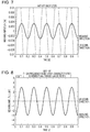
- a control characteristic (weaving trajectory) when the articulated robot 1 is controlled by using the elastic-deformation-compensation control device 10 with the above-described configuration is described.
- Fig. 3 shows a weaving trajectory when a high-frequency cutoff characteristic equivalent to that of the first dynamic characteristic calculation unit 300 is given as the high-frequency cutoff characteristic of the second dynamic characteristic calculation unit 400.
- Fig. 4 is a control block diagram of the most typical articulated robot. As shown in Fig. 4 , this control block is formed of a position control unit (Gp), a speed control unit (Gv), and a current control unit.
- the position control unit controls a joint angle by feedback control, controls the angle deviation by proportional control (P control), and gives the obtained value as a speed command to the speed control unit.
- the speed control unit controls a joint-angle speed by feedback control, controls the deviation with respect to the given speed command by proportional integral control (PI control), and gives the obtained value as a current control command to the current control unit.
- the current control unit controls motor current based on the given current control command.
- the component Since the articulated robot has a low natural frequency of a machine, to prevent a component that excites the natural oscillation from being contained in the target value, the component is restricted by filter processing in the first dynamic characteristic calculation unit (dynamic characteristic 1) etc. shown in Fig. 4 .
- an interference torque acts on each link between axes as a nonlinear term c including a gravity term etc. Since the link and the motor are coupled through the reduction gear that acts as a spring element, the axial force acts as action and reaction on the link and the motor. Particularly in the weaving operation of the welding robot, since it is required to swing the welding torch in a desirable direction with a desirable amplitude without an up-down deflection (without a motion generated in the up-down direction), dynamic control with very high accuracy is required. Owing to this, the influence of the axial force and elastic deformation is significantly large.
- Fig. 5 shows a weaving trajectory when an articulated robot is controlled by the control device shown in the control block of Fig. 4 .
- the nonlinear term, axial force, and elastic deformation act, a motion in the up-down direction is generated, and this is not desirable as the weaving motion.
- the axial force is calculated on a target-value basis, and may be compensated by feedforward compensation.
- Fig. 6 is a control block diagram that provides nonlinear feedforward compensation according to related art, on a target-value basis with regard to such consideration.
- Fig. 7 shows a weaving trajectory when an articulated robot is controlled by the control device shown in the control block of Fig. 6 . Since this is the feedforward compensation on a target-value basis, the feedforward timing is deviated due to the influence of a phase delay, and the compensation rather worsens the motion in the up-down direction.
- phase characteristic and gain characteristic of a feedback controller are different depending on each axis, it has been difficult to align the phases of feedforward control or the like.
- axial force torque compensation and elastic deformation compensation like those described above almost have not been in practical use, and it has been difficult to restrict the influence of elastic deformation or the like.
- the higher-order CPU executes nonlinear feedforward calculation. Since the calculation of the nonlinear term is complicated and the calculation amount is large, it is difficult to execute calculation in the servo controller. Hence, the calculation is typically executed on a target-value basis in the higher-order CPU.
- the result (weaving trajectory) of the elastic-deformation-compensation control device 10 has an up-down motion component generated as shown in Fig. 3 ; however, the up-down motion component is markedly restricted.
- Fig. 3 shows the result when the high-frequency cutoff characteristic in the second dynamic characteristic calculation unit 400 is set to be equal to the high-frequency cutoff characteristic in the first dynamic characteristic calculation unit 300.
- the first dynamic characteristic calculation unit 300 restricts the high frequency containing the natural oscillation component contained in the joint-angle command value ⁇ lc. Further, the second dynamic characteristic calculation unit 400 can restrict the high frequency containing the natural oscillation component contained in the axial force torque fc. Accordingly, the oscillation resulted from the nonlinear term according to the aforementioned related art is restricted.
- the elastic-deformation-compensation control device in the articulated robot, the influence of elastic deformation of each axis is compensated and a motion such as weaving is enabled with high trajectory accuracy.
- the elastic-deformation-compensation control device differs from the elastic-deformation-compensation control device 10 according to the above-described first embodiment in the method of giving the first dynamic characteristic calculation unit 300.
- Other configuration is similar to that of the first embodiment, and hence the part redundant to the above-described configuration is not repeated this time.
- the high-frequency cutoff characteristic equal to or higher than that of the first dynamic characteristic calculation unit 300 is given to the second dynamic characteristic calculation unit 400.
- a high-frequency cut off characteristic is given to the second dynamic characteristic calculation unit 400 such that the second dynamic characteristic calculation unit 400 has a very high high-frequency cutoff characteristic similarly to the first embodiment.
- a high-frequency cutoff characteristic is given to the first dynamic characteristic calculation unit 300 as a characteristic obtained by multiplying the dynamic characteristic of the second dynamic characteristic calculation unit 400 by the reverse characteristic of a feedback characteristic expected for servo control for each axis. This represents that the characteristic of the first dynamic characteristic calculation unit 300 is given to correspond to a characteristic obtained by dividing the characteristic in the second dynamic characteristic calculation unit 400 by the feedback control dynamic characteristic.
- the first dynamic characteristic calculation unit 300 is given by Expression (2) as follows.
- dynamic characteristic 2 / servo FB control dynamic characteristic ⁇ current control characteristic dynamic characteristic 2 ⁇ J m ⁇ s 3 + current control characteristic ⁇ Gv ⁇ s 2 + Gp ⁇ Gv + Gi ⁇ s + Gp ⁇ Gi Gp ⁇ Gv ⁇ s + Gp ⁇ Gi
- Fig. 8 shows a weaving trajectory when the first dynamic characteristic calculation unit 300 and the second dynamic characteristic calculation unit 400 are given as described above. As shown in Fig. 8 , in the weaving trajectory by the elastic-deformation-compensation control device according to this embodiment, it is found that the oscillation in the up-down direction is further restricted as compared with the weaving trajectory ( Fig. 3 ) according to the first embodiment.
- the elastic-deformation-compensation control device in the articulated robot, the influence of elastic deformation of each axis is compensated and a motion such as weaving is enabled with further high trajectory accuracy.
- the characteristic of the second dynamic characteristic calculation unit 400 is given as a desirable dynamic characteristic (having a very high high-frequency cutoff characteristic).
- the characteristic of the second dynamic characteristic calculation unit 400 is given as a characteristic obtained by dividing the desirable dynamic characteristic by the current control characteristic. This represents that, if the current control characteristic of the motor-current control unit 520 is considered, the characteristic of the first dynamic characteristic calculation unit 300 is given to correspond to a characteristic obtained by dividing the characteristic in the second dynamic characteristic calculation unit 400 by the feedback control dynamic characteristic and multiplying the divided value by the current control characteristic.
- Fig. 9 is a control block diagram when the characteristics of the first dynamic characteristic calculation unit 300 and the second dynamic characteristic calculation unit 400 are given as described above. As shown in Fig. 9 , the characteristic of a second dynamic characteristic calculation unit 2400 in an elastic-deformation-compensation control device 20 is obtained by multiplying a desirable dynamic characteristic 2410 by a reverse characteristic 2420 of the current control characteristic.
- the current control characteristic of the motor-current control unit 520 is considered, the influence of elastic deformation of each axis is compensated, and a motion such as weaving is enabled with further high trajectory accuracy.
- the elastic-deformation-compensation control device differs from the elastic-deformation-compensation control device 10 according to the above-described first embodiment in the method of giving the first dynamic characteristic calculation unit 300.
- Other configuration is similar to that of the first embodiment, and hence the part redundant to the above-described configuration is not repeated this time.
- Expression (1) is modified to Expression (5) as follows.
- Expression (2) that gives the first dynamic characteristic calculation unit 300 is modified to Expression (6) as follows.
- dynamic characteristic 2 ⁇ J m ⁇ s 3 + Gv ⁇ s 2 + Gp ⁇ Gv + Gi ⁇ s + Gp ⁇ Gi Gp ⁇ Gv ⁇ s + Gp ⁇ Gi
- the cutoff frequency in the second dynamic characteristic calculation unit 400 is set to be lower than the cutoff frequency of the first dynamic characteristic calculation unit 300 and the characteristic of the first dynamic characteristic calculation unit 300 is given to correspond to a characteristic obtained by dividing the characteristic in the second dynamic characteristic calculation unit 400 by a feedback control dynamic characteristic (servo FB control dynamic characteristic).
- servo FB control dynamic characteristic a feedback control dynamic characteristic
- the feedback control dynamic characteristic from the motor-angle target value ⁇ md to the actual motor angle ⁇ m in the state without an axial force among the respective axes is calculated based on a parameter including at least one of a position feedback gain and a speed feedback gain.
- Fig. 10 shows a weaving trajectory when the first dynamic characteristic calculation unit 300 and the second dynamic characteristic calculation unit 400 are given as described above.
- the performance of the weaving trajectory in this embodiment is not as good as the performance of the weaving trajectory ( Fig. 8 ) according to the second embodiment.
- performance sufficient for practical use is exhibited as compared with related art.
- the calculation time can be reduced while the performance sufficient for practical use is satisfied.
- the elastic-deformation-compensation control device differs from the elastic-deformation-compensation control device 10 according to the above-described first embodiment in the method of giving the first dynamic characteristic calculation unit 300.
- Other configuration is similar to that of the first embodiment, and hence the part redundant to the above-described configuration is not repeated this time.
- the elastic-deformation-compensation control device is configured such that the phase delay of the first dynamic characteristic calculation unit 300 of an axis with a late response of the motor-angle control unit 510 is given to be shorter than the phase delay of the first dynamic characteristic calculation unit 300 of an axis with an early response of the motor-angle control unit 510.
- a desirable dynamic characteristic is given to each axis.
- the dynamic characteristics of the respective axes have to be aligned in an actual weaving operation.
- the same (common) desirable dynamic characteristic may be given to all axes.
- the same desirable dynamic characteristic is already given to all axes.
- Fig. 11 shows a weaving trajectory when the desirable dynamic characteristic of each axis is slightly changed. As shown in Fig. 11 , if the response to each axis is changed by changing the dynamic characteristic for each axis, it is found that an up-down motion is generated. That is, the results of the above-described first to third embodiments (and related art) are results when the responses of the respective axes are aligned. If the responses of the respective axes are not aligned, weaving accuracy is degraded.
- the desirable dynamic characteristics of all axes are the same.
- Expression (1) and Expression (2) since the "dynamic characteristic 1" is multiplied by the reverse characteristic of the servo FB control dynamic characteristic, the response of the "dynamic characteristic 1" of an axis with a late servo FB control dynamic characteristic is earlier than the response of the "dynamic characteristic 1" of an axis with an early servo FB control dynamic characteristic. Also, the response of the "dynamic characteristic 1" of an axis with an early servo FB control dynamic characteristic is later than the response of the "dynamic characteristic 1" of an axis with a late servo FB control dynamic characteristic.
- the elastic-deformation-compensation control device differs from the elastic-deformation-compensation control device 10 according to the above-described first embodiment in that speed feedforward control and/or acceleration feedforward control, which are not provided in the elastic-deformation-compensation control device 10, are added.
- Other configuration is similar to that of the first embodiment, and hence the part redundant to the above-described configuration is not repeated this time.
- the speed feedforward control and/or the acceleration feedforward control are not provided.
- an elastic-deformation-compensation control device 30 according to this embodiment has the speed feedforward control and the acceleration feedforward control.
- Fig. 12 is a block diagram of the elastic-deformation-compensation control device 30 according to the fifth embodiment.
- the elastic-deformation-compensation control device 30 has the speed feedforward control and the acceleration feedforward control.
- the elastic-deformation-compensation control device 30 includes a motor-angle control unit 3510 instead of the motor-angle control unit 510.
- Expression (1) is given by Expression (7) as follows.
- Gda and Gdv respectively denote an acceleration feedforward gain and a speed feedforward gain, and each take a value from 0 to 1.
- Jd denotes a prediction value of Jm.
- the current control characteristic can be also calculated from the current control gain and motor parameters (inductance and resistance).
- the speed feedforward control and the acceleration feedforward control are added, the influence of elastic deformation of each axis is compensated, and a motion such as weaving is enabled with high trajectory accuracy.
- a second dynamic characteristic calculation unit 4400 is arranged upstream and downstream of the axial force torque calculation unit 200 being the nonlinear term.
- a dynamic characteristic (21) 4410 is arranged upstream of the axial force torque calculation unit 200
- a dynamic characteristic (22) 4420 is arranged downstream of the axial force torque calculation unit 200.
- ⁇ le is an output value when the joint-angle command value ⁇ lc is input to the dynamic characteristic (21) 4410.
- An output value obtained when the axial force torque fc calculated by the axial force torque calculation unit 200 based on the value ⁇ le is input to the dynamic characteristic (22) 4420 is an axial force torque compensation value fd.
- the elastic-deformation-compensation control device in the articulated robot, the influence of elastic deformation of each axis is compensated by the second dynamic characteristic calculation unit arranged in a divided form, and a motion such as weaving is enabled with high trajectory accuracy.
- Figs. 14 and 15 are each a block diagram of an elastic-deformation-compensation control device according to this embodiment.
- the control block shown in Fig. 14 differs from the control block shown in Fig. 15 in the number and positions of inverse-conversion (inverse-Jacobian) elements.
- the dynamic characteristic is determined from a target value to an actual value by the "dynamic characteristic 2" (or “desirable dynamic characteristic”).
- the gain characteristic and phase characteristic in the period of the weaving operation can be inversely calculated.
- the elastic-deformation-compensation control device differs from the elastic-deformation-compensation control device 10 according to the above-described first embodiment in that a phase difference between an axial force torque calculation value or an elastic-deformation amount calculation value and a joint-angle command value is corrected.
- Other configuration is similar to that of the first embodiment, and hence the part redundant to the above-described configuration is not repeated this time.
- the following processing is executed.
- a motor-angle-command-value calculation unit 600 the phase difference between the axial force torque calculation value or the elastic-deformation amount calculation value and the joint-angle command value is corrected, and the motor-angle command value is calculated from the axial force torque calculation value or elastic-deformation amount calculation value after the phase correction and the joint-angle command value after the phase correction.
- the elastic-deformation-compensation control device is described in detail below.
- the speed and acceleration of the joint angle are required.
- the speed and acceleration calculated by differential processing are used.
- the axial force torque calculation unit 200 that calculates the axial force executes processing in a period dT, which is markedly later than the servo control period. Hence, the influence of phase delay due to the difference is significantly large, and phase correction is executed to align the phases.
- an elastic deformation amount ec is calculated by using the joint-angle command value ⁇ lc with the aligned phase, and when a motor command value is further calculated, the joint-angle command value ⁇ lc with the aligned phase is corrected by the elastic deformation amount ec.
- the motor-angle command value ⁇ mc may be calculated.
- the elastic-deformation-compensation control device configured as described below enables a motion such as weaving with high trajectory accuracy in an articulated robot, in which a motor and an arm are coupled through an elastically deformable reduction gear.
Claims (8)
- Elastische-Deformations-Kompensations-Regelungs- bzw. Steuerungsvorrichtung für einen Knickarmroboter, beinhaltend einen Motor und einen Arm, die durch ein elastisch verformbares Untersetzungsgetriebe in dem Knickarmroboter miteinander gekoppelt sind, ein an dem Knickarmroboter angebrachtes Werkzeug und eine Vielzahl an Gelenkachsen, wobei jede von dem Motor angetrieben wird, um das Werkzeug zu veranlassen, einen gewünschten Arbeitsablauf durchzuführen, wobei die Elastische-Deformations-Kompensations-Regelungs- bzw. Steuerungsvorrichtung umfasst:eine Gelenkwinkel-Befehlswert-Berechnungseinheit, die einen Gelenkwinkel-Befehlswert θlc jeder der Gelenkachsen berechnet, um den gewünschten Arbeitsablauf des Werkzeugs bereitzustellen, und den Gelenkwinkel-Befehlswert θlc ausgibt;eine Axialkraft-Drehmoment-Berechnungseinheit, die ein Axialkraft-Drehmoment fc berechnet, das erzeugt wird, wenn ein Arbeitsablauf nach dem Gelenkwinkel-Befehlswert θlc ausgeführt wird und auf jede der Gelenkachsen wirkt, aus dem Gelenkwinkel-Befehlswert θlc auf der Grundlage eines Dynamik-Modells, und den Axialkraft-Drehmoment fc ausgibt;eine Motorwinkel-Befehlswert-Berechnungseinheit, die einen Motorwinkel-Befehlswert θmc berechnet aus dem Gelenkwinkel-Befehlswert θlc und dem Axialkraft-Drehmoment fc, auf der Grundlage eines Parameters, der einen Steifigkeits-Parameter der Gelenkachse beinhaltet, und den Motorwinkel-Befehlswert θmc ausgibt;eine erste dynamischer-Kennwert-Berechnungseinheit, die einen Hochfrequenz-Grenzkennwert aufweist mit einer Grenzfrequenz, die geringer als eine natürliche Resonanzfrequenz des Knickarmroboters ist, Filterverarbeitung bzw. -vorgang des Motorwinkel-Befehlswerts θmc ausführt, und einen verarbeiteten Motorwinkel-Zielwert θmd ausgibt;eine Motorwinkel-Regel-bzw. Steuereinheit, die die Motorwinkel-Zielwert-Eingabe θmd als Zielwert für den Motor empfängt;eine zweite dynamischer-Kennwert-Berechnungseinheit, die einen Hochfrequenz-Grenzkennwert aufweist mit einer Grenzfrequenz, die geringer oder gleich der ersten dynamischen-Kennwert-Berechnungseinheit ist, Filterverarbeitung bzw. -vorgang mindestens einer aus einer Eingabe an die Axialkraft-Drehmoment-Berechnungseinheit und einer Ausgabe aus der Axialkraft-Drehmoment-Berechnungseinheit, und einen verarbeiteten Axialkraft-Drehmoment-Kompensationswert fd ausgibt; undeine Motorstrom-Regel-bzw. Steuereinheit, die einen Eingabewert als Zielwert empfängt, wobei der Axialkraft-Drehmoment-Kompensationswert fd zu einer Motor-Drehmoment-Befehlswert-Ausgabe aus der Motorwinkel-Regel-bzw. Steuereinheit hinzugerechnet wird.
- Elastische-Deformations-Kompensations-Regelungs- bzw. Steuerungsvorrichtung für einen Knickarmroboter nach Anspruch 1, wobei eine Phasenverzögerung der ersten dynamischen-Kennwert-Berechnungseinheit einer Achse mit einer späten Reaktion der Motorwinkel-Regel-bzw. Steuereinheit kürzer gesetzt ist als eine Phasenverzögerung der ersten dynamischen-Kennwert-Berechnungseinheit einer Achse mit einer frühen Reaktion der Motorwinkel-Regel-bzw. Steuereinheit.
- Elastische-Deformations-Kompensations-Regelungs- bzw. Steuerungsvorrichtung für einen Knickarmroboter nach Anspruch 1, wobei ein dynamischer Rückkopplungsregelung-Kennwert vom Motorwinkel-Zielwert θmd zu einem tatsächlichen Winkel θm in einem Zustand ohne eine Axialkraft unter den entsprechenden Achsen berechnet wird auf der Grundlage eines Parameters beinhaltend mindestens eine aus einer Positionsrückkopplungsverstärkung und einer Geschwindigkeitsrückkopplungsverstärkung, und
wobei die Grenzfrequenz in der zweiten dynamischen-Kennwert-Berechnungseinheit geringer gesetzt ist als die Grenzfrequenz in der ersten dynamischen-Kennwert-Berechnungseinheit, und der Kennwert der ersten dynamischen-Kennwert-Berechnungseinheit gegeben ist, um einem Kennwert zu entsprechen, der erhalten wird, indem der Kennwert in der zweiten dynamischen-Kennwert-Berechnungseinheit geteilt wird durch den dynamischen Rückkopplungsregelung-Kennwert. - Elastische-Deformations-Kompensations-Regelungs- bzw. Steuerungsvorrichtung für einen Knickarmroboter nach Anspruch 2, wobei ein dynamischer Rückkopplungsregelung-Kennwert von dem Motorwinkel-Zielwert θmd zu einem tatsächlichen Motorwinkel θmd in einem Zustand ohne eine Axialkraft unter den entsprechenden Achsen berechnet wird auf der Grundlage eines Parameters beinhaltend mindestens eine aus einer Positionsrückkopplungsverstärkung und einer Geschwindigkeitsrückkopplungsverstärkung, und wobei die Grenzfrequenz in der zweiten dynamischen-Kennwert-Berechnungseinheit geringer gesetzt ist als die Grenzfrequenz in der ersten dynamischen-Kennwert-Berechnungseinheit, und der Kennwert der ersten dynamischen-Kennwert-Berechnungseinheit gegeben ist, um einem Kennwert zu entsprechen, der erhalten wird, indem der Kennwert in der zweiten dynamischen-Kennwert-Berechnungseinheit geteilt wird durch den dynamischen Rückkopplungsregelung-Kennwert.
- Elastische-Deformations-Kompensations-Regelungs- bzw. Steuerungsvorrichtung für einen Knickarmroboter nach Anspruch 3, wobei, wenn ein Strom-Regel-bzw. Steuerungskennwert der Motorstrom-Regel-bzw. Steuereinheit betrachtet wird, der Kennwert der ersten dynamischen-Kennwert-Berechnungseinheit gegeben ist, um einem Kennwert zu entsprechen, der erhalten wird, indem der Kennwert in der zweiten dynamischen-Kennwert-Berechnungseinheit geteilt wird durch den dynamischen Rückkopplungsregelung-Kennwert und der geteilte Wert mit dem Strom-Regel-bzw. Steuerungskennwert multipliziert wird.
- Elastische-Deformations-Kompensations-Regelungs- bzw. Steuerungsvorrichtung für einen Knickarmroboter nach Anspruch 4, wobei, wenn ein Strom-Regel-bzw. Steuerungskennwert der Motorstrom-Regel-bzw. Steuereinheit betrachtet wird, der Kennwert der ersten dynamischen-Kennwert-Berechnungseinheit gegeben ist, um einem Kennwert zu entsprechen, der erhalten wird, indem der Kennwert in der zweiten dynamischen-Kennwert-Berechnungseinheit geteilt wird durch den Dynamischer Rückkopplungsregelung-Kennwert und der geteilte Wert mit der multipliziert wird.
- Elastische-Deformations-Kompensations-Regelungs- bzw. Steuerungsvorrichtung für einen Knickarmroboter nach einem der Ansprüche 1 bis 6, wobei, wenn ein Berechnungszeitraum in der Motorwinkel-Befehlswert-Berechnungseinheit später ist als ein Berechnungszeitraum in der Motorwinkel-Regelungs- bzw. Steuereinheit,
in der Motorwinkel-Befehlswert-Berechnungseinheit eine Phasenverzögerung zwischen einem Axialkraft-Drehmoment-Berechnungswert oder einem elastische Deformationsmengen-Berechnungswert und einem Gelenkwinkel- Befehlswert korrigiert wird, und ein Motorwinkel-Befehlswert berechnet wird aus dem Axialkraft-Drehmoment-Berechnungswert oder elastischen Deformationsmengen-Berechnungswert nach der Phasenkorrektur und dem Gelenkwinkel-Befehlswert nach der Phasenkorrektur. - Elastische-Deformations-Kompensations-Regelungs- bzw. Steuerungsvorrichtung für einen Knickarmroboter beinhaltend einen Motor und einen Arm, die durch ein elastisch verformbares Untersetzungsgetriebe in dem Knickarmroboter miteinander gekoppelt sind, ein an dem Knickarmroboter angebrachtes Werkzeug und eine Vielzahl an Gelenkachsen, wobei jede von dem Motor angetrieben wird, um das Werkzeug zu veranlassen, einen gewünschten Arbeitsablauf durchzuführen, wobei die Elastische-Deformations-Kompensations-Regelungs- bzw. Steuerungsvorrichtung umfasst:einen Gelenkwinkel-Befehlswert-Berechnungsschritt des Berechnens eines Gelenkwinkel-Befehlswerts θlc jeder der Gelenkachsen, um den gewünschten Arbeitsablauf des Werkzeugs bereitzustellen, und Ausgabe des Gelenkwinkel-Befehlswerts θlc;einen Axialkraft-Drehmoment-Berechnungsschritt des Berechnens eines Axialkraft-Drehmoments fc, das erzeugt wird, wenn ein Arbeitsablauf nach dem Gelenkwinkel-Befehlswert θlc ausgeführt wird und auf jede der Gelenkachsen wirkt, aus dem Gelenkwinkel-Befehlswert θlc auf der Grundlage eines Dynamik-Modells, und Ausgabe des Axialkraft-Drehmoments fc;einen Motorwinkel-Befehlswert-Berechnungsschritt des Berechnens eines Motorwinkel-Befehlswerts θmc aus dem Gelenkwinkel-Befehlswert θlc und dem Axialkraft-Drehmoment fc, auf der Grundlage eines Parameters, der einen Steifigkeits-Parameter der Gelenkachse beinhaltet, und Ausgabe des Motorwinkel-Befehlswerts θmc;einen ersten dynamischen-Kennwert-Berechnungsschritt, aufweisend eine Hochfrequenz-Grenzkennwert mit einer Grenzfrequenz, die geringer als eine natürliche Resonanzfrequenz des Knickarmroboters ist, Ausführen der Filterverarbeitung bzw. -vorgangs des Motorwinkel-Befehlswerts θmc, und Ausgabe eines verarbeiteten Motorwinkel-Zielwerts θmd;einen Motorwinkel-Regel-bzw. Steuerschritt des Empfangens der Motorwinkel-Zielwert-Eingabe θmd als für den Motor;einen zweiten dynamischen-Kennwert-Berechnungsschritt aufweisend einen Hochfrequenz-Grenzkennwert mit einer Grenzfrequenz, die geringer oder gleich dem ersten dynamischen-Kennwert-Berechnungsschritt ist, Ausführen der Filterverarbeitung bzw. -vorgangs an mindestens einem aus einer Eingabe an den Axialkraft-Drehmoment-Berechnungsschritt und einer Ausgabe aus dem Axialkraft-Drehmoment-Berechnungsschritt, und Ausgabe eines verarbeiteten Axialkraft-Drehmoment-Kompensationswert fd; undeinen Motorstrom-Regel-bzw. Steuerungsschritt des Empfangens einer Werteingabe als Zielwert, wobei der Axialkraft-Drehmoment-Kompensationswert fd zu einer Motor-Drehmoment-Befehlswert-Ausgabe aus dem Motorwinkel-Regel-bzw. Steuerschritt hinzugerechnet wird.
Applications Claiming Priority (2)
| Application Number | Priority Date | Filing Date | Title |
|---|---|---|---|
| JP2012123239A JP5374613B2 (ja) | 2012-05-30 | 2012-05-30 | 多関節ロボットの弾性変形補償制御装置および制御方法 |
| PCT/JP2013/065057 WO2013180223A1 (ja) | 2012-05-30 | 2013-05-30 | 多関節ロボットの弾性変形補償制御装置および制御方法 |
Publications (3)
| Publication Number | Publication Date |
|---|---|
| EP2857151A1 EP2857151A1 (de) | 2015-04-08 |
| EP2857151A4 EP2857151A4 (de) | 2016-07-20 |
| EP2857151B1 true EP2857151B1 (de) | 2017-07-05 |
Family
ID=49673410
Family Applications (1)
| Application Number | Title | Priority Date | Filing Date |
|---|---|---|---|
| EP13796876.4A Active EP2857151B1 (de) | 2012-05-30 | 2013-05-30 | Steuerungsvorrichtung für den ausgleich der elastischen deformation für einen schwenkroboter und steuerungsverfahren |
Country Status (6)
| Country | Link |
|---|---|
| US (1) | US9505131B2 (de) |
| EP (1) | EP2857151B1 (de) |
| JP (1) | JP5374613B2 (de) |
| KR (1) | KR101612218B1 (de) |
| CN (1) | CN104349873B (de) |
| WO (1) | WO2013180223A1 (de) |
Families Citing this family (24)
| Publication number | Priority date | Publication date | Assignee | Title |
|---|---|---|---|---|
| JP5409844B2 (ja) * | 2012-05-30 | 2014-02-05 | 株式会社神戸製鋼所 | 多関節ロボットの軌跡制御装置および制御方法 |
| JP5916583B2 (ja) * | 2012-10-19 | 2016-05-11 | 株式会社神戸製鋼所 | 多関節ロボットのウィービング制御装置 |
| JP5642214B2 (ja) * | 2013-02-15 | 2014-12-17 | 株式会社神戸製鋼所 | 多関節ロボットの弾性変形補償制御装置 |
| AT514116A1 (de) * | 2013-04-09 | 2014-10-15 | Ttcontrol Gmbh | Regelsystem und Verfahren zum Steuern der Orientierung eines Segments eines Manipulators |
| JP5897644B2 (ja) * | 2014-06-02 | 2016-03-30 | 株式会社神戸製鋼所 | ロボットの制御装置 |
| US9718187B2 (en) * | 2014-06-11 | 2017-08-01 | Canon Kabushiki Kaisha | Robot controlling method, robot apparatus, program, recording medium, and method for manufacturing assembly component |
| US9505132B1 (en) * | 2015-03-30 | 2016-11-29 | X Development Llc | Methods and systems for calibrating a sensor of a robotic device |
| EP3131202A1 (de) * | 2015-08-11 | 2017-02-15 | Siemens Aktiengesellschaft | Filterumschaltverfahren für eine maschinensteuerung |
| US10350766B2 (en) * | 2015-09-21 | 2019-07-16 | GM Global Technology Operations LLC | Extended-reach assist device for performing assembly tasks |
| DE102017000063B4 (de) * | 2016-01-14 | 2019-10-31 | Fanuc Corporation | Robotereinrichtung mit Lernfunktion |
| DE112016006602T5 (de) * | 2016-03-16 | 2018-12-13 | Mitsubishi Electric Corporation | Maschinenbewegungsbahnverlaufsmessvorrichtung |
| CN107538494A (zh) * | 2016-06-29 | 2018-01-05 | 沈阳新松机器人自动化股份有限公司 | 一种基于转矩传感器和编码器的机器人控制方法及系统 |
| JP6386501B2 (ja) * | 2016-08-12 | 2018-09-05 | ファナック株式会社 | レーザ加工ロボットシステム及びレーザ加工方法 |
| EP3530423B1 (de) * | 2016-10-24 | 2022-04-13 | Panasonic Intellectual Property Management Co., Ltd. | Verfahren und vorrichtung zum erkennen von anomalien eines codierers und robotersteuerungssystem |
| DE102017005581B4 (de) * | 2017-06-13 | 2019-02-21 | Kuka Deutschland Gmbh | Steuern eines Roboters |
| WO2019012942A1 (ja) * | 2017-07-11 | 2019-01-17 | パナソニックIpマネジメント株式会社 | ロボット制御装置 |
| CN108638056A (zh) * | 2018-04-13 | 2018-10-12 | 华南理工大学 | 基于柔体动力学模型的机器人关节振动分析与抑制方法 |
| JP7338960B2 (ja) * | 2018-09-27 | 2023-09-05 | ニデックインスツルメンツ株式会社 | サーボ制御装置及びサーボ制御方法 |
| CN110053050A (zh) * | 2019-04-22 | 2019-07-26 | 珠海格力智能装备有限公司 | 机器人轨迹精度的补偿方法及装置、存储介质、处理器 |
| CN110450171B (zh) * | 2019-09-09 | 2020-12-08 | 北京配天技术有限公司 | 焊接机器人及其摆动轨迹的规划方法 |
| CN111673611B (zh) * | 2020-05-26 | 2021-06-18 | 华中科技大学 | 飞机复材构件机器人磨抛加工弹性变形及振动抑制方法 |
| JP7126576B1 (ja) * | 2021-02-16 | 2022-08-26 | 株式会社牧野フライス製作所 | 送り軸の制御方法および装置 |
| JP2022127016A (ja) * | 2021-02-19 | 2022-08-31 | 株式会社神戸製鋼所 | バネ定数補正装置、該方法および該プログラム |
| CN114029787B (zh) * | 2021-11-08 | 2022-11-25 | 陕西科控技术产业研究院有限公司 | 一种半闭环控制方式下数控机床进给系统弹性变形补偿方法 |
Family Cites Families (19)
| Publication number | Priority date | Publication date | Assignee | Title |
|---|---|---|---|---|
| JPS61201304A (ja) * | 1985-03-04 | 1986-09-06 | Matsushita Electric Ind Co Ltd | ロボツトの位置制御法 |
| US4829219A (en) * | 1986-11-20 | 1989-05-09 | Unimation Inc. | Multiaxis robot having improved motion control through variable acceleration/deceleration profiling |
| JP2645004B2 (ja) * | 1987-02-27 | 1997-08-25 | 株式会社東芝 | 多自由度マニピユレータの制御装置 |
| JPH106261A (ja) * | 1996-06-18 | 1998-01-13 | Sony Corp | ロボット制御装置 |
| JPH10217173A (ja) * | 1997-02-07 | 1998-08-18 | Yaskawa Electric Corp | ロボットの非干渉化制御装置 |
| JP3981773B2 (ja) * | 1997-05-28 | 2007-09-26 | 株式会社安川電機 | ロボット制御装置 |
| JP3473834B2 (ja) * | 1999-11-29 | 2003-12-08 | 株式会社安川電機 | ロボットの制御装置 |
| EP1132790B1 (de) * | 2000-02-10 | 2003-06-18 | Fanuc Ltd | Steuervorrichtung für eine Maschine |
| JP3983577B2 (ja) * | 2002-03-26 | 2007-09-26 | 株式会社神戸製鋼所 | 推定装置を用いた制御装置 |
| JP4536349B2 (ja) * | 2003-09-22 | 2010-09-01 | パナソニック株式会社 | 弾性体アクチュエータを用いた多自由度のロボットアームの制御装置及び制御方法 |
| JP4223911B2 (ja) * | 2003-09-25 | 2009-02-12 | 株式会社神戸製鋼所 | 衝突検知方法及び衝突検知装置 |
| JP4192780B2 (ja) * | 2003-12-26 | 2008-12-10 | 株式会社安川電機 | ロボットの制御装置 |
| JP2008296310A (ja) * | 2007-05-30 | 2008-12-11 | Fanuc Ltd | 加工ロボットの制御装置 |
| EP2168728B1 (de) * | 2008-05-21 | 2017-07-05 | Panasonic Intellectual Property Management Co., Ltd. | Verfahren zur beurteilung von roboterfehlern |
| DE102009054112A1 (de) * | 2009-11-20 | 2011-05-26 | Kuka Roboter Gmbh | Verfahren und Vorrichtung zur Planung und/oder Steuerung einer Roboterapplikation |
| JP5214578B2 (ja) * | 2009-12-02 | 2013-06-19 | 本田技研工業株式会社 | 動力装置の制御装置 |
| CN102781633A (zh) * | 2010-01-15 | 2012-11-14 | 松下电器产业株式会社 | 弹性体致动器驱动机构的控制装置及控制方法、以及控制程序 |
| JP5409844B2 (ja) * | 2012-05-30 | 2014-02-05 | 株式会社神戸製鋼所 | 多関節ロボットの軌跡制御装置および制御方法 |
| JP5642214B2 (ja) * | 2013-02-15 | 2014-12-17 | 株式会社神戸製鋼所 | 多関節ロボットの弾性変形補償制御装置 |
-
2012
- 2012-05-30 JP JP2012123239A patent/JP5374613B2/ja active Active
-
2013
- 2013-05-30 WO PCT/JP2013/065057 patent/WO2013180223A1/ja active Application Filing
- 2013-05-30 CN CN201380028233.6A patent/CN104349873B/zh active Active
- 2013-05-30 EP EP13796876.4A patent/EP2857151B1/de active Active
- 2013-05-30 KR KR1020147033246A patent/KR101612218B1/ko active IP Right Grant
- 2013-05-30 US US14/403,320 patent/US9505131B2/en active Active
Also Published As
| Publication number | Publication date |
|---|---|
| JP2013248681A (ja) | 2013-12-12 |
| KR20150006017A (ko) | 2015-01-15 |
| EP2857151A4 (de) | 2016-07-20 |
| JP5374613B2 (ja) | 2013-12-25 |
| CN104349873B (zh) | 2015-11-25 |
| KR101612218B1 (ko) | 2016-04-12 |
| US9505131B2 (en) | 2016-11-29 |
| US20150105905A1 (en) | 2015-04-16 |
| EP2857151A1 (de) | 2015-04-08 |
| WO2013180223A1 (ja) | 2013-12-05 |
| CN104349873A (zh) | 2015-02-11 |
Similar Documents
| Publication | Publication Date | Title |
|---|---|---|
| EP2857151B1 (de) | Steuerungsvorrichtung für den ausgleich der elastischen deformation für einen schwenkroboter und steuerungsverfahren | |
| EP2857152B1 (de) | Bahnsteuerungsvorrichtung für schwenkroboter und steuerungsverfahren | |
| EP3162658A1 (de) | Lenksteuerungsvorrichtung | |
| WO2014061681A1 (ja) | 多関節ロボットのウィービング制御装置 | |
| EP2957395B1 (de) | Steuerungsvorrichtung zur kompensation der elastischen verformung eines beweglichen roboters | |
| JP2005301508A (ja) | 制御装置 | |
| EP3643453A1 (de) | Robotersystem und verfahren zur steuerung des robotersystems | |
| EP3627693A1 (de) | Motorsteuerungssystem, verfahren zur steuerung des motorsteuerungssystems und robotersystem | |
| JP2021115999A (ja) | 操舵系装置の制御装置 | |
| JP4781000B2 (ja) | サーボ制御装置 | |
| Jung et al. | Analysis of position tracking in torque control of humanoid robots considering joint elasticity and time delay | |
| JP5868266B2 (ja) | 多関節ロボットの弾性変形補償制御装置および制御方法 | |
| JP2020179832A (ja) | 転舵制御装置 | |
| CN112247984B (zh) | 一种变刚度关节轨迹跟踪控制方法 |
Legal Events
| Date | Code | Title | Description |
|---|---|---|---|
| PUAI | Public reference made under article 153(3) epc to a published international application that has entered the european phase |
Free format text: ORIGINAL CODE: 0009012 |
|
| 17P | Request for examination filed |
Effective date: 20141211 |
|
| AK | Designated contracting states |
Kind code of ref document: A1 Designated state(s): AL AT BE BG CH CY CZ DE DK EE ES FI FR GB GR HR HU IE IS IT LI LT LU LV MC MK MT NL NO PL PT RO RS SE SI SK SM TR |
|
| AX | Request for extension of the european patent |
Extension state: BA ME |
|
| DAX | Request for extension of the european patent (deleted) | ||
| RA4 | Supplementary search report drawn up and despatched (corrected) |
Effective date: 20160622 |
|
| RIC1 | Information provided on ipc code assigned before grant |
Ipc: B23K 9/12 20060101ALI20160616BHEP Ipc: G05B 19/4093 20060101ALI20160616BHEP Ipc: B23K 9/095 20060101ALI20160616BHEP Ipc: B25J 9/10 20060101AFI20160616BHEP |
|
| GRAP | Despatch of communication of intention to grant a patent |
Free format text: ORIGINAL CODE: EPIDOSNIGR1 |
|
| INTG | Intention to grant announced |
Effective date: 20170103 |
|
| GRAS | Grant fee paid |
Free format text: ORIGINAL CODE: EPIDOSNIGR3 |
|
| GRAA | (expected) grant |
Free format text: ORIGINAL CODE: 0009210 |
|
| AK | Designated contracting states |
Kind code of ref document: B1 Designated state(s): AL AT BE BG CH CY CZ DE DK EE ES FI FR GB GR HR HU IE IS IT LI LT LU LV MC MK MT NL NO PL PT RO RS SE SI SK SM TR |
|
| REG | Reference to a national code |
Ref country code: GB Ref legal event code: FG4D |
|
| REG | Reference to a national code |
Ref country code: CH Ref legal event code: EP |
|
| REG | Reference to a national code |
Ref country code: AT Ref legal event code: REF Ref document number: 906279 Country of ref document: AT Kind code of ref document: T Effective date: 20170715 |
|
| REG | Reference to a national code |
Ref country code: IE Ref legal event code: FG4D |
|
| REG | Reference to a national code |
Ref country code: DE Ref legal event code: R096 Ref document number: 602013023184 Country of ref document: DE |
|
| REG | Reference to a national code |
Ref country code: NL Ref legal event code: FP |
|
| REG | Reference to a national code |
Ref country code: AT Ref legal event code: MK05 Ref document number: 906279 Country of ref document: AT Kind code of ref document: T Effective date: 20170705 |
|
| REG | Reference to a national code |
Ref country code: LT Ref legal event code: MG4D |
|
| PG25 | Lapsed in a contracting state [announced via postgrant information from national office to epo] |
Ref country code: SE Free format text: LAPSE BECAUSE OF FAILURE TO SUBMIT A TRANSLATION OF THE DESCRIPTION OR TO PAY THE FEE WITHIN THE PRESCRIBED TIME-LIMIT Effective date: 20170705 Ref country code: FI Free format text: LAPSE BECAUSE OF FAILURE TO SUBMIT A TRANSLATION OF THE DESCRIPTION OR TO PAY THE FEE WITHIN THE PRESCRIBED TIME-LIMIT Effective date: 20170705 Ref country code: AT Free format text: LAPSE BECAUSE OF FAILURE TO SUBMIT A TRANSLATION OF THE DESCRIPTION OR TO PAY THE FEE WITHIN THE PRESCRIBED TIME-LIMIT Effective date: 20170705 Ref country code: NO Free format text: LAPSE BECAUSE OF FAILURE TO SUBMIT A TRANSLATION OF THE DESCRIPTION OR TO PAY THE FEE WITHIN THE PRESCRIBED TIME-LIMIT Effective date: 20171005 Ref country code: LT Free format text: LAPSE BECAUSE OF FAILURE TO SUBMIT A TRANSLATION OF THE DESCRIPTION OR TO PAY THE FEE WITHIN THE PRESCRIBED TIME-LIMIT Effective date: 20170705 Ref country code: HR Free format text: LAPSE BECAUSE OF FAILURE TO SUBMIT A TRANSLATION OF THE DESCRIPTION OR TO PAY THE FEE WITHIN THE PRESCRIBED TIME-LIMIT Effective date: 20170705 |
|
| PG25 | Lapsed in a contracting state [announced via postgrant information from national office to epo] |
Ref country code: GR Free format text: LAPSE BECAUSE OF FAILURE TO SUBMIT A TRANSLATION OF THE DESCRIPTION OR TO PAY THE FEE WITHIN THE PRESCRIBED TIME-LIMIT Effective date: 20171006 Ref country code: ES Free format text: LAPSE BECAUSE OF FAILURE TO SUBMIT A TRANSLATION OF THE DESCRIPTION OR TO PAY THE FEE WITHIN THE PRESCRIBED TIME-LIMIT Effective date: 20170705 Ref country code: LV Free format text: LAPSE BECAUSE OF FAILURE TO SUBMIT A TRANSLATION OF THE DESCRIPTION OR TO PAY THE FEE WITHIN THE PRESCRIBED TIME-LIMIT Effective date: 20170705 Ref country code: PL Free format text: LAPSE BECAUSE OF FAILURE TO SUBMIT A TRANSLATION OF THE DESCRIPTION OR TO PAY THE FEE WITHIN THE PRESCRIBED TIME-LIMIT Effective date: 20170705 Ref country code: RS Free format text: LAPSE BECAUSE OF FAILURE TO SUBMIT A TRANSLATION OF THE DESCRIPTION OR TO PAY THE FEE WITHIN THE PRESCRIBED TIME-LIMIT Effective date: 20170705 Ref country code: BG Free format text: LAPSE BECAUSE OF FAILURE TO SUBMIT A TRANSLATION OF THE DESCRIPTION OR TO PAY THE FEE WITHIN THE PRESCRIBED TIME-LIMIT Effective date: 20171005 Ref country code: IS Free format text: LAPSE BECAUSE OF FAILURE TO SUBMIT A TRANSLATION OF THE DESCRIPTION OR TO PAY THE FEE WITHIN THE PRESCRIBED TIME-LIMIT Effective date: 20171105 |
|
| REG | Reference to a national code |
Ref country code: DE Ref legal event code: R097 Ref document number: 602013023184 Country of ref document: DE |
|
| REG | Reference to a national code |
Ref country code: FR Ref legal event code: PLFP Year of fee payment: 6 |
|
| PG25 | Lapsed in a contracting state [announced via postgrant information from national office to epo] |
Ref country code: DK Free format text: LAPSE BECAUSE OF FAILURE TO SUBMIT A TRANSLATION OF THE DESCRIPTION OR TO PAY THE FEE WITHIN THE PRESCRIBED TIME-LIMIT Effective date: 20170705 Ref country code: RO Free format text: LAPSE BECAUSE OF FAILURE TO SUBMIT A TRANSLATION OF THE DESCRIPTION OR TO PAY THE FEE WITHIN THE PRESCRIBED TIME-LIMIT Effective date: 20170705 Ref country code: CZ Free format text: LAPSE BECAUSE OF FAILURE TO SUBMIT A TRANSLATION OF THE DESCRIPTION OR TO PAY THE FEE WITHIN THE PRESCRIBED TIME-LIMIT Effective date: 20170705 |
|
| PLBE | No opposition filed within time limit |
Free format text: ORIGINAL CODE: 0009261 |
|
| STAA | Information on the status of an ep patent application or granted ep patent |
Free format text: STATUS: NO OPPOSITION FILED WITHIN TIME LIMIT |
|
| PG25 | Lapsed in a contracting state [announced via postgrant information from national office to epo] |
Ref country code: SM Free format text: LAPSE BECAUSE OF FAILURE TO SUBMIT A TRANSLATION OF THE DESCRIPTION OR TO PAY THE FEE WITHIN THE PRESCRIBED TIME-LIMIT Effective date: 20170705 Ref country code: SK Free format text: LAPSE BECAUSE OF FAILURE TO SUBMIT A TRANSLATION OF THE DESCRIPTION OR TO PAY THE FEE WITHIN THE PRESCRIBED TIME-LIMIT Effective date: 20170705 Ref country code: EE Free format text: LAPSE BECAUSE OF FAILURE TO SUBMIT A TRANSLATION OF THE DESCRIPTION OR TO PAY THE FEE WITHIN THE PRESCRIBED TIME-LIMIT Effective date: 20170705 |
|
| 26N | No opposition filed |
Effective date: 20180406 |
|
| PG25 | Lapsed in a contracting state [announced via postgrant information from national office to epo] |
Ref country code: SI Free format text: LAPSE BECAUSE OF FAILURE TO SUBMIT A TRANSLATION OF THE DESCRIPTION OR TO PAY THE FEE WITHIN THE PRESCRIBED TIME-LIMIT Effective date: 20170705 |
|
| REG | Reference to a national code |
Ref country code: CH Ref legal event code: PL |
|
| GBPC | Gb: european patent ceased through non-payment of renewal fee |
Effective date: 20180530 |
|
| PG25 | Lapsed in a contracting state [announced via postgrant information from national office to epo] |
Ref country code: MC Free format text: LAPSE BECAUSE OF FAILURE TO SUBMIT A TRANSLATION OF THE DESCRIPTION OR TO PAY THE FEE WITHIN THE PRESCRIBED TIME-LIMIT Effective date: 20170705 |
|
| REG | Reference to a national code |
Ref country code: IE Ref legal event code: MM4A |
|
| PG25 | Lapsed in a contracting state [announced via postgrant information from national office to epo] |
Ref country code: LI Free format text: LAPSE BECAUSE OF NON-PAYMENT OF DUE FEES Effective date: 20180531 Ref country code: CH Free format text: LAPSE BECAUSE OF NON-PAYMENT OF DUE FEES Effective date: 20180531 |
|
| PG25 | Lapsed in a contracting state [announced via postgrant information from national office to epo] |
Ref country code: LU Free format text: LAPSE BECAUSE OF NON-PAYMENT OF DUE FEES Effective date: 20180530 |
|
| PG25 | Lapsed in a contracting state [announced via postgrant information from national office to epo] |
Ref country code: GB Free format text: LAPSE BECAUSE OF NON-PAYMENT OF DUE FEES Effective date: 20180530 Ref country code: IE Free format text: LAPSE BECAUSE OF NON-PAYMENT OF DUE FEES Effective date: 20180530 |
|
| PG25 | Lapsed in a contracting state [announced via postgrant information from national office to epo] |
Ref country code: MT Free format text: LAPSE BECAUSE OF NON-PAYMENT OF DUE FEES Effective date: 20180530 |
|
| PG25 | Lapsed in a contracting state [announced via postgrant information from national office to epo] |
Ref country code: TR Free format text: LAPSE BECAUSE OF FAILURE TO SUBMIT A TRANSLATION OF THE DESCRIPTION OR TO PAY THE FEE WITHIN THE PRESCRIBED TIME-LIMIT Effective date: 20170705 |
|
| PG25 | Lapsed in a contracting state [announced via postgrant information from national office to epo] |
Ref country code: PT Free format text: LAPSE BECAUSE OF FAILURE TO SUBMIT A TRANSLATION OF THE DESCRIPTION OR TO PAY THE FEE WITHIN THE PRESCRIBED TIME-LIMIT Effective date: 20170705 |
|
| PG25 | Lapsed in a contracting state [announced via postgrant information from national office to epo] |
Ref country code: HU Free format text: LAPSE BECAUSE OF FAILURE TO SUBMIT A TRANSLATION OF THE DESCRIPTION OR TO PAY THE FEE WITHIN THE PRESCRIBED TIME-LIMIT; INVALID AB INITIO Effective date: 20130530 Ref country code: CY Free format text: LAPSE BECAUSE OF FAILURE TO SUBMIT A TRANSLATION OF THE DESCRIPTION OR TO PAY THE FEE WITHIN THE PRESCRIBED TIME-LIMIT Effective date: 20170705 Ref country code: MK Free format text: LAPSE BECAUSE OF NON-PAYMENT OF DUE FEES Effective date: 20170705 |
|
| PG25 | Lapsed in a contracting state [announced via postgrant information from national office to epo] |
Ref country code: AL Free format text: LAPSE BECAUSE OF FAILURE TO SUBMIT A TRANSLATION OF THE DESCRIPTION OR TO PAY THE FEE WITHIN THE PRESCRIBED TIME-LIMIT Effective date: 20170705 |
|
| PGFP | Annual fee paid to national office [announced via postgrant information from national office to epo] |
Ref country code: DE Payment date: 20210505 Year of fee payment: 9 Ref country code: FR Payment date: 20210412 Year of fee payment: 9 |
|
| PGFP | Annual fee paid to national office [announced via postgrant information from national office to epo] |
Ref country code: BE Payment date: 20210415 Year of fee payment: 9 |
|
| REG | Reference to a national code |
Ref country code: DE Ref legal event code: R119 Ref document number: 602013023184 Country of ref document: DE |
|
| REG | Reference to a national code |
Ref country code: BE Ref legal event code: MM Effective date: 20220531 |
|
| PG25 | Lapsed in a contracting state [announced via postgrant information from national office to epo] |
Ref country code: FR Free format text: LAPSE BECAUSE OF NON-PAYMENT OF DUE FEES Effective date: 20220531 |
|
| PG25 | Lapsed in a contracting state [announced via postgrant information from national office to epo] |
Ref country code: DE Free format text: LAPSE BECAUSE OF NON-PAYMENT OF DUE FEES Effective date: 20221201 Ref country code: BE Free format text: LAPSE BECAUSE OF NON-PAYMENT OF DUE FEES Effective date: 20220531 |
|
| P01 | Opt-out of the competence of the unified patent court (upc) registered |
Effective date: 20230523 |
|
| PGFP | Annual fee paid to national office [announced via postgrant information from national office to epo] |
Ref country code: NL Payment date: 20230417 Year of fee payment: 11 |
|
| PGFP | Annual fee paid to national office [announced via postgrant information from national office to epo] |
Ref country code: IT Payment date: 20230412 Year of fee payment: 11 |