WO2019012942A1 - ロボット制御装置 - Google Patents
ロボット制御装置 Download PDFInfo
- Publication number
- WO2019012942A1 WO2019012942A1 PCT/JP2018/023611 JP2018023611W WO2019012942A1 WO 2019012942 A1 WO2019012942 A1 WO 2019012942A1 JP 2018023611 W JP2018023611 W JP 2018023611W WO 2019012942 A1 WO2019012942 A1 WO 2019012942A1
- Authority
- WO
- WIPO (PCT)
- Prior art keywords
- position command
- torque
- deflection
- robot
- correction value
- Prior art date
Links
Images


Classifications
-
- B—PERFORMING OPERATIONS; TRANSPORTING
- B25—HAND TOOLS; PORTABLE POWER-DRIVEN TOOLS; MANIPULATORS
- B25J—MANIPULATORS; CHAMBERS PROVIDED WITH MANIPULATION DEVICES
- B25J9/00—Programme-controlled manipulators
- B25J9/16—Programme controls
- B25J9/1628—Programme controls characterised by the control loop
- B25J9/1638—Programme controls characterised by the control loop compensation for arm bending/inertia, pay load weight/inertia
-
- B—PERFORMING OPERATIONS; TRANSPORTING
- B25—HAND TOOLS; PORTABLE POWER-DRIVEN TOOLS; MANIPULATORS
- B25J—MANIPULATORS; CHAMBERS PROVIDED WITH MANIPULATION DEVICES
- B25J9/00—Programme-controlled manipulators
- B25J9/16—Programme controls
- B25J9/1628—Programme controls characterised by the control loop
- B25J9/1635—Programme controls characterised by the control loop flexible-arm control
-
- B—PERFORMING OPERATIONS; TRANSPORTING
- B25—HAND TOOLS; PORTABLE POWER-DRIVEN TOOLS; MANIPULATORS
- B25J—MANIPULATORS; CHAMBERS PROVIDED WITH MANIPULATION DEVICES
- B25J9/00—Programme-controlled manipulators
- B25J9/16—Programme controls
- B25J9/1628—Programme controls characterised by the control loop
- B25J9/1633—Programme controls characterised by the control loop compliant, force, torque control, e.g. combined with position control
-
- B—PERFORMING OPERATIONS; TRANSPORTING
- B25—HAND TOOLS; PORTABLE POWER-DRIVEN TOOLS; MANIPULATORS
- B25J—MANIPULATORS; CHAMBERS PROVIDED WITH MANIPULATION DEVICES
- B25J9/00—Programme-controlled manipulators
- B25J9/16—Programme controls
- B25J9/1694—Programme controls characterised by use of sensors other than normal servo-feedback from position, speed or acceleration sensors, perception control, multi-sensor controlled systems, sensor fusion
-
- G—PHYSICS
- G05—CONTROLLING; REGULATING
- G05B—CONTROL OR REGULATING SYSTEMS IN GENERAL; FUNCTIONAL ELEMENTS OF SUCH SYSTEMS; MONITORING OR TESTING ARRANGEMENTS FOR SUCH SYSTEMS OR ELEMENTS
- G05B2219/00—Program-control systems
- G05B2219/30—Nc systems
- G05B2219/39—Robotics, robotics to robotics hand
- G05B2219/39178—Compensation inertia arms
-
- G—PHYSICS
- G05—CONTROLLING; REGULATING
- G05B—CONTROL OR REGULATING SYSTEMS IN GENERAL; FUNCTIONAL ELEMENTS OF SUCH SYSTEMS; MONITORING OR TESTING ARRANGEMENTS FOR SUCH SYSTEMS OR ELEMENTS
- G05B2219/00—Program-control systems
- G05B2219/30—Nc systems
- G05B2219/39—Robotics, robotics to robotics hand
- G05B2219/39186—Flexible joint
-
- G—PHYSICS
- G05—CONTROLLING; REGULATING
- G05B—CONTROL OR REGULATING SYSTEMS IN GENERAL; FUNCTIONAL ELEMENTS OF SUCH SYSTEMS; MONITORING OR TESTING ARRANGEMENTS FOR SUCH SYSTEMS OR ELEMENTS
- G05B2219/00—Program-control systems
- G05B2219/30—Nc systems
- G05B2219/39—Robotics, robotics to robotics hand
- G05B2219/39187—Coriolis and centripetal compensation
-
- G—PHYSICS
- G05—CONTROLLING; REGULATING
- G05B—CONTROL OR REGULATING SYSTEMS IN GENERAL; FUNCTIONAL ELEMENTS OF SUCH SYSTEMS; MONITORING OR TESTING ARRANGEMENTS FOR SUCH SYSTEMS OR ELEMENTS
- G05B2219/00—Program-control systems
- G05B2219/30—Nc systems
- G05B2219/39—Robotics, robotics to robotics hand
- G05B2219/39189—Compensate for dead weight of tool as function of inclination tool
-
- G—PHYSICS
- G05—CONTROLLING; REGULATING
- G05B—CONTROL OR REGULATING SYSTEMS IN GENERAL; FUNCTIONAL ELEMENTS OF SUCH SYSTEMS; MONITORING OR TESTING ARRANGEMENTS FOR SUCH SYSTEMS OR ELEMENTS
- G05B2219/00—Program-control systems
- G05B2219/30—Nc systems
- G05B2219/39—Robotics, robotics to robotics hand
- G05B2219/39194—Compensation gravity
Definitions
- the present disclosure relates to a robot control device, and more particularly to control of a robot that corrects positional deviation or the like of a robot arm due to bending of a reduction gear.
- the demand for performing laser processing has been increasing from the viewpoint of shortening tact and accuracy of finishing.
- the laser output device is often mounted on the tip of the robot arm of the articulated robot for processing.
- a conventional articulated robot operates a robot arm by driving a servomotor to rotate a joint axis.
- the driving force of the servomotor is transmitted to the joint shaft via a reduction gear connected to the servomotor.
- a phenomenon of so-called bending occurs in which the robot arm tip position instructed to the servomotor and the actual robot arm tip position deviate due to the spring component of the reduction gear.
- gravity torque a force due to gravity
- interference torque a force due to interference from another joint axis
- a deflection correction has been proposed in which a correction value based on the amount of deflection is obtained by calculation, and the correction value is added to the position command (for example, see Patent Document 1). Specifically, external force torque applied to the reduction gear of each joint shaft is calculated, and divided by the spring constant of the reduction gear to obtain the amount of deflection.
- the amount of deflection corresponds to the amount of displacement of the tip end position of the robot arm or the amount of displacement of the angle of the joint axis caused by the deflection.
- the correction value based on the deflection amount is added to the position command in the reverse direction.
- the behavior of the deflection generated in the reduction gear differs between the component due to the gravity torque and the component due to the interference torque. Therefore, when the correction is directly performed from the external force torque in which the gravity torque and the interference torque are added as in the above-mentioned prior art, there is a possibility that the deflection correction may not be correctly performed.
- This indication is made in view of this point, and the object is to provide the robot control device which can correct the position gap of a robot arm accurately, reducing the influence of the bending of a reduction gear.
- a robot control device individually obtains a gravity torque and an interference torque applied to a reduction gear connected to each joint axis.
- the deflection correction value is obtained based on each of the obtained gravity torque and interference torque. These values are used to correct the position command given to the motor.
- a robot control device that performs motion control of a robot arm having a joint axis driven via a reduction gear connected to a servomotor,
- the main control unit for transmitting a command, a servo control unit, and deflection correction means for correcting positional deviation of the robot arm due to deflection of the reduction gear, wherein the deflection correction means is an external force for generating the deflection of the reduction gear
- gravity torque is calculated based on the position command
- the first position command correction value calculation means for obtaining the first position command correction value based on the gravity torque, and of the external force torque based on the position command and the gravity torque
- second position command correction value calculation means for calculating an interference torque generated by the interference received by the joint axis and obtaining a second position command correction value based on the interference torque
- Control unit is characterized by driving the servo motor based on the new position command obtained by the first position command correction value and a second position command
- the second position command correction value is preferably a value in which the amplitude and the phase of the deflection correction value obtained based on the interference torque are respectively compensated.
- a robot control device is a robot control device that performs motion control of a robot arm having a joint axis driven via a reduction gear connected to a servomotor, and transmits a position command.
- the main control unit, the servo control unit, and deflection correction means for correcting positional deviation of the robot arm due to bending of the reduction gear, the deflection correction means generates external force torque that generates deflection of the robot arm based on the position command.
- the first position command correction value calculation means for calculating the first position command correction value based on the gravity torque by calculating the gravity torque among them, and the interference generated by the joint axis among the external force torque based on the position command and the gravity torque
- Current compensation value computing means for computing the interference torque to be calculated and obtaining the current compensation value based on the interference torque
- the servo control section calculates the first position command correction value Servo based on a new motor current command obtained by adding a current compensation value to a motor current command generated based on the new position command. It is characterized by driving a motor.
- the current compensation value is preferably a value obtained by multiplying the amplitude and the phase of the deflection correction value obtained based on the interference torque with each other by a predetermined coefficient.
- the servomotor is one of n (n is an integer of 2 or more) servomotors, and the reduction gear is one of n reduction gears respectively connected to n servomotors.
- the joint axis is one of n joint axes respectively driven through n decelerators, and the servo control unit performs n servo control respectively driving n servo motors.
- the position command is one of n position commands for specifying the position of each of the n joint axes
- the deflection correction means is for the n servo control units.
- it is configured to correct for misalignment.
- the external force torque and the gravitational torque are respectively obtained by the dynamics calculation, and the interference torque is preferably obtained by subtracting the gravitational torque from the external force torque.
- the gravitational torque and the interference torque can be easily separated, and the positional deviation of the robot arm due to the bending can be corrected.
- the displacement due to the gravity torque and the deflection due to the interference torque from the other axis can be separated to correct the positional deviation of the robot arm with high accuracy.
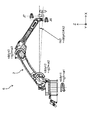
- FIG. 1 is a view showing the configuration of a vertical articulated six-axis robot.
- FIG. 2A is a diagram showing a frequency response characteristic of the amplitude of the transfer function with respect to the operating frequency of the main axis.
- FIG. 2B is a diagram showing the frequency response characteristic of the phase of the transfer function with respect to the operating frequency of the main axis.
- FIG. 2C is a diagram showing time waveforms of the position command ⁇ c and the actual position ⁇ L when a 5 Hz sine wave is given as the position command ⁇ c to the main axis.
- FIG. 3 is a view showing the configuration of a vertical articulated seven-axis robot in which a movable axis is added to the tip of the vertical articulated six-axis robot.
- FIG. 3 is a view showing the configuration of a vertical articulated seven-axis robot in which a movable axis is added to the tip of the vertical articulated six-axis robot.
- FIG. 4 is a view showing a time change of a trajectory of a tip of a robot arm of the vertical articulated seven-axis robot shown in FIG.
- FIG. 5A is a diagram showing a frequency response characteristic of the amplitude of the transfer function with respect to the operating frequency of the end of the robot arm.
- FIG. 5B is a diagram showing frequency response characteristics of the phase of the transfer function with respect to the operating frequency of the tip of the robot arm.
- FIG. 5C is a diagram showing time waveforms of the position command ⁇ c and the actual position ⁇ L when a 5 Hz sine wave is given as the position command ⁇ c to the tip of the robot arm.
- FIG. 5A is a diagram showing a frequency response characteristic of the amplitude of the transfer function with respect to the operating frequency of the end of the robot arm.
- FIG. 5B is a diagram showing frequency response characteristics of the phase of the transfer function with respect to the operating frequency of the tip of the robot arm.
- FIG. 5C is a diagram showing time wave
- FIG. 6 is a diagram showing a time change of the trajectory of the tip of the robot arm of the vertical articulated seven-axis robot when the reduction gear is bent.
- FIG. 7 is a schematic view for explaining the positional deviation of the tip of the robot arm caused by the external force torque.
- FIG. 8A is a diagram showing a frequency response characteristic of the amplitude of the transfer function with respect to the operating frequency of the main shaft when the reduction gear is bent.
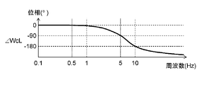
- FIG. 8B is a diagram showing the frequency response characteristic of the phase of the transfer function with respect to the operating frequency of the main shaft when the reduction gear is bent.
- FIG. 8A is a diagram showing a frequency response characteristic of the amplitude of the transfer function with respect to the operating frequency of the main shaft when the reduction gear is bent.
- FIG. 8B is a diagram showing the frequency response characteristic of the phase of the transfer function with respect to the operating frequency of the main shaft when the reduction gear is bent.
- FIG. 8C is a diagram showing time waveforms of the position command ⁇ c and the actual position ⁇ L when a sine wave of 0.5 Hz is given as the position command ⁇ c to the main axis.
- FIG. 8D is a diagram showing time waveforms of the position command ⁇ c and the actual position ⁇ L when a 5 Hz sine wave is given as the position command ⁇ c to the main axis.
- FIG. 9 is a functional block diagram related to position control of the vertical articulated seven-axis robot shown in FIG.
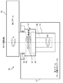
- FIG. 10 is a diagram for explaining the bending of the reduction gear in the robot mechanism.
- FIG. 11 is a block diagram of the load shown in FIG.
- FIG. 12 is a block diagram of a first servo control unit for comparison.
- FIG. 13 is a block diagram of the deflection correction block shown in FIG.
- FIG. 14 is a block diagram of a first servo control unit according to the first embodiment of the present disclosure.
- FIG. 15 is a block diagram of the deflection correction block shown in FIG.
- FIG. 16A is a diagram showing a frequency response characteristic of the amplitude of the transfer function with respect to the operating frequency of the main shaft according to the first embodiment.
- FIG. 16B is a diagram showing frequency response characteristics of the phase of the transfer function with respect to the operating frequency of the main shaft according to the first embodiment.
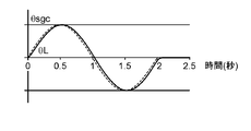
- FIG. 16C is a diagram showing time waveforms of the position command ⁇ c and the actual position ⁇ L when a sine wave of 0.5 Hz is given as the position command ⁇ c to the main axis.
- FIG. 16A is a diagram showing a frequency response characteristic of the amplitude of the transfer function with respect to the operating frequency of the main shaft according to the first embodiment.
- FIG. 16B is a diagram showing
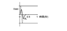
- FIG. 16D is a diagram showing time waveforms of the position command ⁇ c and the actual position ⁇ L when a 5 Hz sine wave is given as the position command ⁇ c to the main axis.
- FIG. 17 is a block diagram of a first servo control unit according to a second embodiment of the present disclosure.
- FIG. 18 is a block diagram of the deflection correction block shown in FIG.
- the external force torque includes torque due to gravity and interference torque received from other joint axes.
- the present inventors have found that the influence on the position command after deflection correction, specifically, the response frequency is different between the gravity torque and the interference torque.
- the operation of the vertical articulated robot will be described as an example.
- FIG. 1 shows the configuration of a conventional vertical articulated robot used in laser welding and cutting.
- the vertical articulated six-axis robot 1 has a robot arm 2 and joint axes J1 to J6.
- the robot arm 2 is divided into a plurality of portions, and joint portions of the respective portions are provided with joint axes J1 to J6.
- the joint axes J1 to J6 respectively connect servomotors (not shown) via reduction gears (not shown).
- the robot control device 20 drives the servomotors according to the position command ⁇ c (see FIG. 10) to rotate the joint axes J1 to J6 by desired amounts, respectively, to control the movement and posture of the robot arm 2.
- a laser output device 3 is attached to the end of the robot arm 2.
- a laser light source (not shown) for generating a laser beam 4 and an optical fiber (not shown) for guiding the laser beam 4 are connected to the laser output device 3.
- the vertical articulated six-axis robot 1 has a total of six joint axes including three main axes J1 to J3 which determine the overall posture and three wrists J4 to J6 which determine the direction of the tip.
- the X, Y, and Z directions shown in FIG. 1 may be used to describe the position and movement of the vertical articulated six-axis robot 1.
- the laser output device 3 has, for example, a mass of about 5 kg.
- the posture of the robot arm 2 in the vertical articulated six-axis robot 1 having six axes, that is, the angle of each joint axis is uniquely determined. As described above, since the control redundancy of the joint axes is zero, all joint axes operate when cutting with a circular locus.
- each joint axis receives and operates a sinusoidal position command ⁇ c corresponding to the operating frequency.
- a frequency at which each joint axis can respond in response to the position command ⁇ c is defined as a position response frequency
- the position of each joint axis (hereinafter referred to as an actual position) is set as ⁇ L.
- the position command ⁇ c indicates an angle command that instructs the rotation angle amount of each joint axis
- the actual position ⁇ L indicates a rotation angle amount at which each joint axis actually rotates.
- the position response frequency is determined by the natural vibration frequency of each joint axis constituting the vertical articulated six-axis robot 1 and the characteristics of the control device (see FIG. 9) which drives each joint axis.
- a transfer function WcL until each joint axis reaches the actual position ⁇ L in response to the position command ⁇ c is defined by the following (formula 1).
- the position response frequency is the frequency at which the amplitude of the transfer function WcL is half (-6 dB) or the frequency at which the phase of the transfer function WcL is delayed by 90 °, whichever is lower.
- the position response frequency becomes minimum at an arm extension posture (inertia is maximum) and becomes about 5 Hz.
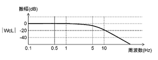
- FIGS. 2A and 2B show the response of the transfer function to the operating frequency of the main axis
- FIG. 2A shows the frequency response of the amplitude of the transfer function WcL
- FIG. 2B shows the frequency response of the phase of the transfer function WcL.
- FIG. 2C shows time waveforms of ⁇ c and ⁇ L when a 5 Hz sine wave is given as the position command ⁇ c to the main axis having the frequency characteristics shown in FIGS. 2A and 2B.
- the amplitude is half (-6 dB) and the phase is delayed by 90 °.
- the amplitude of the actual position ⁇ L is half of the position command ⁇ c, and the phase is delayed by 90 °.
- the wrist three axes J4 to J6 are smaller and lighter than the three main axes J1 to J3. Therefore, even if the laser output device 3 of about 5 kg is mounted, the three wrist axes J4 to J6 have a position response frequency of 10 Hz or more. Therefore, a new joint axis J7 may be added to the tip of the robot arm 2.
- the robot arm 2 is sufficient even at an operation frequency of 5 Hz or more by maintaining the stopped state of the main spindles 3 axes J1 to J3 and performing positioning and trajectory tracking operation with the wrist 3 axes J4 to J6 and the new joint axis J7. Position responsiveness can be realized. That is, the joint axes J1 to J5 are completely stopped so that the rotation center position 8 of the joint axis J6 does not move.
- FIG. 3 shows the configuration of a vertical articulated seven-axis robot in which a joint axis J7 parallel to the joint axis J6 at the tip is added.
- the vertical articulated seven-axis robot 6 can operate only the joint axes J6 and J7 of the tip portion to draw a desired trajectory such as a circle or an ellipse at the tip of the robot arm 2.
- FIG. 4 shows a time change of the trajectory of the end of the robot arm of the vertical articulated seven-axis robot 6 shown in FIG.
- the joint axes J1 to J5 of the robot arm 2 are driven to move the laser irradiation position 7 to the center of the target circular trajectory, and laser irradiation is started.
- the joint axes J6 and J7 are rotated in the respective rotational directions 9 and 10 so that the laser irradiation position 7 is moved in the + Y direction and put on the circular orbit.
- the joint axes J6 and J7 are rotated so that the laser irradiation position 7 moves along the circular orbit from time t3 to t5, and the laser irradiation is ended at time t6.
- FIGS. 5A and 5B show the response characteristic of the transfer function to the operating frequency at the end of the robot arm.
- FIG. 5A shows the frequency response characteristic of the amplitude of the transfer function WcL
- FIG. 5B shows the frequency response characteristic of the phase of the transfer function WcL.
- the tip of the robot arm indicates joint axes J6 and J7.
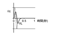
- 5C shows time waveforms of ⁇ c and ⁇ L when a 5 Hz sine wave is given as the position command ⁇ c to the robot arm having the frequency characteristics shown in FIGS. 5A and 5B.
- the position response frequency is higher than that of the main axis, for example, about 20 Hz.
- FIGS. 5A and 5B when the position response frequency is 20 Hz, the amplitude is halved (-6 dB) and the phase is delayed by 90 °.
- FIG. 5C when the frequency of the position command ⁇ c is 5 hz, the attenuation of the amplitude and the delay of the phase are small in the actual position ⁇ L, and the actual position ⁇ L is better for the position command ⁇ c than in the case shown in FIG. It is understood that it is following.
- the tip of the robot arm 2 can draw a circular locus substantially as instructed.
- the inventors of the present invention actually investigated the swing of the rotation center position 8 of the joint axis J6 in the operation of laser cutting a circle with a diameter of 10 mm at 10 m / min. From this investigation, it was found that a shake of about 1 mm was generated on the joint axis J6, and an error of about 10% was given to the locus drawn by the tip of the robot arm 2. Further, in the vertical articulated seven-axis robot 6 shown in FIG. 3, the characteristics of the reduction gear also differ for each joint axis. Therefore, the amount of deflection generated in each reduction gear is also different, and the swinging direction of the rotation center position 8 of the joint axis J6 also becomes distorted.
- FIG. 6 shows the time change of the trajectory of the tip of the robot arm of the vertical articulated seven-axis robot 6 when the reduction gear is bent.
- the joint axes J1 to J5 of the robot arm 2 are driven to move the laser irradiation position 7 to the center of the target circular trajectory, and laser irradiation is started.
- the laser irradiation position 7 is moved in the + Y direction at time t2, and the joint axes J6 and J7 are rotated so as to place the tip of the robot arm 2 on a circular path.
- the reduction gear of the joint axis J1 mainly bends, and the rotation center position 8 of the joint axis J6 shifts in the + Y direction.
- the laser irradiation position 7 is moved in the + X direction along the circular path, so the reduction gear of the joint axis J2 mainly bends due to the interference torque, and the rotation center position 8 of the joint axis J6 shifts in the + X direction.
- the amount of deviation of the rotation center position 8 of the joint axis J6 in the + X direction is about half the amount of deviation in the + Y direction.
- positional deviation of the rotation center position 8 of the joint axis J6 occurs due to the influence of the interference torque.
- the position command ⁇ c is a circular locus
- the locus of the actual position ⁇ L is an elliptical locus which is slightly expanded from the circular locus.
- an error may occur in which the diameter of the circular locus decreases by about 50%.
- the error of the locus of the actual position ⁇ L is small compared to this error, it generally exceeds the allowable error when processing is performed using a robot, so some measures need to be taken.
- FIG. 7 is a schematic view for explaining the positional deviation of the tip of the robot arm caused by the external force torque.
- the external force torques .tau.ddyn1, .tau.ddyn2, and .tau.ddyn3 applied to the three main axes J1 to J3 are respectively the sum of the gravity torque and the interference torque, that is, (.tau.g1 + .tau.a1), (.tau.g2 + .tau.a2), (.tau.g3 + .tau.a3).
- FIG. 7 shows only the deflection amount ⁇ s2 of the joint axis J2.
- a deflection correction value ⁇ sc (hereinafter referred to as a position command correction value) to be added to the position command ⁇ c is expressed by the following equation (2), where Ks is a spring constant of the reduction gear.
- ⁇ s is a deflection amount generated between the primary side and the secondary side of a reduction gear described later.
- a deflection correction value ⁇ sgc (hereinafter, referred to as a first position command correction value) based on the gravity torque ⁇ g and a deflection correction value ⁇ sac based on the interference torque ⁇ a are respectively expressed by the following equations (3) and (4).
- the frequency of the gravity torque ⁇ g is 0 Hz.
- the robot's 3 spindles J1 to J3 with an arm length of 2 m and a payload of about 10 kg have an operating angular velocity of about 180 ° / sec and only rotates about a half turn in 1 second. Even during operation, the change of the gravity torque ⁇ g is less than 0.5 Hz. Therefore, the vibration frequency of the robot arm 2 due to the gravity torque ⁇ g is also less than 0.5 Hz. Even if the position response frequency of the main spindles 3 axes J1 to J3 is about 5 Hz, it can sufficiently follow and deflection correction becomes possible.
- the deflection due to the interference torque ⁇ a is not sufficiently corrected even if the deflection correction value ⁇ sac due to the interference torque ⁇ a is added to the position command ⁇ c.
- the reason is as follows.
- the central frequency of deflection of the robot arm 2 due to the interference torque ⁇ a is 5 Hz. Therefore, as shown in (Expression 4), the frequency of the deflection correction value ⁇ sac due to the interference torque ⁇ a is also 5 Hz.
- FIG. 8A and 8B show the response characteristic of the transfer function with respect to the operating frequency of the main shaft when the reduction gear is bent
- FIG. 8A shows the frequency response characteristic of the amplitude of the above transfer function WcL
- FIG. 8B shows the transfer function WcL
- the frequency response characteristics of the phase of are respectively shown.
- FIG. 8C shows the time waveforms of ⁇ c and ⁇ L when a sine wave of 0.5 Hz is given as the position command ⁇ c to the main axis having the frequency characteristics shown in FIGS. 2A and 2B
- FIG. 8D shows the position command ⁇ c.
- the time waveform of (theta) c and (theta) L at the time of giving a 5 Hz sine wave is shown.
- the actual position ⁇ L sufficiently follows the first position command correction value ⁇ sgc.
- the frequency of the first position command correction value ⁇ sgc is 0.5 Hz.
- FIG. 8D it can be seen that the actual position ⁇ L is half in amplitude and 90 ° behind the phase with respect to the deflection correction value ⁇ sac due to the interference torque ⁇ a.
- the external force torque ⁇ ddyn is integrally calculated without being separated into the gravity torque and the interference torque, and the position command correction value ⁇ sc is obtained based on this value. Therefore, for example, when the position command correction value ⁇ sc is increased in response to the decrease of the actual correction amplitude of the deflection due to the interference torque ⁇ a, the first position command correction value ⁇ sgc by the gravity torque ⁇ g is also increased. As a result, a problem occurs in which the arm is pulled up more than the amount of deflection due to gravity.
- the inventors of the present application can operate the robot arm 2 with a desired trajectory by dividing the external force torque into the gravitational torque and the interference torque and correcting the positional deviation of the robot arm 2 based on these results. Found out. This is discussed in more detail below.
- FIG. 9 is a functional block diagram related to position control of the vertical articulated seven-axis robot 6 shown in FIG. 3, and shows an outline of the internal configuration of the robot mechanism and the robot control device.
- the robot mechanism 11 is a mechanical drive unit of the vertical articulated seven-axis robot 6 and includes servomotors 12, 12... (Hereinafter simply referred to as motors), speed reducers 13, 13. ⁇ ⁇ And have. Although not shown, the robot mechanism 11 includes the robot arm 2.
- the motor 12 is connected to joint axes J1 to J7 of the vertical articulated seven-axis robot 6 shown in FIG.
- the motor 12 drives the joint axes J1 to J7 in accordance with a control signal sent from the servo control unit 23 of the robot control device 20, and controls the movement and the attitude of the robot arm 2.
- the encoder 14 is connected to the motor 12, detects the amount of rotation and the rotation speed, and sends a detection signal as a feedback signal to the servo control unit 23.
- the motor 12, the reduction gear 13 and the encoder 14 connected to the joint axis J1 will be referred to as the "first motor”, the “first reduction gear” and the “first encoder”, respectively.
- motors connected to the joint axes J2 to J7 may be referred to as “second to seventh motors” or the like.
- the servo control unit 23 and the deflection correction block 24 connected to the first motor may be referred to as a “first servo control unit” and a “first deflection correction block”, respectively.
- position command or position command correction value sent to each joint axis may be referred to as position command ⁇ c to ⁇ 7c or position command correction value ⁇ sc to ⁇ 7sc.
- the robot control device 20 has an operation / teaching unit 21, a main control unit 22, a servo control unit 23, and a deflection correction block 24 (a deflection correction unit).
- the operation / teaching unit 21 stores, for example, the trajectory of the robot arm 2 acquired at the time of teaching, the rotational operation of each of the motors 12, 12... For drawing the trajectory, and the like.
- the main control unit 22 receives the instruction from the operation / teaching unit 21 and follows the movement trajectory of the robot arm 2 etc. of the robot mechanism 11 stored in the operation / teaching unit 21.
- the position commands ⁇ c to ⁇ 7c of the axes J1 to J7 are output, respectively.
- the first to seventh servo control units 23, 23 ... follow the position commands ⁇ c to ⁇ 7c sent from the main control unit 22, and the first to seventh motors 12 in the robot mechanism 11 Control the rotation of 12.
- the deflection correction blocks 24, 24... are provided between the main control unit 22 and the servo control units 23, 23,... In correspondence with the joint axes J1 to J7.
- the deflection correction blocks 24, 24,... Generate position command correction values ⁇ sc to ⁇ 7sc based on the position commands ⁇ c to ⁇ 7c received from the main control unit 22.
- the generated position command correction values ⁇ sc to ⁇ 7sc are added to the corresponding position commands ⁇ c to ⁇ 7c, and sent to the first to seventh servo control units 23, 23,.
- Each functional block in the robot control device 20 may be configured by an independent circuit or may be configured by one integrated circuit. A combination of some functional blocks may be configured in one integrated circuit.
- the functions of the main control unit 22, the servo control unit 23, and the deflection correction block 24 are substantially realized by executing a program described in software on an integrated circuit such as a CPU.
- FIG. 10 shows a diagram for explaining the deflection of the reduction gear in the robot mechanism.
- the motor 12 and the reduction gear 13 and a part of the robot arm 2 connected to them are extracted as the load 30 from the robot mechanism 11.
- the load 30 includes a first arm 31 serving as a motor mounting base, a motor 12 connected thereto, and a reduction gear secondary side 33 having a reduction gear primary side 32 and a bearing 34 connected to the motor 12
- a reduction gear 13 and a second arm 35 rotatably connected to the reduction gear secondary side 33 are included.
- the reduction gear primary side 32 is coupled to the rotor 36 of the motor 12 via the rotation shaft of the motor 12 and rotates by the motor rotation position ⁇ M sent from the servo control unit 23.
- the reduction gear 13 converts the motor rotational position ⁇ M into an arm rotational position (actual position) ⁇ L at a reduction ratio Rg shown in (Expression 6).
- the reduction gear 13 has a spring component 37 between the reduction gear primary side 32 and the reduction gear secondary side 33. It is only a steady state in which the elongation, that is, the deflection becomes constant.
- FIG. 11 shows a block diagram of the load shown in FIG. 10, where IM is a motor current command for driving the motor 12, Kt is a torque constant of the motor 12, 1 / Rg is an inverse number of the reduction ratio shown in (Expression 6) Ks is a spring constant of the reduction gear 13, ⁇ s is a deflection amount generated between the reduction gear primary side 32 and the reduction gear secondary side 33, and ⁇ ddyn is an external force torque applied to the robot arm 2.
- IM motor current command for driving the motor 12
- Kt is a torque constant of the motor 12
- 1 / Rg is an inverse number of the reduction ratio shown in (Expression 6)
- Ks is a spring constant of the reduction gear 13
- ⁇ s is a deflection amount generated between the reduction gear primary side 32 and the reduction gear secondary side 33
- ⁇ ddyn is an external force torque applied to the robot arm 2.
- a current determined by the motor current command IM flows in the motor 12.
- JM is the moment of inertia about the rotation axis obtained by combining the rotor 36 of the motor 12 and the reduction gear primary side 32
- DM is the coefficient of viscous friction
- JL is the moment of inertia about the rotation axis obtained by combining the second arm 35 and the reduction gear secondary side 33
- DL is the coefficient of viscous friction.
- the motor rotational position ⁇ M is obtained based on the motor current command IM.
- the first value is obtained by multiplying the motor rotational position ⁇ M by the reciprocal 1 / Rg of the reduction ratio.
- the arm rotational position ⁇ L is obtained based on the external force torque ⁇ ddyn.
- the arm rotational position ⁇ L is subtracted from the first value to calculate the amount of deflection ⁇ s generated between the reduction gear primary side 32 and the reduction gear secondary side 33.
- the obtained deflection amount ⁇ s is multiplied by the spring constant Ks to obtain a second value.
- the second value is added to the external force torque ⁇ ddyn.
- the second value is multiplied by the reciprocal 1 / Rg of the reduction ratio to obtain a third value.
- a third value is subtracted from the product of the motor current command IM and the torque constant Kt of the motor 12.
- FIG. 11 is a general control block diagram of a motor in which a load and a reduction gear are connected, so detailed description of functions other than the above is omitted.
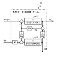
- FIG. 12 shows a block diagram of a first servo control unit for comparison.
- Position control block 50 of servo control unit 23 receives a fourth value obtained by adding position command ⁇ c and deflection correction value ⁇ sco (also referred to as position command correction value ⁇ sco) output from deflection correction block 24.
- the fifth value is obtained by subtracting the motor rotational position ⁇ M from the fourth value.
- the fifth value is multiplied by the position proportional gain Kpp to generate the speed command ⁇ c.
- the motor rotational position ⁇ M is obtained from the detection signal of the first encoder 14 which is a position detector.
- the motor rotational position ⁇ M is differentiated to obtain the motor speed ⁇ M.
- the motor speed ⁇ M is subtracted from the speed command ⁇ c to obtain a sixth value.
- the sixth value is multiplied by the speed proportional gain Kps to obtain a seventh value.
- the sixth value is integrated and multiplied by the velocity integral gain Ki to obtain an eighth value.
- the seventh value and the eighth value are added to calculate the current supplied to the first motor 12 to obtain the motor current command IM.
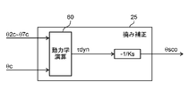
- FIG. 13 shows a detailed configuration of the deflection correction block shown in FIG.
- the deflection correction block 25 has a dynamics calculation block 60.
- (Equation 2) in order to obtain the position command correction value ⁇ sco, it is necessary to obtain the external force torque ⁇ ddyn in advance, but it is necessary to attach a torque sensor to each joint axis and obtain this from the aspect of cost Unfavorable to see. This is because torque sensors are generally expensive. Also, by attaching a torque sensor to each joint shaft, an extra deflection is added to the robot arm 2.
- the dynamics calculation block 60 obtains the external force torque calculation value ⁇ dyn.
- the dynamics operation block 60 performs a dynamics operation using the position commands ⁇ c to ⁇ 7c of all the axes, the velocity components which are their differential values, and the acceleration components which are their second order differential values, and The external force torque is calculated.
- the external-command torque calculated value ⁇ dyn is multiplied by the reciprocal of the spring constant Ks and the sign-reversed sign to obtain a position command correction value ⁇ sco.
- the external force torque calculation value ⁇ dyn includes both the gravitational torque ⁇ g and the interference torque ⁇ a. Therefore, the actual correction amplitude of the deflection due to the high frequency interference torque ⁇ a decreases.
- the position command correction value ⁇ sco is increased, the position command correction value by the gravity torque ⁇ g is also increased. As described above, this causes the problem that the arm is pulled up more than the amount of deflection due to gravity and sinking.
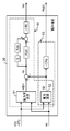
- FIG. 14 shows a block diagram of a first servo control unit according to the present embodiment, and in this first servo control unit 23, the functional blocks excluding the deflection correction block 24 are the same as the configuration shown in FIG. So I will omit the explanation.
- FIG. 15 shows a detailed configuration of the deflection correction block 24 shown in FIG.
- the deflection correction block 24 (deflection correction means) has a dynamics calculation block 61 and a gravity calculation block 62.
- the dynamics operation block 61 obtains an external force torque operation value ⁇ dyn using position commands ⁇ c to ⁇ 7c sent from the main control unit 22 for all axes.
- the calculation of the external force torque applied to each joint axis in the dynamics calculation block 61 is the same as the above-described method illustrated for comparison. That is, when the number of joint axes is n (n is an integer of 2 or more), one deflection correction block 24 corresponds to n servomotors 12, 12 ... sent from the main control unit 22. The n position commands ⁇ c to ⁇ nc are received, and based on these position commands, the positional deviation of the robot arm 2 due to the deflection of the reduction gear 13 is corrected.
- the gravity torque ⁇ g and the interference torque ⁇ a are separated in the deflection correction block 24, and the position command correction value for each is calculated.
- the gravity calculation block 62 receives the position commands ⁇ c to ⁇ 7c in the same manner as the dynamics calculation block 61.
- the gravity calculation block 62 calculates the gravity torque ⁇ g by performing the dynamics calculation with the above-mentioned velocity component and acceleration component as zero.
- any of the external force torque calculation value ⁇ dyn, the gravity torque ⁇ g, and the interference torque ⁇ a can be obtained by calculation in the deflection correction block 24.
- the first position command correction value ⁇ sgc is obtained from (Expression 9) using the obtained gravity torque ⁇ g.
- Kpa a PD compensation proportional gain, which is a coefficient for amplitude compensation.
- Kda a PD compensation differential gain, which is a coefficient for phase compensation.
- s is an integral element.
- the position command correction value ⁇ sc is obtained from the values calculated by (Equation 9) and (Equation 11).
- the gravity calculation block 62 and the calculation function shown in Equation 9 in the deflection correction block 24 will be collectively referred to as a first position command correction value calculation means 63. Also, the second position command correction value calculation is performed by combining the calculation functions shown in (Equation 8), (Equation 10) and (Equation 11) in the dynamics calculation block 61, the gravity calculation block 62, and the deflection correction block 24. It will be called means 64.
- a new position command ( ⁇ c + ⁇ sc) in which the position command correction value ⁇ sc represented by (Expression 12) is added to the position command ⁇ c sent from the main control unit 22 to the first servo control unit 23 is The first servo control unit 23 is input.
- the first servo control unit 23 controls the drive of the first motor 12 by a new position command.
- FIG. 16A and 16B show the response characteristic of the transfer function to the operating frequency of the main shaft according to this embodiment
- FIG. 16A shows the frequency response characteristic of the amplitude of the transfer function WcL
- FIG. 16B shows the frequency response characteristic of the phase of the transfer function WcL.
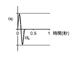
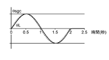
- FIG. 16C shows the time of the first position command correction value ⁇ sgc and the actual position ⁇ L when a sine wave of 0.5 Hz is given as the first position command correction value ⁇ sgc to the main axis having the frequency characteristics shown in FIGS. 16A and 16B.
- FIG. 16D shows waveforms
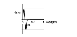
- FIG. 16D shows time waveforms of the second position command correction value ⁇ skc and the actual position ⁇ L when a 5 Hz sine wave is given as the second position command correction value ⁇ skc.
- the actual position ⁇ L sufficiently follows the first position command correction value ⁇ sgc.
- the frequency of the first position command correction value ⁇ sgc is 0.5 Hz which is the maximum value of the vibration frequency of the robot arm 2 due to the gravity torque ⁇ g.
- the actual position ⁇ L sufficiently follows both the amplitude and the phase with respect to the second position command correction value ⁇ skc having a frequency of 5 Hz.
- the gravity torque ⁇ g and the interference torque ⁇ a are separately calculated and calculated.
- First and second position command correction values ⁇ sgc and ⁇ skc are obtained based on the torque. By this, it is possible to correct the position command without excessively estimating the influence of the deflection due to the gravity torque ⁇ g. Also, by adding these position command correction values ⁇ sgc and ⁇ skc to the original position command ⁇ c, it is possible to correct the positional deviation of the robot arm 2 with high accuracy.
- each deflection correction block 24 receives seven position commands ⁇ c to ⁇ 7c sent from the main control unit 22 to the seven servo control units 23, 23.
- the individual deflection correction block 24 calculates the external force torque operation value ⁇ dyn and the gravity torque ⁇ g by kinetic operation based on these position commands ⁇ c to ⁇ 7c. Therefore, it is not necessary to provide a dedicated part for measuring torque, such as a torque sensor, and the cost of the vertical articulated six-axis robot 6 and the robot control device 20 can be reduced.
- the interference torque ⁇ a is obtained by subtracting the gravity torque ⁇ g from the external force torque calculation value ⁇ dyn. Therefore, the gravitational torque ⁇ g and the interference torque ⁇ a can be easily separated, and the positional deviation of the robot arm 2 due to the bending can be corrected.
- position teaching of a robot is increasingly performed off-line using a GUI such as a personal computer instead of teaching playback.
- teaching / playback there is no problem as long as the repeat accuracy is high even if the tip position of the robot arm 2 instructed to the motors 12, 12... And the tip position of the actual robot arm 2 deviate.
- the off-line teaching requires an absolute position accuracy, if the above-mentioned deflection correction is not correctly performed, it becomes a problem in controlling the robot.
- the positional deviation of the robot arm 2 due to the bending can be accurately corrected, and off-line teaching can be smoothly performed.
- FIG. 17 is a block diagram of a first servo control unit according to the present embodiment.
- the difference between the configuration shown in the present embodiment and the configuration shown in the first embodiment is the following three points.
- One is to obtain an interference torque current compensation value Isc (hereinafter simply referred to as a current compensation value) in the deflection correction block 26 based on the interference torque ⁇ a.
- the second is to add the current compensation value Isc to the motor current command IM.
- the third is that only the first position command correction value ⁇ sgc is added to the position command ⁇ c.
- FIG. 18 shows a detailed configuration of the deflection correction block shown in FIG.
- the gravity torque ⁇ g is calculated by the gravity calculation block 62, and the interference torque ⁇ a is calculated by (Expression 7), as in the first embodiment.
- the position command correction value ⁇ sc shown in (Expression 12) is corrected as shown in (Expression 13).
- the deflection correction value ⁇ sac ⁇ sgc (Equation 13)
- the deflection correction value ⁇ sac is not determined from the interference torque ⁇ a, but a current corresponding to the deflection correction value ⁇ sac is determined.
- the compensation of the amplitude and the phase is also required for the current, and the current compensation value Isc is represented by the following (Expression 14).
- Kpb is an interference torque current compensation proportional gain, which is a coefficient for amplitude compensation.
- Kdb is an interference torque current compensation differential gain and is a coefficient for phase compensation.
- Other calculation elements are as described above.
- the motor current command IMb output from the speed control block 52 is represented by the following (Equation 15) based on the value calculated by (Equation 14).
- the new position command is input to the position control block 50 of the first servo control unit 23.
- the current compensation value Isc is added to the motor current command IM generated in the position control block 50 and the speed control block 51 to obtain a new motor current command IMb.
- the drive of the first motor 12 is controlled based on the new position command ( ⁇ c + ⁇ sgc) and the new motor current command IMb.
- the deflection of the motor current is corrected directly based on the interference torque ⁇ a by adding the current compensation value Isc due to the interference torque ⁇ a to the motor current command IM.
- the response of the load 30 can be enhanced. That is, the correction effect of the deflection due to the interference torque ⁇ a can be improved.
- deflection due to the interference torque ⁇ a is generated within the position control block 50 and the speed control block 52 instead of the position commands ⁇ c to ⁇ 7c sent from the outside of the position control block 50 or the speed control block 52.
- the correction is added to the motor current command IM. That is, since the deflection is indirectly compensated, the whole of the current compensation value Isc added to the motor current command IM does not necessarily contribute to the decrease in deflection. Therefore, in order to accurately determine the current compensation value Isc, it may be necessary to repeat the operation check on the actual device and the adjustment of the gain and the like.
- the vertical articulated seven-axis robot 6 has been described as an example, but the present invention is not particularly limited thereto.
- the number of joint axes of the robot is not limited to seven, and may be appropriately changed according to the specification of the robot.
- the robot controller 20 has n (n is an integer of 2 or more) servo controllers 23, 23... Corresponding n servo motors 12, 12. While driving, n joint shafts are driven via reduction gears 13, 13... Respectively connected to n servo motors 12, 12.
- the deflection correction blocks 24 and 26 receive n position commands ⁇ c to ⁇ nc sent from the main control unit 22 to the n servo control units 23, 23. It is comprised so that the position shift of the robot arm 2 by bending may be correct
- the robot control device can separate the deflection due to the gravity torque and the deflection due to the interference torque from the other axes, and correct the position command for each, so that the positional deviation of the robot arm can be reduced. It is useful when applied to industrial robots such as welding robots.
Abstract
ロボット制御装置は、メイン制御部と、位置指令θcをメイン制御部から受け取るサーボ制御部と、サーボモータに連結された減速機の撓みを補正する撓み補正ブロック(24)とを備えている。撓み補正ブロック(24)は、位置指令θcに基づいて第1位置指令補正値θsgcを求める第1位置補正値演算手段(63)と、干渉トルクτaに基づいて第2位置指令補正値θskcを求める第2位置指令補正値演算手段(64)と、を有している。サーボ制御部は、第1位置指令補正値θsgcと第2位置指令補正値θskcとを位置指令θcに加算した新たな位置指令に基づきサーボモータを駆動する。
Description
本開示はロボット制御装置に関し、特に、減速機の撓みによるロボットアームの位置ずれ等を補正するロボットの制御に関する。
近年、溶接や切断等の加工において、タクト短縮や仕上げの精度の観点から、レーザ加工を行う需要が高まってきている。この場合、レーザ加工の高速性、高精度を発揮させるために、多関節ロボットのロボットアームの先端にレーザ出力装置を装着して加工を行うことが多い。
通常の多関節ロボットは、サーボモータを駆動して関節軸を回転させることで、ロボットアームを動作させている。サーボモータの駆動力は、サーボモータに連結された減速機を介して関節軸に伝達される。このような多関節ロボットでは、サーボモータに指令したロボットアーム先端位置と、実際のロボットアーム先端位置とが減速機のバネ成分によってずれてしまう、いわゆる撓みという現象が発生していた。たとえば、ロボットアームが重力による力(以下、重力トルクという)を受けている場合や、ロボットアームが有する一の関節軸が、他の関節軸から干渉による力(以下、干渉トルクという)を受けている場合に撓みは発生する。
そこで、撓み量に基づく補正値を演算により求め、位置指令に補正値を加算するという撓み補正が提案されている(例えば、特許文献1参照)。具体的には、各関節軸の減速機にかかる外力トルクを演算し、減速機のバネ定数で除算して撓み量を求める。この撓み量は、撓みによって生じるロボットアームの先端位置のずれ量、あるいは関節軸の角度のずれ量に相当する。撓み量に基づく補正値は位置指令に逆向きに加算される。
多関節ロボットにおいて、減速機に発生する撓みの挙動は、重力トルクに起因する成分と干渉トルクに起因する成分とでそれぞれ異なる。したがって、上記の従来技術のように重力トルクと干渉トルクが合算された外力トルクから直接に補正を行った場合、撓み補正が正しく行われないおそれがある。
本開示はかかる点に鑑みてなされたもので、その目的は、減速機の撓みの影響を低減し、精度良くロボットアームの位置ずれを補正可能なロボット制御装置を提供することにある。
上記目的を達成するために、本開示の一態様に係るロボット制御装置は、各関節軸に連結された減速機にかかる重力トルクと干渉トルクとを個別に求める。得られた重力トルクと干渉トルクとにそれぞれ基づいて撓み補正値が求められる。これらの値を用いてモータに与えられる位置指令が補正される。
具体的には、本開示の一態様に係るロボット制御装置は、サーボモータに連結された減速機を介して駆動される関節軸を有するロボットアームの運動制御を行うロボット制御装置であって、位置指令を送信するメイン制御部と、サーボ制御部と、減速機の撓みによるロボットアームの位置ずれを補正するための撓み補正手段と、を備え、撓み補正手段は、減速機の撓みを発生させる外力トルクのうち重力トルクを位置指令に基づいて演算し、重力トルクに基づいて第1位置指令補正値を求める第1位置指令補正値演算手段と、位置指令と重力トルクとに基づいて外力トルクのうち関節軸が受ける干渉によって発生する干渉トルクを演算し、干渉トルクに基づいて第2位置指令補正値を求める第2位置指令補正値演算手段と、を有し、サーボ制御部は、第1位置指令補正値と第2位置指令補正値とを位置指令に加算して得られる新たな位置指令に基づいてサーボモータを駆動することを特徴とする。
この構成によれば、撓みに与える重力トルクの影響と干渉トルクの影響とを分離し、それぞれに対して位置指令補正値を求めることができるため、ロボットアームの位置ずれを精度良く補正することができる。
第2位置指令補正値は、干渉トルクに基づいて得られた撓み補正値の振幅及び位相がそれぞれ補償された値であるのが好ましい。
この構成によれば、干渉トルクによる撓みの影響を確実に補正することができる。
本開示の別の態様に係るロボット制御装置は、サーボモータに連結された減速機を介して駆動される関節軸を有するロボットアームの運動制御を行うロボット制御装置であって、位置指令を送信するメイン制御部と、サーボ制御部と、減速機の撓みによるロボットアームの位置ずれを補正するための撓み補正手段を備え、撓み補正手段は、位置指令に基づいてロボットアームの撓みを発生させる外力トルクのうち重力トルクを演算し、重力トルクに基づいて第1位置指令補正値を求める第1位置指令補正値演算手段と、位置指令と重力トルクに基づいて外力トルクのうち関節軸が受ける干渉によって発生する干渉トルクを演算し、干渉トルクに基づいて電流補償値を求める電流補償値演算手段と、サーボ制御部は、第1位置指令補正値を位置指令に加算して得られる新たな位置指令と、を有し、新たな位置指令に基づいて生成されたモータ電流指令に電流補償値を加算して得られる新たなモータ電流指令とに基づいてサーボモータを駆動することを特徴とする。
この構成によれば、撓みに与える重力トルクの影響と干渉トルクの影響とを分離し、特に干渉トルクに関してはモータ電流に対する補償値を求めて撓み補正を行うことができる。このことにより、ロボットアームの位置ずれを応答性良く補正することができる。
電流補償値は、干渉トルクに基づいて得られた撓み補正値の振幅及び位相がそれぞれ補償された値に所定の係数を乗じた値であるのが好ましい。
この構成によれば、干渉トルクによる撓みの影響を確実に補正することができる。
サーボモータは、n(nは2以上の整数)個のサーボモータのうちの一つであり、減速機は、n個のサーボモータにそれぞれ連結されたn個の減速機のうちの一つであり、関節軸は、n個の減速機を介してそれぞれ駆動されるn個の関節軸のうちの一つであり、サーボ制御部は、n個のサーボモータをそれぞれ駆動するn個のサーボ制御部のうちの一つであり、位置指令は、n個の関節軸のそれぞれの位置を指定するn個の位置指令のうちの一つであり、撓み補正手段は、n個のサーボ制御部にそれぞれ対応するn個の撓み補正手段のうちの一つであり、位置指令に加えて、n個の位置指令のうちの残りのn-1個の位置指令に基づいて、撓みによるロボットアームの位置ずれを補正するように構成されているのが好ましい。
この構成によれば、各関節軸に連結されたサーボモータの位置指令を用いて撓み補正を行うため、トルクセンサ等の専用部品を設けずに済み、コストを低減できる。
外力トルク及び重力トルクはそれぞれ動力学演算によって得られ、干渉トルクは、外力トルクから重力トルクを減算して得られるのが好ましい。
この構成によれば、重力トルクと干渉トルクとを簡便に分離することができ、撓みによるロボットアームの位置ずれを補正することができる。
以上説明したように、本開示によれば、重力トルクに起因する撓みと他軸からの干渉トルクに起因する撓みを分離して、精度良くロボットアームの位置ずれを補正できる。
以下、本開示の実施形態を図面に基づいて詳細に説明する。以下の好ましい実施形態の説明は、本質的に例示に過ぎず、本開示、その適用物或いはその用途を制限することを意図するものでは全くない。
(本開示の基礎となった知見)
上述のように、減速機のバネ成分に起因してロボットアームに撓みが生じる。撓みを補正するにあたって、減速機に加わる外力トルクを考慮することが好ましい。外力トルクは、重力によるトルクと他の関節軸から受ける干渉トルクとを含む。本願発明者等は、重力トルクと干渉トルクとで、撓み補正後の位置指令に与える影響、具体的には応答周波数が異なることを見いだした。以下、垂直多関節ロボットの動作を例にとって説明する。
上述のように、減速機のバネ成分に起因してロボットアームに撓みが生じる。撓みを補正するにあたって、減速機に加わる外力トルクを考慮することが好ましい。外力トルクは、重力によるトルクと他の関節軸から受ける干渉トルクとを含む。本願発明者等は、重力トルクと干渉トルクとで、撓み補正後の位置指令に与える影響、具体的には応答周波数が異なることを見いだした。以下、垂直多関節ロボットの動作を例にとって説明する。
[垂直多関節ロボットの構成及び動作]
図1は、レーザ溶接や切断で用いられる従来の垂直多関節ロボットの構成を示す。この垂直多関節6軸ロボット1は、ロボットアーム2と関節軸J1~J6とを有している。ロボットアーム2は複数の部分に分かれており、各部分の連結部に関節軸J1~J6をそれぞれ備えている。また、関節軸J1~J6はそれぞれ減速機(図示せず)を介してサーボモータ(図示せず)を連結している。ロボット制御装置20は、位置指令θc(図10参照)により、各サーボモータを駆動して関節軸J1~J6をそれぞれ所望の量だけ回転させてロボットアーム2の動作及び姿勢を制御する。ロボットアーム2の先端にはレーザ出力装置3が装着されている。レーザ出力装置3にはレーザ光4を発生させるレーザ光源(図示せず)と、レーザ光4を導波する光ファイバ(図示せず)とが接続されている。
図1は、レーザ溶接や切断で用いられる従来の垂直多関節ロボットの構成を示す。この垂直多関節6軸ロボット1は、ロボットアーム2と関節軸J1~J6とを有している。ロボットアーム2は複数の部分に分かれており、各部分の連結部に関節軸J1~J6をそれぞれ備えている。また、関節軸J1~J6はそれぞれ減速機(図示せず)を介してサーボモータ(図示せず)を連結している。ロボット制御装置20は、位置指令θc(図10参照)により、各サーボモータを駆動して関節軸J1~J6をそれぞれ所望の量だけ回転させてロボットアーム2の動作及び姿勢を制御する。ロボットアーム2の先端にはレーザ出力装置3が装着されている。レーザ出力装置3にはレーザ光4を発生させるレーザ光源(図示せず)と、レーザ光4を導波する光ファイバ(図示せず)とが接続されている。
以降では、垂直多関節6軸ロボット1が、全体の姿勢を決める主軸3軸J1~J3と先端の方向を決める手首3軸J4~J6の合計6つの関節軸を有する構成であるとして、その動作を説明する。なお、図1に示すX,Y,Z方向を垂直多関節6軸ロボット1の位置や移動を説明するために用いることがある。
レーザ出力装置3からレーザ光4を照射してワーク5を切断する作業を考える。レーザ出力装置3は例えば、5kg程度の質量である。レーザ光4の照射位置及び方向を定めると6軸を有する垂直多関節6軸ロボット1ではロボットアーム2の姿勢、つまり、各関節軸の角度は一意に決まる。このように、関節軸の制御冗長性はゼロなので、円軌跡で切断を行うと全関節軸が動作することになる。
例えば、直径10mmの円を10m/分で切断する作業を仮定すると、動作時間は約0.2秒で動作周波数は約5Hzとなる。各関節軸は動作周波数に対応した正弦波状の位置指令θcを受け取り動作する。ここで位置指令θcに対して実際の各関節軸が応答動作できる周波数を位置応答周波数と定義し、実際の各関節軸の位置(以下、実位置という)をθLとする。なお、位置指令θcは各関節軸の回転角度量を指示する角度指令を示し、実位置θLは、実際に各関節軸が回転した回転角度量を示す。位置応答周波数は、垂直多関節6軸ロボット1を構成する各関節軸の固有振動周波数や、各関節軸を駆動する制御装置(図9参照)の特性で決まる。位置指令θcを受けて各関節軸が実位置θLに到達するまでの伝達関数WcLを以下の(式1)で定義する。
WcL = θL/θc ・・・(式1)
なお、以降の説明では、位置応答周波数は、伝達関数WcLの振幅が半分(-6dB)となる周波数、あるいは伝達関数WcLの位相が90°遅れた周波数のいずれか低い方とする。
なお、以降の説明では、位置応答周波数は、伝達関数WcLの振幅が半分(-6dB)となる周波数、あるいは伝達関数WcLの位相が90°遅れた周波数のいずれか低い方とする。
主軸3軸J1~J3は物理的に大きく、重いので位置応答周波数を高めることは難しい。例えばアーム長2m、可搬質量10kg程度のロボットにおいて、位置応答周波数はアーム伸張姿勢(イナーシャが最大)で最小となり、5Hz程度となる。
図2A,2Bは、主軸の動作周波数に対する伝達関数の応答特性を示し、図2Aは上記の伝達関数WcLの振幅の周波数応答特性を、図2Bは伝達関数WcLの位相の周波数応答特性をそれぞれ示している。また、図2Cは、図2A,2Bに示す周波数特性を有する主軸に対し、位置指令θcとして5Hzの正弦波を与えた場合のθcとθLの時間波形を示す。
図2A,2Bに示すように、位置応答周波数が5Hzの場合、振幅が半分(-6dB)になり、位相が90°遅れている。また、図2Cに示すように位置指令θcに対し実位置θLの振幅が半分になり、位相が90°遅れている。
つまり、直径10mmの円を10m/分でレーザ切断する作業において、位置応答周波数5Hzの主軸を動作させると、ロボットアーム2の先端が描く円軌跡の直径が半減し、形状が歪む等、満足な軌跡が得られないことになる。
一方、手首3軸J4~J6は主軸3軸J1~J3に比べ小さく軽い。そのため、5kg程度のレーザ出力装置3を装着していても、手首3軸J4~J6は10Hz以上の位置応答周波数をもつ。よって、ロボットアーム2の先端に新たな関節軸J7を追加してもよい。主軸3軸J1~J3は停止状態を維持し、手首3軸J4~J6と新たな関節軸J7とで位置決めや軌跡追従動作を実施することで、5Hz以上の動作周波数でもロボットアーム2は十分な位置応答性を実現できる。つまり、関節軸J6の回転中心位置8が動かないように、関節軸J1~J5を完全に静止させている。
図3は、先端の関節軸J6と平行な関節軸J7を追加した垂直多関節7軸ロボットの構成を示す。この垂直多関節7軸ロボット6は、先端部分の関節軸J6及びJ7のみを動作させて、ロボットアーム2の先端で円や楕円等の所望の軌道を描くことができる。
図4は、図3に示す垂直多関節7軸ロボット6のロボットアーム先端の軌跡の時間変化を示す。
時刻t1で、ロボットアーム2の関節軸J1~J5を駆動して、レーザ照射位置7を目標の円軌道の中心に移動させ、レーザ照射を開始する。時刻t2で、レーザ照射位置7を+Y方向へ動かして円軌道に乗せる様に関節軸J6,J7をそれぞれの回転方向9,10に回転させる。時刻t3~t5において、円軌道に沿ってレーザ照射位置7が移動するように関節軸J6,J7を回転させ、時刻t6でレーザ照射を終了する。
図5A,5Bは、ロボットアーム先端の動作周波数に対する伝達関数の応答特性を示し、図5Aは上記の伝達関数WcLの振幅の周波数応答特性を、図5Bは伝達関数WcLの位相の周波数応答特性をそれぞれ示している。なお、図5A,5Bにおいてロボットアーム先端とは関節軸J6,J7を指す。また、図5Cは、図5A,5Bに示す周波数特性を有するロボットアームに対し、位置指令θcとして5Hzの正弦波を与えた場合のθcとθLの時間波形を示す。前述したように、関節軸J6,J7は小さく軽いので、位置応答周波数は主軸と比べて高くなり、例えば20Hz程度となる。
よって、図5A,5Bに示すように、位置応答周波数が20Hzの場合、振幅が半分(-6dB)になり、位相が90°遅れる。図5Cに示すように、位置指令θcの周波数が5hzの場合は、実位置θLは振幅の減衰や位相の遅れが少なく、図2Cに示した場合に比べ、実位置θLが位置指令θcによく追従していることがわかる。
この場合は、直径10mmの円を10m/分でレーザ切断する作業において、図4に示すように、ほぼ指令通りにロボットアーム2の先端は円軌跡を描くことができる。
[ロボットアームの関節軸の動作に伴う干渉トルクの発生及びその影響]
しかし、関節軸J6,J7が動作することで関節軸J1~J5に対して干渉トルクを発生させ、それぞれの関節軸に連結した減速機に撓みが生じる。特に主軸3軸J1~J3の回転位置はロボットアーム2の先端までの距離が長い。本願発明者等は、これらの関節軸に連結した減速機が少しでも撓むと関節軸J6の回転中心位置8が大きく揺動し、ロボットアーム2の先端が描く軌跡に大きく影響を与えることを見いだした。
しかし、関節軸J6,J7が動作することで関節軸J1~J5に対して干渉トルクを発生させ、それぞれの関節軸に連結した減速機に撓みが生じる。特に主軸3軸J1~J3の回転位置はロボットアーム2の先端までの距離が長い。本願発明者等は、これらの関節軸に連結した減速機が少しでも撓むと関節軸J6の回転中心位置8が大きく揺動し、ロボットアーム2の先端が描く軌跡に大きく影響を与えることを見いだした。
本願発明者等は、直径10mmの円を10m/分でレーザ切断する作業において、実際に関節軸J6の回転中心位置8の揺動を調査した。この調査により、関節軸J6に1mm程度の揺れが生じており、ロボットアーム2の先端が描く軌跡に10%程度の誤差を与えてしまうことがわかった。また、図3に示す垂直多関節7軸ロボット6では、関節軸毎に減速機の特性も異なる。そのため、それぞれの減速機で発生する撓み量も異なり、関節軸J6の回転中心位置8の揺れ方もいびつになる。
図6は、減速機に撓みが生じた場合の垂直多関節7軸ロボット6のロボットアーム先端の軌跡の時間変化を示す。
時刻t1で、ロボットアーム2の関節軸J1~J5を駆動して、レーザ照射位置7を目標の円軌道の中心に移動させ、レーザ照射を開始する。図4の例と同様に、時刻t2でレーザ照射位置7を+Y方向へ動かして、ロボットアーム2の先端を円軌道に乗せるように関節軸J6,J7を回転させる。しかし、関節軸J6,J7の動作によって生じる干渉トルクにより、主に関節軸J1の減速機が撓み、関節軸J6の回転中心位置8が+Y方向へずれる。時刻t3では円軌道に沿って+X方向へレーザ照射位置7を移動させるので、その干渉トルクで主に関節軸J2の減速機が撓み、関節軸J6の回転中心位置8が+X方向へずれる。ただし、関節軸J1,J2にそれぞれ連結された減速機の撓み量の違いにより、関節軸J6の回転中心位置8の+X方向へのずれ量は+Y方向のずれ量に対して半分程度になる。以下、時刻t3~t5においても、干渉トルクの影響で関節軸J6の回転中心位置8の位置ずれが発生する。このため、位置指令θcが円軌跡なのに対し、実位置θLの軌跡はその円軌跡よりも少し膨らんだ楕円軌跡になってしまう。
6軸構成で主軸3軸J1~J3を動作させた場合、例えば、円軌跡の直径が50%程度減少する誤差が発生することがある。この誤差に比べれば上記の実位置θLの軌跡の誤差は小さいが、一般にロボットを使用して加工を行う場合の許容誤差を超えているため、何らかの対策を行う必要がある。
図7は、外力トルクによって発生するロボットアーム先端の位置ずれを説明する模式図を示す。主軸3軸J1~J3に加わる外力トルクτddyn1,τddyn2,τddyn3は、それぞれ重力トルクと干渉トルクとの和、すなわち、(τg1+τa1),(τg2+τa2),(τg3+τa3)になる。なお、説明の便宜上、図7には関節軸J2の撓み量θs2のみを示している。
この場合、位置指令θcに加算する撓み補正値θsc(以下、位置指令補正値という)は減速機のバネ定数をKsとすると以下の(式2)で表わされる。
θsc = -θs = -τddyn/Ks ・・・(式2)
ここで、θsは、後述する減速機の1次側と2次側との間に発生する撓み量である。
ここで、θsは、後述する減速機の1次側と2次側との間に発生する撓み量である。
また、重力トルクτgによる撓み補正値θsgc(以下、第1位置指令補正値という)と干渉トルクτaによる撓み補正値θsacとは以下の(式3)、(式4)でそれぞれ表わされる。
θsgc = -τg/Ks ・・・(式3)
θsac = -τa/Ks ・・・(式4)
従って、全体の位置指令補正値θscは以下のようになる。
θsac = -τa/Ks ・・・(式4)
従って、全体の位置指令補正値θscは以下のようになる。
θsc = -(τg+τa)/Ks = θsgc+θsac ・・・(式5)
ここで、(式5)で表わされる位置指令補正値θscを位置指令θcに加算して撓み補正を実行すると、重力トルクτgによる第1位置指令補正値θsgcは十分に補正される。その理由は以下の通りである。
ここで、(式5)で表わされる位置指令補正値θscを位置指令θcに加算して撓み補正を実行すると、重力トルクτgによる第1位置指令補正値θsgcは十分に補正される。その理由は以下の通りである。
主軸3軸J1~J3が停止している間は、重力トルクτgの周波数は0Hzである。また、アーム長2m、可搬質量10kg程度のロボットの主軸3軸J1~J3は、動作角速度が180°/秒程度であり、1秒間で半周程度しか回転しないので、主軸3軸J1~J3が動作中でも重力トルクτgの変化は0.5Hz未満である。よって、重力トルクτgによるロボットアーム2の振動周波数も0.5Hz未満となる。主軸3軸J1~J3の位置応答周波数が5Hz程度であっても、十分に追従でき、撓み補正が可能となる。
一方、干渉トルクτaによる撓みは、位置指令θcに干渉トルクτaによる撓み補正値θsacを加算しても十分に補正されない。その理由は以下の通りである。
前述の切断動作(直径10mmの円を10m/分で切断)において、干渉トルクτaによるロボットアーム2の撓みの中心周波数は5Hzとなる。よって、(式4)に示すように、干渉トルクτaによる撓み補正値θsacの周波数も5Hzとなる。
図8A,8Bは、減速機に撓みが生じた場合の主軸の動作周波数に対する伝達関数の応答特性を示し、図8Aは上記の伝達関数WcLの振幅の周波数応答特性を、図8Bは伝達関数WcLの位相の周波数応答特性をそれぞれ示している。図8Cは、図2A,2Bに示す周波数特性を有する主軸に対し、位置指令θcとして0.5Hzの正弦波を与えた場合のθcとθLの時間波形を示し、図8Dは、位置指令θcとして5Hzの正弦波を与えた場合のθcとθLの時間波形を示す。
図8Cに示すように、第1位置指令補正値θsgcに対しては、実位置θLは十分に追従している。なお、第1位置指令補正値θsgcの周波数は0.5Hzとしている。一方、図8Dに示すように、干渉トルクτaによる撓み補正値θsacに対しては、実位置θLは振幅が半分になり、位相が90°遅れているのがわかる。
以上説明したように、従来の方法では、重力トルクと干渉トルクに分離せず、外力トルクτddynを一体として計算し、この値に基づいて位置指令補正値θscを求めていた。よって、例えば、干渉トルクτaによる撓みの実際の補正振幅が小さくなることに対応して、位置指令補正値θscを増加させると、重力トルクτgによる第1位置指令補正値θsgcも併せて増加させてしまい、重力で撓んで沈んだ分以上にアームを引き上げてしまう不具合が発生する。
そこで、本願発明者等は、外力トルクを重力トルクと干渉トルクとに分離して求め、これらの結果に基づいてロボットアーム2の位置ずれを補正することでロボットアーム2を所望の軌跡で動作できることを見いだした。このことについて以下に詳述する。
(実施形態1)
[多関節ロボット及びその制御系の構成]
図9は、図3に示す垂直多関節7軸ロボット6の位置制御に関する機能ブロック図であり、ロボットメカとロボット制御装置の内部構成の概略を示す。ロボットメカ11は、垂直多関節7軸ロボット6の機械的駆動部であり、サーボモータ12,12・・・(以下、単にモータという)と減速機13,13・・・とエンコーダ14,14・・・とを有している。また、図示しないがロボットメカ11は、ロボットアーム2を含んでいる。モータ12は減速機13を介して図3に示す垂直多関節7軸ロボット6の関節軸J1~J7にそれぞれ連結されている。モータ12は、ロボット制御装置20のサーボ制御部23から送られる制御信号により関節軸J1~J7を駆動し、ロボットアーム2の動作及ぶ姿勢を制御する。エンコーダ14は、モータ12に接続され、その回転量や回転速度を検出して、検出信号をフィードバック信号としてサーボ制御部23に送る。
なお、以降の説明において、関節軸J1に連結されたモータ12と減速機13とエンコーダ14とを、それぞれ「第1のモータ」、「第1の減速機」、「第1のエンコーダ」と呼ぶことがあり、関節軸J2~J7に連結されたモータ等を「第2~第7のモータ」等と呼ぶことがある。また、第1のモータに接続されたサーボ制御部23と撓み補正ブロック24とを、それぞれ「第1のサーボ制御部」、「第1の撓み補正ブロック」と呼ぶことがあり、第2~第7のモータに接続されたサーボ制御部と23,23・・・と第2~第7のサーボ制御部に接続された撓み補正ブロック24,24・・・とを、それぞれ「第2~第7のサーボ制御部」、「第2~第5の撓み補正ブロック」と呼ぶことがある。また、各関節軸に送られる位置指令や位置指令補正値を位置指令θc~θ7cや位置指令補正値θsc~θ7scと呼ぶことがある。
ロボット制御装置20は、操作・教示部21とメイン制御部22とサーボ制御部23と撓み補正ブロック24(撓み補正手段)とを有している。操作・教示部21は、例えば、ティーチング時に取得されたロボットアーム2の軌跡及び、この軌跡を描くための各モータ12,12・・・の回転動作等を記憶する。
メイン制御部22は、操作・教示部21からの指示を受け、操作・教示部21に記憶されたロボットメカ11のロボットアーム2等の移動の軌跡に従い、垂直多関節7軸ロボット6の各関節軸J1~J7の位置指令θc~θ7cをそれぞれ出力する。
第1~第7のサーボ制御部23,23・・・は、メイン制御部22から送られた位置指令θc~θ7cに追従するように、ロボットメカ11内の第1~第7のモータ12,12・・・の回転動作をそれぞれ制御する。
撓み補正ブロック24,24・・・は、関節軸J1~J7に対応して、メイン制御部22と各サーボ制御部23,23・・・との間にそれぞれ設けられている。撓み補正ブロック24,24・・・は、メイン制御部22から受け取った位置指令θc~θ7cに基づいて、位置指令補正値θsc~θ7scを生成する。生成された位置指令補正値θsc~θ7scは対応する位置指令θc~θ7cに加算されて第1~第7のサーボ制御部23,23・・・にそれぞれ送られる。
なお、ロボット制御装置20内の各機能ブロックは、それぞれ独立の回路で構成されていてもよいし、一つの集積回路で構成されていてもよい。一部の機能ブロックの組み合わせを一つの集積回路で構成してもよい。また、メイン制御部22やサーボ制御部23や撓み補正ブロック24の機能は、ソフトウェアで記述されたプログラムをCPU等の集積回路上で実行して概ね実現される。
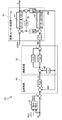
図10は、ロボットメカにおける減速機の撓みを説明する図を示す。図10に示すように、ロボットメカ11から、モータ12と減速機13とこれらに連結されるロボットアーム2の一部が負荷30として抽出されている。負荷30は、モータ取り付けベースとなる第1アーム31と、これに連結されたモータ12と、モータ12に連結された減速機1次側32とベアリング34を有する減速機2次側33とを含む減速機13と、減速機2次側33に回転可能に連結された第2アーム35とを含んでいる。
減速機1次側32はモータ12の回転軸を介してモータ12のロータ36に結合され、サーボ制御部23から送られたモータ回転位置θMの分だけ回転する。減速機13は、(式6)に示す減速比Rgで、モータ回転位置θMをアーム回転位置(実位置)θLに変換する。
Rg = θM/θL ・・・(式6)
しかし、図10に示すように、減速機13は減速機1次側32と減速機2次側33のと間にバネ成分37が存在するので、(式6)が成立するのは、バネの伸び、つまり撓みが一定となった定常状態のみである。
しかし、図10に示すように、減速機13は減速機1次側32と減速機2次側33のと間にバネ成分37が存在するので、(式6)が成立するのは、バネの伸び、つまり撓みが一定となった定常状態のみである。
図11は、図10に示す負荷のブロック線図を示し、IMはモータ12を駆動するモータ電流指令、Ktはモータ12のトルク定数、1/Rgは(式6)に示す減速比の逆数、Ksは減速機13のバネ定数、θsは減速機1次側32と減速機2次側33との間に発生する撓み量、τddynはロボットアーム2に加わる外力トルクである。なお、モータ12にはモータ電流指令IMで定められた電流が流れるものとする。
また、モータ伝達関数40において、JMはモータ12のロータ36と減速機1次側32とを合わせた回転軸回りの慣性モーメント、DMは粘性摩擦係数である。負荷伝達関数41において、JLは第2アーム35と減速機2次側33とを合わせた回転軸回りの慣性モーメント、DLは粘性摩擦係数である。
図11に示すように、モータ電流指令IMに基づいてモータ回転位置θMを得る。モータ回転位置θMに減速比の逆数1/Rgを乗じて第1の値を得る。一方、外力トルクτddynに基づいてアーム回転位置θLを得る。第1の値からアーム回転位置θLを差分して減速機1次側32と減速機2次側33との間に発生する撓み量θsを演算する。得られた撓み量θsにバネ定数Ksを乗じて第2の値を得る。第2の値は、外力トルクτddynに加算される。また、第2の値に減速比の逆数1/Rgを乗じて第3の値を得る。モータ電流指令IMとモータ12のトルク定数Ktとの積から第3の値が差分される。
なお、図11は、負荷及び減速機が連結されたモータの一般的な制御ブロック線図であるため、上記以外の機能の詳細説明は省略する。
[多関節ロボットの制御ブロックの詳細構成]
図12は、比較のための第1のサーボ制御部のブロック線図を示す。サーボ制御部23の位置制御ブロック50は、位置指令θcと撓み補正ブロック24から出力される撓み補正値θsco(位置指令補正値θscoともいう)とを加算した第4の値を受ける。第4の値からモータ回転位置θMを差分して第5の値を得る。第5の値に位置比例ゲインKppを乗じて速度指令ωcを生成する。モータ回転位置θMは位置検出器である第1のエンコーダ14での検出信号より得られる。なお、以降の説明において、第1のサーボ制御部23の構成等を例にとって説明するが、第2~第7のサーボ制御部23,23・・・)についても同様である。
図12は、比較のための第1のサーボ制御部のブロック線図を示す。サーボ制御部23の位置制御ブロック50は、位置指令θcと撓み補正ブロック24から出力される撓み補正値θsco(位置指令補正値θscoともいう)とを加算した第4の値を受ける。第4の値からモータ回転位置θMを差分して第5の値を得る。第5の値に位置比例ゲインKppを乗じて速度指令ωcを生成する。モータ回転位置θMは位置検出器である第1のエンコーダ14での検出信号より得られる。なお、以降の説明において、第1のサーボ制御部23の構成等を例にとって説明するが、第2~第7のサーボ制御部23,23・・・)についても同様である。
速度制御ブロック51において、モータ回転位置θMを微分してモータ速度ωMを得る。速度指令ωcからモータ速度ωMを差分して第6の値を得る。第6の値に速度比例ゲインKpsを乗じて第7の値を得る。また、第6の値を積分し、速度積分ゲインKiを乗じて第8の値を得る。第7の値と第8の値とを加算して第1のモータ12に流す電流を演算し、モータ電流指令IMを得る。
図13は、図12に示す撓み補正ブロックの詳細構成を示す。撓み補正ブロック25は、動力学演算ブロック60を有している。(式2)に示すように、位置指令補正値θscoを求めるには、外力トルクτddynを予め得ておく必要があるが、各関節軸にトルクセンサを取り付けてこれを求めるのはコストの面から見て好ましくない。トルクセンサは一般的に高価だからである。また、トルクセンサを各関節軸に取り付けることにより、ロボットアーム2に余分な撓みが付加されてしまう。
そこで全軸に対してメイン制御部22から送られた位置指令θc~θ7cを用い、動力学演算ブロック60で外力トルク演算値τdynを求める。動力学演算ブロック60では、全軸の位置指令θc~θ7c、それらの微分値である速度成分、及び、それらの2階微分値である加速度成分を用いて動力学演算を行い、各関節軸にかかる外力トルクを演算している。
この外力トルク演算値τdynにバネ定数Ksの負号反転した逆数を乗じて位置指令補正値θscoを求める。
θsco = τdyn×(-1/Ks) ・・・(式7)
ここで、前述したように、外力トルク演算値τdynは重力トルクτg、干渉トルクτaともに含んでいる。よって、周波数が高い干渉トルクτaによる撓みの実際の補正振幅が小さくなる。これに対応して、位置指令補正値θscoを増加させると、重力トルクτgによる位置指令補正値も併せて増加させてしまう。これにより重力で撓んで沈んだ分以上にアームを引き上げてしまう不具合が発生することは既に述べたとおりである。
ここで、前述したように、外力トルク演算値τdynは重力トルクτg、干渉トルクτaともに含んでいる。よって、周波数が高い干渉トルクτaによる撓みの実際の補正振幅が小さくなる。これに対応して、位置指令補正値θscoを増加させると、重力トルクτgによる位置指令補正値も併せて増加させてしまう。これにより重力で撓んで沈んだ分以上にアームを引き上げてしまう不具合が発生することは既に述べたとおりである。
図14は、本実施形態に係る第1のサーボ制御部のブロック線図を示し、この第1のサーボ制御部23において、撓み補正ブロック24を除く機能ブロックは図12に示す構成と同様であるので説明を省略する。図15は、図14に示す撓み補正ブロック24の詳細構成を示す。この撓み補正ブロック24(撓み補正手段)は、動力学演算ブロック61と重力演算ブロック62とを有している。動力学演算ブロック61は、全軸に対してメイン制御部22から送られた位置指令θc~θ7cを用いて外力トルク演算値τdynを求める。動力学演算ブロック61での各関節軸にかかる外力トルクの演算は比較のために例示した上記の手法と同様である。つまり、関節軸の数がn個(nは2以上の整数)である場合、一の撓み補正ブロック24は、メイン制御部22から送られるn個のサーボモータ12,12・・・に対応するn個の位置指令θc~θncを受け取り、これらの位置指令に基づいて、減速機13の撓みによるロボットアーム2の位置ずれを補正するように構成されている。
一方、本実施形態においては、撓み補正ブロック24で、重力トルクτgと干渉トルクτaとを分離し、それぞれに対する位置指令補正値を演算している。重力演算ブロック62は、動力学演算ブロック61と同様に位置指令θc~θ7cを受ける。この重力演算ブロック62は前述の速度成分及び加速度成分をゼロとして動力学演算を行うことにより重力トルクτgを求めている。
また、外力トルク演算値τdynから重力トルクτgを差分することにより、(式8)に示すように干渉トルクτaが得られる。
τa = τdyn-τg ・・・(式8)
以上に示すように本実施形態では、外力トルク演算値τdyn、重力トルクτg、干渉トルクτaのいずれも撓み補正ブロック24内での演算により求められる。
以上に示すように本実施形態では、外力トルク演算値τdyn、重力トルクτg、干渉トルクτaのいずれも撓み補正ブロック24内での演算により求められる。
また、得られた重力トルクτgを用いて、(式9)から第1位置指令補正値θsgcが得られる。
θsgc = τg×(-1/Ks) ・・・(式9)
一方、干渉トルクτaによる撓み補正値θsacは以下の式(式10)より演算される。
一方、干渉トルクτaによる撓み補正値θsacは以下の式(式10)より演算される。
θsac = τa×(-1/Ks) ・・・(式10)
なお、前述の通り、撓み補正値θsacの振幅と位相とには、実位置θLに対応するように補償、例えば、比例補償と位相進み補償とを行うPD補償を施す必要がある。これらを補償したθskc(以下、第2位置指令補正値という)を(式11)に示す。
なお、前述の通り、撓み補正値θsacの振幅と位相とには、実位置θLに対応するように補償、例えば、比例補償と位相進み補償とを行うPD補償を施す必要がある。これらを補償したθskc(以下、第2位置指令補正値という)を(式11)に示す。
θskc = Kpa×θsac+Kda×(s・θsac) ・・・(式11)
ここで、Kpaは、PD補償比例ゲインであり、振幅補償のための係数である。Kdaは、PD補償微分ゲインであり、位相補償のための係数である。また、sは積分要素である。
ここで、Kpaは、PD補償比例ゲインであり、振幅補償のための係数である。Kdaは、PD補償微分ゲインであり、位相補償のための係数である。また、sは積分要素である。
(式9),(式11)で算出した値から位置指令補正値θscが得られる。
θsc = θsgc+θskc ・・・(式12)
なお、重力演算ブロック62と撓み補正ブロック24内での(式9)に示す演算機能とを合わせて、第1位置指令補正値演算手段63と呼ぶこととする。また、動力学演算ブロック61と重力演算ブロック62と撓み補正ブロック24内での(式8),(式10),(式11)に示す演算機能とを合わせて、第2位置指令補正値演算手段64と呼ぶこととする。
なお、重力演算ブロック62と撓み補正ブロック24内での(式9)に示す演算機能とを合わせて、第1位置指令補正値演算手段63と呼ぶこととする。また、動力学演算ブロック61と重力演算ブロック62と撓み補正ブロック24内での(式8),(式10),(式11)に示す演算機能とを合わせて、第2位置指令補正値演算手段64と呼ぶこととする。
図14に示すように、メイン制御部22から第1のサーボ制御部23に送られる位置指令θcに(式12)で表わされる位置指令補正値θscが加算された新たな位置指令(θc+θsc)が第1のサーボ制御部23に入力される。第1のサーボ制御部23は、新たな位置指令によって第1のモータ12の駆動を制御する。
図16A,16Bは、本実施形態に係る主軸の動作周波数に対する伝達関数の応答特性を示し、図16Aは伝達関数WcLの振幅の周波数応答特性を、図16Bは伝達関数WcLの位相の周波数応答特性をそれぞれ示している。図16Cは、図16A,16Bに示す周波数特性を有する主軸に対し、第1位置指令補正値θsgcとして0.5Hzの正弦波を与えた場合の第1位置指令補正値θsgcと実位置θLの時間波形を示し、図16Dは、第2位置指令補正値θskcとして5Hzの正弦波を与えた場合の第2位置指令補正値θskcと実位置θLの時間波形を示す。
図16Cに示すように、第1位置指令補正値θsgcに対して実位置θLは十分に追従している。なお、第1位置指令補正値θsgcの周波数は、重力トルクτgによるロボットアーム2の振動周波数の最大値である0.5Hzとしている。一方、図16Dに示すように、5Hzの周波数を有する第2位置指令補正値θskcに対しても実位置θLは、振幅、位相とも十分追従している。
以上説明したように、本実施形態によれば、ロボットアーム2に加わる外力トルクτddynのうち動作応答周波数の異なる成分、つまり、重力トルクτgと干渉トルクτaとを分離してそれぞれ演算し、これらのトルクに基づいて第1及び第2位置指令補正値θsgc,θskcを求めている。このことにより、重力トルクτgによる撓みの影響を過剰に見積もることなく位置指令を補正することができる。また、これらの位置指令補正値θsgc,θskcをもとの位置指令θcに加算することで、ロボットアーム2の位置ずれを精度良く補正することができる。また、個々の撓み補正ブロック24は、メイン制御部22から7つのサーボ制御部23,23・・・に送られる7つの位置指令θc~θ7cを受け取る。個々の撓み補正ブロック24は、これらの位置指令θc~θ7cに基づいて、動力学演算により外力トルク演算値τdyn及び重力トルクτgを求めている。そのため、トルクセンサ等のトルクを計測する専用部品を設けずに済み、垂直多関節6軸ロボット6及びロボット制御装置20のコストを低減できる。また干渉トルクτaは外力トルク演算値τdynから重力トルクτgを減算して求めている。そのため、重力トルクτgと干渉トルクτaとを簡便に分離することができ、撓みによるロボットアーム2の位置ずれを補正することができる。
また、近年、ロボットの位置教示を、ティーチング・プレイバックではなく、パソコン等のGUIを用いたオフラインで行うことが増えている。ティーチング・プレイバックでは、モータ12,12・・・に指令したロボットアーム2の先端位置と実際のロボットアーム2の先端位置にずれがあっても、繰り返し精度が高ければ問題ない。しかし、オフライン教示では絶対位置精度が要求されるので、上記の撓み補正が正しく行われなければ、ロボットを制御する上で問題となる。
本実施形態によれば、撓みによるロボットアーム2の位置ずれを精度良く補正でき、オフライン教示をスムーズに行うことができる。
(実施形態2)
図17は本実施形態に係る第1のサーボ制御部のブロック線図を示す。本実施形態に示す構成と実施形態1に示す構成とで異なる点は、以下の3点である。一つは、撓み補正ブロック26で、干渉トルクτaに基づいて干渉トルク電流補償値Isc(以下、単に電流補償値という)を求めることである。二つ目は、電流補償値Iscをモータ電流指令IMに加算することである。三つ目は、位置指令θcには第1位置指令補正値θsgcのみ加算していることである。
図17は本実施形態に係る第1のサーボ制御部のブロック線図を示す。本実施形態に示す構成と実施形態1に示す構成とで異なる点は、以下の3点である。一つは、撓み補正ブロック26で、干渉トルクτaに基づいて干渉トルク電流補償値Isc(以下、単に電流補償値という)を求めることである。二つ目は、電流補償値Iscをモータ電流指令IMに加算することである。三つ目は、位置指令θcには第1位置指令補正値θsgcのみ加算していることである。
図18は、図17に示す撓み補正ブロックの詳細構成を示す。
この撓み補正ブロック26において、重力演算ブロック62により重力トルクτgが演算され、(式7)により干渉トルクτaが演算されるのは実施形態1と同様である。(式12)に示す位置指令補正値θscは(式13)に示すように修正される。
θsc = θsgc ・・・(式13)
一方、干渉トルクτaからは撓み補正値θsacを求めるのではなく、撓み補正値θsacに対応する電流を求める。その際、実施形態1における第2位置指令補正値θskcと同様に、電流についても振幅と位相との補償が必要となり、電流補償値Iscは、以下の(式14)で表わされる。
一方、干渉トルクτaからは撓み補正値θsacを求めるのではなく、撓み補正値θsacに対応する電流を求める。その際、実施形態1における第2位置指令補正値θskcと同様に、電流についても振幅と位相との補償が必要となり、電流補償値Iscは、以下の(式14)で表わされる。
Isc = (Kpb×τa+Kdb×(s・τa))×(-1/Kt) ・・・(式14)
ここで、Kpbは、干渉トルク電流補償比例ゲインであり、振幅補償のための係数である。Kdbは、干渉トルク電流補償微分ゲインであり、位相補償のための係数である。その他の演算要素は前述の通りである。
ここで、Kpbは、干渉トルク電流補償比例ゲインであり、振幅補償のための係数である。Kdbは、干渉トルク電流補償微分ゲインであり、位相補償のための係数である。その他の演算要素は前述の通りである。
(式14)で算出した値に基づき、速度制御ブロック52から出力されるモータ電流指令IMbは以下の(式15)で表わされる。
IMb = IM+Isc ・・・(式15)
なお、動力学演算ブロック61と重力演算ブロック62と撓み補正ブロック26内での(式8),(式14)に示す演算機能とを合わせて、電流補償値演算手段65と呼ぶこととする。
なお、動力学演算ブロック61と重力演算ブロック62と撓み補正ブロック26内での(式8),(式14)に示す演算機能とを合わせて、電流補償値演算手段65と呼ぶこととする。
図17に示すように、メイン制御部22から第1のサーボ制御部23に送られる位置指令θcに(式13)で表わされる位置指令補正値θsc(=θsgc)が加算されて新たな位置指令(θc+θsgc)が得られる。この新たな位置指令は、第1のサーボ制御部23の位置制御ブロック50に入力される。さらに、位置制御ブロック50及び速度制御ブロック51内で生成されたモータ電流指令IMに電流補償値Iscが加算されて新たなモータ電流指令IMbが得られる。新たな位置指令(θc+θsgc)と新たなモータ電流指令IMbとに基づいて、第1のモータ12の駆動が制御される。
以上説明したように、本実施形態によれば、干渉トルクτaによる電流補償値Iscをモータ電流指令IMに加算することで、モータ電流に対して直接に干渉トルクτaに基づく撓みの補正を行うことができ、負荷30の応答を高められる。つまり、干渉トルクτaによる撓みの補正効果を向上させることができる。
なお、本実施形態において、干渉トルクτaによる撓みは、位置制御ブロック50や速度制御ブロック52の外部から送られる位置指令θc~θ7cではなく、位置制御ブロック50及び速度制御ブロック52の内部で生成されるモータ電流指令IMに加算して補正されている。つまり、間接的に撓みを補償しているので、モータ電流指令IMに加算した電流補償値Iscの全部が撓み減少に寄与するとは限らない。このため、電流補償値Iscを正確に定めるには、実機での動作確認とゲイン等の調整を重ねることが必要な場合がある。
なお、実施形態1,2において、垂直多関節7軸ロボット6を例にとって説明したが、特にこれに限定されない。ロボットの関節軸の数は7つに限られず、ロボットの仕様等によって適宜変更されうる。関節軸の数に応じて、ロボット制御装置20は、n個(nは2以上の整数)のサーボ制御部23,23・・・が、対応するn個のサーボモータ12,12・・・を駆動するとともに、n個のサーボモータ12,12・・・にそれぞれ連結された減速機13,13・・・を介してn個の関節軸を駆動するように構成されている。さらに、撓み補正ブロック24,26は、メイン制御部22から送られるn個のサーボ制御部23,23・・・に送られるn個の位置指令θc~θncを受け取り、これらの位置指令に基づいて、撓みによるロボットアーム2の位置ずれを補正するように構成されている。よって、2軸以上の多関節ロボットにおいて、本開示に係るロボット制御装置は適用される。
本開示に係るロボット制御装置は、重力トルクに起因する撓みと他軸からの干渉トルクに起因する撓みを分離して、それぞれに対して位置指令を補正できるため、ロボットアームの位置ずれを低減でき、溶接ロボット等の産業用ロボットに適用する上で有用である。
1 垂直多関節6軸ロボット
2 ロボットアーム
3 レーザ出力装置
4 レーザ光
5 ワーク
6 垂直多関節7軸ロボット
7 レーザ照射位置
8 回転中心位置
11 ロボットメカ
12 モータ(サーボモータ)
13 減速機
14 エンコーダ
20 ロボット制御装置
21 操作・教示部
22 メイン制御部
23 サーボ制御部
24~26 撓み補正ブロック(撓み補正手段)
30 負荷
31 第1アーム
32 減速機1次側
33 減速機2次側
34 ベアリング
35 第2アーム
36 ロータ
37 減速機のバネ成分
40 モータ伝達関数
41 負荷伝達関数
50 位置制御ブロック
51,52 速度制御ブロック
60,61 動力学演算ブロック
62 重力演算ブロック
63 第1位置指令補正値演算手段
64 第2位置指令補正値演算手段
65 電流補償値演算手段
J1~J7 関節軸
θc~θ7c 位置指令
IM モータ電流指令
IMb モータ電流指令
τddyn 外力トルク
τa 干渉トルク
τg 重力トルク
Claims (6)
- サーボモータに連結された減速機を介して駆動される関節軸を有するロボットアームの運動制御を行うロボット制御装置であって、
位置指令を送信するメイン制御部と、
サーボ制御部と、
前記減速機の撓みによる前記ロボットアームの位置ずれを補正するための撓み補正手段と、を備え、
前記撓み補正手段は、
前記減速機の撓みを発生させる外力トルクのうち重力トルクを前記位置指令に基づいて演算し、前記重力トルクに基づいて第1位置指令補正値を求める第1位置指令補正値演算手段と、
前記位置指令と前記重力トルクとに基づいて前記外力トルクのうち前記関節軸が受ける干渉によって発生する干渉トルクを演算し、前記干渉トルクに基づいて第2位置指令補正値を求める第2位置指令補正値演算手段と、を有し、
前記サーボ制御部は、前記第1位置指令補正値と前記第2位置指令補正値とを前記位置指令に加算して得られる新たな位置指令に基づいて前記サーボモータを駆動することを特徴とするロボット制御装置。 - 請求項1に記載のロボット制御装置において、
前記第2位置指令補正値は、前記干渉トルクに基づいて得られた撓み補正値の振幅及び位相がそれぞれ補償された値であることを特徴とするロボット制御装置。 - サーボモータに連結された減速機を介して駆動される関節軸を有するロボットアームの運動制御を行うロボット制御装置であって、
位置指令を送信するメイン制御部と、
サーボ制御部と、
前記減速機の撓みによる前記ロボットアームの位置ずれを補正するための撓み補正手段を備え、
前記撓み補正手段は、
前記位置指令に基づいて前記ロボットアームの撓みを発生させる外力トルクのうち重力トルクを演算し、前記重力トルクに基づいて第1位置指令補正値を求める第1位置指令補正値演算手段と、
前記位置指令と前記重力トルクに基づいて前記外力トルクのうち前記関節軸が受ける干渉によって発生する干渉トルクを演算し、前記干渉トルクに基づいて電流補償値を求める電流補償値演算手段と、を有し、
前記サーボ制御部は、前記第1位置指令補正値を前記位置指令に加算して得られる新たな位置指令と、前記新たな位置指令に基づいて生成されたモータ電流指令に前記電流補償値を加算して得られる新たなモータ電流指令とに基づいて前記サーボモータを駆動することを特徴とするロボット制御装置。 - 請求項3に記載のロボット制御装置において、
前記電流補償値は、前記干渉トルクに基づいて得られた撓み補正値の振幅及び位相がそれぞれ補償された値に所定の係数を乗じた値であることを特徴とするロボット制御装置。 - 請求項1ないし4のいずれか1項に記載のロボット制御装置において、
前記サーボモータは、n(nは2以上の整数)個のサーボモータのうちの一つであり、前記減速機は、n個のサーボモータにそれぞれ連結されたn個の減速機のうちの一つであり、前記関節軸は、n個の減速機を介してそれぞれ駆動されるn個の関節軸のうちの一つであり、前記サーボ制御部は、n個のサーボモータをそれぞれ駆動するn個のサーボ制御部のうちの一つであり、
前記位置指令は、前記n個の関節軸のそれぞれの位置を指定するn個の位置指令のうちの一つであり、
前記撓み補正手段は、前記n個のサーボ制御部にそれぞれ対応するn個の撓み補正手段のうちの一つであり、前記位置指令に加えて、前記n個の位置指令のうちの残りのn-1個の位置指令に基づいて、撓みによる前記ロボットアームの位置ずれを補正することを特徴とするロボット制御装置。 - 請求項1ないし5のいずれか1項に記載のロボット制御装置において、
前記外力トルク及び前記重力トルクはそれぞれ動力学演算によって得られ、前記干渉トルクは、前記外力トルクから前記重力トルクを減算して得られることを特徴とするロボット制御装置。
Priority Applications (4)
| Application Number | Priority Date | Filing Date | Title |
|---|---|---|---|
| EP18832600.3A EP3653347A4 (en) | 2017-07-11 | 2018-06-21 | ROBOT CONTROL DEVICE |
| JP2019529020A JP6998514B2 (ja) | 2017-07-11 | 2018-06-21 | ロボット制御装置 |
| CN201880045677.3A CN110869171B (zh) | 2017-07-11 | 2018-06-21 | 机器人控制装置 |
| US16/726,302 US11613013B2 (en) | 2017-07-11 | 2019-12-24 | Robot control device |
Applications Claiming Priority (2)
| Application Number | Priority Date | Filing Date | Title |
|---|---|---|---|
| JP2017135620 | 2017-07-11 | ||
| JP2017-135620 | 2017-07-11 |
Related Child Applications (1)
| Application Number | Title | Priority Date | Filing Date |
|---|---|---|---|
| US16/726,302 Continuation US11613013B2 (en) | 2017-07-11 | 2019-12-24 | Robot control device |
Publications (1)
| Publication Number | Publication Date |
|---|---|
| WO2019012942A1 true WO2019012942A1 (ja) | 2019-01-17 |
Family
ID=65001988
Family Applications (1)
| Application Number | Title | Priority Date | Filing Date |
|---|---|---|---|
| PCT/JP2018/023611 WO2019012942A1 (ja) | 2017-07-11 | 2018-06-21 | ロボット制御装置 |
Country Status (5)
| Country | Link |
|---|---|
| US (1) | US11613013B2 (ja) |
| EP (1) | EP3653347A4 (ja) |
| JP (1) | JP6998514B2 (ja) |
| CN (1) | CN110869171B (ja) |
| WO (1) | WO2019012942A1 (ja) |
Cited By (1)
| Publication number | Priority date | Publication date | Assignee | Title |
|---|---|---|---|---|
| DE112021002634T5 (de) | 2020-07-31 | 2023-03-23 | Fanuc Corporation | Steuervorrichtung und Robotersystem |
Families Citing this family (1)
| Publication number | Priority date | Publication date | Assignee | Title |
|---|---|---|---|---|
| JP7234577B2 (ja) * | 2018-10-31 | 2023-03-08 | セイコーエプソン株式会社 | ロボットシステム、ロボット制御方法、及びエンコーダー |
Citations (7)
| Publication number | Priority date | Publication date | Assignee | Title |
|---|---|---|---|---|
| JPS493765B1 (ja) | 1969-10-22 | 1974-01-28 | ||
| JPH08118270A (ja) * | 1994-10-25 | 1996-05-14 | Yaskawa Electric Corp | 産業用ロボットの制御方法とその装置 |
| JPH08118275A (ja) * | 1994-10-19 | 1996-05-14 | Toyota Central Res & Dev Lab Inc | マニピュレータの制御装置 |
| JP2002307344A (ja) * | 2001-04-16 | 2002-10-23 | Fanuc Ltd | ロボット制御装置 |
| JP2003530230A (ja) * | 2000-04-10 | 2003-10-14 | エービービー エービー | 産業ロボットの経路補正 |
| WO2005009692A1 (ja) * | 2003-07-29 | 2005-02-03 | Matsushita Electric Industrial Co., Ltd. | ロボットアームの制御方法および制御装置 |
| JP2005052913A (ja) * | 2003-07-31 | 2005-03-03 | Nachi Fujikoshi Corp | ロボット制御装置 |
Family Cites Families (16)
| Publication number | Priority date | Publication date | Assignee | Title |
|---|---|---|---|---|
| US4933864A (en) * | 1988-10-04 | 1990-06-12 | Transitions Research Corporation | Mobile robot navigation employing ceiling light fixtures |
| JP2771458B2 (ja) * | 1994-07-19 | 1998-07-02 | 株式会社不二越 | 産業用ロボットの撓み補正方法 |
| JP3558179B2 (ja) * | 1995-06-01 | 2004-08-25 | ソニー株式会社 | サーボ制御装置及びサーボ制御方法並びにこれらを用いたロボット制御装置及びロボット制御方法 |
| JP3981773B2 (ja) | 1997-05-28 | 2007-09-26 | 株式会社安川電機 | ロボット制御装置 |
| US7845560B2 (en) * | 2004-12-14 | 2010-12-07 | Sky-Trax Incorporated | Method and apparatus for determining position and rotational orientation of an object |
| JP5277946B2 (ja) * | 2008-12-24 | 2013-08-28 | 株式会社安川電機 | ロボット制御装置およびロボットシステム |
| JP2011212823A (ja) * | 2010-04-02 | 2011-10-27 | Yaskawa Electric Corp | ロボットアーム位置補正パラメータの同定装置及び方法、並びにそれを用いたロボットコントローラ及びロボット制御方法 |
| JP5374613B2 (ja) * | 2012-05-30 | 2013-12-25 | 株式会社神戸製鋼所 | 多関節ロボットの弾性変形補償制御装置および制御方法 |
| JP5409844B2 (ja) | 2012-05-30 | 2014-02-05 | 株式会社神戸製鋼所 | 多関節ロボットの軌跡制御装置および制御方法 |
| CN104507645B (zh) * | 2012-08-02 | 2016-04-27 | 东芝机械株式会社 | 机器人装置及其控制方法 |
| JP2014033535A (ja) * | 2012-08-03 | 2014-02-20 | Kayaba Ind Co Ltd | モータ制御装置 |
| KR102235965B1 (ko) * | 2012-08-03 | 2021-04-06 | 스트리커 코포레이션 | 로봇 수술을 위한 시스템 및 방법 |
| US9042487B2 (en) * | 2012-08-13 | 2015-05-26 | Texas Instruments Incorporated | Blind I/Q mismatch compensation with receiver non-linearity |
| US9744670B2 (en) * | 2014-11-26 | 2017-08-29 | Irobot Corporation | Systems and methods for use of optical odometry sensors in a mobile robot |
| JP6739954B2 (ja) * | 2016-03-18 | 2020-08-12 | キヤノン株式会社 | ロボット装置、物品の製造方法、および制御方法 |
| CN112367513B (zh) * | 2016-05-06 | 2022-06-17 | 深圳市大疆创新科技有限公司 | 导航系统和用于感测环境的方法 |
-
2018
- 2018-06-21 CN CN201880045677.3A patent/CN110869171B/zh active Active
- 2018-06-21 WO PCT/JP2018/023611 patent/WO2019012942A1/ja unknown
- 2018-06-21 EP EP18832600.3A patent/EP3653347A4/en active Pending
- 2018-06-21 JP JP2019529020A patent/JP6998514B2/ja active Active
-
2019
- 2019-12-24 US US16/726,302 patent/US11613013B2/en active Active
Patent Citations (7)
| Publication number | Priority date | Publication date | Assignee | Title |
|---|---|---|---|---|
| JPS493765B1 (ja) | 1969-10-22 | 1974-01-28 | ||
| JPH08118275A (ja) * | 1994-10-19 | 1996-05-14 | Toyota Central Res & Dev Lab Inc | マニピュレータの制御装置 |
| JPH08118270A (ja) * | 1994-10-25 | 1996-05-14 | Yaskawa Electric Corp | 産業用ロボットの制御方法とその装置 |
| JP2003530230A (ja) * | 2000-04-10 | 2003-10-14 | エービービー エービー | 産業ロボットの経路補正 |
| JP2002307344A (ja) * | 2001-04-16 | 2002-10-23 | Fanuc Ltd | ロボット制御装置 |
| WO2005009692A1 (ja) * | 2003-07-29 | 2005-02-03 | Matsushita Electric Industrial Co., Ltd. | ロボットアームの制御方法および制御装置 |
| JP2005052913A (ja) * | 2003-07-31 | 2005-03-03 | Nachi Fujikoshi Corp | ロボット制御装置 |
Non-Patent Citations (1)
| Title |
|---|
| See also references of EP3653347A4 |
Cited By (1)
| Publication number | Priority date | Publication date | Assignee | Title |
|---|---|---|---|---|
| DE112021002634T5 (de) | 2020-07-31 | 2023-03-23 | Fanuc Corporation | Steuervorrichtung und Robotersystem |
Also Published As
| Publication number | Publication date |
|---|---|
| CN110869171B (zh) | 2023-03-10 |
| EP3653347A1 (en) | 2020-05-20 |
| EP3653347A4 (en) | 2020-08-12 |
| JP6998514B2 (ja) | 2022-01-18 |
| CN110869171A (zh) | 2020-03-06 |
| JPWO2019012942A1 (ja) | 2020-05-07 |
| US11613013B2 (en) | 2023-03-28 |
| US20200130181A1 (en) | 2020-04-30 |
Similar Documents
| Publication | Publication Date | Title |
|---|---|---|
| JP5897644B2 (ja) | ロボットの制御装置 | |
| KR101612218B1 (ko) | 다관절 로봇의 탄성 변형 보상 제어 장치 및 제어 방법 | |
| US9044861B2 (en) | Robot | |
| KR101688344B1 (ko) | 다관절 로봇의 위빙 제어 장치 | |
| US9950427B2 (en) | Robot, control apparatus, and robot system | |
| JP2014028407A (ja) | ロボットの制御装置、制御方法、およびロボット | |
| JP2011101938A (ja) | ロボットおよびその制御装置 | |
| WO2018235812A1 (ja) | ロボットシステム及びロボットシステムの制御方法 | |
| US20150051735A1 (en) | Control apparatus of robot, robot, and program thereof | |
| JP6998514B2 (ja) | ロボット制御装置 | |
| WO2019102746A1 (ja) | ロボットの直接教示装置及びその方法 | |
| JP6934640B2 (ja) | ロボットの制御方法 | |
| JPH08161015A (ja) | 多関節型ロボットの駆動制御方法 | |
| JP6712724B2 (ja) | ロボットの制御方法及び溶接方法 | |
| JP7194910B2 (ja) | ロボット制御方法及びロボット制御装置 | |
| EP4063085A1 (en) | Robot control method and robot control device | |
| JP6915470B2 (ja) | ロボットの制御装置 | |
| JP6252272B2 (ja) | 垂直多関節型ロボットの位置誤差抑制方法 | |
| JP7349605B2 (ja) | ロボットの制御方法 | |
| JP7249603B2 (ja) | 制御装置、制御方法及びロボットシステム | |
| JP6926882B2 (ja) | ロボットの制御装置 |
Legal Events
| Date | Code | Title | Description |
|---|---|---|---|
| 121 | Ep: the epo has been informed by wipo that ep was designated in this application |
Ref document number: 18832600 Country of ref document: EP Kind code of ref document: A1 |
|
| ENP | Entry into the national phase |
Ref document number: 2019529020 Country of ref document: JP Kind code of ref document: A |
|
| NENP | Non-entry into the national phase |
Ref country code: DE |
|
| ENP | Entry into the national phase |
Ref document number: 2018832600 Country of ref document: EP Effective date: 20200211 |