WO2013180223A1 - 多関節ロボットの弾性変形補償制御装置および制御方法 - Google Patents
多関節ロボットの弾性変形補償制御装置および制御方法 Download PDFInfo
- Publication number
- WO2013180223A1 WO2013180223A1 PCT/JP2013/065057 JP2013065057W WO2013180223A1 WO 2013180223 A1 WO2013180223 A1 WO 2013180223A1 JP 2013065057 W JP2013065057 W JP 2013065057W WO 2013180223 A1 WO2013180223 A1 WO 2013180223A1
- Authority
- WO
- WIPO (PCT)
- Prior art keywords
- calculation unit
- dynamic characteristic
- motor
- characteristic
- command value
- Prior art date
Links
Images


Classifications
-
- B—PERFORMING OPERATIONS; TRANSPORTING
- B25—HAND TOOLS; PORTABLE POWER-DRIVEN TOOLS; MANIPULATORS
- B25J—MANIPULATORS; CHAMBERS PROVIDED WITH MANIPULATION DEVICES
- B25J9/00—Programme-controlled manipulators
- B25J9/16—Programme controls
- B25J9/1679—Programme controls characterised by the tasks executed
- B25J9/1692—Calibration of manipulator
-
- B—PERFORMING OPERATIONS; TRANSPORTING
- B23—MACHINE TOOLS; METAL-WORKING NOT OTHERWISE PROVIDED FOR
- B23K—SOLDERING OR UNSOLDERING; WELDING; CLADDING OR PLATING BY SOLDERING OR WELDING; CUTTING BY APPLYING HEAT LOCALLY, e.g. FLAME CUTTING; WORKING BY LASER BEAM
- B23K9/00—Arc welding or cutting
- B23K9/02—Seam welding; Backing means; Inserts
- B23K9/0216—Seam profiling, e.g. weaving, multilayer
-
- B—PERFORMING OPERATIONS; TRANSPORTING
- B25—HAND TOOLS; PORTABLE POWER-DRIVEN TOOLS; MANIPULATORS
- B25J—MANIPULATORS; CHAMBERS PROVIDED WITH MANIPULATION DEVICES
- B25J9/00—Programme-controlled manipulators
- B25J9/06—Programme-controlled manipulators characterised by multi-articulated arms
-
- B—PERFORMING OPERATIONS; TRANSPORTING
- B25—HAND TOOLS; PORTABLE POWER-DRIVEN TOOLS; MANIPULATORS
- B25J—MANIPULATORS; CHAMBERS PROVIDED WITH MANIPULATION DEVICES
- B25J9/00—Programme-controlled manipulators
- B25J9/16—Programme controls
- B25J9/1628—Programme controls characterised by the control loop
- B25J9/1641—Programme controls characterised by the control loop compensation for backlash, friction, compliance, elasticity in the joints
-
- G—PHYSICS
- G05—CONTROLLING; REGULATING
- G05B—CONTROL OR REGULATING SYSTEMS IN GENERAL; FUNCTIONAL ELEMENTS OF SUCH SYSTEMS; MONITORING OR TESTING ARRANGEMENTS FOR SUCH SYSTEMS OR ELEMENTS
- G05B2219/00—Program-control systems
- G05B2219/30—Nc systems
- G05B2219/39—Robotics, robotics to robotics hand
- G05B2219/39186—Flexible joint
-
- G—PHYSICS
- G05—CONTROLLING; REGULATING
- G05B—CONTROL OR REGULATING SYSTEMS IN GENERAL; FUNCTIONAL ELEMENTS OF SUCH SYSTEMS; MONITORING OR TESTING ARRANGEMENTS FOR SUCH SYSTEMS OR ELEMENTS
- G05B2219/00—Program-control systems
- G05B2219/30—Nc systems
- G05B2219/39—Robotics, robotics to robotics hand
- G05B2219/39201—Control of joint stiffness
-
- G—PHYSICS
- G05—CONTROLLING; REGULATING
- G05B—CONTROL OR REGULATING SYSTEMS IN GENERAL; FUNCTIONAL ELEMENTS OF SUCH SYSTEMS; MONITORING OR TESTING ARRANGEMENTS FOR SUCH SYSTEMS OR ELEMENTS
- G05B2219/00—Program-control systems
- G05B2219/30—Nc systems
- G05B2219/41—Servomotor, servo controller till figures
- G05B2219/41166—Adaptive filter frequency as function of oscillation, rigidity, inertia load
-
- G—PHYSICS
- G05—CONTROLLING; REGULATING
- G05B—CONTROL OR REGULATING SYSTEMS IN GENERAL; FUNCTIONAL ELEMENTS OF SUCH SYSTEMS; MONITORING OR TESTING ARRANGEMENTS FOR SUCH SYSTEMS OR ELEMENTS
- G05B2219/00—Program-control systems
- G05B2219/30—Nc systems
- G05B2219/45—Nc applications
- G05B2219/45104—Lasrobot, welding robot
-
- G—PHYSICS
- G05—CONTROLLING; REGULATING
- G05B—CONTROL OR REGULATING SYSTEMS IN GENERAL; FUNCTIONAL ELEMENTS OF SUCH SYSTEMS; MONITORING OR TESTING ARRANGEMENTS FOR SUCH SYSTEMS OR ELEMENTS
- G05B2219/00—Program-control systems
- G05B2219/30—Nc systems
- G05B2219/49—Nc machine tool, till multiple
- G05B2219/49384—Control of oscillatory movement like filling a weld, weaving
-
- Y—GENERAL TAGGING OF NEW TECHNOLOGICAL DEVELOPMENTS; GENERAL TAGGING OF CROSS-SECTIONAL TECHNOLOGIES SPANNING OVER SEVERAL SECTIONS OF THE IPC; TECHNICAL SUBJECTS COVERED BY FORMER USPC CROSS-REFERENCE ART COLLECTIONS [XRACs] AND DIGESTS
- Y10—TECHNICAL SUBJECTS COVERED BY FORMER USPC
- Y10S—TECHNICAL SUBJECTS COVERED BY FORMER USPC CROSS-REFERENCE ART COLLECTIONS [XRACs] AND DIGESTS
- Y10S901/00—Robots
- Y10S901/02—Arm motion controller
Definitions
- the present invention relates to control of an articulated robot used for arc welding, for example, and more particularly to trajectory control of an articulated robot that enables a weaving operation with high trajectory accuracy.
- weaving welding is employed in which welding is performed while a sine wave weaving operation is performed in the horizontal direction of the welding line while the welding electrode is advanced in the welding direction.
- this weaving welding is performed by swinging the welding torch itself to the left or right or tilting the welding torch left and right about the welding torch itself.
- Patent Document 1 discloses a method for controlling the position of a robot arm with high accuracy with respect to a position command value even when the mechanical rigidity of a joint group such as a speed reducer is low. Disclose. In this position control method, the position command value of each arm constituting the robot, the speed obtained by first-order differentiation of the position command, and the acceleration obtained by second-order differentiation are used as the machine of the joint between the arms. The torque applied to each joint is calculated by substituting it into the motion equation of the robot arm considering the mechanical rigidity.
- the deflection angle due to the mechanical stiffness of each joint is obtained.
- a new position command value is set by adding the obtained deflection angle to the position command value so as to cancel the deflection of each joint.
- Patent Document 2 discloses a robot control device in which each axis operates as instructed even when an interference force acts.
- This control apparatus is a control apparatus for a robot composed of a plurality of axes that interfere with each other, and the robot includes a motor, an arm coupled to the motor via a speed reducer, and a motor position for detecting the position of the motor. And a position control unit and a speed control unit for operating each axis constituted by the detector according to a command for each axis.
- This control unit includes an interference force calculator that calculates the interference force acting on the other axis from the command of the own axis, and a motor torque command that causes the own axis to operate as commanded even when there is an interference force acting from the other axis.
- a non-interference torque signal creation unit for obtaining a signal from a command of the own axis and a calculated value of an interference force acting from another axis.
- the control device further determines a motor position signal that causes the own axis to operate according to the command even when there is an interference force acting from the other axis, based on the command of the own axis and the calculated value of the interference force acting from the other axis.
- a signal generator is provided.
- Patent Document 1 the bending (elastic deformation) caused by insufficient rigidity of the speed reducer or the like is calculated from the joint angle target value and the like, and the elastic deformation amount is added to the angle command value to the motor so as to compensate for the elastic deformation. By doing so, the positional accuracy is improved.
- good feedforward control or the like is not performed as described above, the motor does not operate according to the command value, and elastic deformation compensation does not function sufficiently.
- Patent Document 2 discloses a technique for making interference between axes non-interfering.
- this method requires a first-order differential value and a second-order differential value of arm acceleration, and is very vulnerable to noise.
- the second-order differential value of the arm acceleration shows an astronomical value with only a little steep movement, which is very restrictive in realizing it.
- the present invention has been made in view of the above-described problems.
- an articulated robot having a plurality of axes it is possible to perform an operation such as weaving with high trajectory accuracy by compensating for the elastic deformation of each axis. It is an object of the present invention to provide an elastic deformation compensation control device and control method for an articulated robot.
- the elastic deformation compensation control apparatus for an articulated robot employs the following technical means. That is, the elastic deformation compensation control device for an articulated robot according to the present invention is a tool attached to an articulated robot in which a motor that drives a joint axis of the articulated robot and an arm are coupled via a speed reducer that elastically deforms The plurality of joint axes are driven so as to cause the desired operation to be performed.
- the elastic deformation compensation control device operates according to the joint angle command value ⁇ lc, and a joint angle command value calculation unit that calculates and outputs a joint angle command value ⁇ lc of each joint axis for realizing a desired tool operation.
- the axial force torque fc acting on each joint axis generated at the time is calculated from the joint angle command value ⁇ lc based on the dynamic model and output, and based on parameters including the stiffness parameter of the joint axis
- a motor angle command value calculation unit for calculating and outputting a motor angle command value ⁇ mc from the joint angle command value ⁇ lc and the axial force torque fc, and a high frequency cutoff characteristic having a cutoff frequency lower than the natural vibration frequency of the robot.
- a first dynamic characteristic calculator that filters the motor angle command value ⁇ mc and outputs a processed motor angle target value ⁇ md; and the motor angle target a motor angle control unit in which ⁇ md is input as a target value for the motor, and a high-frequency cutoff characteristic having a cut-off frequency lower than or equivalent to that of the first dynamic characteristic calculation unit, to the axial force torque calculation unit
- a second dynamic characteristic calculation unit that outputs at least one of an input and an output from the axial force torque calculation unit and outputs a processed axial force torque compensation value fd, and is output from the motor angle control unit.
- a motor current control unit that receives a value obtained by adding the axial torque compensation value fd to the motor torque command value as a target value.
- the elastic deformation compensation control device is configured to detect a phase lag of the first dynamic characteristic calculation unit of the axis having a slow response of the motor angle control unit and a first dynamic characteristic calculation of the axis of the response of the motor angle control unit to be fast. It can be configured so as to be shorter than the phase delay of the part. More preferably, the elastic deformation compensation control device has a feedback control dynamic characteristic from a motor angle target value ⁇ md to an actual motor angle ⁇ m in a state where there is no axial force between the axes, and at least a position feedback gain and a speed feedback gain.
- the second dynamic characteristic calculation unit is configured to calculate based on a parameter including any one of the cutoff frequency in the second dynamic characteristic calculation unit lower than the cutoff frequency in the first dynamic characteristic calculation unit, and the second dynamic characteristic calculation unit
- the characteristic of the first dynamic characteristic calculation unit can be provided so as to correspond to the characteristic obtained by dividing the characteristic in the dynamic characteristic calculation unit by the feedback control dynamic characteristic.
- the elastic deformation compensation control device when considering the current control characteristic of the motor current control unit, the characteristic in the second dynamic characteristic calculation unit is divided by the feedback control dynamic characteristic, and the current control characteristic is The characteristic of the first dynamic characteristic calculation unit can be provided so as to correspond to the multiplied characteristic. More preferably, when the calculation period in the motor angle command value calculation unit is slower than the control period in the motor angle control unit, the elastic deformation compensation control device has an axial force torque calculation value in the motor angle command value calculation unit. Alternatively, the phase difference between the calculated elastic deformation value and the joint angle command value is matched, and the motor angle command value is calculated from the axial force torque calculated value after phase correction or the calculated elastic deformation value and the joint angle command value after phase correction. It can be configured to calculate.
- the elastic deformation compensation control method for an articulated robot calculates a joint angle command value ⁇ lc for each joint axis for realizing a desired tool operation, and outputs the calculated joint angle command value ⁇ lc.
- Axial torque calculation for calculating and outputting the axial force torque fc acting on each joint axis generated when operating according to the step and the joint angle command value ⁇ lc from the joint angle command value ⁇ lc based on the dynamic model
- a motor angle command value calculating step for calculating and outputting the motor angle command value ⁇ mc from the joint angle command value ⁇ lc and the axial force torque fc based on the parameters including the step, the stiffness parameter of the joint axis, and the natural vibration of the robot
- a high-frequency cutoff characteristic having a cutoff frequency lower than the frequency, the motor angle command value ⁇ mc being filtered,
- a first dynamic characteristic calculation step that outputs a value ⁇ md, a motor angle control step in which the motor angle target value ⁇ md
- an elastic deformation compensation control apparatus and control method for an articulated robot will be described in detail with reference to the drawings.
- the same parts are denoted by the same reference numerals, and their names and functions are also the same. Therefore, detailed description thereof will not be repeated.
- An articulated robot that tilts a welding torch (weaving operation) as a control target will be described, but this is only an example.
- An elastic deformation compensation control device performs a desired operation on a tool attached to an articulated robot in which a motor and an arm that drive a joint axis of the articulated robot are coupled via a speed reducer that is elastically deformed. Therefore, it can be widely applied to control for driving a plurality of joint axes.
- FIG. 1 is an example of a robot that tilts (weaves) a welding torch, and is a diagram showing an outline of an articulated robot 1 to which an elastic deformation compensation control device according to the present embodiment is applied.
- This multi-joint robot 1 is a vertical multi-joint type, has six joints J1 to J6, and performs arc welding with a welding wire sent from a welding torch provided at the tip of the axis of J6.
- the articulated robot 1 sets a welding work section between a predetermined welding start point and a welding end point, and moves the welding wire in a direction of a welding line connecting the welding start point and the welding end point. It is set so as to perform an operation (weaving operation) tilting at a predetermined amplitude and frequency.
- Such an articulated robot 1 includes, in addition to the main body of the articulated robot 1 shown in the figure, a control device (servo control unit) having a teaching pendant and servo-controlling each axis, and an upper computer (upper CPU). Including.
- the trajectory control device according to the present embodiment is realized by these control devices and the host computer.
- the control device controls the welding torch provided in the articulated robot 1 so as to move by the weaving operation following the welding line described above according to a program taught in advance.
- the teaching program may be created using a teaching pendant connected to the control device, or may be created using an offline teaching system using a host computer. In any case, the teaching program is created in advance before the actual operation.
- a welding pass is generated or a weaving operation command based on the welding pass is generated.
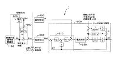
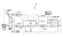
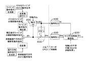
- FIG. 2 is a control block diagram of the elastic deformation compensation control apparatus 10 that controls the articulated robot 1 of FIG.
- the elastic deformation compensation control apparatus 10 includes a part realized by the host CPU and a part realized by the servo control unit.
- the elastic deformation compensation control device 10 has a plurality of joints so that a tool (here, a welding torch) attached to the articulated robot 1 performs a desired operation (here, a weaving operation). Drive the shaft.
- the elastic deformation compensation control apparatus 10 includes a joint angle command value calculation unit 100, an axial force torque calculation unit (shown as “axial force FF”) 200, and a motor angle command value calculation unit (“ 600 ”shown as“ elastic deformation compensation ”. Further, the elastic deformation compensation control apparatus 10 includes a first dynamic characteristic calculation unit (shown as “dynamic characteristic (1)”) 300 and a second dynamic characteristic calculation unit (“dynamic characteristic”) realized by the servo control unit. (2) ”) 400 and a feedback control unit (shown as" servo control FB characteristics ”) 500.
- the feedback control unit 500 includes a motor angle control unit 510 and a motor current control unit (shown as “current control”) 520.
- the characteristics of the elements in the control block are all dynamic characteristics even when there is no description of dynamic characteristics.
- the description “FB” means feedback, and the description “FF” means feed forward.
- the joint angle command value calculation unit 100 calculates and outputs a joint angle command value ⁇ lc of each joint axis for realizing the weaving operation of the welding torch.
- the axial force torque calculator 200 calculates the axial force torque fc acting on each joint axis generated when operating according to the joint angle command value ⁇ lc output from the joint angle command value calculator 100 based on the dynamic model. Calculate and output from the joint angle command value ⁇ lc.
- the motor angle command value calculation unit 600 calculates and outputs a motor angle command value ⁇ mc from the joint angle command value ⁇ lc and the axial force torque fc based on parameters including the stiffness parameter of the joint axis. More specifically, the axial force torque calculator 200 calculates the axial force torque fc that acts on each axis when operating according to the command value based on the joint angle command value ⁇ lc. The motor angle command value calculation unit 600 calculates the elastic deformation amount ec from the axial force torque fc based on the shaft stiffness K, the viscosity B, etc. (can be omitted because the viscosity is small). Then, motor angle command value calculation unit 600 calculates motor angle command value ⁇ mc from joint angle command value ⁇ lc and elastic deformation amount ec.
- the first dynamic characteristic calculation unit 300 performs a filtering process on the motor angle command value ⁇ mc output from the motor angle command value calculation unit 600, and outputs a processed motor angle target value ⁇ md.
- the first dynamic characteristic calculation unit 300 includes a high frequency cutoff characteristic having a cutoff frequency lower than the natural vibration frequency of the articulated robot 1.
- the second dynamic characteristic calculation unit 400 performs filtering processing on at least one of the input to the axial force torque calculation unit 200 and the output from the axial force torque calculation unit 200, and outputs the processed axial force torque compensation value fd. To do. In FIG. 2, the second dynamic characteristic calculation unit 400 filters the output from the axial force torque calculation unit 200.
- the second dynamic characteristic calculation unit 400 includes a high-frequency cutoff characteristic having a cut-off frequency lower than or equivalent to that of the first dynamic characteristic calculation unit 300.
- the motor angle control unit 510 receives the motor angle target value ⁇ md as a target value for the motor.
- the motor current controller 520 has a target value obtained by adding the axial torque compensation value fd output from the second dynamic characteristic calculator 400 to the motor torque command value output from the motor angle controller 510. Is entered as
- the elastic deformation compensation control device 10 shown in the block diagram shown in FIG. 2 has the following features.
- the second dynamic characteristic calculation unit 400 is arranged before and / or after (here, only) the axial force torque calculation unit 200 which is a nonlinear term.
- the second dynamic characteristic calculation unit 400 provides a characteristic that cuts off a high frequency band equal to or higher than the high frequency cutoff characteristic of the first dynamic characteristic calculation unit 300.
- the cutoff frequency of the second dynamic characteristic calculation unit 400 is lower than or equal to the cutoff frequency of the first dynamic characteristic calculation unit 300.
- the first dynamic characteristic calculation unit 300 can suppress a high frequency including a natural vibration component included in the joint angle command value ⁇ lc. Furthermore, the second dynamic characteristic calculation unit 400 can suppress a high frequency including a natural vibration component included in the axial force torque fc. Thereby, the high frequency vibration which generate
- the Jacobian near the singular point changes sharply, and when the joint angle changes, a high frequency of double or triple component is generated. To do.
- the nonlinear term has a square term of velocity and the like, and therefore, a high frequency component having twice or three times the joint angle is generated.
- the second dynamic characteristic calculation having a high frequency cutoff characteristic equal to or higher than the high frequency cutoff characteristic of the first dynamic characteristic calculation unit 300 is used for the axial force torque fc output from the axial force torque calculation unit 200 which is a nonlinear term.
- the axial force torque compensation value fd is processed by the unit 400. Thereby, the high frequency vibration generated in the articulated robot 1 is further suppressed.
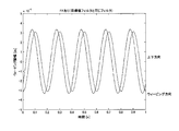
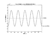
- FIG. 3 shows a weaving locus when a high frequency cutoff characteristic equivalent to that of the first dynamic characteristic calculation unit 300 is given as the high frequency cutoff characteristic of the second dynamic characteristic calculation unit 400.
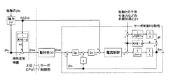
- FIG. 4 shows a control block diagram of the most common articulated robot.
- this control block includes a position control unit (Gp), a speed control unit (Gv), and a current control unit.
- the position control unit performs feedback control of the joint angle, performs proportional control (P control) of the angle deviation, and instructs the speed control unit as a speed command.
- the speed control unit feedback-controls the joint angular velocity, performs proportional-integral control (PI control) on the deviation from the given speed command, and commands the current control unit as a current control command.
- the current control unit controls the motor current based on the given current control command.
- the first dynamic characteristic calculation unit (dynamic characteristic 1) shown in FIG. 4 or the like is used so that the target value does not include a component that excites the natural vibration. These components are suppressed in the filtering process.
- the interference torque between the axes acts on each link as a nonlinear term c including a gravity term. Since the link and the motor are coupled via the speed reducer acting as a spring element, the axial force acts as an action / reaction on the link and the motor.
- the weaving operation of a welding robot it is necessary to swing the welding torch with a desired amplitude in a desired direction without shaking up and down (without causing vertical movement). Dynamic control is required. Therefore, the influence of this axial force and elastic deformation is enormous.
- FIG. 5 shows a weaving locus when the articulated robot is controlled by the control device shown by the control block in FIG.
- a nonlinear term, axial force, and elastic deformation are applied, a vertical movement occurs, which is not suitable as a weaving operation.
- FIG. 6 is a control block diagram for realizing nonlinear feedforward compensation according to the related art based on the target value based on such an idea.
- FIG. 7 shows a weaving locus when the articulated robot is controlled by the control device shown by the control block in FIG. Since this is target value-based feedforward compensation, the feedforward timing is shifted due to the influence of the phase delay, and on the contrary, the vertical movement is deteriorated.
- the host CPU performs nonlinear feedforward calculation. Since the calculation of the non-linear term is very complicated and has a large amount of calculation, and it is difficult to calculate it by the servo control unit, it is generally performed by the host CPU on the basis of the target value.
- FIG. 5 and FIG. 7 showing the results (weaving trajectory) by the control according to such a conventional technique
- the results (weaving trajectory) by the elastic deformation compensation control device 10 according to the present embodiment are as shown in FIG.
- the vertical movement component is generated, the vertical movement component is remarkably suppressed.
- FIG. 3 shows the results when the high-frequency cutoff characteristic in the second dynamic characteristic calculation unit 400 is made equal to the high-frequency cutoff characteristic in the first dynamic characteristic calculation unit 300.
- the first dynamic characteristic calculation unit 300 suppresses high frequencies including the natural vibration component included in the joint angle command value ⁇ lc. Further, the second dynamic characteristic calculation unit 400 suppresses a high frequency including a natural vibration component included in the axial force torque fc. As a result, vibration due to the nonlinear term in the above-described prior art is suppressed.
- the elastic deformation compensation control apparatus in an articulated robot, it is possible to compensate for the influence of elastic deformation of each axis and to perform operations such as weaving with high trajectory accuracy. it can.
- the elastic deformation compensation control device according to the present embodiment differs from the elastic deformation compensation control device 10 according to the first embodiment described above in the way of providing the first dynamic characteristic calculation unit 300.
- the second embodiment is the same as the first embodiment, and therefore, the same parts as those described above are not repeated here.
- the second dynamic characteristic calculation unit 400 is provided with a high frequency cutoff characteristic equal to or higher than that of the first dynamic characteristic calculation unit 300.
- the second dynamic characteristic calculation unit 400 is given so as to have a very strong high-frequency cutoff characteristic as in the first embodiment.
- the first dynamic characteristic calculation unit 300 is given by multiplying the dynamic characteristic of the second dynamic characteristic calculation unit 400 by the inverse characteristic of the feedback characteristic assumed in each axis servo control. This indicates that the characteristic of the first dynamic characteristic calculation unit 300 is provided so as to correspond to the characteristic obtained by dividing the characteristic in the second dynamic characteristic calculation unit 400 by the feedback control dynamic characteristic.
- dynamic characteristic 1 indicates the dynamic characteristic in the first dynamic characteristic calculation unit 300
- dynamic characteristic 2 indicates the dynamic characteristic in the second dynamic characteristic calculation unit 400. Is shown.
- the first dynamic characteristic calculation unit 300 is given by the following equation (2).
- the second dynamic characteristic calculator 400 has a strong high-frequency cutoff characteristic so that the expression (2) becomes a proper transfer function (the order of the numerator polynomial is equal to or lower than that of the denominator polynomial). Need to give.
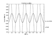
- FIG. 8 shows a weaving trajectory when the first dynamic characteristic calculation unit 300 and the second dynamic characteristic calculation unit 400 are provided in this manner. As shown in FIG. 8, in the weaving locus by the elastic deformation compensation control device according to the present embodiment, the vibration in the vertical direction is further suppressed as compared with the weaving locus in the first embodiment (FIG. 3). I understand.
- the elastic deformation compensation control device compensates for the influence of elastic deformation of each axis in an articulated robot and enables operations such as weaving with higher trajectory accuracy. Can do.
- the characteristic of the second dynamic characteristic calculation unit 400 is given as a desired dynamic characteristic (provided with a very strong high-frequency cutoff characteristic).
- the characteristic of the second dynamic characteristic calculation unit 400 is given as a characteristic obtained by dividing the desired dynamic characteristic by the current control characteristic.
- the characteristic in the second dynamic characteristic calculation unit 400 is divided by the feedback control dynamic characteristic and corresponds to the characteristic multiplied by the current control characteristic. It shows that it is comprised so that the characteristic of the 1st dynamic characteristic calculating part 300 may be given.
- the characteristic of the second dynamic characteristic calculation unit 400 is given by the following expression (3).
- the characteristic of the first dynamic characteristic calculation unit 300 expressed by the above-described expression (2) is given by the following expression (4).
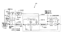
- FIG. 9 shows a control block diagram when the first dynamic characteristic calculation unit 300 and the second dynamic characteristic calculation unit 400 are provided as described above.
- the characteristic of the second dynamic characteristic calculation unit 2400 in the elastic deformation compensation control device 20 is obtained by multiplying the desired dynamic characteristic 2410 by the inverse characteristic 2420 of the current control characteristic.
- the elastic deformation compensation control apparatus according to the present modification compensates for the influence of the elastic deformation of each axis in consideration of the current control characteristics of the motor current control unit 520 in the articulated robot, Operation such as weaving can be performed with high trajectory accuracy.
- the elastic deformation compensation control device according to the present embodiment differs from the elastic deformation compensation control device 10 according to the first embodiment described above in the way of providing the first dynamic characteristic calculation unit 300.
- the second embodiment is the same as the first embodiment, and therefore, the same parts as those described above are not repeated here.
- Equation (1) is transformed into the following Equation (5).
- the cutoff frequency in the second dynamic characteristic calculation unit 400 is made lower than the cutoff frequency in the first dynamic characteristic calculation unit 300, and the characteristic in the second dynamic characteristic calculation unit 400 is changed to the feedback control dynamic characteristic (
- the first dynamic characteristic calculation unit 300 is configured to give the characteristic so as to correspond to the characteristic divided by the servo FB control dynamic characteristic.
- the feedback control dynamic characteristic from the motor angle target value ⁇ md to the actual motor angle ⁇ m in a state where there is no axial force between the axes is a parameter including at least one of the position feedback gain and the speed feedback gain. It is comprised so that it may calculate based on.
- FIG. 10 shows a weaving trajectory when the first dynamic characteristic calculation unit 300 and the second dynamic characteristic calculation unit 400 are provided in this way.
- the current control characteristic is approximated by 1, so that the performance of the weaving locus (FIG. 8) in the second embodiment is naturally. Is not enough.
- the present invention exhibits a performance that is satisfactory compared to the prior art and that can sufficiently withstand practical use.
- the current control characteristic By approximating the current control characteristic by 1 in this way, it is possible to shorten the calculation time while satisfying performance that can sufficiently withstand practical use.
- the elastic deformation compensation control device according to the present embodiment differs from the elastic deformation compensation control device 10 according to the first embodiment described above in the way of providing the first dynamic characteristic calculation unit 300.
- the second embodiment is the same as the first embodiment, and therefore, the same parts as those described above are not repeated here.
- the phase lag of the first dynamic characteristic calculation unit 300 of the axis with a slow response of the motor angle control unit 510 is the first delay of the axis with the quick response of the motor angle control unit 510.
- the dynamic characteristic calculation unit 300 is configured to be shorter than the phase delay.
- desired dynamic characteristics are given to each axis. However, in the actual weaving operation, it is necessary to align the dynamic characteristics of each axis. For this purpose, the same (common) desired dynamic characteristic may be given to all axes. In FIG. 8 and FIG. 10 described above, the same desired dynamic characteristics are already given to all axes.
- FIG. 11 shows a weaving locus when a desired dynamic characteristic is slightly changed for each axis.
- FIG. 11 it can be seen that vertical motion occurs when the response of each axis is changed by changing the dynamic characteristics for each axis. That is, the results of the first to third embodiments (and the prior art) described above are the results obtained by aligning the responses of the respective axes, and when the responses of the respective axes are not aligned, the weaving accuracy is deteriorated.
- the desired dynamic characteristics are the same for all axes.
- the reverse characteristic of the servo FB control dynamic characteristic is multiplied by the “dynamic characteristic 1”, so that the axis with the slow servo FB control dynamic characteristic is compared with the fast axis.
- the response of “dynamic characteristic 1” becomes faster.
- the response of “dynamic characteristic 1” is delayed in the axis having the fast servo FB control dynamic characteristics compared to the slow axis.
- the elastic deformation compensation control apparatus slows the “dynamic characteristic 1” of the fast axis as compared with the slow axis of the servo FB control dynamic characteristics, so that the same dynamic characteristics are obtained for all axes from the state of FIG. Can be gradually approximated to the state of FIG. 3, FIG. 8, or FIG.
- the elastic deformation compensation control device according to the present embodiment is added with speed feedforward control and / or acceleration feedforward control that the elastic deformation compensation control device 10 according to the first embodiment described above does not have. Is different.
- the second embodiment is the same as the first embodiment, and therefore, the same parts as those described above are not repeated here.
- the speed feedforward control and / or the acceleration feedforward control is not provided.
- the elastic deformation compensation control device 30 according to the present embodiment includes speed feedforward control and acceleration feedforward control.
- FIG. 12 is a block diagram of an elastic deformation compensation control device 30 according to the fifth embodiment.
- the elastic deformation compensation control device 30 includes speed feedforward control and acceleration feedforward control.
- the elastic deformation compensation control device 30 includes a motor angle control unit 3510 instead of the motor angle control unit 510.
- the expression (1) is given by the following expression (7).
- Gda and Gdv are acceleration feed forward and velocity feed forward gains, and take values of 0 to 1.
- Jd is a predicted value of Jm.
- the current control characteristics can also be calculated from the current control gain and the motor parameters (inductance and resistance).
- velocity feedforward control and acceleration feedforward control are added to compensate for the elastic deformation effect of each axis, and weaving with high trajectory accuracy. Etc. can be made possible.
- a second dynamic characteristic calculation unit 4400 is arranged before and after the axial force torque calculation unit 200 which is a nonlinear term. More specifically, the dynamic characteristic (21) 4410 is disposed before the axial force torque calculation unit 200, and the dynamic characteristic (22) 4420 is disposed after the axial force torque calculation unit 200.
- ⁇ le is an output value when the joint angle command value ⁇ lc is input to the dynamic characteristic (21) 4410.
- the output value when the axial force torque fc calculated by the axial force torque calculator 200 based on this ⁇ le is input to the dynamic characteristic (22) 4420 is the axial force torque compensation value fd.
- the second dynamic characteristic calculation unit arranged in a divided manner compensates for the elastic deformation of each axis in the articulated robot.
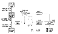
- FIG. 14 and 15 are control block diagrams of the elastic deformation compensation control apparatus according to the present embodiment.
- the control block shown in FIG. 14 and the control block shown in FIG. 15 differ in the number and position of inverse transform (inverse Jacobian) elements.
- inverse Jacobian inverse Jacobian
- the weaving operation is performed according to the given “dynamic characteristic 2”. It is possible to reversely calculate the gain characteristic and the phase characteristic in the period. By correcting the weaving command according to the characteristics, a desired weaving operation can be realized.
- the elastic deformation compensation control device is different from the above-described elastic deformation compensation control device 10 according to the first embodiment in that an axial force torque calculation value or an elastic deformation amount calculation value and a joint angle command value are used. Is different in that the phase difference is matched.
- the second embodiment is the same as the first embodiment, and therefore, the same parts as those described above are not repeated here.
- the following processing is performed.
- motor angle command value calculation unit 600 the phase difference between the axial force torque calculated value or elastic deformation amount calculated value and the joint angle command value is matched, and the axial force torque calculated value or elastic deformation amount calculated value and phase correction after phase correction are performed.
- a motor angle command value is calculated from the subsequent joint angle command value.
- the elastic deformation compensation control device When calculating the axial force, the speed and acceleration of the joint angle are required. Usually, the speed and acceleration calculated by the difference process are used for these. In the axial force torque calculation unit 200 for calculating the axial force, the process is performed at a cycle dT that is much slower than the servo control cycle, so the influence of the phase delay due to the difference is very large, and phase correction is performed to align these phases. Is done.
- the phases can be aligned by deriving the velocity from the following equation (9).
- the elastic deformation amount ec is calculated using the joint angle command value ⁇ lc with the phase adjusted, and when calculating the motor command value, the elastic deformation amount ec with respect to the joint angle command value ⁇ lc with the phase adjusted.
- the motor angle command value ⁇ mc may be calculated after correction.
- an elastic deformation compensation control device configured as follows, in an articulated robot in which a motor and an arm are coupled via an elastically deforming speed reducer, Operation such as weaving can be performed with high trajectory accuracy.
- a low-pass filter characteristic that cuts off the natural vibration period from the target value is given, the vibration component is removed from the target angle, and the axial force torque is also low-pass filtered. Thereby, the phase of the target value and the axial force torque are aligned, and elastic deformation compensation is performed while suppressing vibration.
- the phase of the target value and the axial force torque are aligned, and elastic deformation compensation is performed while suppressing vibrations.
- weaving amplitude correction is performed every weaving cycle.
Landscapes
- Engineering & Computer Science (AREA)
- Mechanical Engineering (AREA)
- Robotics (AREA)
- Physics & Mathematics (AREA)
- Plasma & Fusion (AREA)
- Manipulator (AREA)
- Numerical Control (AREA)
Priority Applications (4)
| Application Number | Priority Date | Filing Date | Title |
|---|---|---|---|
| US14/403,320 US9505131B2 (en) | 2012-05-30 | 2013-05-30 | Elastic-deformation-compensation control device and control method for articulated robot |
| CN201380028233.6A CN104349873B (zh) | 2012-05-30 | 2013-05-30 | 多关节机器人的弹性变形补偿控制装置以及控制方法 |
| EP13796876.4A EP2857151B1 (de) | 2012-05-30 | 2013-05-30 | Steuerungsvorrichtung für den ausgleich der elastischen deformation für einen schwenkroboter und steuerungsverfahren |
| KR1020147033246A KR101612218B1 (ko) | 2012-05-30 | 2013-05-30 | 다관절 로봇의 탄성 변형 보상 제어 장치 및 제어 방법 |
Applications Claiming Priority (2)
| Application Number | Priority Date | Filing Date | Title |
|---|---|---|---|
| JP2012-123239 | 2012-05-30 | ||
| JP2012123239A JP5374613B2 (ja) | 2012-05-30 | 2012-05-30 | 多関節ロボットの弾性変形補償制御装置および制御方法 |
Publications (1)
| Publication Number | Publication Date |
|---|---|
| WO2013180223A1 true WO2013180223A1 (ja) | 2013-12-05 |
Family
ID=49673410
Family Applications (1)
| Application Number | Title | Priority Date | Filing Date |
|---|---|---|---|
| PCT/JP2013/065057 WO2013180223A1 (ja) | 2012-05-30 | 2013-05-30 | 多関節ロボットの弾性変形補償制御装置および制御方法 |
Country Status (6)
| Country | Link |
|---|---|
| US (1) | US9505131B2 (de) |
| EP (1) | EP2857151B1 (de) |
| JP (1) | JP5374613B2 (de) |
| KR (1) | KR101612218B1 (de) |
| CN (1) | CN104349873B (de) |
| WO (1) | WO2013180223A1 (de) |
Cited By (2)
| Publication number | Priority date | Publication date | Assignee | Title |
|---|---|---|---|---|
| CN106457560A (zh) * | 2014-06-02 | 2017-02-22 | 株式会社神户制钢所 | 机器人的控制装置 |
| WO2018079075A1 (ja) * | 2016-10-24 | 2018-05-03 | パナソニックIpマネジメント株式会社 | エンコーダの異常検出方法及び異常検出装置、並びにロボット制御システム |
Families Citing this family (22)
| Publication number | Priority date | Publication date | Assignee | Title |
|---|---|---|---|---|
| JP5409844B2 (ja) * | 2012-05-30 | 2014-02-05 | 株式会社神戸製鋼所 | 多関節ロボットの軌跡制御装置および制御方法 |
| JP5916583B2 (ja) * | 2012-10-19 | 2016-05-11 | 株式会社神戸製鋼所 | 多関節ロボットのウィービング制御装置 |
| JP5642214B2 (ja) * | 2013-02-15 | 2014-12-17 | 株式会社神戸製鋼所 | 多関節ロボットの弾性変形補償制御装置 |
| AT514116A1 (de) * | 2013-04-09 | 2014-10-15 | Ttcontrol Gmbh | Regelsystem und Verfahren zum Steuern der Orientierung eines Segments eines Manipulators |
| US9718187B2 (en) * | 2014-06-11 | 2017-08-01 | Canon Kabushiki Kaisha | Robot controlling method, robot apparatus, program, recording medium, and method for manufacturing assembly component |
| US9505132B1 (en) * | 2015-03-30 | 2016-11-29 | X Development Llc | Methods and systems for calibrating a sensor of a robotic device |
| EP3131202A1 (de) * | 2015-08-11 | 2017-02-15 | Siemens Aktiengesellschaft | Filterumschaltverfahren für eine maschinensteuerung |
| US10350766B2 (en) * | 2015-09-21 | 2019-07-16 | GM Global Technology Operations LLC | Extended-reach assist device for performing assembly tasks |
| DE102017000063B4 (de) * | 2016-01-14 | 2019-10-31 | Fanuc Corporation | Robotereinrichtung mit Lernfunktion |
| DE112016006602T5 (de) * | 2016-03-16 | 2018-12-13 | Mitsubishi Electric Corporation | Maschinenbewegungsbahnverlaufsmessvorrichtung |
| CN107538494A (zh) * | 2016-06-29 | 2018-01-05 | 沈阳新松机器人自动化股份有限公司 | 一种基于转矩传感器和编码器的机器人控制方法及系统 |
| JP6386501B2 (ja) * | 2016-08-12 | 2018-09-05 | ファナック株式会社 | レーザ加工ロボットシステム及びレーザ加工方法 |
| DE102017005581B4 (de) | 2017-06-13 | 2019-02-21 | Kuka Deutschland Gmbh | Steuern eines Roboters |
| WO2019012942A1 (ja) * | 2017-07-11 | 2019-01-17 | パナソニックIpマネジメント株式会社 | ロボット制御装置 |
| CN108638056A (zh) * | 2018-04-13 | 2018-10-12 | 华南理工大学 | 基于柔体动力学模型的机器人关节振动分析与抑制方法 |
| JP7338960B2 (ja) * | 2018-09-27 | 2023-09-05 | ニデックインスツルメンツ株式会社 | サーボ制御装置及びサーボ制御方法 |
| CN110053050A (zh) * | 2019-04-22 | 2019-07-26 | 珠海格力智能装备有限公司 | 机器人轨迹精度的补偿方法及装置、存储介质、处理器 |
| CN110450171B (zh) * | 2019-09-09 | 2020-12-08 | 北京配天技术有限公司 | 焊接机器人及其摆动轨迹的规划方法 |
| CN111673611B (zh) * | 2020-05-26 | 2021-06-18 | 华中科技大学 | 飞机复材构件机器人磨抛加工弹性变形及振动抑制方法 |
| JP7126576B1 (ja) * | 2021-02-16 | 2022-08-26 | 株式会社牧野フライス製作所 | 送り軸の制御方法および装置 |
| JP2022127016A (ja) * | 2021-02-19 | 2022-08-31 | 株式会社神戸製鋼所 | バネ定数補正装置、該方法および該プログラム |
| CN114029787B (zh) * | 2021-11-08 | 2022-11-25 | 陕西科控技术产业研究院有限公司 | 一种半闭环控制方式下数控机床进给系统弹性变形补偿方法 |
Citations (8)
| Publication number | Priority date | Publication date | Assignee | Title |
|---|---|---|---|---|
| JPS61201304A (ja) | 1985-03-04 | 1986-09-06 | Matsushita Electric Ind Co Ltd | ロボツトの位置制御法 |
| JPS63212483A (ja) * | 1987-02-27 | 1988-09-05 | 株式会社東芝 | 多自由度マニピユレ−タの制御装置 |
| JPH106261A (ja) * | 1996-06-18 | 1998-01-13 | Sony Corp | ロボット制御装置 |
| JPH10217173A (ja) * | 1997-02-07 | 1998-08-18 | Yaskawa Electric Corp | ロボットの非干渉化制御装置 |
| JPH10329063A (ja) * | 1997-05-28 | 1998-12-15 | Yaskawa Electric Corp | ロボット制御装置 |
| JP2003280703A (ja) * | 2002-03-26 | 2003-10-02 | Kobe Steel Ltd | 推定装置を用いた制御装置 |
| JP2005102427A (ja) * | 2003-09-25 | 2005-04-14 | Kobe Steel Ltd | 衝突検知方法及び衝突検知装置 |
| JP2005186235A (ja) | 2003-12-26 | 2005-07-14 | Yaskawa Electric Corp | ロボットの制御装置 |
Family Cites Families (11)
| Publication number | Priority date | Publication date | Assignee | Title |
|---|---|---|---|---|
| US4829219A (en) * | 1986-11-20 | 1989-05-09 | Unimation Inc. | Multiaxis robot having improved motion control through variable acceleration/deceleration profiling |
| JP3473834B2 (ja) * | 1999-11-29 | 2003-12-08 | 株式会社安川電機 | ロボットの制御装置 |
| EP1132790B1 (de) * | 2000-02-10 | 2003-06-18 | Fanuc Ltd | Steuervorrichtung für eine Maschine |
| JP4536349B2 (ja) * | 2003-09-22 | 2010-09-01 | パナソニック株式会社 | 弾性体アクチュエータを用いた多自由度のロボットアームの制御装置及び制御方法 |
| JP2008296310A (ja) * | 2007-05-30 | 2008-12-11 | Fanuc Ltd | 加工ロボットの制御装置 |
| JP5024383B2 (ja) * | 2008-05-21 | 2012-09-12 | パナソニック株式会社 | ロボットの異常判定方法 |
| DE102009054112A1 (de) * | 2009-11-20 | 2011-05-26 | Kuka Roboter Gmbh | Verfahren und Vorrichtung zur Planung und/oder Steuerung einer Roboterapplikation |
| JP5214578B2 (ja) * | 2009-12-02 | 2013-06-19 | 本田技研工業株式会社 | 動力装置の制御装置 |
| JP5043239B2 (ja) * | 2010-01-15 | 2012-10-10 | パナソニック株式会社 | 弾性体アクチュエータ駆動機構の制御装置及び制御方法、並びに、制御プログラム |
| JP5409844B2 (ja) * | 2012-05-30 | 2014-02-05 | 株式会社神戸製鋼所 | 多関節ロボットの軌跡制御装置および制御方法 |
| JP5642214B2 (ja) * | 2013-02-15 | 2014-12-17 | 株式会社神戸製鋼所 | 多関節ロボットの弾性変形補償制御装置 |
-
2012
- 2012-05-30 JP JP2012123239A patent/JP5374613B2/ja active Active
-
2013
- 2013-05-30 KR KR1020147033246A patent/KR101612218B1/ko active IP Right Grant
- 2013-05-30 EP EP13796876.4A patent/EP2857151B1/de active Active
- 2013-05-30 CN CN201380028233.6A patent/CN104349873B/zh active Active
- 2013-05-30 US US14/403,320 patent/US9505131B2/en active Active
- 2013-05-30 WO PCT/JP2013/065057 patent/WO2013180223A1/ja active Application Filing
Patent Citations (8)
| Publication number | Priority date | Publication date | Assignee | Title |
|---|---|---|---|---|
| JPS61201304A (ja) | 1985-03-04 | 1986-09-06 | Matsushita Electric Ind Co Ltd | ロボツトの位置制御法 |
| JPS63212483A (ja) * | 1987-02-27 | 1988-09-05 | 株式会社東芝 | 多自由度マニピユレ−タの制御装置 |
| JPH106261A (ja) * | 1996-06-18 | 1998-01-13 | Sony Corp | ロボット制御装置 |
| JPH10217173A (ja) * | 1997-02-07 | 1998-08-18 | Yaskawa Electric Corp | ロボットの非干渉化制御装置 |
| JPH10329063A (ja) * | 1997-05-28 | 1998-12-15 | Yaskawa Electric Corp | ロボット制御装置 |
| JP2003280703A (ja) * | 2002-03-26 | 2003-10-02 | Kobe Steel Ltd | 推定装置を用いた制御装置 |
| JP2005102427A (ja) * | 2003-09-25 | 2005-04-14 | Kobe Steel Ltd | 衝突検知方法及び衝突検知装置 |
| JP2005186235A (ja) | 2003-12-26 | 2005-07-14 | Yaskawa Electric Corp | ロボットの制御装置 |
Non-Patent Citations (1)
| Title |
|---|
| See also references of EP2857151A4 |
Cited By (5)
| Publication number | Priority date | Publication date | Assignee | Title |
|---|---|---|---|---|
| CN106457560A (zh) * | 2014-06-02 | 2017-02-22 | 株式会社神户制钢所 | 机器人的控制装置 |
| CN106457560B (zh) * | 2014-06-02 | 2018-12-18 | 株式会社神户制钢所 | 机器人的控制装置 |
| WO2018079075A1 (ja) * | 2016-10-24 | 2018-05-03 | パナソニックIpマネジメント株式会社 | エンコーダの異常検出方法及び異常検出装置、並びにロボット制御システム |
| JPWO2018079075A1 (ja) * | 2016-10-24 | 2019-09-12 | パナソニックIpマネジメント株式会社 | エンコーダの異常検出方法及び異常検出装置、並びにロボット制御システム |
| US11241792B2 (en) | 2016-10-24 | 2022-02-08 | Panasonic Intellectual Property Management Co., Ltd. | Method and device for detecting abnormality of encoder, and robot control system |
Also Published As
| Publication number | Publication date |
|---|---|
| KR101612218B1 (ko) | 2016-04-12 |
| EP2857151B1 (de) | 2017-07-05 |
| EP2857151A1 (de) | 2015-04-08 |
| JP5374613B2 (ja) | 2013-12-25 |
| CN104349873B (zh) | 2015-11-25 |
| EP2857151A4 (de) | 2016-07-20 |
| US9505131B2 (en) | 2016-11-29 |
| JP2013248681A (ja) | 2013-12-12 |
| US20150105905A1 (en) | 2015-04-16 |
| KR20150006017A (ko) | 2015-01-15 |
| CN104349873A (zh) | 2015-02-11 |
Similar Documents
| Publication | Publication Date | Title |
|---|---|---|
| JP5374613B2 (ja) | 多関節ロボットの弾性変形補償制御装置および制御方法 | |
| JP5409844B2 (ja) | 多関節ロボットの軌跡制御装置および制御方法 | |
| JP5916583B2 (ja) | 多関節ロボットのウィービング制御装置 | |
| KR101864062B1 (ko) | 로봇의 제어 장치 | |
| JPH02310609A (ja) | マニピユレータの位置と力の協調制御装置 | |
| CN111095132B (zh) | 伺服控制装置 | |
| JP5642214B2 (ja) | 多関節ロボットの弾性変形補償制御装置 | |
| JP4781000B2 (ja) | サーボ制御装置 | |
| JP6998514B2 (ja) | ロボット制御装置 | |
| JP5868266B2 (ja) | 多関節ロボットの弾性変形補償制御装置および制御方法 | |
| KR100342256B1 (ko) | 로봇제어시스템 및 그 제어방법 |
Legal Events
| Date | Code | Title | Description |
|---|---|---|---|
| 121 | Ep: the epo has been informed by wipo that ep was designated in this application |
Ref document number: 13796876 Country of ref document: EP Kind code of ref document: A1 |
|
| WWE | Wipo information: entry into national phase |
Ref document number: 14403320 Country of ref document: US |
|
| ENP | Entry into the national phase |
Ref document number: 20147033246 Country of ref document: KR Kind code of ref document: A |
|
| NENP | Non-entry into the national phase |
Ref country code: DE |
|
| REEP | Request for entry into the european phase |
Ref document number: 2013796876 Country of ref document: EP |