EP2848101B1 - Thermoelektrische wärmetauscherkomponente mit wärmeverteilungsschutzklappe und optimalem thermischem grenzflächenwiderstand - Google Patents
Thermoelektrische wärmetauscherkomponente mit wärmeverteilungsschutzklappe und optimalem thermischem grenzflächenwiderstand Download PDFInfo
- Publication number
- EP2848101B1 EP2848101B1 EP13724983.5A EP13724983A EP2848101B1 EP 2848101 B1 EP2848101 B1 EP 2848101B1 EP 13724983 A EP13724983 A EP 13724983A EP 2848101 B1 EP2848101 B1 EP 2848101B1
- Authority
- EP
- European Patent Office
- Prior art keywords
- thermoelectric
- heat spreading
- thermoelectric devices
- spreading lid
- heat
- Prior art date
- Legal status (The legal status is an assumption and is not a legal conclusion. Google has not performed a legal analysis and makes no representation as to the accuracy of the status listed.)
- Active
Links
Images


Classifications
-
- F—MECHANICAL ENGINEERING; LIGHTING; HEATING; WEAPONS; BLASTING
- F25—REFRIGERATION OR COOLING; COMBINED HEATING AND REFRIGERATION SYSTEMS; HEAT PUMP SYSTEMS; MANUFACTURE OR STORAGE OF ICE; LIQUEFACTION SOLIDIFICATION OF GASES
- F25B—REFRIGERATION MACHINES, PLANTS OR SYSTEMS; COMBINED HEATING AND REFRIGERATION SYSTEMS; HEAT PUMP SYSTEMS
- F25B21/00—Machines, plants or systems, using electric or magnetic effects
-
- H—ELECTRICITY
- H05—ELECTRIC TECHNIQUES NOT OTHERWISE PROVIDED FOR
- H05K—PRINTED CIRCUITS; CASINGS OR CONSTRUCTIONAL DETAILS OF ELECTRIC APPARATUS; MANUFACTURE OF ASSEMBLAGES OF ELECTRICAL COMPONENTS
- H05K1/00—Printed circuits
- H05K1/18—Printed circuits structurally associated with non-printed electric components
- H05K1/182—Printed circuits structurally associated with non-printed electric components associated with components mounted in the printed circuit board, e.g. insert mounted components [IMC]
-
- F—MECHANICAL ENGINEERING; LIGHTING; HEATING; WEAPONS; BLASTING
- F25—REFRIGERATION OR COOLING; COMBINED HEATING AND REFRIGERATION SYSTEMS; HEAT PUMP SYSTEMS; MANUFACTURE OR STORAGE OF ICE; LIQUEFACTION SOLIDIFICATION OF GASES
- F25B—REFRIGERATION MACHINES, PLANTS OR SYSTEMS; COMBINED HEATING AND REFRIGERATION SYSTEMS; HEAT PUMP SYSTEMS
- F25B21/00—Machines, plants or systems, using electric or magnetic effects
- F25B21/02—Machines, plants or systems, using electric or magnetic effects using Peltier effect; using Nernst-Ettinghausen effect
-
- H—ELECTRICITY
- H05—ELECTRIC TECHNIQUES NOT OTHERWISE PROVIDED FOR
- H05K—PRINTED CIRCUITS; CASINGS OR CONSTRUCTIONAL DETAILS OF ELECTRIC APPARATUS; MANUFACTURE OF ASSEMBLAGES OF ELECTRICAL COMPONENTS
- H05K1/00—Printed circuits
- H05K1/02—Details
- H05K1/0201—Thermal arrangements, e.g. for cooling, heating or preventing overheating
- H05K1/0203—Cooling of mounted components
- H05K1/0204—Cooling of mounted components using means for thermal conduction connection in the thickness direction of the substrate
-
- H—ELECTRICITY
- H05—ELECTRIC TECHNIQUES NOT OTHERWISE PROVIDED FOR
- H05K—PRINTED CIRCUITS; CASINGS OR CONSTRUCTIONAL DETAILS OF ELECTRIC APPARATUS; MANUFACTURE OF ASSEMBLAGES OF ELECTRICAL COMPONENTS
- H05K2201/00—Indexing scheme relating to printed circuits covered by H05K1/00
- H05K2201/06—Thermal details
- H05K2201/066—Heatsink mounted on the surface of the PCB
-
- H—ELECTRICITY
- H05—ELECTRIC TECHNIQUES NOT OTHERWISE PROVIDED FOR
- H05K—PRINTED CIRCUITS; CASINGS OR CONSTRUCTIONAL DETAILS OF ELECTRIC APPARATUS; MANUFACTURE OF ASSEMBLAGES OF ELECTRICAL COMPONENTS
- H05K2201/00—Indexing scheme relating to printed circuits covered by H05K1/00
- H05K2201/10—Details of components or other objects attached to or integrated in a printed circuit board
- H05K2201/10007—Types of components
- H05K2201/10219—Thermoelectric component
-
- Y—GENERAL TAGGING OF NEW TECHNOLOGICAL DEVELOPMENTS; GENERAL TAGGING OF CROSS-SECTIONAL TECHNOLOGIES SPANNING OVER SEVERAL SECTIONS OF THE IPC; TECHNICAL SUBJECTS COVERED BY FORMER USPC CROSS-REFERENCE ART COLLECTIONS [XRACs] AND DIGESTS
- Y10—TECHNICAL SUBJECTS COVERED BY FORMER USPC
- Y10T—TECHNICAL SUBJECTS COVERED BY FORMER US CLASSIFICATION
- Y10T29/00—Metal working
- Y10T29/49—Method of mechanical manufacture
- Y10T29/49002—Electrical device making
Definitions
- the present disclosure relates to a thermoelectric heat exchanger.
- Thin film thermoelectric devices are typically much smaller and more fragile than comparable bulk-type thermoelectric modules.
- An area for a typical thin film thermoelectric device is on the order of 140 square millimeters (mm 2 ) whereas an area of a typical bulk-type thermoelectric module is on the order of 1,600 mm 2 .
- Thin film thermoelectric devices can be disposed between heat sinks to form a thermoelectric heat exchanger.
- a thermal resistance of a thermal interface material between a thermoelectric device and an attached heat sink is defined as I/kA, where I is a thickness of the thermal interface material, k is a thermal conductivity of the thermal interface material, and A is an area of an interface between the thermoelectric device and the heat sink.
- the thermal resistance of the thermal interface material between a thin film thermoelectric device and a heat sink is on the order of 10 times higher than the thermal resistance of the thermal interface material between a larger bulk-type thermoelectric module and a corresponding heat sink.
- the higher thermal resistance of the thermal interface material results in a higher hot side temperature and requires a lower cold side temperature, which leads to higher power consumption and/or inability to cool adequately.
- thin film thermoelectric devices cannot withstand as much mechanical loading as bulk-type thermoelectric modules. Further, thin film thermoelectric devices cannot withstand uneven mechanical loading.
- heat sinks attached to both sides of thin film thermoelectric devices tend to be quite large compared to the thin film thermoelectric devices and are often constrained in a given product. As such, it is difficult to get even, controlled loading on a thin film thermoelectric device.
- EP 1505662 discloses a thermoelectric device in which a plurality of heat-radiating-side electrodes are arrayed on a planar surface of a heat-radiating-side board in accordance with positions where respective thermoelectric elements are to be arranged. Heat-radiating-side end surfaces of the plurality of thermoelectric elements and the heat-radiating-side electrodes are joined together by solders. Heat-absorbing-side electrodes are brought into sliding contact with heat-absorbing-side end surfaces of these thermoelectric elements.
- a thermoelectric heat exchanger component includes a circuit board and multiple thermoelectric devices attached to the circuit board. Heights of at least two of the thermoelectric devices are different due to, for example, tolerances in a manufacturing process for the thermoelectric devices.
- the thermoelectric heat exchanger also includes a heat spreading lid over the thermoelectric devices and a thermal interface material between the thermoelectric devices and the heat spreading lid.
- An orientation (i.e., a tilt) of the heat spreading lid is such that a thickness of the thermal interface material, and thus a thermal interface resistance, is minimized for the thermoelectric devices, which in turn minimizes the thermal interface resistance of the thermal interface material between the thermoelectric devices and the heat spreading lid.
- the heat spreading lid includes a body and multiple pedestals of equal heights relative to the body of the heat spreading lid that extend from the body of the heat spreading lid toward the thermoelectric devices. Each of the pedestals is aligned with a corresponding one of the thermoelectric devices.
- the thermal interface material is between a surface of each pedestal and a surface of the corresponding thermoelectric device, and the orientation of the heat spreading lid is in accordance with the respective heights of the plurality of thermoelectric devices such that the thickness of the thermal interface material between each pedestal and the corresponding thermoelectric device is minimized.
- the heat spreading lid further includes a lip that extends from the body of the heat spreading lid around a periphery of the heat spreading lid.
- a height of the lip relative to the body of the heat spreading lid is such that, for any combination of heights of the thermoelectric devices within a predefined range, at least a predefined minimum gap is maintained between the lip of the heat spreading lid and the circuit board, wherein the predefined minimum gap is greater than zero.
- thermoelectric devices are attached to a first surface of the circuit board, and the heat spreading lid is over surfaces of the thermoelectric devices opposite the first surface of the circuit board.
- thermoelectric devices are attached to a first surface of the circuit board, and the heat spreading lid is over surfaces of the thermoelectric devices exposed at a second surface of the circuit board through one or more holes through the circuit board.
- thermoelectric devices are attached to a first surface of the circuit board, and the heat spreading lid is over surfaces of the thermoelectric devices opposite the first surface of the circuit board.
- thermoelectric heat exchanger component further comprises a second heat spreading lid over surfaces of the thermoelectric devices exposed at a second surface of the circuit board through one or more holes through the circuit board.
- thermoelectric heat exchanger component is fabricated by attaching multiple thermoelectric devices to a circuit board. Two or more of the thermoelectric devices have different heights due to, for example, tolerances in a manufacturing process of the thermoelectric devices.
- a thermal interface material is applied to surfaces of the thermoelectric devices and/or a heat spreading lid.
- the heat spreading lid is then positioned over the thermoelectric devices, and a ball point force is applied to the heat spreading lid. As a result of the ball point force, the heat spreading lid settles at an in accordance with the respective heights of the plurality of the thermoelectric devices, at which a thickness of the thermal interface material is minimized for the thermoelectric devices.
- thermoelectric heat exchanger component having a heat spreading lid that optimizes thermal interface resistance between the heat spreading lid and multiple thermoelectric devices and methods of fabrication thereof are disclosed. It should be noted that while much of the discussion herein focuses on embodiments of a thermoelectric heat exchanger including thermoelectric coolers (TECs), the concepts disclosed herein are equally applicable to other types of thermoelectric devices such as, for example, thermoelectric power generators (TEGs) utilized to generate power from recovered heat.
- TECs thermoelectric coolers
- TEGs thermoelectric power generators
- thermoelectric heat exchanger component 14 can be utilized in any suitable thermoelectric system
- Figure 1 illustrates a thermoelectric refrigeration system 10 that includes a heat exchanger 12 having a thermoelectric heat exchanger component 14 according to one exemplary embodiment of the present disclosure.
- the thermoelectric refrigeration system 10 includes the heat exchanger 12, a cooling chamber 16, and a controller 18 that controls cooling within the cooling chamber 16.
- the heat exchanger 12 includes a hot side heat sink 20, a cold side heat sink 22, and the thermoelectric heat exchanger component 14 disposed between the hot side heat sink 20 and the cold side heat sink 22.
- the thermoelectric heat exchanger component 14 includes multiple thin film thermoelectric devices, which in the thermoelectric refrigeration system 10 are thin film TECs.
- Each of the TECs has a hot side thermally coupled to the hot side heat sink 20 and a cold side that is thermally coupled to the cold side heat sink 22.
- the activated TEC(s) operates to cool the cold side heat sink 22 and reject heat to the hot side heat sink 20 to thereby facilitate heat transfer to extract heat from the cooling chamber 16. More specifically, when one or more of the TECs are activated, the hot side heat sink 20 is heated to thereby create an evaporator and the cold side heat sink 22 is cooled to thereby create a condenser.
- the cold side heat sink 22 facilitates heat extraction from the cooling chamber 16 via an accept loop 24 coupled with the cold side heat sink 22.
- the accept loop 24 is thermally coupled to an interior wall 26 of the thermoelectric refrigeration system 10 that defines the cooling chamber 16.
- the accept loop 24 is either integrated into the interior wall 26 or integrated directly onto the surface of the interior wall 26.
- the accept loop 24 is formed by any type of plumbing that allows for a working fluid, which is referred to herein as a cooling medium (e.g., a two-phase coolant), to flow or pass through the accept loop 24. Due to the thermal coupling of the accept loop 24 and the interior wall 26, the cooling medium extracts heat from the cooling chamber 16 as the cooling medium flows through the accept loop 24.
- the accept loop 24 may be formed of, for example, copper tubing, plastic tubing, stainless steel tubing, aluminum tubing, or the like.
- the condenser formed by the cold side heat sink 22 and the accept loop 24 operates according to any suitable heat exchange technique.
- the accept loop 24 operates in accordance with thermosiphon principles (i.e., acts as a thermosiphon) such that the cooling medium travels from the cold side heat sink 22 through the accept loop 24 and back to the cold side heat sink 22 to thereby cool the cooling chamber 16 using two-phase, passive heat transport.
- passive heat exchange occurs through natural convection between the cooling medium in the accept loop 24 and the cooling chamber 16.
- the cooling medium is condensed inside the cold side heat sink 22.
- the condensed cooling medium flows through the accept loop 24 via gravity forces.
- the accept loop 24 passive heat exchange occurs between the environment in the cooling chamber 16 and the condensed cooling medium within the accept loop 24 such that the temperature in the cooling chamber 16 decreases and the temperature of the cooling medium increases and/or undergoes a phase change.
- the accept loop 24 functions as an evaporator when cooling the cooling chamber 16.
- the evaporated cooling medium moves in an upward direction via buoyancy forces in the accept loop 24 towards the cold side heat sink 22.
- the evaporated cooling medium comes into thermal contact with the cold side heat sink 22, where heat exchange occurs between the cooling medium and the cold side heat sink 22.
- the cooling medium condenses and again flows through the accept loop 24 via gravity in order to extract additional heat from the cooling chamber 16.
- the heat exchanger 12 includes the thermoelectric heat exchanger component 14 disposed between the hot side heat sink 20 and the cold side heat sink 22.
- the TECs in the thermoelectric heat exchanger component 14 have hot sides (i.e., sides that are hot during operation of the TECs) that are thermally coupled with the hot side heat sink 20 and cold sides (i.e., sides that are cold during operation of the TECs) that are thermally coupled with the cold side heat sink 22.
- the TECs within the thermoelectric heat exchanger component 14 effectively facilitate heat transfer between the cold side heat sink 22 and the hot side heat sink 20. More specifically, when heat transfer occurs between the cooling medium in the accept loop 24 and the cold side heat sink 22, the active TECs transfer heat between the cold side heat sink 22 and the hot side heat sink 20.
- the hot side heat sink 20 facilitates rejection of heat to an environment external to the cooling chamber 16 via a reject loop 28 coupled to the hot side heat sink 20.
- the reject loop 28 is thermally coupled to an outer wall 30, or outer skin, of the thermoelectric refrigeration system 10.
- the outer wall 30 is thermally isolated from the accept loop 24 and the interior wall 26 (and thus the cooling chamber 16) by, for example, appropriate insulation.
- the reject loop 28 is integrated into the outer wall 30 or integrated onto the surface (e.g., the interior surface) of the outer wall 30.
- the reject loop 28 is formed of any type of plumbing that allows a working fluid, which is referred to herein as a heat transfer medium (e.g., a two-phase coolant), to flow or pass through the reject loop 28. Due to the thermal coupling of the reject loop 28 and the external environment, the heat transfer medium rejects heat to the external environment as the heat transfer medium flows through the reject loop 28.
- the reject loop 28 may be formed of, for example, copper tubing, plastic tubing, stainless steel tubing, aluminum tubing, or the like.
- the evaporator formed by the hot side heat sink 20 and the reject loop 28 operates according to any suitable heat exchange technique.
- the reject loop 28 operates in accordance with thermosiphon principles (i.e., acts as a thermosiphon) such that the heat transfer medium travels from the hot side heat sink 20 through the reject loop 28 and back to the hot side heat sink 20 to thereby reject heat using two-phase, passive heat transport.
- passive heat exchange occurs through natural convection between the heat transfer medium in the reject loop 28 and the external environment.
- the heat transfer medium is evaporated inside the hot side heat sink 28. The evaporated heat transfer medium flows through the reject loop 28 via buoyancy forces.
- the reject loop 28 passive heat exchange occurs between the evaporated heat transfer medium inside the reject loop 28 and the external environment such that the temperature of the evaporated heat transfer medium inside the reject loop 28 decreases such that the density of the heat transfer medium increases such as through condensation.
- the reject loop 28 functions as a condenser when rejecting heat. As a result, the condensed heat transfer medium travels back through the reject loop 28 to the hot side heat sink 20 via gravity forces.
- the heat exchanger 12 is not in direct thermal contact with the cooling chamber 16 and is instead thermally isolated from the cooling chamber 16. Likewise, the heat exchanger 12 is not in direct thermal contact with the outer wall 30 and is instead thermally isolated from the outer wall 30. Accordingly, the heat exchanger 12 is thermally isolated from both the cooling chamber 16 and the outer wall 30 of the thermoelectric refrigeration system 10. Importantly, the insulation of the heat exchanger 12 and a thermal diode effect of the accept and reject loops 24 and 28 when operating according to thermosiphon principles prevents heat leak-back into the cooling chamber 16 when the TECs are deactivated.
- the controller 18 operates to control the TECs within the thermoelectric heat exchanger component 14 in order to maintain a desired set point temperature within the cooling chamber 16.
- the controller 18 operates to selectively activate/deactivate the TECs, selectively control an input current of the TECs, and/or selectively control a duty cycle of the TECs to maintain the desired set point temperature.
- the controller 18 is enabled to separately, or independently, control one or more and, in some embodiments, two or more subsets of the TECs, where each subset includes one or more different TECs.
- the controller 18 may be enabled to separately control a first individual TEC, a second individual TEC, and a group of two TECs (i.e., a first and a second individual TEC and a group of two TECs).
- the controller 18 can, for example, selectively activate one, two, three, or four TECs independently, at maximized efficiency, as demand dictates.
- thermoelectric refrigeration system 10 While not essential for understanding the concepts disclosed and claimed herein, for more information regarding the thermoelectric refrigeration system 10, the interested reader is directed to U.S. Patent Application Serial No. 13/836,525 entitled THERMOELECTRIC REFRIGERATION SYSTEM CONTROL SCHEME FOR HIGH EFFICIENCY PERFORMANCE, filed March 15, 2013; U.S. Patent Application Serial No. 13/888,791 entitled THERMOELECTRIC REFRIGERATION SYSTEM CONTROL SCHEME FOR HIGH EFFICIENCY PERFORMANCE, filed May 7, 2013; U.S. Patent Application Serial No.
- Patent Application Serial No. 13/888,820 entitled PHYSICALLY SEPARATED HOT SIDE AND COLD SIDE HEAT SINKS IN A THERMOELECTRIC REFRIGERATION SYSTEM, filed May 7, 2013; and U.S. Patent Application Serial No. 13/888,833 entitled TWO-PHASE HEAT EXCHANGER MOUNTING, filed May 7, 2013.
- FIG 2 is a more detailed illustration of the heat exchanger 12 of Figure 1 according to one embodiment of the present disclosure.
- the heat exchanger 12 includes the thermoelectric heat exchanger component 14 between the hot side heat sink 20 and the cold side heat sink 22.
- the thermoelectric heat exchanger component 14 is thermally and physically coupled to the hot side heat sink 20 by a heat spreader 32.
- the heat spreader 32 may be part of the hot side heat sink 20.
- the heat spreader 32 is separate from the hot side heat sink 20, in which case the heat spreader 32 is thermally and physically coupled to the hot side heat sink 20 via an appropriate thermal interface material (e.g., a thermal paste, a thermal grease, or the like).
- the heat spreader 32 is formed of a material having a high thermal conductivity (e.g., copper or copper aluminum) and operates to disperse heat generated at the hot sides of the TECs in the thermoelectric heat exchanger component 14, which have a relatively small surface area, to a larger area.
- a material having a high thermal conductivity e.g., copper or copper aluminum
- thermoelectric heat exchanger component 14 is thermally and physically coupled to the cold side heat sink 22 by a heat spreader 34.
- the heat spreader 34 may be part of the cold side heat sink 22.
- the heat spreader 34 is separate from the cold side heat sink 22, in which case the heat spreader 34 is thermally and physically coupled to the cold side heat sink 22 via an appropriate thermal interface material (e.g., a thermal paste, a thermal grease, or the like).
- the heat spreader 34 is formed of a material having a high thermal conductivity (e.g., copper or copper aluminum) and operates to disperse heat, or more specifically in this case cold, generated at the cold sides of the TECs in the thermoelectric heat exchanger component 14, which have a relatively small surface area, to a larger area. It should be noted that the heat spreaders 32 and 34 are optional, at least in some implementations. More specifically, as discussed below, the thermoelectric heat exchanger component 14 includes heat spreading lids that provide a heat spreading function, in which case the heat spreaders 32 and 34 may not be needed.
- thermoelectric heat exchanger component 14 includes a circuit board 36 (e.g., a printed circuit board).
- the circuit board 36 includes holes 38 that extend through the circuit board 36, i.e., from a first surface of the circuit board 36 to a second surface of the circuit board 36.
- TECs 40 are electrically and physically attached to the circuit board 36 over the holes 38 such that, in one preferred embodiment, critical sides, which in this case are the hot sides of the TECs 40, are facing away from the circuit board 36 and less critical sides, which in this case are the cold sides of the TECs 40, are exposed at the second surface of the circuit board 36 through the holes 38.
- the holes 38 enable direct thermal contact with the cold sides of the TECs 40.
- the circuit board 36 includes a conductive trace 42 that electrically connects the TECs 40 in series as well as electrical contacts 44 that enable external circuitry to provide current to the TECs 40 to thereby activate the TECs 40.
- the thermoelectric heat exchanger component 14 is not limited thereto.
- the thermoelectric heat exchanger component 14 may include any number of two or more TECs 40 connected in any desired manner. For example, all of the TECs 40 may be connected in series. As another example, two or more subsets of the TECs 40 may be connected in parallel (e.g., a set of 1 TEC 40 is in parallel with another set of 1 TEC 40 and a set of 2 TECs 40).
- the thermoelectric heat exchanger component 14 also includes a heat spreading lid 46 over the cold sides of the TECs 40.
- the heat spreading lid 46 is formed of a material(s) having high thermal conductivity (e.g., copper or copper aluminum).
- the heat spreading lid 46 is small enough to ensure planar contact with the cold side heat sink 22 (or heat spreader 34) ( Figures 1 and 2 ) but large enough to spread heat from the small surface areas of the cold sides of the TECs 40 to a much larger thermal interface area with a negligible temperature drop.
- the heat spreading lid 46 includes a body 48, pedestals 50, and a lip 52. The pedestals 50 extend from the body 48 of the heat spreading lid 46 toward the cold sides of the TECs 40.
- the heat spreading lid 46 is positioned over the cold sides of the TECs 40 such that the pedestals 50 are aligned with the cold sides of the TECs 40 exposed through the holes 38.
- the pedestals 50 of the heat spreading lid 46 are then thermally coupled to the cold sides of the corresponding TECs 40 via a thermal interface material.
- the thermal interface material is any suitable thermal interface material.
- the thermal interface material is a thermal grease.
- the thermal interface material is a solder having high thermal conductivity.
- the pedestals 50 of the heat spreading lid 46 are fabricated to have the same height relative to the body 48 of the heat spreading lid 46 and are machined to have flat surfaces.
- the pedestals 50 can take any suitable shape.
- each of the pedestals 50 is a parallelepiped.
- each of the pedestals 50 is a frustum.
- the edges of the pedestals 50 are either vertical or sloped. Sloped edges can be used to allow thermal interface material to flow along the wall of the pedestals 50 rather than toward the TECs 40.
- the edges of the pedestals 50 are sloped at an angle of 45 degrees.
- a surface area of each of the pedestals 50 is preferably slightly less (e.g., 1 to 10 percent less) than the surface area of the cold side of the corresponding TEC 40 exposed through the corresponding hole 38.
- the dimensions of each of the pedestals 50 at the interface with the corresponding TEC 40 are slightly smaller than those of the surface of the corresponding TEC 40.
- the slightly smaller surface area of the pedestals 50 ensures that excess thermal interface material collects on the pedestals 50 rather than edges (i.e., legs) of the corresponding TECs 40.
- the lip 52 of the heat spreading lid 46 extends around a periphery of the heat spreading lid 46.
- the lip 52 extends from the body 48 of the heat spreading lid 46 toward the circuit board 36.
- heights of the TECs 40 relative to the second surface (which in this example is the bottom surface) of the circuit board 36 can vary due to, for example, tolerances in the manufacturing, or fabrication, process of the TECs 40 and or the thermoelectric heat exchanger component 14.
- the heights of the TECs 40 relative to the second surface of the circuit board 36 may vary by 0.1 to 3 millimeters (mm).
- the lip 52 of the heat spreading lid 46 has a height that ensures that at least a predefined minimum gap remains between the lip 52 and the circuit board 36.
- the gap between the lip 52 and the circuit board 36 is filled with an epoxy or similar attach material to thereby mechanically attach the heat spreading lid 46 to the circuit board 36.
- the thermoelectric heat exchanger component 14 also includes an insulating preform 54 that is positioned on the second surface (which in this example is the bottom surface) of the circuit board 36.
- the insulating preform 54 is formed of a suitable thermally insulating material such as, for example, a plastic material.
- the insulating preform 54 includes a hole 56 having dimensions that correspond to those of the heat spreading lid 46 such that, when the insulating preform 54 is positioned on the second surface of the circuit board 36, the heat spreading lid 46 passes through the hole 56 and the insulating preform 54 is in direct contact with the second surface of the circuit board 36.
- the thermoelectric heat exchanger component 14 also includes a heat spreading lid 58 over the hot sides of the TECs 40.
- the heat spreading lid 58 is formed of a material(s) having high thermal conductivity (e.g., copper or copper aluminum).
- the heat spreading lid 58 is small enough to ensure planar contact with the hot side heat sink 20 (or heat spreader 32) ( Figures 1 and 2 ) but large enough to spread heat from the small surface areas of the hot sides of the TECs 40 to a much larger thermal interface area with a negligible temperature drop.
- the heat spreading lid 58 includes a body 60, pedestals 62, and a lip 64. The pedestals 62 extend from the body 60 of the heat spreading lid 58 toward the hot sides of the TECs 40.
- the heat spreading lid 58 is positioned over the hot sides of the TECs 40 such that the pedestals 62 are aligned with the hot sides of the TECs 40.
- the pedestals 62 of the heat spreading lid 58 are then thermally coupled to the hot sides of the corresponding TECs 40 via a thermal interface material.
- the thermal interface material is any suitable thermal interface material.
- the thermal interface material is a thermal grease.
- the thermal interface material is a solder having high thermal conductivity.
- the pedestals 62 of the heat spreading lid 58 are fabricated to have the same height relative to the body 60 of the heat spreading lid 58 and are machined to have flat surfaces.
- the pedestals 62 can take any suitable shape.
- each of the pedestals 62 is a parallelepiped.
- each of the pedestals 62 is a frustum.
- the edges of the pedestals 62 are either vertical or sloped. Sloped edges can be used to allow thermal interface material to flow along the wall of the pedestals 50 rather than toward the TECs 40.
- the edges of the pedestals 62 are sloped at an angle of 45 degrees.
- a surface area of each of the pedestals 62 is preferably slightly less (e.g., 1 to 10 percent less) than the surface area of the hot side of the corresponding TEC 40.
- the dimensions of each of the pedestals 62 at the interface with the corresponding TEC 40 are slightly smaller than those of the surface of the corresponding TEC 40.
- the slightly smaller surface area of the pedestals 62 ensures that excess thermal interface material collects on the pedestals 62 rather than edges (i.e., legs) of the corresponding TECs 40.
- the lip 64 of the heat spreading lid 58 extends around a periphery of the heat spreading lid 58.
- the lip 64 extends from the body 60 of the heat spreading lid 58 toward the circuit board 36.
- heights of the TECs 40 relative to the first surface (which in this example is the top surface) of the circuit board 36 can vary due to, for example, tolerances in the manufacturing, or fabrication, process of the TECs 40 and/or the thermoelectric heat exchanger component 14.
- the heights of the TECs 40 relative to the first surface of the circuit board 36 may vary by 0.1 to 0.3 mm.
- the lip 64 of the heat spreading lid 58 has a height that ensures that at least a predefined minimum gap remains between the lip 64 and the circuit board 36. As discussed below, the gap between the lip 64 and the circuit board 36 is filled with an epoxy or similar attach material to thereby mechanically attach the heat spreading lid 58 to the circuit board 36.
- the thermoelectric heat exchanger component 14 also includes an insulating preform 66 that is positioned on the first surface (which in this example is the top surface) of the circuit board 36.
- the insulating preform 66 is formed of a suitable thermally insulating material such as, for example, a plastic material.
- the insulating preform 66 includes a hole 68 having dimensions that correspond to those of the heat spreading lid 58 such that, when the insulating preform 66 is positioned on the first surface of the circuit board 36, the heat spreading lid 58 passes through the hole 68 and the insulating preform 66 is in direct contact with the first surface of the circuit board 36.
- the insulating preforms 54 and 66 operate to reduce thermal shorting and heat leakage between the hot side and the cold side heat sinks 20 and 22.
- the insulating preforms 54 and 66 are relatively ridged structures that improve a ruggedness of the thermoelectric heat exchanger component 14.
- the insulating preforms 54 and 66 can be easily removed as needed for rework or service.
- a collapsed view of the thermoelectric heat exchanger component 14 of Figure 3 is illustrated in Figure 4 .
- the heat spreading lids 46 and 58 provide several advantages.
- the heat spreading lids 46 and 58 combined with the epoxy or similar attach material protect the TECs 40 from mechanical forces when, for example, the thermoelectric heat exchanger component 14 is attached to the hot side heat sink 20 and the cold side heat sink 22.
- substantial force may be applied to the thermoelectric heat exchanger component 14 when bolting the hot side and the cold side heat sinks 20 and 22 together during assembly of the heat exchanger 12. Such forces would normally crush the TECs 40.
- the forces are absorbed by the heat spreading lids 46 and 58 and the epoxy or other attach material between the lips 52 and 64 of the heat spreading lids 46 and 58 and the circuit board 36. In this manner, the TECs 40 are protected.
- the heat spreading lids 46 and 58 enable the thermal interface resistance at the interfaces between the heat spreading lids 46 and 58 and the TECs 40 to be optimized. More specifically, as illustrated in Figure 5 , heights of two or more of the TECs 40 may vary. Using conventional techniques to attach the TECs 40 to the hot side and/or the cold side heat sinks 20 and 22 would result in a less than optimal thermal interface resistance for shorter TECs 40 because there would be a larger amount of thermal interface material between those shorter TECs 40 and the corresponding heat sink 20, 22.
- the structure of the heat spreading lids 46 and 58 enable an orientation (i.e., tilt) of the heat spreading lids 46 and 58 to be adjusted to optimize the thickness of thermal interface material (TIM) 70, 72, and thus the thermal interface resistance, between the pedestals 50, 62 and the corresponding surfaces of the TECs 40.
- TIM thermal interface material
- TEC 1 has a height (h 1 ) relative to the first surface of the circuit board 36 that is less than a height (h 2 ) of TEC 2 relative to the first surface of the circuit board 36.
- a ball point force i.e., a force applied via a ball point
- the heat spreading lid 58 settles at an orientation that optimizes a thickness of the thermal interface material 72 between each of the pedestals 62 and the corresponding TEC 40.
- a height (h L1 ) of the lip 64 of the heat spreading lid 58 is such that, for any possible combination of heights (h 1 and h 2 ) with a predefined tolerance range for the heights of the TECs 40 relative to the first surface of the circuit board 36, a gap (G 1 ) between the lip 64 and the circuit board 36 is greater than a predefined minimum gap.
- the predefined minimum gap is a non-zero value.
- the predefined minimum gap is a minimum gap needed for an epoxy 74 to fill the gap (G 1 ) while maintaining a predefined amount of pressure or force between the heat spreading lid 58 and TECs 40.
- the height (h L1 ) of the lip 64 is greater than a minimum possible height of the TECs 40 relative to the first surface of the circuit board 36 plus the height of the pedestals 62, plus a predefined minimum height of the thermal interface material 72, plus some additional value that is a function of a maximum possible angle of the heat spreading lid 58 (which is a function of the minimum and maximum possible heights of the TECs 40) and a distance between the lip 64 and the nearest pedestal 62.
- a maximum possible angle of the heat spreading lid 58 which is a function of the minimum and maximum possible heights of the TECs 40
- TEC 1 has a height (h 1 ') relative to the second surface of the circuit board 36 that is greater than a height (h 2 ') of TEC 2 relative to the second surface of the circuit board 36.
- a ball point force i.e., a force applied via a ball point
- the heat spreading lid 46 settles at an orientation that optimizes a thickness of the thermal interface material 70 between each of the pedestals 50 and the corresponding TEC 40.
- a height (h L2 ) of the lip 52 of the heat spreading lid 46 is such that, for any possible combination of heights (h 1 ' and h 2 ') with a predefined tolerance range for the heights of the TECs 40 relative to the second surface of the circuit board 36, a gap (G 2 ) between the lip 52 and the circuit board 36 is greater than a predefined minimum gap.
- the predefined minimum gap is a non-zero value.
- the predefined minimum gap is a minimum gap needed for an epoxy 76 to fill the gap (G 2 ) while maintaining a predefined amount of pressure or force between the heat spreading lid 46 and TECs 40.
- the height (h L2 ) of the lip 52 is greater than a minimum possible height of the TECs 40 relative to the second surface of the circuit board 36 plus the height of the pedestals 50, plus a predefined minimum height of the thermal interface material 70, plus some additional value that is a function of a maximum possible angle of the heat spreading lid 46 (which is a function of the minimum and maximum possible heights of the TECs 40) and a distance between the lip 52 and the nearest pedestal 50.
- a maximum possible angle of the heat spreading lid 46 which is a function of the minimum and maximum possible heights of the TECs 40
- the dimensions of the pedestals 50 and 62 are slightly less than the dimensions of the corresponding surfaces of the TECs 40 at the interfaces between the pedestals 50 and 62 and the corresponding surfaces of the TECs 40.
- the excess thermal interface material 70 and 72 moves along the edges of the pedestals 50 and 62 and is thereby prevented from thermally shorting the legs of the TECs 40.
- any force applied to the heat spreading lid 46 is absorbed by the lip 52, the epoxy 76, and the circuit board 36, which thereby protects the TECs 40.
- any force applied to the heat spreading lid 58 is absorbed by the lip 64, the epoxy 74, and the circuit board 36, which thereby protects the TECs 40.
- significantly more even and uneven forces can be applied to the thermoelectric heat exchanger component 14 without damaging the TECs 40 as compared to a comparable heat exchanger component without the heat spreading lids 46 and 58.
- FIG 6 is a flow chart that illustrates a process for fabricating the thermoelectric heat exchanger component 14 of Figures 3 , 4 , and 5 according to one embodiment of the present disclosure.
- the TECs 40 are first attached to the circuit board 36 (step 1000).
- the TECs 40 are attached to the circuit board 36 over the holes 38 in the circuit board 36 such that bottom surfaces of the TECs 40, which are preferably the less critical or cold sides of the TECs 40, are exposed through the holes 38.
- the TECs 40 are attached to the circuit board 36 using any suitable electrically conductive material such as, for example, solder.
- the thermal interface material 70, 72 is applied to the pedestals 50, 62 of the heat spreading lid 46, 58 and/or the appropriate surfaces of the TECs 40 (step 1002).
- a thermal grease, or thermal paste may be screen printed on the surfaces of the pedestals 50, 62.
- the thermal interface material 72 for the most critical side of the TECs 40, which for the TECs 40 is the hot sides of the TECs 40 is a solder material
- the thermal interface material 70 for the less critical side of the TECs 40, which for the TECs 40 is the cold sides is a more compliant thermal interface material (e.g., thermal grease). This would relieve stresses from Coefficient of Thermal Expansion (CTE) mismatch during thermal cycling from hot to cold, typically seen during on/off cycles of the TECs 40.
- CTE Coefficient of Thermal Expansion
- the heat spreading lid 46, 58 is positioned over the TECs 40 such that the pedestals 50, 62 are aligned with the corresponding TECs 40 (step 1004).
- a ball point force is then applied to the center of the heat spreading lid 46, 58 such that the heat spreading lid 46, 58 settles to an orientation, or tilt, that optimizes the thermal interface resistance for each of the TECs 40 (step 1006). More specifically, by applying the ball point force to the center of the heat spreading lid 46, 58, the ball point force is evenly distributed across the heat spreading lid 46, 58. As a result, the heat spreading lid 46, 58 settles at the orientation that, as best as possible, minimizes the thickness of the thermal interface material 70, 72 for each of the TECs 40.
- thermal interface resistance is optimized across all of the TECs 40.
- the magnitude of the ball point force can be optimized for the particular application. More specifically, the magnitude of the ball point force can be selected such that a desired minimum thickness of the thermal interface material 70, 72 is achieved while also not damaging the TECs 40. This optimal ball point force will vary depending on parameters such as the dimensions of the TECs 40, the material(s) used for the TECs 40, the desired minimum thickness of the thermal interface material 70, 72, and the material used for the thermal interface material 70, 72.
- steps 1002 through 1008 may be performed separately for each of the heat spreading lids 46 and 58 or, alternatively, some or all of steps 1002 through 1008 may be simultaneously performed for both of the heat spreading lids 46 and 58.
- the insulating preforms 54 and 66 are positioned directly on the corresponding surfaces of the circuit board 36 as illustrated in Figures 3 and 4 either prior to or during assembly of the heat exchanger 12.
- the thermal heat exchanger component 14 may include only one of the heat spreading lids 46 and 58.
- using both of the heat spreading lids 46 and 58 provides a completely encapsulated, hermetic structure.
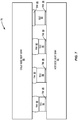
- FIG. 7 illustrates another embodiment of a heat exchanger 78 that reduces thermal interface resistance.
- the heat exchanger 78 includes a cold side heat sink 80, a hot side heat sink 82, and a number of TECs 84 disposed between the cold side heat sink 80 and the hot side heat sink 82.
- the TECs 84 have varying heights due to, for example, tolerances in a manufacturing process of the TECs 84.
- Hot sides of the TECs 84 are thermally and mechanically coupled to the hot side heat sink 82 via a thermal interface material 86, and cold sides of the TECs 84 are thermally and mechanically coupled to the cold side heat sink 80 via a thermal interface material 88.
- the hot sides of the TECs 84 dissipate both heat rejected by the cold side of the TECs 84 and heat generated by the TECs 84 themselves (i.e., heat generated due to power consumption of the TECs 84).
- the hot sides of the TECs 84 are referred to as critical sides of the TECs 84. Note, however, that for other applications of thermoelectric devices, the cold sides of the thermoelectric devices may be the critical sides.
- the hot sides of the TECs 84 are attached to the hot side heat sink 82 such that a minimum thickness of the thermal interface material 86 is achieved between each individual TEC 84 and the hot side heat sink 82. In this manner, the thermal interface resistance between each of the individual TECs 84 and the hot side heat sink 82 is minimized.
- the thermal interface material 86 can be any suitable thermal interface material such as, for example, thermal grease or paste, solder, thermally conductive pads, or the like.
- the hot side heat sink 82 (or alternatively a heat spreader(s) between the TECs 84 and the hot side heat sink 82) may include features that hold the TECs 84 in place.
- the cold sides of the TECs 84 are exposed during attachment of the TECs 84 to the hot side heat sink 82 and, as such, a force can be applied to each of the TECs 84 individually, which results in a consistent minimum bondline or thermal interface material thickness between the hot sides of the TECs 84 and the hot side heat sink 82 that is dependent only on the flatness of surface of the hot side heat sink 82, the flatness of the hot sides of the TECs 84, and the material properties of the thermal interface material 86.
- the bondline or thickness of the thermal interface material 88 is a function of all of the aforementioned parameters as well as the height variations of the TECs 84. As such, the thickness of the thermal interface material 88 will be greater for shorter TECs 84 than for taller TECs 84, as illustrated. In one embodiment, the thermal interface material 88 has a higher thermal conductivity than the thermal interface material 86 in order to at least partially offset the increased thickness of the thermal interface material 88 with respect to at least some of the TECs 84.
- the thickness of the thermal interface material between a TEC and a heat sink is preferably as thin as possible in order to minimize thermal interface resistance. Minimization of the thickness of the thermal interface material between a TEC and a heat sink can be achieved, at least in part, by ensuring that the heat sink is not tilted relative to the TEC. With a small TEC disposed between much larger heat sinks, this can be a mechanical challenge. Typically, this would require elaborate and potentially expensive mechanical structures to ensure parallel surfaces throughout the structure with sufficient force to achieve minimum thermal interface material thickness.
- Figure 8 illustrates a heat exchanger 90 that minimizes thermal interface resistance between a TEC and corresponding heat sinks according to another embodiment of the present disclosure.
- the heat exchanger 90 includes a cold side heat sink 92, a hot side heat sink 94, and a TEC 96 disposed between the cold side heat sink 92 and the hot side heat sink 94.
- the heat exchanger 90 also includes a separate pedestal 98 that provides desired planarity and heat spreading. Note that the pedestal 98 may be desired in applications where, for example, a thickness of an insulation between the cold side and the hot side heat sinks 92 and 94 is greater than a thickness of the TEC 96.
- the hot side of the TEC 96 is thermally and mechanically coupled to the hot side heat sink 94 via a thermal interface material 100
- the cold side of the TEC 96 is thermally and mechanically coupled to the pedestal 98 via a thermal interface material 102
- the pedestal 98 is thermally and mechanically coupled to the cold side heat sink 92 via a thermal interface material 104.
- the thermal interface materials 100, 102, and 104 may be any suitable thermal interface material.
- the thermal interface materials 100, 102, and 104 may be the same thermal interface material or, alternatively, some or all of the thermal interface materials 100, 102, and 104 may be different thermal interface materials.
- the pedestal 98 is preferably between the TEC 96 and the cold side heat sink 92 as illustrated.
- a cross-sectional area of the pedestal 98 is closer to a cross-sectional area of the TEC 96 than that of the cold side heat sink 92, which in turn makes it much easier to achieve parallelism (e.g., the pedestal 98 is much easier to handle than a combined heat sink and pedestal and therefore can be more easily, accurately, and precisely placed to achieve the desired planarity).
- the pedestal 98 could be such that the surface of the pedestal 98 that is in thermal contact with the TEC 96 is smaller than the surface of the pedestal 98 that is in thermal contact with the cold side heat sink 92.
- the pedestal 98 may be in the shape of an upside down frustum of, for instance, a cone or a pyramid.
- the pedestal 98 can be formed of any suitable high conductivity material.
- the pedestal 98 can be formed of copper, and the cold side heat sink 92 can be formed of aluminum.
- the pedestal 98 and the interfaces between the pedestal 98 and the TEC 96 and the cold side heat sink 92 can be optimized to improve heat spreading.
- dimensions of the pedestal 98 at the interface to the TEC 96 are the same as or substantially the same as those of the TEC 96, and the dimensions of the pedestal 98 at the interface to the cold side heat sink 92 are larger.
Claims (18)
- Thermoelektrisches Wärmetauscherbauteil (14), das Folgendes umfasst:eine Leiterplatte (36);eine Vielzahl von an der Leiterplatte befestigten thermoelektrischen Vorrichtungen (40), wobei zwei oder mehr der Vielzahl von thermoelektrischen Vorrichtungen unterschiedliche Höhen relativ zu der Leiterplatte aufweisen;einen Wärmeverteilerdeckel (46, 58) über der Vielzahl von thermoelektrischen Vorrichtungen; undein Wärmeleitmaterial (72, 70) zwischen der Vielzahl von thermoelektrischen Vorrichtungen und dem Wärmeverteilerdeckel;dadurch gekennzeichnet, dass der Wärmeverteilerdeckel entsprechend den jeweiligen Höhen der Vielzahl der thermoelektrischen Vorrichtungen orientiert ist, sodass eine Dicke des Wärmeleitmaterials und somit ein Wärmeschnittstellenwiderstand für die Vielzahl von thermoelektrischen Vorrichtungen minimiert wird.
- Thermoelektrisches Wärmetauscherbauteil nach Anspruch 1, wobei:die Vielzahl von thermoelektrischen Vorrichtungen (40) an einer ersten Oberfläche der Leiterplatte angebracht sind und eine der ersten Oberfläche der Leiterplatte gegenüberliegende erste Oberfläche und eine der ersten Oberfläche gegenüberliegende zweite Oberfläche umfassen;die zwei oder mehr der Vielzahl von thermoelektrischen Vorrichtungen unterschiedliche Höhen relativ zu der ersten Oberfläche der Leiterplatte aufweisen;sich der Wärmeverteilerdeckel (58) auf den ersten Oberflächen der Vielzahl von thermoelektrischen Vorrichtungen gegenüber von der ersten Oberfläche der Leiterplatte befindet; unddas Wärmeleitmaterial (72) sich zwischen den ersten Oberflächen der Vielzahl von thermoelektrischen Vorrichtungen und dem Wärmeverteilerdeckel befindet;
- Thermoelektrischer Wärmetauscher nach Anspruch 2, der weiter Folgendes umfasst:einen zweiten Wärmeverteilerdeckel (46) auf den zweiten Oberflächen der Vielzahl von thermoelektrischen Vorrichtungen, die an einer zweiten Oberfläche der Leiterplatte durch ein oder mehrere Löcher (38) durch die Leiterplatte freigelegt sind; undein zweites Wärmeleitmaterial (70) zwischen der Vielzahl von thermoelektrischen Vorrichtungen und dem zweiten Wärmeverteilerdeckel;wobei der zweite Wärmeverteilerdeckel derart orientiert ist, dass eine Dicke des zweiten Wärmeleitmaterials und somit ein Wärmeschnittstellenwiderstand für die Vielzahl von thermoelektrischen Vorrichtungen minimiert ist.
- Thermoelektrisches Wärmetauscherbauteil nach Anspruch 2, wobei der Wärmeverteilerdeckel (58) Folgendes umfasst:einen Körper (60); undeine Vielzahl von Sockeln (62) gleicher Höhen, die sich von dem Körper in Richtung der ersten Oberflächen der Vielzahl von thermoelektrischen Vorrichtungen erstrecken, sodass jeder Sockel der Vielzahl von Sockeln auf eine entsprechende der Vielzahl von thermoelektrischen Vorrichtungen ausgerichtet ist;wobei sich das Wärmeleitmaterial (72) zwischen einer Oberfläche jedes Sockels der Vielzahl von Sockeln und der ersten Oberfläche der entsprechenden einen der Vielzahl von thermoelektrischen Vorrichtungen befindet und die Orientierung des Wärmeverteilerdeckels (58) derart ist, dass die Dicke des Wärmeleitmaterials zwischen jedem Sockel der Vielzahl von Sockeln und der ersten Oberfläche der entsprechenden einen der Vielzahl von thermoelektrischen Vorrichtungen für die Vielzahl von thermoelektrischen Vorrichtungen minimiert ist.
- Thermoelektrisches Wärmetauscherbauteil nach Anspruch 1, wobei:die Vielzahl von thermoelektrischen Vorrichtungen an einer ersten Oberfläche der Leiterplatte befestigt sind und eine der ersten Oberfläche der Leiterplatte gegenüberliegende erste Oberfläche und eine der ersten Oberfläche gegenüberliegende zweite Oberfläche umfassen;sich der Wärmeverteilerdeckel (46) über den ersten Oberflächen der Vielzahl von thermoelektrischen Vorrichtungen, die an einer zweiten Oberfläche der Leiterplatte durch ein oder mehrere Löcher (38) durch die Leiterplatte freigelegt sind, befindet;die zwei oder mehr der Vielzahl von thermoelektrischen Vorrichtungen unterschiedliche Höhen relativ zu der zweiten Oberfläche der Leiterplatte aufweisen; undsich das Wärmeleitmaterial (70) zwischen den Oberflächen der Vielzahl von thermoelektrischen Vorrichtungen und dem Wärmeverteilerdeckel befindet;
- Thermoelektrisches Wärmetauscherbauteil nach Anspruch 5, wobei der Wärmeverteilerdeckel Folgendes umfasst:einen Körper (48); undeine Vielzahl von Sockeln (50) gleicher Höhen, die sich von dem Körper in Richtung der ersten Oberflächen der Vielzahl von thermoelektrischen Vorrichtungen erstrecken, sodass jeder Sockel der Vielzahl von Sockeln auf eine entsprechende der Vielzahl von thermoelektrischen Vorrichtungen ausgerichtet ist;wobei sich das Wärmeleitmaterial (70) zwischen jedem Sockel der Vielzahl von Sockeln und der ersten Oberfläche der entsprechenden einen der Vielzahl von thermoelektrischen Vorrichtungen befindet und der Wärmeverteilerdeckel derart orientiert ist, dass die Dicke des Wärmeleitmaterials zwischen jedem Sockel der Vielzahl von Sockeln und der ersten Oberfläche der entsprechenden einen der Vielzahl von thermoelektrischen Vorrichtungen und somit ein Wärmeschnittstellenwiderstand für die Vielzahl von thermoelektrischen Vorrichtungen minimiert ist.
- Thermoelektrisches Wärmetauscherbauteil nach Anspruch 4 oder 6, wobei es sich bei dem Wärmeleitmaterial um eines einer Gruppe handelt, die aus Folgendem besteht: Lot und Thermofett.
- Thermoelektrisches Wärmetauscherbauteil nach Anspruch 4 oder 6, wobei es sich bei jedem Sockel der Vielzahl von Sockeln um einen der Folgenden handelt: ein Parallelepiped; oder einen Kegelstumpf.
- Thermoelektrisches Wärmetauscherbauteil nach Anspruch 4 oder 6, wobei ein Flächeninhalt einer Oberfläche jedes Sockels der Vielzahl von Sockeln in einem Bereich von und einschließlich 1 bis 10 Prozent kleiner ist als ein Flächeninhalt der ersten Oberfläche der entsprechenden einen der Vielzahl von thermoelektrischen Vorrichtungen.
- Thermoelektrisches Wärmetauscherbauteil nach Anspruch 4 oder 6, wobei der Wärmeverteilerdeckel weiter eine Lippe (52, 64) umfasst, die sich von dem Körper des Wärmeverteilerdeckels um einen Umfang des Wärmeverteilerdeckels herum erstreckt.
- Thermoelektrisches Wärmetauscherbauteil nach Anspruch 10, wobei eine Höhe der Lippe relativ zu dem Körper des Wärmeverteilerdeckels derart ist, dass für eine beliebige Kombination von Höhen der Vielzahl von thermoelektrischen Vorrichtungen innerhalb eines vordefinierten Toleranzbereichs mindestens ein vordefinierter Mindestzwischenraum zwischen der Lippe des Wärmeverteilerdeckels und der ersten oder der zweiten Oberfläche der Leiterplatte aufrechterhalten wird, wobei der mindestens eine vordefinierte Mindestzwischenraum größer als null ist.
- Thermoelektrisches Wärmetauscherbauteil nach Anspruch 11, weiter umfassend ein Befestigungsmaterial (74, 76), das den mindestens einen vordefinierten Mindestzwischenraum zwischen der Lippe des Wärmeverteilerdeckels und der ersten oder der zweiten Oberfläche der Leiterplatte um den Umfang des Wärmeverteilerdeckels herum ausfüllt.
- Thermoelektrisches Wärmetauscherbauteil nach Anspruch 12, wobei die Luppe des Wärmeverteilerdeckels und das Befestigungsmaterial auf den Wärmeverteilerdeckel ausgeübte Kraft absorbieren, um die Vielzahl von thermoelektrischen Vorrichtungen zu schützen.
- Thermoelektrisches Wärmetauscherbauteil nach Anspruch 12, wobei es sich bei dem Befestigungsmaterial um ein Epoxid handelt.
- Thermoelektrisches Wärmetauscherbauteil nach Anspruch 12, weiter umfassend einen Wärmeisolatorvorformling (54, 66) mit einem Loch (56, 68) mit Abmessungen, die Abmessungen des Wärmeverteilerdeckels (46, 58) entsprechen, wobei der Wärmeisolatorvorformling derart über der Leiterplatte positioniert ist, dass der Wärmeverteilerdeckel durch das Loch in dem Wärmeisolatorvorformling gelangt.
- Verfahren zum Herstellen eines thermoelektrischen Wärmetauscherbauteils, das Folgendes umfasst:Befestigen einer Vielzahl von thermoelektrischen Vorrichtungen an einer Leiterplatte, wobei zwei oder mehr der Vielzahl von thermoelektrischen Vorrichtungen unterschiedliche Höhen relativ zu der Leiterplatte aufweisen;Aufbringen eines Wärmeleitmaterials auf mindestens eines einer Gruppe, die aus Folgendem besteht: der Vielzahl von thermoelektrischen Vorrichtungen und einem Wärmeverteilerdeckel;Positionieren des Wärmeverteilerdeckels über die Vielzahl von thermoelektrischen Vorrichtungen; undAusüben einer Kugelspitzenkraft auf den Wärmeverteilerdeckel, sodass sich der Wärmeverteilerdeckel unter der Kugelspitzenkraft unter einer Orientierung entsprechend den jeweiligen Höhen der Vielzahl der thermoelektrischen Vorrichtungen setzt, bei der eine Dicke des Wärmeleitmaterials für die Vielzahl von thermoelektrischen Vorrichtungen minimiert ist.
- Verfahren nach Anspruch 16, weiter umfassend, während die Kugelspitzenkraft weiterhin auf den Wärmeverteilerdeckel ausgeübt wird, das Ausfüllen eines Zwischenraums zwischen einer Lippe des Wärmeverteilerdeckels und der Leiterplatte mit einem Befestigungsmaterial, um dadurch den Wärmeverteilerdeckel an der Leiterplatte zu befestigen.
- Verfahren nach Anspruch 17, wobei der Wärmeverteilerdeckel einen Körper und eine Vielzahl von Sockeln mit gleichen Höhen, die sich von dem Körper in Richtung von Oberflächen der Vielzahl von thermoelektrischen Vorrichtungen erstrecken, umfasst, sodass jeder Sockel der Vielzahl von Sockeln auf eine entsprechende der Vielzahl von thermoelektrischen Vorrichtungen ausgerichtet ist, und:das Aufbringen des Wärmeleitmaterials das Aufbringen des Wärmeleitmaterials auf mindestens eines eine Gruppe umfasst, die aus Folgendem besteht: der Vielzahl von thermoelektrischen Vorrichtungen und der Vielzahl von Sockeln des Wärmeverteilerdeckels;das Positionieren des Wärmeverteilerdeckels das derartige Positionieren des Wärmeverteilerdeckels umfasst, dass jeder Sockel der Vielzahl von Sockeln des Wärmeverteilerdeckels auf eine entsprechende der Vielzahl von thermoelektrischen Vorrichtungen ausgerichtet ist; unddas Ausüben der Kugelspitzenkraft das derartige Ausüben der Kugelspitzenkraft auf den Wärmeverteilerdeckel umfasst, dass sich der Wärmeverteilerdeckel in einer Orientierung setzt, in der eine Dicke des Wärmeleitmaterials zwischen jedem Sockel der Vielzahl von Sockeln und der entsprechenden einen der Vielzahl von thermoelektrischen Vorrichtungen für die Vielzahl von thermoelektrischen Vorrichtungen minimiert ist.
Applications Claiming Priority (3)
| Application Number | Priority Date | Filing Date | Title |
|---|---|---|---|
| US201261643625P | 2012-05-07 | 2012-05-07 | |
| US201261643622P | 2012-05-07 | 2012-05-07 | |
| PCT/US2013/039945 WO2013169774A2 (en) | 2012-05-07 | 2013-05-07 | Thermoelectric heat exchanger component including protective heat spreading lid and optimal thermal interface resistance |
Publications (2)
| Publication Number | Publication Date |
|---|---|
| EP2848101A2 EP2848101A2 (de) | 2015-03-18 |
| EP2848101B1 true EP2848101B1 (de) | 2019-04-10 |
Family
ID=48485478
Family Applications (1)
| Application Number | Title | Priority Date | Filing Date |
|---|---|---|---|
| EP13724983.5A Active EP2848101B1 (de) | 2012-05-07 | 2013-05-07 | Thermoelektrische wärmetauscherkomponente mit wärmeverteilungsschutzklappe und optimalem thermischem grenzflächenwiderstand |
Country Status (6)
| Country | Link |
|---|---|
| US (1) | US8893513B2 (de) |
| EP (1) | EP2848101B1 (de) |
| JP (1) | JP6403664B2 (de) |
| KR (1) | KR102023228B1 (de) |
| CN (1) | CN104509220B (de) |
| WO (1) | WO2013169774A2 (de) |
Families Citing this family (48)
| Publication number | Priority date | Publication date | Assignee | Title |
|---|---|---|---|---|
| US20130291555A1 (en) | 2012-05-07 | 2013-11-07 | Phononic Devices, Inc. | Thermoelectric refrigeration system control scheme for high efficiency performance |
| US20140352325A1 (en) * | 2013-06-03 | 2014-12-04 | Wendell Brown | Electronic coldpack and method of use |
| GB201310040D0 (en) * | 2013-06-05 | 2013-07-17 | Mars Inc | Cool storage cabinet with improved efficiency |
| PL3063798T3 (pl) * | 2013-10-28 | 2017-11-30 | Phononic Devices, Inc. | Termoelektryczna pompa ciepła ze strukturą otoczenia i przekładki (SAS) |
| KR102252584B1 (ko) | 2014-02-14 | 2021-05-14 | 젠썸 인코포레이티드 | 전도식 대류식 기온 제어 조립체 |
| CN104930890B (zh) * | 2014-03-19 | 2017-01-18 | 海尔集团公司 | 一种热交换器及半导体酒柜 |
| US10042402B2 (en) * | 2014-04-07 | 2018-08-07 | Google Llc | Systems and methods for thermal management of a chassis-coupled modular mobile electronic device |
| CN106416038B (zh) * | 2014-06-06 | 2019-12-31 | 弗诺尼克设备公司 | 用于驱动能源自觉应用中的热电冷却器的高效率功率转换架构 |
| US9593871B2 (en) | 2014-07-21 | 2017-03-14 | Phononic Devices, Inc. | Systems and methods for operating a thermoelectric module to increase efficiency |
| US10458683B2 (en) | 2014-07-21 | 2019-10-29 | Phononic, Inc. | Systems and methods for mitigating heat rejection limitations of a thermoelectric module |
| CN106662379B (zh) * | 2014-07-21 | 2020-09-08 | 弗诺尼克设备公司 | 用于减轻热电模块的排热限制的系统和方法 |
| US11639816B2 (en) | 2014-11-14 | 2023-05-02 | Gentherm Incorporated | Heating and cooling technologies including temperature regulating pad wrap and technologies with liquid system |
| WO2016077843A1 (en) | 2014-11-14 | 2016-05-19 | Cauchy Charles J | Heating and cooling technologies |
| US11857004B2 (en) | 2014-11-14 | 2024-01-02 | Gentherm Incorporated | Heating and cooling technologies |
| CN105716454B (zh) * | 2014-12-01 | 2019-05-31 | 青岛海尔特种电冰柜有限公司 | 热管散热式热交换装置的组装方法 |
| CN105716452B (zh) * | 2014-12-01 | 2019-03-05 | 青岛海尔特种电冰柜有限公司 | 热交换装置及半导体制冷设备 |
| CN105716317B (zh) * | 2014-12-01 | 2019-03-05 | 青岛海尔特种电冰柜有限公司 | 散热装置及半导体制冷设备 |
| CN105627798B (zh) * | 2014-12-01 | 2018-12-18 | 青岛海尔特种电冰柜有限公司 | 热交换装置及半导体制冷设备 |
| CN105716318B (zh) * | 2014-12-01 | 2019-05-31 | 青岛海尔特种电冰柜有限公司 | 热交换装置及半导体制冷设备 |
| CN105716339A (zh) * | 2014-12-01 | 2016-06-29 | 青岛海尔特种电冰柜有限公司 | 热管散热式热交换装置的制冷剂灌注方法 |
| CN105716456B (zh) * | 2014-12-01 | 2018-12-18 | 青岛海尔特种电冰柜有限公司 | 热交换装置及半导体制冷设备 |
| CN104534781B (zh) * | 2014-12-15 | 2016-11-23 | 青岛海尔股份有限公司 | 冷端换热装置及半导体制冷冰箱 |
| CN104567175B (zh) * | 2014-12-15 | 2016-11-23 | 青岛海尔股份有限公司 | 半导体制冷冰箱 |
| CN104613804B (zh) * | 2014-12-15 | 2017-03-01 | 青岛海尔股份有限公司 | 弯折管件及具有该弯折管件的半导体制冷冰箱 |
| DE102015220759A1 (de) * | 2015-10-23 | 2017-04-27 | Mahle International Gmbh | Wärmeübertrager, insbesondere thermoelektrische Wärmepumpe, zum Temperieren einer Batterie |
| US10845375B2 (en) * | 2016-02-19 | 2020-11-24 | Agjunction Llc | Thermal stabilization of inertial measurement units |
| US20170299237A1 (en) * | 2016-04-17 | 2017-10-19 | Andrew Xianyi Huang | Solar-powered system |
| KR101827120B1 (ko) * | 2016-05-30 | 2018-02-07 | 현대자동차주식회사 | 열전모듈용 하우징 |
| CN109312942B (zh) | 2016-06-20 | 2021-03-02 | 弗诺尼克公司 | 用于微气候控制的冷却风扇 |
| US10260819B2 (en) * | 2016-07-26 | 2019-04-16 | Tokitae Llc | Thermosiphons for use with temperature-regulated storage devices |
| CN106159377A (zh) * | 2016-08-26 | 2016-11-23 | 无锡恩吉威新能源有限公司 | 一种电动汽车动力电池温度控制系统 |
| US20180123013A1 (en) | 2016-10-31 | 2018-05-03 | Phononic Devices, Inc. | Metal core thermoelectric device |
| JP2020511792A (ja) * | 2017-03-10 | 2020-04-16 | フォノニック インコーポレイテッド | 熱電モジュールを有する複数プリントされた回路基板を使用した熱電ヒートポンプカスケード |
| JP7208970B2 (ja) | 2017-04-03 | 2023-01-19 | エコディスト,インク. | 大規模独立型チラー、オールインワンロータリ蒸発器及びそれに関連する方法 |
| JP6838504B2 (ja) * | 2017-06-16 | 2021-03-03 | 富士電機株式会社 | 半導体装置および半導体回路装置 |
| USD903727S1 (en) | 2018-02-19 | 2020-12-01 | Ecodyst, Inc. | Large scale chiller |
| JP2021522462A (ja) | 2018-04-19 | 2021-08-30 | エンバー テクノロジーズ, インコーポレイテッド | アクティブ温度制御を備えた携帯型冷却器 |
| GB2575661B (en) * | 2018-07-18 | 2020-08-19 | Flint Eng Ltd | Thermal management system |
| US11223004B2 (en) | 2018-07-30 | 2022-01-11 | Gentherm Incorporated | Thermoelectric device having a polymeric coating |
| CN113557399A (zh) | 2019-01-11 | 2021-10-26 | 恩伯技术公司 | 具有主动温度控制的便携式冷却器 |
| US11152557B2 (en) * | 2019-02-20 | 2021-10-19 | Gentherm Incorporated | Thermoelectric module with integrated printed circuit board |
| WO2020263710A1 (en) | 2019-06-25 | 2020-12-30 | Ember Technologies, Inc. | Portable cooler |
| US11162716B2 (en) | 2019-06-25 | 2021-11-02 | Ember Technologies, Inc. | Portable cooler |
| US11668508B2 (en) | 2019-06-25 | 2023-06-06 | Ember Technologies, Inc. | Portable cooler |
| US20210239336A1 (en) | 2020-02-04 | 2021-08-05 | Phononic, Inc. | Systems and methods for fluid-dynamic isolation of actively conditioned and return air flow in unconstrained environments |
| CN112178975A (zh) * | 2020-10-10 | 2021-01-05 | 蔚县中天电子股份合作公司 | 一种温差电致冷组件的调节结构 |
| WO2023114542A1 (en) | 2021-12-17 | 2023-06-22 | Phononic, Inc. | Countertop freezer |
| US11827075B1 (en) | 2022-07-26 | 2023-11-28 | Artyc PBC | Temperature-controlled shipping container |
Citations (4)
| Publication number | Priority date | Publication date | Assignee | Title |
|---|---|---|---|---|
| US6347521B1 (en) * | 1999-10-13 | 2002-02-19 | Komatsu Ltd | Temperature control device and method for manufacturing the same |
| US20060108097A1 (en) * | 2004-11-24 | 2006-05-25 | Hodes Marc S | Techniques for microchannel cooling |
| US20080041067A1 (en) * | 2006-06-28 | 2008-02-21 | Denso Corporation | Thermoelectric conversion device and manufacture method of the same |
| JP2009206113A (ja) * | 2008-02-26 | 2009-09-10 | Aisin Seiki Co Ltd | 熱電モジュール、熱電モジュールを用いた熱電装置及び熱電モジュールの製造方法 |
Family Cites Families (348)
| Publication number | Priority date | Publication date | Assignee | Title |
|---|---|---|---|---|
| US2027057A (en) | 1933-01-05 | 1936-01-07 | Servel Inc | Refrigeration |
| US2947150A (en) | 1958-02-21 | 1960-08-02 | Whirlpool Co | Refrigerating apparatus having improved heat transferring means |
| US3100969A (en) | 1960-08-03 | 1963-08-20 | Thore M Elfving | Thermoelectric refrigeration |
| FR1310228A (de) | 1961-01-06 | 1963-03-06 | ||
| US3393127A (en) | 1966-01-06 | 1968-07-16 | Braun & Co C F | Thermosiphon deep pool reactor |
| US3532159A (en) | 1968-07-24 | 1970-10-06 | Trw Inc | High performance heat pipe |
| US3621906A (en) | 1969-09-02 | 1971-11-23 | Gen Motors Corp | Control system for heat pipes |
| US3821881A (en) | 1972-07-14 | 1974-07-02 | Mobile Metal Prod Inc | Refrigerator box with door mounted refrigeration unit |
| US4011104A (en) | 1973-10-05 | 1977-03-08 | Hughes Aircraft Company | Thermoelectric system |
| US5333677A (en) | 1974-04-02 | 1994-08-02 | Stephen Molivadas | Evacuated two-phase head-transfer systems |
| JPS5916192B2 (ja) | 1977-09-24 | 1984-04-13 | シャープ株式会社 | 枕等の冷却装置 |
| DE2830852C3 (de) | 1978-07-13 | 1981-04-02 | Siemens AG, 1000 Berlin und 8000 München | Kühleinrichtung für den Rotor einer elektrischen Maschine |
| US4213448A (en) | 1978-08-24 | 1980-07-22 | Hebert Raymond T | Thermosiphon solar space heating system with phase change materials |
| JPS5612997A (en) | 1979-07-11 | 1981-02-07 | Hitachi Ltd | Heat exchanger |
| US4306613A (en) | 1980-03-10 | 1981-12-22 | Christopher Nicholas S | Passive cooling system |
| US4357932A (en) | 1980-05-29 | 1982-11-09 | Creare Incorporated | Self pumped solar energy collection system |
| US4335578A (en) | 1980-05-30 | 1982-06-22 | Ford Aerospace & Communications Corporation | Solar power converter with pool boiling receiver and integral heat exchanger |
| JPS5928839B2 (ja) | 1980-09-01 | 1984-07-16 | 工業技術院長 | 蓄熱機能を有する熱サイフオン型ヒ−トパイプ |
| US6866092B1 (en) | 1981-02-19 | 2005-03-15 | Stephen Molivadas | Two-phase heat-transfer systems |
| US4393663A (en) | 1981-04-13 | 1983-07-19 | Gas Research Institute | Two-phase thermosyphon heater |
| US4366857A (en) | 1981-04-28 | 1983-01-04 | The United States Of America As Represented By The Secretary Of The Air Force | Magnetic two-phase thermosiphon |
| JPS57196089A (en) | 1981-05-29 | 1982-12-01 | Hitachi Ltd | Heat pipe |
| JPS57202494A (en) | 1981-06-05 | 1982-12-11 | Sanyo Electric Co Ltd | Heat accumulating equipment for air-conditioning utilizing solar heat |
| US4476922A (en) | 1981-10-26 | 1984-10-16 | Heilig Jr Glenn M | Forced bilateral thermosiphon loop |
| US4383414A (en) * | 1981-10-30 | 1983-05-17 | Bipol Ltd. | Peltier refrigeration construction |
| US4513732A (en) | 1981-11-10 | 1985-04-30 | Feldman Jr Karl T | Passive integral solar heat collector system |
| JPS58123091A (ja) | 1982-01-18 | 1983-07-22 | Furukawa Electric Co Ltd:The | 冷却装置 |
| JPS58174109A (ja) | 1982-04-07 | 1983-10-13 | Hitachi Ltd | 低沸点媒体利用の発電プラント |
| JPS58178191A (ja) | 1982-04-09 | 1983-10-19 | Matsushita Electric Ind Co Ltd | 蓄熱装置 |
| JPS58198648A (ja) | 1982-05-13 | 1983-11-18 | Matsushita Electric Ind Co Ltd | ル−プ型ヒ−トパイプ式太陽熱温水器 |
| US4474228A (en) | 1982-08-24 | 1984-10-02 | The United States Of America As Represented By The Secretary Of The Navy | Closed cycle vaporization cooling system for underwater vehicle inner-to-outer hull heat transfer |
| US4546608A (en) | 1982-09-29 | 1985-10-15 | Hitachi, Ltd. | Thermo-siphon type generator apparatus |
| US4498306A (en) | 1982-11-09 | 1985-02-12 | Lewis Tyree Jr | Refrigerated transport |
| US4545364A (en) | 1982-12-20 | 1985-10-08 | One Design, Inc. | Solar heating module |
| US4449377A (en) | 1983-03-14 | 1984-05-22 | Westinghouse Electric Corp. | Thermosyphon coil arrangement for heat pump outdoor unit |
| US4505261A (en) | 1983-12-19 | 1985-03-19 | Hunter Billy D | Modular passive solar heating system |
| US4607498A (en) | 1984-05-25 | 1986-08-26 | Dinh Company, Inc. | High efficiency air-conditioner/dehumidifier |
| JPS60253791A (ja) | 1984-05-30 | 1985-12-14 | Hitachi Zosen Corp | 熱エネルギ−回収方法 |
| JPS61142635A (ja) | 1984-12-17 | 1986-06-30 | Toshiba Corp | 沸騰冷却促進装置 |
| JPS61228292A (ja) | 1985-03-30 | 1986-10-11 | Agency Of Ind Science & Technol | ヒ−トパイプ内蔵フインを設けた伝熱管 |
| JPS6241531A (ja) | 1985-08-16 | 1987-02-23 | Nippon Alum Mfg Co Ltd:The | 天井空調装置 |
| US4833567A (en) | 1986-05-30 | 1989-05-23 | Digital Equipment Corporation | Integral heat pipe module |
| JPS62284147A (ja) | 1986-06-03 | 1987-12-10 | Matsushita Electric Ind Co Ltd | ヒ−トポンプ給湯機 |
| US4687048A (en) | 1986-06-18 | 1987-08-18 | The United States Of America As Represented By The Administrator Of The National Aeronautics And Space Administration | Monogroove cold plate |
| JPS63118546A (ja) | 1986-11-05 | 1988-05-23 | Takenaka Komuten Co Ltd | ビル空調システム |
| US4700771A (en) | 1987-01-13 | 1987-10-20 | Air Products And Chemicals, Inc. | Multi-zone boiling process and apparatus |
| JPS62294897A (ja) | 1987-01-22 | 1987-12-22 | Fujikura Ltd | 蓄熱式熱交換器 |
| US4848445A (en) | 1987-10-28 | 1989-07-18 | Allied-Signal Inc. | Heat transfer apparatus and method |
| US4810460A (en) | 1988-02-22 | 1989-03-07 | General Electric Company | Nuclear boiling water reactor upper plenum with lateral throughpipes |
| US4842050A (en) | 1988-12-22 | 1989-06-27 | Allied-Signal Inc. | Heat transfer apparatus and method |
| US5628205A (en) | 1989-03-08 | 1997-05-13 | Rocky Research | Refrigerators/freezers incorporating solid-vapor sorption reactors capable of high reaction rates |
| US5477706A (en) | 1991-11-19 | 1995-12-26 | Rocky Research | Heat transfer apparatus and methods for solid-vapor sorption systems |
| US5598721A (en) | 1989-03-08 | 1997-02-04 | Rocky Research | Heating and air conditioning systems incorporating solid-vapor sorption reactors capable of high reaction rates |
| US5069274A (en) | 1989-12-22 | 1991-12-03 | Grumman Aerospace Corporation | Spacecraft radiator system |
| US5000252A (en) | 1990-02-22 | 1991-03-19 | Wright State University | Thermal energy storage system |
| EP0484034A1 (de) | 1990-10-31 | 1992-05-06 | Hewlett-Packard Company | Thermisches Tintenstrahldruckgerät mit Phasenumwandlungskühlung |
| JPH04174269A (ja) | 1990-11-05 | 1992-06-22 | Toshiba Corp | 電子冷蔵庫 |
| US5195575A (en) | 1991-04-09 | 1993-03-23 | Roger Wylie | Passive three-phase heat tube for the protection of apparatus from exceeding maximum or minimum safe working temperatures |
| US5161090A (en) | 1991-12-13 | 1992-11-03 | Hewlett-Packard Company | Heat pipe-electrical interconnect integration for chip modules |
| US5190098A (en) | 1992-04-03 | 1993-03-02 | Long Erwin L | Thermosyphon with evaporator having rising and falling sections |
| JP3451107B2 (ja) * | 1992-10-05 | 2003-09-29 | 株式会社エコ・トゥエンティーワン | 電子冷却装置 |
| JP3323568B2 (ja) | 1993-01-11 | 2002-09-09 | 株式会社神戸製鋼所 | プレートフィン熱交換器内蔵型の多段サーモサイホン |
| US5384051A (en) | 1993-02-05 | 1995-01-24 | Mcginness; Thomas G. | Supercritical oxidation reactor |
| JPH06294561A (ja) * | 1993-02-10 | 1994-10-21 | Matsushita Electric Works Ltd | 電子加熱冷却装置 |
| FR2702831B1 (fr) | 1993-03-17 | 1995-05-24 | Faudat | Procédé et dispositif de refroidissement de l'enceinte d'un échangeur thermique. |
| DE69420404T2 (de) | 1993-05-11 | 2000-02-10 | Rocky Research | Wärmeübertragungsvorrichtung und verfahren für feststoff-dampf-sorptionsanlagen |
| US5355678A (en) * | 1993-05-19 | 1994-10-18 | Shlomo Beitner | Thermoelectric element mounting apparatus |
| US5408847A (en) | 1993-05-26 | 1995-04-25 | Erickson; Donald C. | Rotary solid sorption heat pump with embedded thermosyphons |
| US5309725A (en) | 1993-07-06 | 1994-05-10 | Cayce James L | System and method for high-efficiency air cooling and dehumidification |
| US5596981A (en) | 1993-07-19 | 1997-01-28 | Soucy; Paul B. | Solar device and method for assembly |
| JP3273669B2 (ja) | 1993-07-23 | 2002-04-08 | 株式会社ワコム | 位置検出装置 |
| US5458189A (en) | 1993-09-10 | 1995-10-17 | Aavid Laboratories | Two-phase component cooler |
| US5704416A (en) | 1993-09-10 | 1998-01-06 | Aavid Laboratories, Inc. | Two phase component cooler |
| US5406805A (en) | 1993-11-12 | 1995-04-18 | University Of Maryland | Tandem refrigeration system |
| US5386701A (en) | 1994-02-03 | 1995-02-07 | Cao; Yiding | Human body cooling suit with heat pipe transfer |
| US5456081A (en) * | 1994-04-01 | 1995-10-10 | International Business Machines Corporation | Thermoelectric cooling assembly with optimized fin structure for improved thermal performance and manufacturability |
| US5411077A (en) | 1994-04-11 | 1995-05-02 | Minnesota Mining And Manufacturing Company | Flexible thermal transfer apparatus for cooling electronic components |
| US5647429A (en) | 1994-06-16 | 1997-07-15 | Oktay; Sevgin | Coupled, flux transformer heat pipes |
| US5864466A (en) | 1994-07-19 | 1999-01-26 | Remsburg; Ralph | Thermosyphon-powered jet-impingement cooling device |
| US5551244A (en) | 1994-11-18 | 1996-09-03 | Martin Marietta Corporation | Hybrid thermoelectric/Joule-Thomson cryostat for cooling detectors |
| JPH08306832A (ja) * | 1995-05-01 | 1996-11-22 | Mitsubishi Electric Corp | 冷却装置 |
| JPH08316532A (ja) * | 1995-05-19 | 1996-11-29 | Hitachi Chem Co Ltd | 冷却ユニット構造 |
| DE19521344C5 (de) | 1995-06-12 | 2006-03-16 | Fraunhofer-Gesellschaft zur Förderung der angewandten Forschung e.V. | Verwendung von Plasmapolymer-Hartstoff-Schichtenfolgen als Funktionsschichten in Stofftransport - oder Wärmetauschersystemen |
| US5548971A (en) | 1995-06-14 | 1996-08-27 | Rocky Research | Method for use of liquid/vapor ammonia absorption systems in unitary HVAC systems |
| US5770903A (en) | 1995-06-20 | 1998-06-23 | Sundstrand Corporation | Reflux-cooled electro-mechanical device |
| US5587880A (en) | 1995-06-28 | 1996-12-24 | Aavid Laboratories, Inc. | Computer cooling system operable under the force of gravity in first orientation and against the force of gravity in second orientation |
| DE69615946T2 (de) | 1995-07-14 | 2002-04-04 | Actronics Kk | Verfahren zur Herstellung von Tunnelplatten-Wärmerohren |
| US5622057A (en) | 1995-08-30 | 1997-04-22 | Carrier Corporation | High latent refrigerant control circuit for air conditioning system |
| US5655598A (en) | 1995-09-19 | 1997-08-12 | Garriss; John Ellsworth | Apparatus and method for natural heat transfer between mediums having different temperatures |
| JPH0992890A (ja) * | 1995-09-25 | 1997-04-04 | Matsushita Electric Works Ltd | 熱電気変換装置 |
| US6014968A (en) | 1995-09-26 | 2000-01-18 | Alam Hassan | Tubular heating-pipe solar water-heating-system with integral tank |
| EP0855006B1 (de) | 1995-10-13 | 1999-09-01 | Société Generfeu | Heizungsanlage für ein gebäude mit wärmerohr |
| US5737923A (en) | 1995-10-17 | 1998-04-14 | Marlow Industries, Inc. | Thermoelectric device with evaporating/condensing heat exchanger |
| US5579830A (en) | 1995-11-28 | 1996-12-03 | Hudson Products Corporation | Passive cooling of enclosures using heat pipes |
| JP3557760B2 (ja) * | 1995-12-18 | 2004-08-25 | アイシン精機株式会社 | 熱電変換装置 |
| JP3312169B2 (ja) * | 1996-04-24 | 2002-08-05 | 文部科学省科学技術・学術政策局長 | 熱電発電モジュールの取り付け方法 |
| JP3241270B2 (ja) * | 1996-06-25 | 2001-12-25 | 日本政策投資銀行 | 熱電変換装置 |
| US6058712A (en) | 1996-07-12 | 2000-05-09 | Thermotek, Inc. | Hybrid air conditioning system and a method therefor |
| US6167948B1 (en) | 1996-11-18 | 2001-01-02 | Novel Concepts, Inc. | Thin, planar heat spreader |
| US6064572A (en) | 1996-11-27 | 2000-05-16 | Remsburg; Ralph | Thermosyphon-powered jet-impingement cooling device |
| JP3054098B2 (ja) | 1997-02-25 | 2000-06-19 | スガツネ工業株式会社 | ヒンジ |
| JP3918279B2 (ja) | 1997-02-28 | 2007-05-23 | アイシン精機株式会社 | 多段電子冷却装置及びその製造方法 |
| CA2255708A1 (en) | 1997-04-10 | 1998-10-15 | Paul Gerard Conway | Apparatus and method for operating a heat pipe panel assembly |
| JPH1163862A (ja) | 1997-08-22 | 1999-03-05 | Furukawa Electric Co Ltd:The | 板型ヒートパイプとそれを用いた冷却構造 |
| US6314741B1 (en) | 1997-08-25 | 2001-11-13 | Citizen Watch Co., Ltd. | Thermoelectric device |
| JPH11145380A (ja) * | 1997-11-06 | 1999-05-28 | Hitachi Ltd | 半導体スタック |
| US5931156A (en) | 1997-11-18 | 1999-08-03 | Industrial Technology Research Institute | Integral heat-pipe type solar collector |
| US6109044A (en) | 1998-01-26 | 2000-08-29 | International Environmental Corp. | Conditioned air fan coil unit |
| US5970719A (en) | 1998-03-02 | 1999-10-26 | Merritt; Thomas | Heating and cooling device |
| US6055157A (en) | 1998-04-06 | 2000-04-25 | Cray Research, Inc. | Large area, multi-device heat pipe for stacked MCM-based systems |
| JP3284966B2 (ja) * | 1998-04-14 | 2002-05-27 | ダイキン工業株式会社 | 冷熱源ユニット |
| ES2159218B1 (es) | 1998-05-14 | 2002-04-01 | Consejo Superior Investigacion | Refrigerador domestico con efecto peltier, acumuladores termicos y termosifones evaporativos. |
| US6019165A (en) | 1998-05-18 | 2000-02-01 | Batchelder; John Samuel | Heat exchange apparatus |
| US6021844A (en) | 1998-06-03 | 2000-02-08 | Batchelder; John Samuel | Heat exchange apparatus |
| US6097597A (en) | 1998-06-30 | 2000-08-01 | Mitsubishi Denki Kabushiki Kaisha | Thermo-siphon and manufacturing method of thermo-siphon and information processing apparatus |
| JP3580406B2 (ja) * | 1998-09-16 | 2004-10-20 | 日本電信電話株式会社 | 高温度熱電変換素子 |
| EP1003006A1 (de) | 1998-11-19 | 2000-05-24 | Franz Isella S.p.A. | Hybridsystem zur passiven Kühlung mittels Wärmeröhren |
| US6073888A (en) | 1998-12-02 | 2000-06-13 | Loral Space & Communications, Ltd. | Sequenced heat rejection for body stabilized geosynchronous satellites |
| US6161388A (en) | 1998-12-28 | 2000-12-19 | International Business Machines Corporation | Enhanced duty cycle design for micro thermoelectromechanical coolers |
| US6237682B1 (en) | 1999-04-30 | 2001-05-29 | Motorola, Inc. | Cooling module including a pressure relief mechanism |
| US6148905A (en) | 1999-04-30 | 2000-11-21 | Motorola, Inc. | Two-phase thermosyphon including air feed through slots |
| US6234242B1 (en) | 1999-04-30 | 2001-05-22 | Motorola, Inc. | Two-phase thermosyphon including a porous structural material having slots disposed therein |
| US6237223B1 (en) | 1999-05-06 | 2001-05-29 | Chip Coolers, Inc. | Method of forming a phase change heat sink |
| US6499777B1 (en) | 1999-05-11 | 2002-12-31 | Matrix Integrated Systems, Inc. | End-effector with integrated cooling mechanism |
| JP4223628B2 (ja) | 1999-05-20 | 2009-02-12 | ティーエス ヒートロニクス 株式会社 | 電子機器冷却装置 |
| KR100294317B1 (ko) | 1999-06-04 | 2001-06-15 | 이정현 | 초소형 냉각 장치 |
| US7069975B1 (en) | 1999-09-16 | 2006-07-04 | Raytheon Company | Method and apparatus for cooling with a phase change material and heat pipes |
| US6410982B1 (en) | 1999-11-12 | 2002-06-25 | Intel Corporation | Heatpipesink having integrated heat pipe and heat sink |
| US7310971B2 (en) | 2004-10-25 | 2007-12-25 | Conocophillips Company | LNG system employing optimized heat exchangers to provide liquid reflux stream |
| US20010023762A1 (en) | 2000-01-11 | 2001-09-27 | Sagal E. Mikhail | Heat pipe spreader construction |
| US6585039B2 (en) | 2000-02-01 | 2003-07-01 | Cool Options, Inc. | Composite overmolded heat pipe construction |
| CA2305647C (en) | 2000-04-20 | 2006-07-11 | Jacques Laliberte | Modular thermoelectric unit and cooling system using same |
| US6382309B1 (en) | 2000-05-16 | 2002-05-07 | Swales Aerospace | Loop heat pipe incorporating an evaporator having a wick that is liquid superheat tolerant and is resistant to back-conduction |
| JP2001330339A (ja) | 2000-05-19 | 2001-11-30 | Gac Corp | ペルチェ冷却ユニットおよび冷却装置 |
| JP2002013885A (ja) | 2000-06-28 | 2002-01-18 | Twinbird Corp | 冷凍機用サーモサイフォン |
| US7251889B2 (en) | 2000-06-30 | 2007-08-07 | Swales & Associates, Inc. | Manufacture of a heat transfer system |
| EP1305562B1 (de) | 2000-06-30 | 2006-03-08 | Swales Aerospace | Phasenregelung in einem kapillarverdampfer |
| US8047268B1 (en) | 2002-10-02 | 2011-11-01 | Alliant Techsystems Inc. | Two-phase heat transfer system and evaporators and condensers for use in heat transfer systems |
| US8109325B2 (en) | 2000-06-30 | 2012-02-07 | Alliant Techsystems Inc. | Heat transfer system |
| US7004240B1 (en) | 2002-06-24 | 2006-02-28 | Swales & Associates, Inc. | Heat transport system |
| US7708053B2 (en) | 2000-06-30 | 2010-05-04 | Alliant Techsystems Inc. | Heat transfer system |
| US8136580B2 (en) | 2000-06-30 | 2012-03-20 | Alliant Techsystems Inc. | Evaporator for a heat transfer system |
| US7549461B2 (en) | 2000-06-30 | 2009-06-23 | Alliant Techsystems Inc. | Thermal management system |
| US6294853B1 (en) | 2000-08-02 | 2001-09-25 | The United States Of America As Represented By The Secretary Of The Air Force | Cooling of electromechanical actuator with phase change material and thermosyphons containing working fluid |
| JP2002089990A (ja) * | 2000-09-19 | 2002-03-27 | Mitsubishi Electric Corp | 冷却装置 |
| US6345507B1 (en) * | 2000-09-29 | 2002-02-12 | Electrografics International Corporation | Compact thermoelectric cooling system |
| US6679316B1 (en) | 2000-10-02 | 2004-01-20 | The United States Of America As Represented By The Secretary Of The Air Force | Passive thermal spreader and method |
| DE10194457B4 (de) | 2000-10-03 | 2006-08-24 | Visteon Global Technologies, Inc., Dearborn | System und Verfahren zum Anbringen elektronischer Komponenten auf flexiblen Substraten |
| US6631624B1 (en) | 2000-11-10 | 2003-10-14 | Rocky Research | Phase-change heat transfer coupling for aqua-ammonia absorption systems |
| JP2002168547A (ja) | 2000-11-20 | 2002-06-14 | Global Cooling Bv | 熱サイホンによるcpu冷却装置 |
| KR100419318B1 (ko) | 2000-12-07 | 2004-02-19 | 한국전력공사 | 써모사이펀을 이용한 액체금속로의 잔열제거장치 |
| DE20105487U1 (de) | 2001-01-31 | 2001-10-18 | Digger Res And Man Corp | Kühlgerät mit mehreren Arbeitsmodi zur Optimierung der Effektivität. |
| US7556086B2 (en) | 2001-04-06 | 2009-07-07 | University Of Maryland, College Park | Orientation-independent thermosyphon heat spreader |
| US6657121B2 (en) | 2001-06-27 | 2003-12-02 | Thermal Corp. | Thermal management system and method for electronics system |
| US6536510B2 (en) | 2001-07-10 | 2003-03-25 | Thermal Corp. | Thermal bus for cabinets housing high power electronics equipment |
| US6388882B1 (en) | 2001-07-19 | 2002-05-14 | Thermal Corp. | Integrated thermal architecture for thermal management of high power electronics |
| JP2004537705A (ja) | 2001-07-20 | 2004-12-16 | エイ・エル・エム・エイ テクノロジー コーポレーション リミテッド | 熱交換器及び熱交換マニホールド |
| US6672373B2 (en) | 2001-08-27 | 2004-01-06 | Idalex Technologies, Inc. | Method of action of the pulsating heat pipe, its construction and the devices on its base |
| US6533029B1 (en) | 2001-09-04 | 2003-03-18 | Thermal Corp. | Non-inverted meniscus loop heat pipe/capillary pumped loop evaporator |
| US6828675B2 (en) | 2001-09-26 | 2004-12-07 | Modine Manufacturing Company | Modular cooling system and thermal bus for high power electronics cabinets |
| US6808011B2 (en) | 2001-09-26 | 2004-10-26 | Thermal.Corp. | Heat pipe system for cooling flywheel energy storage systems |
| US6942018B2 (en) | 2001-09-28 | 2005-09-13 | The Board Of Trustees Of The Leland Stanford Junior University | Electroosmotic microchannel cooling system |
| JP2002184918A (ja) * | 2001-10-01 | 2002-06-28 | Nec Corp | 温度制御ユニット |
| US20030075306A1 (en) | 2001-10-19 | 2003-04-24 | Jon Zuo | Thermal control layer in miniature LHP/CPL wicks |
| US6568857B1 (en) | 2001-11-08 | 2003-05-27 | The Torrington Company | Thrust bearing assembly |
| US6739138B2 (en) | 2001-11-26 | 2004-05-25 | Innovations Inc. | Thermoelectric modules and a heating and cooling apparatus incorporating same |
| US6642485B2 (en) | 2001-12-03 | 2003-11-04 | Visteon Global Technologies, Inc. | System and method for mounting electronic components onto flexible substrates |
| US6712258B2 (en) | 2001-12-13 | 2004-03-30 | International Business Machines Corporation | Integrated quantum cold point coolers |
| US6889753B2 (en) | 2001-12-19 | 2005-05-10 | Ts Heatronics Co., Ltd. | Capillary tube heat pipe and temperature controlling apparatus |
| US20030121515A1 (en) | 2001-12-28 | 2003-07-03 | Industrial Technology Research Institute | Counter - thermosyphon loop heat pipe solar collector |
| CN1195196C (zh) | 2002-01-10 | 2005-03-30 | 杨洪武 | 集成式热管及其换热方法 |
| US6745830B2 (en) | 2002-01-22 | 2004-06-08 | Khanh Dinh | Heat pipe loop with pump assistance |
| FR2835090B1 (fr) | 2002-01-23 | 2005-08-05 | Commissariat Energie Atomique | Installation d'entreposage de tres longue duree de produits emettant un flux thermique eleve |
| DE60225598D1 (en) | 2002-01-29 | 2008-04-24 | Ericsson Telefon Ab L M | Gehäusekühlung |
| JP2003244968A (ja) | 2002-02-15 | 2003-08-29 | Toshiba Corp | 車両用電力変換装置 |
| US20030159806A1 (en) | 2002-02-28 | 2003-08-28 | Sehmbey Maninder Singh | Flat-plate heat-pipe with lanced-offset fin wick |
| US6557354B1 (en) | 2002-04-04 | 2003-05-06 | International Business Machines Corporation | Thermoelectric-enhanced heat exchanger |
| JP4033699B2 (ja) | 2002-04-08 | 2008-01-16 | シャープ株式会社 | ループ型サーモサイホンおよびスターリング冷蔵庫 |
| DE60323832D1 (de) | 2002-05-21 | 2008-11-13 | Univ Duke | Batch-target und verfahren zur erzeugung eines radionuklids |
| JP2003343985A (ja) | 2002-05-27 | 2003-12-03 | Komatsu Electronics Inc | プレート状熱交換器 |
| FR2840394B1 (fr) | 2002-05-30 | 2004-08-27 | Cit Alcatel | Dispositif de transfert de chaleur pour satellite comprenant un evaporateur |
| US6527548B1 (en) * | 2002-06-20 | 2003-03-04 | Hi-Z Technology, Inc. | Self powered electric generating space heater |
| CN1281715C (zh) | 2002-07-03 | 2006-10-25 | 埃克森美孚化学专利公司 | 在热裂化应用中将雾流转换为环形流 |
| US6631755B1 (en) | 2002-07-17 | 2003-10-14 | Compal Electronics, Inc. | Thermal module with temporary heat storage |
| FR2843446B1 (fr) | 2002-08-07 | 2005-02-25 | Peugeot Citroen Automobiles Sa | Systeme de climatisation, notamment pour vehicule automobile |
| US6804117B2 (en) | 2002-08-14 | 2004-10-12 | Thermal Corp. | Thermal bus for electronics systems |
| DE10244428A1 (de) | 2002-09-24 | 2004-06-17 | Siemens Ag | Elektrische Maschine mit einer Kühleinrichtung |
| FR2845351B1 (fr) | 2002-10-03 | 2005-07-22 | Cit Alcatel | Architecture modulaire pour le controle thermique d'un vehicule spatial |
| JP2004140429A (ja) | 2002-10-15 | 2004-05-13 | Okano Electric Wire Co Ltd | 冷却電子カメラ |
| US6994151B2 (en) | 2002-10-22 | 2006-02-07 | Cooligy, Inc. | Vapor escape microchannel heat exchanger |
| FR2846195B1 (fr) | 2002-10-23 | 2005-01-21 | Gen Biscuit | Procede de fabrication d'un produit alimentaire a base de cereales, cuit dans un moule |
| US6771498B2 (en) | 2002-10-25 | 2004-08-03 | Thermal Corp. | Cooling system for hinged portable computing device |
| US6658857B1 (en) | 2003-02-20 | 2003-12-09 | Hatho M. George | Portable thermoelectric cooling and heating appliance device and method of using |
| JP4029748B2 (ja) | 2003-03-18 | 2008-01-09 | 富士電機リテイルシステムズ株式会社 | スターリング冷凍機の冷熱移送装置 |
| SE0301381D0 (sv) | 2003-05-12 | 2003-05-12 | Sapa Ab | Extruded heat sink with integrated thermosyphon |
| US7215541B2 (en) | 2003-07-11 | 2007-05-08 | Intel Corporation | Multi-stage low noise integrated object and system cooling solution |
| US6951114B2 (en) | 2003-07-15 | 2005-10-04 | Weatherford/Lamb, Inc. | Reliable outdoor instrument cooling system |
| WO2005008160A1 (ja) | 2003-07-23 | 2005-01-27 | Sharp Kabushiki Kaisha | ループ型サーモサイフォン、放熱システム、熱交換システムおよびスターリング冷却庫 |
| JP4488778B2 (ja) | 2003-07-25 | 2010-06-23 | 株式会社東芝 | 熱電変換装置 |
| US7013955B2 (en) | 2003-07-28 | 2006-03-21 | Thermal Corp. | Flexible loop thermosyphon |
| US6789610B1 (en) | 2003-08-28 | 2004-09-14 | Hewlett-Packard Development Company, L.P. | High performance cooling device with vapor chamber |
| US7013956B2 (en) | 2003-09-02 | 2006-03-21 | Thermal Corp. | Heat pipe evaporator with porous valve |
| WO2005024331A1 (ja) | 2003-09-02 | 2005-03-17 | Sharp Kabushiki Kaisha | ループ型サーモサイフォン、スターリング冷却庫ならびに冷却装置 |
| JP4714151B2 (ja) | 2003-10-15 | 2011-06-29 | アイス エナジー インコーポレーテッド | 冷却装置 |
| US7854129B2 (en) | 2003-10-15 | 2010-12-21 | Ice Energy, Inc. | Refrigeration apparatus |
| JP4623600B2 (ja) | 2003-10-15 | 2011-02-02 | アイス エナジー インコーポレーテッド | 冷媒を用いた高性能蓄熱冷却システム |
| EP1531384A3 (de) | 2003-11-14 | 2006-12-06 | LG Electronics Inc. | Kühlvorrichtung für tragbaren Rechner |
| JP2005172329A (ja) | 2003-12-10 | 2005-06-30 | Sharp Corp | 冷却庫 |
| US7032389B2 (en) | 2003-12-12 | 2006-04-25 | Thermoelectric Design, Llc | Thermoelectric heat pump with direct cold sink support |
| US7448222B2 (en) | 2003-12-15 | 2008-11-11 | Bormann Ronald M | Thermoelectric refrigeration system |
| JP2005183676A (ja) * | 2003-12-19 | 2005-07-07 | Matsushita Electric Ind Co Ltd | 電子冷却ユニット |
| JP2005195226A (ja) | 2004-01-06 | 2005-07-21 | Mitsubishi Electric Corp | ポンプレス水冷システム |
| JP4039380B2 (ja) | 2004-03-24 | 2008-01-30 | トヨタ自動車株式会社 | 内燃機関の空燃比制御装置 |
| US7231961B2 (en) | 2004-03-31 | 2007-06-19 | Belits Computer Systems, Inc. | Low-profile thermosyphon-based cooling system for computers and other electronic devices |
| US7958935B2 (en) | 2004-03-31 | 2011-06-14 | Belits Computer Systems, Inc. | Low-profile thermosyphon-based cooling system for computers and other electronic devices |
| JP2005315462A (ja) | 2004-04-27 | 2005-11-10 | Sanki Eng Co Ltd | 蓄熱式放射冷暖房パネル |
| US7509995B2 (en) | 2004-05-06 | 2009-03-31 | Delphi Technologies, Inc. | Heat dissipation element for cooling electronic devices |
| US7304842B2 (en) | 2004-06-14 | 2007-12-04 | Cray Inc. | Apparatuses and methods for cooling electronic devices in computer systems |
| US7266976B2 (en) | 2004-10-25 | 2007-09-11 | Conocophillips Company | Vertical heat exchanger configuration for LNG facility |
| US7212403B2 (en) | 2004-10-25 | 2007-05-01 | Rocky Research | Apparatus and method for cooling electronics and computer components with managed and prioritized directional air flow heat rejection |
| US20060088746A1 (en) | 2004-10-25 | 2006-04-27 | 3M Innovative Properties Company | Passive dual-phase cooling for fuel cell assemblies |
| US7051536B1 (en) * | 2004-11-12 | 2006-05-30 | Bio-Rad Laboratories, Inc. | Thermal cycler with protection from atmospheric moisture |
| US20060118969A1 (en) * | 2004-12-03 | 2006-06-08 | Taiwan Semiconductor Manufacturing Co., Ltd. | Flip chip ball grid array package assemblies and electronic devices with heat dissipation capability |
| US7642644B2 (en) | 2004-12-03 | 2010-01-05 | Mayo Foundation For Medical Education And Research | Packaging for high power integrated circuits |
| US7227749B2 (en) | 2004-12-07 | 2007-06-05 | Rocky Research | Thermal bus load control management for electronic systems |
| US7285802B2 (en) | 2004-12-21 | 2007-10-23 | 3M Innovative Properties Company | Illumination assembly and method of making same |
| US7266969B2 (en) | 2005-01-06 | 2007-09-11 | Ut-Batelle, Llc | Refrigerant directly cooled capacitors |
| US7506682B2 (en) | 2005-01-21 | 2009-03-24 | Delphi Technologies, Inc. | Liquid cooled thermosiphon for electronic components |
| US20060162903A1 (en) | 2005-01-21 | 2006-07-27 | Bhatti Mohinder S | Liquid cooled thermosiphon with flexible partition |
| US7077189B1 (en) | 2005-01-21 | 2006-07-18 | Delphi Technologies, Inc. | Liquid cooled thermosiphon with flexible coolant tubes |
| JP2006261221A (ja) * | 2005-03-15 | 2006-09-28 | Seiko Instruments Inc | 電子回路及び電子機器 |
| CA2614803C (en) | 2005-04-05 | 2015-08-25 | Tir Technology Lp | Electronic device package with an integrated evaporator |
| US7604040B2 (en) | 2005-06-15 | 2009-10-20 | Coolit Systems Inc. | Integrated liquid cooled heat sink for electronic components |
| WO2007000042A1 (en) | 2005-06-27 | 2007-01-04 | Fleming Mark A | Refrigerator or freezer with enhanced efficiency |
| CA2511034C (en) | 2005-06-29 | 2009-01-06 | Grit Industries Inc. | Heat exchange apparatus |
| CN100556216C (zh) | 2005-07-02 | 2009-10-28 | 富准精密工业(深圳)有限公司 | 导热模组 |
| JP2007035974A (ja) * | 2005-07-27 | 2007-02-08 | Aisin Seiki Co Ltd | 熱電変換装置 |
| EP1915580A4 (de) | 2005-07-28 | 2010-12-22 | Carrier Corp | Entfeuchtungsregelkreis für kühlsystem |
| JP4901350B2 (ja) * | 2005-08-02 | 2012-03-21 | 株式会社東芝 | 熱電変換装置及びその製造方法 |
| CN100585896C (zh) * | 2005-08-02 | 2010-01-27 | 株式会社东芝 | 热电装置及其制造方法 |
| JP2007093112A (ja) | 2005-08-31 | 2007-04-12 | Sanyo Electric Co Ltd | 冷却貯蔵庫 |
| US7212409B1 (en) | 2005-12-05 | 2007-05-01 | Hewlett-Packard Development Company, L.P. | Cam actuated cold plate |
| US20070227703A1 (en) | 2006-03-31 | 2007-10-04 | Bhatti Mohinder S | Evaporatively cooled thermosiphon |
| US20070227701A1 (en) | 2006-03-31 | 2007-10-04 | Bhatti Mohinder S | Thermosiphon with flexible boiler plate |
| US7556089B2 (en) | 2006-03-31 | 2009-07-07 | Coolit Systems, Inc. | Liquid cooled thermosiphon with condenser coil running in and out of liquid refrigerant |
| US20070246195A1 (en) | 2006-04-19 | 2007-10-25 | Bhatti Mohinder S | Orientation insensitive thermosiphon with squirrel cage configuration |
| US7424906B2 (en) | 2006-04-19 | 2008-09-16 | Delphi Technologies, Inc. | High performance thermosiphon with internally enhanced condensation |
| US20070246193A1 (en) | 2006-04-20 | 2007-10-25 | Bhatti Mohinder S | Orientation insensitive thermosiphon of v-configuration |
| US7406999B2 (en) | 2006-04-27 | 2008-08-05 | Delphi Technologies, Inc. | Capillary-assisted compact thermosiphon |
| US7520317B2 (en) | 2006-05-16 | 2009-04-21 | Delphi Technologies, Inc | Orientation insensitive compact thermosiphon with a remote auxiliary condenser |
| US8720530B2 (en) | 2006-05-17 | 2014-05-13 | The Boeing Company | Multi-layer wick in loop heat pipe |
| US7644753B2 (en) | 2006-05-23 | 2010-01-12 | Delphi Technologies, Inc. | Domed heat exchanger (porcupine) |
| US7665511B2 (en) | 2006-05-25 | 2010-02-23 | Delphi Technologies, Inc. | Orientation insensitive thermosiphon capable of operation in upside down position |
| US20080012436A1 (en) | 2006-07-13 | 2008-01-17 | Encap Technologies Inc. | Electromagnetic device with encapsulated heat transfer fluid confinement member |
| US20080013283A1 (en) | 2006-07-17 | 2008-01-17 | Gilbert Gary L | Mechanism for cooling electronic components |
| US7928348B2 (en) | 2006-07-19 | 2011-04-19 | Encap Technologies Inc. | Electromagnetic device with integrated fluid flow path |
| US7629716B2 (en) | 2006-07-19 | 2009-12-08 | Encap Technologies Inc. | Electromagnetic device with closed heat transfer system |
| US7566999B2 (en) | 2006-07-19 | 2009-07-28 | Encap Technologies Inc. | Electromagnetic device with composite structure heat transfer flow path |
| US7683509B2 (en) | 2006-07-19 | 2010-03-23 | Encap Technologies Inc. | Electromagnetic device with open, non-linear heat transfer system |
| DE602007003478D1 (de) | 2006-07-25 | 2010-01-07 | Shell Int Research | Verfahren und vorrichtung zum verdampfen eines flüssigkeitsstroms |
| US7861538B2 (en) | 2006-07-26 | 2011-01-04 | The Aerospace Corporation | Thermoelectric-based refrigerator apparatuses |
| JP2008034630A (ja) * | 2006-07-28 | 2008-02-14 | Toyota Motor Corp | 熱電発電モジュール |
| TWI301937B (en) * | 2006-07-31 | 2008-10-11 | Compal Electronics Inc | Thermal conducting medium protector |
| US7477516B2 (en) | 2006-08-17 | 2009-01-13 | Delphi Technologies, Inc. | Air cooled computer chip |
| US9091490B2 (en) | 2006-08-23 | 2015-07-28 | The United States Of America As Represented By The Administrator Of The National Aeronautics And Space Administration | Open loop heat pipe radiator having a free-piston for wiping condensed working fluid |
| ATE510337T1 (de) | 2006-08-25 | 2011-06-15 | Abb Research Ltd | Kühleinrichtung für ein elektrisches betriebsmittel |
| DE102006046688B3 (de) | 2006-09-29 | 2008-01-24 | Siemens Ag | Kälteanlage mit einem warmen und einem kalten Verbindungselement und einem mit den Verbindungselementen verbundenen Wärmerohr |
| CN101155497A (zh) | 2006-09-29 | 2008-04-02 | 诺亚公司 | 相变散热装置与方法 |
| US7532467B2 (en) | 2006-10-11 | 2009-05-12 | Georgia Tech Research Corporation | Thermal management devices, systems, and methods |
| US20080098750A1 (en) | 2006-10-27 | 2008-05-01 | Busier Mark J | Thermoelectric cooling/heating device |
| US7475718B2 (en) | 2006-11-15 | 2009-01-13 | Delphi Technologies, Inc. | Orientation insensitive multi chamber thermosiphon |
| EP1937047B1 (de) | 2006-12-23 | 2011-08-03 | Abb Research Ltd. | Flexible Heizkabelvorrichtung |
| TW200829852A (en) | 2007-01-09 | 2008-07-16 | Univ Tamkang | Loop heat pipe with a flat plate evaporator structure |
| US20080209919A1 (en) | 2007-03-01 | 2008-09-04 | Philips Medical Systems Mr, Inc. | System including a heat exchanger with different cryogenic fluids therein and method of using the same |
| EP1967808A1 (de) | 2007-03-06 | 2008-09-10 | Coolit Systems Inc. | Kühlvorrichtung für elektronische Bauteile |
| US7556088B2 (en) | 2007-03-30 | 2009-07-07 | Coolit Systems, Inc. | Thermosiphon for laptop computer |
| US7650928B2 (en) | 2007-03-30 | 2010-01-26 | Coolit Systems Inc. | High performance compact thermosiphon with integrated boiler plate |
| US8209989B2 (en) | 2007-03-30 | 2012-07-03 | Intel Corporation | Microarchitecture control for thermoelectric cooling |
| US7497249B2 (en) | 2007-03-30 | 2009-03-03 | Delphi Technologies, Inc. | Thermosiphon for laptop computer |
| JP2008258533A (ja) * | 2007-04-09 | 2008-10-23 | Thermoelectric Device Development Inc | 熱電変換装置 |
| US8422218B2 (en) | 2007-04-16 | 2013-04-16 | Stephen Samuel Fried | Liquid cooled condensers for loop heat pipe like enclosure cooling |
| CN101720414B (zh) | 2007-05-25 | 2015-01-21 | Bsst有限责任公司 | 分配式热电加热和冷却的系统和方法 |
| DE102007027355A1 (de) | 2007-06-11 | 2008-12-18 | Trithor Gmbh | Wärmerohr sowie Kühleinrichtung für die Kryotechnik |
| JP4953075B2 (ja) | 2007-06-14 | 2012-06-13 | 国立大学法人茨城大学 | ヒートシンク |
| ATE481611T1 (de) | 2007-08-27 | 2010-10-15 | Abb Research Ltd | Wärmetauscher für komponenten der leistungselektronik |
| US7877827B2 (en) | 2007-09-10 | 2011-02-01 | Amerigon Incorporated | Operational control schemes for ventilated seat or bed assemblies |
| JP2009076650A (ja) | 2007-09-20 | 2009-04-09 | Sony Corp | 相変化型ヒートスプレッダ、流路構造体、電子機器及び相変化型ヒートスプレッダの製造方法 |
| US7770632B2 (en) | 2007-09-26 | 2010-08-10 | Coolit Systems, Inc. | Thermosiphon for laptop computers comprising a boiling chamber with a square wave partition |
| JP2009115396A (ja) | 2007-11-07 | 2009-05-28 | Fujitsu Ltd | ループ型ヒートパイプ |
| WO2009062032A1 (en) | 2007-11-07 | 2009-05-14 | University Of Utah Research Foundation | Ground-coupled heat exchange for heating and air conditioning applications |
| US8262263B2 (en) | 2007-11-16 | 2012-09-11 | Khanh Dinh | High reliability cooling system for LED lamps using dual mode heat transfer loops |
| US20090139263A1 (en) | 2007-12-04 | 2009-06-04 | Air Products And Chemicals, Inc. | Thermosyphon reboiler for the denitrogenation of liquid natural gas |
| US9157687B2 (en) | 2007-12-28 | 2015-10-13 | Qcip Holdings, Llc | Heat pipes incorporating microchannel heat exchangers |
| US20100186820A1 (en) | 2008-11-10 | 2010-07-29 | Schon Steven G | Solar electricity generation with improved efficiency |
| WO2010088433A1 (en) | 2009-01-28 | 2010-08-05 | Micro Q Llc | Thermo-electric heat pump systems |
| JP2009182922A (ja) * | 2008-02-01 | 2009-08-13 | Nikon Corp | 撮像装置 |
| US7954331B2 (en) | 2008-04-08 | 2011-06-07 | The Boeing Company | Thermally-balanced solid state cooling |
| CN102057243A (zh) | 2008-04-18 | 2011-05-11 | 贾雷尔·温格 | 通过冷却回收增强蒸发冷却塔性能 |
| US20090308571A1 (en) | 2008-05-09 | 2009-12-17 | Thermal Centric Corporation | Heat transfer assembly and methods therefor |
| JP2009295612A (ja) * | 2008-06-02 | 2009-12-17 | Olympus Corp | ペルチェ素子の固定構造、冷却装置及び分析装置 |
| CN102083730B (zh) | 2008-06-09 | 2014-08-13 | 奥蒂斯电梯公司 | 升降机机械装置的马达和驱动器及其冷却 |
| US20090314472A1 (en) | 2008-06-18 | 2009-12-24 | Chul Ju Kim | Evaporator For Loop Heat Pipe System |
| US8033017B2 (en) | 2008-06-23 | 2011-10-11 | Zalman Tech Co., Ltd. | Method for manufacturing evaporator for loop heat pipe system |
| US20100006265A1 (en) | 2008-07-14 | 2010-01-14 | Johnson Controls Technology Company | Cooling system |
| US20100031991A1 (en) | 2008-08-07 | 2010-02-11 | Fujikura Ltd. | Concentrating photovoltaic generation system |
| KR101519601B1 (ko) | 2008-09-09 | 2015-05-13 | 삼성전자주식회사 | 반도체 모듈 및 이를 포함하는 전자 시스템 |
| US8859882B2 (en) | 2008-09-30 | 2014-10-14 | Aerojet Rocketdyne Of De, Inc. | Solid state heat pipe heat rejection system for space power systems |
| US11022380B2 (en) | 2008-11-03 | 2021-06-01 | Guangwei Hetong Energy Techology (Beijing) Co., Ltd | Heat pipe with micro-pore tube array and heat exchange system employing the heat pipe |
| US20110308709A1 (en) | 2008-12-12 | 2011-12-22 | Joseph Ouellette | Mandrel with integral heat pipe |
| US20100154109A1 (en) | 2008-12-18 | 2010-06-24 | Christopher Mathew Roseberry | Pool Heating System |
| US8238988B2 (en) | 2009-03-31 | 2012-08-07 | General Electric Company | Apparatus and method for cooling a superconducting magnetic assembly |
| BRPI0901418B1 (pt) | 2009-04-01 | 2019-10-01 | Embraco Indústria De Compressores E Soluções Em Refrigeração Ltda. | Sistema de refrigeração de equipamentos compactos |
| FR2945337B1 (fr) | 2009-05-06 | 2012-05-25 | Commissariat Energie Atomique | Dispositif d'echange thermique a coefficient d'echange thermique augmente et procede de realisation d'un tel dispositif |
| EP2433480B1 (de) | 2009-05-18 | 2013-05-01 | Huawei Technologies Co., Ltd. | Wärmeverteilungsvorrichtung und verfahren dafür |
| US20100300654A1 (en) | 2009-05-29 | 2010-12-02 | Darvin Renne Edwards | Modified heat pipe for phase change cooling of electronic devices |
| BRPI0924849B1 (pt) | 2009-06-17 | 2019-12-31 | Huawei Tech Co Ltd | dispositivo de dissipação de calor e módulo de frequência de rádio com o mesmo |
| US20100326627A1 (en) | 2009-06-30 | 2010-12-30 | Schon Steven G | Microelectronics cooling system |
| EP2276046B1 (de) | 2009-07-15 | 2014-09-24 | ABB Technology AG | Schaltgerät mit Temperaturausgleich |
| ATE554643T1 (de) | 2009-08-05 | 2012-05-15 | Abb Research Ltd | Verdampfer und kühlkreis |
| US8378559B2 (en) | 2009-08-20 | 2013-02-19 | Progressive Cooling Solutions, Inc. | LED bulb for high intensity discharge bulb replacement |
| JP5210997B2 (ja) | 2009-08-28 | 2013-06-12 | 株式会社日立製作所 | 冷却システム、及び、それを用いる電子装置 |
| US9671171B2 (en) | 2009-09-17 | 2017-06-06 | Bluelagoon Technologies Ltd. | Systems and methods of thermal transfer and/or storage |
| US9612059B2 (en) | 2009-09-17 | 2017-04-04 | Bluelagoon Technologies Ltd. | Systems and methods of thermal transfer and/or storage |
| KR101054092B1 (ko) | 2009-09-25 | 2011-08-03 | 잘만테크 주식회사 | 루프 히트파이프 시스템용 증발기 |
| US8763408B2 (en) | 2009-10-01 | 2014-07-01 | The Curators Of The University Of Missouri | Hybrid thermoelectric-ejector cooling system |
| EP2471114A2 (de) | 2009-10-05 | 2012-07-04 | The Board of Regents of the University of Oklahoma | Verfahren zur herstellung eines thermoelektrischen moduls |
| CA2682442C (en) | 2009-10-14 | 2017-09-12 | Claude Pinet | High efficiency thermoelectric cooling system and method of operation |
| US8213471B2 (en) | 2010-01-22 | 2012-07-03 | Integral Laser Solutions, Llc | Thin disk laser operations with unique thermal management |
| US8785024B2 (en) | 2010-02-23 | 2014-07-22 | GM Global Technology Operations LLC | Combination of heat pipe and louvered fins for air-cooling of Li-Ion battery cell and pack |
| JP2011187669A (ja) * | 2010-03-08 | 2011-09-22 | Techno Sansho:Kk | 発電ユニットの伝熱構造 |
| ATE557255T1 (de) | 2010-03-26 | 2012-05-15 | Abb Oy | AUßENHÜLLE FÜR EINE ELEKTRONISCHE AUSRÜSTUNG UND VERFAHREN ZUR BEREITSTELLUNG EINER AUßENHÜLLE FÜR EINE ELEKTRONISCHE AUSRÜSTUNG |
| WO2011124509A1 (de) | 2010-03-30 | 2011-10-13 | Behr Gmbh & Co. Kg | Temperierelement und temperiervorrichtung für ein fahrzeug |
| WO2011127416A2 (en) | 2010-04-09 | 2011-10-13 | Arnold Anthony P | Improved mechanical support for a thin-film thermoelectric cooling device |
| US20110259041A1 (en) | 2010-04-21 | 2011-10-27 | Whirlpool Corporation | High efficiency condenser |
| US20110284189A1 (en) | 2010-05-24 | 2011-11-24 | Sumontro Sinha | Reusable high temperature thermal protection system |
| US20110289953A1 (en) | 2010-05-27 | 2011-12-01 | Gerald Allen Alston | Thermally Enhanced Cascade Cooling System |
| JP2011253945A (ja) * | 2010-06-02 | 2011-12-15 | Okano Electric Wire Co Ltd | ペルチェモジュール配設装置およびその装置を用いた筐体内冷却装置 |
| US20120047917A1 (en) | 2010-08-27 | 2012-03-01 | Alexander Rafalovich | MODULAR REFRIGERATOR and ICEMAKER |
| US8217557B2 (en) | 2010-08-31 | 2012-07-10 | Micron Technology, Inc. | Solid state lights with thermosiphon liquid cooling structures and methods |
| WO2012033476A1 (en) | 2010-09-10 | 2012-03-15 | Sheetak Inc. | Distributed thermoelectric coolers |
| CN103201941B (zh) | 2010-09-29 | 2016-01-20 | 地热能源公司 | 通过使用各种来源的热量使可电极化材料进行热循环发电的方法和装置以及具有所述装置的车辆 |
| US8644020B2 (en) | 2010-12-01 | 2014-02-04 | Google Inc. | Cooling heat-generating electronics |
| EP2463870A1 (de) | 2010-12-10 | 2012-06-13 | ABB Research Ltd. | Trockenwandler mit Hitzerohr in der Hochspannungswickelung |
| KR20120080022A (ko) | 2011-01-06 | 2012-07-16 | 삼성엘이디 주식회사 | 조명 장치 |
| WO2012169989A1 (en) | 2011-01-13 | 2012-12-13 | Sheetak, Inc. | Thermoelectric cooling systems |
| EP2807432A1 (de) | 2011-11-17 | 2014-12-03 | Sheetak, Inc. | Verfahren und vorrichtung zur thermoelektrischen kühlung von flüssigkeiten |
| US20130291555A1 (en) | 2012-05-07 | 2013-11-07 | Phononic Devices, Inc. | Thermoelectric refrigeration system control scheme for high efficiency performance |
| WO2013169874A1 (en) | 2012-05-08 | 2013-11-14 | Sheetak, Inc. | Thermoelectric heat pump |
-
2013
- 2013-05-07 KR KR1020147034286A patent/KR102023228B1/ko active IP Right Grant
- 2013-05-07 JP JP2015511625A patent/JP6403664B2/ja active Active
- 2013-05-07 US US13/888,847 patent/US8893513B2/en active Active
- 2013-05-07 CN CN201380029824.5A patent/CN104509220B/zh active Active
- 2013-05-07 WO PCT/US2013/039945 patent/WO2013169774A2/en active Application Filing
- 2013-05-07 EP EP13724983.5A patent/EP2848101B1/de active Active
Patent Citations (4)
| Publication number | Priority date | Publication date | Assignee | Title |
|---|---|---|---|---|
| US6347521B1 (en) * | 1999-10-13 | 2002-02-19 | Komatsu Ltd | Temperature control device and method for manufacturing the same |
| US20060108097A1 (en) * | 2004-11-24 | 2006-05-25 | Hodes Marc S | Techniques for microchannel cooling |
| US20080041067A1 (en) * | 2006-06-28 | 2008-02-21 | Denso Corporation | Thermoelectric conversion device and manufacture method of the same |
| JP2009206113A (ja) * | 2008-02-26 | 2009-09-10 | Aisin Seiki Co Ltd | 熱電モジュール、熱電モジュールを用いた熱電装置及び熱電モジュールの製造方法 |
Also Published As
| Publication number | Publication date |
|---|---|
| US8893513B2 (en) | 2014-11-25 |
| CN104509220B (zh) | 2018-05-29 |
| JP2015522943A (ja) | 2015-08-06 |
| KR102023228B1 (ko) | 2019-09-19 |
| CN104509220A (zh) | 2015-04-08 |
| JP6403664B2 (ja) | 2018-10-10 |
| KR20150022808A (ko) | 2015-03-04 |
| WO2013169774A3 (en) | 2014-01-23 |
| US20130291559A1 (en) | 2013-11-07 |
| EP2848101A2 (de) | 2015-03-18 |
| WO2013169774A2 (en) | 2013-11-14 |
Similar Documents
| Publication | Publication Date | Title |
|---|---|---|
| EP2848101B1 (de) | Thermoelektrische wärmetauscherkomponente mit wärmeverteilungsschutzklappe und optimalem thermischem grenzflächenwiderstand | |
| US20180123013A1 (en) | Metal core thermoelectric device | |
| EP3063798B1 (de) | Thermoelektrischer wärmepumpe mit einer einfassungs- und abstandshalterstruktur | |
| US7092255B2 (en) | Thermal management system and method for electronic equipment mounted on coldplates | |
| US20070089773A1 (en) | Methods of Forming Embedded Thermoelectric Coolers With Adjacent Thermally Conductive Fields and Related Structures | |
| WO2013148102A1 (en) | Conduction cooling of multi-channel flip chip based panel array circuits | |
| US10770369B2 (en) | Semiconductor device package | |
| US6937471B1 (en) | Method and apparatus for removing heat from a circuit | |
| US20060060952A1 (en) | Heat spreader for non-uniform power dissipation | |
| KR20070034006A (ko) | 열전 모듈 | |
| US20180261748A1 (en) | Thermoelectric heat pump cascade using multiple printed circuit boards with thermoelectric modules | |
| US9942975B2 (en) | Scalable thermal solution for high frequency panel array applications or other applications | |
| US7584622B2 (en) | Localized refrigerator apparatus for a thermal management device | |
| US11153965B1 (en) | Integrated vapor chamber printed circuit board (PCB) assembly | |
| US20220364222A1 (en) | Cooling Device and Process for Cooling Double-Sided SiP Devices During Sputtering | |
| US11810832B2 (en) | Heat sink configuration for multi-chip module | |
| Kim et al. | Modeling, design and demonstration of ultra-miniaturized glass PA modules with efficient thermal dissipation | |
| US20230207422A1 (en) | Heat spreader for a semiconductor package | |
| WO2007062247A2 (en) | Methods of forming embedded thermoelectric coolers with adjacent thermally conductive fields and related structures | |
| Shooshtari et al. | Electronics, Next Generation: Cooling of |
Legal Events
| Date | Code | Title | Description |
|---|---|---|---|
| PUAI | Public reference made under article 153(3) epc to a published international application that has entered the european phase |
Free format text: ORIGINAL CODE: 0009012 |
|
| 17P | Request for examination filed |
Effective date: 20141203 |
|
| AK | Designated contracting states |
Kind code of ref document: A2 Designated state(s): AL AT BE BG CH CY CZ DE DK EE ES FI FR GB GR HR HU IE IS IT LI LT LU LV MC MK MT NL NO PL PT RO RS SE SI SK SM TR |
|
| AX | Request for extension of the european patent |
Extension state: BA ME |
|
| RIN1 | Information on inventor provided before grant (corrected) |
Inventor name: JUNE, M. SEAN Inventor name: EDWARDS, JESSE W. Inventor name: YADAV, ABHISHEK Inventor name: THERRIEN, ROBERT JOSEPH |
|
| DAX | Request for extension of the european patent (deleted) | ||
| STAA | Information on the status of an ep patent application or granted ep patent |
Free format text: STATUS: EXAMINATION IS IN PROGRESS |
|
| 17Q | First examination report despatched |
Effective date: 20170323 |
|
| GRAP | Despatch of communication of intention to grant a patent |
Free format text: ORIGINAL CODE: EPIDOSNIGR1 |
|
| STAA | Information on the status of an ep patent application or granted ep patent |
Free format text: STATUS: GRANT OF PATENT IS INTENDED |
|
| INTG | Intention to grant announced |
Effective date: 20181026 |
|
| GRAS | Grant fee paid |
Free format text: ORIGINAL CODE: EPIDOSNIGR3 |
|
| GRAA | (expected) grant |
Free format text: ORIGINAL CODE: 0009210 |
|
| STAA | Information on the status of an ep patent application or granted ep patent |
Free format text: STATUS: THE PATENT HAS BEEN GRANTED |
|
| AK | Designated contracting states |
Kind code of ref document: B1 Designated state(s): AL AT BE BG CH CY CZ DE DK EE ES FI FR GB GR HR HU IE IS IT LI LT LU LV MC MK MT NL NO PL PT RO RS SE SI SK SM TR |
|
| REG | Reference to a national code |
Ref country code: GB Ref legal event code: FG4D |
|
| REG | Reference to a national code |
Ref country code: CH Ref legal event code: EP Ref country code: AT Ref legal event code: REF Ref document number: 1120502 Country of ref document: AT Kind code of ref document: T Effective date: 20190415 |
|
| REG | Reference to a national code |
Ref country code: IE Ref legal event code: FG4D |
|
| REG | Reference to a national code |
Ref country code: DE Ref legal event code: R096 Ref document number: 602013053646 Country of ref document: DE |
|
| REG | Reference to a national code |
Ref country code: NL Ref legal event code: MP Effective date: 20190410 |
|
| REG | Reference to a national code |
Ref country code: LT Ref legal event code: MG4D |
|
| REG | Reference to a national code |
Ref country code: AT Ref legal event code: MK05 Ref document number: 1120502 Country of ref document: AT Kind code of ref document: T Effective date: 20190410 |
|
| PG25 | Lapsed in a contracting state [announced via postgrant information from national office to epo] |
Ref country code: NL Free format text: LAPSE BECAUSE OF FAILURE TO SUBMIT A TRANSLATION OF THE DESCRIPTION OR TO PAY THE FEE WITHIN THE PRESCRIBED TIME-LIMIT Effective date: 20190410 |
|
| PG25 | Lapsed in a contracting state [announced via postgrant information from national office to epo] |
Ref country code: LT Free format text: LAPSE BECAUSE OF FAILURE TO SUBMIT A TRANSLATION OF THE DESCRIPTION OR TO PAY THE FEE WITHIN THE PRESCRIBED TIME-LIMIT Effective date: 20190410 Ref country code: FI Free format text: LAPSE BECAUSE OF FAILURE TO SUBMIT A TRANSLATION OF THE DESCRIPTION OR TO PAY THE FEE WITHIN THE PRESCRIBED TIME-LIMIT Effective date: 20190410 Ref country code: HR Free format text: LAPSE BECAUSE OF FAILURE TO SUBMIT A TRANSLATION OF THE DESCRIPTION OR TO PAY THE FEE WITHIN THE PRESCRIBED TIME-LIMIT Effective date: 20190410 Ref country code: ES Free format text: LAPSE BECAUSE OF FAILURE TO SUBMIT A TRANSLATION OF THE DESCRIPTION OR TO PAY THE FEE WITHIN THE PRESCRIBED TIME-LIMIT Effective date: 20190410 Ref country code: PT Free format text: LAPSE BECAUSE OF FAILURE TO SUBMIT A TRANSLATION OF THE DESCRIPTION OR TO PAY THE FEE WITHIN THE PRESCRIBED TIME-LIMIT Effective date: 20190910 Ref country code: NO Free format text: LAPSE BECAUSE OF FAILURE TO SUBMIT A TRANSLATION OF THE DESCRIPTION OR TO PAY THE FEE WITHIN THE PRESCRIBED TIME-LIMIT Effective date: 20190710 Ref country code: AL Free format text: LAPSE BECAUSE OF FAILURE TO SUBMIT A TRANSLATION OF THE DESCRIPTION OR TO PAY THE FEE WITHIN THE PRESCRIBED TIME-LIMIT Effective date: 20190410 Ref country code: SE Free format text: LAPSE BECAUSE OF FAILURE TO SUBMIT A TRANSLATION OF THE DESCRIPTION OR TO PAY THE FEE WITHIN THE PRESCRIBED TIME-LIMIT Effective date: 20190410 |
|
| PG25 | Lapsed in a contracting state [announced via postgrant information from national office to epo] |
Ref country code: GR Free format text: LAPSE BECAUSE OF FAILURE TO SUBMIT A TRANSLATION OF THE DESCRIPTION OR TO PAY THE FEE WITHIN THE PRESCRIBED TIME-LIMIT Effective date: 20190711 Ref country code: PL Free format text: LAPSE BECAUSE OF FAILURE TO SUBMIT A TRANSLATION OF THE DESCRIPTION OR TO PAY THE FEE WITHIN THE PRESCRIBED TIME-LIMIT Effective date: 20190410 Ref country code: RS Free format text: LAPSE BECAUSE OF FAILURE TO SUBMIT A TRANSLATION OF THE DESCRIPTION OR TO PAY THE FEE WITHIN THE PRESCRIBED TIME-LIMIT Effective date: 20190410 Ref country code: LV Free format text: LAPSE BECAUSE OF FAILURE TO SUBMIT A TRANSLATION OF THE DESCRIPTION OR TO PAY THE FEE WITHIN THE PRESCRIBED TIME-LIMIT Effective date: 20190410 Ref country code: BG Free format text: LAPSE BECAUSE OF FAILURE TO SUBMIT A TRANSLATION OF THE DESCRIPTION OR TO PAY THE FEE WITHIN THE PRESCRIBED TIME-LIMIT Effective date: 20190710 |
|
| REG | Reference to a national code |
Ref country code: CH Ref legal event code: PL |
|
| PG25 | Lapsed in a contracting state [announced via postgrant information from national office to epo] |
Ref country code: AT Free format text: LAPSE BECAUSE OF FAILURE TO SUBMIT A TRANSLATION OF THE DESCRIPTION OR TO PAY THE FEE WITHIN THE PRESCRIBED TIME-LIMIT Effective date: 20190410 Ref country code: IS Free format text: LAPSE BECAUSE OF FAILURE TO SUBMIT A TRANSLATION OF THE DESCRIPTION OR TO PAY THE FEE WITHIN THE PRESCRIBED TIME-LIMIT Effective date: 20190810 |
|
| REG | Reference to a national code |
Ref country code: DE Ref legal event code: R097 Ref document number: 602013053646 Country of ref document: DE |
|
| PG25 | Lapsed in a contracting state [announced via postgrant information from national office to epo] |
Ref country code: EE Free format text: LAPSE BECAUSE OF FAILURE TO SUBMIT A TRANSLATION OF THE DESCRIPTION OR TO PAY THE FEE WITHIN THE PRESCRIBED TIME-LIMIT Effective date: 20190410 Ref country code: RO Free format text: LAPSE BECAUSE OF FAILURE TO SUBMIT A TRANSLATION OF THE DESCRIPTION OR TO PAY THE FEE WITHIN THE PRESCRIBED TIME-LIMIT Effective date: 20190410 Ref country code: SK Free format text: LAPSE BECAUSE OF FAILURE TO SUBMIT A TRANSLATION OF THE DESCRIPTION OR TO PAY THE FEE WITHIN THE PRESCRIBED TIME-LIMIT Effective date: 20190410 Ref country code: CH Free format text: LAPSE BECAUSE OF NON-PAYMENT OF DUE FEES Effective date: 20190531 Ref country code: CZ Free format text: LAPSE BECAUSE OF FAILURE TO SUBMIT A TRANSLATION OF THE DESCRIPTION OR TO PAY THE FEE WITHIN THE PRESCRIBED TIME-LIMIT Effective date: 20190410 Ref country code: MC Free format text: LAPSE BECAUSE OF FAILURE TO SUBMIT A TRANSLATION OF THE DESCRIPTION OR TO PAY THE FEE WITHIN THE PRESCRIBED TIME-LIMIT Effective date: 20190410 Ref country code: LI Free format text: LAPSE BECAUSE OF NON-PAYMENT OF DUE FEES Effective date: 20190531 Ref country code: DK Free format text: LAPSE BECAUSE OF FAILURE TO SUBMIT A TRANSLATION OF THE DESCRIPTION OR TO PAY THE FEE WITHIN THE PRESCRIBED TIME-LIMIT Effective date: 20190410 |
|
| REG | Reference to a national code |
Ref country code: BE Ref legal event code: MM Effective date: 20190531 |
|
| PLBE | No opposition filed within time limit |
Free format text: ORIGINAL CODE: 0009261 |
|
| STAA | Information on the status of an ep patent application or granted ep patent |
Free format text: STATUS: NO OPPOSITION FILED WITHIN TIME LIMIT |
|
| PG25 | Lapsed in a contracting state [announced via postgrant information from national office to epo] |
Ref country code: SM Free format text: LAPSE BECAUSE OF FAILURE TO SUBMIT A TRANSLATION OF THE DESCRIPTION OR TO PAY THE FEE WITHIN THE PRESCRIBED TIME-LIMIT Effective date: 20190410 Ref country code: IT Free format text: LAPSE BECAUSE OF FAILURE TO SUBMIT A TRANSLATION OF THE DESCRIPTION OR TO PAY THE FEE WITHIN THE PRESCRIBED TIME-LIMIT Effective date: 20190410 Ref country code: LU Free format text: LAPSE BECAUSE OF NON-PAYMENT OF DUE FEES Effective date: 20190507 |
|
| 26N | No opposition filed |
Effective date: 20200113 |
|
| PG25 | Lapsed in a contracting state [announced via postgrant information from national office to epo] |
Ref country code: TR Free format text: LAPSE BECAUSE OF FAILURE TO SUBMIT A TRANSLATION OF THE DESCRIPTION OR TO PAY THE FEE WITHIN THE PRESCRIBED TIME-LIMIT Effective date: 20190410 |
|
| PG25 | Lapsed in a contracting state [announced via postgrant information from national office to epo] |
Ref country code: IE Free format text: LAPSE BECAUSE OF NON-PAYMENT OF DUE FEES Effective date: 20190507 |
|
| PG25 | Lapsed in a contracting state [announced via postgrant information from national office to epo] |
Ref country code: SI Free format text: LAPSE BECAUSE OF FAILURE TO SUBMIT A TRANSLATION OF THE DESCRIPTION OR TO PAY THE FEE WITHIN THE PRESCRIBED TIME-LIMIT Effective date: 20190410 Ref country code: BE Free format text: LAPSE BECAUSE OF NON-PAYMENT OF DUE FEES Effective date: 20190531 |
|
| PG25 | Lapsed in a contracting state [announced via postgrant information from national office to epo] |
Ref country code: CY Free format text: LAPSE BECAUSE OF FAILURE TO SUBMIT A TRANSLATION OF THE DESCRIPTION OR TO PAY THE FEE WITHIN THE PRESCRIBED TIME-LIMIT Effective date: 20190410 |
|
| PG25 | Lapsed in a contracting state [announced via postgrant information from national office to epo] |
Ref country code: MT Free format text: LAPSE BECAUSE OF FAILURE TO SUBMIT A TRANSLATION OF THE DESCRIPTION OR TO PAY THE FEE WITHIN THE PRESCRIBED TIME-LIMIT Effective date: 20190410 Ref country code: HU Free format text: LAPSE BECAUSE OF FAILURE TO SUBMIT A TRANSLATION OF THE DESCRIPTION OR TO PAY THE FEE WITHIN THE PRESCRIBED TIME-LIMIT; INVALID AB INITIO Effective date: 20130507 |
|
| PG25 | Lapsed in a contracting state [announced via postgrant information from national office to epo] |
Ref country code: MK Free format text: LAPSE BECAUSE OF FAILURE TO SUBMIT A TRANSLATION OF THE DESCRIPTION OR TO PAY THE FEE WITHIN THE PRESCRIBED TIME-LIMIT Effective date: 20190410 |
|
| PGFP | Annual fee paid to national office [announced via postgrant information from national office to epo] |
Ref country code: FR Payment date: 20230531 Year of fee payment: 11 Ref country code: DE Payment date: 20230526 Year of fee payment: 11 |
|
| PGFP | Annual fee paid to national office [announced via postgrant information from national office to epo] |
Ref country code: GB Payment date: 20230530 Year of fee payment: 11 |