US20080098750A1 - Thermoelectric cooling/heating device - Google Patents
Thermoelectric cooling/heating device Download PDFInfo
- Publication number
- US20080098750A1 US20080098750A1 US11/553,655 US55365506A US2008098750A1 US 20080098750 A1 US20080098750 A1 US 20080098750A1 US 55365506 A US55365506 A US 55365506A US 2008098750 A1 US2008098750 A1 US 2008098750A1
- Authority
- US
- United States
- Prior art keywords
- modules
- water
- heat transfer
- manifold
- inlet
- Prior art date
- Legal status (The legal status is an assumption and is not a legal conclusion. Google has not performed a legal analysis and makes no representation as to the accuracy of the status listed.)
- Abandoned
Links
- 238000001816 cooling Methods 0.000 title claims abstract description 25
- 238000010438 heat treatment Methods 0.000 title claims abstract description 24
- XLYOFNOQVPJJNP-UHFFFAOYSA-N water Substances O XLYOFNOQVPJJNP-UHFFFAOYSA-N 0.000 claims abstract description 84
- 239000013529 heat transfer fluid Substances 0.000 claims description 9
- 238000007599 discharging Methods 0.000 claims description 6
- 238000005086 pumping Methods 0.000 claims 9
- 239000007787 solid Substances 0.000 claims 3
- 238000010586 diagram Methods 0.000 description 7
- 239000012530 fluid Substances 0.000 description 5
- 239000007788 liquid Substances 0.000 description 5
- 239000002826 coolant Substances 0.000 description 3
- 239000000463 material Substances 0.000 description 3
- 229910001220 stainless steel Inorganic materials 0.000 description 3
- 239000010935 stainless steel Substances 0.000 description 3
- ATUOYWHBWRKTHZ-UHFFFAOYSA-N Propane Chemical compound CCC ATUOYWHBWRKTHZ-UHFFFAOYSA-N 0.000 description 2
- VNWKTOKETHGBQD-UHFFFAOYSA-N methane Chemical compound C VNWKTOKETHGBQD-UHFFFAOYSA-N 0.000 description 2
- 239000004065 semiconductor Substances 0.000 description 2
- 238000003466 welding Methods 0.000 description 2
- 229910001369 Brass Inorganic materials 0.000 description 1
- UFHFLCQGNIYNRP-UHFFFAOYSA-N Hydrogen Chemical compound [H][H] UFHFLCQGNIYNRP-UHFFFAOYSA-N 0.000 description 1
- HBBGRARXTFLTSG-UHFFFAOYSA-N Lithium ion Chemical compound [Li+] HBBGRARXTFLTSG-UHFFFAOYSA-N 0.000 description 1
- 239000002253 acid Substances 0.000 description 1
- 230000005534 acoustic noise Effects 0.000 description 1
- 238000004378 air conditioning Methods 0.000 description 1
- XAGFODPZIPBFFR-UHFFFAOYSA-N aluminium Chemical compound [Al] XAGFODPZIPBFFR-UHFFFAOYSA-N 0.000 description 1
- 229910052782 aluminium Inorganic materials 0.000 description 1
- 238000007664 blowing Methods 0.000 description 1
- 239000010951 brass Substances 0.000 description 1
- OJIJEKBXJYRIBZ-UHFFFAOYSA-N cadmium nickel Chemical compound [Ni].[Cd] OJIJEKBXJYRIBZ-UHFFFAOYSA-N 0.000 description 1
- 238000006243 chemical reaction Methods 0.000 description 1
- 230000001419 dependent effect Effects 0.000 description 1
- 230000005611 electricity Effects 0.000 description 1
- 238000004134 energy conservation Methods 0.000 description 1
- 239000011152 fibreglass Substances 0.000 description 1
- 239000000446 fuel Substances 0.000 description 1
- 239000001257 hydrogen Substances 0.000 description 1
- 229910052739 hydrogen Inorganic materials 0.000 description 1
- 229910001416 lithium ion Inorganic materials 0.000 description 1
- 239000003345 natural gas Substances 0.000 description 1
- 239000001294 propane Substances 0.000 description 1
Images


Classifications
-
- F—MECHANICAL ENGINEERING; LIGHTING; HEATING; WEAPONS; BLASTING
- F25—REFRIGERATION OR COOLING; COMBINED HEATING AND REFRIGERATION SYSTEMS; HEAT PUMP SYSTEMS; MANUFACTURE OR STORAGE OF ICE; LIQUEFACTION SOLIDIFICATION OF GASES
- F25B—REFRIGERATION MACHINES, PLANTS OR SYSTEMS; COMBINED HEATING AND REFRIGERATION SYSTEMS; HEAT PUMP SYSTEMS
- F25B21/00—Machines, plants or systems, using electric or magnetic effects
- F25B21/02—Machines, plants or systems, using electric or magnetic effects using Peltier effect; using Nernst-Ettinghausen effect
- F25B21/04—Machines, plants or systems, using electric or magnetic effects using Peltier effect; using Nernst-Ettinghausen effect reversible
-
- F—MECHANICAL ENGINEERING; LIGHTING; HEATING; WEAPONS; BLASTING
- F24—HEATING; RANGES; VENTILATING
- F24H—FLUID HEATERS, e.g. WATER OR AIR HEATERS, HAVING HEAT-GENERATING MEANS, e.g. HEAT PUMPS, IN GENERAL
- F24H4/00—Fluid heaters characterised by the use of heat pumps
- F24H4/02—Water heaters
- F24H4/04—Storage heaters
-
- F—MECHANICAL ENGINEERING; LIGHTING; HEATING; WEAPONS; BLASTING
- F25—REFRIGERATION OR COOLING; COMBINED HEATING AND REFRIGERATION SYSTEMS; HEAT PUMP SYSTEMS; MANUFACTURE OR STORAGE OF ICE; LIQUEFACTION SOLIDIFICATION OF GASES
- F25B—REFRIGERATION MACHINES, PLANTS OR SYSTEMS; COMBINED HEATING AND REFRIGERATION SYSTEMS; HEAT PUMP SYSTEMS
- F25B2321/00—Details of machines, plants or systems, using electric or magnetic effects
- F25B2321/02—Details of machines, plants or systems, using electric or magnetic effects using Peltier effects; using Nernst-Ettinghausen effects
- F25B2321/021—Control thereof
- F25B2321/0211—Control thereof of fans
-
- F—MECHANICAL ENGINEERING; LIGHTING; HEATING; WEAPONS; BLASTING
- F25—REFRIGERATION OR COOLING; COMBINED HEATING AND REFRIGERATION SYSTEMS; HEAT PUMP SYSTEMS; MANUFACTURE OR STORAGE OF ICE; LIQUEFACTION SOLIDIFICATION OF GASES
- F25B—REFRIGERATION MACHINES, PLANTS OR SYSTEMS; COMBINED HEATING AND REFRIGERATION SYSTEMS; HEAT PUMP SYSTEMS
- F25B2321/00—Details of machines, plants or systems, using electric or magnetic effects
- F25B2321/02—Details of machines, plants or systems, using electric or magnetic effects using Peltier effects; using Nernst-Ettinghausen effects
- F25B2321/021—Control thereof
- F25B2321/0212—Control thereof of electric power, current or voltage
-
- F—MECHANICAL ENGINEERING; LIGHTING; HEATING; WEAPONS; BLASTING
- F25—REFRIGERATION OR COOLING; COMBINED HEATING AND REFRIGERATION SYSTEMS; HEAT PUMP SYSTEMS; MANUFACTURE OR STORAGE OF ICE; LIQUEFACTION SOLIDIFICATION OF GASES
- F25B—REFRIGERATION MACHINES, PLANTS OR SYSTEMS; COMBINED HEATING AND REFRIGERATION SYSTEMS; HEAT PUMP SYSTEMS
- F25B2321/00—Details of machines, plants or systems, using electric or magnetic effects
- F25B2321/02—Details of machines, plants or systems, using electric or magnetic effects using Peltier effects; using Nernst-Ettinghausen effects
- F25B2321/025—Removal of heat
Definitions
- the present invention relates generally to the field of air cooling and heating and, in particular to, a new and useful cooling or heating device that operates with Peltier chips or modules, which are also called thermoelectric modules, and on batteries or other lower DC voltage such as the type that would be available on water craft, RV's, other land, sea or air vehicles, or in the outdoors or in work areas where batteries or generators are commonly available.
- Peltier chips or modules which are also called thermoelectric modules
- batteries or other lower DC voltage such as the type that would be available on water craft, RV's, other land, sea or air vehicles, or in the outdoors or in work areas where batteries or generators are commonly available.
- Peltier or thermoelectric modules have been used in a wide variety of applications for their capacity of either heating up or cooling off when electricity is passed through them at one polarity or at an opposite polarity.
- TelCom Semiconductor, Inc. Application Note 58: Suppressing Acoustic Noise in PWM Fan Speed Control Systems , available at http://www.cpemma.co.uk/an58.pdf (last visited Jul. 14, 2006).
- thermoelectric module based water cooler for boats or other vehicles, that uses two fluid heat transfer loops on opposite sides of the modules.
- U.S. Pat. No. 5,097,829 to Quisenberry (or the “Quisenberry '829 patent”) generally discloses a cooling system having a device for powering the thermoelectric cooler (TEC) with pulse width modulated electrical signals. See abstract; and col. 3, lines 23-27.
- TEC thermoelectric cooler
- thermoelectric cooling apparatus having a source for providing signals to one or more thermoelectric coolers (TECs) to periodically alter each TEC between an active and passive state.
- TECs thermoelectric coolers
- U.S. Pat. No. 6,739,138 to Saunders, et al. discloses a cooling and heating apparatus that is applied to an object to control the temperature of the object.
- a power circuit as a relay-based circuit, or as a PWM (Pulse Width Modulated) circuit for operating the thermoelectric modules in sets for energy conservation and level or heating or cooling desired.
- the device comprises a core unit for heating or cooling
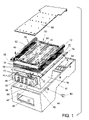
- FIG. 1 is an exploded view taken from aside of the device of the present invention that will be mounted against a wall or surface of a vehicle or other structure to be cooled or heated by the invention;
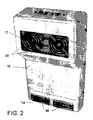
- FIG. 2 is a front, top perspective view of the assembled device of the present invention, in a preferred but not exclusive position for mounting;
- FIG. 3 is a side sectional view of the device of side FIG. 2 ;
- FIG. 4 is an bottom sectional view of the device of FIG. 3 ;
- FIG. 5 is a schematic diagram of one embodiment fo the control section of the device
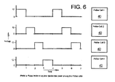
- FIG. 6 is a timing chart illustration one example of how the Petlier units or modules of the invention can be powered
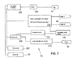
- FIG. 7 is a schematic diagram of another embodiment of the control section of the device.
- FIG. 8 is a schematic circuit diagram of a fan speed controller of the invention.
- FIG. 9 is a schematic circuit diagram of a relay control of the invention.
- FIG. 10 is a schematic circuit diagram of a thermostat interface of the invention.
- FIG. 11 is a view similar to FIG. 3 but of another embodiment of the invention that includes a radiator.
- FIG. 12 is a view similar to FIG. 11 but of another embodiment of the invention that includes a water heating function.
- FIGS. 1 , 2 , 3 and 4 show a device for heating or cooling air, comprising an outer housing 10 , made for example, of fiberglass or other strong rigid material and defining a interior volume.
- the housing 10 has one or more outer inlets 12 communicating with the volume, for receiving air into the volume, and one or more outer outlets 14 , spaced from the outer inlet 12 and also communicating with the volume for discharging air from the volume.
- inlet 12 is preferably covered by a screen.
- An inner housing 16 is provided in the volume of outer housing 10 , and is advantageously made of bent and welded stainless steel to define a box-like casing that fits inside the outer housing.
- the inner housing 16 defines an inlet plenum 18 therein, and has an inner inlet 20 for receiving air from the outer inlet 12 , and into the inlet plenum 18 .
- the inner housing 16 also has an inner outlet 22 in the form of its open bottom end, the inner outlet being spaced from the inner inlet 20 .
- the outer housing 10 defines an outlet plenum 24 that is outside the inner housing 16 and is adjacent the inner outlet 22 of the inner housing.
- a cast aluminum heat sink 30 in the inner housing 16 defines a plurality of air passages 32 , i.e. between parallel spaced apart fins 34 of the heat sink.
- the plural parallel passages extend between the inner inlet 20 and the inner outlet 22 .
- three heat sink sections are mounted side-by-side to form the heat sink.
- At least one fan but in the illustrated embodiment, two fans 36 are mounted in the inlet plenum 18 of the inner housing 16 for moving air from the inner inlet 20 to the inner outlet 22 , so that air moves from the outer inlet 12 , through the inlet plenum 18 , across the passages 32 , into the outlet plenum 24 and out through the outer outlet 14 .
- Baffles 38 are mounted in the outlet 14 so that they can be pivoted from side-to-side and up and down to direct the air as desired as the air leaves the housing assembly.
- thermoelectric modules 40 In order to either cool or heat the air passing through the heat sink passages 32 , a plurality of spaced apart thermoelectric modules 40 , also know as Peltier modules or chips, are mounted in the inner housing 16 , each module having a first or outer surface 42 in heat transfer contact with the heat sink 30 on a side of the heat sink that is opposite to the passages 32 , and each module having an opposite or inner surface 44 .
- thermoelectric module 40 By passing DC current at one polarity through the thermoelectric module 40 , the modules will cool off and therefore cool anything in their vicinity or in heat-transfer contact with the module. Reversing the polarity causes the modules to heat up and likewise heat their surroundings.
- a heat transfer circuit 50 for receiving a heat transfer fluid such as water or other liquid from a location spaced away from the outer housing 10 is provided for moving the heat transfer fluid past the inner surfaces 44 of the modules 40 .
- Air may alternatively be used with means for blowing the air past the surfaces 44 .
- the fluid is water that is drawn from the body of water on which the water craft is floating. This is done, for example by providing the heat transfer circuit 50 with a water supply hose or passage 52 that has an inlet that is dipped into the body of water 100 .
- a liquid pump 54 is connected in the circuit, and, when powered, forces the water into an inlet header pipe 56 , through plural heat transfer tubes 58 that each extend across multiple thermoelectric modules 40 , and empty into an outlet header 60 . From there, the water flows in a return pipe 62 to an outlet hose or passage 64 that discharges the water back into the body of water 100 .
- a fluid exchanging plate 46 of high heat conductivity material is advantageously in heat transfer contact between the tubes 58 and the inner surfaces of the modules 40 and over the tubes 58 and between the cover plate 66 and the tubes to encase the fragile modules 40 and the heat transfer circuit 50 in an high heat transfer and mechanically safe environment.
- an inner cover plate 66 is held, e.g. by multiple screws, against the inner surface of the heat transfer circuit 50 .
- Plate 66 is best made of stainless steel and closes the inner sides of the housings 10 and 16 , protects the pipes of circuit 50 and helps better channel the heat way from the Peltier modules 40 .
- the supply hose or passage 52 can be tapped from any convenient water supply conduit that is already present in the craft or a dedicated hose can be provide that must at least reach into the surface of the body of water.
- the discharge 64 may likewise be present already or a hose or simple opening provided for allowing the water to flow back into the body of water.
- the discharge hose or passage need not reach the surface of the body of water.
- the discharge 64 is connected to the supply hose or passage 52 in a closed loop manifold that includes a radiator 104 or other heat exchanger for cooling the fluid in the manifold, or for heating it, if the unit is being used to heat an environment rather than cool it.
- a radiator 104 or other heat exchanger for cooling the fluid in the manifold, or for heating it, if the unit is being used to heat an environment rather than cool it.
- a water heater capacity can be included as a feature of the invention.
- the invention includes warm water means in the form of, for example, a warm water holding system having a warm water holding tank 106 where warm water may be collected, and four water control valves 108 , 110 , 112 and 114 , e.g. valves that are similar to brass sprinkler valves or electric heater control valves.
- the water from discharge 64 is re-circulated through the tank 106 and to the supply 52 , by opening valves 108 and 110 , to heat the water further as it also cools the Peltier modules 40 .
- the re-circulation is repeated until such time as the water in tank 106 has reached approximately 100 degrees, for example.
- the water may be used for other purposes, e.g. as water for a shower or for other purposes for which warm water is uses, and the system will default back to normal operation.
- opening valves 108 and 110 , and closing valves 112 and 114 water is run into the tank, repeatedly causing it to be heated.
- By reversing or closing valves 108 , 110 and opening valves 112 , 114 the system is restored to normal use.
- a thermostat senses the temperature of water in tank 106 to determine what the valves are to be controlled and to be keep the system balanced. More water from the body of water is supplied to supply pipe 52 through valve 112 and can be discharged back to the body of water by a second discharge pipe 116 and valve 114 .
- the invention also includes a power circuit 70 connected to the thermoelectric modules 40 for powering the modules in a manner for either cooling or heating the heat sink 30 , the power circuit being connected to the fans 36 and pump 54 as well for powering the fan to move air along the passages and the pump to move the water in the heat transfer circuit.
- the housing 10 is substantially vertical as shown in FIG. 2 , and is mounted to a wall or inner hull 102 of the water craft or other vehicle as shown in FIGS. 3 and 4 , for example.
- the housing 10 may alternatively by horizontally mounted or the invention may be built into a wall of the vehicle.
- components that make up the housings 10 and/or 16 may be eliminated or formed by parts of the vehicle itself.
- another feature of the invention is in the unique arrangement of the core of the device, that is the heat sinks 30 with the modules 40 and the heat transfer circuit 50 .
- this core structure whether to be used alone or with one or both of the housings 10 and 16 , includes a pair of side rails 72 that are connected, e.g. by machine screws 74 to the outer heat sinks 30 on either side of the core.
- the number of heat sinks 30 is optional with there being at least one with multiple, e.g. four, Peltier modules 40 there-along, or three heat sinks as shown, or more.
- the heat sinks are connected to each other at the sides, e.g. by welding or bolts, to form a monolithic unit.
- Holes along the rails 72 accommodate screws or bolts 76 for fastening the core to the vehicle wall 102 .
- the inner housing 16 if present, has side flanges 78 with large holes for passing the heads of the screws 76 so that even when the rails 72 are mounted to the wall 102 , the inner housing 16 can be removed if necessary.
- the outer housing 10 has holes in its side walls to receiving fasteners 80 that extend into holes in the outer flanges of rails 72 to fix the outer housing 10 to the core and thus, to the vehicle wall 102 .
- the generally U-shaped side rails 72 also create the needed space and clearance between the wall 102 and the modules 40 with their heat transfer plates 46 , the headers 56 , 60 and tubes 58 forming the water manifold for the heat transfer circuit, and the cover plate 66 .
- the power and control circuit 70 is mounted at one end of the inner housing 16 , in a bracket 82 made of bent stainless steel sheet and fastened to the large end of the housing, e.g. by screws, welding of other means. Bracket 82 also carries a plurality of relays 84 mounted to one or both sides of the bracket. A top plate of the bracket has appropriate openings for carrying an ON/OFF switch 86 , a HOT/COOL switch 88 , a LOW/HIGH switch 90 and a fan speed switch 92 which are wired to the circuit 70 along with the relays 84 .
- a positive and a negative power cord shown at 94 extending from an exposed side of the circuit for connection to a battery, a generator or other source of DC voltage, e.g. a 12 volt power supply of a water craft or other vehicle. Wires 96 also extend from the circuit for connection to the pump 54 .
- a battery of the vehicle of other remote environment for which the present invention is contemplated is the usual power supply, such as, but not limited to any chemical reaction that produces an electric power source, lead-acid, lithium ion, nickel cadmium, or other battery
- various alternative power supplies are possible for the invention as well, such as, but not limited to fuel cells, hydrogen based generators, e.g. electro-mechanical generators or alternator powered by an engine, that are gasoline powered, diesel powered, propane powered, natural gas powered or powered by a jet turbine, or utility power or a device with the ability to convert standard utility power, into a power supply, for the required working voltage as a standard linear type power supply or switching power supply, or solar power, e.g.
- solar panels as a power source and or to recharge a battery pack, large array, stand alone, and small array solar cells for recharging and extending battery life, or even generators from natural events such as wind, water or steam as free energy sources, e.g. windmills, water driven turbines or blades, steam or heated water turbines and the like.
- an end opening 98 is provided in the end wall of outer housing 10 so that when the inner housing 16 is mounted, the switches are accessible.
- one embodiment of the control system of the invention is an AC type device.
- Major differences between this and prior art systems for powering Peltier modules are the fact that all the control systems are derived from a proportional fan speed control 200 that is shown in greater detail in FIG. 8 .
- the Peltier modules 40 are switched in an array, e.g. six at a time, with an AC type power modulation, and directly proportional to the air and coolant temperature as senses by a thermostat 202 and its thermostat interface shown in FIG. 10 .
- Mutable phases supplied by the PWM or Pulse Width Modulation chip drive 204 allow for better efficiency and variable current dependent on demand. External inputs from the thermostat interface of FIG. 10 and from the fan speed control of FIG.
- the system of FIG. 5 thus comprises a Pulse Width Modulation or PWM signal generator 204 for driving an array of thermoelectric modules, e.g. six of the twelve modules in the illustrated embodiment.
- the control system also includes the fan 36 with a fan motor driver 206 , the fan speed controller 200 , the pump 54 , a pump motor driver 208 , a pump controller 210 , the thermostat 202 , a overheat monitor 212 , a temperature sensor 214 , and fan speed selector or speed control switch 92 . These components are operatively connected and configured to minimize the power consumption of the device while maintaining the vehicle cabin temperature at a desired level.
- FIG. 5 is a block diagram of one arrangement of the electrical connection which can be implemented according to the invention.
- the fan controlled in a PWM manner, is used to circulate air through the passages in the heat sink 30 and into the cabin space.
- the other side of the unit is thermally coupled to the liquid flow through heat transfer circuit or exchanger 50 .
- the pump 54 also controlled in a PWM manner, is used to circulate the heat transfer fluid through the heat exchanger 50 .
- a signal generator on circuit 204 modulates the power supplied to each thermoelectric modules 40 , preferably directly proportional to the air and fluid temperature.
- the duty cycle of the PWM signal from the generator is determined based on the input from the thermostat and the fan speed selection.
- thermoelectric modules 40 receive a timed voltage pulse in an ordered or successive manner while the other thermoelectric modules are switched to an inactive (or “OFF”) state. See the timing diagram in FIG. 6 which illustrates the manner in which the voltage pulses can be applied to each of the thermoelectric elements arranged in an array.
- the Peltier modules are divided into groups of (6) six. In the low setting only one group is used, and in the high setting two groups are used. This is how the Hi-Low power settings are achieved.
- the relays 84 are used to allow polarity switching to achieve a heat or cool setting.
- the relays 84 may alternatively be powered by a PWM controller, in phases that are sequential along the length of the heat sink 30 .
- the pulse width is controlled by the relative fan speed setting. This takes place at the GND connection of the relay control, and is sequential depending on the number of banks used.
- the fan speed is variable to allow a comfortable level of air movement.
- Fan speed is controlled by a linear voltage regulator (see the fan speed controller circuit of FIG. 8 ).
- the output of this regulator is the key controller in this embodiment of the invention. It is the one variable that is set externally from the unit. This is the control voltage feedback to the PWM to control the duty cycle of the Peltier modules and the pump speed if need be.
- the pump 54 may or may not be speed or rate controlled, depending on the pump used. It is switched by a relay or switching voltage regulator (see the PWM circuit of FIG. 9 ).
- the thermal limits of operation are monitored by two internal thermostatic switches. They turn off the modules should an excessive temperature be reached by lack of coolant (lake water or other heat carrying liquid) or no airflow.
- the control system consists of switches that turn on the relays, and the thermostat will override the switch settings when the temperature is achieved.
- the Peltier modules will not be totally off, but see a reduced pulse width, thus reducing power consumption.
- FIG. 7 illustrates a simpler embodiment of the control circuit 70 there the thermostat 202 controls the unit and the Peltier modules 40 are switched with the relays 84 to heat or cool in high or low mode via control circuit which is also illustrated in greater detail in FIG. 9 .
- Power management is provided for the pump 54 and for the speed of the fan 36 , which are PWM controlled with feedback from a temperature module 218 and the fan set control or switch 92 .
- the Peltier modules are also divided into groups of (6) six. In the low setting only one group is used, and in the high setting two groups are used. This is how one achieves the Hi-Low power settings.
- the relays 84 are used in all versions to allow polarity switching to achieve a heat or cool setting.
- the fan speed is variable to allow a comfortable level of air movement.
- Fan speed is controlled by a linear voltage regulator ( FIG. 8 ).
- the pump may or may not be speed or rate controlled, depending on the pump used. It will be switched by a relay or switching voltage regulator ( FIG. 9 ).
- the thermal limits of operation are monitored by two internal thermostatic switches. They turn off the modules should an excessive temperature be reached by lack of coolant (lake water or other heat carrying liquid) or no airflow.
- the control system consists of switches that turn on the relays, and the thermostat will override the switch settings when the temperature is achieved.
- FIG. 8 shows the fan speed controller and speed adjustment.
- FIG. 9 shows the relay control for a set of six thermoelectric modules or chips, so that two such circuits are used in the embodiment of FIG. 1 containing twelve chips. Additional circuits of the type shown in FIG. 9 are used to control additional chip sets of larger units and FIG. 10 shows an interface relay set for the thermostat of the invention.
- the pump 54 is controlled with a relay 84 and the protection devices 212 are, for example, bimetallic temperature controlled switches.
Landscapes
- Engineering & Computer Science (AREA)
- Physics & Mathematics (AREA)
- Thermal Sciences (AREA)
- Mechanical Engineering (AREA)
- General Engineering & Computer Science (AREA)
- Chemical & Material Sciences (AREA)
- Combustion & Propulsion (AREA)
- Cooling Or The Like Of Electrical Apparatus (AREA)
Abstract
A device for heating or cooling air, has a housing with an inlet and an outer, as well as an inlet plenum and an outlet plenum for passing air through the housing. A heat sink defines a plurality of air passages between the inlet and outlet and fans in the housing move air through the inlet plenum, across the passages, into the outlet plenum. A plurality of Peltier modules in the housing each have one surface in heat transfer contact with the heat sink and an opposite surface in contact with a heat transfer circuit such as a flow or water in pipes, for cooling or heating the opposite surfaces. A purely relay-based, or PWM-based power circuit is connected to the modules for powering the modules and fans to cool or heat the heat sink.
Description
- The present invention relates generally to the field of air cooling and heating and, in particular to, a new and useful cooling or heating device that operates with Peltier chips or modules, which are also called thermoelectric modules, and on batteries or other lower DC voltage such as the type that would be available on water craft, RV's, other land, sea or air vehicles, or in the outdoors or in work areas where batteries or generators are commonly available.
- The present inventor has also filed a co-pending U.S. patent application having application Ser. No. 11/388,369 filed on Mar. 24, 2006, entitled AIR CONDITIONING SYSTEM FOR WATER CRAFT, which is incorporated hereby reference.
- Peltier or thermoelectric modules have been used in a wide variety of applications for their capacity of either heating up or cooling off when electricity is passed through them at one polarity or at an opposite polarity.
- Some patents that are material to the present invention are:
-
U.S. Pat. No. Inventor(s) 3,255,593 Newton 4,355,518 Beitner 4,955,203 Sundhar 5,072,590 Burrows 5,097,829 Quisenberry 5,269,146 Kerner 5,448,788 Wu 5,566,062 Quisenberry, et al. 5,623,828 Harrington 5,626,021 Karunasiri, et al. 5,690,849 DeVilbiss, et al. 5,966,941 Ghoshal 6,266,962 Ghoshal 6,393,842 Kim, et al. 6,453,678 Sundhar 6,487,865 Luo 6,584,128 Kroeger 6,604,909 Schoenmeyr 6,739,138 Saunders, et al. 6,799,348 Taban 6,880,345 Leija, et al. - Pertinent Patent Applications Include:
-
U.S. Patent Application No. Inventor(s) 20040025516 Van Winkle 20050139692 Yamamoto 20050174737 Meir 20050235652 Iwasaki 20060027357 McKenzie, et al. - Pertinent Publications Include:
- Marlow Industries, Inc., Thermoelectric Design Guide: Power Supplies, available at http://www.marlow.com/TechnicalInfo/power_supplies. htm (last visited Jul. 12, 2006).
- Maxim Integrated Products, Application Note 17571 HFAN-08.2.1: PWM Temperature Controller for Thermoelectric Modules Keeps Components within 0.1° C., available at http://www.maxim-ic.com/appnotes.cfm/appnote_number/1757 (last visited Jul. 12 2006).
- Freescale Semiconductor, Inc., Thermoelectric Cooler Temperature Control, available at http://www.freescale.com/webapp/sps/site/application.jsp?nodeld=023Z1Dxp CpksmP (last visited Jul. 12, 2006). TelCom Semiconductor, Inc., Application Note 58: Suppressing Acoustic Noise in PWM Fan Speed Control Systems, available at http://www.cpemma.co.uk/an58.pdf (last visited Jul. 14, 2006).
- U.S. Published Patent Application 20040025516 to Van Winkle, which was cited during the prosecution of application Ser. No. 11/388,369 identified above, discloses a thermoelectric module based water cooler for boats or other vehicles, that uses two fluid heat transfer loops on opposite sides of the modules.
- U.S. Pat. No. 5,097,829 to Quisenberry (or the “Quisenberry '829 patent”) generally discloses a cooling system having a device for powering the thermoelectric cooler (TEC) with pulse width modulated electrical signals. See abstract; and col. 3, lines 23-27.
- U.S. Pat. No. 6,266,962 to Ghoshal discloses a thermoelectric cooling apparatus having a source for providing signals to one or more thermoelectric coolers (TECs) to periodically alter each TEC between an active and passive state.
- U.S. Pat. No. 6,739,138 to Saunders, et al. discloses a cooling and heating apparatus that is applied to an object to control the temperature of the object.
- It is an object of the present invention to provide a device for heating or cooling air, comprising: an outer housing defining a volume, the housing having an outer inlet communicating with the volume for receiving air into the volume and an outer outlet spaced from the outer inlet and also communicating with the volume for discharging air from the volume; an inner housing in the volume, the inner housing defining an inlet plenum therein and having an inner inlet for receiving air from the outer inlet and into the inlet plenum, the inner housing having an inner outlet spaced from the inner inlet; the outer housing having an outlet plenum that is outside the inner housing and adjacent the inner outlet of the inner housing; a heat sink in the inner housing, defining a plurality of air passages between the inner inlet and the inner outlet; at least one fan mounted in the inner housing for moving air from the inner inlet to the inner outlet so that air moves from the outer inlet, through the inlet plenum, across the passages, into the outlet plenum and out through the outer outlet; a plurality of spaced apart thermoelectric modules in the inner housing, each module having a first surface in heat transfer contact with the heat sink on a side of the heat sink that is opposite to the passages, and each module having an opposite surface; a heat transfer circuit for receiving a heat transfer fluid from a location spaced away from the outer inlet and outer outlet, and for moving the heat transfer fluid past the opposite surfaces of the modules; and a power circuit connected to the thermoelectric modules for powering the modules in a manner for either cooling or heating the heat sink, the power circuit being connected to the fan for powering the fan to move air along the passages.
- It is another object of the present invention to provide a power circuit as a relay-based circuit, or as a PWM (Pulse Width Modulated) circuit for operating the thermoelectric modules in sets for energy conservation and level or heating or cooling desired.
- According to a still further object of the invention, the device comprises a core unit for heating or cooling
- The various features of novelty which characterize the invention are pointed out with particularity in the claims annexed to and forming a part of this disclosure. For a better understanding of the invention, its operating advantages and specific objects attained by its uses, reference is made to the accompanying drawings and descriptive matter in which preferred embodiments of the invention are illustrated.
- In the drawings:
-
FIG. 1 is an exploded view taken from aside of the device of the present invention that will be mounted against a wall or surface of a vehicle or other structure to be cooled or heated by the invention; -
FIG. 2 is a front, top perspective view of the assembled device of the present invention, in a preferred but not exclusive position for mounting; -
FIG. 3 is a side sectional view of the device of sideFIG. 2 ; -
FIG. 4 is an bottom sectional view of the device ofFIG. 3 ; -
FIG. 5 is a schematic diagram of one embodiment fo the control section of the device; -
FIG. 6 is a timing chart illustration one example of how the Petlier units or modules of the invention can be powered; -
FIG. 7 is a schematic diagram of another embodiment of the control section of the device; -
FIG. 8 is a schematic circuit diagram of a fan speed controller of the invention; -
FIG. 9 is a schematic circuit diagram of a relay control of the invention; -
FIG. 10 is a schematic circuit diagram of a thermostat interface of the invention; -
FIG. 11 is a view similar toFIG. 3 but of another embodiment of the invention that includes a radiator; and -
FIG. 12 is a view similar toFIG. 11 but of another embodiment of the invention that includes a water heating function. - Referring now to the drawings, in which like reference numerals are used to refer to the same or similar elements,
FIGS. 1 , 2, 3 and 4 show a device for heating or cooling air, comprising anouter housing 10, made for example, of fiberglass or other strong rigid material and defining a interior volume. Thehousing 10 has one or moreouter inlets 12 communicating with the volume, for receiving air into the volume, and one or moreouter outlets 14, spaced from theouter inlet 12 and also communicating with the volume for discharging air from the volume. As shown inFIG. 3 ,inlet 12 is preferably covered by a screen. - An
inner housing 16 is provided in the volume ofouter housing 10, and is advantageously made of bent and welded stainless steel to define a box-like casing that fits inside the outer housing. Theinner housing 16 defines aninlet plenum 18 therein, and has aninner inlet 20 for receiving air from theouter inlet 12, and into theinlet plenum 18. Theinner housing 16 also has aninner outlet 22 in the form of its open bottom end, the inner outlet being spaced from theinner inlet 20. Theouter housing 10 defines anoutlet plenum 24 that is outside theinner housing 16 and is adjacent theinner outlet 22 of the inner housing. - A cast
aluminum heat sink 30 in theinner housing 16, defines a plurality ofair passages 32, i.e. between parallel spaced apartfins 34 of the heat sink. - The plural parallel passages extend between the
inner inlet 20 and theinner outlet 22. In the embodiment ofFIG. 1 , three heat sink sections are mounted side-by-side to form the heat sink. - At least one fan, but in the illustrated embodiment, two
fans 36 are mounted in theinlet plenum 18 of theinner housing 16 for moving air from theinner inlet 20 to theinner outlet 22, so that air moves from theouter inlet 12, through theinlet plenum 18, across thepassages 32, into theoutlet plenum 24 and out through theouter outlet 14.Baffles 38 are mounted in theoutlet 14 so that they can be pivoted from side-to-side and up and down to direct the air as desired as the air leaves the housing assembly. - In order to either cool or heat the air passing through the
heat sink passages 32, a plurality of spaced apartthermoelectric modules 40, also know as Peltier modules or chips, are mounted in theinner housing 16, each module having a first orouter surface 42 in heat transfer contact with theheat sink 30 on a side of the heat sink that is opposite to thepassages 32, and each module having an opposite orinner surface 44. As is know, by passing DC current at one polarity through thethermoelectric module 40, the modules will cool off and therefore cool anything in their vicinity or in heat-transfer contact with the module. Reversing the polarity causes the modules to heat up and likewise heat their surroundings. - Since the cooling or heating of the Peltier modules can quickly become excessive and pose a danger of damaging the units, according to the present invention, a
heat transfer circuit 50 for receiving a heat transfer fluid such as water or other liquid from a location spaced away from theouter housing 10, is provided for moving the heat transfer fluid past theinner surfaces 44 of themodules 40. Air may alternatively be used with means for blowing the air past thesurfaces 44. - In a preferred embodiment of the invention for use as an air conditioner (air cooler) or air heated in a water craft, the fluid is water that is drawn from the body of water on which the water craft is floating. This is done, for example by providing the
heat transfer circuit 50 with a water supply hose orpassage 52 that has an inlet that is dipped into the body ofwater 100. Aliquid pump 54 is connected in the circuit, and, when powered, forces the water into aninlet header pipe 56, through pluralheat transfer tubes 58 that each extend across multiplethermoelectric modules 40, and empty into anoutlet header 60. From there, the water flows in areturn pipe 62 to an outlet hose orpassage 64 that discharges the water back into the body ofwater 100. Afluid exchanging plate 46 of high heat conductivity material is advantageously in heat transfer contact between thetubes 58 and the inner surfaces of themodules 40 and over thetubes 58 and between thecover plate 66 and the tubes to encase thefragile modules 40 and theheat transfer circuit 50 in an high heat transfer and mechanically safe environment. - As shown in
FIGS. 1 , 3 and 4, aninner cover plate 66 is held, e.g. by multiple screws, against the inner surface of theheat transfer circuit 50.Plate 66 is best made of stainless steel and closes the inner sides of thehousings circuit 50 and helps better channel the heat way from thePeltier modules 40. - The supply hose or
passage 52 can be tapped from any convenient water supply conduit that is already present in the craft or a dedicated hose can be provide that must at least reach into the surface of the body of water. Thedischarge 64 may likewise be present already or a hose or simple opening provided for allowing the water to flow back into the body of water. The discharge hose or passage need not reach the surface of the body of water. - In an alternate embodiment of the invention shown in
FIG. 11 , thedischarge 64 is connected to the supply hose orpassage 52 in a closed loop manifold that includes aradiator 104 or other heat exchanger for cooling the fluid in the manifold, or for heating it, if the unit is being used to heat an environment rather than cool it. - In a further embodiment of the invention shown in
FIG. 12 , a water heater capacity can be included as a feature of the invention. In this embodiment, the invention includes warm water means in the form of, for example, a warm water holding system having a warmwater holding tank 106 where warm water may be collected, and fourwater control valves discharge 64 is re-circulated through thetank 106 and to thesupply 52, by openingvalves Peltier modules 40. The re-circulation is repeated until such time as the water intank 106 has reached approximately 100 degrees, for example. At this point the water may be used for other purposes, e.g. as water for a shower or for other purposes for which warm water is uses, and the system will default back to normal operation. By openingvalves valves valves valves tank 106 to determine what the valves are to be controlled and to be keep the system balanced. More water from the body of water is supplied to supplypipe 52 throughvalve 112 and can be discharged back to the body of water by asecond discharge pipe 116 andvalve 114. - The invention also includes a
power circuit 70 connected to thethermoelectric modules 40 for powering the modules in a manner for either cooling or heating theheat sink 30, the power circuit being connected to thefans 36 and pump 54 as well for powering the fan to move air along the passages and the pump to move the water in the heat transfer circuit. - According to one possible mounting arrangement of the invention, the
housing 10 is substantially vertical as shown inFIG. 2 , and is mounted to a wall orinner hull 102 of the water craft or other vehicle as shown inFIGS. 3 and 4 , for example. Thehousing 10 may alternatively by horizontally mounted or the invention may be built into a wall of the vehicle. In the case of a built-in version of the invention, components that make up thehousings 10 and/or 16 may be eliminated or formed by parts of the vehicle itself. Accordingly, another feature of the invention is in the unique arrangement of the core of the device, that is the heat sinks 30 with themodules 40 and theheat transfer circuit 50. - According to one embodiment of the invention, this core structure, whether to be used alone or with one or both of the
housings machine screws 74 to theouter heat sinks 30 on either side of the core. The number ofheat sinks 30 is optional with there being at least one with multiple, e.g. four,Peltier modules 40 there-along, or three heat sinks as shown, or more. The heat sinks are connected to each other at the sides, e.g. by welding or bolts, to form a monolithic unit. - Holes along the
rails 72 accommodate screws or bolts 76 for fastening the core to thevehicle wall 102. Theinner housing 16, if present, hasside flanges 78 with large holes for passing the heads of the screws 76 so that even when therails 72 are mounted to thewall 102, theinner housing 16 can be removed if necessary. Theouter housing 10 has holes in its side walls to receivingfasteners 80 that extend into holes in the outer flanges ofrails 72 to fix theouter housing 10 to the core and thus, to thevehicle wall 102. - The generally U-shaped side rails 72 also create the needed space and clearance between the
wall 102 and themodules 40 with theirheat transfer plates 46, theheaders tubes 58 forming the water manifold for the heat transfer circuit, and thecover plate 66. - The power and
control circuit 70 is mounted at one end of theinner housing 16, in a bracket 82 made of bent stainless steel sheet and fastened to the large end of the housing, e.g. by screws, welding of other means. Bracket 82 also carries a plurality ofrelays 84 mounted to one or both sides of the bracket. A top plate of the bracket has appropriate openings for carrying an ON/OFF switch 86, a HOT/COOL switch 88, a LOW/HIGH switch 90 and afan speed switch 92 which are wired to thecircuit 70 along with therelays 84. A positive and a negative power cord shown at 94 extending from an exposed side of the circuit for connection to a battery, a generator or other source of DC voltage, e.g. a 12 volt power supply of a water craft or other vehicle.Wires 96 also extend from the circuit for connection to thepump 54. - Although a battery of the vehicle of other remote environment for which the present invention is contemplated, is the usual power supply, such as, but not limited to any chemical reaction that produces an electric power source, lead-acid, lithium ion, nickel cadmium, or other battery, various alternative power supplies are possible for the invention as well, such as, but not limited to fuel cells, hydrogen based generators, e.g. electro-mechanical generators or alternator powered by an engine, that are gasoline powered, diesel powered, propane powered, natural gas powered or powered by a jet turbine, or utility power or a device with the ability to convert standard utility power, into a power supply, for the required working voltage as a standard linear type power supply or switching power supply, or solar power, e.g. solar panels as a power source and or to recharge a battery pack, large array, stand alone, and small array solar cells for recharging and extending battery life, or even generators from natural events such as wind, water or steam as free energy sources, e.g. windmills, water driven turbines or blades, steam or heated water turbines and the like.
- Returning to the drawings, an
end opening 98 is provided in the end wall ofouter housing 10 so that when theinner housing 16 is mounted, the switches are accessible. - As shown in
FIG. 5 , one embodiment of the control system of the invention is an AC type device. Major differences between this and prior art systems for powering Peltier modules are the fact that all the control systems are derived from a proportionalfan speed control 200 that is shown in greater detail inFIG. 8 . ThePeltier modules 40 are switched in an array, e.g. six at a time, with an AC type power modulation, and directly proportional to the air and coolant temperature as senses by athermostat 202 and its thermostat interface shown inFIG. 10 . Mutable phases supplied by the PWM or Pulse WidthModulation chip drive 204, allow for better efficiency and variable current dependent on demand. External inputs from the thermostat interface ofFIG. 10 and from the fan speed control ofFIG. 8 , determine the digital duty cycle that the system is switched at. All drivers, fan and pump, are of the PWM type to also gain efficiency. This allows the unit to adjust itself for minimum power at any preset airflow level. The switching frequency of approximately 25 KHz for example, provides a signal to lock for additional units into the same control loop and not require any EMI or RFI concerns. In units that require more thermoelectric modules for cooling or heating may have additional outputs to further split up the distribution of power to the various Peltier modules. - The system of
FIG. 5 thus comprises a Pulse Width Modulation orPWM signal generator 204 for driving an array of thermoelectric modules, e.g. six of the twelve modules in the illustrated embodiment. The control system also includes thefan 36 with afan motor driver 206, thefan speed controller 200, thepump 54, apump motor driver 208, apump controller 210, thethermostat 202, aoverheat monitor 212, atemperature sensor 214, and fan speed selector orspeed control switch 92. These components are operatively connected and configured to minimize the power consumption of the device while maintaining the vehicle cabin temperature at a desired level.FIG. 5 is a block diagram of one arrangement of the electrical connection which can be implemented according to the invention. - The fan, controlled in a PWM manner, is used to circulate air through the passages in the
heat sink 30 and into the cabin space. The other side of the unit is thermally coupled to the liquid flow through heat transfer circuit orexchanger 50. Thepump 54, also controlled in a PWM manner, is used to circulate the heat transfer fluid through theheat exchanger 50. - A signal generator on
circuit 204 modulates the power supplied to eachthermoelectric modules 40, preferably directly proportional to the air and fluid temperature. The duty cycle of the PWM signal from the generator is determined based on the input from the thermostat and the fan speed selection. - In one operational arrangement, some of the
thermoelectric modules 40 receive a timed voltage pulse in an ordered or successive manner while the other thermoelectric modules are switched to an inactive (or “OFF”) state. See the timing diagram inFIG. 6 which illustrates the manner in which the voltage pulses can be applied to each of the thermoelectric elements arranged in an array. - In
FIG. 5 the Peltier modules are divided into groups of (6) six. In the low setting only one group is used, and in the high setting two groups are used. This is how the Hi-Low power settings are achieved. Therelays 84 are used to allow polarity switching to achieve a heat or cool setting. Therelays 84 may alternatively be powered by a PWM controller, in phases that are sequential along the length of theheat sink 30. The pulse width is controlled by the relative fan speed setting. This takes place at the GND connection of the relay control, and is sequential depending on the number of banks used. - The fan speed is variable to allow a comfortable level of air movement. Fan speed is controlled by a linear voltage regulator (see the fan speed controller circuit of
FIG. 8 ). The output of this regulator is the key controller in this embodiment of the invention. It is the one variable that is set externally from the unit. This is the control voltage feedback to the PWM to control the duty cycle of the Peltier modules and the pump speed if need be. - The
pump 54 may or may not be speed or rate controlled, depending on the pump used. It is switched by a relay or switching voltage regulator (see the PWM circuit ofFIG. 9 ). - The thermal limits of operation are monitored by two internal thermostatic switches. They turn off the modules should an excessive temperature be reached by lack of coolant (lake water or other heat carrying liquid) or no airflow.
- The control system consists of switches that turn on the relays, and the thermostat will override the switch settings when the temperature is achieved. The Peltier modules will not be totally off, but see a reduced pulse width, thus reducing power consumption.
-
FIG. 7 illustrates a simpler embodiment of thecontrol circuit 70 there thethermostat 202 controls the unit and thePeltier modules 40 are switched with therelays 84 to heat or cool in high or low mode via control circuit which is also illustrated in greater detail inFIG. 9 . Power management is provided for thepump 54 and for the speed of thefan 36, which are PWM controlled with feedback from atemperature module 218 and the fan set control orswitch 92. - In the circuit of
FIG. 7 , the Peltier modules are also divided into groups of (6) six. In the low setting only one group is used, and in the high setting two groups are used. This is how one achieves the Hi-Low power settings. Therelays 84 are used in all versions to allow polarity switching to achieve a heat or cool setting. - The fan speed is variable to allow a comfortable level of air movement.
- Fan speed is controlled by a linear voltage regulator (
FIG. 8 ). The pump may or may not be speed or rate controlled, depending on the pump used. It will be switched by a relay or switching voltage regulator (FIG. 9 ). - The thermal limits of operation are monitored by two internal thermostatic switches. They turn off the modules should an excessive temperature be reached by lack of coolant (lake water or other heat carrying liquid) or no airflow.
- The control system consists of switches that turn on the relays, and the thermostat will override the switch settings when the temperature is achieved.
-
FIG. 8 shows the fan speed controller and speed adjustment.FIG. 9 shows the relay control for a set of six thermoelectric modules or chips, so that two such circuits are used in the embodiment ofFIG. 1 containing twelve chips. Additional circuits of the type shown inFIG. 9 are used to control additional chip sets of larger units andFIG. 10 shows an interface relay set for the thermostat of the invention. Thepump 54 is controlled with arelay 84 and theprotection devices 212 are, for example, bimetallic temperature controlled switches. - While specific embodiments of the invention have been shown and described in detail to illustrate the application of the principles of the invention, it will be understood that the invention may be embodied otherwise without departing from such principles.
Claims (22)
1. A device for heating or cooling air, comprising:
an outer housing defining a volume, the housing having an outer inlet communicating with the volume for receiving air into the volume and an outer outlet spaced from the outer inlet and also communicating with the volume for discharging air from the volume;
an inner housing in the volume, the inner housing defining an inlet plenum therein and having an inner inlet for receiving air from the outer inlet and into the inlet plenum, the inner housing having an inner outlet spaced from the inner inlet;
the outer housing having an outlet plenum that is outside the inner housing and adjacent the inner outlet of the inner housing;
a heat sink in the inner housing, defining a plurality of air passages between the inner inlet and the inner outlet;
at least one fan mounted in the inner housing for moving air from the inner inlet to the inner outlet so that air moves from the outer inlet, through the inlet plenum, across the passages, into the outlet plenum and out through the outer outlet;
a plurality of spaced apart thermoelectric modules in the inner housing, each module having a first surface in heat transfer contact with the heat sink on a side of the heat sink that is opposite to the passages, and each module having an opposite surface;
a heat transfer circuit for receiving a heat transfer fluid from a location spaced away from the outer inlet and outer outlet, and for moving the heat transfer fluid past the opposite surfaces of the modules; and
a power circuit connected to the thermoelectric modules for powering the modules in a manner for one of cooling and heating the heat sink, the power circuit being connected to the fan for powering the fan to move air along the passages.
2. A device according to claim 1 , wherein the heat transfer circuit comprises a manifold for placing a flow of water in heat transfer contact with the opposite surfaces of the thermoelectric modules, a pump connected to the manifold for pumping water through the manifold and means for defining an inlet passage and an outlet passage for water to and from the pump and a body of water.
3. A device according to claim 1 , wherein the heat transfer circuit comprises a manifold for placing a flow of water in heat transfer contact with the opposite surfaces of the thermoelectric modules, a pump connected to the manifold for pumping water through the manifold and means for defining an inlet passage and an outlet passage for water to and from the pump and a radiator.
4. A device according to claim 1 , wherein the heat sink comprises a solid base and a plurality of fins extending from one side of the base for defining the plurality of air passages.
5. A device according to claim 1 , wherein the heat transfer circuit comprises a manifold for placing a flow of water in heat transfer contact with the opposite surfaces of the thermoelectric modules, a pump connected to the manifold for pumping water through the manifold and means for defining an inlet passage and an outlet passage for water to and from the pump and a body of water, the heat sink having a solid base and a plurality of fins extending from one side of the base and defining the plurality of air passages.
6. A device according to claim 1 , wherein the plurality of modules are separated into at least two module sets, the power circuit being connected to the modules for selectively powering one set only or both sets at one time.
7. A device according to claim 1 , wherein the plurality of modules are separated into at least two module sets, the power circuit including pulse width modulation means connected to the modules for selectively powering one set at a time.
8. A device according to claim 1 , including a cover plate connected over the heat transfer circuit and a bracket connected to a wall of the inner housing adjacent the fan, the power circuit being mounted to the bracket and having a plurality of control switches that are accessible through an opening in the outer housing that is over the bracket.
9. A device according to claim 1 , wherein the heat transfer circuit comprises a manifold for placing a flow of water in heat transfer contact with the opposite surfaces of the thermoelectric modules, a pump connected to the manifold for pumping water through the manifold and means for defining an inlet passage and an outlet passage for water to and from the pump and a radiator, and water heater means connected to the radiator for discharging a supply of warm water for use.
10. A core device for heating or cooling air, comprising:
a heat sink having a solid base and a plurality of fins extending from one side of the base and defining a plurality of air passages between an inlet on one end of the heat sink and an outlet on an opposite end of the heat sink;
at least one fan mounted for moving air from the inlet to the outlet so that air moves across the passages;
a plurality of thermoelectric modules each having a first surface in heat transfer contact with the heat sink on an opposite side of the base from the fins, the modules being spaced alone the base, parallel to the passages, and each module having an opposite surface;
a heat transfer circuit for receiving a heat transfer fluid from a location spaced away from the inlet and outlet, and for moving the heat transfer fluid past the opposite surfaces of the modules; and
a power circuit connected to the thermoelectric modules for powering the modules in a manner for one of cooling and heating the heat sink, the power circuit being connected to the fan for powering the fan to move air along the passages.
11. A core device according to claim 10 , wherein the heat transfer circuit comprises a manifold for placing a flow of water in heat transfer contact with the opposite surfaces of the thermoelectric modules, a pump connected to the manifold for pumping water through the manifold and means for defining an inlet passage and an outlet passage for water to and from the pump and a body of water.
12. A core device according to claim 10 , including a pair of mounting rails on opposite sides of the heat sink for mounting the heat sink to a support, the rails creating a clearance for the plurality of thermoelectric modules with the heat transfer circuit, and the support.
13. A core device according to claim 10 , wherein the heat transfer circuit comprises a manifold for placing a flow of water in heat transfer contact with the opposite surfaces of the thermoelectric modules, a pump connected to the manifold for pumping water through the manifold and means for defining an inlet passage and an outlet passage for water to and from the pump and a body of water.
14. A core device according to claim 10 , wherein the heat transfer circuit comprises a manifold for placing a flow of water in heat transfer contact with the opposite surfaces of the thermoelectric modules, a pump connected to the manifold for pumping water through the manifold and means for defining an inlet passage and an outlet passage for water to and from the pump and a radiator.
15. A core device according to claim 10 , wherein the plurality of modules are separated into at least two module sets, the power circuit being connected to the modules for selectively powering one set only or both sets at one time.
16. A core device according to claim 10 , wherein the plurality of modules are separated into at least two module sets, the power circuit including pulse width modulation means connected to the modules for selectively powering one set at a time.
17. A core device according to claim 10 , including a cover plate connected over the heat transfer circuit, an housing extending over the heat sink, the fan being mounted to the housing and a bracket connected to a wall of the housing adjacent the fan, the power circuit being mounted to the bracket and having a plurality of control switches.
18. A core device according to claim 10 , wherein the heat transfer circuit comprises a manifold for placing a flow of water in heat transfer contact with the opposite surfaces of the thermoelectric modules, a pump connected to the manifold for pumping water through the manifold and means for defining an inlet passage and an outlet passage for water to and from the pump and a radiator, and water heater means connected to the radiator for discharging a supply of warm water for use.
19. A device for heating or cooling air, comprising:
a fan for moving air;
a plurality of thermoelectric modules mounted for receiving a flow of air from the fan for cooling of heating the air; and
a power circuit connected to the thermoelectric modules for powering the modules in a manner for cooling or for heating the air, the power circuit being connected to the fan for powering the fan;
the power circuit comprising a fan speed controller for controlling the speed of the fan, a thermostat interrupting power to the fan and to the modules when a selected temperature is reached, and means for selectively powering the modules so that fewer than all the modules can be powered
20. A core device according to claim 19 , wherein the plurality of modules are separated into at least two module sets, the means for selectively powering the modules being connected to the modules for selectively powering one set only or both sets at one time.
21. A core device according to claim 19 , wherein the plurality of modules are separated into at least two module sets, the means for selectively powering the modules comprising pulse width modulation means connected to the modules for selectively powering one set at a time.
22. A core device according to claim 19 , including a heat transfer circuit comprising a manifold for placing a flow of water in heat transfer contact with surfaces of the thermoelectric modules, a pump connected to the manifold for pumping water through the manifold and means for defining an inlet passage and an outlet passage for water to and from the pump and a radiator, and water heater means connected to the radiator for discharging a supply of warm water for use.
Priority Applications (1)
| Application Number | Priority Date | Filing Date | Title |
|---|---|---|---|
| US11/553,655 US20080098750A1 (en) | 2006-10-27 | 2006-10-27 | Thermoelectric cooling/heating device |
Applications Claiming Priority (1)
| Application Number | Priority Date | Filing Date | Title |
|---|---|---|---|
| US11/553,655 US20080098750A1 (en) | 2006-10-27 | 2006-10-27 | Thermoelectric cooling/heating device |
Publications (1)
| Publication Number | Publication Date |
|---|---|
| US20080098750A1 true US20080098750A1 (en) | 2008-05-01 |
Family
ID=39328510
Family Applications (1)
| Application Number | Title | Priority Date | Filing Date |
|---|---|---|---|
| US11/553,655 Abandoned US20080098750A1 (en) | 2006-10-27 | 2006-10-27 | Thermoelectric cooling/heating device |
Country Status (1)
| Country | Link |
|---|---|
| US (1) | US20080098750A1 (en) |
Cited By (30)
| Publication number | Priority date | Publication date | Assignee | Title |
|---|---|---|---|---|
| US20080218140A1 (en) * | 2007-02-08 | 2008-09-11 | Chih-Peng Liao | Control apparatus for cooler |
| US20090229274A1 (en) * | 2008-03-13 | 2009-09-17 | Andre Boulay | Thermoelectric retrofit unit for a liquid recipient |
| US20110135520A1 (en) * | 2009-12-07 | 2011-06-09 | Debabrata Pal | Injection molded fan motor controller housing with advanced cooling features |
| US20120073309A1 (en) * | 2010-09-29 | 2012-03-29 | Industrial Technology Research Institute | Thermoelectric drinking apparatus and thermoelectric heat pump |
| US20120262040A1 (en) * | 2011-04-12 | 2012-10-18 | Mr. Jon Karpovich | Solar panel housing |
| US20120270494A1 (en) * | 2011-04-20 | 2012-10-25 | Mccarty Daniel P | Displacement-induction neutral wall air terminal unit |
| US8516832B2 (en) | 2010-08-30 | 2013-08-27 | B/E Aerospace, Inc. | Control system for a food and beverage compartment thermoelectric cooling system |
| US20130291555A1 (en) * | 2012-05-07 | 2013-11-07 | Phononic Devices, Inc. | Thermoelectric refrigeration system control scheme for high efficiency performance |
| WO2014036240A1 (en) * | 2012-08-31 | 2014-03-06 | Ringdale, Inc. | Air-conditioning system |
| US8893513B2 (en) | 2012-05-07 | 2014-11-25 | Phononic Device, Inc. | Thermoelectric heat exchanger component including protective heat spreading lid and optimal thermal interface resistance |
| US20150007583A1 (en) * | 2012-01-13 | 2015-01-08 | Toyota Jidosha Kabushiki Kaisha | Temperature adjustment apparatus and method of controlling peltier element |
| US20150206776A1 (en) * | 2012-07-25 | 2015-07-23 | Kelk Ltd. | Temperature Controller for Semiconductor Manufacturing Equipment, Method for Calculating PID Constants in Semiconductor Manfacturing, and Method for Operating Temperature Controller for Semiconductor Manufacturing Equipment |
| US9144180B2 (en) | 2013-10-28 | 2015-09-22 | Phononic Devices, Inc. | Thermoelectric heat pump with a surround and spacer (SAS) structure |
| US20160018141A1 (en) * | 2014-07-21 | 2016-01-21 | Phononic Devices, Inc. | Systems and methods for mitigating heat rejection limitations of a thermoelectric module |
| USD749713S1 (en) * | 2014-07-31 | 2016-02-16 | Innovative Medical Equipment, Llc | Heat exchanger |
| US9593871B2 (en) | 2014-07-21 | 2017-03-14 | Phononic Devices, Inc. | Systems and methods for operating a thermoelectric module to increase efficiency |
| WO2017059443A1 (en) * | 2015-10-01 | 2017-04-06 | Hoffman Enclosures, Inc. | Reduced footprint thermoelectric cooler controller |
| WO2017059520A1 (en) * | 2015-10-07 | 2017-04-13 | Campeau Gerard | Thermoelectric generator using in situ passive cooling |
| CN106662379A (en) * | 2014-07-21 | 2017-05-10 | 弗诺尼克设备公司 | Systems and methods for mitigating heat rejection limitations of a thermoelectric module |
| US20170299237A1 (en) * | 2016-04-17 | 2017-10-19 | Andrew Xianyi Huang | Solar-powered system |
| US10072881B2 (en) | 2014-11-26 | 2018-09-11 | Hoffman Enclosures, Inc. | Reduced footprint thermoelectric cooler controller |
| CN108966587A (en) * | 2017-10-13 | 2018-12-07 | 邹昊雄 | A kind of radiator |
| US10502463B2 (en) | 2014-11-26 | 2019-12-10 | Hoffman Enclosures, Inc. | Thermoelectric cooler controller and angled mounting thereof |
| US10600722B1 (en) | 2018-12-04 | 2020-03-24 | Denso International America, Inc. | Heat sink for alternator |
| WO2020065219A1 (en) * | 2018-09-27 | 2020-04-02 | Valeo Systemes Thermiques | Motor vehicle ventilator |
| CN113113327A (en) * | 2020-01-13 | 2021-07-13 | 方珉喆 | Temperature control device for chemical liquid for semiconductor manufacturing |
| US11167618B2 (en) * | 2015-07-23 | 2021-11-09 | Hyundai Motor Company | Combined heat exchanger module |
| US11234348B2 (en) * | 2019-01-17 | 2022-01-25 | Lsis Co., Ltd. | Heatsink module for inverter |
| WO2024135995A1 (en) * | 2022-12-20 | 2024-06-27 | 코웨이 주식회사 | Water purifier that uses waste heat from thermoelectric element |
| US12504185B2 (en) | 2022-10-05 | 2025-12-23 | Daniel P. McCarty | Integrated ventilation and heat recovery terminal |
Citations (1)
| Publication number | Priority date | Publication date | Assignee | Title |
|---|---|---|---|---|
| US5371665A (en) * | 1994-03-14 | 1994-12-06 | Quisenberry; Tony M. | Power control circuit for improved power application and temperature control of thermoelectric coolers and method for controlling thereof |
-
2006
- 2006-10-27 US US11/553,655 patent/US20080098750A1/en not_active Abandoned
Patent Citations (1)
| Publication number | Priority date | Publication date | Assignee | Title |
|---|---|---|---|---|
| US5371665A (en) * | 1994-03-14 | 1994-12-06 | Quisenberry; Tony M. | Power control circuit for improved power application and temperature control of thermoelectric coolers and method for controlling thereof |
Cited By (56)
| Publication number | Priority date | Publication date | Assignee | Title |
|---|---|---|---|---|
| US20080218140A1 (en) * | 2007-02-08 | 2008-09-11 | Chih-Peng Liao | Control apparatus for cooler |
| US20090229274A1 (en) * | 2008-03-13 | 2009-09-17 | Andre Boulay | Thermoelectric retrofit unit for a liquid recipient |
| US20110135520A1 (en) * | 2009-12-07 | 2011-06-09 | Debabrata Pal | Injection molded fan motor controller housing with advanced cooling features |
| US8308451B2 (en) | 2009-12-07 | 2012-11-13 | Hamilton Sundstrand Corporation | Injection molded fan motor controller housing with advanced cooling features |
| US8516832B2 (en) | 2010-08-30 | 2013-08-27 | B/E Aerospace, Inc. | Control system for a food and beverage compartment thermoelectric cooling system |
| US20120073309A1 (en) * | 2010-09-29 | 2012-03-29 | Industrial Technology Research Institute | Thermoelectric drinking apparatus and thermoelectric heat pump |
| US9310110B2 (en) * | 2010-09-29 | 2016-04-12 | Industrial Technology Research Institute | Thermoelectric drinking apparatus and thermoelectric heat pump |
| US10461205B2 (en) | 2011-04-12 | 2019-10-29 | Rajul R. Patel | Solar panel housing |
| US20120262040A1 (en) * | 2011-04-12 | 2012-10-18 | Mr. Jon Karpovich | Solar panel housing |
| US9082913B2 (en) * | 2011-04-12 | 2015-07-14 | Rajul R. Patel | Solar panel housing |
| US9982899B2 (en) | 2011-04-20 | 2018-05-29 | Daniel P. McCarty | Displacement-induction neutral wall air terminal unit |
| US9551496B2 (en) * | 2011-04-20 | 2017-01-24 | Dan P. McCarty | Displacement-induction neutral wall air terminal unit |
| US20120270494A1 (en) * | 2011-04-20 | 2012-10-25 | Mccarty Daniel P | Displacement-induction neutral wall air terminal unit |
| US20150007583A1 (en) * | 2012-01-13 | 2015-01-08 | Toyota Jidosha Kabushiki Kaisha | Temperature adjustment apparatus and method of controlling peltier element |
| US9719702B2 (en) * | 2012-01-13 | 2017-08-01 | Toyota Jidosha Kabushiki Kaisha | Temperature adjustment apparatus and method of controlling Peltier element |
| CN104040783B (en) * | 2012-01-13 | 2016-09-28 | 丰田自动车株式会社 | Temperature adjustment device, the control method of Peltier's element |
| US20130291556A1 (en) * | 2012-05-07 | 2013-11-07 | Phononic Devices, Inc. | Systems and methods to mitigate heat leak back in a thermoelectric refrigeration system |
| US20130291555A1 (en) * | 2012-05-07 | 2013-11-07 | Phononic Devices, Inc. | Thermoelectric refrigeration system control scheme for high efficiency performance |
| US8991194B2 (en) * | 2012-05-07 | 2015-03-31 | Phononic Devices, Inc. | Parallel thermoelectric heat exchange systems |
| US8893513B2 (en) | 2012-05-07 | 2014-11-25 | Phononic Device, Inc. | Thermoelectric heat exchanger component including protective heat spreading lid and optimal thermal interface resistance |
| US10012417B2 (en) * | 2012-05-07 | 2018-07-03 | Phononic, Inc. | Thermoelectric refrigeration system control scheme for high efficiency performance |
| US9103572B2 (en) * | 2012-05-07 | 2015-08-11 | Phononic Devices, Inc. | Physically separated hot side and cold side heat sinks in a thermoelectric refrigeration system |
| US20130291563A1 (en) * | 2012-05-07 | 2013-11-07 | Phononic Devices, Inc. | Two-phase heat exchanger mounting |
| US9234682B2 (en) * | 2012-05-07 | 2016-01-12 | Phononic Devices, Inc. | Two-phase heat exchanger mounting |
| US20130291557A1 (en) * | 2012-05-07 | 2013-11-07 | Phononic Devices, Inc. | Thermoelectric refrigeration system control scheme for high efficiency performance |
| US20130291562A1 (en) * | 2012-05-07 | 2013-11-07 | Phononic Devices, Inc. | Physically separated hot side and cold side heat sinks in a thermoelectric refrigeration system |
| US9310111B2 (en) * | 2012-05-07 | 2016-04-12 | Phononic Devices, Inc. | Systems and methods to mitigate heat leak back in a thermoelectric refrigeration system |
| US20130291560A1 (en) * | 2012-05-07 | 2013-11-07 | Phononic Devices, Inc. | Cartridge for multiple thermoelectric modules |
| US9341394B2 (en) | 2012-05-07 | 2016-05-17 | Phononic Devices, Inc. | Thermoelectric heat exchange system comprising cascaded cold side heat sinks |
| US20130291561A1 (en) * | 2012-05-07 | 2013-11-07 | Phononic Devices, Inc. | Parallel thermoelectric heat exchange systems |
| US9484231B2 (en) * | 2012-07-25 | 2016-11-01 | Kelk Ltd. | Temperature controller for semiconductor manufacturing equipment, method for calculating PID constants in semiconductor manufacturing, and method for operating temperature controller for semiconductor manufacturing equipment |
| US20150206776A1 (en) * | 2012-07-25 | 2015-07-23 | Kelk Ltd. | Temperature Controller for Semiconductor Manufacturing Equipment, Method for Calculating PID Constants in Semiconductor Manfacturing, and Method for Operating Temperature Controller for Semiconductor Manufacturing Equipment |
| WO2014036240A1 (en) * | 2012-08-31 | 2014-03-06 | Ringdale, Inc. | Air-conditioning system |
| US9144180B2 (en) | 2013-10-28 | 2015-09-22 | Phononic Devices, Inc. | Thermoelectric heat pump with a surround and spacer (SAS) structure |
| US20160018141A1 (en) * | 2014-07-21 | 2016-01-21 | Phononic Devices, Inc. | Systems and methods for mitigating heat rejection limitations of a thermoelectric module |
| CN106662379A (en) * | 2014-07-21 | 2017-05-10 | 弗诺尼克设备公司 | Systems and methods for mitigating heat rejection limitations of a thermoelectric module |
| US9593871B2 (en) | 2014-07-21 | 2017-03-14 | Phononic Devices, Inc. | Systems and methods for operating a thermoelectric module to increase efficiency |
| US10458683B2 (en) * | 2014-07-21 | 2019-10-29 | Phononic, Inc. | Systems and methods for mitigating heat rejection limitations of a thermoelectric module |
| USD749713S1 (en) * | 2014-07-31 | 2016-02-16 | Innovative Medical Equipment, Llc | Heat exchanger |
| US10502463B2 (en) | 2014-11-26 | 2019-12-10 | Hoffman Enclosures, Inc. | Thermoelectric cooler controller and angled mounting thereof |
| US10072881B2 (en) | 2014-11-26 | 2018-09-11 | Hoffman Enclosures, Inc. | Reduced footprint thermoelectric cooler controller |
| US11167618B2 (en) * | 2015-07-23 | 2021-11-09 | Hyundai Motor Company | Combined heat exchanger module |
| WO2017059443A1 (en) * | 2015-10-01 | 2017-04-06 | Hoffman Enclosures, Inc. | Reduced footprint thermoelectric cooler controller |
| WO2017059520A1 (en) * | 2015-10-07 | 2017-04-13 | Campeau Gerard | Thermoelectric generator using in situ passive cooling |
| US20170299237A1 (en) * | 2016-04-17 | 2017-10-19 | Andrew Xianyi Huang | Solar-powered system |
| US10153226B1 (en) * | 2017-10-13 | 2018-12-11 | Haoxiong Zou | Heat dissipating device |
| CN108966587A (en) * | 2017-10-13 | 2018-12-07 | 邹昊雄 | A kind of radiator |
| WO2020065219A1 (en) * | 2018-09-27 | 2020-04-02 | Valeo Systemes Thermiques | Motor vehicle ventilator |
| FR3086583A1 (en) * | 2018-09-27 | 2020-04-03 | Valeo Systemes Thermiques | MOTOR VEHICLE VENTILATOR |
| US10600722B1 (en) | 2018-12-04 | 2020-03-24 | Denso International America, Inc. | Heat sink for alternator |
| US11234348B2 (en) * | 2019-01-17 | 2022-01-25 | Lsis Co., Ltd. | Heatsink module for inverter |
| CN113113327A (en) * | 2020-01-13 | 2021-07-13 | 方珉喆 | Temperature control device for chemical liquid for semiconductor manufacturing |
| US20210213482A1 (en) * | 2020-01-13 | 2021-07-15 | Min Cheol BANG | Temperature control device for chemical liquid used in semiconductor manufacturing process |
| US11654451B2 (en) * | 2020-01-13 | 2023-05-23 | Min Cheol BANG | Temperature control device for chemical liquid used in semiconductor manufacturing process |
| US12504185B2 (en) | 2022-10-05 | 2025-12-23 | Daniel P. McCarty | Integrated ventilation and heat recovery terminal |
| WO2024135995A1 (en) * | 2022-12-20 | 2024-06-27 | 코웨이 주식회사 | Water purifier that uses waste heat from thermoelectric element |
Similar Documents
| Publication | Publication Date | Title |
|---|---|---|
| US20080098750A1 (en) | Thermoelectric cooling/heating device | |
| US10305154B2 (en) | Apparatus for controlling temperature of coolant in water-cooled battery system and method thereof | |
| US10280870B2 (en) | Combined heat and power system | |
| US9502943B2 (en) | Power generation systems and methods of generating power | |
| CN103453688B (en) | A kind of thermoelectric refrigerating/heatinsystem system | |
| JPH10238406A (en) | Engine cooling water circulation device | |
| CN121149478A (en) | A thermal management module and energy storage device | |
| KR102599984B1 (en) | Heat exchanger for cooling IGBT module | |
| JP2013064538A (en) | Heat pump hot-water supply outdoor unit | |
| JP2003175720A (en) | In-vehicle air conditioning system | |
| KR102317986B1 (en) | Thermal management system of electric vehicle battery module assembly | |
| US10230135B2 (en) | Connectable battery module | |
| CN222022492U (en) | Thermal management system, cold and warm box device and vehicle | |
| US10865702B2 (en) | Intercooler provided with a thermoelectric generator for a turbocharged internal combustion heat engine | |
| CN115723554B (en) | Thermal management and energy recovery systems and methods for vehicles | |
| KR102080867B1 (en) | Heat exchanger for cooling IGBT module | |
| US20230347840A1 (en) | Thermoelectric charging system | |
| KR102296066B1 (en) | Thermoelectric generation assembly and generating module for energy havesting | |
| KR20200049086A (en) | Thermoelectric Power Generater | |
| KR101627615B1 (en) | Smart Water Smart Water purifier Which Using the Thermoelement and Method of Controlling the Same | |
| KR20070059911A (en) | Water-cooled air conditioners using thermoelectric elements | |
| KR102881623B1 (en) | AI-Powered Hybrid Inverter System Using Meteorological Data | |
| CZ304989B6 (en) | Convector-type heating body with autonomous power supply | |
| JP2014232573A (en) | Fuel cell type industrial vehicle | |
| JP2002243304A (en) | Heat exchanger |
Legal Events
| Date | Code | Title | Description |
|---|---|---|---|
| AS | Assignment |
Owner name: ACI INDUSTRIES TECHNOLOGIES, LLC, WYOMING Free format text: ASSIGNMENT OF ASSIGNORS INTEREST;ASSIGNOR:BUSIER, MARK J.;REEL/FRAME:018446/0583 Effective date: 20061012 |
|
| STCB | Information on status: application discontinuation |
Free format text: ABANDONED -- FAILURE TO RESPOND TO AN OFFICE ACTION |