EP2807364B1 - Kraftfahrzeug mit verbesserter lufteinlassvorrichtung - Google Patents
Kraftfahrzeug mit verbesserter lufteinlassvorrichtung Download PDFInfo
- Publication number
- EP2807364B1 EP2807364B1 EP13703742.0A EP13703742A EP2807364B1 EP 2807364 B1 EP2807364 B1 EP 2807364B1 EP 13703742 A EP13703742 A EP 13703742A EP 2807364 B1 EP2807364 B1 EP 2807364B1
- Authority
- EP
- European Patent Office
- Prior art keywords
- air
- bonnet
- vehicle
- air intake
- 110out
- Prior art date
- Legal status (The legal status is an assumption and is not a legal conclusion. Google has not performed a legal analysis and makes no representation as to the accuracy of the status listed.)
- Active
Links
Images



Classifications
-
- B—PERFORMING OPERATIONS; TRANSPORTING
- B60—VEHICLES IN GENERAL
- B60K—ARRANGEMENT OR MOUNTING OF PROPULSION UNITS OR OF TRANSMISSIONS IN VEHICLES; ARRANGEMENT OR MOUNTING OF PLURAL DIVERSE PRIME-MOVERS IN VEHICLES; AUXILIARY DRIVES FOR VEHICLES; INSTRUMENTATION OR DASHBOARDS FOR VEHICLES; ARRANGEMENTS IN CONNECTION WITH COOLING, AIR INTAKE, GAS EXHAUST OR FUEL SUPPLY OF PROPULSION UNITS IN VEHICLES
- B60K13/00—Arrangement in connection with combustion air intake or gas exhaust of propulsion units
- B60K13/02—Arrangement in connection with combustion air intake or gas exhaust of propulsion units concerning intake
-
- B—PERFORMING OPERATIONS; TRANSPORTING
- B60—VEHICLES IN GENERAL
- B60K—ARRANGEMENT OR MOUNTING OF PROPULSION UNITS OR OF TRANSMISSIONS IN VEHICLES; ARRANGEMENT OR MOUNTING OF PLURAL DIVERSE PRIME-MOVERS IN VEHICLES; AUXILIARY DRIVES FOR VEHICLES; INSTRUMENTATION OR DASHBOARDS FOR VEHICLES; ARRANGEMENTS IN CONNECTION WITH COOLING, AIR INTAKE, GAS EXHAUST OR FUEL SUPPLY OF PROPULSION UNITS IN VEHICLES
- B60K13/00—Arrangement in connection with combustion air intake or gas exhaust of propulsion units
- B60K13/06—Arrangement in connection with combustion air intake or gas exhaust of propulsion units using structural parts of the vehicle as ducts, e.g. frame parts
-
- B—PERFORMING OPERATIONS; TRANSPORTING
- B60—VEHICLES IN GENERAL
- B60R—VEHICLES, VEHICLE FITTINGS, OR VEHICLE PARTS, NOT OTHERWISE PROVIDED FOR
- B60R13/00—Elements for body-finishing, identifying, or decorating; Arrangements or adaptations for advertising purposes
- B60R13/06—Sealing strips
-
- B—PERFORMING OPERATIONS; TRANSPORTING
- B60—VEHICLES IN GENERAL
- B60R—VEHICLES, VEHICLE FITTINGS, OR VEHICLE PARTS, NOT OTHERWISE PROVIDED FOR
- B60R13/00—Elements for body-finishing, identifying, or decorating; Arrangements or adaptations for advertising purposes
- B60R13/08—Insulating elements, e.g. for sound insulation
- B60R13/0846—Insulating elements, e.g. for sound insulation for duct, cable or rod passages, e.g. between engine and passenger compartments
-
- B—PERFORMING OPERATIONS; TRANSPORTING
- B62—LAND VEHICLES FOR TRAVELLING OTHERWISE THAN ON RAILS
- B62D—MOTOR VEHICLES; TRAILERS
- B62D25/00—Superstructure or monocoque structure sub-units; Parts or details thereof not otherwise provided for
- B62D25/08—Front or rear portions
- B62D25/10—Bonnets or lids, e.g. for trucks, tractors, busses, work vehicles
-
- F—MECHANICAL ENGINEERING; LIGHTING; HEATING; WEAPONS; BLASTING
- F02—COMBUSTION ENGINES; HOT-GAS OR COMBUSTION-PRODUCT ENGINE PLANTS
- F02M—SUPPLYING COMBUSTION ENGINES IN GENERAL WITH COMBUSTIBLE MIXTURES OR CONSTITUENTS THEREOF
- F02M35/00—Combustion-air cleaners, air intakes, intake silencers, or induction systems specially adapted for, or arranged on, internal-combustion engines
- F02M35/16—Combustion-air cleaners, air intakes, intake silencers, or induction systems specially adapted for, or arranged on, internal-combustion engines characterised by use in vehicles
- F02M35/161—Arrangement of the air intake system in the engine compartment, e.g. with respect to the bonnet or the vehicle front face
Definitions
- the present invention relates to motor vehicles and in particular to a motor vehicle air intake arrangement. Aspects of the invention relate to a motor vehicle and to a method of providing intake air to an engine of a motor vehicle.
- German Utility Model publication number DE-U1-8715030 in the name of Audi AG which describes an arrangement in which air from an engine compartment may be sucked into an engine air intake in order provide more rapid warming of the engine.
- United States patent number US-3641746 in the name of Chrysler Corporation relates to an air delivery system for the carburettor of an engine in which a door or air valve is provided in order to selectively control the flow of relatively cold outside air or warm "under-hood" air to the carburettor.
- the present invention provides a motor vehicle comprising:
- Embodiments of the invention have the advantage that an adequate supply of engine intake air may be provided to the engine of the vehicle without a requirement to provide an additional opening in one or more panels of the body of the vehicle such as the bonnet, a wing panel or a front bumper fascia. This is because during normal operations engine intake air such as ram air may be drawn from a front of the vehicle along the first flow path.
- intake air may be drawn along the second flow path through the gap between the bonnet and body of the vehicle such as a gap between the bonnet and a wing panel.
- a risk that liquid is drawn from the front of the vehicle along the first flow path to the engine air intake orifice is reduced.
- the first flow path may be provided by a bonnet air intake conduit, the air inlet aperture being provided at a front portion of the bonnet,
- This arrangement is advantageous because it enables the air inlet aperture to be positioned as high up on the front of the vehicle as possible which is beneficial in maximising the wade depth of the vehicle, i.e. the maximum depth of water through which the vehicle can be driven.
- the second flow path may pass through the air intake duct orifice into the air intake duct.
- the second flow path may pass through an alternative opening in the air intake duct.
- the air inlet of the bonnet air intake conduit may be arranged to draw air passing through a gap between the bonnet and a front portion of the body of the vehicle.
- the air inlet of the bonnet air intake conduit may be arranged to draw air passing through a gap between the bonnet and a front lighting cluster of the body of the vehicle.
- the vehicle may be provided with a front grille for receiving ram air during travel in a forward direction, the air inlet of the bonnet air intake conduit being in fluid communication with air received through the front grille.
- the vehicle may be arranged to divert at least a portion of ram air passing through the front grille upwards into the air inlet of the bonnet air intake conduit.
- a portion of the front grille such as an upper portion may be shaped so as to direct air upwards into the air inlet of the bonnet air intake conduit.
- a topmost portion of the grille may be so shaped in some embodiments.
- the air intake orifice of the engine air intake duct may be arranged to face in a substantially upward direction thereby to receive air flowing downwardly from the bonnet air intake conduit, a leak path being provided between the bonnet air intake conduit outlet aperture and the air intake orifice thereby to allow air flowing along the second flow path to pass through the air intake orifice.
- the engine air intake orifice may be defined by an engine air intake orifice member, the intake orifice member being arranged wherein air flowing along the second flow path that has passed through the gap between the side edge of the bonnet and the body of the vehicle is required to rise upwardly before being drawn through the orifice.
- This feature has the advantage of reducing a risk that particles entrained in a flow of intake air are drawn through the intake orifice. For example, it is found that the number of particles of snow or of water droplets entrained in intake air drawn through the gap that subsequently pass through the intake orifice is substantially reduced if the air is forced to rise upwardly before being drawn through the orifice.
- the intake orifice member may protrude upwardly above a surrounding portion of the vehicle to which it is mounted, which may for example be a wing panel member or a fender panel member.
- the intake orifice member may be arranged to protrude upwardly into the bonnet air conduit outlet aperture whereby air flowing along the second flow path is required to pass through the bonnet air conduit outlet aperture before entering the intake orifice member.
- This feature has the advantage of further reducing a risk that particles entrained in a flow of intake air are drawn through the intake orifice.
- the engine air intake orifice may be provided in fluid isolation from the engine compartment.
- This feature has the advantage that air that has been warmed by the engine cannot enter the air intake duct, ensuring that only relatively cool air enters the intake duct.
- Advantageously seal means may be provided at location between the air intake orifice and the engine compartment thereby to prevent flow of air from the engine compartment to the air intake orifice.
- bonnet air intake conduit may be defined by respective external and internal panels of the bonnet, the external and internal panels being coupled together thereby to define the conduit therebetween.
- the internal panel may for example be arranged to provide structural strength to the bonnet.
- the air inlet of the bonnet air intake conduit and/or the air outlet of the bonnet air intake conduit may be defined by the internal panel.
- the vehicle may comprise a resonator arrangement for absorbing acoustic energy generated as air flows along the first flow path through the bonnet air conduit.
- the resonator arrangement may comprise a Helmholtz resonator.
- the bonnet may comprise the resonator arrangement.
- the resonator arrangement may be defined by one or both of the internal and external panels of the bonnet.
- the vehicle may comprise a pair of air intake duct orifices located on respective opposite sides of the engine compartment, the bonnet providing a corresponding pair of bonnet air intake conduits.
- the bonnet may be a clamshell bonnet.
- a method of providing intake air to an engine of a motor vehicle comprising:
- FIG. 1 shows a portion of a vehicle having an air intake arrangement 103 according to an embodiment of the present invention.
- the vehicle has a bonnet 110 providing a closure member for an engine compartment 105 ( FIG. 4 ).
- the bonnet 110 is formed from an external panel (or 'A' panel) 110A and an internal panel (or 'B' panel) 110B.
- the external and internal panels 110A, 110B are joined together by welds although other joining technologies are also useful.
- the internal panel 110B is shaped in such a manner as to define a pair of air conduits 110C, 110C' on respective left and right sides of the bonnet 100 (as viewed from a cockpit of the vehicle).
- only one air conduit is provided rather than two although more than two air conduits may be provided in some embodiments.
- Each conduit 110C, 110C' has a pair of air inlet apertures 110IN, 110IN' at a respective front corner of the bonnet 110 and a pair of air outlet apertures 110OUT 110OUT' aft of the front corner towards a rear of the bonnet 110. Again, other numbers of inlet apertures and other numbers of outlet apertures are also useful.
- the inlet apertures 110IN, 110IN' are arranged to allow air to be drawn into the respective conduits 110C, 110C'.
- the outlet apertures 110OUT, 110OUT' are arranged to allow air drawn through the inlet apertures 110IN, 110IN' to be supplied to an engine intake duct assembly 150.
- a flow path of air through the bonnet air conduits 110C, 110C' to the intake duct assembly 150 may be referred to as a first flow path of air, F1.
- the intake duct assembly 150 is in the form of a substantially symmetrical assembly of components for drawing 'dirty' (unfiltered) air through respective left and right intake turrets 152, 152' thereof to an engine of the vehicle. Air passing through a respective intake aperture member 152, 152' enters a respective left and right intake air manifold 150M, 150M'. Air is subsequently directed to flow through a respective left and right air filter box 155, 155' to a common clean (filtered) engine intake air supply line 158.
- FIG. 2 is similar view to that of FIG. 1 except that a wing panel is shown in addition.
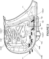
- FIG. 3 is a side view of the internal bonnet panel 110B from above showing the first flow path F1 of air through the left-hand bonnet air conduit 110C.
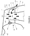
- FIG. 4 is a cross-sectional view of a portion of the vehicle along line X-X of FIG. 3 . It can be seen from FIG. 4 that the intake aperture members or intake turrets 152, 152' are coupled to respective left and right structural members 125 of the vehicle to which left and right wing panels 120 are also coupled. Left and right front suspension struts are also coupled to the respective left and right support members 125.
- the bonnet 110 is of the clamshell type, having a downwardly depending lip 110L provided around an outer peripheral edge of the bonnet 110. With the bonnet 110 in a closed condition a gap 120G is provided between a lower edge of the lip 110L and the body. In the present embodiment the gap is around 6mm in width although other arrangements are also useful. It is to be understood that other bonnet types are also useful.
- a convergence volume or region 150C, 150C' Inboard of the lip 110L of the bonnet 110 but outboard of the engine compartment 105, above the intake turrets 152, 152' is provided a convergence volume or region 150C, 150C'. Air drawn through respective air conduits 110C, 110C' is drawn into the convergence region 150C, 150C' and subsequently through a respective intake aperture member 152, 152'.
- air may also be drawn into the convergence regions 150C, 150C' and thereby into respective intake turrets 152, 152' through the gap 120G between the bonnet 110 and respective left and right wing panels 120. That is, a leak path exists for air into the intake turrets 152, 152' from around the intake turrets 152, 152' and not just from the bonnet air conduits 110C, 110C'.
- a flow path of air may be referred to as a second flow path and is illustrated by arrows F2 in FIG. 2 and FIG. 4 .
- the convergence regions 150C, 150C' are therefore regions in which an air flow path through a respective bonnet air conduit 110C, 110C' converges with an air flow path through a gap 120G between the bonnet 110 and a respective left and right wing panel 120.
- the presence of the second flow path has the advantage that if the conduits 110C, 110C' become blocked, for example by immersion in water during a wading operation, air may still be supplied to the convergence regions 150C, 150C'.
- the conduits 110C, 110C' may become blocked for example when the vehicle enters water nose first, such that a front portion of the bonnet 110 becomes submerged in water.
- the precise location of the convergence regions 150C, 150C' may be determined to meet requirements in respect of packaging of one or more components of the air duct assembly 150 and factors such as a maximum wading depth and maximum angle of entry of the vehicle into water, so as to prevent ingress of water into the intake turrets 152, 152' during wading operations. Other arrangements are also useful.
- the intake turrets 152, 152' protrude upwardly above their respective support members 125 such that air flowing through the gap 120G towards one of the convergence regions 150C, 150C' is forced to rise upwardly above the support member 125 before entering the respective convergence region 150C, 150C'.
- This feature has the advantage of reducing a risk that particles entrained in the flow of air through the gap 120G are drawn through the intake turrets 152, 152' and thereby into the intake duct assembly 150. Rather, it is found that entrained particles such as water droplets and snow flakes are instead blown rearwardly away from the inlet aperture members 152, 152' before the particles are able to pass through an inlet aperture member 152, 152'.
- water droplets and snow flakes are prevented from accumulating around the intake turrets 152, 152' thereby blocking the second flowpath of air to the intake turrets 152, 152'.
- a vertical gap exists between the bonnet air conduit outlet apertures 110OUT, 110OUT' and intake turrets 152, 152', whereby air travelling along the first flow path is required to exit a bonnet air conduit 110C, 110C' before entering an intake aperture member 152, 152'.
- the intake turrets 152, 152' are arranged to protrude upwardly into the air outlet apertures 110OUT, 110OUT' of the respective bonnet air conduits 110C, 110C'.
- the intake turrets 152, 152' protrude upwardly into the bonnet air conduit outlet apertures 110OUT, 110OUT' substantially as shown in dashed outline at 152H in FIG. 4 .
- the height of the intake turrets 152, 152' may be selected so as to obtain a desired balance of air flow through the turrets 152, 152' along the first and second flow paths F1, F2 respectively.
- the convergence regions 150C, 150C' may be provided at least partially within the respective air conduits 150C, 150C'. This feature has the advantage of further reducing a risk that any droplets of water or flakes of snow entrained in intake air are drawn through an intake aperture member 152, 152' and into the air duct assembly 150.
- the support member 125 is provided with a baffle wall 125B along an inboard edge thereof.
- the baffle wall 125B rises to meet the bonnet 110 when the bonnet 110 is in the closed position.
- a seal member 110S is provided between the internal panel 110B of the bonnet 110 and the baffle wall 125B. The purpose of the seal member 110S is to prevent flow of air from the engine compartment 105 into the convergence region 150C, 150C'. Air within the engine compartment 105 is therefore prevented from entering the intake duct assembly 150. Thus only relatively cool ambient air is able to enter the intake duct assembly 150.
- a gap 120G is provided between the bonnet 110 and a wing panel 120 of the vehicle.
- the gap 120G is sufficiently wide to allow ambient air to be drawn through the gap 120G and into a convergence region 150C, 150C'.
- the gap 120G is sufficiently wide to prevent water such as rainwater from blocking the gap 120G when the vehicle is operating in wet conditions.
- the gap 120G is sufficiently wide that rainwater flowing over the bonnet 110 across the gap 120G does not prevent air from being drawn through the gap 120G.
- the gap 120G is also of a width sufficiently large to reduce a risk that excessive amounts of rainwater are drawn into a convergence region 150C, 150C' by the flow of air through the gap 120G.
- FIG. 5 is plan view of a front left portion of a vehicle 100 according to an embodiment of the invention of which portions are shown in FIG. 1 to 4 .
- the external panel 110A ( FIG. 1 ) of the bonnet 110 of the vehicle 100 has been removed in order to expose the internal panel 110B.
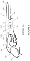
- FIG. 6 is a cross-sectional view of the front portion of the vehicle 100 along line A-A of FIG. 5 .
- the air inlets 110IN of the bonnet 110 are provided immediately aft of a left-hand lighting cluster 107 of the vehicle 100.
- the right hand front portion of the vehicle 100 (not shown in FIG. 5 ) is arranged in a substantially symmetrical manner in so far as the air inlets 110IN and lighting cluster 107 are concerned.
- the air inlets 110IN, 110IN' may be arranged to draw air through a front grille 106 of the vehicle 100 in addition to or instead of through a gap between the bonnet and a lighting cluster.
- the front grille may be a central front grille 106 arranged to direct ram air through a radiator pack of the vehicle 100.
- Other grille arrangements are also useful.
- the air inlets 110IN, 110IN' may be arranged to draw air through a respective dedicated one or more grilles.
- a grille through which air may be supplied to an air inlet 110IN, 110IN' may be arranged to direct air specifically towards an air inlet 110IN, 110IN'.
- a grille may be arranged to direct at least a portion of air flowing through the grille towards an air inlet 110IN, 110IN'.
- an upper region or portion of a grille may be arranged to direct air into an air inlet 110IN, 110IN'.
- the grille may be arranged to direct substantially all of the air flowing through the grille into an air inlet 110IN, 110IN'.
- a grille may be arranged to deflect air in an upward direction to an air inlet 110IN, 110IN'.
- the bonnet is provided with a sound reducing portion in the form of a Helmholtz resonator arrangement.
- the Helmholtz resonator arrangement may be configured to dampen sound associated with passage of air along the first flow path through the bonnet air conduits 110C, 110C'.
- a resonator cavity is defined by the external and internal bonnet panels 110A, 110B thereby to absorb acoustic energy created by flow of air along the first flow path. Other arrangements are also useful.
- embodiments of the present invention have the advantage that air may be drawn into an air intake duct arrangement 150 from a plurality of air sources without a requirement to provide an aperture in one or more external panels of the vehicle 100. Rather, air may be drawn into the intake duct arrangement 150 through a gap 120G between the bonnet 110 and a body of the vehicle 100 such as a gap 120G between the bonnet 110 and a wing panel or a gap 120G between the bonnet 110 and a lighting cluster 107.
- Some embodiments of the present invention have the advantage that a styling of a vehicle may be designed without a requirement to incorporate engine air intake duct apertures in one or more panels of the vehicle such as a bonnet, a wing, a bumper fascia or any other panel. Furthermore, some embodiments of the invention have the advantage that an engine intake air assembly may be provided with an intake orifice that is arranged to draw intake air from a relatively high position below a bonnet of the vehicle. Thus a maximum depth of water in which a vehicle may wade may be increased relative to known intake air orifice locations.
Landscapes
- Engineering & Computer Science (AREA)
- Mechanical Engineering (AREA)
- Chemical & Material Sciences (AREA)
- Combustion & Propulsion (AREA)
- Transportation (AREA)
- General Engineering & Computer Science (AREA)
- Physics & Mathematics (AREA)
- Acoustics & Sound (AREA)
- Superstructure Of Vehicle (AREA)
- Cooling, Air Intake And Gas Exhaust, And Fuel Tank Arrangements In Propulsion Units (AREA)
Claims (12)
- Kraftfahrzeug (100), Folgendes umfassend:eine Fahrzeugkarosserie;einen Motorraum (105), in dem sich ein Motor befindet;eine Motorhaube (110), bewegbar an die Karosserie gekoppelt und angeordnet, ein Verschlusselement für den Motorraum (105) bereitzustellen, wobei die Motorhaube (110) zwischen einem geöffneten und einem geschlossenen Zustand bewegbar ist, um Zugang zu dem Motorraum (105) bereitzustellen; undeinen Motoransaugkanal (150) mit einer Öffnung (152; 152'), durch die Ansaugluft in den Motor gesaugt werden kann,wobei das Fahrzeug mit einem ersten und einem zweiten Luftströmungspfad (F1, F2) versehen ist, durch die Luft des Ansaugkanals (150) zugeführt wird,wobei der erste Strömungspfad (F1) Folgendes umfasst: eine Lufteinlassöffnung (110IN; 110IN'), angeordnet in einem vorderen Abschnitt des Fahrzeugs, um Stauluft aufzunehmen, und eine Luftauslassöffnung (110OUT; 110OUT') hinter der Lufteinlassöffnung (110IN; 110IN'), wobei die Luftauslassöffnung (110OUT; 110OUT') in Fluidkommunikation mit der Ansaugkanalöffnung (152; 152') bereitgestellt ist;wobei der zweite Strömungspfad (F2) mit einem Spalt (120G) zwischen einer Seitenkante der Motorhaube (110) und der Karosserie des Fahrzeugs versehen ist, wodurch vergleichsweise kühle Umgebungsluft durch den Spalt (120G) zum Ansaugkanal (150) gesogen werden kann.
- Fahrzeug nach Anspruch 1, wobei der erste Strömungspfad durch eine Motorhauben-Ansaugleitung (110C; 110C') bereitgestellt ist, wobei die Lufteinlassöffnung (110IN; 110IN') an einem vorderen Abschnitt der Motorhaube (110) bereitgestellt ist.
- Fahrzeug nach Anspruch 2, wobei der Lufteinlass (110IN; 110IN') der Motorhauben-Ansaugleitung (110C; 110C') angeordnet ist, Luft, die durch einen Spalt zwischen der Motorhaube (110) und einem vorderen Abschnitt der Fahrzeugkarosserie strömt, zu saugen, optional wobei der vordere Abschnitt der Fahrzeugkarosserie eine vordere Scheinwerfereinheit (107) ist.
- Fahrzeug nach Anspruch 2 oder 3, versehen mit einem Kühlergrill (106) zum Empfangen von Stauluft während der Fahrt in einer Vorwärtsrichtung, wobei der Lufteinlass (110IN; 110IN') der Motorhauben-Ansaugleitung (110C; 110C') in Fluidkommunikation mit durch den Kühlergrill (106) empfangener Luft steht, optional wobei das Fahrzeug angeordnet ist, wenigstens einen Teil von durch den Kühlergrill (106) strömender Stauluft nach oben in den Lufteinlass (110IN; 110IN') der Motorhauben-Ansaugleitung (110C; 110C') umzuleiten.
- Fahrzeug nach einem der Ansprüche 2 bis 4, wobei die Ansaugöffnung (152; 152') des Motoransaugkanals (150) angeordnet ist, in einer Richtung im Wesentlichen nach oben zu weisen, um somit von dem Motorhauben-Ansaugkanal (110C; 110C') nach unten strömende Luft zu empfangen, wobei ein Leckpfad zwischen der Motorhauben-Ansaugleitungsauslassöffnung (110OUT; 110OUT') und der Ansaugöffnung (152; 152') bereitgestellt wird, wodurch ermöglicht wird, dass Luft den zweiten Strömungspfad (F2) entlang strömt, um durch die Ansaugöffnung (152; 152') zu strömen.
- Fahrzeug nach einem der Ansprüche 2 bis 5, wobei die Motoransaugöffnung (152; 152') definiert ist durch ein Motoransaugöffnungselement, wobei das Ansaugöffnungselement angeordnet ist, wobei die Luft, die den zweiten Strömungspfad (F2) entlang strömt, und die durch den Spalt (120G) zwischen der Seitenkante der Motorhaube (110) und der Fahrzeugkarosserie geströmt ist, aufsteigen muss, bevor sie durch die Öffnung (152; 152') gesaugt wird.
- Fahrzeug nach Anspruch 6, wobei das Ansaugöffnungselement angeordnet ist, nach oben in die Motorhauben-Luftleitungsauslassöffnung (110OUT; 110OUT') zu ragen, wodurch Luft, die den zweiten Strömungspfad (F2) entlang strömt, durch die Motorhauben-Luftleitungsauslassöffnung (110OUT; 110OUT') strömen muss, bevor sie in das Ansaugöffnungselement (152; 152') strömt.
- Fahrzeug nach einem der Ansprüche 2 bis 7, wobei die Motoransaugöffnung (152; 152') fluidisch von dem Motorraum isoliert bereitgestellt ist, optional wobei ein Dichtmittel (110S) an einer Stelle zwischen der Ansaugöffnung (152; 152') und dem Motorraum (105) bereitgestellt ist, um somit einen Luftstrom von dem Motorraum (105) hin zu der Ansaugöffnung (152; 152') bereitzustellen.
- Fahrzeug nach einem der Ansprüche 2 bis 8, wobei die Motorhauben-Ansaugleitung (110C; 110C') durch eine externe beziehungsweise interne Platte (110A, 110B) der Motorhaube definiert ist, wobei die externe und die interne Platte (110A, 110B) aneinander gekoppelt sind, um somit die Leitung (110C; 110C') dazwischen zu definieren, optional wobei der Lufteinlass (110IN; 110IN') der Motorhauben-Ansaugleitung und der Luftauslass (110OUT; 110OUT') der Motorhauben-Ansaugleitung durch die interne Platte (110B) definiert sind.
- Fahrzeug nach einem der Ansprüche 2 bis 9, umfassend ein Paar Ansaugkanalöffnungen (152, 152'), angeordnet auf jeweiligen einander gegenüberliegenden Seiten des Motorraums (105), wobei die Motorhaube (110) ein entsprechendes Paar aus Motorhauben-Ansaugleitungen (110C, 110C') bereitstellt.
- Fahrzeug nach einem der vorhergehenden Ansprüche, wobei die Motorhaube (110) eine Klapp-Motorhaube ist.
- Verfahren zum Bereitstellen von Ansaugluft an einen Motor eines Kraftfahrzeugs (100), Folgendes umfassend:Saugen von Luft in einen Motor über eine Öffnung (152; 152') eines Ansaugkanals (150) entlang eines ersten und eines zweiten Strömungspfads (F1, F2),wodurch Luft, die den ersten Strömungspfad (F1) entlang strömt, durch eine Ansaugleitung (110C; 110C') einer Motorhaube (110) des Fahrzeugs strömt, wobei die Motorhauben-Ansaugleitung (110C; 110C') eine Lufteinlassöffnung (110IN; 110IN') in einem vorderen Abschnitt der Motorhaube (110) und eine Luftauslassöffnung (110OUT; 110OUT') hinter der Lufteinlassöffnung (110IN; 110IN') aufweist, durch die Luft gesaugt wird, wobei sich die Luftauslassöffnung (110OUT; 110OUT') in Fluidverbindung mit der Ansaugkanalöffnung (152; 152') befindet,und wobei Fluid, das den zweiten Strömungspfad (F2) entlang strömt, angeordnet ist, durch einen Spalt (120G) zwischen einer Seitenkante der Motorhaube (110) und der Karosserie des Fahrzeugs (100) zu strömen, wodurch vergleichsweise kühle Umgebungsluft durch den Spalt (120G) zur Ansaugleitung (150) gesogen werden kann.
Applications Claiming Priority (2)
| Application Number | Priority Date | Filing Date | Title |
|---|---|---|---|
| GB1200938.7A GB2497143B (en) | 2012-01-20 | 2012-01-20 | Motor vehicle with improved air intake apparatus |
| PCT/EP2013/051029 WO2013107903A1 (en) | 2012-01-20 | 2013-01-21 | Motor vehicle with improved air intake apparatus |
Publications (2)
| Publication Number | Publication Date |
|---|---|
| EP2807364A1 EP2807364A1 (de) | 2014-12-03 |
| EP2807364B1 true EP2807364B1 (de) | 2017-05-03 |
Family
ID=45814266
Family Applications (1)
| Application Number | Title | Priority Date | Filing Date |
|---|---|---|---|
| EP13703742.0A Active EP2807364B1 (de) | 2012-01-20 | 2013-01-21 | Kraftfahrzeug mit verbesserter lufteinlassvorrichtung |
Country Status (6)
| Country | Link |
|---|---|
| US (1) | US9545844B2 (de) |
| EP (1) | EP2807364B1 (de) |
| JP (1) | JP6072074B2 (de) |
| CN (1) | CN104066963B (de) |
| GB (2) | GB2497143B (de) |
| WO (1) | WO2013107903A1 (de) |
Families Citing this family (33)
| Publication number | Priority date | Publication date | Assignee | Title |
|---|---|---|---|---|
| DE102012110923B4 (de) * | 2012-11-14 | 2017-10-19 | Dr. Ing. H.C. F. Porsche Aktiengesellschaft | Luftzuführung |
| KR101509703B1 (ko) * | 2013-10-10 | 2015-04-07 | 현대자동차 주식회사 | 자동차의 에어 클리너 |
| GB2529241A (en) * | 2014-08-15 | 2016-02-17 | Jaguar Land Rover Ltd | Air intake apparatus |
| WO2016126187A1 (en) * | 2015-02-02 | 2016-08-11 | China-Euro Vehicle Technology Aktiebolag | Air intake |
| JP6311690B2 (ja) * | 2015-10-26 | 2018-04-18 | マツダ株式会社 | 車両の前部構造 |
| CN108367670B (zh) * | 2015-12-11 | 2021-08-03 | 沃尔沃卡车集团 | 用于卡车、牵引车或公交车辆的主动式燃烧空气进气系统 |
| US9764776B2 (en) * | 2015-12-18 | 2017-09-19 | Honda Motor Co., Ltd. | Motor vehicle engine room air and water management system |
| DE102016116701B4 (de) * | 2016-09-07 | 2024-09-12 | Dr. Ing. H.C. F. Porsche Aktiengesellschaft | Seitenbauteil und Fahrzeug mit einem Seitenbauteil |
| US10280879B2 (en) | 2016-09-09 | 2019-05-07 | Fca Us Llc | Snorkel and pressure relief valve for dual path cool air inlet system |
| US10012186B2 (en) | 2016-09-09 | 2018-07-03 | Fca Us Llc | Ram air power valve |
| CN110198857A (zh) * | 2017-01-10 | 2019-09-03 | 福特全球技术公司 | 车辆进气歧管系统 |
| US10330057B2 (en) * | 2017-01-30 | 2019-06-25 | Ford Global Technologies, Llc | Hood insulator having an integral air box closeout feature |
| US20180354355A1 (en) * | 2017-06-12 | 2018-12-13 | Paccar Inc | Air ducts for airflow management, and associated systems and methods |
| JP6549642B2 (ja) * | 2017-06-14 | 2019-07-24 | 本田技研工業株式会社 | 車両の吸気構造 |
| US10393076B1 (en) * | 2018-08-30 | 2019-08-27 | Toyota Motor North America, Inc. | Tethered air intake snorkel |
| GB2579181B (en) * | 2018-11-21 | 2021-10-20 | Jaguar Land Rover Ltd | A vehicle bonnet, a method of assembling a vehicle bonnet and a vehicle comprising a bonnet |
| CN110104073B (zh) * | 2019-05-07 | 2020-12-04 | 绍兴不忘初心机械设计有限公司 | 一种防掀起的汽车引擎盖 |
| US11292333B2 (en) | 2019-06-04 | 2022-04-05 | Fca Us Llc | Snow accumulation prevention for air induction system |
| KR102751056B1 (ko) * | 2019-12-16 | 2025-01-08 | 현대자동차주식회사 | 능동형 에어커튼 장치 및 능동형 에어커튼 시스템 |
| USD1031782S1 (en) | 2020-02-09 | 2024-06-18 | Velossa Tech Engineering, Inc. | Ram-air intake |
| USD1019704S1 (en) | 2020-02-09 | 2024-03-26 | Velossa Tech Engineering, Inc. | Ram-air intake |
| USD1023061S1 (en) | 2020-02-09 | 2024-04-16 | Velossa Tech Engineering, Inc. | Ram-air intake |
| US12180916B2 (en) | 2020-02-09 | 2024-12-31 | Velossa Tech Engineering Inc. | Interchangeable intake manifold assemblies |
| CN114248847B (zh) * | 2020-09-22 | 2024-08-30 | 陕西汽车集团股份有限公司 | 一种具备模块化消声功能的机舱盖 |
| US11655752B2 (en) | 2021-09-30 | 2023-05-23 | Ford Global Technologies, Llc | Water separator to slow water ingestion |
| US11536230B1 (en) | 2021-10-26 | 2022-12-27 | Ford Global Technologies, Llc | Charge-air cooler and water distribution device to evenly proved water to engine cylinders |
| US12485989B2 (en) | 2022-02-15 | 2025-12-02 | Arctic Cat Inc. | Headlight assembly |
| US12208854B2 (en) | 2022-02-15 | 2025-01-28 | Arctic Cat Inc. | Snowmobile frame |
| US12503200B2 (en) | 2022-02-16 | 2025-12-23 | Arctic Cat Inc. | Recoil housing, engine assembly, and method of assembling engine assembly |
| US11891941B2 (en) | 2022-03-09 | 2024-02-06 | Honda Motor Co., Ltd. | Fluid flow management in vehicles |
| US11698037B1 (en) | 2022-04-08 | 2023-07-11 | Ford Global Technologies, Llc | Fuel system for a vehicle and method of controlling |
| USD1082637S1 (en) | 2023-03-07 | 2025-07-08 | Arctic Cat Inc. | Running board for a snow vehicle |
| USD1063697S1 (en) | 2023-03-07 | 2025-02-25 | Arctic Cat Inc. | Rear kick-up for a snow vehicle |
Citations (1)
| Publication number | Priority date | Publication date | Assignee | Title |
|---|---|---|---|---|
| JPH0221122U (de) * | 1988-07-29 | 1990-02-13 |
Family Cites Families (24)
| Publication number | Priority date | Publication date | Assignee | Title |
|---|---|---|---|---|
| US2881860A (en) | 1955-04-11 | 1959-04-14 | William A Ternes | Air cleaner and silencer |
| US3641746A (en) * | 1969-09-08 | 1972-02-15 | Chrysler Corp | Carburetor air delivery system |
| FR2536719B1 (fr) * | 1982-11-25 | 1987-05-15 | Peugeot | Capot pour compartiment moteur de vehicule automobile |
| JPS62110024U (de) * | 1985-12-28 | 1987-07-14 | ||
| DE8715030U1 (de) * | 1987-11-12 | 1988-01-21 | Audi AG, 8070 Ingolstadt | Kraftfahrzeug |
| JPH049329U (de) * | 1990-05-16 | 1992-01-28 | ||
| US5195484A (en) | 1991-10-24 | 1993-03-23 | General Motors Corporation | Air cleaner and snorkel assembly |
| US5134977A (en) * | 1991-12-23 | 1992-08-04 | Ford Motor Company | Engine air cleaner inlet tube for automotive engine |
| US5199522A (en) * | 1992-05-27 | 1993-04-06 | Ford New Holland, Inc. | Air inlet for vehicle engine |
| JP2830788B2 (ja) * | 1995-08-25 | 1998-12-02 | トヨタ自動車株式会社 | エンジンルーム内の吸気冷却構造 |
| JP2856122B2 (ja) | 1995-09-29 | 1999-02-10 | トヨタ自動車株式会社 | エンジンルーム内の吸気冷却構造 |
| JPH09136551A (ja) * | 1995-11-16 | 1997-05-27 | Fuji Heavy Ind Ltd | エンジンの吸気装置 |
| DE10049282B4 (de) * | 1999-10-01 | 2007-10-18 | Mtd Products Inc., Valley City | Luftansaugsystem |
| US6425930B1 (en) * | 2000-08-31 | 2002-07-30 | International Truck Intellectual Property Company, L.L.C. | Air cleaner with self-mounted inlet shroud seal |
| JP3801475B2 (ja) * | 2001-09-21 | 2006-07-26 | 株式会社クボタ | 芝刈り機の冷却用空気取り入れ構造 |
| JP2004301671A (ja) * | 2003-03-31 | 2004-10-28 | Toshiba Corp | 回転機の軸受診断システム、回転機の軸受診断装置及び回転機のスタッド |
| US7237635B2 (en) * | 2004-07-12 | 2007-07-03 | Honda Motor Co., Ltd. | Automobile over-bulkhead air intake system |
| JP4609058B2 (ja) * | 2004-12-09 | 2011-01-12 | 株式会社デンソー | 内燃機関用吸気装置 |
| FR2886892A1 (fr) * | 2005-06-09 | 2006-12-15 | Renault Sas | Dispositif d'alimentation en air d'un moteur de vehicule |
| WO2008055216A2 (en) | 2006-10-31 | 2008-05-08 | Enviro-Cool, Inc. | Air management system for truck |
| JP4333747B2 (ja) * | 2007-01-29 | 2009-09-16 | トヨタ自動車株式会社 | 車両用内燃機関の吸気装置 |
| JP2008247122A (ja) * | 2007-03-29 | 2008-10-16 | Mazda Motor Corp | 車体前部構造 |
| JP5131037B2 (ja) * | 2008-06-06 | 2013-01-30 | 日産自動車株式会社 | 外気導入ダクト及びその取付構造 |
| JP2010048234A (ja) * | 2008-08-25 | 2010-03-04 | Toyota Boshoku Corp | 吸気ダクト |
-
2012
- 2012-01-20 GB GB1200938.7A patent/GB2497143B/en not_active Expired - Fee Related
-
2013
- 2013-01-21 WO PCT/EP2013/051029 patent/WO2013107903A1/en not_active Ceased
- 2013-01-21 GB GB1301004.6A patent/GB2499506B/en active Active
- 2013-01-21 EP EP13703742.0A patent/EP2807364B1/de active Active
- 2013-01-21 JP JP2014552649A patent/JP6072074B2/ja not_active Expired - Fee Related
- 2013-01-21 US US14/372,880 patent/US9545844B2/en active Active
- 2013-01-21 CN CN201380006001.0A patent/CN104066963B/zh not_active Expired - Fee Related
Patent Citations (1)
| Publication number | Priority date | Publication date | Assignee | Title |
|---|---|---|---|---|
| JPH0221122U (de) * | 1988-07-29 | 1990-02-13 |
Also Published As
| Publication number | Publication date |
|---|---|
| CN104066963A (zh) | 2014-09-24 |
| GB2499506B (en) | 2015-03-25 |
| JP2015505521A (ja) | 2015-02-23 |
| CN104066963B (zh) | 2017-05-03 |
| WO2013107903A1 (en) | 2013-07-25 |
| US20150202955A1 (en) | 2015-07-23 |
| US9545844B2 (en) | 2017-01-17 |
| EP2807364A1 (de) | 2014-12-03 |
| JP6072074B2 (ja) | 2017-02-01 |
| GB2499506A (en) | 2013-08-21 |
| GB2497143B (en) | 2014-07-30 |
| GB2497143A (en) | 2013-06-05 |
| GB201200938D0 (en) | 2012-02-29 |
| GB201301004D0 (en) | 2013-03-06 |
Similar Documents
| Publication | Publication Date | Title |
|---|---|---|
| EP2807364B1 (de) | Kraftfahrzeug mit verbesserter lufteinlassvorrichtung | |
| EP2169210B1 (de) | Motoreinlass-Durchlaufstruktur eines vorderen Fahrzeugkörpers und Verfahren zu deren Bereitstellung | |
| EP2678180B1 (de) | Lufteinlasssystem über einem schott | |
| EP2684718B1 (de) | Luftzufuhranordnung | |
| CN110461688A (zh) | 车辆的前部车身结构 | |
| US20130248141A1 (en) | Ducting arrangement and method for directing airflow toward a radiator | |
| EP2824001B1 (de) | Luftführungsstruktur | |
| WO2018127369A1 (en) | Motor vehicle bonnet seal arrangement | |
| US20130200655A1 (en) | Front end structure for vehicle | |
| CN109774425B (zh) | 车辆部件 | |
| JP4935240B2 (ja) | 車体前部構造 | |
| US11225137B1 (en) | Vehicle air induction assembly | |
| JP5338230B2 (ja) | 車体前部の走行風導入構造 | |
| JP6090188B2 (ja) | 自動車の前部構造 | |
| JP2008049815A (ja) | 車体前部構造 | |
| JP2018103840A (ja) | 車体構造 | |
| JP6308269B2 (ja) | 車両のカウル構造 | |
| JP6123692B2 (ja) | 自動車の前部構造 | |
| US20180362091A1 (en) | Front side member | |
| CN222987935U (zh) | 空调进气结构和车辆 | |
| JP6328687B2 (ja) | 車両のラジエーターサポートカバー | |
| JP6308272B2 (ja) | 車両のカウル構造 | |
| JP6308270B2 (ja) | 車両のカウル構造 | |
| JP6308271B2 (ja) | 車両のカウル構造 | |
| CN121345695A (zh) | 发动机进气结构及汽车 |
Legal Events
| Date | Code | Title | Description |
|---|---|---|---|
| PUAI | Public reference made under article 153(3) epc to a published international application that has entered the european phase |
Free format text: ORIGINAL CODE: 0009012 |
|
| 17P | Request for examination filed |
Effective date: 20140820 |
|
| AK | Designated contracting states |
Kind code of ref document: A1 Designated state(s): AL AT BE BG CH CY CZ DE DK EE ES FI FR GB GR HR HU IE IS IT LI LT LU LV MC MK MT NL NO PL PT RO RS SE SI SK SM TR |
|
| DAX | Request for extension of the european patent (deleted) | ||
| 17Q | First examination report despatched |
Effective date: 20151103 |
|
| GRAP | Despatch of communication of intention to grant a patent |
Free format text: ORIGINAL CODE: EPIDOSNIGR1 |
|
| INTG | Intention to grant announced |
Effective date: 20161214 |
|
| GRAS | Grant fee paid |
Free format text: ORIGINAL CODE: EPIDOSNIGR3 |
|
| GRAA | (expected) grant |
Free format text: ORIGINAL CODE: 0009210 |
|
| AK | Designated contracting states |
Kind code of ref document: B1 Designated state(s): AL AT BE BG CH CY CZ DE DK EE ES FI FR GB GR HR HU IE IS IT LI LT LU LV MC MK MT NL NO PL PT RO RS SE SI SK SM TR |
|
| REG | Reference to a national code |
Ref country code: GB Ref legal event code: FG4D |
|
| REG | Reference to a national code |
Ref country code: AT Ref legal event code: REF Ref document number: 890287 Country of ref document: AT Kind code of ref document: T Effective date: 20170515 Ref country code: CH Ref legal event code: EP |
|
| REG | Reference to a national code |
Ref country code: IE Ref legal event code: FG4D |
|
| REG | Reference to a national code |
Ref country code: DE Ref legal event code: R096 Ref document number: 602013020555 Country of ref document: DE |
|
| REG | Reference to a national code |
Ref country code: NL Ref legal event code: MP Effective date: 20170503 |
|
| REG | Reference to a national code |
Ref country code: AT Ref legal event code: MK05 Ref document number: 890287 Country of ref document: AT Kind code of ref document: T Effective date: 20170503 |
|
| REG | Reference to a national code |
Ref country code: LT Ref legal event code: MG4D |
|
| PG25 | Lapsed in a contracting state [announced via postgrant information from national office to epo] |
Ref country code: NO Free format text: LAPSE BECAUSE OF FAILURE TO SUBMIT A TRANSLATION OF THE DESCRIPTION OR TO PAY THE FEE WITHIN THE PRESCRIBED TIME-LIMIT Effective date: 20170803 Ref country code: GR Free format text: LAPSE BECAUSE OF FAILURE TO SUBMIT A TRANSLATION OF THE DESCRIPTION OR TO PAY THE FEE WITHIN THE PRESCRIBED TIME-LIMIT Effective date: 20170804 Ref country code: AT Free format text: LAPSE BECAUSE OF FAILURE TO SUBMIT A TRANSLATION OF THE DESCRIPTION OR TO PAY THE FEE WITHIN THE PRESCRIBED TIME-LIMIT Effective date: 20170503 Ref country code: HR Free format text: LAPSE BECAUSE OF FAILURE TO SUBMIT A TRANSLATION OF THE DESCRIPTION OR TO PAY THE FEE WITHIN THE PRESCRIBED TIME-LIMIT Effective date: 20170503 Ref country code: LT Free format text: LAPSE BECAUSE OF FAILURE TO SUBMIT A TRANSLATION OF THE DESCRIPTION OR TO PAY THE FEE WITHIN THE PRESCRIBED TIME-LIMIT Effective date: 20170503 Ref country code: ES Free format text: LAPSE BECAUSE OF FAILURE TO SUBMIT A TRANSLATION OF THE DESCRIPTION OR TO PAY THE FEE WITHIN THE PRESCRIBED TIME-LIMIT Effective date: 20170503 Ref country code: FI Free format text: LAPSE BECAUSE OF FAILURE TO SUBMIT A TRANSLATION OF THE DESCRIPTION OR TO PAY THE FEE WITHIN THE PRESCRIBED TIME-LIMIT Effective date: 20170503 |
|
| PG25 | Lapsed in a contracting state [announced via postgrant information from national office to epo] |
Ref country code: IS Free format text: LAPSE BECAUSE OF FAILURE TO SUBMIT A TRANSLATION OF THE DESCRIPTION OR TO PAY THE FEE WITHIN THE PRESCRIBED TIME-LIMIT Effective date: 20170903 Ref country code: NL Free format text: LAPSE BECAUSE OF FAILURE TO SUBMIT A TRANSLATION OF THE DESCRIPTION OR TO PAY THE FEE WITHIN THE PRESCRIBED TIME-LIMIT Effective date: 20170503 Ref country code: LV Free format text: LAPSE BECAUSE OF FAILURE TO SUBMIT A TRANSLATION OF THE DESCRIPTION OR TO PAY THE FEE WITHIN THE PRESCRIBED TIME-LIMIT Effective date: 20170503 Ref country code: RS Free format text: LAPSE BECAUSE OF FAILURE TO SUBMIT A TRANSLATION OF THE DESCRIPTION OR TO PAY THE FEE WITHIN THE PRESCRIBED TIME-LIMIT Effective date: 20170503 Ref country code: PL Free format text: LAPSE BECAUSE OF FAILURE TO SUBMIT A TRANSLATION OF THE DESCRIPTION OR TO PAY THE FEE WITHIN THE PRESCRIBED TIME-LIMIT Effective date: 20170503 Ref country code: SE Free format text: LAPSE BECAUSE OF FAILURE TO SUBMIT A TRANSLATION OF THE DESCRIPTION OR TO PAY THE FEE WITHIN THE PRESCRIBED TIME-LIMIT Effective date: 20170503 Ref country code: BG Free format text: LAPSE BECAUSE OF FAILURE TO SUBMIT A TRANSLATION OF THE DESCRIPTION OR TO PAY THE FEE WITHIN THE PRESCRIBED TIME-LIMIT Effective date: 20170803 |
|
| REG | Reference to a national code |
Ref country code: FR Ref legal event code: PLFP Year of fee payment: 6 |
|
| PG25 | Lapsed in a contracting state [announced via postgrant information from national office to epo] |
Ref country code: DK Free format text: LAPSE BECAUSE OF FAILURE TO SUBMIT A TRANSLATION OF THE DESCRIPTION OR TO PAY THE FEE WITHIN THE PRESCRIBED TIME-LIMIT Effective date: 20170503 Ref country code: RO Free format text: LAPSE BECAUSE OF FAILURE TO SUBMIT A TRANSLATION OF THE DESCRIPTION OR TO PAY THE FEE WITHIN THE PRESCRIBED TIME-LIMIT Effective date: 20170503 Ref country code: SK Free format text: LAPSE BECAUSE OF FAILURE TO SUBMIT A TRANSLATION OF THE DESCRIPTION OR TO PAY THE FEE WITHIN THE PRESCRIBED TIME-LIMIT Effective date: 20170503 Ref country code: EE Free format text: LAPSE BECAUSE OF FAILURE TO SUBMIT A TRANSLATION OF THE DESCRIPTION OR TO PAY THE FEE WITHIN THE PRESCRIBED TIME-LIMIT Effective date: 20170503 Ref country code: CZ Free format text: LAPSE BECAUSE OF FAILURE TO SUBMIT A TRANSLATION OF THE DESCRIPTION OR TO PAY THE FEE WITHIN THE PRESCRIBED TIME-LIMIT Effective date: 20170503 |
|
| REG | Reference to a national code |
Ref country code: DE Ref legal event code: R097 Ref document number: 602013020555 Country of ref document: DE |
|
| PG25 | Lapsed in a contracting state [announced via postgrant information from national office to epo] |
Ref country code: IT Free format text: LAPSE BECAUSE OF FAILURE TO SUBMIT A TRANSLATION OF THE DESCRIPTION OR TO PAY THE FEE WITHIN THE PRESCRIBED TIME-LIMIT Effective date: 20170503 Ref country code: SM Free format text: LAPSE BECAUSE OF FAILURE TO SUBMIT A TRANSLATION OF THE DESCRIPTION OR TO PAY THE FEE WITHIN THE PRESCRIBED TIME-LIMIT Effective date: 20170503 |
|
| PLBE | No opposition filed within time limit |
Free format text: ORIGINAL CODE: 0009261 |
|
| STAA | Information on the status of an ep patent application or granted ep patent |
Free format text: STATUS: NO OPPOSITION FILED WITHIN TIME LIMIT |
|
| 26N | No opposition filed |
Effective date: 20180206 |
|
| PG25 | Lapsed in a contracting state [announced via postgrant information from national office to epo] |
Ref country code: SI Free format text: LAPSE BECAUSE OF FAILURE TO SUBMIT A TRANSLATION OF THE DESCRIPTION OR TO PAY THE FEE WITHIN THE PRESCRIBED TIME-LIMIT Effective date: 20170503 |
|
| REG | Reference to a national code |
Ref country code: CH Ref legal event code: PL |
|
| PG25 | Lapsed in a contracting state [announced via postgrant information from national office to epo] |
Ref country code: LU Free format text: LAPSE BECAUSE OF NON-PAYMENT OF DUE FEES Effective date: 20180121 |
|
| REG | Reference to a national code |
Ref country code: IE Ref legal event code: MM4A |
|
| REG | Reference to a national code |
Ref country code: BE Ref legal event code: MM Effective date: 20180131 |
|
| PG25 | Lapsed in a contracting state [announced via postgrant information from national office to epo] |
Ref country code: LI Free format text: LAPSE BECAUSE OF NON-PAYMENT OF DUE FEES Effective date: 20180131 Ref country code: BE Free format text: LAPSE BECAUSE OF NON-PAYMENT OF DUE FEES Effective date: 20180131 Ref country code: CH Free format text: LAPSE BECAUSE OF NON-PAYMENT OF DUE FEES Effective date: 20180131 |
|
| PG25 | Lapsed in a contracting state [announced via postgrant information from national office to epo] |
Ref country code: IE Free format text: LAPSE BECAUSE OF NON-PAYMENT OF DUE FEES Effective date: 20180121 |
|
| PG25 | Lapsed in a contracting state [announced via postgrant information from national office to epo] |
Ref country code: MC Free format text: LAPSE BECAUSE OF FAILURE TO SUBMIT A TRANSLATION OF THE DESCRIPTION OR TO PAY THE FEE WITHIN THE PRESCRIBED TIME-LIMIT Effective date: 20170503 |
|
| PG25 | Lapsed in a contracting state [announced via postgrant information from national office to epo] |
Ref country code: MT Free format text: LAPSE BECAUSE OF NON-PAYMENT OF DUE FEES Effective date: 20180121 |
|
| PG25 | Lapsed in a contracting state [announced via postgrant information from national office to epo] |
Ref country code: TR Free format text: LAPSE BECAUSE OF FAILURE TO SUBMIT A TRANSLATION OF THE DESCRIPTION OR TO PAY THE FEE WITHIN THE PRESCRIBED TIME-LIMIT Effective date: 20170503 |
|
| PG25 | Lapsed in a contracting state [announced via postgrant information from national office to epo] |
Ref country code: PT Free format text: LAPSE BECAUSE OF FAILURE TO SUBMIT A TRANSLATION OF THE DESCRIPTION OR TO PAY THE FEE WITHIN THE PRESCRIBED TIME-LIMIT Effective date: 20170503 Ref country code: HU Free format text: LAPSE BECAUSE OF FAILURE TO SUBMIT A TRANSLATION OF THE DESCRIPTION OR TO PAY THE FEE WITHIN THE PRESCRIBED TIME-LIMIT; INVALID AB INITIO Effective date: 20130121 |
|
| PG25 | Lapsed in a contracting state [announced via postgrant information from national office to epo] |
Ref country code: MK Free format text: LAPSE BECAUSE OF NON-PAYMENT OF DUE FEES Effective date: 20170503 Ref country code: CY Free format text: LAPSE BECAUSE OF FAILURE TO SUBMIT A TRANSLATION OF THE DESCRIPTION OR TO PAY THE FEE WITHIN THE PRESCRIBED TIME-LIMIT Effective date: 20170503 |
|
| PG25 | Lapsed in a contracting state [announced via postgrant information from national office to epo] |
Ref country code: AL Free format text: LAPSE BECAUSE OF FAILURE TO SUBMIT A TRANSLATION OF THE DESCRIPTION OR TO PAY THE FEE WITHIN THE PRESCRIBED TIME-LIMIT Effective date: 20170503 |
|
| P01 | Opt-out of the competence of the unified patent court (upc) registered |
Effective date: 20230528 |
|
| PGFP | Annual fee paid to national office [announced via postgrant information from national office to epo] |
Ref country code: GB Payment date: 20260123 Year of fee payment: 14 |
|
| PGFP | Annual fee paid to national office [announced via postgrant information from national office to epo] |
Ref country code: DE Payment date: 20260121 Year of fee payment: 14 |
|
| PGFP | Annual fee paid to national office [announced via postgrant information from national office to epo] |
Ref country code: FR Payment date: 20260123 Year of fee payment: 14 |