EP2805835B1 - Pneumatic tire - Google Patents
Pneumatic tire Download PDFInfo
- Publication number
- EP2805835B1 EP2805835B1 EP13738284.2A EP13738284A EP2805835B1 EP 2805835 B1 EP2805835 B1 EP 2805835B1 EP 13738284 A EP13738284 A EP 13738284A EP 2805835 B1 EP2805835 B1 EP 2805835B1
- Authority
- EP
- European Patent Office
- Prior art keywords
- tire
- block
- polygonal
- circumferential
- groove
- Prior art date
- Legal status (The legal status is an assumption and is not a legal conclusion. Google has not performed a legal analysis and makes no representation as to the accuracy of the status listed.)
- Not-in-force
Links
- 239000011295 pitch Substances 0.000 description 32
- 238000006073 displacement reaction Methods 0.000 description 26
- 238000013461 design Methods 0.000 description 12
- 238000012360 testing method Methods 0.000 description 12
- 238000010586 diagram Methods 0.000 description 10
- 230000009467 reduction Effects 0.000 description 7
- 230000000052 comparative effect Effects 0.000 description 6
- 238000005096 rolling process Methods 0.000 description 6
- 230000000694 effects Effects 0.000 description 5
- 230000006872 improvement Effects 0.000 description 5
- 230000001154 acute effect Effects 0.000 description 3
- 230000008859 change Effects 0.000 description 3
- 238000006243 chemical reaction Methods 0.000 description 3
- 238000011161 development Methods 0.000 description 3
- 238000004458 analytical method Methods 0.000 description 2
- 230000006835 compression Effects 0.000 description 2
- 238000007906 compression Methods 0.000 description 2
- 230000002542 deteriorative effect Effects 0.000 description 2
- 238000011156 evaluation Methods 0.000 description 2
- 238000000034 method Methods 0.000 description 2
- 230000001629 suppression Effects 0.000 description 2
- XLYOFNOQVPJJNP-UHFFFAOYSA-N water Substances O XLYOFNOQVPJJNP-UHFFFAOYSA-N 0.000 description 2
- 230000001133 acceleration Effects 0.000 description 1
- 230000009471 action Effects 0.000 description 1
- 230000003321 amplification Effects 0.000 description 1
- 230000006866 deterioration Effects 0.000 description 1
- 238000003199 nucleic acid amplification method Methods 0.000 description 1
- 230000003252 repetitive effect Effects 0.000 description 1
- 238000010998 test method Methods 0.000 description 1
Images


Classifications
-
- B—PERFORMING OPERATIONS; TRANSPORTING
- B60—VEHICLES IN GENERAL
- B60C—VEHICLE TYRES; TYRE INFLATION; TYRE CHANGING; CONNECTING VALVES TO INFLATABLE ELASTIC BODIES IN GENERAL; DEVICES OR ARRANGEMENTS RELATED TO TYRES
- B60C11/00—Tyre tread bands; Tread patterns; Anti-skid inserts
- B60C11/03—Tread patterns
- B60C11/04—Tread patterns in which the raised area of the pattern consists only of continuous circumferential ribs, e.g. zig-zag
-
- B—PERFORMING OPERATIONS; TRANSPORTING
- B60—VEHICLES IN GENERAL
- B60C—VEHICLE TYRES; TYRE INFLATION; TYRE CHANGING; CONNECTING VALVES TO INFLATABLE ELASTIC BODIES IN GENERAL; DEVICES OR ARRANGEMENTS RELATED TO TYRES
- B60C11/00—Tyre tread bands; Tread patterns; Anti-skid inserts
- B60C11/03—Tread patterns
- B60C11/11—Tread patterns in which the raised area of the pattern consists only of isolated elements, e.g. blocks
-
- B—PERFORMING OPERATIONS; TRANSPORTING
- B60—VEHICLES IN GENERAL
- B60C—VEHICLE TYRES; TYRE INFLATION; TYRE CHANGING; CONNECTING VALVES TO INFLATABLE ELASTIC BODIES IN GENERAL; DEVICES OR ARRANGEMENTS RELATED TO TYRES
- B60C11/00—Tyre tread bands; Tread patterns; Anti-skid inserts
- B60C11/03—Tread patterns
- B60C2011/0337—Tread patterns characterised by particular design features of the pattern
- B60C2011/0339—Grooves
- B60C2011/0341—Circumferential grooves
- B60C2011/0346—Circumferential grooves with zigzag shape
-
- B—PERFORMING OPERATIONS; TRANSPORTING
- B60—VEHICLES IN GENERAL
- B60C—VEHICLE TYRES; TYRE INFLATION; TYRE CHANGING; CONNECTING VALVES TO INFLATABLE ELASTIC BODIES IN GENERAL; DEVICES OR ARRANGEMENTS RELATED TO TYRES
- B60C11/00—Tyre tread bands; Tread patterns; Anti-skid inserts
- B60C11/03—Tread patterns
- B60C2011/0337—Tread patterns characterised by particular design features of the pattern
- B60C2011/0339—Grooves
- B60C2011/0341—Circumferential grooves
- B60C2011/0348—Narrow grooves, i.e. having a width of less than 4 mm
-
- B—PERFORMING OPERATIONS; TRANSPORTING
- B60—VEHICLES IN GENERAL
- B60C—VEHICLE TYRES; TYRE INFLATION; TYRE CHANGING; CONNECTING VALVES TO INFLATABLE ELASTIC BODIES IN GENERAL; DEVICES OR ARRANGEMENTS RELATED TO TYRES
- B60C11/00—Tyre tread bands; Tread patterns; Anti-skid inserts
- B60C11/03—Tread patterns
- B60C11/12—Tread patterns characterised by the use of narrow slits or incisions, e.g. sipes
- B60C11/1204—Tread patterns characterised by the use of narrow slits or incisions, e.g. sipes with special shape of the sipe
- B60C2011/1213—Tread patterns characterised by the use of narrow slits or incisions, e.g. sipes with special shape of the sipe sinusoidal or zigzag at the tread surface
Definitions
- the present invention relates to a pneumatic tire having, on a tread surface, a land portion defined by a pair of circumferential main grooves extending in a zigzag manner along a tire equator on either sides thereof, the land portion being divided, by at least four circumferential narrow grooves extending in the zigzag manner along the tire equator and multiple lateral grooves communicating between the circumferential main groove and the circumferential narrow groove or between the circumferential narrow grooves, into at least five block rows each of which including polygonal blocks with at least five corners arranged in a tire circumferential direction, and in particular, the present invention relates to a pneumatic tire that generates less noise.
- a heavy duty tire used for a truck and a bus due to its design having a large flatness ratio and high rigidity to be able to support considerable weight, is known to generate shear deformation in a tire circumferential direction caused by a displacement difference that occurs between a belt portion and a tread surface and, as a result, to easily wear a block caused by a sliding phenomenon of the block on a road surface.
- Patent Document 1 suggests, from the viewpoint of that, as a result of a decrease in an area of the tread surface to contact with the road surface due to an increase in belt stiffness, circumferential shear force at the time of kick-out of the tread increases excessively and leads to deterioration of wear resistance, a devisal of a shape and an arrangement of the blocks so as to, during running, utilize a reaction to the increase in the shear deformation of the blocks having finished kick-out and generate driving force at the time of kick-in as well.
- Patent Document 1 suggests, as illustrated in FIG.
- a tire having, on the tread surface, multiple block land portions defined by a plurality of circumferential grooves and a plurality of lateral grooves communicating between the plurality of circumferential grooves, wherein, in order that the block land portions may receive the reaction from proximate block land portions, the block land portions are formed in a substantially hexagonal shape and closely and densely arranged.
- JP 2001-191739 , EP2371583 and WO2011/055681 all disclose tires with tread patterns designed to provide a particular effect.
- Patent Document 1 WO2008/146851
- an object of the present invention is to propose a pneumatic tire having, on the tread surface, polygonal blocks closely and densely arranged and capable of reducing the noise in a high dimension.
- a tread pattern is formed of a repetitive basal design and, due to repetition of a pitch noise generated at predetermined intervals when the block contacts with the road surface, a noise called a pattern noise is generated. Accordingly, when a plurality of blocks provided on the tread surface are arranged side by side (located in the same phase) in a tread width direction, the blocks generate the pitch noise at the same time. As a result, the noise is amplified, leading to an increase in the noise.
- Patent Document 1 has a block pattern as illustrated in FIG. 9 in which block rows are alternately displaced by a half pitch in the tire circumferential direction so as to change the phase, a noise reduction by such a design has been still insufficient.
- the inventor has found out that, by adopting a novel idea to displace the blocks in a tread half-width region, as opposed to each adjacent block, as a unit in the tire circumferential direction with a tire equator as a boundary, a dense geometric block pattern may maintain its arrangement while having an effective phase difference of the blocks over the entire tread. Then, as a result of further studies based on the above finding, the inventor has also found out that, in displacement of the tread half-width regions in the tire circumferential direction, there is a specific range of the phase difference that may significantly reduce the noise. Thus, the inventor accomplished the present invention.
- any one of the block rows is located across the tire equator.
- the polygonal blocks constituting the block row located across the tire equator, according to a phase difference between the side regions facing each other across the tire equator, have a shape displaced and stretched in the tire circumferential direction.
- a pneumatic tire having, on the tread surface, polygonal blocks closely and densely arranged and capable of reducing the noise in a high dimension may be provided.
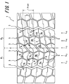
- FIG 1 is a development view of a portion of a tread surface of a pneumatic tire according to the present invention.
- FIG 1 is a development view of a portion of a tread surface of the pneumatic tire according to the present invention.
- FIG. 2 is a diagram illustrating a block arrangement in which side regions, before displacement thereof, are line symmetric with respect to a tire equator as an axis of symmetry.
- FIG 3 is a graph showing a relation between a displacement amount (ratio) of the side regions and a noise level.
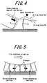
- FIG. 4 is a diagram illustrating block deformation of polygonal blocks adjacent to one another upon application of driving force.
- FIG 5 is a diagram illustrating the block deformation of the polygonal blocks that are adjacent to one another in a tire circumferential direction and closely arranged.
- FIG. 6(a) is a diagram illustrating the polygonal block in contact with the ground when pressed horizontally with respect to a road surface.
- FIG. 6(b) is a diagram illustrating the polygonal block in contact with the ground when pressed obliquely with respect to the road surface.
- FIG. 7 is a perspective view of the polygonal block indicating a direction of force when the polygonal block is pressed obliquely with respect to the road surface.
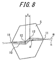
- FIG. 8 is an enlarged view of the polygonal block illustrated in FIG. 1 .
- FIG 1 illustrates a developed view of a portion of a tread surface 1 of the pneumatic tire according to the present invention (hereinafter, referred to as a "tire").
- a land portion defined by a pair of circumferential main grooves 2,2 extending in a zig-zag manner along a tire equator C on either side of the tire equator C is divided into at least five block rows L, here five block rows L 1 to L 5 , by at least four circumferential narrow grooves extending in the zig-zag manner along the tire equator C, here which are four circumferential narrow grooves 3, and also by multiple lateral grooves 4 communicating between the circumferential main groove 2 and a circumferential narrow groove 3 or between the circumferential narrow grooves 3, 3.
- the block 5 has a polygonal shape with at least five corners. In an illustrated example, the block 5 is a hexagonal block.
- a plurality of polygonal blocks 5 are closely and densely arranged between the circumferential main grooves 2, 2.
- the present invention it is important to provide, in a block arrangement having the polygonal blocks 5 described above arranged in a line-symmetric manner with the tire equator C as the axis of symmetry and closely and densely arranged, a phase difference of 0.2 to 0.4 times of a repetition pitch of a pattern of the block row L between the side regions facing each other across the tire equator C.
- the block arrangement having the polygonal blocks 5 arranged in the line-symmetric manner with the tire equator C as the axis of symmetry means a block arrangement in which, as illustrated in FIG 2 , polygonal blocks 5a, 5b disposed in a side region R 1 on the left-hand side of the tire equator C in the figure and polygonal blocks 5d, 5e disposed in a side region R 2 on the right-hand side of the tire equator C in the figure are line symmetric with respect to the tire equator C.
- the side region R 1 represents a region extending in a tire width direction from the tire equator C to a tire width direction outermost point of the block row L 1
- the side region R 2 represents a region extending in the tire width direction from the tire equator C to a tire width direction outermost point of the block row L 5 .
- the present invention is characterized in displacing one of the side regions R 1 and R 2 from the other in the tire circumferential direction by a displacement amount of 0.2 to 0.4 times of one pitch.
- the entire side region R 2 in FIG 2 illustrating the block arrangement before the displacement is displaced from the side region R 1 in the tire circumferential direction (in an upward direction in the figure), such that a vertex a of a polygonal block 5c in FIG 2 corresponds to a vertex A of the polygonal block 5c in FIG. 1 illustrating the block arrangement after the displacement.
- a distance t in the tire circumferential direction between the vertex a and the vertex A is 0.2 to 0.4 times of one pitch.
- the block row L is formed by repetition of a block pattern having the polygonal block 5 arranged in the tire circumferential direction.
- the "one pitch" refers to a length, in the tire circumferential direction, of a repetition unit of the block pattern in the block rows other than the block row located across the tire equator C.
- the "one pitch” refers to a length, in the tire circumferential direction, of the block row other than the block row L 3 located across the tire equator C, i.e., here, a length, in the tire circumferential direction, from an end P 1 of the polygonal block 5 in the block row L 5 to an end P 2 at a corresponding position of another polygonal block 5 adjacent to the above polygonal block 5.
- the displacement of the side region as a unit in the tire circumferential direction with respect to the tire equator C as a boundary allows maintaining, in each of the side regions, the shape of a plurality of polygonal blocks 5 and a geometric block arrangement having the polygonal blocks 5 closely and densely arranged and, simultaneously, providing a phase difference between a plurality of block rows L. That is, at the stage of FIG. 2 before displacement of the region in the tire circumferential direction, the polygonal blocks 5a, 5e are located at corresponding positions in the tire width direction and the polygonal blocks 5b, 5d are located at corresponding positions in the tire width direction. On the other hand, in FIG.
- the polygonal blocks 5a, 5b, 5d, and 5e are arranged such that none of block ends thereof becomes collinear in the tire width direction.
- those block ends are positioned in such a manner that all of the polygonal blocks 5a to 5e between the circumferential main grooves 2, 2 contact with the road surface at different timings. Therefore, according to a design of the present invention that provides the phase difference by displacement of the side region in the tire circumferential direction, various functions of the block arrangement having the polygonal blocks 5 closely and densely arranged may be maintained and, simultaneously, the polygonal blocks 5 in each of the block rows L may contact with the ground at different timings, thereby reducing a pattern noise.
- a horizontal axis represents the displacement amount (mm) in the tire circumferential direction with respect to a length (mm) of the one pitch in the tire circumferential direction (a pitch displacement ratio), and a vertical axis represents a value, as an index, obtained by counting chronological timings at which the kick-in end portions of the blocks contact with the ground surface and predicting data thereof by frequency resolution.
- tire rotation number ⁇ number of pitches As a result of a frequency characteristics analysis, it was found out that a primary component is present around 290 Hz (tire rotation number ⁇ number of pitches) and the secondary component is present around 580 Hz (tire rotation number ⁇ number of pitches ⁇ 2) and also that the secondary component reaches a peak. Therefore, it was aimed to suppress the secondary component.
- the reason for the secondary component to reach the peak is considered that, as described above, in one pitch the block includes the lug and the sipe and the noise increases at every 0.5 pitch, that is, the secondary component becomes large.
- the side regions are displaced from each other in the tire circumferential direction to have the phase difference of 0.24 to 0.32 times of the repetition pitch of the pattern of the block row L.
- the displacement between the side regions facing each other across the tire equator C in the tire circumferential direction may more significantly reduce the noise caused by the pattern noise.
- any one of the block rows L is preferably located across the tire equator C.
- the block row L 3 including the polygonal block 5c is located across the tire equator C.
- a heaviest load is applied to the equator C. Therefore, an arrangement allowing continual presence of the blocks on the tire equator C may secure rigidity of the tire.
- the polygonal blocks 5 constituting the block row L 3 located across the tire equator C preferably have shapes displaced and stretched in the tire circumferential direction.
- the side regions facing each other across the tire equator C are displaced from each other in the tire circumferential direction in such a manner that the polygonal blocks in the block row L 3 located across the tire equator C extend in the tire circumferential direction.
- the polygonal blocks other than those on the tire equator C i.e., the polygonal blocks constituting the block rows L 1 , L 2 , L 4 L 5 may be maintained in the shapes the same as those before the displacement in the tire circumferential direction. Accordingly, while the various functions of the polygonal blocks in the block arrangement before the displacement of the side regions in the tire circumferential direction are maintained, the noise may be advantageously reduced.
- the polygonal blocks 5 constituting the block rows L adjacent to one another in a tire width direction across the tire circumferential narrow groove 3 are displaced from each other in the tire circumferential direction, and also that a groove width d 2 of the circumferential narrow groove formed between the polygonal blocks 5 adjacent to one another in the tire width direction is smaller than a groove width d 1 of a lateral groove 4 formed between the polygonal blocks 5 adjacent to one another in the tire circumferential direction.
- the above design is adopted in such a manner that, as illustrated in FIG. 4 , reaction force of lift generated upon application of the driving force due to an increase in shear deformation of the polygonal block 5 that has finished kick-in is utilized so as to increase deformation of a next polygonal block 5 pressed against the road, thereby efficiently generating the driving force at the time of kick-in.
- reaction force of lift generated upon application of the driving force due to an increase in shear deformation of the polygonal block 5 that has finished kick-in is utilized so as to increase deformation of a next polygonal block 5 pressed against the road, thereby efficiently generating the driving force at the time of kick-in.
- the polygonal blocks 5 constituting the block rows L adjacent to one another in the tire width direction be displaced from one another in the tire circumferential direction, while the polygonal blocks 5 are closely and densely arranged with a short distance therebetween.
- the groove width d 2 of the circumferential narrow groove is set to be smaller than the groove width d 1 of the lateral groove 4.
- the groove width d 1 of the lateral groove 4 refers to a normal distance of a groove wall between the polygonal blocks 5 adjacent to one another in the tire circumferential direction
- the groove width d 2 of the circumferential narrow groove refers to a normal distance of the groove wall between the polygonal blocks 5 adjacent to one another in the tire width direction.
- the reduction in the increasing amount of the circumferential shear force between the time of kick-in and the time of kick-out may suppress excessive leaning of the polygonal blocks 5, thereby improving the wear resistance. Further, the suppression of the deformation of the polygonal block 5 allows reduction in rolling resistance and improvement in steering stability.
- the groove width d 2 of the circumferential narrow groove is preferably 0.5 to 3.0 mm.
- the bulging is suppressed and, as a result, the deformation of the polygonal blocks 5 is also suppressed.
- the groove width d 2 of the circumferential narrow groove is equal to or less than 3.0 mm
- the polygonal blocks 5 adjacent to one another in the tire width direction come into contact with one another at the time of ground contact.
- the deformation of the polygonal blocks 5 may be suppressed and further reduction in the rolling resistance as well as further improvement in the steering stability may be achieved.
- the reason to have the groove with d 2 at least 0.5 mm is that wet turning performance, i.e., water drainage performance becomes deteriorated when the groove is completely closed.
- a groove width d3 of the circumferential main groove 2 provided on the tread surface 1 is preferably wider than the groove width d 2 of the circumferential narrow groove and has an enough width to be able to prevent the groove from closing at the time of ground contact.
- a length of the polygonal block 5 in the tire width direction preferably increases from either tire circumferential end to a center thereof.
- the length of the polygonal block 5b in tire width direction preferably increases from tire circumferential ends 6, 6 of the polygonal blocks 5b to a center 7 of the polygonal block 5b.
- components R of the force Q are generated from a left-side wall and a right-side wall of the polygonal block 5b in directions opposite to each other and cancel out each other within the polygonal block 5b.
- a component P resists the force to deform the rubber in the center of the polygonal block 5b to deform from the kick-out end 8 toward a kick-in end 9. As a result, excessive deformation of the polygonal block 5b is suppressed and the sliding wear of the polygonal block 5b may be suppressed.
- the polygonal block 5 is preferably provided with a sipe 10commmicating, in the tire width direction, between the circumferential grooves adjacent to the polygonal block 5.
- the sipe is a groove that, when a tire has a prescribed internal pressure and a prescribed load applied thereto, closes at the time of ground contact and opens at the time of kick-in and also at the time of kick-out.
- further providing the kick-out end to the polygonal block 5 allows overall improvement in grip force of the polygonal block 5 and, as a result, torque from an engine may be efficiently converted into the driving force. Also, providing the sipe 10 ensures the water drainage performance.
- the sipe 10 described above preferably has a crank shape.
- the sipe 10 opens at the time of kick-in and at the time of kick-out, the polygonal block 5 deforms, possibly causing energy loss and deteriorating block rigidity.
- the sipe 10 may be suppressed from opening. Thereby, the effect of the sipe described above may be maintained and, simultaneously, the reduction in the rolling resistance and the improvement in the steering resistance may be achieved.
- providing the sipe 10 increases the number of grooves in the polygonal block 5, thereby causing a ground contact noise when the grooves contact with the ground. Accordingly, when the sipe 10 is formed in the crack shape as described above, the entire sipe 10 may contact with the ground at various timings unlike a sipe formed in a straight line in the tire width direction, leading to suppression of generation of the noise.
- the polygonal block 5 is preferably hexagonal.
- an acute angle ⁇ between a straight line m (a solid line) connecting sipe width midpoints 11, 11 of open ends of the sipe 10 and a line n (a broken line) indicating a center of the sipe is preferably 5 to 25 degrees.
- the acute angle ⁇ is smaller than 5 degrees, the effect of meshing of the divided portions of the polygonal block 5 is reduced.
- the acute angle ⁇ exceeds 25 degrees, an angle with respect to the tire width direction is so large that stiffness is locally reduced and the polygonal block 5 could be torn off.
- a tire width direction distance x between two tire width direction outermost inflection points 12, 12 of the sipe is preferably at most 1/2 of a maximum length of the polygonal block 5 in the tire width direction.
- the maximum length of the polygonal block 5 in the tire width direction refers to a distance between tire width direction outermost points of the polygonal block 5.
- a circumferential width of the polygonal block 5 is preferably longer than a lateral width thereof.
- a pitch length is longer. The longer the pitch length is, the number of pitches reduces. As a result, the pattern noise caused by the polygonal block 5 is reduced.
- the blocks similar to the polygonal block 5 are arranged outside of the circumferential main grooves 2, 2 with respect to the width direction, a design outside of the circumferential main grooves 2, 2 with respect to the width direction is not necessarily limited thereto.
- FIG. 1 illustrates five block rows L, six or more block rows L may be provided.
- pneumatic tires according to the present invention (present invention example tires 1 to 5), a conventional pneumatic tire (an exemplary conventional tire), and comparative example tires 1, 2 having different displacement amounts of the side regions were produced as test tires in size of 495/45R22.5 for a heavy duty vehicle. Then, performance of each of the tires was evaluated.
- the present invention example tire 1 is a pneumatic tire having the design of the tread surface corresponding to FIG. 1 in which the displacement amount between the side regions in the tire circumferential direction is 0.20 times of the repetition pitch of the pattern of the block L.
- the present invention example tires 2 to 5 and the comparative example tires 1, 2 have the displacement amounts different from that of the present invention example tire 1.
- the exemplary conventional tire is a pneumatic tire having sipes on the tread surface with a design corresponding to FIG. 9 .
- Each of the present invention example tires 1 to 5, the comparative example tires 1,2, and the exemplary conventional tire has specifications shown in Table 1.
- each of the test tires was mounted on a rim in size of 17.00 ⁇ 22.5, and thus a tire wheel was obtained, which was then mounted on a drive wheel of a tractor vehicle used for the test.
- air pressure of 800 kPa (relative pressure) and a tire load of 57 kN were applied to the test tire, and the tire wheel run for 50000 km on a highway.
- a wear amount of the center of the polygonal block was measured.
- a value of the wear resistance is expressed by an index with respect to a wear amount of the center of block land portion of the exemplary conventional tire set to 100 as reference. The smaller the value is, the better the wear resistance is.
- a skilled test driver carried out, in a test course, a running test including a lane change at a speed of 80 km/h, tire travelling limit at the speed of 80 km/h, and acceleration from 50 km/h. Thereby, the steering stability was evaluated. The evaluation is based on how the skilled test driver felt and rated on a scale of 1 to 10.
Landscapes
- Engineering & Computer Science (AREA)
- Mechanical Engineering (AREA)
- Tires In General (AREA)
Applications Claiming Priority (2)
| Application Number | Priority Date | Filing Date | Title |
|---|---|---|---|
| JP2012008460A JP2013147121A (ja) | 2012-01-18 | 2012-01-18 | 空気入りタイヤ |
| PCT/JP2013/000052 WO2013108594A1 (ja) | 2012-01-18 | 2013-01-10 | 空気入りタイヤ |
Publications (3)
| Publication Number | Publication Date |
|---|---|
| EP2805835A1 EP2805835A1 (en) | 2014-11-26 |
| EP2805835A4 EP2805835A4 (en) | 2015-08-19 |
| EP2805835B1 true EP2805835B1 (en) | 2016-06-29 |
Family
ID=48799028
Family Applications (1)
| Application Number | Title | Priority Date | Filing Date |
|---|---|---|---|
| EP13738284.2A Not-in-force EP2805835B1 (en) | 2012-01-18 | 2013-01-10 | Pneumatic tire |
Country Status (5)
| Country | Link |
|---|---|
| US (1) | US9481212B2 (en:Method) |
| EP (1) | EP2805835B1 (en:Method) |
| JP (1) | JP2013147121A (en:Method) |
| CN (1) | CN104053559A (en:Method) |
| WO (1) | WO2013108594A1 (en:Method) |
Families Citing this family (12)
| Publication number | Priority date | Publication date | Assignee | Title |
|---|---|---|---|---|
| JP6050802B2 (ja) * | 2014-11-18 | 2016-12-21 | 住友ゴム工業株式会社 | 重荷重用空気入りタイヤ |
| JP6514591B2 (ja) * | 2015-07-09 | 2019-05-15 | 住友ゴム工業株式会社 | 重荷重用空気入りタイヤ |
| JP6388013B2 (ja) * | 2016-10-26 | 2018-09-12 | 横浜ゴム株式会社 | 空気入りタイヤ |
| CN106827971B (zh) * | 2017-01-20 | 2019-04-16 | 安徽佳通乘用子午线轮胎有限公司 | 一种低噪音充气轮胎 |
| EP3360699B1 (en) * | 2017-02-08 | 2019-12-04 | Sumitomo Rubber Industries, Ltd. | Heavy duty tire and and method for manufacturing the same |
| US10682889B2 (en) | 2017-03-06 | 2020-06-16 | The Goodyear Tire & Rubber Company | Tire for autonomous vehicle |
| WO2018235345A1 (ja) * | 2017-06-22 | 2018-12-27 | 株式会社ブリヂストン | 重荷重用タイヤ |
| JP6933119B2 (ja) * | 2017-12-13 | 2021-09-08 | 住友ゴム工業株式会社 | タイヤ |
| JP7066515B2 (ja) * | 2018-05-17 | 2022-05-13 | Toyo Tire株式会社 | 空気入りタイヤ |
| IT201800007028A1 (it) * | 2018-07-09 | 2020-01-09 | Battistrada di pneumatici tbr di ruote motrici | |
| JP7143717B2 (ja) * | 2018-10-12 | 2022-09-29 | 住友ゴム工業株式会社 | タイヤ |
| JP7587115B2 (ja) * | 2020-09-30 | 2024-11-20 | 横浜ゴム株式会社 | タイヤ |
Family Cites Families (19)
| Publication number | Priority date | Publication date | Assignee | Title |
|---|---|---|---|---|
| GB520231A (en) * | 1938-09-16 | 1940-04-18 | Dunlop Rubber Co | Improvements in treads for pneumatic tyres |
| FR2452391A1 (fr) * | 1979-03-27 | 1980-10-24 | Kleber Colombes | Pneumatique pour vehicule |
| JPH0487806A (ja) * | 1990-07-31 | 1992-03-19 | Bridgestone Corp | 空気入りタイヤ用ブロック |
| ATE234207T1 (de) * | 1998-10-30 | 2003-03-15 | Pirelli | Luftreifen für motorfahrzeug, insbesondere für lkw und dergleichen |
| JP2001191739A (ja) * | 2000-01-13 | 2001-07-17 | Bridgestone Corp | 空気入りタイヤ |
| JP4209319B2 (ja) * | 2001-06-07 | 2009-01-14 | 株式会社ブリヂストン | オフザロードタイヤ |
| JP2007168572A (ja) * | 2005-12-21 | 2007-07-05 | Bridgestone Corp | 空気入りタイヤ |
| EP2151334B1 (en) | 2007-05-28 | 2014-09-10 | Bridgestone Corporation | Tire |
| JP2009190558A (ja) * | 2008-02-14 | 2009-08-27 | Bridgestone Corp | 空気入りタイヤ |
| US9308779B2 (en) * | 2008-06-25 | 2016-04-12 | Bridgestone Corporation | Tire |
| JP5295256B2 (ja) * | 2008-09-18 | 2013-09-18 | 株式会社ブリヂストン | タイヤの設計方法及びタイヤ |
| BRPI0921712A2 (pt) * | 2008-11-14 | 2016-01-05 | Bridgestone Corp | pneumático |
| EP2371583B1 (en) * | 2008-11-27 | 2014-02-12 | Bridgestone Corporation | Tire |
| JP5399849B2 (ja) * | 2009-10-08 | 2014-01-29 | 株式会社ブリヂストン | 空気入りタイヤ |
| JP5393404B2 (ja) * | 2009-11-05 | 2014-01-22 | 株式会社ブリヂストン | タイヤ |
| JP5421800B2 (ja) * | 2010-01-18 | 2014-02-19 | 株式会社ブリヂストン | 空気入りタイヤ |
| JP5506463B2 (ja) * | 2010-03-08 | 2014-05-28 | 株式会社ブリヂストン | 空気入りタイヤ |
| JP5609263B2 (ja) * | 2010-05-26 | 2014-10-22 | 横浜ゴム株式会社 | 空気入りタイヤ |
| JP5144720B2 (ja) * | 2010-06-17 | 2013-02-13 | 住友ゴム工業株式会社 | 空気入りタイヤ |
-
2012
- 2012-01-18 JP JP2012008460A patent/JP2013147121A/ja active Pending
-
2013
- 2013-01-10 WO PCT/JP2013/000052 patent/WO2013108594A1/ja not_active Ceased
- 2013-01-10 US US14/372,791 patent/US9481212B2/en not_active Expired - Fee Related
- 2013-01-10 EP EP13738284.2A patent/EP2805835B1/en not_active Not-in-force
- 2013-01-10 CN CN201380005652.8A patent/CN104053559A/zh active Pending
Also Published As
| Publication number | Publication date |
|---|---|
| EP2805835A1 (en) | 2014-11-26 |
| US9481212B2 (en) | 2016-11-01 |
| CN104053559A (zh) | 2014-09-17 |
| US20150151583A1 (en) | 2015-06-04 |
| JP2013147121A (ja) | 2013-08-01 |
| WO2013108594A1 (ja) | 2013-07-25 |
| EP2805835A4 (en) | 2015-08-19 |
Similar Documents
| Publication | Publication Date | Title |
|---|---|---|
| EP2805835B1 (en) | Pneumatic tire | |
| KR101857830B1 (ko) | 공기 타이어 | |
| JP5498466B2 (ja) | 重荷重用タイヤ | |
| KR101862879B1 (ko) | 중하중용 공기 타이어 | |
| JP6043270B2 (ja) | 空気入りタイヤ | |
| EP2465705B1 (en) | Pneumatic tire | |
| EP2311659B1 (en) | Pneumatic tire | |
| JP5261783B2 (ja) | 空気入りタイヤ | |
| US8887779B2 (en) | Pneumatic tire | |
| EP2497655A1 (en) | Tire | |
| US10471778B2 (en) | Pneumatic tire | |
| CN102189903B (zh) | 充气轮胎 | |
| JP4630308B2 (ja) | 重荷重用タイヤ | |
| EP2127907B1 (en) | Pneumatic tire | |
| US20090165911A1 (en) | Pneumatic tire | |
| JP5785602B2 (ja) | 重荷重用空気入りタイヤ | |
| EP2962872B1 (en) | Pneumatic tire | |
| JP2014156165A (ja) | 重荷重用空気入りタイヤ | |
| EP3015289B1 (en) | Pneumatic tire | |
| JP4977244B2 (ja) | 重荷重用タイヤ | |
| JP5446564B2 (ja) | 空気入りタイヤ | |
| JP5066980B2 (ja) | 空気入りタイヤ | |
| JP2006315433A (ja) | 空気入りタイヤ | |
| JP5193768B2 (ja) | 空気入りタイヤ | |
| JP5368786B2 (ja) | 空気入りタイヤ |
Legal Events
| Date | Code | Title | Description |
|---|---|---|---|
| PUAI | Public reference made under article 153(3) epc to a published international application that has entered the european phase |
Free format text: ORIGINAL CODE: 0009012 |
|
| 17P | Request for examination filed |
Effective date: 20140715 |
|
| AK | Designated contracting states |
Kind code of ref document: A1 Designated state(s): AL AT BE BG CH CY CZ DE DK EE ES FI FR GB GR HR HU IE IS IT LI LT LU LV MC MK MT NL NO PL PT RO RS SE SI SK SM TR |
|
| DAX | Request for extension of the european patent (deleted) | ||
| RA4 | Supplementary search report drawn up and despatched (corrected) |
Effective date: 20150721 |
|
| RIC1 | Information provided on ipc code assigned before grant |
Ipc: B60C 11/03 20060101ALI20150715BHEP Ipc: B60C 11/11 20060101AFI20150715BHEP Ipc: B60C 11/12 20060101ALI20150715BHEP |
|
| GRAP | Despatch of communication of intention to grant a patent |
Free format text: ORIGINAL CODE: EPIDOSNIGR1 |
|
| INTG | Intention to grant announced |
Effective date: 20160107 |
|
| GRAS | Grant fee paid |
Free format text: ORIGINAL CODE: EPIDOSNIGR3 |
|
| GRAA | (expected) grant |
Free format text: ORIGINAL CODE: 0009210 |
|
| AK | Designated contracting states |
Kind code of ref document: B1 Designated state(s): AL AT BE BG CH CY CZ DE DK EE ES FI FR GB GR HR HU IE IS IT LI LT LU LV MC MK MT NL NO PL PT RO RS SE SI SK SM TR |
|
| REG | Reference to a national code |
Ref country code: GB Ref legal event code: FG4D |
|
| REG | Reference to a national code |
Ref country code: CH Ref legal event code: EP |
|
| REG | Reference to a national code |
Ref country code: AT Ref legal event code: REF Ref document number: 808784 Country of ref document: AT Kind code of ref document: T Effective date: 20160715 |
|
| REG | Reference to a national code |
Ref country code: IE Ref legal event code: FG4D |
|
| REG | Reference to a national code |
Ref country code: DE Ref legal event code: R096 Ref document number: 602013008977 Country of ref document: DE |
|
| REG | Reference to a national code |
Ref country code: LT Ref legal event code: MG4D |
|
| PG25 | Lapsed in a contracting state [announced via postgrant information from national office to epo] |
Ref country code: NO Free format text: LAPSE BECAUSE OF FAILURE TO SUBMIT A TRANSLATION OF THE DESCRIPTION OR TO PAY THE FEE WITHIN THE PRESCRIBED TIME-LIMIT Effective date: 20160929 Ref country code: FI Free format text: LAPSE BECAUSE OF FAILURE TO SUBMIT A TRANSLATION OF THE DESCRIPTION OR TO PAY THE FEE WITHIN THE PRESCRIBED TIME-LIMIT Effective date: 20160629 Ref country code: LT Free format text: LAPSE BECAUSE OF FAILURE TO SUBMIT A TRANSLATION OF THE DESCRIPTION OR TO PAY THE FEE WITHIN THE PRESCRIBED TIME-LIMIT Effective date: 20160629 |
|
| REG | Reference to a national code |
Ref country code: NL Ref legal event code: MP Effective date: 20160629 |
|
| PG25 | Lapsed in a contracting state [announced via postgrant information from national office to epo] |
Ref country code: LV Free format text: LAPSE BECAUSE OF FAILURE TO SUBMIT A TRANSLATION OF THE DESCRIPTION OR TO PAY THE FEE WITHIN THE PRESCRIBED TIME-LIMIT Effective date: 20160629 Ref country code: NL Free format text: LAPSE BECAUSE OF FAILURE TO SUBMIT A TRANSLATION OF THE DESCRIPTION OR TO PAY THE FEE WITHIN THE PRESCRIBED TIME-LIMIT Effective date: 20160629 Ref country code: RS Free format text: LAPSE BECAUSE OF FAILURE TO SUBMIT A TRANSLATION OF THE DESCRIPTION OR TO PAY THE FEE WITHIN THE PRESCRIBED TIME-LIMIT Effective date: 20160629 Ref country code: SE Free format text: LAPSE BECAUSE OF FAILURE TO SUBMIT A TRANSLATION OF THE DESCRIPTION OR TO PAY THE FEE WITHIN THE PRESCRIBED TIME-LIMIT Effective date: 20160629 Ref country code: GR Free format text: LAPSE BECAUSE OF FAILURE TO SUBMIT A TRANSLATION OF THE DESCRIPTION OR TO PAY THE FEE WITHIN THE PRESCRIBED TIME-LIMIT Effective date: 20160930 Ref country code: HR Free format text: LAPSE BECAUSE OF FAILURE TO SUBMIT A TRANSLATION OF THE DESCRIPTION OR TO PAY THE FEE WITHIN THE PRESCRIBED TIME-LIMIT Effective date: 20160629 |
|
| REG | Reference to a national code |
Ref country code: AT Ref legal event code: MK05 Ref document number: 808784 Country of ref document: AT Kind code of ref document: T Effective date: 20160629 |
|
| REG | Reference to a national code |
Ref country code: FR Ref legal event code: PLFP Year of fee payment: 5 |
|
| PG25 | Lapsed in a contracting state [announced via postgrant information from national office to epo] |
Ref country code: SK Free format text: LAPSE BECAUSE OF FAILURE TO SUBMIT A TRANSLATION OF THE DESCRIPTION OR TO PAY THE FEE WITHIN THE PRESCRIBED TIME-LIMIT Effective date: 20160629 Ref country code: RO Free format text: LAPSE BECAUSE OF FAILURE TO SUBMIT A TRANSLATION OF THE DESCRIPTION OR TO PAY THE FEE WITHIN THE PRESCRIBED TIME-LIMIT Effective date: 20160629 Ref country code: CZ Free format text: LAPSE BECAUSE OF FAILURE TO SUBMIT A TRANSLATION OF THE DESCRIPTION OR TO PAY THE FEE WITHIN THE PRESCRIBED TIME-LIMIT Effective date: 20160629 Ref country code: EE Free format text: LAPSE BECAUSE OF FAILURE TO SUBMIT A TRANSLATION OF THE DESCRIPTION OR TO PAY THE FEE WITHIN THE PRESCRIBED TIME-LIMIT Effective date: 20160629 Ref country code: IS Free format text: LAPSE BECAUSE OF FAILURE TO SUBMIT A TRANSLATION OF THE DESCRIPTION OR TO PAY THE FEE WITHIN THE PRESCRIBED TIME-LIMIT Effective date: 20161029 |
|
| PG25 | Lapsed in a contracting state [announced via postgrant information from national office to epo] |
Ref country code: PL Free format text: LAPSE BECAUSE OF FAILURE TO SUBMIT A TRANSLATION OF THE DESCRIPTION OR TO PAY THE FEE WITHIN THE PRESCRIBED TIME-LIMIT Effective date: 20160629 Ref country code: AT Free format text: LAPSE BECAUSE OF FAILURE TO SUBMIT A TRANSLATION OF THE DESCRIPTION OR TO PAY THE FEE WITHIN THE PRESCRIBED TIME-LIMIT Effective date: 20160629 Ref country code: BE Free format text: LAPSE BECAUSE OF FAILURE TO SUBMIT A TRANSLATION OF THE DESCRIPTION OR TO PAY THE FEE WITHIN THE PRESCRIBED TIME-LIMIT Effective date: 20160629 Ref country code: SM Free format text: LAPSE BECAUSE OF FAILURE TO SUBMIT A TRANSLATION OF THE DESCRIPTION OR TO PAY THE FEE WITHIN THE PRESCRIBED TIME-LIMIT Effective date: 20160629 Ref country code: PT Free format text: LAPSE BECAUSE OF FAILURE TO SUBMIT A TRANSLATION OF THE DESCRIPTION OR TO PAY THE FEE WITHIN THE PRESCRIBED TIME-LIMIT Effective date: 20161031 Ref country code: ES Free format text: LAPSE BECAUSE OF FAILURE TO SUBMIT A TRANSLATION OF THE DESCRIPTION OR TO PAY THE FEE WITHIN THE PRESCRIBED TIME-LIMIT Effective date: 20160629 |
|
| REG | Reference to a national code |
Ref country code: DE Ref legal event code: R097 Ref document number: 602013008977 Country of ref document: DE |
|
| PG25 | Lapsed in a contracting state [announced via postgrant information from national office to epo] |
Ref country code: DK Free format text: LAPSE BECAUSE OF FAILURE TO SUBMIT A TRANSLATION OF THE DESCRIPTION OR TO PAY THE FEE WITHIN THE PRESCRIBED TIME-LIMIT Effective date: 20160629 |
|
| 26N | No opposition filed |
Effective date: 20170330 |
|
| PLBE | No opposition filed within time limit |
Free format text: ORIGINAL CODE: 0009261 |
|
| STAA | Information on the status of an ep patent application or granted ep patent |
Free format text: STATUS: NO OPPOSITION FILED WITHIN TIME LIMIT |
|
| PG25 | Lapsed in a contracting state [announced via postgrant information from national office to epo] |
Ref country code: SI Free format text: LAPSE BECAUSE OF FAILURE TO SUBMIT A TRANSLATION OF THE DESCRIPTION OR TO PAY THE FEE WITHIN THE PRESCRIBED TIME-LIMIT Effective date: 20160629 Ref country code: BG Free format text: LAPSE BECAUSE OF FAILURE TO SUBMIT A TRANSLATION OF THE DESCRIPTION OR TO PAY THE FEE WITHIN THE PRESCRIBED TIME-LIMIT Effective date: 20160929 |
|
| REG | Reference to a national code |
Ref country code: CH Ref legal event code: PL |
|
| GBPC | Gb: european patent ceased through non-payment of renewal fee |
Effective date: 20170110 |
|
| PG25 | Lapsed in a contracting state [announced via postgrant information from national office to epo] |
Ref country code: MC Free format text: LAPSE BECAUSE OF FAILURE TO SUBMIT A TRANSLATION OF THE DESCRIPTION OR TO PAY THE FEE WITHIN THE PRESCRIBED TIME-LIMIT Effective date: 20160629 |
|
| PG25 | Lapsed in a contracting state [announced via postgrant information from national office to epo] |
Ref country code: CH Free format text: LAPSE BECAUSE OF NON-PAYMENT OF DUE FEES Effective date: 20170131 Ref country code: LI Free format text: LAPSE BECAUSE OF NON-PAYMENT OF DUE FEES Effective date: 20170131 |
|
| REG | Reference to a national code |
Ref country code: IE Ref legal event code: MM4A |
|
| PG25 | Lapsed in a contracting state [announced via postgrant information from national office to epo] |
Ref country code: LU Free format text: LAPSE BECAUSE OF NON-PAYMENT OF DUE FEES Effective date: 20170110 Ref country code: GB Free format text: LAPSE BECAUSE OF NON-PAYMENT OF DUE FEES Effective date: 20170110 |
|
| REG | Reference to a national code |
Ref country code: FR Ref legal event code: PLFP Year of fee payment: 6 |
|
| PG25 | Lapsed in a contracting state [announced via postgrant information from national office to epo] |
Ref country code: IE Free format text: LAPSE BECAUSE OF NON-PAYMENT OF DUE FEES Effective date: 20170110 |
|
| PG25 | Lapsed in a contracting state [announced via postgrant information from national office to epo] |
Ref country code: MT Free format text: LAPSE BECAUSE OF NON-PAYMENT OF DUE FEES Effective date: 20170110 |
|
| PG25 | Lapsed in a contracting state [announced via postgrant information from national office to epo] |
Ref country code: AL Free format text: LAPSE BECAUSE OF FAILURE TO SUBMIT A TRANSLATION OF THE DESCRIPTION OR TO PAY THE FEE WITHIN THE PRESCRIBED TIME-LIMIT Effective date: 20160629 |
|
| PG25 | Lapsed in a contracting state [announced via postgrant information from national office to epo] |
Ref country code: HU Free format text: LAPSE BECAUSE OF FAILURE TO SUBMIT A TRANSLATION OF THE DESCRIPTION OR TO PAY THE FEE WITHIN THE PRESCRIBED TIME-LIMIT; INVALID AB INITIO Effective date: 20130110 |
|
| PG25 | Lapsed in a contracting state [announced via postgrant information from national office to epo] |
Ref country code: CY Free format text: LAPSE BECAUSE OF FAILURE TO SUBMIT A TRANSLATION OF THE DESCRIPTION OR TO PAY THE FEE WITHIN THE PRESCRIBED TIME-LIMIT Effective date: 20160629 |
|
| PG25 | Lapsed in a contracting state [announced via postgrant information from national office to epo] |
Ref country code: MK Free format text: LAPSE BECAUSE OF FAILURE TO SUBMIT A TRANSLATION OF THE DESCRIPTION OR TO PAY THE FEE WITHIN THE PRESCRIBED TIME-LIMIT Effective date: 20160629 |
|
| PG25 | Lapsed in a contracting state [announced via postgrant information from national office to epo] |
Ref country code: TR Free format text: LAPSE BECAUSE OF FAILURE TO SUBMIT A TRANSLATION OF THE DESCRIPTION OR TO PAY THE FEE WITHIN THE PRESCRIBED TIME-LIMIT Effective date: 20160629 |
|
| PGFP | Annual fee paid to national office [announced via postgrant information from national office to epo] |
Ref country code: DE Payment date: 20200121 Year of fee payment: 8 Ref country code: IT Payment date: 20200131 Year of fee payment: 8 |
|
| PGFP | Annual fee paid to national office [announced via postgrant information from national office to epo] |
Ref country code: FR Payment date: 20200121 Year of fee payment: 8 |
|
| REG | Reference to a national code |
Ref country code: DE Ref legal event code: R119 Ref document number: 602013008977 Country of ref document: DE |
|
| PG25 | Lapsed in a contracting state [announced via postgrant information from national office to epo] |
Ref country code: FR Free format text: LAPSE BECAUSE OF NON-PAYMENT OF DUE FEES Effective date: 20210131 |
|
| PG25 | Lapsed in a contracting state [announced via postgrant information from national office to epo] |
Ref country code: DE Free format text: LAPSE BECAUSE OF NON-PAYMENT OF DUE FEES Effective date: 20210803 |
|
| PG25 | Lapsed in a contracting state [announced via postgrant information from national office to epo] |
Ref country code: IT Free format text: LAPSE BECAUSE OF NON-PAYMENT OF DUE FEES Effective date: 20210110 |