EP2805633B9 - Schragen aus leitfähigem Kunststoff und Einrichtung sowie Verfahren zum automatischen Entleeren von mit stabförmigen Produkten gefüllten Schragen - Google Patents
Schragen aus leitfähigem Kunststoff und Einrichtung sowie Verfahren zum automatischen Entleeren von mit stabförmigen Produkten gefüllten Schragen Download PDFInfo
- Publication number
- EP2805633B9 EP2805633B9 EP14164574.7A EP14164574A EP2805633B9 EP 2805633 B9 EP2805633 B9 EP 2805633B9 EP 14164574 A EP14164574 A EP 14164574A EP 2805633 B9 EP2805633 B9 EP 2805633B9
- Authority
- EP
- European Patent Office
- Prior art keywords
- tray
- trays
- emptying
- rod
- shaped articles
- Prior art date
- Legal status (The legal status is an assumption and is not a legal conclusion. Google has not performed a legal analysis and makes no representation as to the accuracy of the status listed.)
- Active
Links
Images


Classifications
-
- A—HUMAN NECESSITIES
- A24—TOBACCO; CIGARS; CIGARETTES; SIMULATED SMOKING DEVICES; SMOKERS' REQUISITES
- A24C—MACHINES FOR MAKING CIGARS OR CIGARETTES
- A24C5/00—Making cigarettes; Making tipping materials for, or attaching filters or mouthpieces to, cigars or cigarettes
- A24C5/35—Adaptations of conveying apparatus for transporting cigarettes from making machine to packaging machine
- A24C5/352—Adaptations of conveying apparatus for transporting cigarettes from making machine to packaging machine using containers, i.e. boats
- A24C5/356—Emptying the boats into the hopper of the packaging machine
-
- A—HUMAN NECESSITIES
- A24—TOBACCO; CIGARS; CIGARETTES; SIMULATED SMOKING DEVICES; SMOKERS' REQUISITES
- A24C—MACHINES FOR MAKING CIGARS OR CIGARETTES
- A24C5/00—Making cigarettes; Making tipping materials for, or attaching filters or mouthpieces to, cigars or cigarettes
- A24C5/35—Adaptations of conveying apparatus for transporting cigarettes from making machine to packaging machine
- A24C5/352—Adaptations of conveying apparatus for transporting cigarettes from making machine to packaging machine using containers, i.e. boats
- A24C5/358—Boat constructions
Definitions
- the present invention relates to trays for receiving rod-shaped products of the tobacco processing industry, comprising a tray body formed by a rear wall, two at least substantially parallel and spaced apart side walls and a bottom wall, forming a receiving space for the products that is open at the front and at the top, wherein the tray can be designed as a shaft tray.
- the invention also relates to a tray emptying device for automatically emptying trays filled with rod-shaped products into a production or packaging machine in the tobacco processing industry, comprising a feed device for feeding trays filled with rod-shaped products, an emptying station with an emptying position for overhead emptying of the trays, a A transport device for transporting away the emptied trays and a transfer device for transporting the trays within the tray emptying device during an emptying cycle, and a method for automatically emptying trays filled with rod-shaped products, comprising the steps of feeding trays filled with products by means of a feed device, transporting the trays from the feed device into an emptying position of an emptying station by means of a transfer device, so that the trays are upside down in the emptying position , overhead emptying of the trays, transporting the empty trays by means of the transfer device from the emptying position to a transport device, and transporting away the empty trays by means of the transport device.
- the trays described are used in particular in the tobacco processing industry when processing rod-shaped products.
- Tobacco rods, cigarettes, filter rods and in particular filter rod segments or the like are kept in containers, the so-called trays, in particular for transport and storage.
- the containers can be designed as standard trays with a single receiving space for all products or as shaft trays in which the products are located in several shafts that are separate from one another.
- For further processing of the stored products these are delivered to downstream devices, such as packing machines or the like, or introduced into an existing mass flow.
- Such trays are now usually made of plastic such as polystyrene (PS) or acrylonitrile butadiene styrene (ABS), since this material is stable and at the same time light and inexpensive.
- PS polystyrene
- ABS acrylonitrile butadiene styrene
- Such trays are, for example, in DE-Gbm. 1,882,950.
- a downstream device in which trays are used is a tray emptying device, with the help of which rod-shaped articles that are stored in trays for various reasons are reintroduced into the production process.
- the tray emptying devices are combined with production machines to form a production arrangement for carrying out corresponding production processes, which include cigarette production, filter production and also the packaging of the same.
- Known tray emptying devices have transfer devices for manipulating or handling the trays, which are designed as a pivoting mechanism. With the known pivoting mechanism, all the trays, ie the full trays and the empty trays, are handled during the emptying cycle.
- An emptying cycle includes removing the full trays from the feed device, emptying the full trays overhead in the emptying station and delivering the empty trays to the removal device.
- tray emptying devices are, for example, in DE 10 2008 027 636 described.
- the WO2011/090395 two measures on the one hand blowing ionized compressed air into the bottom of the trays to neutralize the charge, on the other hand using an insert or an insert made of a conductive material inside the tray to essentially prevent the occurrence of electrostatic charges.
- a tray having the features of claim 1 .
- electrically conductive plastic as the tray material, any charging that occurs can be dissipated immediately. It is not necessary to apply an additional layer, insert or the like.
- the tray can be made structurally very simple.
- An electrically conductive plastic within the meaning of the invention is a plastic which--unlike plastics which are usually considered excellent insulators--has an electrical conductivity of at least 10 -10 S cm -1 .
- electrically conductive plastics are understood to mean the so-called intrinsically conductive polymers, which have conductivity per se.
- the tray is designed in one piece and is produced by injection molding. In this way, a very stable tray is obtained, which at the same time is inexpensive to produce.
- Existing molds for producing trays can also continue to be used, since only the material changes, while the tray mold remains identical.
- the tray according to the invention can also be a shaft tray, ie a tray in which the products lie in several shafts separated from one another by intermediate walls.
- the partitions are also made of electrically conductive plastic.
- the electrically conductive plastic is an intrinsically conductive polymer, in particular a doped intrinsically conductive polymer.
- the intrinsically conductive polymers are in particular cis-polyacetylene (cis-PA), trans-polyacetylene (trans-PA), poly(paraphenylene) (PPP), polythiophene, polypyrrole, poly(para-phenylene-vinylene) (PPV) and polyaniline (PANI).
- cis-PA cis-polyacetylene
- trans-PA trans-polyacetylene
- PPP poly(paraphenylene)
- PPP polythiophene
- polypyrrole poly(para-phenylene-vinylene)
- PANI polyaniline
- the conductive plastic tray according to the invention exhibits greatly reduced adhesion of the articles to its inner walls. This has an advantageous effect on the filling and the emptying operations, but this could possibly have an adverse effect on safe transport of the upright trays filled with rod-shaped articles, especially during acceleration and/or deceleration operations.
- the rear wall of the tray is inclined on its inside by at least 1 degree from the vertical relative to the vertical outside, with the wall thickness of the rear wall increasing from top to bottom toward the bottom wall.
- the bottom wall of the tray is inclined on its inside by at least 1 degree from the horizontal compared to the horizontal outside, with the wall thickness of the bottom wall decreasing from front to back towards the rear wall.
- the inner sides of the back wall and the bottom wall are inclined by approximately the same angular amount, such that the included angle is approximately 90 degrees.
- the trays are tilted for filling or emptying by means of a pivoting device in such a way that the inside of the rear wall of the tray is in the same, preferably vertical, plane as the upstream or downstream rear wall of the intermediate or buffer store of the tray filling device or the tray emptying device.
- a tray emptying device of the type mentioned at the outset in which at least one charge-dissipating element is provided on at least one device selected from the feed device, emptying station, removal device and transfer device, which is designed and set up to prevent contact between the tray and the grounded machine base frame.
- the trays are made of electrically conductive plastic, since this allows the charge produced by friction to be dissipated.
- the charge is discharged from the tray.
- Customary machines and devices in the tobacco processing industry have a machine base frame to which the individual components and parts are attached. This machine base frame is always grounded. It is therefore ideally suited to dissipate the resulting charge. To do this, it is necessary to establish a conductive connection between the charged trays and the machine base frame.
- this is provided by at least one charge-dissipating element, which is attached either to the feed device, to the emptying station, to the removal device or to the transfer device.
- the charge-dissipating element or the charge-dissipating elements can be designed in particular as contact surfaces made of metal. Silver, copper and iron, which are good electrical conductors, are particularly suitable as metals.
- its transfer device has a pivoting mechanism that performs a pivoting movement limited to 180°, with a pivoting cassette that can pivot about a stationary pivoting axis S, which is designed and set up for fixing, pivoting, and releasing the trays, with the pivoting axis containing the charge-dissipating element is.
- a particularly good discharge is guaranteed if the swivel mechanism is additionally provided with a copper mesh. Since the panning movement of the cassette is limited to 180°, problems caused by the braid twisting are eliminated.
- the feed device and/or removal device is/are designed as a conveyor belt, with the conveyor belt consisting of an electrically conductive plastic. In this way, the charging that occurs as a result of the friction between the trays and the conveyor belt is largely avoided.
- the object is also achieved by a method of the type mentioned at the outset, in which the trays of the present invention are used as trays and in which charge dissipation takes place in at least one of the method steps.
- the static charge in the trays is reduced to such an extent that stick-shaped products getting caught in the trays after the emptying process should essentially be ruled out.
- the method is particularly effective and at the same time simple, since no complex additional devices, for example for deionization, have to be provided.
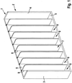
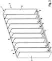
- the in the Figures 1 to 3 Trays shown by way of example are used in the tobacco processing industry in particular for transporting and storing rod-shaped products such as cigarettes, filter rods or the like. for use.
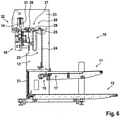
- the in the Figures 4 to 6 The emptying device shown by way of example is used for sequentially emptying containers filled with rod-shaped products into an emptying magazine or the like.
- the features and feature combinations described below can also be implemented in combinations other than those shown.
- the Figures 1 to 3 show a shaft tray 1, which has two side walls 3 and 4, a bottom wall 5 and a rear wall 6 to form a tray body 2.
- the side walls 3 , 4 are arranged spaced apart essentially in parallel (may have draft angles, which cannot be seen from the figures) and laterally delimit a receiving space 7 defined by the tray body 2 .
- the bottom wall 5 delimits the receiving space 7 at the bottom.
- the shaft trays 1 are usually designed to be open at the front and at the top. Of course, front walls and cover elements can also be provided.
- the tray body 2 can be made in one piece or in several pieces.
- the receiving space 7 itself can be subdivided.
- a plurality of shaft walls 8 are preferably connected to the tray body 2 in a detachable or fixed manner in order to divide the receiving space 7 into a plurality of shafts 9 .
- the shaft walls 8 can also be formed integrally with the tray body 2 .
- the shaft walls 8 run parallel and spaced apart from one another or from the side walls 3, 4.
- the tray 1 can also be designed as a standard tray without shaft walls 8 .
- the tray is made of electrically conductive plastic , which is what is known as an intrinsically conductive polymer se has a conductivity.
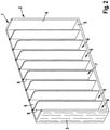
- the in the figures 2 and 3 Trays shown is an example not according to the invention and is made of a plastic with the addition of additives.
- Fibers of an inorganic substance are included as an additive.
- Such fibers can in particular be stainless steel fibers or carbon fibers.
- the conductivity in the fiber direction is significantly higher than perpendicular to it.
- the fibers are formed substantially parallel to the longitudinal extent of the tray side and partition walls 3, 8.
- the fibers run essentially parallel to the longitudinal extent of the tray base 5.
- the emptying device 10 shown comprises a feed device 11, a transport device 12, an emptying station 32 and a transfer device 13.
- the feed device 11 is used for feeding and storing products-filled (full) trays 14 made of electrically conductive material.
- the feed device 11 is arranged above the transport device 12 and, like the transport device 12, runs essentially horizontally.
- Substantially horizontally also expressly includes a slight inclination at an angle greater than 0° and less than 5° with respect to a horizontally spanned plane, such that the feed device 11 falls slightly in the direction of the transfer device 13, so that the containers 14 with respect to a vertical orientation inclined by the corresponding angle ⁇ on the feeder 11 are.
- an inclination of 3° from the vertical is selected.
- the transport device 12 serves to transport the emptied trays 16 away.
- the full trays 14 can be transported by means of the transfer device 13 from a pick-up position 17 into the area of an emptying magazine 18 and back into a delivery position 19 .
- the emptying magazine 18 can be part of the emptying station 32 or arranged as a separate part under the emptying position.
- In the area of the pick-up position 17 there is a stopper 15 which holds the tray in the pick-up position 17 until it is picked up by the transfer device.
- the feed device 11 continues to run below the tray 14, as a result of which electrostatic charges build up in the tray in conventional devices.
- the feed device 11 is designed as a conveyor belt, the conveyor belt consisting of a conductive plastic.
- the transfer device 13 comprises a cassette 21 which can be moved up and down vertically and is designed to be pivotable. The vertical and pivoting movements can be carried out directly or indirectly by the cassette 21. Furthermore, the cassette 21 is designed and set up to hold a tray 14, 16 during the entire emptying process. This means that the cassette has devices for holding and/or gripping the trays 14, 16, by means of which the trays 14, 16 are fixed within the cassette 21 in a defined position, which can also be inclined to the vertical. Pneumatic gripping elements are preferably provided. The trays 14, 16 themselves can be held, for example, by metallic spring elements or the like. Of course, all other conventional holding and/or gripping mechanisms made of conductive material can also be used.
- a pick-up element 22 is optionally assigned to the cassette 21 for receiving or picking up the full trays 14 from the feed device 11 .
- the pick-up element 22 is furthermore set up and designed to position the full tray 14 within the cassette 21 so that it can be fixed in the "middle product" position.
- the "middle product” position also known as “constant edge”, is advantageous for handling different product lengths in the course of a format change.
- the pick-up element 22 can furthermore also have a push-off element (not shown), by means of which the ejection of the emptied tray 16 from the cassette 21 is supported.
- the push-off element can also be provided as a separate device.
- the emptying device 10 preferably has a lift device 23 as part of the transfer device 13 in order to carry out the vertical movements from the pick-up position 17 to the transfer position 20 in the region of the pivoting device 27 and back to the delivery position 19 .
- the lift device 23 includes vertically running guide rails 24 or the like, on or in which a lift fork 25 or the like is guided, as well as a drive unit 26.
- the transfer device 13 also includes a pivoting device 27. The pivoting device 27 is between the transfer position 20 and the emptying position arranged and set up and designed to carry out an overhead pivoting movement of the full tray 14 holding the cassette 21 via the emptying magazine 18 and the then emptied tray 16 holding the cassette 21 back.
- the pivoting device 27 is arranged at the upper end of the guide rails 24 and forms a swivel head.
- the pivoting device 27 has a latching device 28 and a rotatable and stationary shaft 29 , with the latching device 28 being mounted on the shaft 29 .
- the shaft 29 itself is stationarily but rotatably mounted on a frame or the like.
- the shaft 29, together with the cassette 21, forms the charge-dissipating element, with the aid of which the charge present in the tray can be discharged via the base frame 33 of the emptying device 10.
- a copper mesh (not shown) can be provided in the area of the shaft 29, which supports the charge dissipation.
- the latching device 28 comprises a plurality of latching bolts (not shown), which can be actuated, for example, by means of pneumatic cylinders (also not shown) or the like.
- This means that the movably mounted locking bolts can be moved from a retracted waiting position, in which the cassette 21 can be coupled in or out during transfer from the lifting device 23 to the pivoting device 27 and back, to a locking position in which the cassette 21 is fixed to the pivoting device 27 is connected, and are movable back.
- the cassette 21 can be detached from the lifting device 23 and connected to the pivoting device 27 and vice versa.
- the locking of the cassette 21 on the pivoting device 27 and the corresponding unlocking can also take place in other conventional ways, provided that the conductive connection between the pivoting device 27, cassette 21 and tray 14 is established.
- the distance between the axis of rotation D of the shaft 29 and the cassette 21, which is rotatably or pivotably mounted on the shaft 29 by means of the locking device 28, is small.
- the latching device 28 is very short in terms of structural shape, so that the cassette 21 describes a very narrow envelope curve with a small radius during the pivoting movement.
- the cassette 21 is arranged in the immediate vicinity of the shaft 29 or directly on it.
- a drive 30 for executing the pivoting movement is assigned to the transfer device 13 and is arranged as an extension of the shaft 29 .
- the pick-up position 17 for the full trays 14 and the delivery position 19 for the emptied containers 16 can be at different positions.
- the pick-up position 17 preferably corresponds to the delivery position 19.
- both the pick-up position 17 and the delivery position 19 is also at the same level, namely at the height of the feed device 11.
- a lift device 31 is arranged in the area of the lower removal device 12.
- the lift device 31 for transporting the emptied containers 16 from the delivery position 19 to the removal device is designed separately from the lift device 23 for transporting the full trays 14 from the collection position 17 to the emptying position and back to the delivery position 19.
- At least one full tray 14, but preferably several full trays 14, are arranged or stored on the feed device 11.
- the trays 14 stand with one narrow side on the feeding device 11, which slopes slightly in the direction of the transfer device 13, so that the trays 14 are transported at an angle ⁇ to the vertical in the direction of the transfer device 13 into the pick-up position 17.
- the trays 14 can also be transported without being inclined.
- One full tray 14 is transported from the pick-up position 17 to the emptying position in the area of the emptying magazine 18 .
- the transport preferably takes place in that the full tray 14 is pulled into the cassette 21 by the pick-up element 22 and positioned there.
- either the tray 14 itself or the cassette 21 is pivoted through an angle to the vertical which is greater than the angle ⁇ . With this overall inclination by the angle ⁇ to the vertical, the cassette 21 with the tray 14 is moved vertically upwards into the area of the emptying magazine 18 by means of the lifting device 23 .
- the cassette 21 is detached from the lifting device 23 and connected to the pivoting device 27 .
- locking bolts of the locking device 28 are moved from a waiting position into the locking position, so that the cassette 21 is firmly connected to the shaft 29 of the pivoting device 27 .
- the shaft 29 is connected to the machine base frame 33 at the same time, so that a charge dissipation any electrostatic charge present in the tray 14 occurs.
- the pivoting device 27 performs a pivoting movement, so that the tray 14 is upside down above the emptying magazine 18.
- the closing element of the tray 14 is opened so that the products fall down out of the container 14 into the emptying magazine 18 .
- the cassette 21 with the emptied tray 16 pivots back.
- the cassette 21 with the emptied tray 16 is detached from the pivoting device 27 and reconnected to the lifting device 23 .
- the lift device 23 transports the emptied tray 16 down to the delivery position 19. During the entire emptying process from the collection position 17 to the area of the emptying magazine 18 and back to the delivery position 19, the tray 14, 16 in the cassette can be moved up and down and pivoted 21 held.
- tray 14, 16 is held permanently in the cassette 21 during the entire emptying process, ie during transport and emptying.
- electrostatic charge generated in the process on trays 14, 16 must be dissipated.
Landscapes
- Manufacturing Of Cigar And Cigarette Tobacco (AREA)
- Elimination Of Static Electricity (AREA)
- Filling Or Emptying Of Bunkers, Hoppers, And Tanks (AREA)
Priority Applications (1)
| Application Number | Priority Date | Filing Date | Title |
|---|---|---|---|
| PL14164574T PL2805633T5 (pl) | 2013-04-15 | 2014-04-14 | Korytka z przewodzącego tworzywa sztucznego i urządzenie oraz sposób automatycznego opróżniania napełnionych korytek z produktów w kształcie pręcika |
Applications Claiming Priority (1)
| Application Number | Priority Date | Filing Date | Title |
|---|---|---|---|
| DE102013103767.4A DE102013103767A1 (de) | 2013-04-15 | 2013-04-15 | Schragen aus leitfähigem Kunststoff und Einrichtung sowie Verfahren zum automatischen Entleeren von mit stabförmigen Produkten gefüllten Schragen |
Publications (5)
| Publication Number | Publication Date |
|---|---|
| EP2805633A1 EP2805633A1 (de) | 2014-11-26 |
| EP2805633B1 EP2805633B1 (de) | 2016-05-25 |
| EP2805633B8 EP2805633B8 (de) | 2016-07-13 |
| EP2805633B2 EP2805633B2 (de) | 2021-12-29 |
| EP2805633B9 true EP2805633B9 (de) | 2022-03-23 |
Family
ID=50478753
Family Applications (1)
| Application Number | Title | Priority Date | Filing Date |
|---|---|---|---|
| EP14164574.7A Active EP2805633B9 (de) | 2013-04-15 | 2014-04-14 | Schragen aus leitfähigem Kunststoff und Einrichtung sowie Verfahren zum automatischen Entleeren von mit stabförmigen Produkten gefüllten Schragen |
Country Status (4)
| Country | Link |
|---|---|
| EP (1) | EP2805633B9 (pl) |
| CN (1) | CN104097852B (pl) |
| DE (1) | DE102013103767A1 (pl) |
| PL (1) | PL2805633T5 (pl) |
Families Citing this family (6)
| Publication number | Priority date | Publication date | Assignee | Title |
|---|---|---|---|---|
| DE102013114071A1 (de) * | 2013-12-16 | 2015-06-18 | Hauni Maschinenbau Ag | Schragen sowie Schragenentleereinrichtung und Verfahren zum automatischen Entleeren von mit stabförmigen Artikeln der Tabak verarbeitenden Industrie gefüllten Schragen |
| DE102014116578A1 (de) * | 2014-10-24 | 2016-04-28 | Hauni Maschinenbau Ag | Anordnung und Verfahren zum Fördern eines aus stabförmigen Artikeln der Tabak verarbeitenden Industrie gebildeten Produktmassenstroms sowie Behälter zur Aufnahme und Abgabe von Portionen des Produktmassenstroms |
| DE102014016161A1 (de) * | 2014-11-04 | 2016-05-04 | Hauni Maschinenbau Ag | Schragen zur Aufnahme stabförmiger Artikel der Tabak verarbeitenden lndustrie sowie Transport- und/oder Speicheranordnung umfassend mindestens zwei Schragen zur Aufnahme stabförmiger Artikel der Tabak verarbeitenden Industrie |
| DE202015105643U1 (de) * | 2015-10-23 | 2015-11-23 | Hauni Maschinenbau Ag | Schragen aus leitfähigem Kunststoff |
| CN109196363A (zh) * | 2016-06-03 | 2019-01-11 | 豪夫迈·罗氏有限公司 | 实验室样品分配系统和实验室自动化系统 |
| CN111480880B (zh) * | 2020-04-30 | 2024-10-18 | 红云红河烟草(集团)有限责任公司 | 一种滤棒快速换盒装置 |
Family Cites Families (24)
| Publication number | Priority date | Publication date | Assignee | Title |
|---|---|---|---|---|
| GB694334A (en) | 1950-12-14 | 1953-07-15 | James Ernest Morris | Improvements in or relating to receptacles |
| DE1882950U (de) | 1962-10-04 | 1963-11-14 | Hauni Werke Koerber & Co Kg | Zigaretten-schragen. |
| US3406126A (en) | 1966-12-07 | 1968-10-15 | Avco Corp | Conductive synthetic resin composition containing carbon filaments |
| US4228194A (en) | 1979-05-14 | 1980-10-14 | Meeder Ernest P | Electrically conductive article and method of making the same |
| DE3001204A1 (de) | 1980-01-15 | 1981-07-30 | Bayer Ag, 5090 Leverkusen | Elektrisch leitfaehiges polycarbonat |
| NL193609C (nl) | 1981-12-30 | 2000-04-04 | Bekaert Sa Nv | Samengestelde streng voor verwerking als granulaat in kunststofproducten en werkwijze voor het vervaardigen van een kunststofmenggranulaat. |
| DE3543301A1 (de) | 1985-12-07 | 1987-06-11 | Roehm Gmbh | Elektrisch leitende feste kunststoffe |
| JP2552625B2 (ja) * | 1993-11-09 | 1996-11-13 | 淀川化成株式会社 | ガラス基板搬送用ボックス |
| EP0780594A1 (fr) | 1995-12-21 | 1997-06-25 | Elf Atochem S.A. | Courroies antistatiques |
| US6702091B2 (en) | 1998-09-15 | 2004-03-09 | Rolcon, Inc. | Conveyor roller assembly |
| US20020099119A1 (en) | 1999-05-27 | 2002-07-25 | Bradley D. Craig | Water-borne ceramer compositions and antistatic abrasion resistant ceramers made therefrom |
| IT1309297B1 (it) * | 1999-06-22 | 2002-01-22 | Gd Spa | Convogliatore a tasche. |
| DE10007479A1 (de) * | 2000-02-18 | 2001-08-23 | Hauni Maschinenbau Ag | Vorrichtung zum Fördern eines Faserstranges der tabakverarbeitenden Industrie |
| WO2005022603A2 (en) | 2003-09-02 | 2005-03-10 | Integral Technologies, Inc. | Low cost conductive containers manufactured from conductive loaded resin-based materials |
| DE102004055629A1 (de) * | 2004-11-12 | 2006-05-24 | Hauni Maschinenbau Ag | Vorrichtung und Verfahren zum aufeinanderfolgenden Entleeren von mit Artikeln gefüllten Behältern |
| DE102007013548A1 (de) * | 2007-03-17 | 2008-09-18 | Hauni Maschinenbau Ag | Modularer Schachtschragen |
| DE102007022868A1 (de) * | 2007-05-12 | 2008-11-13 | Hauni Maschinenbau Ag | Entleermagazin und Übergabeeinrichtung für einen Schragenentleerer, einen Schragenentleerer sowie ein Verfahren zum Entleeren von mit stabförmigen Produkten gefüllten Schragen und Weiterleiten der Produkte an nachgeordnete Vorrichtungen |
| PL212815B1 (pl) | 2008-05-29 | 2012-11-30 | Int Tobacco Machinery Poland | Urzadzenie do rozladowywania wypelnionych elementami pretopodobnymi kaset wielosegmentowych stosowanych w przemysle tytoniowym |
| DE102008027636A1 (de) * | 2008-06-07 | 2009-12-10 | Hauni Maschinenbau Ag | Vorrichtung und Verfahren zum aufeinander folgenden Entleeren von mit stabförmigen Produkten gefüllten Behältern |
| DE102009025568A1 (de) * | 2009-06-13 | 2010-12-16 | Hauni Maschinenbau Ag | Vorrichtung und Verfahren zum aufeinander folgenden Entleeren von mit stabförmigen Produkten gefüllten Behältern |
| PL221883B1 (pl) * | 2010-01-21 | 2016-06-30 | Int Tobacco Machinery Poland Spółka Z Ograniczoną Odpowiedzialnością | Sposób usuwania ładunków elektrostatycznych z kaset stosowanych do transportu elementów prętopodobnych, kaseta zabezpieczona przed negatywnym działaniem pola elektrostatycznego oraz urządzenie do rozładunku kaset wypełnionych elementami prętopodobnymi z jednoczesnym usuwaniem ładunków elektrostatycznych |
| CN201634598U (zh) * | 2010-03-25 | 2010-11-17 | 龙建萍 | 竹塑烟火药粒烘晒盘 |
| PL218620B1 (pl) | 2011-04-19 | 2015-01-30 | Int Tobacco Machinery Poland | Modułowa kaseta wielosegmentowa |
| DE102011053602A1 (de) * | 2011-09-14 | 2013-03-14 | Hauni Maschinenbau Ag | Schragen-Handhabungshilfe für einen Schragen zum Transportieren und/oder Bevorraten von stabförmigen Artikeln der Tabak verarbeitenden Industrie, Schragen mit einer solchen Schragen-Handhabungshilfe, Schragen-Entleermagazin zum Entleeren solcher Schragen sowie Schragenentleerer mit einem solchen Schragen-Entleermagazin |
-
2013
- 2013-04-15 DE DE102013103767.4A patent/DE102013103767A1/de not_active Ceased
-
2014
- 2014-04-14 CN CN201410147361.9A patent/CN104097852B/zh active Active
- 2014-04-14 PL PL14164574T patent/PL2805633T5/pl unknown
- 2014-04-14 EP EP14164574.7A patent/EP2805633B9/de active Active
Also Published As
| Publication number | Publication date |
|---|---|
| EP2805633A1 (de) | 2014-11-26 |
| DE102013103767A1 (de) | 2014-10-16 |
| EP2805633B1 (de) | 2016-05-25 |
| CN104097852B (zh) | 2020-09-01 |
| PL2805633T3 (pl) | 2016-11-30 |
| CN104097852A (zh) | 2014-10-15 |
| EP2805633B8 (de) | 2016-07-13 |
| EP2805633B2 (de) | 2021-12-29 |
| PL2805633T5 (pl) | 2022-05-02 |
Similar Documents
| Publication | Publication Date | Title |
|---|---|---|
| EP2805633B9 (de) | Schragen aus leitfähigem Kunststoff und Einrichtung sowie Verfahren zum automatischen Entleeren von mit stabförmigen Produkten gefüllten Schragen | |
| EP1955604B1 (de) | Vorrichtung und Verfahren zum Befüllen von Behältern mit stabförmigen Produkten | |
| DE102007005749A1 (de) | Entleermagazin und Verfahren zum Entleeren von mit stabförmigen Produkten gefüllten Schragen, insbesondere Schachtschragen | |
| DE2817094A1 (de) | Vorrichtung zum zusammenpressen und verpacken von gegenstaenden | |
| WO2018083292A9 (de) | Übergabestation, anordnung und verfahren zum übergeben von mit produkten der tabak verarbeitenden industrie gefüllten und/oder leeren und aus mindestens einem behälter gebildeten behälterblöcken aus einem lagersystem | |
| EP2130445B9 (de) | Vorrichtung und Verfahren zum aufeinander folgenden Entleeren von mit stabförmigen Produkten gefüllten Behältern | |
| WO2012139811A1 (de) | Vorrichtung zur kontrolle von pharmazeutischen produkten, insbesondere von hartgelatinekapseln | |
| DE602004001132T2 (de) | Ausrichtungsvorrichtung für flaschenvorformen zur hindurchführung durch eine blasmaschine | |
| EP3362251B1 (de) | Verfahren und vorrichtung zur bereitstellung eines vorrates an vorformlingen | |
| EP2100834B1 (de) | Handhabungsvorrichtung zum Transportieren von mit Artikeln gefüllten und/oder zu befüllenden Behältern | |
| DE102014206534A1 (de) | Fülleinrichtung zum Befüllen eines Behältnisses | |
| EP1303451A1 (de) | Vorrichtung zum einstapeln von flachen gegenständen in einseitig offene behälter | |
| EP3364786B1 (de) | Schragen aus leitfähigem kunststoff | |
| DE102021117317B4 (de) | Vorrichtung und Verfahren zur Eingabe von flachen Gegenständen in einen Transportbehälter | |
| DE102013208407A1 (de) | Vorrichtung und Verfahren zum Ändern des Füllstands von mit stabförmigen Artikeln befüllbaren oder gefüllten Transportbehältern | |
| EP2596708A9 (de) | Handhabungsanordnung für Transportbehälter für stabförmige Artikel der Tabak verarbeitenden Industrie, Umlaufkassette sowie Verfahren zum Verändern des Füllstandes von Transportbehältern | |
| EP2759216A9 (de) | Schragenentleereinrichtung und Verfahren zum automatischen Entleeren von mit stabförmigen Artikeln gefüllten Schragen in eine Produktionsmaschine der Tabak verarbeitenden Industrie sowie eine Produktionsanordnung mit einer Produktionsmaschine und mindestens zwei Schragenentleereinrichtungen | |
| DE102013114071A1 (de) | Schragen sowie Schragenentleereinrichtung und Verfahren zum automatischen Entleeren von mit stabförmigen Artikeln der Tabak verarbeitenden Industrie gefüllten Schragen | |
| DE102012002019A1 (de) | Verfahren und Vorrichtung zum egalisierten Verpacken von Beuteln in einem Sammelbehälter | |
| DE1957546U (de) | Uebernahme- und abgabeeinrichtung fuer geblasene hohlkoerper an kunststoff - blasmaschinen. | |
| EP4385909A1 (de) | Verfahren und übergabeeinrichtung zur übergabe von produkten von einer ersten fördereinrichtung zu einer zweiten fördereinrichtung | |
| WO2007090517A1 (de) | Vorrichtung und verfahren zum vereinzeln von produkten | |
| EP3056098A2 (de) | Verteilervorrichtung und verfahren zum beschicken einer strangmaschine der tabak verarbeitenden industrie mit einem aus fasermaterial bestehenden produktstrom | |
| DE1137665B (de) | Zigarettensammelvorrichtung | |
| DE202012100132U1 (de) | Vorrichtung zur Handhabung von Münzen mit einer Fallschutzeinheit |
Legal Events
| Date | Code | Title | Description |
|---|---|---|---|
| PUAI | Public reference made under article 153(3) epc to a published international application that has entered the european phase |
Free format text: ORIGINAL CODE: 0009012 |
|
| 17P | Request for examination filed |
Effective date: 20140414 |
|
| AK | Designated contracting states |
Kind code of ref document: A1 Designated state(s): AL AT BE BG CH CY CZ DE DK EE ES FI FR GB GR HR HU IE IS IT LI LT LU LV MC MK MT NL NO PL PT RO RS SE SI SK SM TR |
|
| AX | Request for extension of the european patent |
Extension state: BA ME |
|
| R17P | Request for examination filed (corrected) |
Effective date: 20150513 |
|
| RBV | Designated contracting states (corrected) |
Designated state(s): AL AT BE BG CH CY CZ DE DK EE ES FI FR GB GR HR HU IE IS IT LI LT LU LV MC MK MT NL NO PL PT RO RS SE SI SK SM TR |
|
| GRAP | Despatch of communication of intention to grant a patent |
Free format text: ORIGINAL CODE: EPIDOSNIGR1 |
|
| INTG | Intention to grant announced |
Effective date: 20151125 |
|
| RAP1 | Party data changed (applicant data changed or rights of an application transferred) |
Owner name: HAUNI MASCHINENBAU AG |
|
| GRAS | Grant fee paid |
Free format text: ORIGINAL CODE: EPIDOSNIGR3 |
|
| GRAA | (expected) grant |
Free format text: ORIGINAL CODE: 0009210 |
|
| GRAT | Correction requested after decision to grant or after decision to maintain patent in amended form |
Free format text: ORIGINAL CODE: EPIDOSNCDEC |
|
| AK | Designated contracting states |
Kind code of ref document: B1 Designated state(s): AL AT BE BG CH CY CZ DE DK EE ES FI FR GB GR HR HU IE IS IT LI LT LU LV MC MK MT NL NO PL PT RO RS SE SI SK SM TR |
|
| REG | Reference to a national code |
Ref country code: GB Ref legal event code: FG4D Free format text: NOT ENGLISH |
|
| REG | Reference to a national code |
Ref country code: CH Ref legal event code: EP |
|
| REG | Reference to a national code |
Ref country code: IE Ref legal event code: FG4D Free format text: LANGUAGE OF EP DOCUMENT: GERMAN Ref country code: AT Ref legal event code: REF Ref document number: 801480 Country of ref document: AT Kind code of ref document: T Effective date: 20160615 |
|
| REG | Reference to a national code |
Ref country code: DE Ref legal event code: R096 Ref document number: 502014000828 Country of ref document: DE |
|
| REG | Reference to a national code |
Ref country code: DE Ref legal event code: R081 Ref document number: 502014000828 Country of ref document: DE Owner name: HAUNI MASCHINENBAU GMBH, DE Free format text: FORMER OWNER: HAUNI MASCHINENBAU AG, 21033 HAMBURG, DE |
|
| REG | Reference to a national code |
Ref country code: NL Ref legal event code: FP |
|
| REG | Reference to a national code |
Ref country code: LT Ref legal event code: MG4D |
|
| REG | Reference to a national code |
Ref country code: NL Ref legal event code: PD Owner name: HAUNI MASCHINENBAU GMBH; DE Free format text: DETAILS ASSIGNMENT: VERANDERING VAN EIGENAAR(S), VERANDERING VAN DE JURIDISCHE ENTITEIT; FORMER OWNER NAME: HAUNI MASCHINENBAU AG Effective date: 20160928 |
|
| PG25 | Lapsed in a contracting state [announced via postgrant information from national office to epo] |
Ref country code: NO Free format text: LAPSE BECAUSE OF FAILURE TO SUBMIT A TRANSLATION OF THE DESCRIPTION OR TO PAY THE FEE WITHIN THE PRESCRIBED TIME-LIMIT Effective date: 20160825 Ref country code: FI Free format text: LAPSE BECAUSE OF FAILURE TO SUBMIT A TRANSLATION OF THE DESCRIPTION OR TO PAY THE FEE WITHIN THE PRESCRIBED TIME-LIMIT Effective date: 20160525 Ref country code: LT Free format text: LAPSE BECAUSE OF FAILURE TO SUBMIT A TRANSLATION OF THE DESCRIPTION OR TO PAY THE FEE WITHIN THE PRESCRIBED TIME-LIMIT Effective date: 20160525 |
|
| RAP2 | Party data changed (patent owner data changed or rights of a patent transferred) |
Owner name: HAUNI MASCHINENBAU GMBH |
|
| PG25 | Lapsed in a contracting state [announced via postgrant information from national office to epo] |
Ref country code: RS Free format text: LAPSE BECAUSE OF FAILURE TO SUBMIT A TRANSLATION OF THE DESCRIPTION OR TO PAY THE FEE WITHIN THE PRESCRIBED TIME-LIMIT Effective date: 20160525 Ref country code: LV Free format text: LAPSE BECAUSE OF FAILURE TO SUBMIT A TRANSLATION OF THE DESCRIPTION OR TO PAY THE FEE WITHIN THE PRESCRIBED TIME-LIMIT Effective date: 20160525 Ref country code: HR Free format text: LAPSE BECAUSE OF FAILURE TO SUBMIT A TRANSLATION OF THE DESCRIPTION OR TO PAY THE FEE WITHIN THE PRESCRIBED TIME-LIMIT Effective date: 20160525 Ref country code: ES Free format text: LAPSE BECAUSE OF FAILURE TO SUBMIT A TRANSLATION OF THE DESCRIPTION OR TO PAY THE FEE WITHIN THE PRESCRIBED TIME-LIMIT Effective date: 20160525 Ref country code: PT Free format text: LAPSE BECAUSE OF FAILURE TO SUBMIT A TRANSLATION OF THE DESCRIPTION OR TO PAY THE FEE WITHIN THE PRESCRIBED TIME-LIMIT Effective date: 20160926 Ref country code: SE Free format text: LAPSE BECAUSE OF FAILURE TO SUBMIT A TRANSLATION OF THE DESCRIPTION OR TO PAY THE FEE WITHIN THE PRESCRIBED TIME-LIMIT Effective date: 20160525 Ref country code: GR Free format text: LAPSE BECAUSE OF FAILURE TO SUBMIT A TRANSLATION OF THE DESCRIPTION OR TO PAY THE FEE WITHIN THE PRESCRIBED TIME-LIMIT Effective date: 20160826 |
|
| PG25 | Lapsed in a contracting state [announced via postgrant information from national office to epo] |
Ref country code: EE Free format text: LAPSE BECAUSE OF FAILURE TO SUBMIT A TRANSLATION OF THE DESCRIPTION OR TO PAY THE FEE WITHIN THE PRESCRIBED TIME-LIMIT Effective date: 20160525 Ref country code: SK Free format text: LAPSE BECAUSE OF FAILURE TO SUBMIT A TRANSLATION OF THE DESCRIPTION OR TO PAY THE FEE WITHIN THE PRESCRIBED TIME-LIMIT Effective date: 20160525 Ref country code: RO Free format text: LAPSE BECAUSE OF FAILURE TO SUBMIT A TRANSLATION OF THE DESCRIPTION OR TO PAY THE FEE WITHIN THE PRESCRIBED TIME-LIMIT Effective date: 20160525 Ref country code: CZ Free format text: LAPSE BECAUSE OF FAILURE TO SUBMIT A TRANSLATION OF THE DESCRIPTION OR TO PAY THE FEE WITHIN THE PRESCRIBED TIME-LIMIT Effective date: 20160525 Ref country code: DK Free format text: LAPSE BECAUSE OF FAILURE TO SUBMIT A TRANSLATION OF THE DESCRIPTION OR TO PAY THE FEE WITHIN THE PRESCRIBED TIME-LIMIT Effective date: 20160525 |
|
| REG | Reference to a national code |
Ref country code: DE Ref legal event code: R026 Ref document number: 502014000828 Country of ref document: DE |
|
| PLBI | Opposition filed |
Free format text: ORIGINAL CODE: 0009260 |
|
| PG25 | Lapsed in a contracting state [announced via postgrant information from national office to epo] |
Ref country code: SM Free format text: LAPSE BECAUSE OF FAILURE TO SUBMIT A TRANSLATION OF THE DESCRIPTION OR TO PAY THE FEE WITHIN THE PRESCRIBED TIME-LIMIT Effective date: 20160525 |
|
| PLBI | Opposition filed |
Free format text: ORIGINAL CODE: 0009260 |
|
| 26 | Opposition filed |
Opponent name: INTERNATIONAL TOBACCO MACHINERY POLAND SP. Z O.O. Effective date: 20170220 |
|
| PLAX | Notice of opposition and request to file observation + time limit sent |
Free format text: ORIGINAL CODE: EPIDOSNOBS2 |
|
| 26 | Opposition filed |
Opponent name: G.D S.P.A. Effective date: 20170227 |
|
| PG25 | Lapsed in a contracting state [announced via postgrant information from national office to epo] |
Ref country code: SI Free format text: LAPSE BECAUSE OF FAILURE TO SUBMIT A TRANSLATION OF THE DESCRIPTION OR TO PAY THE FEE WITHIN THE PRESCRIBED TIME-LIMIT Effective date: 20160525 |
|
| PLBB | Reply of patent proprietor to notice(s) of opposition received |
Free format text: ORIGINAL CODE: EPIDOSNOBS3 |
|
| REG | Reference to a national code |
Ref country code: CH Ref legal event code: PL |
|
| REG | Reference to a national code |
Ref country code: IE Ref legal event code: MM4A |
|
| REG | Reference to a national code |
Ref country code: FR Ref legal event code: ST Effective date: 20171229 |
|
| PG25 | Lapsed in a contracting state [announced via postgrant information from national office to epo] |
Ref country code: FR Free format text: LAPSE BECAUSE OF NON-PAYMENT OF DUE FEES Effective date: 20170502 Ref country code: MC Free format text: LAPSE BECAUSE OF FAILURE TO SUBMIT A TRANSLATION OF THE DESCRIPTION OR TO PAY THE FEE WITHIN THE PRESCRIBED TIME-LIMIT Effective date: 20160525 |
|
| PG25 | Lapsed in a contracting state [announced via postgrant information from national office to epo] |
Ref country code: LI Free format text: LAPSE BECAUSE OF NON-PAYMENT OF DUE FEES Effective date: 20170430 Ref country code: CH Free format text: LAPSE BECAUSE OF NON-PAYMENT OF DUE FEES Effective date: 20170430 Ref country code: LU Free format text: LAPSE BECAUSE OF NON-PAYMENT OF DUE FEES Effective date: 20170414 |
|
| REG | Reference to a national code |
Ref country code: BE Ref legal event code: MM Effective date: 20170430 |
|
| PG25 | Lapsed in a contracting state [announced via postgrant information from national office to epo] |
Ref country code: IE Free format text: LAPSE BECAUSE OF NON-PAYMENT OF DUE FEES Effective date: 20170414 |
|
| PG25 | Lapsed in a contracting state [announced via postgrant information from national office to epo] |
Ref country code: BE Free format text: LAPSE BECAUSE OF NON-PAYMENT OF DUE FEES Effective date: 20170430 |
|
| PG25 | Lapsed in a contracting state [announced via postgrant information from national office to epo] |
Ref country code: MT Free format text: LAPSE BECAUSE OF FAILURE TO SUBMIT A TRANSLATION OF THE DESCRIPTION OR TO PAY THE FEE WITHIN THE PRESCRIBED TIME-LIMIT Effective date: 20160525 |
|
| PG25 | Lapsed in a contracting state [announced via postgrant information from national office to epo] |
Ref country code: AL Free format text: LAPSE BECAUSE OF FAILURE TO SUBMIT A TRANSLATION OF THE DESCRIPTION OR TO PAY THE FEE WITHIN THE PRESCRIBED TIME-LIMIT Effective date: 20160525 |
|
| GBPC | Gb: european patent ceased through non-payment of renewal fee |
Effective date: 20180414 |
|
| APBM | Appeal reference recorded |
Free format text: ORIGINAL CODE: EPIDOSNREFNO |
|
| APBP | Date of receipt of notice of appeal recorded |
Free format text: ORIGINAL CODE: EPIDOSNNOA2O |
|
| APAH | Appeal reference modified |
Free format text: ORIGINAL CODE: EPIDOSCREFNO |
|
| APAJ | Date of receipt of notice of appeal modified |
Free format text: ORIGINAL CODE: EPIDOSCNOA2O |
|
| APBM | Appeal reference recorded |
Free format text: ORIGINAL CODE: EPIDOSNREFNO |
|
| APBP | Date of receipt of notice of appeal recorded |
Free format text: ORIGINAL CODE: EPIDOSNNOA2O |
|
| PG25 | Lapsed in a contracting state [announced via postgrant information from national office to epo] |
Ref country code: GB Free format text: LAPSE BECAUSE OF NON-PAYMENT OF DUE FEES Effective date: 20180414 |
|
| APBQ | Date of receipt of statement of grounds of appeal recorded |
Free format text: ORIGINAL CODE: EPIDOSNNOA3O |
|
| APBQ | Date of receipt of statement of grounds of appeal recorded |
Free format text: ORIGINAL CODE: EPIDOSNNOA3O |
|
| PG25 | Lapsed in a contracting state [announced via postgrant information from national office to epo] |
Ref country code: HU Free format text: LAPSE BECAUSE OF FAILURE TO SUBMIT A TRANSLATION OF THE DESCRIPTION OR TO PAY THE FEE WITHIN THE PRESCRIBED TIME-LIMIT; INVALID AB INITIO Effective date: 20140414 |
|
| PG25 | Lapsed in a contracting state [announced via postgrant information from national office to epo] |
Ref country code: BG Free format text: LAPSE BECAUSE OF FAILURE TO SUBMIT A TRANSLATION OF THE DESCRIPTION OR TO PAY THE FEE WITHIN THE PRESCRIBED TIME-LIMIT Effective date: 20160525 |
|
| APAH | Appeal reference modified |
Free format text: ORIGINAL CODE: EPIDOSCREFNO |
|
| PG25 | Lapsed in a contracting state [announced via postgrant information from national office to epo] |
Ref country code: CY Free format text: LAPSE BECAUSE OF FAILURE TO SUBMIT A TRANSLATION OF THE DESCRIPTION OR TO PAY THE FEE WITHIN THE PRESCRIBED TIME-LIMIT Effective date: 20160525 |
|
| PG25 | Lapsed in a contracting state [announced via postgrant information from national office to epo] |
Ref country code: MK Free format text: LAPSE BECAUSE OF FAILURE TO SUBMIT A TRANSLATION OF THE DESCRIPTION OR TO PAY THE FEE WITHIN THE PRESCRIBED TIME-LIMIT Effective date: 20160525 |
|
| PG25 | Lapsed in a contracting state [announced via postgrant information from national office to epo] |
Ref country code: TR Free format text: LAPSE BECAUSE OF FAILURE TO SUBMIT A TRANSLATION OF THE DESCRIPTION OR TO PAY THE FEE WITHIN THE PRESCRIBED TIME-LIMIT Effective date: 20160525 |
|
| PG25 | Lapsed in a contracting state [announced via postgrant information from national office to epo] |
Ref country code: IS Free format text: LAPSE BECAUSE OF FAILURE TO SUBMIT A TRANSLATION OF THE DESCRIPTION OR TO PAY THE FEE WITHIN THE PRESCRIBED TIME-LIMIT Effective date: 20160925 |
|
| REG | Reference to a national code |
Ref country code: AT Ref legal event code: MM01 Ref document number: 801480 Country of ref document: AT Kind code of ref document: T Effective date: 20190414 |
|
| PG25 | Lapsed in a contracting state [announced via postgrant information from national office to epo] |
Ref country code: AT Free format text: LAPSE BECAUSE OF NON-PAYMENT OF DUE FEES Effective date: 20190414 |
|
| APBU | Appeal procedure closed |
Free format text: ORIGINAL CODE: EPIDOSNNOA9O |
|
| PUAH | Patent maintained in amended form |
Free format text: ORIGINAL CODE: 0009272 |
|
| STAA | Information on the status of an ep patent application or granted ep patent |
Free format text: STATUS: PATENT MAINTAINED AS AMENDED |
|
| 27A | Patent maintained in amended form |
Effective date: 20211229 |
|
| AK | Designated contracting states |
Kind code of ref document: B2 Designated state(s): AL AT BE BG CH CY CZ DE DK EE ES FI FR GB GR HR HU IE IS IT LI LT LU LV MC MK MT NL NO PL PT RO RS SE SI SK SM TR |
|
| REG | Reference to a national code |
Ref country code: DE Ref legal event code: R102 Ref document number: 502014000828 Country of ref document: DE |
|
| REG | Reference to a national code |
Ref country code: NL Ref legal event code: FP |
|
| REG | Reference to a national code |
Ref country code: DE Ref legal event code: R081 Ref document number: 502014000828 Country of ref document: DE Owner name: KOERBER TECHNOLOGIES GMBH, DE Free format text: FORMER OWNER: HAUNI MASCHINENBAU GMBH, 21033 HAMBURG, DE |
|
| REG | Reference to a national code |
Ref country code: NL Ref legal event code: HC Owner name: KOERBER TECHNOLOGIES GMBH; DE Free format text: DETAILS ASSIGNMENT: CHANGE OF OWNER(S), CHANGE OF OWNER(S) NAME; FORMER OWNER NAME: HAUNI MASCHINENBAU GMBH Effective date: 20221020 |
|
| P01 | Opt-out of the competence of the unified patent court (upc) registered |
Effective date: 20230621 |
|
| PGFP | Annual fee paid to national office [announced via postgrant information from national office to epo] |
Ref country code: NL Payment date: 20250426 Year of fee payment: 12 |
|
| PGFP | Annual fee paid to national office [announced via postgrant information from national office to epo] |
Ref country code: DE Payment date: 20250430 Year of fee payment: 12 |
|
| PGFP | Annual fee paid to national office [announced via postgrant information from national office to epo] |
Ref country code: IT Payment date: 20250428 Year of fee payment: 12 |
|
| PGFP | Annual fee paid to national office [announced via postgrant information from national office to epo] |
Ref country code: PL Payment date: 20260316 Year of fee payment: 13 |