EP2804637B1 - Mit rotationsgesponnenem material bedeckte medizinische vorrichtungen und herstellungsverfahren - Google Patents
Mit rotationsgesponnenem material bedeckte medizinische vorrichtungen und herstellungsverfahren Download PDFInfo
- Publication number
- EP2804637B1 EP2804637B1 EP13738588.6A EP13738588A EP2804637B1 EP 2804637 B1 EP2804637 B1 EP 2804637B1 EP 13738588 A EP13738588 A EP 13738588A EP 2804637 B1 EP2804637 B1 EP 2804637B1
- Authority
- EP
- European Patent Office
- Prior art keywords
- ptfe
- layer
- frame
- mat
- rotational spun
- Prior art date
- Legal status (The legal status is an assumption and is not a legal conclusion. Google has not performed a legal analysis and makes no representation as to the accuracy of the status listed.)
- Active
Links
- 238000000034 method Methods 0.000 title claims description 49
- 239000000463 material Substances 0.000 title description 215
- 238000004519 manufacturing process Methods 0.000 title description 4
- 229920001343 polytetrafluoroethylene Polymers 0.000 claims description 173
- 239000004810 polytetrafluoroethylene Substances 0.000 claims description 173
- 239000000835 fiber Substances 0.000 claims description 115
- -1 polytetrafluoroethylene Polymers 0.000 claims description 61
- 239000004812 Fluorinated ethylene propylene Substances 0.000 claims description 50
- 229920009441 perflouroethylene propylene Polymers 0.000 claims description 50
- 238000009987 spinning Methods 0.000 claims description 39
- 230000003014 reinforcing effect Effects 0.000 claims description 6
- 230000005684 electric field Effects 0.000 claims description 2
- HQQADJVZYDDRJT-UHFFFAOYSA-N ethene;prop-1-ene Chemical group C=C.CC=C HQQADJVZYDDRJT-UHFFFAOYSA-N 0.000 claims description 2
- 239000010410 layer Substances 0.000 description 238
- 229920003171 Poly (ethylene oxide) Polymers 0.000 description 96
- 239000006185 dispersion Substances 0.000 description 63
- XLYOFNOQVPJJNP-UHFFFAOYSA-N water Substances O XLYOFNOQVPJJNP-UHFFFAOYSA-N 0.000 description 57
- 210000001519 tissue Anatomy 0.000 description 56
- 239000000243 solution Substances 0.000 description 45
- 239000000203 mixture Substances 0.000 description 38
- 210000002889 endothelial cell Anatomy 0.000 description 28
- 238000000576 coating method Methods 0.000 description 26
- 230000008569 process Effects 0.000 description 25
- 239000002775 capsule Substances 0.000 description 23
- 239000011148 porous material Substances 0.000 description 23
- 238000005245 sintering Methods 0.000 description 22
- 230000001413 cellular effect Effects 0.000 description 21
- 229920000642 polymer Polymers 0.000 description 21
- 230000035515 penetration Effects 0.000 description 20
- 230000002757 inflammatory effect Effects 0.000 description 17
- 210000004027 cell Anatomy 0.000 description 15
- 238000005259 measurement Methods 0.000 description 15
- 239000012530 fluid Substances 0.000 description 14
- 230000003511 endothelial effect Effects 0.000 description 13
- 239000002121 nanofiber Substances 0.000 description 13
- 239000002904 solvent Substances 0.000 description 11
- 239000004743 Polypropylene Substances 0.000 description 10
- 239000011248 coating agent Substances 0.000 description 10
- 230000015572 biosynthetic process Effects 0.000 description 9
- 210000004369 blood Anatomy 0.000 description 9
- 239000008280 blood Substances 0.000 description 9
- 238000003618 dip coating Methods 0.000 description 8
- 230000009969 flowable effect Effects 0.000 description 8
- 239000002609 medium Substances 0.000 description 8
- 239000002245 particle Substances 0.000 description 8
- 102000008186 Collagen Human genes 0.000 description 7
- 108010035532 Collagen Proteins 0.000 description 7
- 230000008512 biological response Effects 0.000 description 7
- 229920001436 collagen Polymers 0.000 description 7
- 230000002349 favourable effect Effects 0.000 description 7
- 230000028709 inflammatory response Effects 0.000 description 7
- 239000012528 membrane Substances 0.000 description 7
- 229910052751 metal Inorganic materials 0.000 description 7
- 239000002184 metal Substances 0.000 description 7
- 238000001878 scanning electron micrograph Methods 0.000 description 7
- 230000002792 vascular Effects 0.000 description 7
- 238000002835 absorbance Methods 0.000 description 6
- 238000003556 assay Methods 0.000 description 6
- 230000006835 compression Effects 0.000 description 6
- 238000007906 compression Methods 0.000 description 6
- 238000010276 construction Methods 0.000 description 6
- 230000035876 healing Effects 0.000 description 6
- 238000002513 implantation Methods 0.000 description 6
- 230000035699 permeability Effects 0.000 description 6
- 238000010186 staining Methods 0.000 description 6
- 238000012360 testing method Methods 0.000 description 6
- 208000027418 Wounds and injury Diseases 0.000 description 5
- 229910052782 aluminium Inorganic materials 0.000 description 5
- XAGFODPZIPBFFR-UHFFFAOYSA-N aluminium Chemical compound [Al] XAGFODPZIPBFFR-UHFFFAOYSA-N 0.000 description 5
- 238000004458 analytical method Methods 0.000 description 5
- 230000017531 blood circulation Effects 0.000 description 5
- 238000013461 design Methods 0.000 description 5
- 210000003038 endothelium Anatomy 0.000 description 5
- 239000011888 foil Substances 0.000 description 5
- 230000003993 interaction Effects 0.000 description 5
- 238000002844 melting Methods 0.000 description 5
- 230000008018 melting Effects 0.000 description 5
- VMGAPWLDMVPYIA-HIDZBRGKSA-N n'-amino-n-iminomethanimidamide Chemical compound N\N=C\N=N VMGAPWLDMVPYIA-HIDZBRGKSA-N 0.000 description 5
- 230000003287 optical effect Effects 0.000 description 5
- 229920001223 polyethylene glycol Polymers 0.000 description 5
- 239000002356 single layer Substances 0.000 description 5
- 239000012591 Dulbecco’s Phosphate Buffered Saline Substances 0.000 description 4
- XEEYBQQBJWHFJM-UHFFFAOYSA-N Iron Chemical compound [Fe] XEEYBQQBJWHFJM-UHFFFAOYSA-N 0.000 description 4
- 239000000654 additive Substances 0.000 description 4
- 230000008901 benefit Effects 0.000 description 4
- 230000008859 change Effects 0.000 description 4
- 239000003814 drug Substances 0.000 description 4
- 229940079593 drug Drugs 0.000 description 4
- 238000010438 heat treatment Methods 0.000 description 4
- 239000012768 molten material Substances 0.000 description 4
- 238000000879 optical micrograph Methods 0.000 description 4
- 229920002451 polyvinyl alcohol Polymers 0.000 description 4
- BOLDJAUMGUJJKM-LSDHHAIUSA-N renifolin D Natural products CC(=C)[C@@H]1Cc2c(O)c(O)ccc2[C@H]1CC(=O)c3ccc(O)cc3O BOLDJAUMGUJJKM-LSDHHAIUSA-N 0.000 description 4
- 206010019909 Hernia Diseases 0.000 description 3
- 241001465754 Metazoa Species 0.000 description 3
- 208000007536 Thrombosis Diseases 0.000 description 3
- 238000010162 Tukey test Methods 0.000 description 3
- 210000000709 aorta Anatomy 0.000 description 3
- 230000004888 barrier function Effects 0.000 description 3
- 239000001913 cellulose Substances 0.000 description 3
- 229920002678 cellulose Polymers 0.000 description 3
- 230000000052 comparative effect Effects 0.000 description 3
- 150000001875 compounds Chemical class 0.000 description 3
- 230000002596 correlated effect Effects 0.000 description 3
- 238000000151 deposition Methods 0.000 description 3
- 230000008021 deposition Effects 0.000 description 3
- 230000000694 effects Effects 0.000 description 3
- 239000002657 fibrous material Substances 0.000 description 3
- 238000009501 film coating Methods 0.000 description 3
- 239000007943 implant Substances 0.000 description 3
- 238000000338 in vitro Methods 0.000 description 3
- 230000001965 increasing effect Effects 0.000 description 3
- 230000033001 locomotion Effects 0.000 description 3
- 210000002540 macrophage Anatomy 0.000 description 3
- 238000013508 migration Methods 0.000 description 3
- 238000001543 one-way ANOVA Methods 0.000 description 3
- 239000012188 paraffin wax Substances 0.000 description 3
- 239000005020 polyethylene terephthalate Substances 0.000 description 3
- 238000012545 processing Methods 0.000 description 3
- 230000002685 pulmonary effect Effects 0.000 description 3
- 230000004044 response Effects 0.000 description 3
- 239000007787 solid Substances 0.000 description 3
- 239000006228 supernatant Substances 0.000 description 3
- 230000001225 therapeutic effect Effects 0.000 description 3
- 210000000115 thoracic cavity Anatomy 0.000 description 3
- SMZOUWXMTYCWNB-UHFFFAOYSA-N 2-(2-methoxy-5-methylphenyl)ethanamine Chemical compound COC1=CC=C(C)C=C1CCN SMZOUWXMTYCWNB-UHFFFAOYSA-N 0.000 description 2
- NIXOWILDQLNWCW-UHFFFAOYSA-N 2-Propenoic acid Natural products OC(=O)C=C NIXOWILDQLNWCW-UHFFFAOYSA-N 0.000 description 2
- CFBVWCHTNQHZLT-UHFFFAOYSA-N 4-methoxy-5-[3-(2-methoxy-4-nitro-5-sulfophenyl)-5-(phenylcarbamoyl)tetrazol-3-ium-2-yl]-2-nitrobenzenesulfonate Chemical compound COC1=CC([N+]([O-])=O)=C(S([O-])(=O)=O)C=C1N1[N+](C=2C(=CC(=C(C=2)S(O)(=O)=O)[N+]([O-])=O)OC)=NC(C(=O)NC=2C=CC=CC=2)=N1 CFBVWCHTNQHZLT-UHFFFAOYSA-N 0.000 description 2
- RXGJTUSBYWCRBK-UHFFFAOYSA-M 5-methylphenazinium methyl sulfate Chemical compound COS([O-])(=O)=O.C1=CC=C2[N+](C)=C(C=CC=C3)C3=NC2=C1 RXGJTUSBYWCRBK-UHFFFAOYSA-M 0.000 description 2
- ZCYVEMRRCGMTRW-UHFFFAOYSA-N 7553-56-2 Chemical compound [I] ZCYVEMRRCGMTRW-UHFFFAOYSA-N 0.000 description 2
- HRPVXLWXLXDGHG-UHFFFAOYSA-N Acrylamide Chemical compound NC(=O)C=C HRPVXLWXLXDGHG-UHFFFAOYSA-N 0.000 description 2
- 238000012935 Averaging Methods 0.000 description 2
- KAKZBPTYRLMSJV-UHFFFAOYSA-N Butadiene Chemical compound C=CC=C KAKZBPTYRLMSJV-UHFFFAOYSA-N 0.000 description 2
- 229920001661 Chitosan Chemical class 0.000 description 2
- VEXZGXHMUGYJMC-UHFFFAOYSA-M Chloride anion Chemical compound [Cl-] VEXZGXHMUGYJMC-UHFFFAOYSA-M 0.000 description 2
- LFQSCWFLJHTTHZ-UHFFFAOYSA-N Ethanol Chemical compound CCO LFQSCWFLJHTTHZ-UHFFFAOYSA-N 0.000 description 2
- ZZSNKZQZMQGXPY-UHFFFAOYSA-N Ethyl cellulose Chemical compound CCOCC1OC(OC)C(OCC)C(OCC)C1OC1C(O)C(O)C(OC)C(CO)O1 ZZSNKZQZMQGXPY-UHFFFAOYSA-N 0.000 description 2
- 102000009123 Fibrin Human genes 0.000 description 2
- 108010073385 Fibrin Proteins 0.000 description 2
- BWGVNKXGVNDBDI-UHFFFAOYSA-N Fibrin monomer Chemical compound CNC(=O)CNC(=O)CN BWGVNKXGVNDBDI-UHFFFAOYSA-N 0.000 description 2
- 229920001410 Microfiber Polymers 0.000 description 2
- 208000031481 Pathologic Constriction Diseases 0.000 description 2
- 239000002202 Polyethylene glycol Substances 0.000 description 2
- 206010053648 Vascular occlusion Diseases 0.000 description 2
- 230000003187 abdominal effect Effects 0.000 description 2
- 239000013543 active substance Substances 0.000 description 2
- 210000003484 anatomy Anatomy 0.000 description 2
- 210000002403 aortic endothelial cell Anatomy 0.000 description 2
- 238000013459 approach Methods 0.000 description 2
- 239000012620 biological material Substances 0.000 description 2
- 230000023555 blood coagulation Effects 0.000 description 2
- 239000003795 chemical substances by application Substances 0.000 description 2
- 230000000295 complement effect Effects 0.000 description 2
- 230000003247 decreasing effect Effects 0.000 description 2
- 238000007598 dipping method Methods 0.000 description 2
- 239000002612 dispersion medium Substances 0.000 description 2
- 238000006073 displacement reaction Methods 0.000 description 2
- 238000001523 electrospinning Methods 0.000 description 2
- 229920000295 expanded polytetrafluoroethylene Polymers 0.000 description 2
- 238000002474 experimental method Methods 0.000 description 2
- 229950003499 fibrin Drugs 0.000 description 2
- 238000001914 filtration Methods 0.000 description 2
- 230000006870 function Effects 0.000 description 2
- 230000002496 gastric effect Effects 0.000 description 2
- PCHJSUWPFVWCPO-UHFFFAOYSA-N gold Chemical compound [Au] PCHJSUWPFVWCPO-UHFFFAOYSA-N 0.000 description 2
- 229910052737 gold Inorganic materials 0.000 description 2
- 239000010931 gold Substances 0.000 description 2
- 206010020718 hyperplasia Diseases 0.000 description 2
- 238000001727 in vivo Methods 0.000 description 2
- 238000010348 incorporation Methods 0.000 description 2
- 238000011534 incubation Methods 0.000 description 2
- 208000014674 injury Diseases 0.000 description 2
- 238000003780 insertion Methods 0.000 description 2
- 230000037431 insertion Effects 0.000 description 2
- 239000011630 iodine Substances 0.000 description 2
- 229910052740 iodine Inorganic materials 0.000 description 2
- 229910052742 iron Inorganic materials 0.000 description 2
- 239000003550 marker Substances 0.000 description 2
- 239000000155 melt Substances 0.000 description 2
- 239000003658 microfiber Substances 0.000 description 2
- 230000005012 migration Effects 0.000 description 2
- 239000013642 negative control Substances 0.000 description 2
- 239000011368 organic material Substances 0.000 description 2
- 229920003223 poly(pyromellitimide-1,4-diphenyl ether) Polymers 0.000 description 2
- 229920000139 polyethylene terephthalate Polymers 0.000 description 2
- 229920001155 polypropylene Polymers 0.000 description 2
- 229920002635 polyurethane Polymers 0.000 description 2
- 239000004814 polyurethane Substances 0.000 description 2
- 230000009257 reactivity Effects 0.000 description 2
- 238000005476 soldering Methods 0.000 description 2
- 239000007921 spray Substances 0.000 description 2
- 238000005507 spraying Methods 0.000 description 2
- 230000036262 stenosis Effects 0.000 description 2
- 208000037804 stenosis Diseases 0.000 description 2
- 238000007920 subcutaneous administration Methods 0.000 description 2
- 239000000126 substance Substances 0.000 description 2
- 239000004094 surface-active agent Substances 0.000 description 2
- 238000001356 surgical procedure Methods 0.000 description 2
- 238000002560 therapeutic procedure Methods 0.000 description 2
- 229920001169 thermoplastic Polymers 0.000 description 2
- 239000004416 thermosoftening plastic Substances 0.000 description 2
- 230000005944 tissue migration Effects 0.000 description 2
- 230000007704 transition Effects 0.000 description 2
- 230000008733 trauma Effects 0.000 description 2
- 230000035899 viability Effects 0.000 description 2
- 229920002554 vinyl polymer Polymers 0.000 description 2
- HQSMEHLVLOGBCK-UHFFFAOYSA-N 1-ethenylsulfinylethene Chemical compound C=CS(=O)C=C HQSMEHLVLOGBCK-UHFFFAOYSA-N 0.000 description 1
- JKNCOURZONDCGV-UHFFFAOYSA-N 2-(dimethylamino)ethyl 2-methylprop-2-enoate Chemical compound CN(C)CCOC(=O)C(C)=C JKNCOURZONDCGV-UHFFFAOYSA-N 0.000 description 1
- XNWFRZJHXBZDAG-UHFFFAOYSA-N 2-METHOXYETHANOL Chemical compound COCCO XNWFRZJHXBZDAG-UHFFFAOYSA-N 0.000 description 1
- 125000000022 2-aminoethyl group Chemical group [H]C([*])([H])C([H])([H])N([H])[H] 0.000 description 1
- RYLOLRAYISQACV-UHFFFAOYSA-N 4-[2-(1-methylpyridin-1-ium-4-yl)ethenyl]benzaldehyde Chemical compound C1=C[N+](C)=CC=C1C=CC1=CC=C(C=O)C=C1 RYLOLRAYISQACV-UHFFFAOYSA-N 0.000 description 1
- XZIIFPSPUDAGJM-UHFFFAOYSA-N 6-chloro-2-n,2-n-diethylpyrimidine-2,4-diamine Chemical compound CCN(CC)C1=NC(N)=CC(Cl)=N1 XZIIFPSPUDAGJM-UHFFFAOYSA-N 0.000 description 1
- 244000247812 Amorphophallus rivieri Species 0.000 description 1
- 235000001206 Amorphophallus rivieri Nutrition 0.000 description 1
- 201000001320 Atherosclerosis Diseases 0.000 description 1
- LCFVJGUPQDGYKZ-UHFFFAOYSA-N Bisphenol A diglycidyl ether Chemical compound C=1C=C(OCC2OC2)C=CC=1C(C)(C)C(C=C1)=CC=C1OCC1CO1 LCFVJGUPQDGYKZ-UHFFFAOYSA-N 0.000 description 1
- CPELXLSAUQHCOX-UHFFFAOYSA-M Bromide Chemical compound [Br-] CPELXLSAUQHCOX-UHFFFAOYSA-M 0.000 description 1
- GAWIXWVDTYZWAW-UHFFFAOYSA-N C[CH]O Chemical group C[CH]O GAWIXWVDTYZWAW-UHFFFAOYSA-N 0.000 description 1
- GHXZTYHSJHQHIJ-UHFFFAOYSA-N Chlorhexidine Chemical compound C=1C=C(Cl)C=CC=1NC(N)=NC(N)=NCCCCCCN=C(N)N=C(N)NC1=CC=C(Cl)C=C1 GHXZTYHSJHQHIJ-UHFFFAOYSA-N 0.000 description 1
- 206010053567 Coagulopathies Diseases 0.000 description 1
- 229920004934 Dacron® Polymers 0.000 description 1
- 229920002307 Dextran Polymers 0.000 description 1
- LCGLNKUTAGEVQW-UHFFFAOYSA-N Dimethyl ether Chemical compound COC LCGLNKUTAGEVQW-UHFFFAOYSA-N 0.000 description 1
- 102000016942 Elastin Human genes 0.000 description 1
- 108010014258 Elastin Proteins 0.000 description 1
- VGGSQFUCUMXWEO-UHFFFAOYSA-N Ethene Chemical compound C=C VGGSQFUCUMXWEO-UHFFFAOYSA-N 0.000 description 1
- JIGUQPWFLRLWPJ-UHFFFAOYSA-N Ethyl acrylate Chemical compound CCOC(=O)C=C JIGUQPWFLRLWPJ-UHFFFAOYSA-N 0.000 description 1
- 239000005977 Ethylene Substances 0.000 description 1
- 229920002907 Guar gum Chemical class 0.000 description 1
- HTTJABKRGRZYRN-UHFFFAOYSA-N Heparin Chemical compound OC1C(NC(=O)C)C(O)OC(COS(O)(=O)=O)C1OC1C(OS(O)(=O)=O)C(O)C(OC2C(C(OS(O)(=O)=O)C(OC3C(C(O)C(O)C(O3)C(O)=O)OS(O)(=O)=O)C(CO)O2)NS(O)(=O)=O)C(C(O)=O)O1 HTTJABKRGRZYRN-UHFFFAOYSA-N 0.000 description 1
- VEXZGXHMUGYJMC-UHFFFAOYSA-N Hydrochloric acid Chemical compound Cl VEXZGXHMUGYJMC-UHFFFAOYSA-N 0.000 description 1
- CPELXLSAUQHCOX-UHFFFAOYSA-N Hydrogen bromide Chemical compound Br CPELXLSAUQHCOX-UHFFFAOYSA-N 0.000 description 1
- WOBHKFSMXKNTIM-UHFFFAOYSA-N Hydroxyethyl methacrylate Chemical compound CC(=C)C(=O)OCCO WOBHKFSMXKNTIM-UHFFFAOYSA-N 0.000 description 1
- 206010061218 Inflammation Diseases 0.000 description 1
- 229920002752 Konjac Polymers 0.000 description 1
- CERQOIWHTDAKMF-UHFFFAOYSA-M Methacrylate Chemical compound CC(=C)C([O-])=O CERQOIWHTDAKMF-UHFFFAOYSA-M 0.000 description 1
- CERQOIWHTDAKMF-UHFFFAOYSA-N Methacrylic acid Chemical compound CC(=C)C(O)=O CERQOIWHTDAKMF-UHFFFAOYSA-N 0.000 description 1
- 206010028980 Neoplasm Diseases 0.000 description 1
- 239000000020 Nitrocellulose Substances 0.000 description 1
- 229910019142 PO4 Inorganic materials 0.000 description 1
- 229930040373 Paraformaldehyde Natural products 0.000 description 1
- 229920002504 Poly(2-vinylpyridine-N-oxide) Polymers 0.000 description 1
- 229920002518 Polyallylamine hydrochloride Polymers 0.000 description 1
- 229920002614 Polyether block amide Polymers 0.000 description 1
- 239000004698 Polyethylene Substances 0.000 description 1
- 229920002873 Polyethylenimine Polymers 0.000 description 1
- 229920001213 Polysorbate 20 Polymers 0.000 description 1
- 239000004372 Polyvinyl alcohol Substances 0.000 description 1
- OFOBLEOULBTSOW-UHFFFAOYSA-N Propanedioic acid Natural products OC(=O)CC(O)=O OFOBLEOULBTSOW-UHFFFAOYSA-N 0.000 description 1
- 239000004373 Pullulan Substances 0.000 description 1
- 229920001218 Pullulan Polymers 0.000 description 1
- 206010040102 Seroma Diseases 0.000 description 1
- 229920002125 Sokalan® Polymers 0.000 description 1
- 229920002472 Starch Chemical class 0.000 description 1
- 206010047139 Vasoconstriction Diseases 0.000 description 1
- FJWGYAHXMCUOOM-QHOUIDNNSA-N [(2s,3r,4s,5r,6r)-2-[(2r,3r,4s,5r,6s)-4,5-dinitrooxy-2-(nitrooxymethyl)-6-[(2r,3r,4s,5r,6s)-4,5,6-trinitrooxy-2-(nitrooxymethyl)oxan-3-yl]oxyoxan-3-yl]oxy-3,5-dinitrooxy-6-(nitrooxymethyl)oxan-4-yl] nitrate Chemical compound O([C@@H]1O[C@@H]([C@H]([C@H](O[N+]([O-])=O)[C@H]1O[N+]([O-])=O)O[C@H]1[C@@H]([C@@H](O[N+]([O-])=O)[C@H](O[N+]([O-])=O)[C@@H](CO[N+]([O-])=O)O1)O[N+]([O-])=O)CO[N+](=O)[O-])[C@@H]1[C@@H](CO[N+]([O-])=O)O[C@@H](O[N+]([O-])=O)[C@H](O[N+]([O-])=O)[C@H]1O[N+]([O-])=O FJWGYAHXMCUOOM-QHOUIDNNSA-N 0.000 description 1
- DHKHKXVYLBGOIT-UHFFFAOYSA-N acetaldehyde Diethyl Acetal Natural products CCOC(C)OCC DHKHKXVYLBGOIT-UHFFFAOYSA-N 0.000 description 1
- 125000002777 acetyl group Chemical group [H]C([H])([H])C(*)=O 0.000 description 1
- 239000004480 active ingredient Substances 0.000 description 1
- 150000001298 alcohols Chemical class 0.000 description 1
- 229920000615 alginic acid Chemical class 0.000 description 1
- 235000010443 alginic acid Nutrition 0.000 description 1
- SWLVFNYSXGMGBS-UHFFFAOYSA-N ammonium bromide Chemical compound [NH4+].[Br-] SWLVFNYSXGMGBS-UHFFFAOYSA-N 0.000 description 1
- 150000003863 ammonium salts Chemical class 0.000 description 1
- 230000033115 angiogenesis Effects 0.000 description 1
- 230000002421 anti-septic effect Effects 0.000 description 1
- 239000003146 anticoagulant agent Substances 0.000 description 1
- 229940127219 anticoagulant drug Drugs 0.000 description 1
- 239000004599 antimicrobial Substances 0.000 description 1
- 229940064004 antiseptic throat preparations Drugs 0.000 description 1
- 210000002376 aorta thoracic Anatomy 0.000 description 1
- 229920006187 aquazol Polymers 0.000 description 1
- 239000012861 aquazol Substances 0.000 description 1
- 238000000149 argon plasma sintering Methods 0.000 description 1
- 230000003190 augmentative effect Effects 0.000 description 1
- 239000011324 bead Substances 0.000 description 1
- 230000000975 bioactive effect Effects 0.000 description 1
- 229910000416 bismuth oxide Inorganic materials 0.000 description 1
- CQEYYJKEWSMYFG-UHFFFAOYSA-N butyl acrylate Chemical compound CCCCOC(=O)C=C CQEYYJKEWSMYFG-UHFFFAOYSA-N 0.000 description 1
- 238000004422 calculation algorithm Methods 0.000 description 1
- 238000004364 calculation method Methods 0.000 description 1
- 239000000679 carrageenan Substances 0.000 description 1
- 229920001525 carrageenan Polymers 0.000 description 1
- 229940113118 carrageenan Drugs 0.000 description 1
- 229920002301 cellulose acetate Polymers 0.000 description 1
- 229920003086 cellulose ether Polymers 0.000 description 1
- 239000000919 ceramic Substances 0.000 description 1
- 229960003260 chlorhexidine Drugs 0.000 description 1
- 230000035602 clotting Effects 0.000 description 1
- 238000004891 communication Methods 0.000 description 1
- 239000002131 composite material Substances 0.000 description 1
- 238000000748 compression moulding Methods 0.000 description 1
- 230000001276 controlling effect Effects 0.000 description 1
- 229920001577 copolymer Polymers 0.000 description 1
- 238000004132 cross linking Methods 0.000 description 1
- 238000005520 cutting process Methods 0.000 description 1
- TYIXMATWDRGMPF-UHFFFAOYSA-N dibismuth;oxygen(2-) Chemical compound [O-2].[O-2].[O-2].[Bi+3].[Bi+3] TYIXMATWDRGMPF-UHFFFAOYSA-N 0.000 description 1
- 125000000118 dimethyl group Chemical group [H]C([H])([H])* 0.000 description 1
- 239000004815 dispersion polymer Substances 0.000 description 1
- 238000009826 distribution Methods 0.000 description 1
- 230000002526 effect on cardiovascular system Effects 0.000 description 1
- 229920002549 elastin Polymers 0.000 description 1
- YQGOJNYOYNNSMM-UHFFFAOYSA-N eosin Chemical compound [Na+].OC(=O)C1=CC=CC=C1C1=C2C=C(Br)C(=O)C(Br)=C2OC2=C(Br)C(O)=C(Br)C=C21 YQGOJNYOYNNSMM-UHFFFAOYSA-N 0.000 description 1
- 210000003743 erythrocyte Anatomy 0.000 description 1
- RTZKZFJDLAIYFH-UHFFFAOYSA-N ether Substances CCOCC RTZKZFJDLAIYFH-UHFFFAOYSA-N 0.000 description 1
- 150000002170 ethers Chemical class 0.000 description 1
- 235000019325 ethyl cellulose Nutrition 0.000 description 1
- 125000001495 ethyl group Chemical group [H]C([H])([H])C([H])([H])* 0.000 description 1
- 238000011156 evaluation Methods 0.000 description 1
- 230000008020 evaporation Effects 0.000 description 1
- 238000001704 evaporation Methods 0.000 description 1
- 230000000763 evoking effect Effects 0.000 description 1
- 238000001125 extrusion Methods 0.000 description 1
- 210000001105 femoral artery Anatomy 0.000 description 1
- 238000007380 fibre production Methods 0.000 description 1
- 238000011049 filling Methods 0.000 description 1
- 239000007888 film coating Substances 0.000 description 1
- 239000000834 fixative Substances 0.000 description 1
- 238000002594 fluoroscopy Methods 0.000 description 1
- 239000012737 fresh medium Substances 0.000 description 1
- 239000004220 glutamic acid Substances 0.000 description 1
- PEDCQBHIVMGVHV-UHFFFAOYSA-N glycerol Substances OCC(O)CO PEDCQBHIVMGVHV-UHFFFAOYSA-N 0.000 description 1
- 150000002334 glycols Chemical class 0.000 description 1
- 239000000665 guar gum Chemical class 0.000 description 1
- 235000010417 guar gum Nutrition 0.000 description 1
- 229960002154 guar gum Drugs 0.000 description 1
- 210000003709 heart valve Anatomy 0.000 description 1
- 229960002897 heparin Drugs 0.000 description 1
- 229920000669 heparin Polymers 0.000 description 1
- 230000002706 hydrostatic effect Effects 0.000 description 1
- 238000003364 immunohistochemistry Methods 0.000 description 1
- 230000004054 inflammatory process Effects 0.000 description 1
- 239000004615 ingredient Substances 0.000 description 1
- 230000002401 inhibitory effect Effects 0.000 description 1
- 230000010354 integration Effects 0.000 description 1
- 230000007794 irritation Effects 0.000 description 1
- 125000001449 isopropyl group Chemical group [H]C([H])([H])C([H])(*)C([H])([H])[H] 0.000 description 1
- 238000005304 joining Methods 0.000 description 1
- 239000000252 konjac Substances 0.000 description 1
- 235000010485 konjac Nutrition 0.000 description 1
- 239000007788 liquid Substances 0.000 description 1
- 238000011068 loading method Methods 0.000 description 1
- VZCYOOQTPOCHFL-UPHRSURJSA-N maleic acid Chemical compound OC(=O)\C=C/C(O)=O VZCYOOQTPOCHFL-UPHRSURJSA-N 0.000 description 1
- 239000011976 maleic acid Substances 0.000 description 1
- 230000007246 mechanism Effects 0.000 description 1
- 238000010310 metallurgical process Methods 0.000 description 1
- XJRBAMWJDBPFIM-UHFFFAOYSA-N methyl vinyl ether Chemical group COC=C XJRBAMWJDBPFIM-UHFFFAOYSA-N 0.000 description 1
- 238000000386 microscopy Methods 0.000 description 1
- 238000002156 mixing Methods 0.000 description 1
- 238000000465 moulding Methods 0.000 description 1
- 238000010172 mouse model Methods 0.000 description 1
- HLXZNVUGXRDIFK-UHFFFAOYSA-N nickel titanium Chemical compound [Ti].[Ti].[Ti].[Ti].[Ti].[Ti].[Ti].[Ti].[Ti].[Ti].[Ti].[Ni].[Ni].[Ni].[Ni].[Ni].[Ni].[Ni].[Ni].[Ni].[Ni].[Ni].[Ni].[Ni].[Ni] HLXZNVUGXRDIFK-UHFFFAOYSA-N 0.000 description 1
- 229910001000 nickel titanium Inorganic materials 0.000 description 1
- 229920001220 nitrocellulos Polymers 0.000 description 1
- 238000010899 nucleation Methods 0.000 description 1
- 238000000424 optical density measurement Methods 0.000 description 1
- 210000000056 organ Anatomy 0.000 description 1
- 239000006259 organic additive Substances 0.000 description 1
- 229920002866 paraformaldehyde Polymers 0.000 description 1
- 230000007170 pathology Effects 0.000 description 1
- 239000008188 pellet Substances 0.000 description 1
- PNJWIWWMYCMZRO-UHFFFAOYSA-N pent‐4‐en‐2‐one Natural products CC(=O)CC=C PNJWIWWMYCMZRO-UHFFFAOYSA-N 0.000 description 1
- 230000002093 peripheral effect Effects 0.000 description 1
- NBIIXXVUZAFLBC-UHFFFAOYSA-K phosphate Chemical compound [O-]P([O-])([O-])=O NBIIXXVUZAFLBC-UHFFFAOYSA-K 0.000 description 1
- 239000010452 phosphate Substances 0.000 description 1
- 229920002883 poly(2-hydroxypropyl methacrylate) Polymers 0.000 description 1
- 229920000885 poly(2-vinylpyridine) Polymers 0.000 description 1
- 229920000075 poly(4-vinylpyridine) Polymers 0.000 description 1
- 229920003213 poly(N-isopropyl acrylamide) Polymers 0.000 description 1
- 229920000191 poly(N-vinyl pyrrolidone) Polymers 0.000 description 1
- 229920000371 poly(diallyldimethylammonium chloride) polymer Polymers 0.000 description 1
- 229920000172 poly(styrenesulfonic acid) Polymers 0.000 description 1
- 229920002432 poly(vinyl methyl ether) polymer Polymers 0.000 description 1
- 229920002401 polyacrylamide Polymers 0.000 description 1
- 229920000058 polyacrylate Polymers 0.000 description 1
- 239000004584 polyacrylic acid Substances 0.000 description 1
- 229920000767 polyaniline Polymers 0.000 description 1
- 229920000515 polycarbonate Polymers 0.000 description 1
- 239000004417 polycarbonate Substances 0.000 description 1
- 229920005646 polycarboxylate Polymers 0.000 description 1
- 229920000573 polyethylene Polymers 0.000 description 1
- 229920001444 polymaleic acid Polymers 0.000 description 1
- 239000000256 polyoxyethylene sorbitan monolaurate Substances 0.000 description 1
- 235000010486 polyoxyethylene sorbitan monolaurate Nutrition 0.000 description 1
- 239000012196 polytetrafluoroethylene based material Substances 0.000 description 1
- 229920002717 polyvinylpyridine Chemical class 0.000 description 1
- 229920000036 polyvinylpyrrolidone Polymers 0.000 description 1
- 239000001267 polyvinylpyrrolidone Substances 0.000 description 1
- 235000013855 polyvinylpyrrolidone Nutrition 0.000 description 1
- 239000013641 positive control Substances 0.000 description 1
- 239000000843 powder Substances 0.000 description 1
- 238000002360 preparation method Methods 0.000 description 1
- 230000002265 prevention Effects 0.000 description 1
- 125000002924 primary amino group Chemical group [H]N([H])* 0.000 description 1
- 239000000047 product Substances 0.000 description 1
- 230000001737 promoting effect Effects 0.000 description 1
- 235000019423 pullulan Nutrition 0.000 description 1
- 238000003908 quality control method Methods 0.000 description 1
- 210000002321 radial artery Anatomy 0.000 description 1
- 230000009467 reduction Effects 0.000 description 1
- 238000011160 research Methods 0.000 description 1
- 208000037803 restenosis Diseases 0.000 description 1
- 229910052709 silver Inorganic materials 0.000 description 1
- 239000004332 silver Substances 0.000 description 1
- 229940009188 silver Drugs 0.000 description 1
- 229960003600 silver sulfadiazine Drugs 0.000 description 1
- UEJSSZHHYBHCEL-UHFFFAOYSA-N silver(1+) sulfadiazinate Chemical compound [Ag+].C1=CC(N)=CC=C1S(=O)(=O)[N-]C1=NC=CC=N1 UEJSSZHHYBHCEL-UHFFFAOYSA-N 0.000 description 1
- 159000000000 sodium salts Chemical class 0.000 description 1
- 229940035044 sorbitan monolaurate Drugs 0.000 description 1
- 238000004544 sputter deposition Methods 0.000 description 1
- 238000007655 standard test method Methods 0.000 description 1
- 239000008107 starch Chemical class 0.000 description 1
- 235000019698 starch Nutrition 0.000 description 1
- 230000004936 stimulating effect Effects 0.000 description 1
- 239000000758 substrate Substances 0.000 description 1
- 239000000725 suspension Substances 0.000 description 1
- 229920002994 synthetic fiber Polymers 0.000 description 1
- 229910052715 tantalum Inorganic materials 0.000 description 1
- GUVRBAGPIYLISA-UHFFFAOYSA-N tantalum atom Chemical compound [Ta] GUVRBAGPIYLISA-UHFFFAOYSA-N 0.000 description 1
- VZCYOOQTPOCHFL-UHFFFAOYSA-N trans-butenedioic acid Natural products OC(=O)C=CC(O)=O VZCYOOQTPOCHFL-UHFFFAOYSA-N 0.000 description 1
- 238000000108 ultra-filtration Methods 0.000 description 1
- 238000011144 upstream manufacturing Methods 0.000 description 1
- 230000025033 vasoconstriction Effects 0.000 description 1
- 230000024883 vasodilation Effects 0.000 description 1
- 239000011800 void material Substances 0.000 description 1
- 230000037303 wrinkles Effects 0.000 description 1
- 239000000230 xanthan gum Substances 0.000 description 1
- 229920001285 xanthan gum Polymers 0.000 description 1
- 235000010493 xanthan gum Nutrition 0.000 description 1
- 229940082509 xanthan gum Drugs 0.000 description 1
Images


Classifications
-
- B—PERFORMING OPERATIONS; TRANSPORTING
- B32—LAYERED PRODUCTS
- B32B—LAYERED PRODUCTS, i.e. PRODUCTS BUILT-UP OF STRATA OF FLAT OR NON-FLAT, e.g. CELLULAR OR HONEYCOMB, FORM
- B32B38/00—Ancillary operations in connection with laminating processes
- B32B38/0036—Heat treatment
-
- A—HUMAN NECESSITIES
- A61—MEDICAL OR VETERINARY SCIENCE; HYGIENE
- A61F—FILTERS IMPLANTABLE INTO BLOOD VESSELS; PROSTHESES; DEVICES PROVIDING PATENCY TO, OR PREVENTING COLLAPSING OF, TUBULAR STRUCTURES OF THE BODY, e.g. STENTS; ORTHOPAEDIC, NURSING OR CONTRACEPTIVE DEVICES; FOMENTATION; TREATMENT OR PROTECTION OF EYES OR EARS; BANDAGES, DRESSINGS OR ABSORBENT PADS; FIRST-AID KITS
- A61F2/00—Filters implantable into blood vessels; Prostheses, i.e. artificial substitutes or replacements for parts of the body; Appliances for connecting them with the body; Devices providing patency to, or preventing collapsing of, tubular structures of the body, e.g. stents
- A61F2/02—Prostheses implantable into the body
- A61F2/04—Hollow or tubular parts of organs, e.g. bladders, tracheae, bronchi or bile ducts
- A61F2/06—Blood vessels
- A61F2/07—Stent-grafts
-
- A—HUMAN NECESSITIES
- A61—MEDICAL OR VETERINARY SCIENCE; HYGIENE
- A61F—FILTERS IMPLANTABLE INTO BLOOD VESSELS; PROSTHESES; DEVICES PROVIDING PATENCY TO, OR PREVENTING COLLAPSING OF, TUBULAR STRUCTURES OF THE BODY, e.g. STENTS; ORTHOPAEDIC, NURSING OR CONTRACEPTIVE DEVICES; FOMENTATION; TREATMENT OR PROTECTION OF EYES OR EARS; BANDAGES, DRESSINGS OR ABSORBENT PADS; FIRST-AID KITS
- A61F2/00—Filters implantable into blood vessels; Prostheses, i.e. artificial substitutes or replacements for parts of the body; Appliances for connecting them with the body; Devices providing patency to, or preventing collapsing of, tubular structures of the body, e.g. stents
- A61F2/82—Devices providing patency to, or preventing collapsing of, tubular structures of the body, e.g. stents
- A61F2/852—Two or more distinct overlapping stents
-
- A—HUMAN NECESSITIES
- A61—MEDICAL OR VETERINARY SCIENCE; HYGIENE
- A61F—FILTERS IMPLANTABLE INTO BLOOD VESSELS; PROSTHESES; DEVICES PROVIDING PATENCY TO, OR PREVENTING COLLAPSING OF, TUBULAR STRUCTURES OF THE BODY, e.g. STENTS; ORTHOPAEDIC, NURSING OR CONTRACEPTIVE DEVICES; FOMENTATION; TREATMENT OR PROTECTION OF EYES OR EARS; BANDAGES, DRESSINGS OR ABSORBENT PADS; FIRST-AID KITS
- A61F2/00—Filters implantable into blood vessels; Prostheses, i.e. artificial substitutes or replacements for parts of the body; Appliances for connecting them with the body; Devices providing patency to, or preventing collapsing of, tubular structures of the body, e.g. stents
- A61F2/82—Devices providing patency to, or preventing collapsing of, tubular structures of the body, e.g. stents
- A61F2/86—Stents in a form characterised by the wire-like elements; Stents in the form characterised by a net-like or mesh-like structure
- A61F2/88—Stents in a form characterised by the wire-like elements; Stents in the form characterised by a net-like or mesh-like structure the wire-like elements formed as helical or spiral coils
-
- A—HUMAN NECESSITIES
- A61—MEDICAL OR VETERINARY SCIENCE; HYGIENE
- A61L—METHODS OR APPARATUS FOR STERILISING MATERIALS OR OBJECTS IN GENERAL; DISINFECTION, STERILISATION OR DEODORISATION OF AIR; CHEMICAL ASPECTS OF BANDAGES, DRESSINGS, ABSORBENT PADS OR SURGICAL ARTICLES; MATERIALS FOR BANDAGES, DRESSINGS, ABSORBENT PADS OR SURGICAL ARTICLES
- A61L27/00—Materials for grafts or prostheses or for coating grafts or prostheses
- A61L27/28—Materials for coating prostheses
- A61L27/34—Macromolecular materials
-
- A—HUMAN NECESSITIES
- A61—MEDICAL OR VETERINARY SCIENCE; HYGIENE
- A61L—METHODS OR APPARATUS FOR STERILISING MATERIALS OR OBJECTS IN GENERAL; DISINFECTION, STERILISATION OR DEODORISATION OF AIR; CHEMICAL ASPECTS OF BANDAGES, DRESSINGS, ABSORBENT PADS OR SURGICAL ARTICLES; MATERIALS FOR BANDAGES, DRESSINGS, ABSORBENT PADS OR SURGICAL ARTICLES
- A61L27/00—Materials for grafts or prostheses or for coating grafts or prostheses
- A61L27/50—Materials characterised by their function or physical properties, e.g. injectable or lubricating compositions, shape-memory materials, surface modified materials
- A61L27/56—Porous materials, e.g. foams or sponges
-
- A—HUMAN NECESSITIES
- A61—MEDICAL OR VETERINARY SCIENCE; HYGIENE
- A61L—METHODS OR APPARATUS FOR STERILISING MATERIALS OR OBJECTS IN GENERAL; DISINFECTION, STERILISATION OR DEODORISATION OF AIR; CHEMICAL ASPECTS OF BANDAGES, DRESSINGS, ABSORBENT PADS OR SURGICAL ARTICLES; MATERIALS FOR BANDAGES, DRESSINGS, ABSORBENT PADS OR SURGICAL ARTICLES
- A61L31/00—Materials for other surgical articles, e.g. stents, stent-grafts, shunts, surgical drapes, guide wires, materials for adhesion prevention, occluding devices, surgical gloves, tissue fixation devices
- A61L31/08—Materials for coatings
- A61L31/10—Macromolecular materials
-
- A—HUMAN NECESSITIES
- A61—MEDICAL OR VETERINARY SCIENCE; HYGIENE
- A61L—METHODS OR APPARATUS FOR STERILISING MATERIALS OR OBJECTS IN GENERAL; DISINFECTION, STERILISATION OR DEODORISATION OF AIR; CHEMICAL ASPECTS OF BANDAGES, DRESSINGS, ABSORBENT PADS OR SURGICAL ARTICLES; MATERIALS FOR BANDAGES, DRESSINGS, ABSORBENT PADS OR SURGICAL ARTICLES
- A61L31/00—Materials for other surgical articles, e.g. stents, stent-grafts, shunts, surgical drapes, guide wires, materials for adhesion prevention, occluding devices, surgical gloves, tissue fixation devices
- A61L31/14—Materials characterised by their function or physical properties, e.g. injectable or lubricating compositions, shape-memory materials, surface modified materials
- A61L31/146—Porous materials, e.g. foams or sponges
-
- B—PERFORMING OPERATIONS; TRANSPORTING
- B05—SPRAYING OR ATOMISING IN GENERAL; APPLYING FLUENT MATERIALS TO SURFACES, IN GENERAL
- B05D—PROCESSES FOR APPLYING FLUENT MATERIALS TO SURFACES, IN GENERAL
- B05D1/00—Processes for applying liquids or other fluent materials
- B05D1/002—Processes for applying liquids or other fluent materials the substrate being rotated
- B05D1/005—Spin coating
-
- C—CHEMISTRY; METALLURGY
- C09—DYES; PAINTS; POLISHES; NATURAL RESINS; ADHESIVES; COMPOSITIONS NOT OTHERWISE PROVIDED FOR; APPLICATIONS OF MATERIALS NOT OTHERWISE PROVIDED FOR
- C09D—COATING COMPOSITIONS, e.g. PAINTS, VARNISHES OR LACQUERS; FILLING PASTES; CHEMICAL PAINT OR INK REMOVERS; INKS; CORRECTING FLUIDS; WOODSTAINS; PASTES OR SOLIDS FOR COLOURING OR PRINTING; USE OF MATERIALS THEREFOR
- C09D127/00—Coating compositions based on homopolymers or copolymers of compounds having one or more unsaturated aliphatic radicals, each having only one carbon-to-carbon double bond, and at least one being terminated by a halogen; Coating compositions based on derivatives of such polymers
- C09D127/02—Coating compositions based on homopolymers or copolymers of compounds having one or more unsaturated aliphatic radicals, each having only one carbon-to-carbon double bond, and at least one being terminated by a halogen; Coating compositions based on derivatives of such polymers not modified by chemical after-treatment
- C09D127/12—Coating compositions based on homopolymers or copolymers of compounds having one or more unsaturated aliphatic radicals, each having only one carbon-to-carbon double bond, and at least one being terminated by a halogen; Coating compositions based on derivatives of such polymers not modified by chemical after-treatment containing fluorine atoms
- C09D127/18—Homopolymers or copolymers of tetrafluoroethene
-
- D—TEXTILES; PAPER
- D01—NATURAL OR MAN-MADE THREADS OR FIBRES; SPINNING
- D01D—MECHANICAL METHODS OR APPARATUS IN THE MANUFACTURE OF ARTIFICIAL FILAMENTS, THREADS, FIBRES, BRISTLES OR RIBBONS
- D01D5/00—Formation of filaments, threads, or the like
- D01D5/18—Formation of filaments, threads, or the like by means of rotating spinnerets
-
- D—TEXTILES; PAPER
- D01—NATURAL OR MAN-MADE THREADS OR FIBRES; SPINNING
- D01F—CHEMICAL FEATURES IN THE MANUFACTURE OF ARTIFICIAL FILAMENTS, THREADS, FIBRES, BRISTLES OR RIBBONS; APPARATUS SPECIALLY ADAPTED FOR THE MANUFACTURE OF CARBON FILAMENTS
- D01F6/00—Monocomponent artificial filaments or the like of synthetic polymers; Manufacture thereof
- D01F6/02—Monocomponent artificial filaments or the like of synthetic polymers; Manufacture thereof from homopolymers obtained by reactions only involving carbon-to-carbon unsaturated bonds
- D01F6/08—Monocomponent artificial filaments or the like of synthetic polymers; Manufacture thereof from homopolymers obtained by reactions only involving carbon-to-carbon unsaturated bonds from polymers of halogenated hydrocarbons
- D01F6/12—Monocomponent artificial filaments or the like of synthetic polymers; Manufacture thereof from homopolymers obtained by reactions only involving carbon-to-carbon unsaturated bonds from polymers of halogenated hydrocarbons from polymers of fluorinated hydrocarbons
-
- A—HUMAN NECESSITIES
- A61—MEDICAL OR VETERINARY SCIENCE; HYGIENE
- A61F—FILTERS IMPLANTABLE INTO BLOOD VESSELS; PROSTHESES; DEVICES PROVIDING PATENCY TO, OR PREVENTING COLLAPSING OF, TUBULAR STRUCTURES OF THE BODY, e.g. STENTS; ORTHOPAEDIC, NURSING OR CONTRACEPTIVE DEVICES; FOMENTATION; TREATMENT OR PROTECTION OF EYES OR EARS; BANDAGES, DRESSINGS OR ABSORBENT PADS; FIRST-AID KITS
- A61F2/00—Filters implantable into blood vessels; Prostheses, i.e. artificial substitutes or replacements for parts of the body; Appliances for connecting them with the body; Devices providing patency to, or preventing collapsing of, tubular structures of the body, e.g. stents
- A61F2/0077—Special surfaces of prostheses, e.g. for improving ingrowth
-
- A—HUMAN NECESSITIES
- A61—MEDICAL OR VETERINARY SCIENCE; HYGIENE
- A61F—FILTERS IMPLANTABLE INTO BLOOD VESSELS; PROSTHESES; DEVICES PROVIDING PATENCY TO, OR PREVENTING COLLAPSING OF, TUBULAR STRUCTURES OF THE BODY, e.g. STENTS; ORTHOPAEDIC, NURSING OR CONTRACEPTIVE DEVICES; FOMENTATION; TREATMENT OR PROTECTION OF EYES OR EARS; BANDAGES, DRESSINGS OR ABSORBENT PADS; FIRST-AID KITS
- A61F2/00—Filters implantable into blood vessels; Prostheses, i.e. artificial substitutes or replacements for parts of the body; Appliances for connecting them with the body; Devices providing patency to, or preventing collapsing of, tubular structures of the body, e.g. stents
- A61F2/82—Devices providing patency to, or preventing collapsing of, tubular structures of the body, e.g. stents
- A61F2/86—Stents in a form characterised by the wire-like elements; Stents in the form characterised by a net-like or mesh-like structure
- A61F2/89—Stents in a form characterised by the wire-like elements; Stents in the form characterised by a net-like or mesh-like structure the wire-like elements comprising two or more adjacent rings flexibly connected by separate members
-
- A—HUMAN NECESSITIES
- A61—MEDICAL OR VETERINARY SCIENCE; HYGIENE
- A61F—FILTERS IMPLANTABLE INTO BLOOD VESSELS; PROSTHESES; DEVICES PROVIDING PATENCY TO, OR PREVENTING COLLAPSING OF, TUBULAR STRUCTURES OF THE BODY, e.g. STENTS; ORTHOPAEDIC, NURSING OR CONTRACEPTIVE DEVICES; FOMENTATION; TREATMENT OR PROTECTION OF EYES OR EARS; BANDAGES, DRESSINGS OR ABSORBENT PADS; FIRST-AID KITS
- A61F2/00—Filters implantable into blood vessels; Prostheses, i.e. artificial substitutes or replacements for parts of the body; Appliances for connecting them with the body; Devices providing patency to, or preventing collapsing of, tubular structures of the body, e.g. stents
- A61F2/02—Prostheses implantable into the body
- A61F2/04—Hollow or tubular parts of organs, e.g. bladders, tracheae, bronchi or bile ducts
- A61F2/06—Blood vessels
- A61F2002/065—Y-shaped blood vessels
-
- A—HUMAN NECESSITIES
- A61—MEDICAL OR VETERINARY SCIENCE; HYGIENE
- A61F—FILTERS IMPLANTABLE INTO BLOOD VESSELS; PROSTHESES; DEVICES PROVIDING PATENCY TO, OR PREVENTING COLLAPSING OF, TUBULAR STRUCTURES OF THE BODY, e.g. STENTS; ORTHOPAEDIC, NURSING OR CONTRACEPTIVE DEVICES; FOMENTATION; TREATMENT OR PROTECTION OF EYES OR EARS; BANDAGES, DRESSINGS OR ABSORBENT PADS; FIRST-AID KITS
- A61F2/00—Filters implantable into blood vessels; Prostheses, i.e. artificial substitutes or replacements for parts of the body; Appliances for connecting them with the body; Devices providing patency to, or preventing collapsing of, tubular structures of the body, e.g. stents
- A61F2/02—Prostheses implantable into the body
- A61F2/04—Hollow or tubular parts of organs, e.g. bladders, tracheae, bronchi or bile ducts
- A61F2/06—Blood vessels
- A61F2/07—Stent-grafts
- A61F2002/072—Encapsulated stents, e.g. wire or whole stent embedded in lining
-
- A—HUMAN NECESSITIES
- A61—MEDICAL OR VETERINARY SCIENCE; HYGIENE
- A61F—FILTERS IMPLANTABLE INTO BLOOD VESSELS; PROSTHESES; DEVICES PROVIDING PATENCY TO, OR PREVENTING COLLAPSING OF, TUBULAR STRUCTURES OF THE BODY, e.g. STENTS; ORTHOPAEDIC, NURSING OR CONTRACEPTIVE DEVICES; FOMENTATION; TREATMENT OR PROTECTION OF EYES OR EARS; BANDAGES, DRESSINGS OR ABSORBENT PADS; FIRST-AID KITS
- A61F2/00—Filters implantable into blood vessels; Prostheses, i.e. artificial substitutes or replacements for parts of the body; Appliances for connecting them with the body; Devices providing patency to, or preventing collapsing of, tubular structures of the body, e.g. stents
- A61F2/02—Prostheses implantable into the body
- A61F2/04—Hollow or tubular parts of organs, e.g. bladders, tracheae, bronchi or bile ducts
- A61F2/06—Blood vessels
- A61F2/07—Stent-grafts
- A61F2002/075—Stent-grafts the stent being loosely attached to the graft material, e.g. by stitching
-
- A—HUMAN NECESSITIES
- A61—MEDICAL OR VETERINARY SCIENCE; HYGIENE
- A61F—FILTERS IMPLANTABLE INTO BLOOD VESSELS; PROSTHESES; DEVICES PROVIDING PATENCY TO, OR PREVENTING COLLAPSING OF, TUBULAR STRUCTURES OF THE BODY, e.g. STENTS; ORTHOPAEDIC, NURSING OR CONTRACEPTIVE DEVICES; FOMENTATION; TREATMENT OR PROTECTION OF EYES OR EARS; BANDAGES, DRESSINGS OR ABSORBENT PADS; FIRST-AID KITS
- A61F2210/00—Particular material properties of prostheses classified in groups A61F2/00 - A61F2/26 or A61F2/82 or A61F9/00 or A61F11/00 or subgroups thereof
- A61F2210/0076—Particular material properties of prostheses classified in groups A61F2/00 - A61F2/26 or A61F2/82 or A61F9/00 or A61F11/00 or subgroups thereof multilayered, e.g. laminated structures
-
- A—HUMAN NECESSITIES
- A61—MEDICAL OR VETERINARY SCIENCE; HYGIENE
- A61F—FILTERS IMPLANTABLE INTO BLOOD VESSELS; PROSTHESES; DEVICES PROVIDING PATENCY TO, OR PREVENTING COLLAPSING OF, TUBULAR STRUCTURES OF THE BODY, e.g. STENTS; ORTHOPAEDIC, NURSING OR CONTRACEPTIVE DEVICES; FOMENTATION; TREATMENT OR PROTECTION OF EYES OR EARS; BANDAGES, DRESSINGS OR ABSORBENT PADS; FIRST-AID KITS
- A61F2230/00—Geometry of prostheses classified in groups A61F2/00 - A61F2/26 or A61F2/82 or A61F9/00 or A61F11/00 or subgroups thereof
- A61F2230/0002—Two-dimensional shapes, e.g. cross-sections
- A61F2230/0028—Shapes in the form of latin or greek characters
- A61F2230/005—Rosette-shaped, e.g. star-shaped
-
- A—HUMAN NECESSITIES
- A61—MEDICAL OR VETERINARY SCIENCE; HYGIENE
- A61L—METHODS OR APPARATUS FOR STERILISING MATERIALS OR OBJECTS IN GENERAL; DISINFECTION, STERILISATION OR DEODORISATION OF AIR; CHEMICAL ASPECTS OF BANDAGES, DRESSINGS, ABSORBENT PADS OR SURGICAL ARTICLES; MATERIALS FOR BANDAGES, DRESSINGS, ABSORBENT PADS OR SURGICAL ARTICLES
- A61L2420/00—Materials or methods for coatings medical devices
- A61L2420/02—Methods for coating medical devices
-
- A—HUMAN NECESSITIES
- A61—MEDICAL OR VETERINARY SCIENCE; HYGIENE
- A61L—METHODS OR APPARATUS FOR STERILISING MATERIALS OR OBJECTS IN GENERAL; DISINFECTION, STERILISATION OR DEODORISATION OF AIR; CHEMICAL ASPECTS OF BANDAGES, DRESSINGS, ABSORBENT PADS OR SURGICAL ARTICLES; MATERIALS FOR BANDAGES, DRESSINGS, ABSORBENT PADS OR SURGICAL ARTICLES
- A61L2420/00—Materials or methods for coatings medical devices
- A61L2420/08—Coatings comprising two or more layers
-
- B—PERFORMING OPERATIONS; TRANSPORTING
- B32—LAYERED PRODUCTS
- B32B—LAYERED PRODUCTS, i.e. PRODUCTS BUILT-UP OF STRATA OF FLAT OR NON-FLAT, e.g. CELLULAR OR HONEYCOMB, FORM
- B32B2255/00—Coating on the layer surface
- B32B2255/10—Coating on the layer surface on synthetic resin layer or on natural or synthetic rubber layer
Definitions
- the present disclosure relates generally to medical devices. More specifically, the present disclosure relates to medical appliances or other prostheses, particularly those made of, constructed from, covered or coated with rotational spun materials including polymers such as polytetrafluoroethylene (PTFE).
- PTFE polytetrafluoroethylene
- the present invention provides a method of producing a medical appliance according to claim 1.
- the invention provides a medical applicance according to claim 2.
- Medical appliances may be deployed in various body lumens for a variety of purposes. Stents may be deployed, for example, in the central venous system for a variety of therapeutic purposes including the treatment of occlusions within the lumens of that system.
- the current disclosure may be applicable to stents or other medical appliances designed for the central venous (“CV") system, peripheral vascular (“PV”) stents, abdominal aortic aneurism (“AAA”) stents, bronchial stents, esophageal stents, biliary stents, coronary stents, gastrointestinal stents, neuro stents, thoracic aortic endographs, or any other stent or stent graft.
- CV central venous
- PV peripheral vascular
- AAA abdominal aortic aneurism
- bronchial stents esophageal stents
- biliary stents biliary
- any medical appliance comprised of materials herein described may be configured for use or implantation within various areas of the body, including vascular, cranial, thoracic, pulmonary, esophageal, abdominal, or ocular application.
- medical appliances within the scope of this disclosure include, but are not limited to, stents, vascular grafts, stent grafts, cardiovascular patches, reconstructive tissue patches, hernia patches, general surgical patches, heart valves, sutures, dental reconstructive tissues, medical device coverings and coatings, gastrointestinal devices, blood filters, artificial organs, ocular implants, and pulmonary devices, including pulmonary stents.
- stent refers to a medical appliance configured for use within a bodily structure, such as within a body lumen.
- a stent may comprise a scaffolding or support structure, such as a frame, and/or a covering.
- scaffolding or support structure such as a frame
- covering such as a covering
- phrases “connected to,” “coupled to,” and “in communication with” refer to any form of interaction between two or more entities, including mechanical, electrical, magnetic, electromagnetic, fluid, and thermal interaction.
- Two components may be coupled to each other even though they are not in direct contact with each other.
- two components may be coupled to each other through an intermediate component.
- proximal and distal are used herein to refer to opposite locations on a stent or another medical appliance.
- the proximal end of an appliance is defined as the end closest to the practitioner when the appliance is disposed within a deployment device which is being used by the practitioner.
- the distal end is the end opposite the proximal end, along the longitudinal direction of the appliance, or the end furthest from the practitioner. It is understood that, as used in the art, these terms may have different meanings once the appliance is deployed (i.e., the "proximal” end may refer to the end closest to the head or heart of the patient depending on application).
- proximal and distal Prior to deployment remain the same regardless of whether the appliance is deployed.
- the longitudinal direction of a stent is the direction along the axis of a generally tubular stent.
- the metal structure is referred to as the "scaffolding" or “frame,” and the polymer layer as the “covering” or “coating.”
- covering or “coating” may refer to a single layer of polymer, multiple layers of the same polymer, or layers comprising distinct polymers used in combination.
- covering and coating refer only to a layer or layers which are coupled to a portion of the scaffold; neither term requires that the entire scaffold be “covered” or “coated.”
- medical appliances wherein portion of the scaffold may be covered and a portion remain bare, are within the scope of this disclosure.
- any disclosure recited in connection with coverings or coatings may analogously be applied to medical devices comprising one or more "covering" layers with no associated frame or other structure.
- a hernia patch comprising any of the materials described herein as “coatings” or “coverings” is within the scope of this disclosure regardless of whether the patch further comprising a frame or other structure.
- Medical device coverings may comprise multilayered constructs, comprised of two or more layers which may be serially applied. Further, multilayered constructs may comprise nonhomogeneous layers, meaning adjacent layers have differing properties. Thus, as used herein, each layer of a multilayered construct may comprise a distinct layer, either due to the distinct application of the layers or due to differing properties between layers.
- tissue ingrowth or “cellular penetration” refer to any presence or penetration of a biological or bodily material into a component of a medical appliance.
- body tissues e.g. collagen, cells, and so on
- attachment of tissue to a component of a medical appliance refers to any bonding or adherence of a tissue to the appliance, including indirect bonds.
- tissue of some kind e.g. collagen
- a stent covering including attachment via tissue ingrowth
- another layer of biologic material such as endothelial cells
- the second biologic material endothelial cells in the example
- the tissue collagen in the example
- certain fibrous materials may be referred to as inhibiting or promoting certain biological responses.
- These relative terms are intended to reference the characteristics of the fibrous materials with respect to non-fibrous materials or coatings.
- non-fibrous coatings include non-fibrous PTFE sheets, other similarly formed polymers, and the like.
- fibrous coatings include rotational spun PTFE, electrospun PTFE, expanded PTFE, and other similarly formed polymers or materials.
- spun fibrous coatings include rotational spun PTFE, electrospun PTFE, and other similarly formed polymers or materials, and exclude expanded PTFE.
- Lumens within the circulatory system are generally lined with a single layer (monolayer) of endothelial cells. This lining of endothelial cells makes up the endothelium.
- the endothelium acts as an interface between blood flowing through the lumens of the circulatory system and the inner walls of the lumens.
- the endothelium among other functions, reduces or prevents turbulent blood flow within the lumen.
- the endothelium plays a role in many aspects of vascular biology, including atherosclerosis, creating a selective barrier around the lumen, blood clotting, inflammation, angiogenesis, vasoconstriction, and vasodilation.
- a therapeutic medical appliance which includes a covering of porous or semi-porous material may permit the formation of an endothelial layer onto the porous surface of the blood contact side of the medical device. Formation of an endothelial layer on a surface, or endothelialization, may increase the biocompatibility of an implanted device.
- a stent which permits the formation of the endothelium on the inside diameter (blood contacting surface) of the stent may further promote healing at the therapeutic region and/or have longer term viability.
- a stent coated with endothelial cells may be more consistent with the surrounding body lumens, thereby resulting in less turbulent blood flow or a decreased risk of thrombosis, or the formation of blood clots.
- a stent which permits the formation of an endothelial layer on the inside surface of the stent may therefore be particularly biocompatible, resulting in less trauma at the point of application, fewer side effects, and/or longer term device viability.
- Medical appliances including a covering of porous or semi-porous material may be configured to inhibit or reduce inflammatory responses by the body toward the tissue contacting side of the medical appliance, for example. Mechanisms such as an inflammatory response by the body toward the medical appliance may stimulate, aggravate, or encourage negative outcomes, such as neointimal hyperplasia.
- a device configured to permit tissue ingrowth and/or the growth or attachment of endothelial cells onto the blood contacting side of the device may reduce the likelihood of negative flow characteristics and blood clotting.
- a device so configured may mitigate the body's inflammatory response toward the material on, for example, the tissue or non-blood contacting side of the device.
- negative outcomes such as the presence of bioactive inflammatory macrophages and foreign body giant cells may be reduced. This may aid in minimizing the chemical chain of responses that may encourage fibrous capsule formation surrounding the device and events stimulating neointimal hyperplasia.
- Rotational spun materials such as those described herein, may be used to comprise portions of medical appliances, such as stents, patches, grafts, and so forth.
- the present disclosure is applicable to any implantable medical appliance, notwithstanding any specific examples included below.
- particular medical appliances, such as stents or patches may be referenced in the disclosure and examples below, the disclosure is also analogously applicable to other medical appliances, such as those which comprise a covering or layer of polymeric material.
- rotational spun nanofibers may be configured to permit interaction with nano-scale (and/or micro-scale) body structures, such as endothelial cells.
- Rotational spinning refers generally to processes involving the expulsion of flowable material from one or more orifices, the material forming fibers which are subsequently deposited on a collector. Examples of flowable materials include dispersions, solutions, suspensions, liquids, molten or semi-molten material, and other fluid or semi-fluid materials. The rotational spinning processes are completed in the absence of an electric field.
- a rotational spinning process comprises loading a polymer solution or dispersion into a cup or spinneret configured with orifices on the outside circumference of the spinneret.
- the spinneret is then rotated, causing (through a combination of centrifugal and hydrostatic forces, for example) the flowable material to be expelled from the orifices.
- the material may then form a "jet" or "stream” extending from the orifice, with drag forces tending to cause the stream of material to elongate into a small diameter fiber.
- the fibers may then be deposited on a collection apparatus. Exemplary methods and systems for rotational spinning can be found in U.S. Patent Publication No. US2009/0280325 , titled “Methods and Apparatuses for Making Superfine Fibers,".
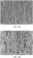
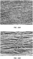
- Rotational spinning may be configured to create mats, tubes, or other structures comprised of elongate fibers, including nanofibers (i.e. fibers which are smaller than one micron in diameter) or microfibers (i.e. fibers which are between one micron and one millimeter in diameter).
- the fibers may be randomly disposed, while in other embodiments the alignment or orientation of the fibers may be somewhat controlled or follow a general trend or pattern. Regardless of any pattern or degree of fiber alignment, as the fibers are deposited on a collector or on previously deposited fibers; the fibers are not woven, but rather serially deposited on the collector or other fibers.
- rotational spinning may be configured to create a variety of structures, as used herein, the terms "mat” or “nonwoven mat or material” is intended to be broadly construed as referring to any such rotational spun structure, including tubes, spheres, and so on.
- the present disclosure relates to medical appliances which may have, in certain embodiments, metal scaffolding covered with at least one layer of rotational spun material, such as rotational spun polytetrafluoroethylene (PTFE). Additionally, the present disclosure relates to medical appliances formed of rotational spun materials which may not have scaffolding structures or have scaffolding structures which are not made of metal. It will be appreciated that, though particular structures and coverings are described below, any feature of the scaffolding or covering described below may be combined with any other disclosed feature without departing from the scope of the current disclosure.
- rotational spun material such as rotational spun polytetrafluoroethylene (PTFE).
- Figures 1A, 1B , 2A, and 2B schematically illustrate certain embodiments of rotational spinning apparatuses.
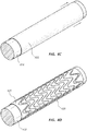
- Figures 3A and 3B illustrate an embodiment of a covered medical appliance.
- Figures 4A-4E illustrate certain steps in a process of manufacturing a multi-layered construct of rotational spun materials.
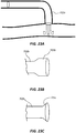
- Figure 5 illustrates an embodiment of a medical appliance which includes cuffs at each end of a stent.
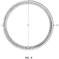
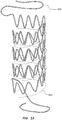
- Figures 6-10 illustrate aspects of frames configured for use in connection with medical appliances.
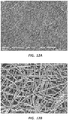
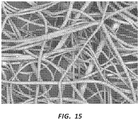
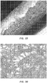
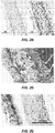
- Figures 11A-19 are scanning electron micrographs (SEMs) of exemplary rotational spun materials.
- SEMs scanning electron micrographs
- FIG 1A illustrates a rotational spinning apparatus 101.
- This Figure, as well as Figures 1B , 2A, and 2B , discussed below, are intended to schematically illustrate the operation of a rotational spinning apparatus, and not meant to limit the particular structure, shape, or arrangement of rotational spinning apparatus components within the scope of this disclosure.
- the illustrated apparatus 101 comprises a spinneret 110 disposed near the center of a generally circular collector 115.
- the collector 115 forms a ring around the spinneret 110.
- the spinneret 110 further comprises orifices 117 located around the circumference of the spinneret 110 and a reservoir 118.
- the apparatus 101 may be utilized to create a mat of rotational spun fibers deposited on the collector 115.
- the collector 115 may be configured such that structures such as rods, tubes, or spheres of rotational spun fibers are created.
- the apparatus 101 may be utilized to create a mat of rotational spun fibers by first filling the reservoir 118 with a flowable material.
- polymer dispersions including aqueous dispersions or polymer solutions may be used.
- the spinneret 110 may then be rotated such that the dispersion, or other flowable material, is forced out of the orifices 117 as illustrated by the arrows in Figure 1A .
- Molecules, including polymer chains may tend to disentangle and/or align as the material is forced through the orifice.
- the orifice 117 comprises a needle or nozzle that extends from the outside circumference of the spinneret 110.
- the orifice 117 may comprise a cannula configured with a quick connection, such as a luer connection, allowing for rapid exchange of various cannula sizes.
- drag or other aerodynamic forces acting on the stream or jet of material may cause the stream of dispersion to elongate and bend, forming a relatively small diameter fiber of material.
- drag may be a shear force with respect to the stream.
- certain components of the dispersion such as the dispersion medium or solvent, may partially or fully evaporate as the material is drawn into fibers.
- there may be no evaporation as the material is drawn into fibers.
- the fibers eventually contact, and are deposited on, the collector 115.
- the combination of forces described above may interact as the fibers are deposited, causing the fibers to be disposed in random patterns on the collector 115.
- air currents may be introduced (for example through the use of fans) to partially control the deposition of the fibers on the collector 115.
- the fibers may then be removed from the collector 115 and sintered, or sintered then removed.
- sintering may be applicable to PTFE fibers, including PTFE fibers spun from a dispersion. The sintering process may set or bond the structure of the mat and remove any remaining water or other dispersion medium or solvent.
- the mat may be treated at a first temperature to remove solvents and a second temperature to sinter the mat.
- a PTFE mat spun from an aqueous dispersion may be first treated at a temperature below the sintering temperature of PTFE in order to remove any remaining water.
- the mat may be heated to about 200 degrees C to remove any remaining water in the mat.
- other materials such as solvents or fiberizing agents may be evaporated or otherwise driven off at this stage.
- a PTFE dispersion may be mixed with polyethylene oxide (PEO) prior to rotational spinning the mat.
- PEO polyethylene oxide
- concentrations of PEO to 60 wt% PTFE dispersion from about 0.04 g/ml to about 0.12 g/ml, including from about 0.06 g/ml to about 0.08 g/ml may be used in some embodiments.
- very high or very low concentrations of PEO may lead to shrinkage during sintering or sputtering during rotational spinning of the material.
- Treating the spun mat at temperatures such as 200 degrees C may force off remaining PEO as well as water.
- the PTFE mat may then be sintered at about 385 degrees C.
- PTFE sintering may be completed at temperatures from about 360 degrees C to about 400 degrees C, and/or at temperatures in excess of the crystalline melt point of the PTFE (about 342 degrees C).
- the mat may only be heated to the sintering temperature, removing the remaining water and/or PEO while simultaneously sintering the PTFE.
- solvents or other materials may be removed by rinsing the mat.
- Sintering may set the structure of the mat even if the temperature at which the material is sintered is not sufficient to cause cross linking of the polymer chains.
- PTFE sintering may create solid, void free, PTFE fibers.
- Figure 1B is a top view of the rotational spinning apparatus 101 of Figure 1A , illustrating the spinneret 110, the collector 115, and the reservoir 118.
- potential arced paths of the streams of material interacting with drag forces are illustrated by arrows and dotted lines. These lines are exemplary and not intended to show the precise path of the fibers.
- the fibers may loop completely around the spinneret 110 before contacting the collector 115, including embodiments where the fiber path encircles the spinneret 110 more than one time before contacting the collector 115.
- the distance between the spinneret 110 and the collector 115 may impact the diameter of the fibers. In some embodiments, the longer the fibers are drawn out before contacting the collector 115, the smaller the resulting fiber diameters. Similarly, smaller distances may be configured to produce larger diameter fibers.
- Processes such as the exemplary process described above may be utilized to create structures comprised of small diameter fibers, including nanofibers.
- the fiber mat may then be incorporated into a medical appliance configured for implantation in the human body.
- Some such structures, including nanofiber structures may be configured to permit tissue ingrowth and/or endothelial growth or attachment on the mat.
- the mat may be configured with openings within the fibers or similar structures configured to permit interaction with tissue and/or cells.
- the percent porosity of a fiber mat, the thickness of the mat, and the diameter of the fibers comprising the mat may each be configured to create a fiber mat with desired properties, including mats that tend to permit or resist tissue ingrowth and/or endothelial growth or attachment.
- a number of variables may be controlled to affect the properties of a rotational spun mat. Some of these variables include: the rotational speed of the spinneret; the viscosity of the solution, dispersion, or other flowable material; the temperature of the spinneret; introduced air currents; the thickness of the mat; and so on.
- the melt flow index (MFI) of the material may also impact the nature of the spun mat.
- materials with an MFI of from about 1 g/10 min to about 5000 g/10 min, including from about 200 g/10 min to about 1500 g/10 min and from about 10 g/10 min to about 30 g/10 min, will tend to form fibers when spun.
- a rotational spun mat may be configured to resist tissue ingrowth into or through the mat.
- the mat may be configured with very small pores, or essentially no pores at all, thus preventing tissue ingrowth into or through the mat.
- Certain medical appliances may be constructed partially of rotational spun materials configured to permit tissue ingrowth and/or endothelial growth or attachment and partially of rotational spun materials configured to resist tissue ingrowth and/or attachment. Characteristics of the rotational spun fiber mat, such as porosity and average pore size, may be controlled during the rotational spinning process to create certain mats which permit tissue ingrowth and/or endothelial growth or attachment and other mats which resist or are impermeable to tissue ingrowth and/or attachment.
- a PTFE dispersion may be used to rotational spin a mat or another structure comprised of PTFE nanofibers.
- PEO may be added to the PTFE dispersion prior to rotational spinning the material.
- the PEO may be added as a fiberizing agent, to aid in the formation of PTFE fibers within the dispersion or during the process of rotational spinning the material.
- the PEO may more readily dissolve in the PTFE dispersion if the PEO is first mixed with water. In some examples this increased solubility may reduce the time needed to dissolve PEO in a PTFE dispersion from as long as multiple days to as little as 30 minutes.
- the material may then be sintered as further described below.
- the sintering process will tend to set or harden the structure of the PTFE.
- sintering may also eliminate the water and PEO, resulting in a mat of substantially pure PTFE.
- the mat may first be heat treated at a temperature below the sintering temperature of the PTFE, in order to remove water and/or PEO from the mat. In some embodiments this step may be completed at about 200 degrees C.
- the water, PEO, and PTFE amounts may be controlled to optimize the viscosity, PEO/PTFE ratio, or other properties of the mixture.
- adding water to the PEO before mixing with the PTFE dispersion may aid in reducing the number of solid chunks in the mixture, lower the preparation time for the mixtures, and reduce the time needed for the combined mixture to solubilize.
- a variety of materials may be rotational spun to form structures for use in medical appliances.
- Exemplary materials which may be rotational spun for use in implantable appliances include PTFE, fluorinated ethylene propylene (FEP), Dacron or Polyethylene terephthalate (PET), polyurethanes, polycarbonate polyurethanes, polypropylene, Pebax, polyethylene, biological polymers (such as collagen, fibrin, and elastin), and ceramics.
- additives or active agents may be integrated with the rotational spun materials, including instances where the additives are directly rotational spun with other materials.
- additives may include radiopaque materials such as bismuth oxide, antimicrobial agents such as silver sulfadiazine, antiseptics such as chlorhexidine or silver and anticoagulants such as heparin.
- Organic additives or components may include fibrin and/or collagen.
- a layer of drugs or other additives may be added to a rotational spun appliance during manufacture.
- some appliances may be constructed with a combination of synthetic components, organic components, and/or active ingredients including drugs, including embodiments wherein an appliance is comprised of alternating layers of these materials.
- a medical appliance may consist of layers of rotational spun materials configured to control the release of a drug or another active layer disposed between such layers.
- Active layers or ingredients such as drugs or other active agents may be configured to reduce or otherwise modify or influence the biological response of the body to the implantation of the medical appliance.
- the material supplied to the reservoir 118 may be continuously supplied (for example by a feed line), including embodiments where the reservoir is pressurized or supplied by a pressurized source. Further, in some embodiments the material may be heated near or above its melting point prior to rotational spinning, including embodiments wherein the material is melted and not dispersed in a solvent. Thus, in some embodiments, rotational spinning molten material does not include the use of solvents; therefore there is no need to remove solvents from the mat at a later step in the process. In some instances the material may be supplied to the reservoir as pellets which are heated and melted within the reservoir.
- the collector 115 may have an electrostatic charge.
- rotational spun structures may be combined with electrospun structures, including embodiments where some layers of material are rotational spun and some electrospun, but both deposited on the same substrate or construct. Electrospinning, and its use in connection with medical appliances, is described in U.S. Patent Application No. 13/360,444, filed on January 27, 2012 and titled "Electrospun PTFE Coated Stent and Method of Use,".
- FIG. 2A and 2B another schematic embodiment of a rotational spinning apparatus 201 is illustrated.
- Figures 2A and 2B illustrate an apparatus analogous to that shown in Figures 1A and 1B . It will be appreciated by one of skill in the art having the benefit of this disclosure that analogous components of the two apparatuses may be interchangeable and that disclosure provided in connection with each embodiment may be applicable to the other and vice versa.
- FIG 2A is a perspective view of the rotational spinning apparatus 201 while Figure 2B is a top view of the same.
- the rotational spinning apparatus 201 includes a spinneret 210 comprising a reservoir 218 and orifices 217.
- the collector 115 is configured as a plurality of cylindrical mandrels 216.
- the plurality of mandrels 216 are collectively designated as a collector 215, but individually designated by the numeral 216.
- collector as used in connection with Figures 1A-2B , and indicated by numerals 115 and 215, is intended to broadly refer to any collection device or apparatus without defining a particular size, shape, or orientation.
- the collector may be configured as a ring, such as the collector 115 illustrated in Figures 1A and 1B .
- the collector 215 may be a plurality of cylinders as shown in Figures 2A and 2B .
- the collector may comprise a rotating belt (not shown), configured to facilitate rotational spinning of a continuous sheet of material.
- Embodiments configured to form a continuous sheet of rotational spun material may be configured to produce mats, including mats from about one meter to about 9 meters in width, such as mats of about 3 meters in width. Also mats from about one foot wide to about one meter wide (as well as larger or smaller mats) may be formed.
- a sintering oven may be positioned such that as the mat moves away from the spinneret (on the belt) the mat enters the oven and is sintered. The sintered mat may then be collected onto a spool. Further, in some embodiments, the entire spool may then be cut into smaller widths, forming strips of material. For example, strips from about 0.3 cm (0.1 inch) wide to about 5 cm (2 inches) wide may be formed.
- Such strips may be utilized for the construction of tubular appliances by wrapping the strips around a mandrel.
- the strips may overlap and/or may be wound such that the tube formed does not have a distinct seam along the length of the tube.
- the mat may be wound in multiple layers around the mandrel. Further, the mat formed may be relatively thin, or film-like. The thickness of the covering formed on the mandrel (and other characteristics such as porosity) may be controlled by the number of layers of film wound onto the mandrel.
- rotational spun tubular medical devices such as stents
- medical devices which comprise a single lumen which splits or bifurcates into two or more lumens are within the scope of this disclosure.
- medical appliances comprising a main lumen with one or multiple branch lumens extending from the wall of the main lumen are within the scope of this disclosure.
- a thoracic stent - configured for deployment within the aorta - may comprise a main lumen configured to be disposed in the aorta and branch lumens configured to extend into side branch vessels originating at the aorta.
- such stents may alternately be configured with access holes in the main lumen configured to allow access (possibly for additional stent placement) and flow from the main vessel to any branch vessels extending there from.
- a bifurcated medical appliance may be manufactured by first creating a bifurcated mandrel in which the bifurcated mandrel portions are removable from the portion of the mandrel coinciding with the main lumen.
- the leg or branch portions of the mandrel may be splayed 180 degrees apart with a common axis of rotation.
- the entire mandrel may form a T-shape. The entire mandrel may then be rotated about the axis of the leg portions and rotational spun fibers collected on the leg portions of the mandrel.
- the mandrel may then be oriented to rotate about the axis of the main lumen portion of the mandrel, and any unwanted fibers disposed while spinning on the bifurcated leg portions may be wiped off.
- the mandrel may then be rotated about the axis of the main lumen portion and fibers collected on the main lumen portion of the mandrel.
- the entire mandrel may then be placed in an oven and sintered.
- the mandrel portions associated with the bifurcated legs may then be removed from the leg or branch portions of the appliance, and the single lumen mandrel portion subsequently removed from the spun appliance.
- the appliance may then be placed on or within a frame structure, such as a stent frame.
- a dip or film coating (such as of FEP or PTFE) may then be applied over the construct to create an impervious outside layer and/or to further bond the frame to the spun portion of the appliance.
- the sintering temperature may be from about 360 degrees C to about 400 degrees C, including at temperatures of about 385 degrees C or at temperatures above the crystalline melting temperature of the PTFE, or about 342 degrees C.
- sintering may be done at or above the crystalline melting temperature of other spun polymers.
- heat treating may be configured to remove PEO and/or water, in instances where the PTFE or other polymer was combined with such elements prior to spinning the mat.
- the mandrels 216 may be disposed about the spinneret 210 in a generally circular configuration. In some embodiments, the mandrels 216 may be stationary while in other embodiments the mandrels 216 may be configured to rotate about their axes. In some such embodiments the mandrels 216 may each be driven by the same belt, allowing each to maintain the same rotational speed. In other embodiments some or all of the mandrels 216 may be independently driven.
- the mandrels 216 are disposed vertically, or such that the axis of each mandrel is substantially parallel to the axis of rotation of the spinneret. In another exemplary embodiment, one or more of the mandrels 216 may be disposed horizontally, or such that the axis of those mandrels is substantially orthogonal to the axis of rotation of the spinneret. In some embodiments, the axis of the mandrel 216 may be generally parallel to the axes of fibers being spun. Horizontally disposed mandrels 216 may be configured to produce mats having generally less fiber alignment than vertical mandrels. Horizontal mandrels may further be configured to produce mats with relatively uniform thickness around the mandrel.
- mandrels disposed in any relative position with respect to the axis of the spinneret may comprise mandrels disposed in any relative position with respect to the axis of the spinneret.
- Mandrels mounted in any disposition may be configured as stationary collection devices or configured to rotate. Additionally, combinations of mandrels in a variety of positions may be used simultaneously.
- one or more mandrels 216 may be configured for use in connection with a vacuum system. For example, openings in the surface of the mandrel, such a micro-porous mandrels 216, may tend to draw fibers toward the mandrel in instances where the interior of the mandrel 216 has lower pressure than the exterior of the mandrel 216.
- each mandrel 216 may tend to deposit the fibers around the entire surface of the mandrel.
- a seamless tube of nanofiber material may form on each mandrel 216.
- the density of the fibers, the thickness of the mat, and other characteristics may be controlled by such variables as the distance from the spinneret 210 to the mandrels 216, the rotational speed of the spinneret 210, the rotational speed of the mandrels 216, the orientation of the mandrels 216, the characteristics of the solution being spun, and so forth.
- mats of rotational spun material formed on a spinning mandrel 216 may thus comprise a tubular membrane having no seam and substantially isotropic properties.
- the collection mandrel 216 may rotate at rates between about 1 RPM and about 2000 RPM during the rotational spinning process, including rates from about 1000 RPM to about 1500 RPM, including about 1500 RPM, or about 50 RPM to about 300 RPM, including about 150 RPM.
- the rotational speed of one or more collection mandrels may be related to the rate at which the apparatus produces fibers. For example, in some embodiments, faster mandrel rotational speed may be correlated with higher total fiber production rates for the apparatus.
- controlling the rotational speed of the mandrels 216 may influence both the density of the mat formed on the mandrels 216 and the general alignment of fibers in the mat. For instance, in some embodiments utilizing vertical mandrels, the faster the mandrel 216 is spinning the more the fibers may tend to be deposited in-line with other fibers. Further, the relative density of the fibers, for example, as measured by percent porosity, may be controlled in part by the rotational speed of the mandrels 216.
- Figures 13A-14B discussed below, are SEMs of exemplary mats rotational spun onto rotating mandrels.
- the fibers may be sintered.
- a scaffolding structure such as a stent wire, may also be on the mandrel 216, and the nanofibers rotational spun directly onto the mandrel 216 and scaffolding structure.
- Figures 3A and 3B illustrate an exemplary medical appliance: a stent 302.
- the stent 302 comprises a scaffolding structure 320 and a covering comprising an inner layer 325, an outer layer 330, and a tie layer 335.
- a stent covering may have more or fewer layers than the illustrated embodiment, including embodiments with only one covering layer.
- disclosure recited herein with respect to specific medical appliances, such as stents may also be applicable to other medical appliances.
- the cover of the stent 302 of Figure 3A comprises a flat end 321 and a scalloped end 322.
- the cover of the stent 302 is cut substantially perpendicular to the longitudinal axis of the stent 302.
- the cover of the stent 302 comprises cut away, or scalloped, portions at the end of the stent 302.
- Scalloped ends may be configured to reduce infolding of the stent cover at the ends.
- a stent may have a larger diameter than a vessel in which it is deployed. Thus, the vessel may partially compress the stent radially.
- this radial compression may create folds or wrinkles in flat cut stent covers. These folds may then impede blood flow or lead to clotting within the vessel.
- Scalloped ends may reduce the occurrence of infolding at the end of a radially compressed stent. It is within the scope of this disclosure to use either type of end on any end of any stent.
- Membranes composed of rotational spun mats may have a microstructure composed of many fibers crossing each other at various and random points.
- the rotational spinning process may control the thickness of this structure and thereby, the relative permeability of the mat.
- the mat may both increase in thickness and decrease in permeability (due to successive layers of strands occluding the pores and openings of layers below). Certain details of this microstructure are shown in Figures 11A-19 , which are discussed in more detail below.
- Mats produced in connection with the present disclosure may be described by three general parameters: percent porosity, mat thickness, and fiber diameter. Each of these parameters may impact the nature of the mat, including the tendency of the mat to permit tissue ingrowth and/or endothelial attachment or the tendency of the mat to resist tissue ingrowth or endothelial attachment. Each of these parameters may be optimized with respect to each other to create a mat having particular characteristics.
- Percent porosity refers to the percent of open space to closed space (or space filled by fibers) in a fiber mat. Thus, the more open the mat is, the higher the percent porosity measurement.
- percent porosity may be determined by first obtaining an image, such as an SEM, of a rotational spun material. The image may then be converted to a "binary image," or an image showing only black and white portions, for example. The binary image may then be analyzed and the percent porosity determined by comparing the relative numbers of each type of binary pixel. For example, an image may be converted to a black and white image wherein black portions represent gaps or holes in the rotational spun mat while white portions represent the fibers of the mat. Percent porosity may then be determined by dividing the number of black pixels by the number of total pixels in the image. In some instances, a code or script may be configured to make these analyses and calculations.
- percent porosities from about 30% to about 80% may be configured to permit tissue ingrowth into the layer and/or permit endothelial growth or attachment on the layer, including mats of about 40% to about 60%, mats of about 45% to about 50%, or mats of about 50% porosity. Less open layers may be configured to resist such ingrowth and/or attachment. Because the fibers comprising the mat are deposited in successive layers, the second parameter, mat thickness, may be related to porosity. In other words, the thicker the mat, the more layers of fibers, and the less porous the mat may be.
- mats from about 20 micrometers to about 100 micrometers may be configured for use in connection with the present disclosure, including mats from about 40 micrometers to about 80 micrometers.
- the third parameter, fiber diameter may be a measurement of the average fiber diameter of a sample in some instances. In some embodiments fiber diameters from about 50 nanometers to about 3 micrometers may be used in connection with the present disclosure. Notwithstanding these or other specific ranges included herein, it is within the scope of this disclosure to configure a mat with any combination of values for the given parameters.
- the "average pore size" of the mat may be used as an alternate or additional measurement of the properties of the mat.
- the complex and random microstructure of rotational spun mats presents a challenge to the direct measurement of the average pore size of the mat.
- Average pore size can be indirectly determined by measuring the permeability of the mat to fluids using known testing techniques and instruments. Once the permeability is determined, that measurement may be used to determine an "effective" pore size of the rotational spun mat.
- the "pore size" of a rotational spun mat refers to the pore size of a membrane which corresponds to the permeability of the rotational spun mat when measured using ASTM standard F316 for the permeability measurement.
- a medical appliance such as stent 302 with an outer layer 330 which is substantially impermeable.
- Such a layer may decrease the incidence of lumen tissue surrounding the stent growing into or attaching to the stent. This may be desirable in applications where the stent is used to treat stenosis or other occlusions; an impermeable outer layer may prevent tissue from growing into or through the material toward or into the lumen of the stent and reblocking or restricting the body lumen.
- a substantially impermeable outer layer may be produced by using rotational spun mats with a percent porosity from about 0% to about 50%, including about 25%; a thickness from about 20 micrometers to about 100 micrometers, including from about 40 micrometers to about 80 micrometers; and fiber diameters from about 50 nanometers to about 3 micrometers.
- a substantially impermeable mat may have an average pore size of about 0 microns to about 1.5 microns.
- the impermeable layer may have an average pore size of less than about 0.5 micron.
- the impermeable layer may have an average pore size of less than about 1 micron.
- the impermeable layer may be a layer other than the outer layer, such as a tie layer, an intermediate layer, or an inner layer.
- a medical appliance such as stent 302 may be covered with a rotational spun PTFE inner layer 325 and a rotational spun PTFE outer layer 330.
- the outer layer 330 may be configured to be substantially impermeable to tissue ingrowth and/or attachment.
- the impermeability of the stent may be provided by a tie layer 335 disposed between the outer layer 330 and the inner layer 325.
- a substantially impermeable layer may be formed of FEP which is applied, for example, as a film or dip coating between rotational spun layers of PTFE.
- FEP may be rotational spun with a small average pore size to create a substantially impermeable layer.
- both the outer layer 330 and the tie layer 335 may be configured to be substantially impermeable.
- Dip coatings may be applied by dipping a portion of a layer or construct in a polymer dispersion.
- a PTFE layer may be dip coated on a construct by adding 20 ml of water to 50 ml of a 60 wt% PTFE dispersion to thin the dispersion.
- a fiber mat may then dipped in the solution to coat the mat.
- the dip coat may then sintered at 385 degrees C for 15 minutes.
- concentrations of PTFE dispersions for dip coatings are also within the scope of this disclosure.
- an FEP layer may be dip coated on a construct by adding 20 ml of water to 50 ml of a 55 wt% dispersion to thin the dispersion.
- a fiber mat may then dipped in the solution to coat the mat.
- the dip coat may then cooked, for example, at 325 degrees C for 15 minutes.
- Other concentrations of FEP dispersions for dip coatings are also within the scope of this disclosure.
- polymer dispersions may be sprayed or otherwise applied onto a surface (such as a fiber mat) to coat the surface. Such coatings may be heat treated after application.
- more or less water may be added to similar amounts and concentrations of the dip dispersions above to thin the dispersions.
- substances other than, or in addition to, water may be used to thin a dispersion for dip coating.
- a surfactant or a solvent may be used. In some such cases the surfactant or solvent may later be removed from the construct, including embodiments where it is allowed to evaporate when the coat is sintered or cooked. Alcohols, glycols, ethers, and so forth may be so utilized.
- a medical appliance such as stent 302 with an outer layer 330 which is more porous.
- a porous outer layer 330 may permit healing and the integration of the prosthesis into the body. For instance, tissue of the surrounding lumen may grow into the porous outer diameter or attach to the outer diameter layer. This tissue ingrowth may permit, modulate, and/or influence healing at the therapy site.
- a porous outer layer 330 may be formed of rotational spun PTFE.
- a relatively porous inner layer 325 may be desirable. This layer may or may not be used in conjunction with a substantially impermeable outer layer 330.
- a relatively porous inner layer may permit tissue ingrowth and/or endothelial attachment or growth on the inside diameter of the stent 302 which may be desirable for any combination of the following: healing, biocompatibility, prevention of thrombosis, and/or reducing turbulent blood flow within the stent.
- the inner layer may be comprised of a mat, such as a rotational spun PTFE mat, having a percent porosity of about 40% to about 80%, including about 50%; a thickness of about 20 micrometers to about 100 micrometers, including from about 40 micrometers to about 80 micrometers; and fiber diameters from about 50 nanometers to about 3 micrometers.
- a mat such as a rotational spun PTFE mat, having a percent porosity of about 40% to about 80%, including about 50%; a thickness of about 20 micrometers to about 100 micrometers, including from about 40 micrometers to about 80 micrometers; and fiber diameters from about 50 nanometers to about 3 micrometers.
- the mat may be comprised of a rotational spun mat, such as PTFE, with an average pore size of about 1 micron to about 12 microns, such as from about 2 microns to about 8 microns, or from about 3 microns to about 5 microns, or alternatively from about 3.5 microns to about 4.5 microns.
- a rotational spun mat such as PTFE
- Figure 3B illustrates a cross sectional view of the stent 302 of Figure 3A , again comprising a scaffolding structure 320 and covering comprising an inner layer 325, an outer layer 330, and a tie layer 335.
- the tie layer 335 is shown at the same "level" as the scaffolding structure 320, the tie layer may be above or below the scaffolding in some embodiments.
- each layer of the covering may be disposed so that there are no voids between layers.
- the tie layer 335 may be configured to promote bonding between the outer layer 330 and the inner layer 325. In other embodiments the tie layer 335 may further be configured to provide certain properties to the stent 302 as a whole, such as stiffness or tensile strength.
- the tie layer 335 may thus be configured as a reinforcing layer.
- expanded PTFE ePTFE
- ePTFE may be configured as a reinforcing layer.
- ePTFE may be anisotropic, having differing properties in differing directions. For example, ePTFE may tend to resist creep in the direction the ePTFE membrane was expanded.
- a reinforcing layer of ePTFE may be oriented to increase strength, resist creep, or impart other properties in a particular direction.
- ePTFE may be oriented such that the expanded direction is aligned with an axial direction of a medical device, a transverse direction, a radial direction, at any angle to any of these directions, and so forth.
- multiple layers of ePTFE may be disposed to increase strength, resist creep, or impart other properties in multiple directions.
- the reinforcing layer may or may not be impermeable.
- the tie layer 335 may be configured to create an impermeable layer between the two porous layers.
- the stent may permit tissue ingrowth, tissue attachment and/or healing on both the inner and outer surfaces of the stent while still preventing tissue outside of the stent from growing into the lumen and occluding the lumen.
- tie layers may be configured to create a mid-layer portion of a construct, the tie-layer configured to inhibit tissue ingrowth into the layer or to be impervious to tissue migration into or through the layer or to substantially inhibit tissue migration.
- the tie layer 335 may be configured to be impervious or substantially impervious to fluid migration across the tie layer 335.
- constructions comprising one or more porous layers may allow fluid to cross the porous layer.
- a porous layer may allow blood to leak across the layer or may allow certain smaller components of the blood to cross the layer while containing larger components, effectively filtering the blood. In some instances this filtration or ultrafiltration may allow components such as plasma to cross the barrier while containing red blood cells, leading to seroma.
- a fluid impermeable tie layer may be configured to contain fluid within a medical device also comprised of porous layers.
- a tie layer may be both fluid impermeable and impervious to tissue ingrowth, or may be configured with either of these properties independent of the other. Constructs wherein any layer (other than, or in addition to a tie layer) is configured to be fluid impermeable and/or impervious to tissue ingrowth are also within the scope of this disclosure. Thus, disclosure recited herein in connection with fluid impermeable and/or tissue impervious tie layers may be analogously applied to impermeable layers at various locations within a construct.
- the tie layer may include any thermoplastic and may or may not be rotational spun.
- the tie layer may be expanded PTFE.
- it may be rotational spun PTFE.
- it may be FEP, including rotational spun FEP and FEP applied as a film or dip coating.
- the tie layer may include any of the following polymers or any other thermoplastic: dextran, alginates, chitosan, guar gum compounds, starch, polyvinylpyridine compounds, cellulosic compounds, cellulose ether, hydrolyzed polyacrylamides, polyacrylates, polycarboxylates, polyvinyl alcohol, polyethylene oxide, polyethylene glycol, polyethylene imine, polyvinylpyrrolidone, polyacrylic acid, poly(methacrylic acid), poly(itaconic acid), poly(2-hydroxyethyl acrylate), poly(2-(dimethylamino)ethyl methacrylate-co-acrylamide), poly(N-isopropylacrylamide), poly(2-acrylamido-2-methyl-l-propanesulfonic acid), poly (methoxyethylene), poly(vinyl alcohol), poly(vinyl alcohol) 12% acetyl, poly(2,4-dimethyl-6-triazinylethylene), poly(3morpholiny
- the tie layer 335 may or may not be rotational spun. Further, in certain embodiments the stent 302 may include two or more tie layers.
- the tie layer 335 may be formed in any manner known in the art and attached to the inner 325 and outer 330 layers in any manner known in the art.
- the tie layer 335 may comprise a sheet of material which is wrapped around the inner layer 325 or a tube of material which is slipped over the inner layer 325 which is then heat shrunk or otherwise bonded to the inner 325 and outer 330 layers.
- the tie layer may be rotational spun directly onto the inner layer 325, the scaffolding, or both. In some instances the tie layer 335 may be melted after the stent 302 is constructed to bond the tie layer 335 to adjacent layers of the stent covering.
- tie layers may be configured to change the overall properties of the medical appliance.
- a cover or construct comprised solely of rotational spun PTFE (of the desired pore size) may not have desired tensile or burst strength.
- a tie layer comprised of a relatively stronger material may be used to reinforce the PTFE inner layer, the PTFE outer layer, or both.
- FEP layers may be used to increase the material strength of the cover.
- the tie layer may also be configured as a portion of the construct configured to be impervious to tissue ingrowth or migration.
- one or more layers of rotational spun PTFE may be used in connection with a scaffolding structure other than that shown herein.
- the disclosure above relating to covers, layers, tie layers, and related components is applicable to any type of scaffolding structure as well as to stents or grafts with no separate scaffolding structure at all.
- Figures 4A-4E illustrate certain steps in a process of manufacturing a multilayer construct for use in connection with a medical appliance. More specifically, these figures illustrate a process of creating a stent covered with rotational spun material. Again, this disclosure is equally relevant to all medical appliances which may comprise a cover or multilayered construct, including grafts, patches, stents, and so on. Additionally, as suggested in the additional examples disclosed below, the illustrated steps may be optional in some instances or augmented by additional steps in others.
- Figure 4A illustrates a covering inner layer 425 disposed around a mandrel 416.
- the inner layer 425 may be rotational spun directly onto the mandrel 416, including instances wherein the mandrel 416 was rotating during the process.
- the inner layer 425 was rotational spun onto a rotating mandrel 416 such that the resultant tube of material has no seam.
- the inner layer 425 may then be sintered.
- the membrane may be sintered at temperatures of about 385 degrees C, including temperatures from about 360 degrees C to about 400 degrees C.
- Sintering may tend to set the structure of the PTFE, meaning sintering reduces the softness or flowability of the PTFE. Furthermore, as discussed above, sintering or otherwise heat treating the mat may evaporate any water or PEO mixed with the PTFE, resulting in a material comprised substantially of pure PTFE.
- the tube of material may be removed from the mandrel 416, as illustrated in Figure 4B .
- the inner layer 425 may be "peeled" from the mandrel 416 to initially break any adherence of the inner layer 425 to the mandrel 416.
- the inner layer 425 may also be removed by pushing the covering with respect to the mandrel 416, causing the material to bunch as it is removed from the mandrel 416.
- low friction coatings may alternatively or additionally be applied to the mandrel 416 before the inner layer 425 is rotational spun.
- the inner layer 425 may then be reapplied to the mandrel 416, by slipping the inner layer 425 over the mandrel 416, as illustrated in Figure 4C .
- a wire scaffolding 420 can be formed over the mandrel 416 and the inner layer 425, as shown in Figure 4D .
- Figure 4E illustrates an outer layer 430 of material which may then be rotational spun onto the scaffolding 420 and the inner layer 425. The entire construct may then be sintered. Additional layers may also be added through similar processes.
- one or more layers may be applied by wrapping strips or mats of material around the mandrel 416 and/or the other layers. Further, some of the layers may be applied by spray or dip coating the mandrel 416 and/or the other layers. It is within the scope of this disclosure to vary the process above to apply to any of the layers, or any additional layers, using any method disclosed herein.
- a stent may be comprised of an inner layer of rotational spun PTFE, a tie layer of FEP, and an outer layer of PTFE.
- the properties of each of these layers, including percent porosity, mat thickness, fiber diameter, and/or average pore size may be controlled to form a covering layer that inhibits the growth of tissue into or through a particular layer or that permits endothelial growth or attachment on a particular layer.
- the inner layer of PTFE may be spun on a mandrel, sintered, removed from the mandrel, and replaced on the mandrel then a scaffolding structure applied around the inner layer (analogous to the procedure illustrated in Figures 4A-4D ).
- the FEP tie layer may then be applied by dipping, spraying, applying a film layer, electrospinning, rotational spinning, extrusion, or other processing.
- the FEP layer may be heated such that the FEP becomes soft, in some cases flowing into open spaces in adjacent PTFE layers. This may tie the FEP layer to adjacent PTFE layers. In some instances, heating the construct to about 325 degrees C may allow the FEP to partially flow into openings in adjacent PTFE layers, without the FEP completely flowing through the PTFE mat.
- Figure 20 and Example 10, included below, provide one example of an FEP layer partially melting into a rotational spun PTFE mat.
- an inner layer of PTFE may be rotational spun on a mandrel, sintered, removed, and replaced, then a scaffolding structure applied around the inner layer.
- An FEP tie layer may then be applied as a film layer. In some instances this tie layer may be "tacked" into place, for example, by a soldering iron.
- a tube of PTFE (which may be formed separately by rotational spinning onto a mandrel and sintering) may then be disposed over the FEP film layer.
- the entire construct may then be pressured, for example, by applying a compression wrap.
- this wrap may comprise any suitable material, including a PTFE-based material.
- a Kapton film may be wrapped around the construct before the compression wrap, to prevent the construct from adhering to the compression wrap.
- the compressed layers may then be heated above the melting temperature of the FEP tie layer, but below the sintering temperature of the PTFE.
- the melt temperature of the FEP may be from about 264 degrees C to about 380 degrees C, including about 325 degrees C.
- PTFE may be sintered at temperatures from about 360 degrees C to about 400 degrees C.
- the entire construct may be heated to an appropriate temperature such as about 325 degrees C. In some embodiments the construct may be held at this temperature for about 15 to about 20 minutes. Heating the FEP layer to about 325 degrees C may allow the FEP layer to remain substantially impervious to tissue ingrowth and/or attachment, creating a "barrier" layer within the construct, while still adhering the FEP to adjacent layers of PTFE.
- heating the construct to higher temperatures may be configured to allow the FEP to flow around the PTFE such that the entire construct has a higher degree of porosity and the FEP layer is not as impervious to ingrowth.
- the joining of the FEP tie layer to the PTFE outer and inner cover layers may increase the strength of the finished covering.
- the construct may then be cooled and the compression wrap and the Kapton film discarded.
- the construct may then be removed from the mandrel.
- a stent formed by the exemplary process described above may be configured with desired characteristics of porosity and strength.
- the FEP material may coat the PTFE nanofibers but still allow for sufficient porosity to permit tissue ingrowth and/or endothelial attachment or growth.
- the degree to which the FEP coats the PTFE may be controlled by the temperature and time of processing. The lower the temperature and/or the shorter the time the construct is held at temperature, the less the FEP may flow.
- a tie layer of FEP which is impervious to tissue ingrowth into or through the layer may be formed by heating the construction only to about 270 degrees C.
- Figure 5 illustrates a stent 502 which comprises a scaffolding structure 520 and a covering 524.
- the covering 524 may be comprised of any combination of layers disclosed herein.
- the stent 502 of Figure 5 includes a cuff 540 at both ends of the stent 502. In other embodiments a cuff 540 may only be located at one end of the stent 502.
- the cuff 540 may comprise an additional covering layer on the outside diameter of the stent 502, disposed adjacent to one or both ends of the stent 502.
- the cuff 540 may be configured to promote tissue ingrowth, attachment, and/or incorporation into the cuff 540; for example the cuff 540 may be more porous than an outer layer of the covering 524 of the stent 502. Factors such as porosity, type of covering or coating, type of material, use of organic material, and/or use or composite materials formed of synthetic material and organic material may be used to create a cuff 540 configured for tissue ingrowth.
- the cuff 540 may be configured to promote tissue ingrowth and/or the growth or attachment of endothelial cells at one or both ends of the stent 502.
- the cuffs 540 may tend to "anchor" the ends of the stent 502 with respect to the vessel walls, reducing the relative movement of the stent ends with respect to the vessel walls. Such a reduction in movement may lessen irritation of the vessel by the stent ends, minimizing complications such as stenosis.
- Cuffs 540 may be configured for use in CVO type applications in some instances.
- a band of porous material analogous to the stent cuff 540 illustrated may be coupled to any medical appliance to anchor a portion of such a device.
- the outer layer of the covering 524 of the stent 502 may be relatively non-porous to inhibit tissue ingrowth into or through the outer layer, but the cuff 540, disposed about the outer layer, may provide a section near each end at which some tissue ingrowth, attachment, or incorporation may occur.
- the cuff 540 may be comprised of a rotational spun material, such as PTFE, and may be bonded to the outer covering layer through any method, including methods of multilayer device construction described herein.
- a layer of FEP may be disposed between the outer covering layer and the cuff 540 and heated to bond the layers.
- the cuff 540 may comprise a collagen layer which is coupled to the stent. Further, a co-rotational spun collagen and PTFE cuff 540 may be utilized.
- the current disclosure relates to medical appliances, including stents, which may comprise a frame structure provided in connection with one or more coverings or coatings.
- stents which may comprise a frame structure provided in connection with one or more coverings or coatings.
- any feature of the frames or coverings and/or coatings described herein may be combined with any other disclosed feature without departing from the scope of the current disclosure.
- certain figures reference below show a metal frame without any covering or coating; the features described and illustrated in those figures may be combined with any combination of coverings or coatings disclosed herein.
- the term "frame” refers to a support structure for use in connection with a medical appliance.
- a scaffolding structure such as that described in connection with Figures 4A-4E , above, is an example of a frame used in connection with a medical appliance.
- a medical appliance - such as a stent - may comprise frame alone, with no covering, coating, or other components.
- a hernia patch may comprise a two layered construction, which one side of the patch configured to allow tissue ingrowth and/or attachment (for bonding and healing) and the other side configured to resist such ingrowth and/or attachment (to make the second side "slippery" with respect to surrounding tissue.
- a patch as described above may also comprise a tie layer disposed between the two exterior layers. The tie layer may be configured resist tissue ingrowth or attachment into or through the patch and/or to provide mechanical properties such as strength to the construct.
- Figures 6, 7A, and 7B show views of a possible embodiment of a frame for use in connection with a medical appliance such as a stent or graft.
- Figure 7C is an alternative configuration of a portion of the frame structure.
- Figures 8 and 9 are views of one embodiment of a frame which includes flared ends.
- Figure 10 illustrates one embodiment of how a wire may be shaped to form a frame.
- Frames for use in connection with medical appliances may be fabricated or formed into particular geometries through a variety of means.
- a frame may be cut from a single tube of material, including embodiments wherein the frame is first laser cut, then expanded.
- the frame may be molded, including embodiments wherein the frame is molded from a polymeric material.
- powder metallurgical processes such as powdered compression molding or direct metal laser sintering, may be used.
- Figure 6 illustrates a front elevation view of an embodiment of a frame.
- the illustrated embodiment depicts one embodiment of a configuration for a metal wire 650 forming a frame.
- the frame may consist of a single continuous wire.
- the frame structure may consist of a wire 650 shaped to form the frame.
- the wire 650 may be shaped in a wave-type configuration, the waves defining apexes 652 and arms 654 of the frame structure.
- the frame may further be coupled to a covering layer (not pictured). Additionally, in some embodiments, any covering as disclosed herein may be applied to any type of frame, for example, laser cut frames, polymeric frames, wire frames, and so forth.
- the frame may be designed such that the midsection is "harder” than the ends.
- the “hardness” of the frame refers to the relative strength of the structure (e.g., its compressibility). A harder portion of the frame will have greater strength (i.e., exert a greater radial outward force) than a softer portion.
- the midsection is harder than the proximal and distal end sections which are relatively softer.
- a frame may be configured to be flexible to facilitate the ability of the device to conform to the native anatomy at which the device is configured for use.
- covered devices may be configured with covers which conform to the native anatomy at a therapy site.
- the frame may be configured to allow the entire device to be crimped into a relatively low-profile configuration for delivery.
- devices of a certain diameter or constrained profile are more feasible for delivery at certain vascular or other access points than others.
- a device configured for insertion via the radial artery may be relatively smaller than devices configured for insertion via the generally larger femoral artery.
- a frame may be configured to be crimped into a particular profile to enable potential access at various or desired access points.
- devices having no frame may be configured to be disposed in a particular profile to facilitate access and delivery.
- apex to apex distance designated as H x in Figures 6 and 7A
- arm length designated as A x in Figures 6 and 7A
- apex radius designated as R x in Figure 7A
- the diameter of the wire 650 may or may not be constant at different points on a frame.
- each distance identified as “H” refers to an apex to apex distance with subscripts 1, 2, 3, etc., signifying the apex to apex distance at a particular point. It will be appreciated that these subscript designations do not necessarily refer to a specific distance, but may be used relatively (i.e., H 1 may be designated as smaller than H 2 without assigning any precise value to either measurement). Further, as will be apparent to one skilled in the art having the benefit of this disclosure, an analogous pattern of measurements and subscripts is employed for other parameters described herein, for example A x and R x .
- the overall frame design may be configured to optimize desired radial force, crush profile, and strain profile.
- the frame design parameters may each be configured and tuned to create desired characteristics.
- the strain profile may be configured to be less than the failure point for the material being used.
- a first parameter, the apex to apex distance, is designated as H x .
- This measurement signifies the distance between a first apex and a second apex where both apexes substantially lie along a line on the outside diameter of the frame which is co-planar with, and parallel to, the longitudinal axis of the frame.
- H x may be constant along the entire length of the frame.
- the length of the frame may be divided into one or more "zones" where H x is constant within a zone, but each zone may have a different H x .
- H x may vary along the entire length of the frame.
- H x may be configured, in connection with the other design parameters, to determine the properties of the frame. Generally, regions of the frame with a smaller H x value will be harder than regions with a larger H x value.
- H 1 designates the apex to apex distance in the midbody zone of the frame and H 2 designates the apex to apex distance in the flare zones of the frame.
- the apex to apex distance, H 2 is the same in both the flare zone near the distal end of the frame and the flare zone near the proximal end of the frame.
- H 1 may be smaller than H 2 , resulting in a frame that is relatively harder in the midbody and relatively softer on the ends.
- a frame with such properties may be utilized in applications where strength is necessary along the midbody, for example to treat a tumor or other occlusion, but the ends are configured to rest on healthy tissue where softer ends will minimize trauma to the healthy tissue.
- H 1 may be between about 2 mm and 30 mm, and H 2 between about 2.1 mm and 30.1 mm.
- H 1 may be between about 3 mm and 10 mm, and H 2 between about 3.1 mm and 10.1 mm, such as: 3 mm ⁇ H 1 ⁇ 8 mm and 3.5 mm ⁇ H 2 ⁇ 9 mm; 3 mm ⁇ H 1 ⁇ 6.5 mm and 4 mm ⁇ H 2 ⁇ 8 mm; or 3 mm ⁇ H 1 ⁇ 5 mm and 5.5 mm ⁇ H 2 ⁇ 6.5 mm.
- the change in apex to apex length may be correlated to the displacement of the apexes from the midpoint of the frame.
- the apex to apex length may increase incrementally as one moves away from the midpoint of the frame toward the ends in a manner that gives the frame the same geometry, and therefore the same properties, on either side of the midpoint of the length of the frame.
- different geometries may be utilized at any point along the length of the frame. It will be appreciated that the ranges of values for H x disclosed above apply analogously to embodiments where the frame has multiple apex to apex lengths.
- a frame may have an apex to apex length at midbody within one of the ranges disclosed above for H 1 , and the value of H x may vary incrementally, in steps, or some other pattern, along the length of the frame reaching an apex to apex length at the ends within the complementary range for H 2 .
- the value of H x may be small enough that adjacent coils are "nested" within each other.
- the apexes of a first helical coil may extend up into the spaces just below the apexes of the next adjacent coil.
- apexes of lower coils may extend a sufficient amount so as to be disposed between the arms of higher coils.
- the value of H x may be large enough that adjacent coils are completely separated.
- the number of wires at any particular cross section of the stent may be higher than a non-nested stent.
- Nested frames may create relatively higher strains in the frame when a stent comprised of the frame is loaded into a delivery catheter. In some instances the delivery catheter for a nested frame may therefore be relatively larger than a delivery catheter configured for a non-nested frame. Further, nested frames may be relatively stiff as compared to non-nested stents with similar parameters.
- frames with a hard midbody and soft ends may be desirable for a variety of applications.
- a basically "symmetric" frame may be desirable; in other words, a frame with certain properties at the midbody section and other properties at the ends, where the properties at both ends are substantially identical.
- other embodiments may have varied properties along the entire length of the frame.
- the effect of changing variables for instance the difference between H 1 and H 2
- a substantially symmetric stent as in Figure 6
- the same principles may be utilized to control the properties of a frame where the geometry varies along the entire length of the frame.
- a second parameter, arm length is designated as A x in Figures 6 and 7A .
- a x may be constant along the length of the frame, be constant within zones, or vary along the length of the frame. Variations in the length of A x may be configured in conjunction with variations in the other parameters to create a frame with a particular set of properties. Generally, regions of the frame where A x is relatively shorter will be harder than regions where A x is longer.
- the arm length A 1 near the midsection of the frame will be shorter than the arm length A 2 near the ends. This configuration may result in the frame being relatively harder in the midsection. In embodiments where soft ends and a hard midbody are desirable, A 1 may be between about 2 mm and 30 mm, and A 2 between about 2.1 mm and 30.1 mm.
- a 1 may be between about 2 mm and 10 mm, and A 2 between about 2.1 mm and 10.1 mm, such as: 2.5 mm ⁇ A 1 ⁇ 8 mm and 3 mm ⁇ A 2 ⁇ 9 mm; 3 mm ⁇ A 1 ⁇ 6 mm and 4 mm ⁇ A 2 ⁇ 7.5 mm; or 4 mm ⁇ A 1 ⁇ 5 mm and 5 mm ⁇ A 2 ⁇ 6 mm.
- the change in arm length may be correlated to the displacement of the arm from the midpoint along the frame.
- the arm length may increase incrementally as one moves away from the midpoint of the frame toward the ends in a manner that gives the frame the same geometry, and therefore the same properties, on either side of the midpoint of the length of the frame.
- different geometries may be utilized at any point along the length of the frame. It will be appreciated that the ranges of values for A x disclosed above apply analogously to embodiments where the frame has multiple arm lengths.
- a frame may have an arm length at midbody within one of the ranges disclosed above for A 1 , and the value of A x may vary incrementally, in steps, or some other pattern, along the length of the frame reaching an arm length at the ends within the complementary range for A 2 .
- a third parameter, the apex radius, is designated as R 1 in Figure 7A .
- R x may be configured in order to create desired properties in a frame.
- the inside radius of each apex may form an arc which has a substantially constant radius. As shown by a dashed line in Figure 7A , this arc can be extended to form a circle within the apex.
- the measurement R x refers to the radius of the arc and circle so described.
- the arms and apexes of the frame are formed by molding a wire around pins protruding from a mandrel.
- R x will be constant along the entire length of the frame, be constant within zones along the length of the frame, or vary along the entire length of the frame. Variations in the magnitude of R x may be configured in conjunction with variations in the other parameters to create a frame with a particular set of properties. Generally, regions of the frame where R x is relatively smaller will be harder than regions where R x is larger.
- R x may result in relatively lower strain in the wire frame when the frame is compressed, for example when the frame is disposed within a delivery catheter.
- wires of relatively larger diameters may result in relatively lower strain at or adjacent to the radius measured by R x when compressed, as compared to wires of smaller diameters.
- the strain may be optimized for a particular design by varying the value of R x and the diameter of the wire forming the frame.
- R x may take on a range of values depending on the application and the desired properties of the frame.
- R x may be between about 0.12 mm and 1.5 mm, including from about 0.12 to about 0.64 mm.
- R x may be between about 0.35 mm and 0.70 mm, such as: 0.35 mm ⁇ R x ⁇ 0.65 mm; 0.35 mm ⁇ R x ⁇ 0.6 mm; or 0.4 mm ⁇ R x ⁇ 0.5 mm.
- R x the disclosed ranges for R x apply whether the value of R x is constant along the length of the frame, whether the frame is divided into zones with different R x values, or whether R x varies along the entire length of the frame.
- Figure 7A illustrates a cutaway view of the front portions of two adjacent coils of a frame.
- the portions of the coils depicted are meant to be illustrative, providing a clear view of the three parameters H x , A x , and R x . It will be appreciated that all three of these parameters may be configured in order to create a frame with particular properties. Any combination of the values, ranges, or relative magnitudes of these parameters disclosed herein may be used within the scope of this disclosure.
- H 1 may be about 4 mm and H 2 about 5.9 mm;
- a 1 may be about 4.5 mm and A 2 about 5.6 mm; and
- R 1 about 0.5 mm.
- Figure 7B is a close up view of one end of a frame.
- Figure 7B illustrates one way in which the end 656 of the wire may be coupled to the frame.
- the wire may be disposed such that the final coil approaches and runs substantially parallel to the previous coil. This configuration results in the apex to apex distance between the two coils decreasing near the end 656 of the wire. In some embodiments this transition will occur along the distance of about 4 to 8 apexes along the length of the wire.
- the apex to apex distance will decrease from H 2 ' to a smaller distance which allows the end 656 of the wire to meet the prior coil (as illustrated in Figure 7B ) over the course of about 4 to 8 apexes.
- Figure 7C illustrates an alternative configuration of a portion of a frame.
- apexes 652' alternate in relative height along the length of the wire.
- the apexes form a pattern comprising a higher apex, a shorter apex, a higher apex, a shorter apex, and so on, around the helical coil.
- a frame may be configured with alternating apexes at one or both ends of the frame.
- a frame as shown in Figure 6 may be configured with the pattern of apexes 652' and arms 654' shown in Figure 7C at one or both ends of the frame.
- Such an alternating pattern of apexes may distribute the force along the vessel wall at the ends of the frame, thus creating relatively a-traumatic ends.
- the end 656 may be attached to the frame in a variety of ways known in the art.
- the end 656 may be laser welded to the frame or mechanically crimped to the frame.
- the end 656 may be secured by simply being bound to the cover.
- a string may be used to bind or tie the end 656 to adjacent portions of the frame.
- a radiopaque marker may be crimped around the end 656 in such a manner as to couple the end 656 to the frame. Additionally other methods known in the art may be utilized.
- the frame may be configured with radiopaque markers at one or more points along the frame. Such markers may be crimped to the frame.
- a radiopaque ribbon for example a gold ribbon, may be threaded or applied to the frame. In some embodiments these markers may be located at or adjacent to one or both ends of the frame. Any radiopaque material may be used, for example gold or tantalum. Radiopaque elements may be configured to facilitate the delivery and placement of a device and/or to facilitate viewing of the device under fluoroscopy.
- the frame may be configured with flared ends. It will be appreciated that in certain embodiments a frame may have a flare at both the proximal and distal ends, only at the proximal end or only at the distal end, or at neither end. In certain of these embodiments the frame may have a substantially constant diameter in the midbody zone of the frame, with the ends flaring outward to a larger diameter. It will be appreciated that the geometry of the flares at the proximal and distal ends may or may not be the same.
- the frame has a diameter, D 1 , at the midbody of the frame. This diameter may be constant along the entire midbody of the frame.
- the illustrated embodiment has a second diameter, D 2 , at the ends. This change in diameter creates a "flare zone" at the end of the frame, or an area in which the diameter is increasing and the frame therefore may be described as including a “flared” portion.
- the flare zone will be from about 1 mm to 60 mm in length.
- the flare zone may be from about 3 mm to about 25 mm in length, such as: from about 4 mm to about 15 mm, or from about 5 mm to about 10 mm in length.
- the diameter of the stent at the midbody, the diameter at one or both flares, or all of these dimensions, may be configured to be slightly larger than the body lumen for in which the device is configured for use.
- the size of the device may cause interference with the lumen and reduce the likelihood the device will migrate within the lumen.
- active anti-migration or fixation elements such as barbs or anchors may also be used.
- Figures 8 and 9 also illustrate how a frame may be flared at the ends.
- Diameters D 1 ' and D 1 " refer to midbody diameters, analogous to D 1
- D 2 ' and D 2 " refer to end diameters analogous to D 2 .
- the flared end may create an angle, alpha, between the surface of the frame at the midbody and the surface of the flare.
- angle alpha will be from about 1 degree to about 30 degrees.
- alpha will be from about 2 degrees to 8 degrees, such as: from about 2.5 degrees to about 7 degrees or from about 3 degrees to about 5 degrees. In one exemplary embodiment, alpha may be about 3.6 degrees.
- the frame of Figure 6 also has a length L. It will be appreciated that this length can vary depending on the desired application of the frame. In embodiments where the frame has flare zones at the ends, longer frames may or may not have proportionally longer flare zones. In some embodiments, this flare zone may be any length described above, regardless of the overall length of the frame.
- the disclosed frame may be formed in a variety of sizes.
- L may be from about 10 mm to about 200 mm.
- the frame in CV applications the frame may have a length, L, of from about 40 mm to 100 mm or any value between, for example, at least about 50 mm, 60 mm, 70 mm, 80 mm, or 90 mm.
- the frame in PV applications the frame may have a length, L, of from about 25 mm to 150 mm or any value between, for example at least about 50 mm, 75 mm, 100 mm, or 125 mm.
- the frame may also be longer or shorter than these exemplary values in other applications.
- the frame may be formed with a variety of diameters.
- the midbody diameter of the frame may be from about 1 mm to about 45 mm, including from about 4 mm to about 40 mm.
- the frame may have a midbody inside diameter of about 3 mm to 16 mm, or any distance within this range such as between about 5 mm and about 14 mm or between about 7 mm and about 10 mm.
- the diameter, or a diameter-like measurement of the frame may be described as a function of other components.
- the frame may be configured with a particular number of apexes around a circumference of the frame.
- some frames may be configured with between about 2 and about 30 apexes around a circumference of the frame.
- the frame may or may not be configured with flared ends regardless of the midbody diameter employed.
- the maximum diameter at the flared end will be between about 0.5 mm and about 2.5 mm greater than the midbody diameter.
- the maximum diameter at the flared end may be between about 1 mm and about 2 mm, or alternatively between about 1.25 mm and about 1.5 mm, such as about 1.25 mm or about 1.5 mm greater than the midbody diameter.
- the frame may be formed from a single continuous wire.
- the wire may be comprised of Nitinol (ASTM F2063), or other suitable materials.
- the wire will have a diameter between about 0.003 cm (0.001 inch) and about 0.13 cm (0.05 inch), including from about 0.013 cm (0.005 inch) and about 0.064 cm (0.025 inch).
- the wire diameter may be from about 0.020 cm (0.008 inch) to about 0.030 cm (0.012 inch) in diameter including certain embodiments where the wire is from about 0.023 cm (0.009 inch) to about 0.028 cm (0.011 inch) in diameter or embodiments where the wire is about 0.025 cm (0.010 inch) in diameter.
- frames configured for the thoracic aorta may be formed of wires up to 0.051 cm (0.020 inch) in diameter, including wires between about 0.025 cm (0.010 inch) and 0.046 cm (0.018 inch) in diameter.
- Figure 10 illustrates how, in some embodiments, the wire 650 may be wound in a helical pattern creating coils that incline along the length of the stent.
- the waves of the wire which form the arms and apexes may be centered around this helix, represented by the dashed line 660.
- a stent, graft, or other tubular device may comprise a tapered segment along the length of the device.
- a taper may be configured to reduce the velocity of fluid flow within the device as the fluid transitions from a smaller diameter portion of the device to a larger diameter portion of the device. Reducing the fluid velocity may be configured to promote laminar flow, including instances wherein a tubular member is tapered to promote laminar flow at the downstream end of the device.
- a stent or other tubular member may be positioned at a junction between two or more body lumens.
- Figure 23A illustrates a stent 702a disposed at an intersection between two body lumens.
- stent 702a may be configured to promote laminar flow at the intersection of the lumens.
- Figure 23B illustrates a portion of a stent 702b having a tapered segment 705b which may be configured to reduce flow velocity within the stent 702b.
- the tapered segment 705b may be positioned upstream of the downstream end of the stent 702b.
- Figure 23C illustrates another exemplary embodiment of a portion of a stent 702c having a tapered segment 705c adjacent the downstream end of the stent 702c.
- Either tapered segment (705b, 705c) may be used in connection with any stent, including embodiments wherein the tapered segment is configured to promote laminar flow in and around the stent.
- the stent 702a of Figure 23A may be configured with either tapered portion (705b, 705c) to promote laminar flow out of the stent 702a and at the junction between the body lumens of Figure 23A .
- rotational spun coatings may facilitate application of a covering of uniform thickness along a tapered stent.
- rotational spun coatings may be configured to evenly coat devices comprised of various geometries.
- a rotational spun coating may deposit a substantially even coating along various geometries such as tapers, shoulders, and so forth.
- FIG. 11A-20 are SEMs of the PTFE mats produced in each exemplary process.
- the following examples are intended to further illustrate exemplary embodiments and are not intended to limit the scope of the disclosure.
- a 60 wt% PTFE water dispersion was mixed with PEO and water as follows. Water was added to PEO to maintain a ratio of 2.86 ml of water per gram of PEO. The water and PEO were mixed until the PEO was fully dissolved and the solution created a thick gel. 25.71 ml of 60 wt% PTFE aqueous dispersion was added to the dissolved PEO to obtain a .05 g/ml mixture of PEO to PTFE dispersion. The mixture was strained through a 70 micrometer or finer filter to remove any large particles. The combined solution was then allowed to sit and/or mixed in a non-agitating jar roller until the solution achieved homogeneity; in some instances that process takes 24 to 48 hours.
- the combined solution was then rotational spun from a spinneret at about 3000 RPM and collected on a 5 cm (2 inch) by 5 cm (2 inch) sheet of aluminum foil.
- the collection sheet was positioned about 25 cm (10 inches) from the spinneret.
- the orifices on the spinneret were about 30 gauge openings.
- the mat was then sintered at about 385 degrees C for about 10 minutes.
- Figure 11A is an SEM of the rotational spun PTFE mat created in the procedure of Example 1.
- Figure 11A reflects a magnification of 170X.
- Figure 11B is an SEM of the rotational spun PTFE of Figure 11A at a magnification of 950X.
- a 60 wt% PTFE water dispersion was mixed with PEO and water as follows. Water was added to PEO to maintain a ratio of 2.86 ml of water per gram of PEO. The water and PEO were mixed until the PEO was fully dissolved and the solution created a thick gel. 24.00 ml of 60 wt% PTFE aqueous dispersion was added to the dissolved PEO to obtain a .07 g/ml mixture of PEO to PTFE dispersion. The mixture was strained through a 70 micrometer or finer filter to remove any large particles. The combined solution was then allowed to sit and/or mixed in a non-agitating jar roller until the solution achieved homogeneity; in some instances that process takes 24 to 48 hours.
- the combined solution was then rotational spun from a spinneret at about 4500 RPM and collected on a 5 cm (2 inch) by 5 cm (2 inch) sheet of aluminum foil.
- the collection sheet was positioned about 24.1 cm (9.5 inches) from the spinneret.
- the orifices on the spinneret were about 30 gauge openings.
- the mat was then sintered at about 385 degrees C for about 10 minutes.
- the generally random deposition of the fibers as well as the intersecting or crossing nature of fibers may be seen in this example.
- the resultant mat was about 50 micrometers thick. It was further observed that the mat was generally open. Similarly, the fiber diameters observed were generally of medium diameter.
- Figure 12A is an SEM of the rotational spun PTFE mat created in the procedure of Example 2.
- Figure 12A reflects a magnification of 170X.
- Figure 12B is an SEM of the rotational spun PTFE of Figure 12A at a magnification of 950X.
- a 60 wt% PTFE water dispersion was mixed with PEO and water as follows. Water was added to PEO to maintain a ratio of 2.86 ml of water per gram of PEO. The water and PEO were mixed until the PEO was fully dissolved and the solution created a thick gel. 24.00 ml of 60 wt% PTFE aqueous dispersion was added to the dissolved PEO to obtain a .07 g/ml mixture of PEO to PTFE dispersion. The mixture was strained through a 70 micrometer or finer filter to remove any large particles. The combined solution was then allowed to sit and/or mixed in a non-agitating jar roller until the solution achieved homogeneity; in some instances that process takes 24 to 48 hours.
- the combined solution was then rotational spun from a spinneret at about 4500 RPM and collected on a 1.3 cm (0.5 inch) diameter rotating mandrel.
- the mandrel was rotated at about 200 RPM during this example.
- the mandrel was positioned about 24.1 cm (9.5 inches) from the spinneret.
- the orifices on the spinneret were about 30 gauge openings.
- the mat was then sintered at about 385 degrees C for about 10 minutes.
- the fibers of the mat obtained in this example were generally aligned.
- the resultant mat was about 50 micrometers thick. It was further observed that the mat was generally less open. Similarly, the fiber diameters observed were generally of medium diameter.
- Figure 13A is an SEM of the rotational spun PTFE mat created in the procedure of Example 3. As with Figure 12A , Figure 13A reflects a magnification of 170X. Figure 13A illustrates the generally more aligned dispositions of fibers collected on a rotating mandrel. In particular, comparison of Figures 12A and 13A illustrates the effect of the use of a rotating mandrel as opposed to a sheet collector, with respect to fiber alignment.
- Figure 13B is an SEM of the rotational spun PTFE of Figure 13A at a magnification of 950X.
- a 60 wt% PTFE water dispersion was mixed with PEO and water as follows. Water was added to PEO to maintain a ratio of 2.86 ml of water per gram of PEO. The water and PEO were mixed until the PEO was fully dissolved and the solution created a thick gel. 21.43 ml of 60 wt% PTFE aqueous dispersion was added to the dissolved PEO to obtain a .10 g/ml mixture of PEO to PTFE dispersion. The mixture was strained through a 70 micrometer or finer filter to remove any large particles. The combined solution was then allowed to sit and/or mixed in a non-agitating jar roller until the solution achieved homogeneity; in some instances that process takes 24 to 48 hours.
- the combined solution was then rotational spun from a spinneret at about 6000 RPM and collected on a 1.27 cm (0.5 inch) diameter rotating mandrel.
- the mandrel was rotated at about 200 RPM during this example.
- the mandrel was positioned about 24.1 cm (9.5 inches) from the spinneret.
- the orifices on the spinneret were about 30 gauge openings.
- the mat was then sintered at about 385 degrees C for about 10 minutes.
- Figure 14A is an SEM of the rotational spun PTFE mat created in the procedure of Example 4.
- Figure 14A reflects a magnification of 170X.
- Figure 14B is an SEM of the rotational spun PTFE of Figure 14A at a magnification of 950X.
- a 60 wt% PTFE water dispersion was mixed with PEO and water as follows. Water was added to PEO to maintain a ratio of 2.86 ml of water per gram of PEO. The water and PEO were mixed until the PEO was fully dissolved and the solution created a thick gel. 20.56 ml of 60 wt% PTFE aqueous dispersion was added to the dissolved PEO to obtain a .11 g/ml mixture of PEO to PTFE dispersion. The mixture was strained through a 70 micrometer or finer filter to remove any large particles. The combined solution was then allowed to sit and/or mixed in a non-agitating jar roller until the solution achieved homogeneity; in some instances that process takes 24 to 48 hours.
- the combined solution was then rotational spun from a spinneret at about 8000 RPM and collected on a 5 cm (2 inch) by 5 cm (2 inch) sheet of aluminum foil.
- the collection sheet was positioned about 24.1 cm (9.5 inches) from the spinneret.
- the orifices on the spinneret were about 30 gauge openings.
- the mat was then sintered at about 385 degrees C for about 10 minutes.
- the mat created in this example had a large distribution of fiber diameters, including some very large fibers.
- the resultant mat was about 50 micrometers thick. It was further observed that the mat was generally open. Similarly, the fiber diameters observed were generally of large diameter.
- Figure 15 is an SEM of the rotational spun PTFE mat created in the procedure of Example 5.
- Figure 15 reflects a magnification of 950X.
- a 60 wt% PTFE water dispersion was mixed with PEO and water as follows. Water was added to PEO to maintain a ratio of 2.86 ml of water per gram of PEO. The water and PEO were mixed until the PEO was fully dissolved and the solution created a thick gel. 21.43 ml of 60 wt% PTFE aqueous dispersion was added to the dissolved PEO to obtain a .10 g/ml mixture of PEO to PTFE dispersion. The mixture was strained through a 70 micrometer or finer filter to remove any large particles. The combined solution was then allowed to sit and/or mixed in a non-agitating jar roller until the solution achieved homogeneity; in some instances that process takes 24 to 48 hours.
- the combined solution was then rotational spun from a spinneret at about 6000 RPM and collected on a 5 cm (2 inch) by 5 cm (2 inch) sheet of aluminum foil.
- the collection sheet was positioned about 24.1 cm (9.5 inches) from the spinneret.
- the orifices on the spinneret were about 30 gauge openings.
- the mat was then sintered at about 385 degrees C for about 10 minutes.
- Figure 16A is an SEM of the rotational spun PTFE mat created in the procedure of Example 6.
- Figure 16A reflects a magnification of 170X.
- Figure 16B is an SEM of the rotational spun PTFE of Figure 16A at a magnification of 950X.
- a 60 wt% PTFE water dispersion was mixed with PEO and water as follows. Water was added to PEO to maintain a ratio of 2.86 ml of water per gram of PEO. The water and PEO were mixed until the PEO was fully dissolved and the solution created a thick gel. 25.71 ml of 60 wt% PTFE aqueous dispersion was added to the dissolved PEO to obtain a .05 g/ml mixture of PEO to PTFE dispersion. The mixture was strained through a 70 micrometer or finer filter to remove any large particles. The combined solution was then allowed to sit and/or mixed in a non-agitating jar roller until the solution achieved homogeneity; in some instances that process takes 24 to 48 hours.
- the combined solution was then rotational spun from a spinneret at about 3000 RPM and collected on a 5 cm (2 inch) by 5 cm (2 inch) sheet of aluminum foil.
- the collection sheet was positioned about 25 cm (10 inches) from the spinneret.
- the orifices on the spinneret were about 30 gauge openings.
- the mat was then sintered at about 385 degrees C for about 10 minutes.
- This example produced the smallest diameter fibers of the examples herein disclosed.
- the resultant mat was about 50 micrometers thick. It was further observed that the mat was generally closed. Again, the fiber diameters observed were generally of small diameter.
- Figure 17A is an SEM of the rotational spun PTFE mat created in the procedure of Example 7.
- Figure 17A reflects a magnification of 170X.
- Figure 17B is an SEM of the rotational spun PTFE of Figure 17A at a magnification of 950X.
- a 60 wt% PTFE water dispersion was mixed with PEO and water as follows. Water was added to PEO to maintain a ratio of 2.86 ml of water per gram of PEO. The water and PEO were mixed until the PEO was fully dissolved and the solution created a thick gel. 24.00 ml of 60 wt% PTFE aqueous dispersion was added to the dissolved PEO to obtain a .07 g/ml mixture of PEO to PTFE dispersion. The mixture was strained through a 70 micrometer or finer filter to remove any large particles. The combined solution was then allowed to sit and/or mixed in a non-agitating jar roller until the solution achieved homogeneity; in some instances that process takes 24 to 48 hours.
- the combined solution was then rotational spun from a spinneret at about 3500 RPM and collected on a 1.3 cm (0.5 inch) diameter rotating mandrel.
- the mandrel was rotated at about 200 RPM during this example.
- the mandrel was positioned horizontally in this example.
- the mandrel was positioned between about 10 cm (4 inches) and about 15 cm (6 inches) away from the spinneret, along the length of the mandrel.
- the orifices on the spinneret were about 30 gauge openings.
- the mat was then sintered at about 385 degrees C for about 10 minutes.
- the resultant mat was about 45 micrometers thick. It was further observed that the mat was generally closed. Similarly, the fiber diameters observed were generally of medium diameter.
- Figure 18A is an SEM of the rotational spun PTFE mat created in the procedure of Example 8.
- Figure 18A reflects a magnification of 170X.
- Figure 18B is an SEM of the rotational spun PTFE of Figure 18A at a magnification of 950X.
- Example 8 Two separate nanofiber tubes were produced on a horizontal rotating mandrel and each tube removed from the mandrel. Each tube was produced according to the same procedure recited in Example 8. The first of the two tubes was then placed on a 1.3 cm (0.5 inch) diameter mandrel and a solid, 0.003 cm (0.001 inch) thick FEP film was wrapped one time around the first tube and mandrel. The FEP film was tacked in place with a soldering iron at about 320 degrees C.
- the second nanofiber tube was then pulled over the FEP film layer and the entire construct placed in an oven for about 21 minutes at about 330 degrees C.
- the construct was removed from the oven and allowed to cool, and the construct removed from the mandrel.
- Figure 19 is a cross sectional view of this layered construct at a magnification of 370X.
- the top and bottom layers comprise nanofiber mats, while the middle FEP layer may be configured to be more impervious to tissue ingrowth and/or attachment.
- a .07 g/ml mixture of PEO to PTFE dispersion was rotational spun from a spinneret at about 3500 RPM and collected on a rotating mandrel.
- the mandrel was rotated at about 200 RPM and was positioned horizontally in this example.
- the mandrel was positioned between about 10 cm (4 inches) and about 15 cm (6 inches) away from the spinneret, along the length of the mandrel.
- the orifices on the spinneret were about 30 gauge openings.
- the mat was then sintered at about 385 degrees C for about 10 minutes.
- An FEP film was then placed around the mat and mandrel and an overwrap material applied to compress the construct.
- the construct was then heated to about 330 degrees C for about 21 minutes.
- the FEP partially melted and flowed into the gaps or open spaces in the initially formed mat.
- the compression wrap was then removed.
- Figure 20 is an SEM of the PTFE/FEP construct at a magnification of 950X. The disposition and interaction of the FEP with respect to the PTFE can be seen.
- the degree of endothelial cell attachment to a material may be determined according to the following assay.
- values for "in vitro endothelial cell attachment" are determined by following the procedure disclosed below.
- rotational spun PTFE sample materials were tested to determine their ability to support the growth and/or attachment of porcine aortic endothelial cells.
- One set of sample materials was obtained from one of the rotational spun PTFE nanofiber mats described in the preceding Examples. Further, materials A-I, described in Example 14, infra , were also analyzed.
- a standard curve with a range of endothelial cell seeding densities was generated to correlate with the PTFE material samples.
- a 96 well plate was prepared with duplicate sets of 0, 2.5K, 5K, 10K, 20K, 40K, 60K, and 80K endothelial cells per well in complete media. The endothelial cells were allowed to attach to the well for 90 minutes at 37oC in 5% CO 2 .
- the media in each well was uniformly mixed by pipetting and 150 ⁇ l was transferred to wells in a new 96 well plate. Once media from the standards and unknowns (described later) were transferred to this plate, the optical density (OD) of each well was read at 450nm and at 650nm. The background absorbance at 650nm, was subtracted from the 450nm absorbance and the results were graphed.
- optical density measures the absorbance of light in the solution.
- the greater the number of cells which attach to the material, and are available to react with the XTT/PMS the darker the color of the supernatant (due to an increased amount of formazan) and, therefore, the higher the optical density (or absorbance of light) of the sample.
- the optical density measurement is directly proportional to the number of attached cells.
- a standard curve was generated by measuring the optical density using the wells known to contain 0, 2.5K, 5K, 10K, 20K, 40K, 60K, and 80K endothelial cells per well.
- the porcine aortic endothelial cells were cultured on the rotational spun PTFE material samples to measure attachment of endothelial cells to the material samples.
- a number of expanded PTFE (ePTFE) material samples were also tested to provide a reference or comparison for the rotational spun materials.
- the ePTFE material used was the commercially available Bard Impra Straight Thinwall Vascular Graft (Cat # 80S06TW), which is often used as a control material in relevant literature as it is known to have a favorable biologic response and favorable endothelial cell attachment.
- PTFE material samples to be tested and a number of Beem capsules were ETO sterilized.
- the PTFE material samples were placed within the Beem capsules in an aseptic field.
- the PTFE materials were pre-wet with 200 ⁇ l of D-PBS (Dulbecco's phosphate buffered saline) for 50 minutes.
- the D-PBS was removed from the Beem capsules containing the PTFE material samples and the Beem capsules were then seeded with 50K endothelial cells in 200 ⁇ l of complete media, with the exception of a Beem control capsule which contained complete media only.
- the media-only Beem capsule control for each test material was processed identically as the Beem capsules seeded with endothelial cells.
- a standard curve of porcine endothelial cells was seeded for each unique assay of test materials.
- the endothelial cells were allowed to attach 90 minutes at 37°C in 5% CO 2 .
- the Beem capsules were rinsed to remove unattached cells. First the media was carefully removed and discarded. The Beem capsules were then carefully rinsed with 200 ⁇ l D-PBS, which was removed and discarded. The Beem capsules then received 200 ⁇ l fresh media.
- the optical density (OD) of the supernatants was read at 450nm and 650nm.
- the background absorbance at 650nm was subtracted from the 450nm absorbance and the results were graphed.
- the number of cells attached to each sample was interpolated from the standard curve results.
- the number of cells attached to the rotational spun materials were compared by normalizing the results to the number of cells attached the ePTFE control material.
- the endothelial cell attachment for all of the 10 rotational spun material samples was between 38.9% and 170% (about 40% to about 170%) of the endothelial cell attachment to the ePTFE control material.
- Nine of the 10 materials had endothelial cell attachments above 50%; eight of the 10 were above 60%; seven of the 10 were above 70%; five of the 10 were above 80%; four of the ten were above 100%; three of the ten were above 125%; and two of the 10 were above 150% of the endothelial cell attachment of the ePTFE control material.
- the materials disclosed herein may be configured to achieve various amounts of in vitro endothelial cell attachment as defined by this assay. As described above, changes to the percent porosity of a mat, the thickness of the mat, and/or the diameter of fibers comprising the mat may influence the characteristics of the mat, including the response of the material to this assay. Thus, materials within the scope of this disclosure may have in vitro endothelial cell attachments of more than 30%, more than 40%, more than 50%, more than 75%, more than 100%, more than 125%, more than 150%, and more than 170% of the endothelial cell attachment of an ePTFE control material.
- Figures 21A-21E are SEMs of five mats produced at different rotational speeds.
- Figure 21A (170X) is an SEM of a rotational spun material spun at 4500 RPM.
- Figure 21B (170X) is an SEM of a rotational spun material spun at 5000 RPM.
- Figure 21C (170X) is an SEM of a rotational spun material spun at 5500 RPM.
- Figure 21D (170X) is an SEM of a rotational spun material spun at 6000 RPM.
- Figure 21E (170X) is an SEM of a rotational spun material spun at 7000 RPM.
- rotational speed for a dispersion depended at least partially on other parameters, such as the viscosity of the solution. In some embodiments, it was observed that particularly high or particularly low rotational speeds results in mats with particularly large fiber diameters, spray, broken fibers, or cracks. A variety of rotational speeds may be utilized, depending on, for example, the type of material to be spun and the viscosity or other parameters of a particular solution. In some embodiments wherein a PEO/PTFE mixture is spun from a dispersion, rotational speeds may vary between about 1000 RPM and about 10,000 RPM, including rotational speeds from about 3000 RPM to about 5500 RPM.
- the viscosity of a dispersion or mixture to be spun may affect fiber and mat formation.
- various concentrations of PEO to PTFE dispersion were rotational spun at 5000 RPM. The fibers were collected on a flat sheet then sintered at about 385 degrees C for about 15 minutes.
- Figures 22A-22D are SEMs of four mats produced by spinning four different concentrations.
- Figure 22A (170X) is an SEM of a rotational spun material spun from a 0.08 g/ml PEO/PTFE mixture.
- Figure 22B (170X) is an SEM of a rotational spun material spun from a 0.09 g/ml PEO/PTFE mixture.
- Figure 22C is an SEM of a rotational spun material spun from a 0.10 g/ml PEO/PTFE mixture.
- Figure 22D is an SEM of a rotational spun material spun from a 0.11 g/ml PEO/PTFE mixture.
- concentrations of PEO to PTFE dispersion may range from about 0.08 g/ml to about 0.11 g/ml.
- the three multilayered constructs were prepared by rotationally spinning a 0.06 g/ml PEO/PTFE mixture using 30 gauge needles at 3500 RPM. The fibers were collected and sintered at 385 degrees C. The PTFE mats were then combined with additional film or dip layers as indicated in Table 2 below. "RS Mat” in Table 2 indicates a rotational spun PTFE mat prepared as described in this paragraph. Table 2 Material Layer 1 Layer 2 Layer 3 J RS Mat FEP Film RS Mat K RS Mat FEP Dip RS Mat L RS Mat FEP/PTFE Dip RS Mat
- Expanded PTFE is a material produced by stretching a sheet or membrane of PTFE. Materials ePTFE 1 and ePTFE 2 are used for implantation within the human body and are generally understood to have favorable biocompatibility. Additionally, a portion of an expanded PTFE vascular graft material, labeled ePTFE Control below, was also evaluated. This material is a commercially available ePTFE material produced by Bard which is often used as a positive control material in relevant literature, as it generally exhibits a favorable biologic response. Finally, a polypropylene material, labeled PP Control, was evaluated as a negative control. PP Control was utilized as a negative control as it is generally understood to elicit a moderate to high inflammatory biologic response.
- Pledgets of materials A-L, ePTFE 1, ePTFE 2, ePTFE Control, and PP Control were cut or punched for subcutaneous implantation in murine models. Multiple samples of each material were prepared. The samples were ETO sterilized. The subjects were prepared for sterile surgical procedures. Each subject was ear tagged for unique study identification and the ability to evaluate subjects based on subject number to maintain an investigator-blinded analysis of the data, prior to decoding the data.
- Each animal used in the study was randomly enrolled and received between 4 and 5 subcutaneous implants; all implants in a single subject were of the same type of material facing the same direction. Documentation of each animal and the type of materials implanted were recorded on individual animal surgery forms.
- the inflammatory response to the various implanted materials was compared.
- an established equation was used to provide weight to staining intensities and provide a quantitative value to the macrophage and foreign body gain cell (FBGC) counts.
- the equation was based on equations currently used by pathologists in cancer research called the H-score ( Nakopoulou et al., Human Pathology vol. 30, no. 4, April 1999 ).
- Figure 24 is a color image of a stained slide for one sample, within the original stained slide on the left, and the digitally enhanced mark-up of the same image on the right.
- red, orange, and yellow represent the staining level described above, while blue is negative.
- the black bar on the image is a 100 ⁇ m scale bar.
- Similar slides for each sample were analyzed. By inserting the counts from the marked up slides into the formula above, a quantitative inflammatory response was obtained for each sample. The inflammatory score for each material was calculated as the average of the scores of each sample of the same material.
- a one-way ANOVA analysis with a Tukey post-hoc test (p ⁇ 0.05) was used to assess statistical differences.
- materials ePTFE 1 and ePTFE had average inflammatory H-scores of about 67 and about 85, respectively.
- the ePTFE Control material had an average inflammatory H-score of about 52 and the PP Control had an average inflammatory H-score of about 153.
- materials A-L exhibited inflammatory H-scores which were comparable to, or more favorable than, the comparative materials generally understood to have favorable biologic responses. Further, each of the materials A-L exhibited a lower inflammatory H-score than the more reactive PP Control.
- FIG. 25 is an exemplary color image of a trichrome-stained histology light microscopy image for one sample. The width of the fibrous capsule, measured at two points in the image, is shown marked up on the image. Further a 100 ⁇ m scale bar is shown on the image. Similar images were analyzed for each sample. A one-way ANOVA analysis with a Tukey post-hoc test (p ⁇ 0.05) was used to assess statistical differences.
- All of the 12 materials, A-L described above, were measured to have an average fibrous capsule thickness of less than 35 ⁇ m, with 10 of 12 having an average thickness of less than 30 ⁇ m, nine having an average thickness of less than 25 ⁇ m, five having an average thickness of less than 20 ⁇ m, and three having an average thickness of less than 15 ⁇ m.
- materials ePTFE 1 and ePTFE had average fibrous capsule thicknesses of about 31 ⁇ m and about 20 ⁇ m, respectively.
- the ePTFE Control material had an average fibrous capsule thickness of about 22 ⁇ m and the PP Control had an average fibrous capsule thickness of about 20 ⁇ m.
- materials A-L exhibited average fibrous capsule thicknesses which were similar to, or more favorable than, the comparative materials generally known to have good biocompatibility.
- FIG. 26 is color image of a trichrome-stained histology light microscopy image for one sample of material J, a three layered construct comprising a film FEP layer between two layers of rotational spun PTFE. The dotted red lines marked up on the image indicate the boundaries of the FEP layer, with the rotational spun PTFE layers on either side. The double black arrow indicates the relative distance of cellular penetration and the positive stain indicates the presence of cells within the material. Similar slides were analyzed for each sample, and the results averaged for each material. A one-way ANOVA analysis with a Tukey post-hoc test (p ⁇ 0.05) was used to assess statistical differences.
- a stent having certain layers configured to permit cellular penetration and certain layers configured to resist cellular penetration.
- a stent may comprise inner and outer layers configured to permit cellular ingrowth with a mid-layer configured to resist such ingrowth.
- the outer and inner layers may be configured to increase the biocompatability of the construct while the mid-layer resists growth completely through the construct (which may lead to restenosis).
- the slide of Figure 26 illustrates one such embodiment, having permeable outer layers and a mid-layer configured to resist ingrowth.
- the slide indicates essentially 100 percent cellular penetration in the rotational spun outer layers, as shown by the presence of stained cells in this material.
- the FEP layer indicated by the dashed red lines, shows substantially no cellular penetration.
- the dipped constructions exhibited a similar response, with the dipped layers showing substantially no cellular penetration.
Landscapes
- Health & Medical Sciences (AREA)
- Engineering & Computer Science (AREA)
- Life Sciences & Earth Sciences (AREA)
- Veterinary Medicine (AREA)
- Public Health (AREA)
- General Health & Medical Sciences (AREA)
- Animal Behavior & Ethology (AREA)
- Chemical & Material Sciences (AREA)
- Biomedical Technology (AREA)
- Vascular Medicine (AREA)
- Heart & Thoracic Surgery (AREA)
- Transplantation (AREA)
- Oral & Maxillofacial Surgery (AREA)
- Epidemiology (AREA)
- Cardiology (AREA)
- Medicinal Chemistry (AREA)
- Surgery (AREA)
- Textile Engineering (AREA)
- Dispersion Chemistry (AREA)
- Dermatology (AREA)
- Pulmonology (AREA)
- Gastroenterology & Hepatology (AREA)
- Chemical Kinetics & Catalysis (AREA)
- Mechanical Engineering (AREA)
- General Chemical & Material Sciences (AREA)
- Organic Chemistry (AREA)
- Physics & Mathematics (AREA)
- Thermal Sciences (AREA)
- Materials Engineering (AREA)
- Wood Science & Technology (AREA)
- Materials For Medical Uses (AREA)
- Prostheses (AREA)
- Polymers & Plastics (AREA)
Claims (10)
- Verfahren zum Herstellen einer medizinischen Vorrichtung, umfassend das Rotationsspinnen einer ersten Schicht aus Polytetrafluorethylen (PTFE) aus einer rotierenden Spinndüse in Abwesenheit eines elektrischen Felds, wobei die erste Schicht aus Polytetrafluorethylen einen Abschnitt der medizinischen Vorrichtung umfasst.
- Medizinische Vorrichtung, die mit dem Verfahren nach Anspruch 1 erhalten werden kann.
- Medizinische Vorrichtung nach Anspruch 2, weiter umfassend eine zweite Schicht aus rotationsgesponnenen PTFE-Fasern, wobei die erste Schicht aus rotationsgesponnenem PTFE derart angeordnet ist, dass sie eine erste Oberfläche der medizinischen Vorrichtung definiert, und die zweite Schicht aus rotationsgesponnenem PTFE derart angeordnet ist, dass sie eine zweite Oberfläche der medizinischen Vorrichtung definiert.
- Medizinische Vorrichtung nach Anspruch 3, wobei die erste Schicht aus rotationsgesponnenem PTFE einen durchschnittlichen prozentualen Porenanteil von zwischen 30 % und 80 % aufweist.
- Medizinische Vorrichtung nach Anspruch 3, wobei die zweite Schicht aus rotationsgesponnenem PTFE einen durchschnittlichen prozentualen Porenanteil von 50 % oder weniger aufweist.
- Medizinische Vorrichtung nach Anspruch 3, weiter umfassend eine Haftvermittlerschicht, die zwischen der ersten Schicht aus rotationsgesponnenem PTFE und der zweiten Schicht aus rotationsgesponnenem PTFE angeordnet ist.
- Medizinische Vorrichtung nach Anspruch 6, wobei es sich bei der Haftvermittlerschicht um fluoriertes Ethylenpropylen (FEP) handelt.
- Medizinische Vorrichtung nach Anspruch 7, wobei das FEP teilweise an den Fasern der der ersten und der zweiten Schicht aus rotationsgesponnenem PTFE klebt.
- Medizinische Vorrichtung nach Anspruch 2, wobei die medizinische Vorrichtung weiter eine Verstärkungsschicht umfasst.
- Medizinische Vorrichtung nach Anspruch 9, wobei die Verstärkungsschicht expandiertes PTFE (ePTFE) umfasst.
Priority Applications (1)
| Application Number | Priority Date | Filing Date | Title |
|---|---|---|---|
| EP19193202.9A EP3626276A1 (de) | 2012-01-16 | 2013-01-15 | Mit rotationsgesponnenem material bedeckte medizinische vorrichtungen und verfahren zur herstellung |
Applications Claiming Priority (4)
| Application Number | Priority Date | Filing Date | Title |
|---|---|---|---|
| US201261587088P | 2012-01-16 | 2012-01-16 | |
| US201261637693P | 2012-04-24 | 2012-04-24 | |
| US201261672633P | 2012-07-17 | 2012-07-17 | |
| PCT/US2013/021554 WO2013109528A1 (en) | 2012-01-16 | 2013-01-15 | Rotational spun material covered medical appliances and methods of manufacture |
Related Child Applications (1)
| Application Number | Title | Priority Date | Filing Date |
|---|---|---|---|
| EP19193202.9A Division EP3626276A1 (de) | 2012-01-16 | 2013-01-15 | Mit rotationsgesponnenem material bedeckte medizinische vorrichtungen und verfahren zur herstellung |
Publications (3)
| Publication Number | Publication Date |
|---|---|
| EP2804637A1 EP2804637A1 (de) | 2014-11-26 |
| EP2804637A4 EP2804637A4 (de) | 2015-07-22 |
| EP2804637B1 true EP2804637B1 (de) | 2019-09-25 |
Family
ID=48780521
Family Applications (2)
| Application Number | Title | Priority Date | Filing Date |
|---|---|---|---|
| EP19193202.9A Pending EP3626276A1 (de) | 2012-01-16 | 2013-01-15 | Mit rotationsgesponnenem material bedeckte medizinische vorrichtungen und verfahren zur herstellung |
| EP13738588.6A Active EP2804637B1 (de) | 2012-01-16 | 2013-01-15 | Mit rotationsgesponnenem material bedeckte medizinische vorrichtungen und herstellungsverfahren |
Family Applications Before (1)
| Application Number | Title | Priority Date | Filing Date |
|---|---|---|---|
| EP19193202.9A Pending EP3626276A1 (de) | 2012-01-16 | 2013-01-15 | Mit rotationsgesponnenem material bedeckte medizinische vorrichtungen und verfahren zur herstellung |
Country Status (10)
| Country | Link |
|---|---|
| US (9) | US11623438B2 (de) |
| EP (2) | EP3626276A1 (de) |
| JP (1) | JP6300732B2 (de) |
| KR (1) | KR102037543B1 (de) |
| CN (2) | CN104114201A (de) |
| AU (1) | AU2013209965B2 (de) |
| BR (1) | BR112014016892B1 (de) |
| CA (1) | CA2856305C (de) |
| DK (1) | DK2804637T3 (de) |
| WO (1) | WO2013109528A1 (de) |
Families Citing this family (76)
| Publication number | Priority date | Publication date | Assignee | Title |
|---|---|---|---|---|
| JP5526038B2 (ja) | 2008-01-17 | 2014-06-18 | ボストン サイエンティフィック サイムド,インコーポレイテッド | 移動防止特徴部を備えたステント |
| US20130268062A1 (en) | 2012-04-05 | 2013-10-10 | Zeus Industrial Products, Inc. | Composite prosthetic devices |
| US8178030B2 (en) | 2009-01-16 | 2012-05-15 | Zeus Industrial Products, Inc. | Electrospinning of PTFE with high viscosity materials |
| US8151682B2 (en) * | 2009-01-26 | 2012-04-10 | Boston Scientific Scimed, Inc. | Atraumatic stent and method and apparatus for making the same |
| JP5456892B2 (ja) | 2009-08-07 | 2014-04-02 | ゼウス インダストリアル プロダクツ インコーポレイテッド | 多層複合体 |
| CN103561682A (zh) | 2011-01-28 | 2014-02-05 | 梅瑞特医药体系股份有限公司 | 静电纺丝ptfe涂层支架及其使用方法 |
| US8986368B2 (en) | 2011-10-31 | 2015-03-24 | Merit Medical Systems, Inc. | Esophageal stent with valve |
| WO2013109528A1 (en) | 2012-01-16 | 2013-07-25 | Merit Medical Systems, Inc. | Rotational spun material covered medical appliances and methods of manufacture |
| US9775933B2 (en) | 2012-03-02 | 2017-10-03 | W. L. Gore & Associates, Inc. | Biocompatible surfaces and devices incorporating such surfaces |
| US9526640B2 (en) | 2013-08-18 | 2016-12-27 | Boston Scientific Scimed, Inc. | Anti-migration micropatterned stent coating |
| US20130324906A1 (en) | 2012-05-31 | 2013-12-05 | Valen Tx, Inc. | Devices and methods for gastrointestinal bypass |
| US9173759B2 (en) | 2012-05-31 | 2015-11-03 | Valentx, Inc. | Devices and methods for gastrointestinal bypass |
| US9681975B2 (en) | 2012-05-31 | 2017-06-20 | Valentx, Inc. | Devices and methods for gastrointestinal bypass |
| US10507268B2 (en) | 2012-09-19 | 2019-12-17 | Merit Medical Systems, Inc. | Electrospun material covered medical appliances and methods of manufacture |
| US9198999B2 (en) * | 2012-09-21 | 2015-12-01 | Merit Medical Systems, Inc. | Drug-eluting rotational spun coatings and methods of use |
| US20140188245A1 (en) * | 2012-12-22 | 2014-07-03 | Valentx, Inc. | Devices for gastrointestinal bypass having tissue ingrowth features |
| WO2014159399A1 (en) | 2013-03-13 | 2014-10-02 | Merit Medical Systems, Inc. | Methods, systems, and apparatuses for manufacturing rotational spun appliances |
| US9757264B2 (en) | 2013-03-13 | 2017-09-12 | Valentx, Inc. | Devices and methods for gastrointestinal bypass |
| US10799617B2 (en) | 2013-03-13 | 2020-10-13 | Merit Medical Systems, Inc. | Serially deposited fiber materials and associated devices and methods |
| US9597206B2 (en) * | 2013-03-15 | 2017-03-21 | Boston Scientific Scimed, Inc. | Anti-migratory stent coating |
| US9681876B2 (en) | 2013-07-31 | 2017-06-20 | EMBA Medical Limited | Methods and devices for endovascular embolization |
| US10010328B2 (en) | 2013-07-31 | 2018-07-03 | NeuVT Limited | Endovascular occlusion device with hemodynamically enhanced sealing and anchoring |
| EP3184084B1 (de) | 2013-09-12 | 2020-04-01 | Boston Scientific Scimed, Inc. | Stent mit befestigungsverbindern |
| CN103598939A (zh) * | 2013-10-17 | 2014-02-26 | 杭州启明医疗器械有限公司 | 提高安全性的肺动脉支架及肺动脉瓣膜置换装置 |
| US10117763B2 (en) | 2014-03-18 | 2018-11-06 | Boston Scientific Scimed, Inc. | Reduced granulation and inflammation stent design |
| DE102014109769B4 (de) * | 2014-07-11 | 2018-05-24 | Gottfried Wilhelm Leibniz Universität Hannover | Einrichtung und Verfahren zur Herstellung einer Gefäßprothese |
| KR101493485B1 (ko) | 2014-07-29 | 2015-02-16 | 김정권 | 스텐트 및 이의 제조방법 |
| US20160081826A1 (en) * | 2014-09-23 | 2016-03-24 | Boston Scientific Scimed, Inc. | Implantable medical device with shape memory polymer filter layer |
| US10219921B2 (en) | 2014-10-02 | 2019-03-05 | Boston Scientific Scimed, Inc. | Controlled ingrowth feature for antimigration |
| WO2016065084A1 (en) | 2014-10-22 | 2016-04-28 | Boston Scientific Scimed, Inc. | Controlled tissue ingrowth stent covering |
| WO2016065086A1 (en) | 2014-10-22 | 2016-04-28 | Boston Scientific Scimed, Inc. | Stent with flexible hinge |
| WO2016073597A1 (en) | 2014-11-06 | 2016-05-12 | Boston Scientific Scimed, Inc. | Tracheal stent |
| CN104490502A (zh) * | 2014-12-25 | 2015-04-08 | 周玉杰 | 一种用于治疗冠脉穿孔的生物可吸收膜覆膜支架 |
| DK3261589T3 (da) | 2015-02-26 | 2020-12-14 | Merit Medical Systems Inc | Lagdelte medicinske indretninger |
| US10463470B2 (en) * | 2015-07-31 | 2019-11-05 | Cook Medical Technologies Llc | Methods of making a prosthesis with a smooth covering |
| US20170086993A1 (en) * | 2015-09-30 | 2017-03-30 | Cook Medical Technologies Llc | Modular system with at least one branch graft |
| WO2017062740A1 (en) | 2015-10-09 | 2017-04-13 | EMBA Medical Limited | Endovascular occlusion device with hemodynamically enhanced sealing and anchoring |
| EP3484568B1 (de) | 2016-07-13 | 2022-04-27 | Perfuze Limited | Hochflexibler und knickbeständiger katheterschaft |
| CN108066047B (zh) * | 2016-11-15 | 2020-06-30 | 先健科技(深圳)有限公司 | 阻流膜及植入医疗器械 |
| CN108245278B (zh) * | 2016-12-28 | 2020-12-18 | 先健科技(深圳)有限公司 | 覆膜支架 |
| JP7112393B2 (ja) | 2017-02-24 | 2022-08-03 | ボルトン メディカル インコーポレイテッド | シースが収縮されたステントグラフト送達システムおよび使用方法 |
| WO2018156848A1 (en) | 2017-02-24 | 2018-08-30 | Bolton Medical, Inc. | Vascular prosthesis with crimped adapter and methods of use |
| WO2018156849A1 (en) | 2017-02-24 | 2018-08-30 | Bolton Medical, Inc. | Vascular prosthesis with fenestration ring and methods of use |
| WO2018156847A1 (en) | 2017-02-24 | 2018-08-30 | Bolton Medical, Inc. | Delivery system and method to radially constrict a stent graft |
| EP3838220A1 (de) | 2017-02-24 | 2021-06-23 | Bolton Medical, Inc. | System zur radialen verengung eines stenttransplantats |
| WO2018156850A1 (en) | 2017-02-24 | 2018-08-30 | Bolton Medical, Inc. | Stent graft with fenestration lock |
| WO2018156851A1 (en) | 2017-02-24 | 2018-08-30 | Bolton Medical, Inc. | Vascular prosthesis with moveable fenestration |
| ES2935516T3 (es) | 2017-02-24 | 2023-03-07 | Bolton Medical Inc | Sistema de suministro para constreñir radialmente un injerto de stent |
| EP3534837A1 (de) | 2017-02-24 | 2019-09-11 | Bolton Medical, Inc. | Begrenzbares stentgraft, einführungssystem und verfahren zur verwendung |
| JP7065091B2 (ja) * | 2017-02-24 | 2022-05-11 | ボルトン メディカル インコーポレイテッド | 半径方向に調整可能なステントグラフト送達システム |
| WO2019089071A1 (en) | 2017-10-31 | 2019-05-09 | Bolton Medical, Inc. | Distal torque component, delivery system and method of using same |
| GB201717885D0 (en) * | 2017-10-31 | 2017-12-13 | Hothouse Medical Ltd | Prothesis and method of manufacture |
| CN108295316B (zh) * | 2018-03-08 | 2021-03-26 | 戴庆涛 | 一种肠道支架及其制作方法 |
| AU2019330986B2 (en) * | 2018-08-29 | 2022-09-01 | W. L. Gore & Associates, Inc. | Ocular drainage system devices and methods |
| US11278391B2 (en) | 2018-08-30 | 2022-03-22 | Cook Medical Technologies Llc | Graft having at least one woven taper |
| CN109172037B (zh) * | 2018-10-22 | 2023-09-12 | 上海交通大学医学院附属上海儿童医学中心 | 一种基于3d打印和静电纺丝技术的复层组织工程气管支架的设计及应用 |
| CN111096823B (zh) * | 2018-10-25 | 2022-01-18 | 深圳市先健畅通医疗有限公司 | 覆膜支架 |
| US11690705B2 (en) | 2019-03-15 | 2023-07-04 | Cook Medical Technologies Llc | Graft having a pocket for receiving a stent and woven graft material, forming a pocket |
| US11707351B2 (en) | 2019-08-19 | 2023-07-25 | Encompass Technologies, Inc. | Embolic protection and access system |
| CN111005082A (zh) * | 2019-12-17 | 2020-04-14 | 东华大学 | 一种通体多孔聚己内酯纤维及其制备方法 |
| CN114938628A (zh) | 2020-01-13 | 2022-08-23 | 波士顿科学国际有限公司 | 防移位支架 |
| CN111249032B (zh) * | 2020-01-18 | 2021-09-07 | 中国人民解放军陆军军医大学第一附属医院 | 腹动脉重塑装置 |
| CN111388763B (zh) * | 2020-03-25 | 2021-12-10 | 南通纺织丝绸产业技术研究院 | 基于ptfe的血管支架的制备方法及其应用 |
| CN111821065B (zh) * | 2020-06-01 | 2021-11-16 | 北京爱霖医疗科技有限公司 | 一种覆膜植入物的制备方法 |
| JP2023546170A (ja) * | 2020-10-12 | 2023-11-01 | アセンス メディカル ゲー・エム・ベー・ハー | 血管ステントグラフト |
| WO2022183215A1 (en) * | 2021-02-26 | 2022-09-01 | Merit Medical Systems, Inc. | Fibrous constructs with therapeutic material particles |
| CN113017914B (zh) * | 2021-03-17 | 2023-07-04 | 复旦大学附属中山医院 | 一种防止覆膜支架出入口内膜增生的外周血管复合支架 |
| CN113151980A (zh) * | 2021-03-19 | 2021-07-23 | 苏州大学 | Ptfe管状覆膜支架及其制备方法 |
| CN113398325B (zh) * | 2021-06-11 | 2023-04-21 | 叶川 | 用于增强螺钉稳定性和诱导骨再生的纤维膜及其制备方法 |
| KR102609978B1 (ko) * | 2021-06-30 | 2023-12-06 | (재)예수병원유지재단 | 스텐트 그래프트 |
| US20230029984A1 (en) * | 2021-08-02 | 2023-02-02 | Merit Medical Systems, Inc. | Coronary covered stent |
| US11589975B1 (en) * | 2021-08-30 | 2023-02-28 | Bipore Medical Devices, Inc. | Small diameter vascular prosthesis |
| WO2023044055A1 (en) * | 2021-09-17 | 2023-03-23 | President And Fellows Of Harvard College | Biodegradable and bioactive fibers, scaffolds, and methods of use thereof |
| US20230263532A1 (en) | 2022-02-24 | 2023-08-24 | NV MEDTECH, Inc. | Intravascular flow diverter and related methods |
| CN116211379B (zh) * | 2023-05-06 | 2023-08-15 | 上海暖阳医疗器械有限公司 | 一种覆膜栓塞支架和覆膜工艺 |
| CN117297835B (zh) * | 2023-11-28 | 2024-02-06 | 上海宏普医疗器械有限公司 | 一种可穿刺覆膜支架 |
Family Cites Families (191)
| Publication number | Priority date | Publication date | Assignee | Title |
|---|---|---|---|---|
| US2772444A (en) | 1954-08-12 | 1956-12-04 | Du Pont | Composition comprising a polyhalogenated ethylene polymer and viscose and process of shaping the same |
| US3047444A (en) | 1955-07-15 | 1962-07-31 | Kimberly Clark Co | Non-woven fabric and method of making the same |
| US3203365A (en) | 1962-06-21 | 1965-08-31 | Bowe John | Cotton candy spinning machine |
| JPS5140476B1 (de) | 1968-07-31 | 1976-11-04 | ||
| US4096227A (en) | 1973-07-03 | 1978-06-20 | W. L. Gore & Associates, Inc. | Process for producing filled porous PTFE products |
| GB1527592A (en) | 1974-08-05 | 1978-10-04 | Ici Ltd | Wound dressing |
| GB1522605A (en) | 1974-09-26 | 1978-08-23 | Ici Ltd | Preparation of fibrous sheet product |
| US6436135B1 (en) | 1974-10-24 | 2002-08-20 | David Goldfarb | Prosthetic vascular graft |
| DE2960875D1 (en) | 1978-04-19 | 1981-12-10 | Ici Plc | A method of preparing a tubular product by electrostatic spinning |
| US4223101A (en) | 1978-07-17 | 1980-09-16 | Inmont Corporation | Method of producing fibrous structure |
| EP0009941B2 (de) | 1978-10-10 | 1987-05-27 | Imperial Chemical Industries Plc | Herstellung elektrostatisch gesponnener Erzeugnisse |
| EP0011437B1 (de) | 1978-11-20 | 1983-06-22 | Imperial Chemical Industries Plc | Verfahren zum Fixieren eines elektrostatisch gesponnene Fasern enthaltenden Produktes und nach diesem Verfahren gefertigte Produkte |
| GB2121286B (en) | 1982-06-02 | 1985-11-06 | Ethicon Inc | Improvements in synthetic vascular grafts, and methods of manufacturing such grafts |
| US5162074A (en) | 1987-10-02 | 1992-11-10 | Basf Corporation | Method of making plural component fibers |
| AT391473B (de) | 1989-04-06 | 1990-10-10 | Chemiefaser Lenzing Ag | Monoaxial verstreckter formkoerper aus polytetrafluoraethylen und verfahren zu seiner herstellung |
| AU7524391A (en) | 1990-05-15 | 1991-11-21 | C.R. Bard Inc. | Multiple layer high strength balloon for dilatation catheter |
| US5236447A (en) | 1990-06-29 | 1993-08-17 | Nissho Corporation | Artificial tubular organ |
| US5328946A (en) | 1991-08-29 | 1994-07-12 | E. I. Du Pont De Nemours And Company | Solvents for tetrafluoroethylene polymers |
| DE4130356C2 (de) | 1991-09-12 | 1995-01-26 | Bitterfeld Wolfen Chemie | Fasermaterial aus PTFE und Verfahren zu seiner Herstellung |
| US5512051A (en) | 1993-02-16 | 1996-04-30 | Boston Scientific Corporation | Slip-layered catheter balloon |
| DE69415627T2 (de) | 1993-04-05 | 1999-06-17 | Daikin Ind Ltd | Polytetrafluorethylenfaser, baumwollartiges, diese faser enthaltendes material, und verfahren zu deren herstellung |
| CA2166797A1 (en) | 1993-07-12 | 1995-01-26 | Robert Schindler | Soft tissue augmentation apparatus |
| US5735892A (en) | 1993-08-18 | 1998-04-07 | W. L. Gore & Associates, Inc. | Intraluminal stent graft |
| US5723004A (en) | 1993-10-21 | 1998-03-03 | Corvita Corporation | Expandable supportive endoluminal grafts |
| CA2182500A1 (en) | 1994-02-17 | 1995-08-24 | Norman J. Sharber | A carvable ptfe implant material |
| US5509902A (en) | 1994-07-25 | 1996-04-23 | Raulerson; J. Daniel | Subcutaneous catheter stabilizing devices and methods for securing a catheter using the same |
| US6451047B2 (en) | 1995-03-10 | 2002-09-17 | Impra, Inc. | Encapsulated intraluminal stent-graft and methods of making same |
| BE1009278A3 (fr) | 1995-04-12 | 1997-01-07 | Corvita Europ | Tuteur auto-expansible pour dispositif medical a introduire dans une cavite d'un corps, et dispositif medical muni d'un tel tuteur. |
| US5552100A (en) | 1995-05-02 | 1996-09-03 | Baxter International Inc. | Method for manufacturing porous fluoropolymer films |
| US5665428A (en) | 1995-10-25 | 1997-09-09 | Macromed, Inc. | Preparation of peptide containing biodegradable microspheres by melt process |
| US5702658A (en) | 1996-02-29 | 1997-12-30 | Owens-Corning Fiberglas Technology, Inc. | Bicomponent polymer fibers made by rotary process |
| US5928279A (en) | 1996-07-03 | 1999-07-27 | Baxter International Inc. | Stented, radially expandable, tubular PTFE grafts |
| US6010529A (en) | 1996-12-03 | 2000-01-04 | Atrium Medical Corporation | Expandable shielded vessel support |
| EP0884029B1 (de) | 1997-06-13 | 2004-12-22 | Gary J. Becker | Expandierbare intraluminale Endoprothese |
| US6106913A (en) | 1997-10-10 | 2000-08-22 | Quantum Group, Inc | Fibrous structures containing nanofibrils and other textile fibers |
| WO1999018893A1 (en) | 1997-10-10 | 1999-04-22 | Drexel University | Hybrid nanofibril matrices for use as tissue engineering devices |
| WO1999043750A1 (fr) | 1998-02-24 | 1999-09-02 | Asahi Glass Fluoropolymers Co. Ltd. | Composition de dispersion de polytetrafluorethylene aqueuse |
| DE69836200T2 (de) | 1998-04-14 | 2007-08-23 | Tranquil Prospects Ltd. | Implantat Material und Verfahren zu seiner Herstellung |
| US6156064A (en) | 1998-08-14 | 2000-12-05 | Schneider (Usa) Inc | Stent-graft-membrane and method of making the same |
| US6336937B1 (en) | 1998-12-09 | 2002-01-08 | Gore Enterprise Holdings, Inc. | Multi-stage expandable stent-graft |
| WO2000042947A2 (en) * | 1999-01-22 | 2000-07-27 | Gore Enterprise Holdings, Inc. | Covered endoprosthesis and delivery system |
| WO2000042949A2 (en) | 1999-01-22 | 2000-07-27 | Gore Enterprise Holdings, Inc. | A biliary stent-graft |
| US6517571B1 (en) | 1999-01-22 | 2003-02-11 | Gore Enterprise Holdings, Inc. | Vascular graft with improved flow surfaces |
| US7018401B1 (en) | 1999-02-01 | 2006-03-28 | Board Of Regents, The University Of Texas System | Woven intravascular devices and methods for making the same and apparatus for delivery of the same |
| US20020090725A1 (en) | 2000-11-17 | 2002-07-11 | Simpson David G. | Electroprocessed collagen |
| US6248122B1 (en) | 1999-02-26 | 2001-06-19 | Vascular Architects, Inc. | Catheter with controlled release endoluminal prosthesis |
| US6364903B2 (en) | 1999-03-19 | 2002-04-02 | Meadox Medicals, Inc. | Polymer coated stent |
| US6306424B1 (en) | 1999-06-30 | 2001-10-23 | Ethicon, Inc. | Foam composite for the repair or regeneration of tissue |
| US6652570B2 (en) | 1999-07-02 | 2003-11-25 | Scimed Life Systems, Inc. | Composite vascular graft |
| US7947069B2 (en) | 1999-11-24 | 2011-05-24 | University Of Washington | Medical devices comprising small fiber biomaterials, and methods of use |
| US6942688B2 (en) | 2000-02-29 | 2005-09-13 | Cordis Corporation | Stent delivery system having delivery catheter member with a clear transition zone |
| US7300662B2 (en) | 2000-05-12 | 2007-11-27 | Cordis Corporation | Drug/drug delivery systems for the prevention and treatment of vascular disease |
| US20020077693A1 (en) | 2000-12-19 | 2002-06-20 | Barclay Bruce J. | Covered, coiled drug delivery stent and method |
| AU2001286731A1 (en) | 2000-08-25 | 2002-03-04 | Kensey Nash Corporation | Covered stents, systems for deploying covered stents |
| US7416559B2 (en) | 2000-10-27 | 2008-08-26 | Poly-Med, Inc. | Micromantled drug-eluting stent |
| US20040030377A1 (en) | 2001-10-19 | 2004-02-12 | Alexander Dubson | Medicated polymer-coated stent assembly |
| US7244272B2 (en) * | 2000-12-19 | 2007-07-17 | Nicast Ltd. | Vascular prosthesis and method for production thereof |
| US20070031607A1 (en) | 2000-12-19 | 2007-02-08 | Alexander Dubson | Method and apparatus for coating medical implants |
| US20020084178A1 (en) | 2000-12-19 | 2002-07-04 | Nicast Corporation Ltd. | Method and apparatus for manufacturing polymer fiber shells via electrospinning |
| US7510571B2 (en) | 2001-06-11 | 2009-03-31 | Boston Scientific, Scimed, Inc. | Pleated composite ePTFE/textile hybrid covering |
| US6863678B2 (en) | 2001-09-19 | 2005-03-08 | Advanced Cardiovascular Systems, Inc. | Catheter with a multilayered shaft section having a polyimide layer |
| WO2003026532A2 (en) | 2001-09-28 | 2003-04-03 | Boston Scientific Limited | Medical devices comprising nanomaterials and therapeutic methods utilizing the same |
| US20030100944A1 (en) | 2001-11-28 | 2003-05-29 | Olga Laksin | Vascular graft having a chemicaly bonded electrospun fibrous layer and method for making same |
| US6752826B2 (en) | 2001-12-14 | 2004-06-22 | Thoratec Corporation | Layered stent-graft and methods of making the same |
| US6911040B2 (en) | 2002-01-24 | 2005-06-28 | Cordis Corporation | Covered segmented stent |
| JP4332329B2 (ja) | 2002-02-26 | 2009-09-16 | 三菱レイヨン株式会社 | 中空糸膜モジュールの製造装置並びに製造方法 |
| US20050187605A1 (en) | 2002-04-11 | 2005-08-25 | Greenhalgh Skott E. | Electrospun skin capable of controlling drug release rates and method |
| US20040051201A1 (en) | 2002-04-11 | 2004-03-18 | Greenhalgh Skott E. | Coated stent and method for coating by treating an electrospun covering with heat or chemicals |
| US20030211135A1 (en) | 2002-04-11 | 2003-11-13 | Greenhalgh Skott E. | Stent having electrospun covering and method |
| US20030195611A1 (en) | 2002-04-11 | 2003-10-16 | Greenhalgh Skott E. | Covering and method using electrospinning of very small fibers |
| US7485141B2 (en) | 2002-05-10 | 2009-02-03 | Cordis Corporation | Method of placing a tubular membrane on a structural frame |
| JP2004028261A (ja) | 2002-06-27 | 2004-01-29 | Fuji Koki Corp | 膨張弁 |
| US7550004B2 (en) | 2002-08-20 | 2009-06-23 | Cook Biotech Incorporated | Endoluminal device with extracellular matrix material and methods |
| US6833178B2 (en) | 2002-08-22 | 2004-12-21 | Compagnie Plastic Omnium | Multilayer laminated structure, in particular for wrapping electric cables |
| US8337937B2 (en) | 2002-09-30 | 2012-12-25 | Abbott Cardiovascular Systems Inc. | Stent spin coating method |
| US7025791B2 (en) | 2002-12-02 | 2006-04-11 | Gi Dynamics, Inc. | Bariatric sleeve |
| WO2004090206A1 (en) | 2003-04-03 | 2004-10-21 | E.I. Dupont De Nemours And Company | Rotary process for forming uniform material |
| US7524527B2 (en) | 2003-05-19 | 2009-04-28 | Boston Scientific Scimed, Inc. | Electrostatic coating of a device |
| US7574526B2 (en) * | 2003-07-31 | 2009-08-11 | International Business Machines Corporation | Multicast group management in infiniband |
| WO2005018600A2 (en) | 2003-08-22 | 2005-03-03 | Cube Medical A/S | Method of treating a patient suffering from a solid tumour |
| US20050053782A1 (en) | 2003-09-04 | 2005-03-10 | Ayusman Sen | Process for forming polymeric micro and nanofibers |
| EP1677849A1 (de) | 2003-10-14 | 2006-07-12 | Cube Medical A/S | Ballon zur verwendung in der angioplastie |
| BRPI0417659A (pt) | 2003-12-18 | 2007-04-03 | Procter & Gamble | processos de fiação giratória para a formação de fibras contendo polìmero de hidroxila |
| US7803178B2 (en) | 2004-01-30 | 2010-09-28 | Trivascular, Inc. | Inflatable porous implants and methods for drug delivery |
| WO2005079335A2 (en) | 2004-02-12 | 2005-09-01 | The University Of Akron | Mechanically attached medical device coatings |
| EP1732619A1 (de) | 2004-03-26 | 2006-12-20 | SurModics, Inc. | Zusammensetzung und verfahren zur herstellung von biokompatiblen oberflächen |
| WO2005098100A1 (en) | 2004-04-01 | 2005-10-20 | E. I. Du Pont De Nemours And Company | Rotary process for forming uniform material |
| US7134857B2 (en) | 2004-04-08 | 2006-11-14 | Research Triangle Institute | Electrospinning of fibers using a rotatable spray head |
| EP1605014A1 (de) | 2004-06-09 | 2005-12-14 | SOLVAY POLYOLEFINS EUROPE - BELGIUM (Société Anonyme) | Polyethylenharze für Röhrenfassungen |
| US7297158B2 (en) * | 2004-06-14 | 2007-11-20 | Thoratec Corporation | Multilayer composite vascular access graft |
| US7413575B2 (en) | 2004-08-30 | 2008-08-19 | Phaneuf Matthew D | Nanofibrous biocomposite prosthetic vascular graft |
| DE102004058924A1 (de) | 2004-12-07 | 2006-06-08 | Roche Diagnostics Gmbh | Testelement mit Nanofasern |
| WO2006110197A2 (en) | 2005-03-03 | 2006-10-19 | Icon Medical Corp. | Polymer biodegradable medical device |
| US8691543B2 (en) | 2009-11-25 | 2014-04-08 | Worcester Polytechnic Institute | Nanofibrous scaffold comprising immobilized cells |
| US8771582B2 (en) | 2005-03-04 | 2014-07-08 | BioScurfaces, Inc. | Electrospinning process for making a textile suitable for use as a medical article |
| US20060200232A1 (en) | 2005-03-04 | 2006-09-07 | Phaneuf Matthew D | Nanofibrous materials as drug, protein, or genetic release vehicles |
| EP1868529A2 (de) | 2005-03-09 | 2007-12-26 | The University of Tennessee Research Foundation | Barrierestent und verwendung davon |
| US20060233990A1 (en) | 2005-04-13 | 2006-10-19 | Trivascular, Inc. | PTFE layers and methods of manufacturing |
| KR20080008364A (ko) | 2005-05-05 | 2008-01-23 | 헤모텍 아게 | 관 스텐트의 전면 코팅 |
| EP1885282A4 (de) | 2005-05-17 | 2010-05-05 | Nicast Ltd | Elektrisch aufgeladenes implantierbares medizinprodukt |
| US7850810B2 (en) | 2005-07-29 | 2010-12-14 | Gore Enterprise Holdings, Inc. | Method of making porous self-cohered web materials |
| US20080305143A1 (en) | 2005-08-25 | 2008-12-11 | Medtronic Vascular, Inc. | Controlled Radical Polymerization-Derived Block Copolymer Compositions for Medical Device Coatings |
| WO2007053592A2 (en) | 2005-10-31 | 2007-05-10 | Cook Incorporated | Composite stent graft |
| US7981353B2 (en) | 2005-12-12 | 2011-07-19 | University Of Washington | Method for controlled electrospinning |
| US7828766B2 (en) | 2005-12-20 | 2010-11-09 | Advanced Cardiovascular Systems, Inc. | Non-compliant multilayered balloon for a catheter |
| CN101410508B (zh) | 2006-01-27 | 2013-07-03 | 加利福尼亚大学董事会 | 仿生支架 |
| CA2643720A1 (en) | 2006-02-28 | 2007-09-07 | Debra A. Bebb | Flexible stretch stent-graft |
| US8585753B2 (en) | 2006-03-04 | 2013-11-19 | John James Scanlon | Fibrillated biodegradable prosthesis |
| US8303874B2 (en) | 2006-03-28 | 2012-11-06 | E I Du Pont De Nemours And Company | Solution spun fiber process |
| ES2405945T3 (es) | 2006-03-28 | 2013-06-04 | Lnk Chemsolutions, Llc. | Método de manufactura de apósitos hemostáticos fibrosos |
| US8048150B2 (en) | 2006-04-12 | 2011-11-01 | Boston Scientific Scimed, Inc. | Endoprosthesis having a fiber meshwork disposed thereon |
| US7790273B2 (en) | 2006-05-24 | 2010-09-07 | Nellix, Inc. | Material for creating multi-layered films and methods for making the same |
| US20090127748A1 (en) | 2006-07-05 | 2009-05-21 | Panasonic Corporation | Method and apparatus for producing nanofibers and polymeric webs |
| KR100845239B1 (ko) | 2006-08-07 | 2008-07-10 | 한국과학기술연구원 | 내열성 초극세 섬유층을 지닌 분리막 및 이를 이용한이차전지 |
| WO2008022993A2 (de) | 2006-08-21 | 2008-02-28 | Basf Se | Verfahren zur herstellung von nano- und mesofasern durch elektrospinnen von kolloidalen dispersionen |
| US8673099B2 (en) | 2006-09-14 | 2014-03-18 | C. R. Bard, Inc. | Compressed inner covering hinged segmented stent-graft |
| JP2010503485A (ja) | 2006-09-15 | 2010-02-04 | ボストン サイエンティフィック リミテッド | 医療用デバイスおよび同デバイスの製造方法 |
| US9622888B2 (en) * | 2006-11-16 | 2017-04-18 | W. L. Gore & Associates, Inc. | Stent having flexibly connected adjacent stent elements |
| US20080118541A1 (en) | 2006-11-21 | 2008-05-22 | Abbott Laboratories | Use of a terpolymer of tetrafluoroethylene, hexafluoropropylene, and vinylidene fluoride in drug eluting coatings on medical devices |
| WO2008069760A1 (en) | 2006-12-05 | 2008-06-12 | Nanyang Technological University | Three-dimensional porous hybrid scaffold and manufacture thereof |
| US7857608B2 (en) | 2006-12-08 | 2010-12-28 | Spindynamics, Inc. | Fiber and nanofiber spinning apparatus |
| US20130150943A1 (en) | 2007-01-19 | 2013-06-13 | Elixir Medical Corporation | Biodegradable endoprostheses and methods for their fabrication |
| EP2111185B1 (de) | 2007-01-30 | 2017-12-20 | University of Pittsburgh - Of the Commonwealth System of Higher Education | Biologisch abbaubare wickel und ihre verwendung |
| US20090041978A1 (en) | 2007-02-05 | 2009-02-12 | Sogard David J | Synthetic composite structures |
| US20080208325A1 (en) | 2007-02-27 | 2008-08-28 | Boston Scientific Scimed, Inc. | Medical articles for long term implantation |
| US8277711B2 (en) | 2007-03-29 | 2012-10-02 | E I Du Pont De Nemours And Company | Production of nanofibers by melt spinning |
| US20090018643A1 (en) | 2007-06-11 | 2009-01-15 | Nanovasc, Inc. | Stents |
| JP5517070B2 (ja) | 2007-06-13 | 2014-06-11 | クック・メディカル・テクノロジーズ・リミテッド・ライアビリティ・カンパニー | 血管内動脈瘤修復用のステントアタッチメント |
| US7498079B1 (en) | 2007-06-13 | 2009-03-03 | Toray Fluorofibers (America), Inc. | Thermally stable polytetrafluoroethylene fiber and method of making same |
| US20080319535A1 (en) | 2007-06-25 | 2008-12-25 | Medtronic Vascular, Inc. | Vascular Stent and Method of Making Vascular Stent |
| KR100932688B1 (ko) | 2007-07-06 | 2009-12-21 | 한국과학기술연구원 | 인공혈관용 이중막 구조의 튜브형 다공성 스캐폴드 및 그의제조방법 |
| US8182446B2 (en) | 2007-09-12 | 2012-05-22 | Cook Medical Technologies | Balloon catheter for delivering a therapeutic agent |
| US8663309B2 (en) | 2007-09-26 | 2014-03-04 | Trivascular, Inc. | Asymmetric stent apparatus and method |
| JP2010540190A (ja) | 2007-10-04 | 2010-12-24 | トリバスキュラー・インコーポレイテッド | 低プロファイル経皮的送達のためのモジュラー式血管グラフト |
| CA2704947C (en) | 2007-11-05 | 2017-09-12 | Louisiana State University Health Sciences Center Office Of Research | Coated devices and method of making coated devices that reduce smooth muscle cell proliferation and platelet activity |
| US7799261B2 (en) | 2007-11-30 | 2010-09-21 | Cook Incorporated | Needle-to-needle electrospinning |
| US9834865B2 (en) | 2007-12-17 | 2017-12-05 | E I Du Pont De Nemours And Company | Centrifugal solution spun nanofiber process |
| WO2009086015A2 (en) | 2007-12-21 | 2009-07-09 | Boston Scientific Scimed, Inc. | Flexible stent-graft device having patterned polymeric coverings |
| EP2271796A4 (de) | 2008-03-17 | 2012-01-04 | Univ Texas | Superfeine faser erzeugende spinndüse und deren verwendungen |
| JP5396032B2 (ja) | 2008-03-25 | 2014-01-22 | テルモ株式会社 | 拡張カテーテル |
| US20090248131A1 (en) | 2008-03-31 | 2009-10-01 | Medtronic Vascular, Inc. | Covered Stent and Method of Making Same |
| JP5140476B2 (ja) | 2008-03-31 | 2013-02-06 | アズビル株式会社 | 異常検出方法および異常検出装置 |
| CZ2008226A3 (cs) | 2008-04-15 | 2009-10-29 | Elmarco S.R.O. | Zpusob výroby nanovláken z fluorovaných kopolymeru a terpolymeru elektrostatickým zvláknováním, nanovlákna a textilie |
| US8771332B2 (en) | 2008-05-29 | 2014-07-08 | Boston Scientific Scimed, Inc. | Multi-layer balloon design for use in combination with catheter assemblies, and methods of making the same |
| US20090319034A1 (en) | 2008-06-19 | 2009-12-24 | Boston Scientific Scimed, Inc | METHOD OF DENSIFYING ePTFE TUBE |
| US20100042198A1 (en) | 2008-08-18 | 2010-02-18 | Burton David G | Single piece double wall dilation balloon catheter |
| US20100042199A1 (en) | 2008-08-18 | 2010-02-18 | Burton David G | Dilation balloon catheter and methods of use thereof |
| US8394138B2 (en) | 2008-09-05 | 2013-03-12 | Cook Medical Technologies Llc | Multi-strand helical stent |
| US8226603B2 (en) | 2008-09-25 | 2012-07-24 | Abbott Cardiovascular Systems Inc. | Expandable member having a covering formed of a fibrous matrix for intraluminal drug delivery |
| WO2010038362A1 (ja) | 2008-10-02 | 2010-04-08 | パナソニック株式会社 | ナノファイバ製造方法、及び製造装置 |
| EP2341865A4 (de) | 2008-10-07 | 2014-01-08 | Nanonerve Inc | Mehrlagige faserpolymergerüste, herstellungsverfahren und anwendungsverfahren |
| US8470236B2 (en) | 2008-11-25 | 2013-06-25 | E I Du Pont De Nemours And Company | Process of making a non-woven web |
| KR20100077913A (ko) | 2008-12-29 | 2010-07-08 | (주)엔티시 | 원심전기방사장치 |
| IT1394522B1 (it) | 2009-01-09 | 2012-07-05 | Invatec Technology Ct Gmbh | Dispositivo medicale con rilascio di farmaco |
| US20130238086A1 (en) | 2009-01-16 | 2013-09-12 | Zeus Industrial Products, Inc. | Electrospun PTFE Encapsulated Stent & Method of Manufature |
| US20130268062A1 (en) | 2012-04-05 | 2013-10-10 | Zeus Industrial Products, Inc. | Composite prosthetic devices |
| US8178030B2 (en) | 2009-01-16 | 2012-05-15 | Zeus Industrial Products, Inc. | Electrospinning of PTFE with high viscosity materials |
| US9410267B2 (en) | 2009-05-13 | 2016-08-09 | President And Fellows Of Harvard College | Methods and devices for the fabrication of 3D polymeric fibers |
| CN101584612B (zh) | 2009-06-12 | 2011-11-09 | 广州迈普再生医学科技有限公司 | 一种基于原位自体干细胞技术的再生型人工血管及其制备方法 |
| JP5456892B2 (ja) * | 2009-08-07 | 2014-04-02 | ゼウス インダストリアル プロダクツ インコーポレイテッド | 多層複合体 |
| US8474120B2 (en) | 2009-10-09 | 2013-07-02 | W. L. Gore & Associates, Inc. | Bifurcated highly conformable medical device branch access |
| US8637109B2 (en) | 2009-12-03 | 2014-01-28 | Cook Medical Technologies Llc | Manufacturing methods for covering endoluminal prostheses |
| DE102010010553A1 (de) | 2010-03-05 | 2011-09-08 | Carl Freudenberg Kg | Verfahren zur Herstellung von Fasern aus Polymerdispersionen |
| EP2563956A4 (de) | 2010-10-14 | 2013-09-18 | Zeus Ind Products Inc | Antimikrobielles substrat |
| CN103561682A (zh) * | 2011-01-28 | 2014-02-05 | 梅瑞特医药体系股份有限公司 | 静电纺丝ptfe涂层支架及其使用方法 |
| WO2012109215A2 (en) | 2011-02-07 | 2012-08-16 | Fiberio Technology Corporation | Apparatuses and methods for the production of microfibers and nanofibers |
| US8609249B2 (en) | 2011-02-09 | 2013-12-17 | Phillips Scientific Inc. | Thin wall expandable polymer tubes having improved axial and radial strength, and a method of manufacturing thereof |
| CA2829612C (en) | 2011-03-09 | 2020-08-11 | Board Of Regents Of The University Of Texas System | Apparatuses and methods for the production of fibers |
| US20120316633A1 (en) | 2011-06-07 | 2012-12-13 | Boston Scientific Scimed, Inc. | Durable Stent Drug Eluting Coating |
| JP5665803B2 (ja) | 2011-07-15 | 2015-02-04 | クック メディカル テクノロジーズ エルエルシーCook Medical Technologies Llc | グラフト層をエレクトロスピニングする方法 |
| EP2758000A4 (de) | 2011-09-23 | 2015-05-27 | Zeus Ind Products Inc | Zusammengesetzte prothetische shuntvorrichtung |
| WO2013109528A1 (en) | 2012-01-16 | 2013-07-25 | Merit Medical Systems, Inc. | Rotational spun material covered medical appliances and methods of manufacture |
| US9775933B2 (en) | 2012-03-02 | 2017-10-03 | W. L. Gore & Associates, Inc. | Biocompatible surfaces and devices incorporating such surfaces |
| US20140012304A1 (en) | 2012-07-03 | 2014-01-09 | Merit Medical Systems, Inc. | Multilayered balloon |
| US10835366B2 (en) | 2012-08-16 | 2020-11-17 | Phraxis Inc. | Arterial and venous anchor devices forming an anastomotic connector and system for delivery |
| US10507268B2 (en) | 2012-09-19 | 2019-12-17 | Merit Medical Systems, Inc. | Electrospun material covered medical appliances and methods of manufacture |
| US9198999B2 (en) | 2012-09-21 | 2015-12-01 | Merit Medical Systems, Inc. | Drug-eluting rotational spun coatings and methods of use |
| US10154918B2 (en) | 2012-12-28 | 2018-12-18 | Cook Medical Technologies Llc | Endoluminal prosthesis with fiber matrix |
| WO2014159399A1 (en) | 2013-03-13 | 2014-10-02 | Merit Medical Systems, Inc. | Methods, systems, and apparatuses for manufacturing rotational spun appliances |
| US10799617B2 (en) | 2013-03-13 | 2020-10-13 | Merit Medical Systems, Inc. | Serially deposited fiber materials and associated devices and methods |
| US10004834B2 (en) | 2013-09-13 | 2018-06-26 | Abbott Cardiovascular Systems Inc. | Braided scaffolds |
| WO2015112839A1 (en) | 2014-01-23 | 2015-07-30 | President And Fellows Of Harvard College | Engineered polymeric valves, tubular structures, and sheets and uses thereof |
| JP6513187B2 (ja) | 2014-05-08 | 2019-05-15 | ザ・セカント・グループ・エルエルシー | 強化編織体及びマトリクスを有する複合管腔体 |
| DK3261589T3 (da) | 2015-02-26 | 2020-12-14 | Merit Medical Systems Inc | Lagdelte medicinske indretninger |
| EP3267950A4 (de) | 2015-03-11 | 2018-03-21 | Board of Regents of the University of Nebraska | Automatisch abrufbares blutungskontrollsystem |
| US10405963B2 (en) | 2015-11-16 | 2019-09-10 | The Trustees Of Princeton University | Method of producing a 3D subject specific biomimetic nerve conduit |
| US10835394B2 (en) | 2016-05-31 | 2020-11-17 | V-Wave, Ltd. | Systems and methods for making encapsulated hourglass shaped stents |
| CN109475402A (zh) | 2016-06-21 | 2019-03-15 | 美敦力瓦斯科尔勒公司 | 用于动脉瘤治疗的涂覆的血管内假体 |
| US10814041B2 (en) | 2017-08-29 | 2020-10-27 | Cook Medical Technologies Llc | Graft material and method of use thereof |
| US10271977B2 (en) | 2017-09-08 | 2019-04-30 | Vesper Medical, Inc. | Hybrid stent |
| IES87255Y1 (en) | 2018-07-12 | 2021-09-01 | Medibrane Ltd | Article of manufacture comprising stent and fabric |
-
2013
- 2013-01-15 WO PCT/US2013/021554 patent/WO2013109528A1/en active Application Filing
- 2013-01-15 DK DK13738588.6T patent/DK2804637T3/da active
- 2013-01-15 CA CA2856305A patent/CA2856305C/en active Active
- 2013-01-15 CN CN201380005709.4A patent/CN104114201A/zh active Pending
- 2013-01-15 US US13/742,077 patent/US11623438B2/en active Active
- 2013-01-15 JP JP2014552378A patent/JP6300732B2/ja active Active
- 2013-01-15 US US13/742,025 patent/US9987833B2/en active Active
- 2013-01-15 KR KR1020147019313A patent/KR102037543B1/ko active IP Right Grant
- 2013-01-15 EP EP19193202.9A patent/EP3626276A1/de active Pending
- 2013-01-15 EP EP13738588.6A patent/EP2804637B1/de active Active
- 2013-01-15 CN CN201910026236.5A patent/CN110064076A/zh active Pending
- 2013-01-15 BR BR112014016892A patent/BR112014016892B1/pt active IP Right Grant
- 2013-01-15 AU AU2013209965A patent/AU2013209965B2/en active Active
- 2013-11-15 US US14/081,504 patent/US10005269B2/en active Active
- 2013-11-15 US US14/081,715 patent/US20140072694A1/en not_active Abandoned
-
2015
- 2015-08-21 US US14/832,422 patent/US10675850B2/en active Active
-
2020
- 2020-06-08 US US16/896,013 patent/US20200369017A1/en active Pending
- 2020-06-08 US US16/895,975 patent/US20200369016A1/en active Pending
-
2021
- 2021-10-29 US US17/515,236 patent/US20220048285A1/en active Pending
-
2023
- 2023-02-16 US US18/170,364 patent/US20230311472A1/en active Pending
Non-Patent Citations (1)
| Title |
|---|
| None * |
Also Published As
| Publication number | Publication date |
|---|---|
| US20130184808A1 (en) | 2013-07-18 |
| US10675850B2 (en) | 2020-06-09 |
| KR20140121822A (ko) | 2014-10-16 |
| US20140072694A1 (en) | 2014-03-13 |
| US20230311472A1 (en) | 2023-10-05 |
| EP2804637A1 (de) | 2014-11-26 |
| AU2013209965A1 (en) | 2014-06-05 |
| JP6300732B2 (ja) | 2018-03-28 |
| WO2013109528A1 (en) | 2013-07-25 |
| US20200369016A1 (en) | 2020-11-26 |
| BR112014016892B1 (pt) | 2019-12-17 |
| BR112014016892A8 (pt) | 2017-07-04 |
| BR112014016892A2 (pt) | 2017-06-13 |
| CA2856305C (en) | 2017-01-10 |
| CA2856305A1 (en) | 2013-07-25 |
| US10005269B2 (en) | 2018-06-26 |
| AU2013209965B2 (en) | 2016-06-30 |
| EP3626276A1 (de) | 2020-03-25 |
| US11623438B2 (en) | 2023-04-11 |
| US20140074225A1 (en) | 2014-03-13 |
| US20130184810A1 (en) | 2013-07-18 |
| DK2804637T3 (da) | 2019-12-16 |
| CN110064076A (zh) | 2019-07-30 |
| US20220048285A1 (en) | 2022-02-17 |
| US9987833B2 (en) | 2018-06-05 |
| US20200369017A1 (en) | 2020-11-26 |
| EP2804637A4 (de) | 2015-07-22 |
| CN104114201A (zh) | 2014-10-22 |
| US20150352826A1 (en) | 2015-12-10 |
| KR102037543B1 (ko) | 2019-10-28 |
| JP2015504739A (ja) | 2015-02-16 |
Similar Documents
| Publication | Publication Date | Title |
|---|---|---|
| US20230311472A1 (en) | Rotational spun material covered medical appliances and methods of manufacture | |
| US20230191005A1 (en) | Electrospun material covered appliances and methods of manufacture | |
| US20200383767A1 (en) | Electrospun ptfe coated stent and method of use | |
| CA2975391A1 (en) | Multilayered vascular prosthesis and methods |
Legal Events
| Date | Code | Title | Description |
|---|---|---|---|
| PUAI | Public reference made under article 153(3) epc to a published international application that has entered the european phase |
Free format text: ORIGINAL CODE: 0009012 |
|
| 17P | Request for examination filed |
Effective date: 20140520 |
|
| AK | Designated contracting states |
Kind code of ref document: A1 Designated state(s): AL AT BE BG CH CY CZ DE DK EE ES FI FR GB GR HR HU IE IS IT LI LT LU LV MC MK MT NL NO PL PT RO RS SE SI SK SM TR |
|
| RIN1 | Information on inventor provided before grant (corrected) |
Inventor name: KELLAR, ROBERT S. Inventor name: RADFORD, ROBERT J. Inventor name: SIMMONS, RACHEL LYNN Inventor name: MOWER, WAYNE L. Inventor name: DOLMATCH, BART Inventor name: HALL, JOHN WILLIAM Inventor name: ELLER, ZEKE |
|
| DAX | Request for extension of the european patent (deleted) | ||
| RA4 | Supplementary search report drawn up and despatched (corrected) |
Effective date: 20150618 |
|
| RIC1 | Information provided on ipc code assigned before grant |
Ipc: A61L 27/34 20060101AFI20150612BHEP Ipc: A61F 2/82 20130101ALI20150612BHEP Ipc: A61L 31/14 20060101ALI20150612BHEP Ipc: A61L 27/56 20060101ALI20150612BHEP |
|
| STAA | Information on the status of an ep patent application or granted ep patent |
Free format text: STATUS: EXAMINATION IS IN PROGRESS |
|
| 17Q | First examination report despatched |
Effective date: 20170817 |
|
| GRAP | Despatch of communication of intention to grant a patent |
Free format text: ORIGINAL CODE: EPIDOSNIGR1 |
|
| STAA | Information on the status of an ep patent application or granted ep patent |
Free format text: STATUS: GRANT OF PATENT IS INTENDED |
|
| INTG | Intention to grant announced |
Effective date: 20190409 |
|
| GRAS | Grant fee paid |
Free format text: ORIGINAL CODE: EPIDOSNIGR3 |
|
| GRAA | (expected) grant |
Free format text: ORIGINAL CODE: 0009210 |
|
| STAA | Information on the status of an ep patent application or granted ep patent |
Free format text: STATUS: THE PATENT HAS BEEN GRANTED |
|
| AK | Designated contracting states |
Kind code of ref document: B1 Designated state(s): AL AT BE BG CH CY CZ DE DK EE ES FI FR GB GR HR HU IE IS IT LI LT LU LV MC MK MT NL NO PL PT RO RS SE SI SK SM TR |
|
| REG | Reference to a national code |
Ref country code: GB Ref legal event code: FG4D |
|
| REG | Reference to a national code |
Ref country code: CH Ref legal event code: EP |
|
| REG | Reference to a national code |
Ref country code: AT Ref legal event code: REF Ref document number: 1183184 Country of ref document: AT Kind code of ref document: T Effective date: 20191015 |
|
| REG | Reference to a national code |
Ref country code: IE Ref legal event code: FG4D |
|
| REG | Reference to a national code |
Ref country code: DE Ref legal event code: R096 Ref document number: 602013060947 Country of ref document: DE |
|
| REG | Reference to a national code |
Ref country code: DK Ref legal event code: T3 Effective date: 20191209 |
|
| REG | Reference to a national code |
Ref country code: NL Ref legal event code: FP |
|
| PG25 | Lapsed in a contracting state [announced via postgrant information from national office to epo] |
Ref country code: NO Free format text: LAPSE BECAUSE OF FAILURE TO SUBMIT A TRANSLATION OF THE DESCRIPTION OR TO PAY THE FEE WITHIN THE PRESCRIBED TIME-LIMIT Effective date: 20191225 Ref country code: LT Free format text: LAPSE BECAUSE OF FAILURE TO SUBMIT A TRANSLATION OF THE DESCRIPTION OR TO PAY THE FEE WITHIN THE PRESCRIBED TIME-LIMIT Effective date: 20190925 Ref country code: BG Free format text: LAPSE BECAUSE OF FAILURE TO SUBMIT A TRANSLATION OF THE DESCRIPTION OR TO PAY THE FEE WITHIN THE PRESCRIBED TIME-LIMIT Effective date: 20191225 Ref country code: FI Free format text: LAPSE BECAUSE OF FAILURE TO SUBMIT A TRANSLATION OF THE DESCRIPTION OR TO PAY THE FEE WITHIN THE PRESCRIBED TIME-LIMIT Effective date: 20190925 Ref country code: HR Free format text: LAPSE BECAUSE OF FAILURE TO SUBMIT A TRANSLATION OF THE DESCRIPTION OR TO PAY THE FEE WITHIN THE PRESCRIBED TIME-LIMIT Effective date: 20190925 Ref country code: SE Free format text: LAPSE BECAUSE OF FAILURE TO SUBMIT A TRANSLATION OF THE DESCRIPTION OR TO PAY THE FEE WITHIN THE PRESCRIBED TIME-LIMIT Effective date: 20190925 |
|
| REG | Reference to a national code |
Ref country code: LT Ref legal event code: MG4D |
|
| PG25 | Lapsed in a contracting state [announced via postgrant information from national office to epo] |
Ref country code: LV Free format text: LAPSE BECAUSE OF FAILURE TO SUBMIT A TRANSLATION OF THE DESCRIPTION OR TO PAY THE FEE WITHIN THE PRESCRIBED TIME-LIMIT Effective date: 20190925 Ref country code: RS Free format text: LAPSE BECAUSE OF FAILURE TO SUBMIT A TRANSLATION OF THE DESCRIPTION OR TO PAY THE FEE WITHIN THE PRESCRIBED TIME-LIMIT Effective date: 20190925 |
|
| REG | Reference to a national code |
Ref country code: AT Ref legal event code: MK05 Ref document number: 1183184 Country of ref document: AT Kind code of ref document: T Effective date: 20190925 |
|
| REG | Reference to a national code |
Ref country code: GR Ref legal event code: EP Ref document number: 20190403829 Country of ref document: GR Effective date: 20200318 |
|
| PG25 | Lapsed in a contracting state [announced via postgrant information from national office to epo] |
Ref country code: AL Free format text: LAPSE BECAUSE OF FAILURE TO SUBMIT A TRANSLATION OF THE DESCRIPTION OR TO PAY THE FEE WITHIN THE PRESCRIBED TIME-LIMIT Effective date: 20190925 Ref country code: AT Free format text: LAPSE BECAUSE OF FAILURE TO SUBMIT A TRANSLATION OF THE DESCRIPTION OR TO PAY THE FEE WITHIN THE PRESCRIBED TIME-LIMIT Effective date: 20190925 Ref country code: EE Free format text: LAPSE BECAUSE OF FAILURE TO SUBMIT A TRANSLATION OF THE DESCRIPTION OR TO PAY THE FEE WITHIN THE PRESCRIBED TIME-LIMIT Effective date: 20190925 Ref country code: PL Free format text: LAPSE BECAUSE OF FAILURE TO SUBMIT A TRANSLATION OF THE DESCRIPTION OR TO PAY THE FEE WITHIN THE PRESCRIBED TIME-LIMIT Effective date: 20190925 Ref country code: RO Free format text: LAPSE BECAUSE OF FAILURE TO SUBMIT A TRANSLATION OF THE DESCRIPTION OR TO PAY THE FEE WITHIN THE PRESCRIBED TIME-LIMIT Effective date: 20190925 Ref country code: ES Free format text: LAPSE BECAUSE OF FAILURE TO SUBMIT A TRANSLATION OF THE DESCRIPTION OR TO PAY THE FEE WITHIN THE PRESCRIBED TIME-LIMIT Effective date: 20190925 Ref country code: PT Free format text: LAPSE BECAUSE OF FAILURE TO SUBMIT A TRANSLATION OF THE DESCRIPTION OR TO PAY THE FEE WITHIN THE PRESCRIBED TIME-LIMIT Effective date: 20200127 |
|
| PG25 | Lapsed in a contracting state [announced via postgrant information from national office to epo] |
Ref country code: IS Free format text: LAPSE BECAUSE OF FAILURE TO SUBMIT A TRANSLATION OF THE DESCRIPTION OR TO PAY THE FEE WITHIN THE PRESCRIBED TIME-LIMIT Effective date: 20200224 Ref country code: SK Free format text: LAPSE BECAUSE OF FAILURE TO SUBMIT A TRANSLATION OF THE DESCRIPTION OR TO PAY THE FEE WITHIN THE PRESCRIBED TIME-LIMIT Effective date: 20190925 Ref country code: CZ Free format text: LAPSE BECAUSE OF FAILURE TO SUBMIT A TRANSLATION OF THE DESCRIPTION OR TO PAY THE FEE WITHIN THE PRESCRIBED TIME-LIMIT Effective date: 20190925 Ref country code: SM Free format text: LAPSE BECAUSE OF FAILURE TO SUBMIT A TRANSLATION OF THE DESCRIPTION OR TO PAY THE FEE WITHIN THE PRESCRIBED TIME-LIMIT Effective date: 20190925 |
|
| REG | Reference to a national code |
Ref country code: DE Ref legal event code: R097 Ref document number: 602013060947 Country of ref document: DE |
|
| PG2D | Information on lapse in contracting state deleted |
Ref country code: IS |
|
| PG25 | Lapsed in a contracting state [announced via postgrant information from national office to epo] |
Ref country code: IS Free format text: LAPSE BECAUSE OF FAILURE TO SUBMIT A TRANSLATION OF THE DESCRIPTION OR TO PAY THE FEE WITHIN THE PRESCRIBED TIME-LIMIT Effective date: 20200126 |
|
| PLBE | No opposition filed within time limit |
Free format text: ORIGINAL CODE: 0009261 |
|
| STAA | Information on the status of an ep patent application or granted ep patent |
Free format text: STATUS: NO OPPOSITION FILED WITHIN TIME LIMIT |
|
| PG25 | Lapsed in a contracting state [announced via postgrant information from national office to epo] |
Ref country code: MC Free format text: LAPSE BECAUSE OF FAILURE TO SUBMIT A TRANSLATION OF THE DESCRIPTION OR TO PAY THE FEE WITHIN THE PRESCRIBED TIME-LIMIT Effective date: 20190925 |
|
| REG | Reference to a national code |
Ref country code: CH Ref legal event code: PL |
|
| 26N | No opposition filed |
Effective date: 20200626 |
|
| PG25 | Lapsed in a contracting state [announced via postgrant information from national office to epo] |
Ref country code: FR Free format text: LAPSE BECAUSE OF NON-PAYMENT OF DUE FEES Effective date: 20200131 Ref country code: LU Free format text: LAPSE BECAUSE OF NON-PAYMENT OF DUE FEES Effective date: 20200115 |
|
| PG25 | Lapsed in a contracting state [announced via postgrant information from national office to epo] |
Ref country code: CH Free format text: LAPSE BECAUSE OF NON-PAYMENT OF DUE FEES Effective date: 20200131 Ref country code: SI Free format text: LAPSE BECAUSE OF FAILURE TO SUBMIT A TRANSLATION OF THE DESCRIPTION OR TO PAY THE FEE WITHIN THE PRESCRIBED TIME-LIMIT Effective date: 20190925 Ref country code: LI Free format text: LAPSE BECAUSE OF NON-PAYMENT OF DUE FEES Effective date: 20200131 |
|
| PG25 | Lapsed in a contracting state [announced via postgrant information from national office to epo] |
Ref country code: IE Free format text: LAPSE BECAUSE OF NON-PAYMENT OF DUE FEES Effective date: 20200115 |
|
| PG25 | Lapsed in a contracting state [announced via postgrant information from national office to epo] |
Ref country code: TR Free format text: LAPSE BECAUSE OF FAILURE TO SUBMIT A TRANSLATION OF THE DESCRIPTION OR TO PAY THE FEE WITHIN THE PRESCRIBED TIME-LIMIT Effective date: 20190925 Ref country code: MT Free format text: LAPSE BECAUSE OF FAILURE TO SUBMIT A TRANSLATION OF THE DESCRIPTION OR TO PAY THE FEE WITHIN THE PRESCRIBED TIME-LIMIT Effective date: 20190925 Ref country code: CY Free format text: LAPSE BECAUSE OF FAILURE TO SUBMIT A TRANSLATION OF THE DESCRIPTION OR TO PAY THE FEE WITHIN THE PRESCRIBED TIME-LIMIT Effective date: 20190925 |
|
| PG25 | Lapsed in a contracting state [announced via postgrant information from national office to epo] |
Ref country code: MK Free format text: LAPSE BECAUSE OF FAILURE TO SUBMIT A TRANSLATION OF THE DESCRIPTION OR TO PAY THE FEE WITHIN THE PRESCRIBED TIME-LIMIT Effective date: 20190925 |
|
| PGFP | Annual fee paid to national office [announced via postgrant information from national office to epo] |
Ref country code: BE Payment date: 20221216 Year of fee payment: 11 |
|
| PGFP | Annual fee paid to national office [announced via postgrant information from national office to epo] |
Ref country code: DK Payment date: 20230111 Year of fee payment: 11 |
|
| PGFP | Annual fee paid to national office [announced via postgrant information from national office to epo] |
Ref country code: IT Payment date: 20221213 Year of fee payment: 11 Ref country code: DE Payment date: 20221207 Year of fee payment: 11 |
|
| P01 | Opt-out of the competence of the unified patent court (upc) registered |
Effective date: 20230512 |
|
| PGFP | Annual fee paid to national office [announced via postgrant information from national office to epo] |
Ref country code: NL Payment date: 20231123 Year of fee payment: 12 |
|
| PGFP | Annual fee paid to national office [announced via postgrant information from national office to epo] |
Ref country code: GR Payment date: 20231213 Year of fee payment: 12 Ref country code: GB Payment date: 20231123 Year of fee payment: 12 |
|
| PGFP | Annual fee paid to national office [announced via postgrant information from national office to epo] |
Ref country code: BE Payment date: 20231219 Year of fee payment: 12 |